

Page 1

GE
Security
GE 16X PTZ
Installation Manual
g
1063759A
Page 2

Copyright Copyright © 2008 GE Security. All rights reserved.
This document may not be copied in whole or in part or otherwise reproduced without prior
written consent from GE Security except where specifically permitted under US and
international copyright law.
Document number/revision: 1063759A (October 2008).
Disclaimer The information in this document is subject to change without notice. GE Security (“GE”)
assumes no responsibility for inaccuracies or omissions and specifically disclaims any
liabilities, losses, or risks, personal or otherwise, incurred as a consequence, directly or
indirectly, of the use or application of any of the contents of this document. For the latest
documentation, contact your local supplier or visit us online at www.gesecurity.com.
This publication may contain examples of screen captures and reports used in daily operations.
Examples may include fictitious names of individuals and companies. Any similarity to names
and addresses of actual businesses or persons is entirely coincidental.
Trademarks and patents GE and the GE monogram are registered trademarks of General Electric Company.
Other trade names used in this document may be trademarks or registered trademarks of the
manufacturers or vendors of the respective products.
Intended use Use this product only for the purpose it was designed for; refer to the data sheet and user
documentation. For the latest product information, contact your local supplier or visit us online
at www.gesecurity.com.
FCC compliance This equipment has been tested and found to comply with the limits for a Class A digital device,
pursuant to part 15 of the FCC rules. These limits are designed to provide reasonable
protection against harmful interference when the equipment is operated in a commercial
environment. This equipment generates, uses, and can radiate radio frequency energy and, if
not installed and used in accordance with the instruction manual, may cause harmful
interference to radio communications.
Changes or modifications not expressly approved by the party responsible for compliance
could void the user’s authority to operate the equipment.
EU directives 2004/108/EC (EMC directive). Non-European manufacturers must designate an authorized
representative in the Community. Our authorized manufacturing representative is
GE Security B.V., Kelvinstraat 7, 6003 DH Weert, Nederland.
2002/96/EC (WEEE directive). Products marked with this symbol cannot be disposed of as
unsorted municipal waste in the European Union. For proper recycling, return this product to
your local supplier upon the purchase of equivalent new equipment, or dispose of it at
designated collection points. For more information, visit www.recyclethis.info.
Regulatory
Page 3

Contents
Preface. . . . . . . . . . . . . . . . . . . . . . . . . . . . . . . . . . . . . . . . . . . . . . . . . . . . . . . . . . . . . . . . . . . . . . . . . . . . . . . . . . . . . . . . . 1
Product overview. . . . . . . . . . . . . . . . . . . . . . . . . . . . . . . . . . . . . . . . . . . . . . . . . . . . . . . . . . . . . . . . . . . . . . . . . . . . . . . . 2
Connections . . . . . . . . . . . . . . . . . . . . . . . . . . . . . . . . . . . . . . . . . . . . . . . . . . . . . . . . . . . . . . . . . . . . . . . . . . . . . . . . . . . . 5
Installation . . . . . . . . . . . . . . . . . . . . . . . . . . . . . . . . . . . . . . . . . . . . . . . . . . . . . . . . . . . . . . . . . . . . . . . . . . . . . . . . . . . . 10
Contacting us . . . . . . . . . . . . . . . . . . . . . . . . . . . . . . . . . . . . . . . . . . . . . . . . . . . . . . . . . . . . . . . . . . . . . . . . . . . . . . . . . . 36
iii
Safety terms and symbols . . . . . . . . . . . . . . . . . . . . . . . . . . . . . . . . . . . . . . . . . . . . . . . . . . . . . . . . . . . . . . . . . . . . . . . . . 1
Product contents . . . . . . . . . . . . . . . . . . . . . . . . . . . . . . . . . . . . . . . . . . . . . . . . . . . . . . . . . . . . . . . . . . . . . . . . . . . . . . . . . 2
Camera components. . . . . . . . . . . . . . . . . . . . . . . . . . . . . . . . . . . . . . . . . . . . . . . . . . . . . . . . . . . . . . . . . . . . . . . . . . . . . . 3
Junction board . . . . . . . . . . . . . . . . . . . . . . . . . . . . . . . . . . . . . . . . . . . . . . . . . . . . . . . . . . . . . . . . . . . . . . . . . . . . . . . . . . . 4
Monitor . . . . . . . . . . . . . . . . . . . . . . . . . . . . . . . . . . . . . . . . . . . . . . . . . . . . . . . . . . . . . . . . . . . . . . . . . . . . . . . . . . . . . . . . . . 6
Alarm input. . . . . . . . . . . . . . . . . . . . . . . . . . . . . . . . . . . . . . . . . . . . . . . . . . . . . . . . . . . . . . . . . . . . . . . . . . . . . . . . . . . . . . . 6
Power source. . . . . . . . . . . . . . . . . . . . . . . . . . . . . . . . . . . . . . . . . . . . . . . . . . . . . . . . . . . . . . . . . . . . . . . . . . . . . . . . . . . . . 7
RJ45 cable . . . . . . . . . . . . . . . . . . . . . . . . . . . . . . . . . . . . . . . . . . . . . . . . . . . . . . . . . . . . . . . . . . . . . . . . . . . . . . . . . . . . . . . 8
KTD-405/KTD-405A keypad. . . . . . . . . . . . . . . . . . . . . . . . . . . . . . . . . . . . . . . . . . . . . . . . . . . . . . . . . . . . . . . . . . . . . . . . 8
Connecting multiple GE 16X PTZ cameras in parallel . . . . . . . . . . . . . . . . . . . . . . . . . . . . . . . . . . . . . . . . . . . . . . . . 9
Removing the protective tape . . . . . . . . . . . . . . . . . . . . . . . . . . . . . . . . . . . . . . . . . . . . . . . . . . . . . . . . . . . . . . . . . . . . 10
Protocol and baud rate settings . . . . . . . . . . . . . . . . . . . . . . . . . . . . . . . . . . . . . . . . . . . . . . . . . . . . . . . . . . . . . . . . . . 11
Mounting the camera . . . . . . . . . . . . . . . . . . . . . . . . . . . . . . . . . . . . . . . . . . . . . . . . . . . . . . . . . . . . . . . . . . . . . . . . . . . . 15
Online resources. . . . . . . . . . . . . . . . . . . . . . . . . . . . . . . . . . . . . . . . . . . . . . . . . . . . . . . . . . . . . . . . . . . . . . . . . . . . . . . . . 36
Page 4

GE 16X PTZ Camera
iv
Installation Manual
Page 5
Preface
This is the GE 16X PTZ Camera Installation Manual for models GEC-DV-16FN, GEC-DV-16SN, GEC-DV16-FP, and GEC-DV-16SP. This document includes an overview of the product and detailed instructions
explaining how to install your camera.
There is also information describing how to contact technical support if you have questions or concerns.
To use this document effectively, you should have the following minimum qualifications:
• a basic knowledge of CCTV systems and components; and
• a basic knowledge of electrical wiring and low-voltage electrical connections.
1
Read these instructions and all other documentation entirely before
installing or operating this product. The
most current versions of this and related documentation may be found on our website. Refer to Online
resources on page 36 for instructions on accessing our online publication library.
Note: A qualified service person, complying with all applicable codes, should perform all required hardware installation.
The following conventions are used in this document:
Bold Menu items and buttons.
Italic Emphasis of an instruction or point; special terms.
File names, path names, windows, panes, tabs, fields, variables, and other GUI elements.
Titles of books and various documents.
Blue italic (Electronic version.) Hyperlinks to cross-references, related topics, and URL addresses.
Monospace Text that displays on the computer screen.
Programming or coding sequences.
Safety terms and symbols
These terms may appear in this manual:
CAUTION: Cautions identify conditions or practices that may result in damage to the equipment or other property.
WARNING: Warnings identify conditions or practices that could result in equipment damage or serious personal injury.
Page 6

GE 16X PTZ Camera
2
Installation Manual
Product overview
The GE 16X PTZ cameras are designed for installation in indoor/outdoor video surveillance systems. The
camera incorporates the digital signal processor, pan/tilt mechanism, a 16X zoom lens, and an RS-485
communication interface in a compact enclosure.
Product contents
The GE 16X PTZ Camera system consists of the following
• Camera
• Power and data cables
• Optional camera mounting bracket
• Safety wire
• Allen wrench
• Installation template
• Junction board
Mounting hardware
Pendant/surface type camera. This type of camera comes with three type of screws:
M3 (2). Used for installing the safety cable bracket.
Screw #6 (4). Used for installing mounting bracket.
Screw #8 (3). Used for installing camera to bracket.
The pendant/surface type camera also comes with a lower surface-mount assembly bracket (1 piece), and
an upper assembly bracket (2 pieces).
Flush type camera. This type of camera comes with two types of screws:
M3 (2). Used for installing the safety cable bracket.
Screw #6 (4). Used for installing mounting bracket.
The pendant/surface type camera also comes with a lower flush mount assembly bracket (1 piece), and an
upper assembly bracket (2 pieces).
Inspect the package and contents for visible damage. If any components are damaged or missing, do not use the
unit; contact the supplier immediately. If you need to return the unit, you must ship it in the original box.
Page 7
Camera components
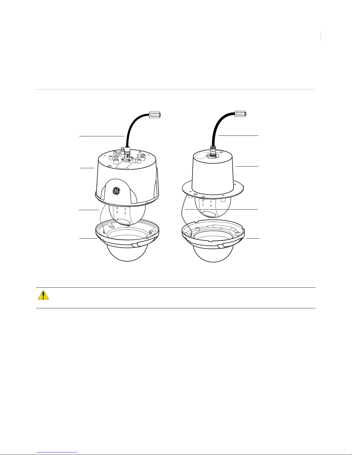
Figure 1 shows basic camera components. The camera mounting bracket is optional for surface installation.
Figure 1. Camera components
Pendant/surface-mount type Flush mount type
3
Power and
data cable
Dome
camera
body
Lanyard Lanyard
Power and
data cable
Dome
camera
body
Dome coverDome cover
Note: Pendant-mount type configurations have an IP66 environmental rating. Flush-mount and surface-mount configurations
do not.
CAUTION: Do not expose the power and data cable to moisture, this may cause leakage into the housing and damage
the camera. If you must, please make sure that the connections are sealed tightly.
Page 8
GE 16X PTZ Camera
4
Installation Manual
Junction board
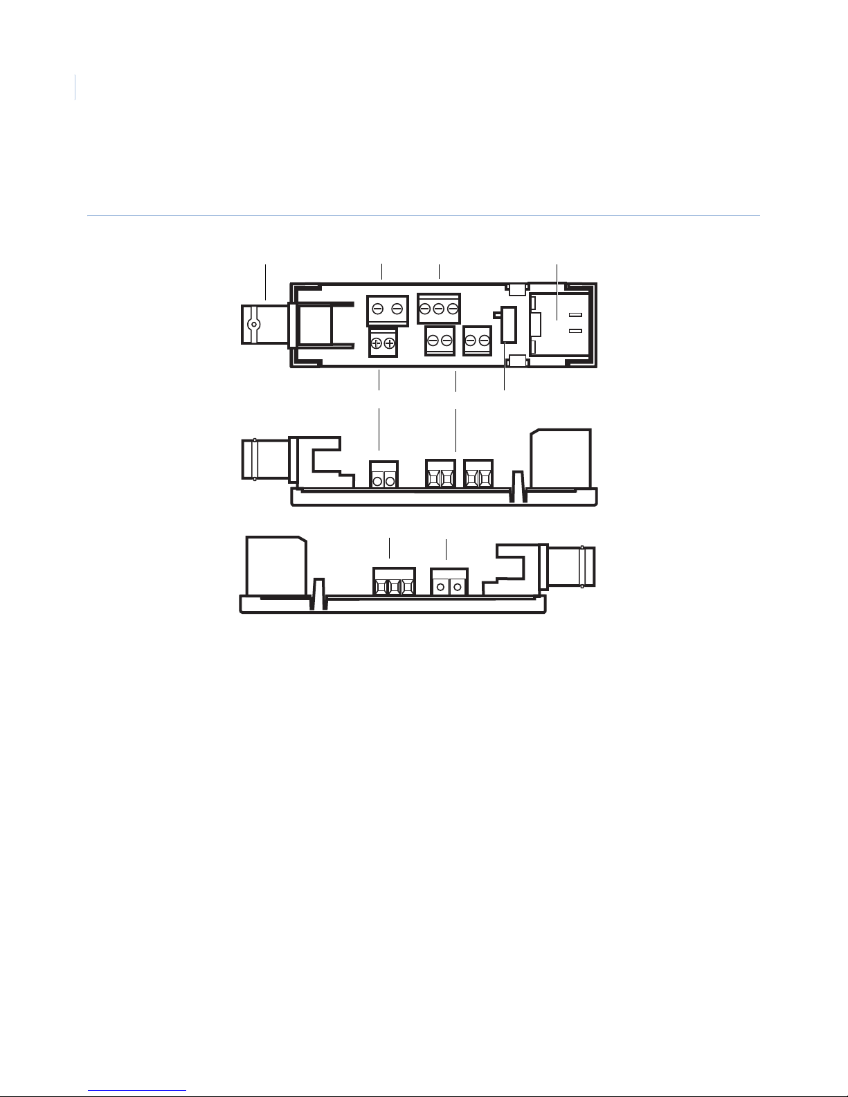
Figure 2 shows the junction board components.
Figure 2. Junction board
A
BC
D
UTP - UTP +
24VAC/DC B A B A
EG
A Video output jack with BNC connector
B Video output terminal with UTP connector
A1 C A2
OFF
ON
F
CB
C Alarm input (sensor input) terminal (A1: Alarm Input 1 / A2: Alarm Input 2)
D RJ45 connector
E 24 VAC/24 VDC terminal (UL listed class 2 power supply only)
F Data communication port
G Daisy chain termination on/off switch
Page 9
Connections
A qualified service person, complying with all applicable codes, should perform all required hardware
installation.
Note: Do not attempt to extend the power/data cable connection using RJ45 couplers and Cat5 cable. Only use the data cable
connection provided.
Note: Use 24 VAC / 24 VDC. (use a UL listed Class 2 power source only.)
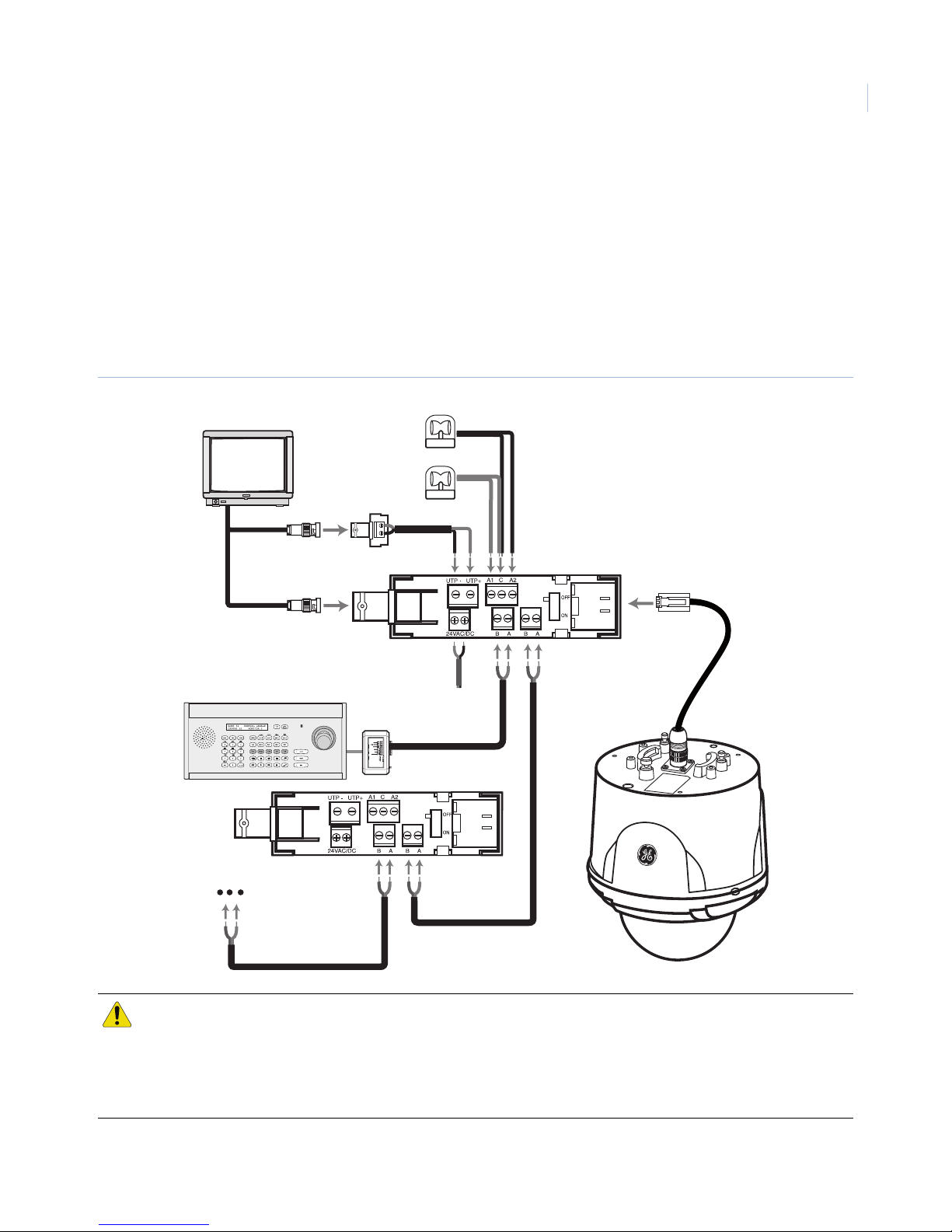
Figure 3 shows a typical camera installation.
Figure 3. Camera installation sample
5
or
CAUTION: Do not expose the power and data cable to moisture, which may cause damage to the camera. If you
cannot avoid installing the camera in a damp area, please make sure that the connections are sealed
tightly.
Pendant-mount configurations have an IP66 environmental rating. Flush-mount and surface-mount
configurations do not.
Page 10
GE 16X PTZ Camera
6
Installation Manual
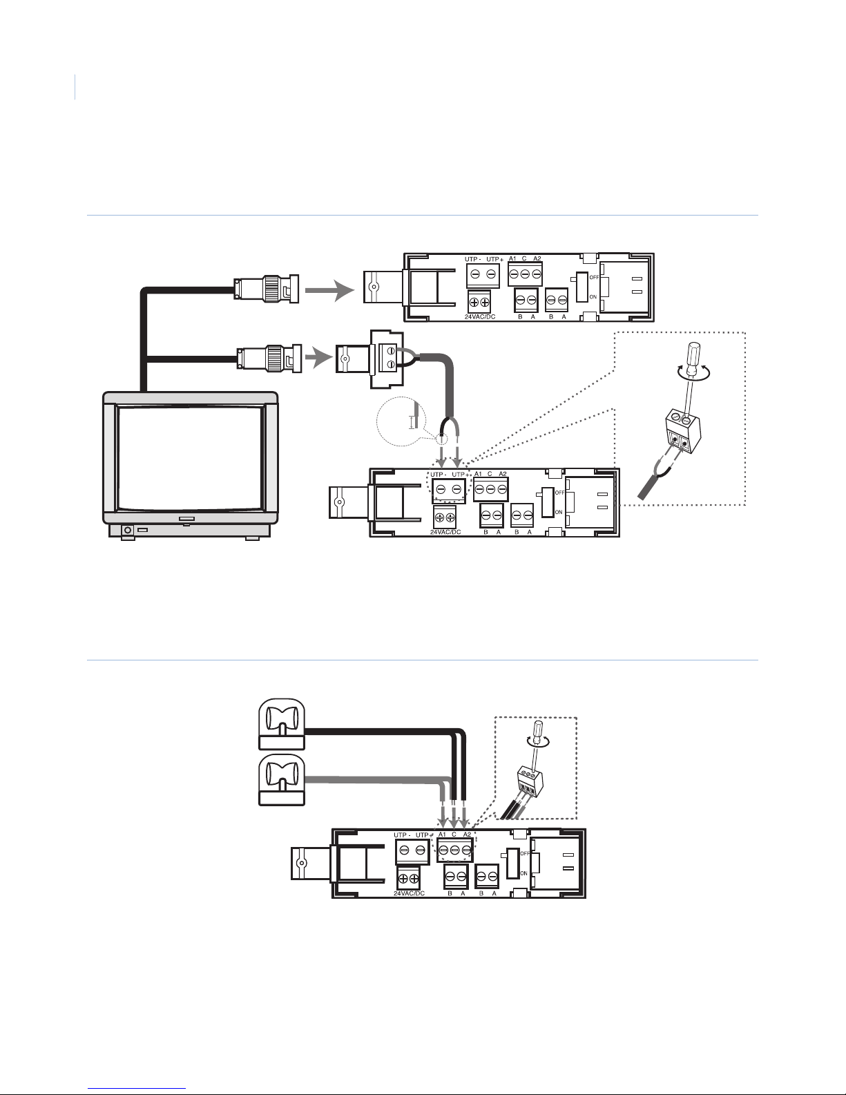
Monitor
Figure 4 shows the video signal connection between the camera and the monitor.
Figure 4. Monitor connection
or
5~7 mm
Alarm input
You can connect up to two alarm sensors to the camera (Figure 5). Connect each alarm sensor to C (Common).
You can adjust the signal state to NO (normally open) or NC (normally closed) through the setup menu.
Figure 5. Alarm input connections
Page 11
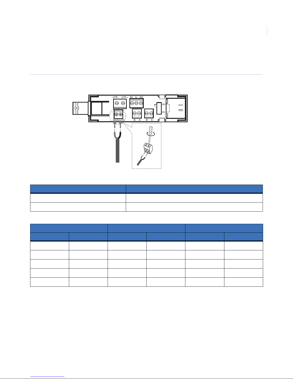
Power source
Connect only a 24 VAC/24 VDC UL listed Class 2 power source to the power input terminal (Figure 6).
Figure 6. Power source connection
7
Table 1. Power requirements
Model Maximum power
Flush mount (dome without fan) 16 VA
Surface mount (dome with fan x3) 25 VA
Table 2. Power cable size and length requirements
Wire gauge Flush mount (16 VA) Surface mount (25 VA)
AWG mm2 feet meter feet meter
14 1.62 744 226 465 141
16 1.29 469 143 293 89
18 1.02 295 89 185 56
20 0.81 186 56 117 35
22 0.64 116 35 73 22
Page 12
GE 16X PTZ Camera
8
Installation Manual
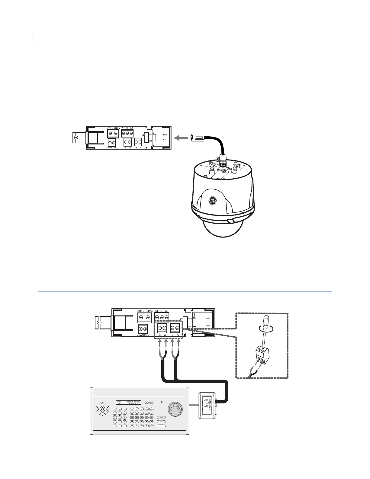
RJ45 cable
Connect the RJ45 cable from the camera to the RJ45 jack of the junction board (Figure 7).
Note: Do not attempt to extend the power/data cable connection using RJ-45 couplers. Only use the cable connection provided.
Figure 7. RJ45 cable connection
KTD-405/KTD-405A keypad
Connect the KTD-405/KTD-405A keypad to either data terminal on the junction board (Figure 8). These data
terminals are interchangeable.
Figure 8. KTD-405/KTD-405A connection
or
Page 13
Length and type of the RS-485/422 cable
RS-422 Digiplex and RS-485 Impac cable can be 22 gauge, twisted-pair, and have a maximum length of 3900
feet (1,200 meters).
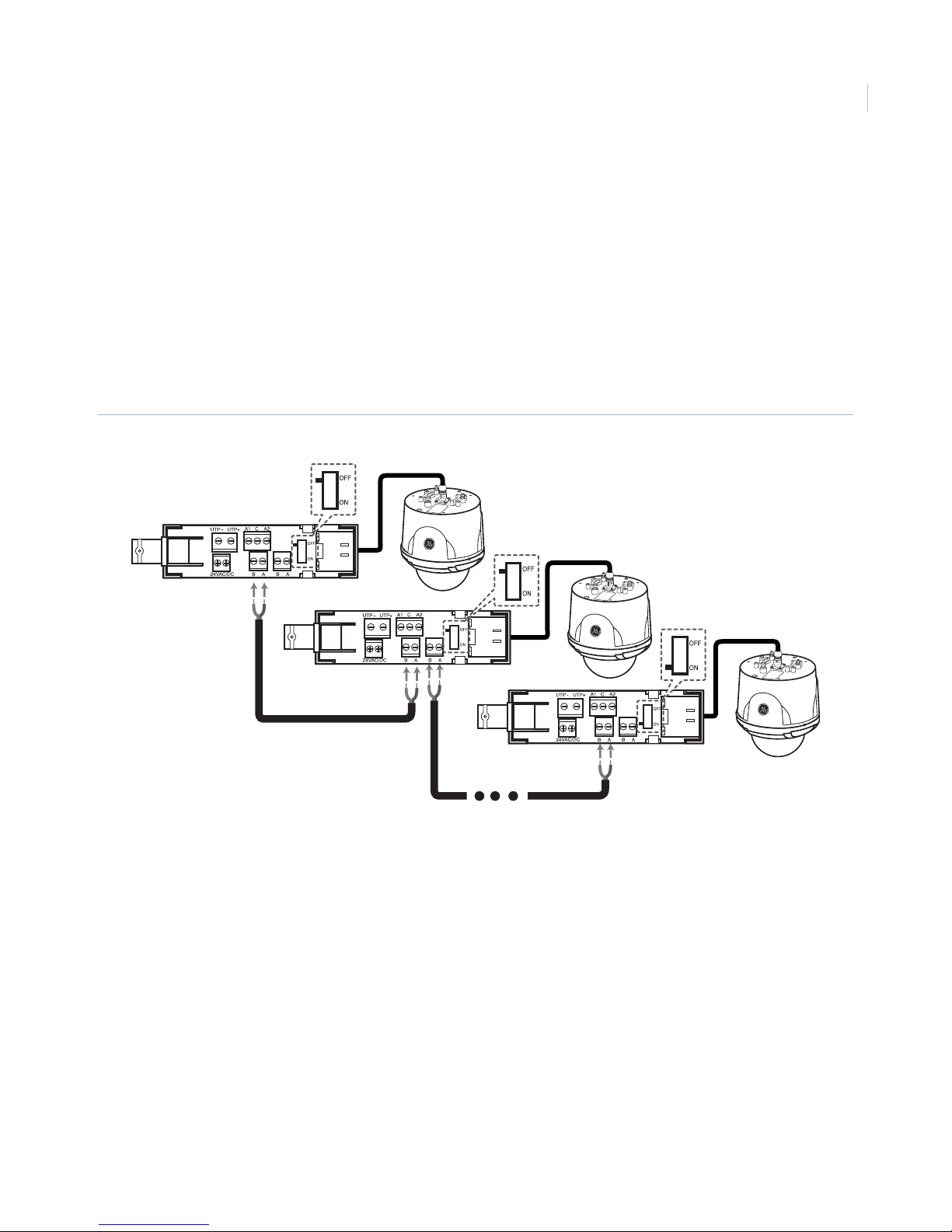
Connecting multiple GE 16X PTZ cameras in parallel
If you choose to daisy chain multiple cameras in the field, leave all camera termination switches off except for
the last camera in the chain which should be on (Figure 9). The cameras may not function properly if they are
not terminated correctly.
Note: If you are connecting only one GE 16X PTZ Camera to the junction board, you must set the termination switch to ON.
Figure 9. Multiple cameras connection
9
Page 14
GE 16X PTZ Camera
10
Installation Manual
Installation
Use the following installation guidelines:
• A qualified service person, complying with all applicable codes, should perform all required hardware
installation.
• Do not install the camera near the air outlet of an air conditioner.
• Be sure to hook the lanyard (fall prevention wire) onto a bracket.
• Seal cable parts tightly and do not expose them to rain or damp environments.
• Use a 24 VAC/24 VDC UL listed class 2 power supply only.
• When turned on, camera does a self-check, including panning, tilting, zooming, and focusing
operation.
Note: Pendant-mount type configurations are IP66 environmentally rated. Flush-mount and surface-mount configurations are
not.
WARNING: Be sure to switch the camera off before installation and connection.
Removing the protective tape
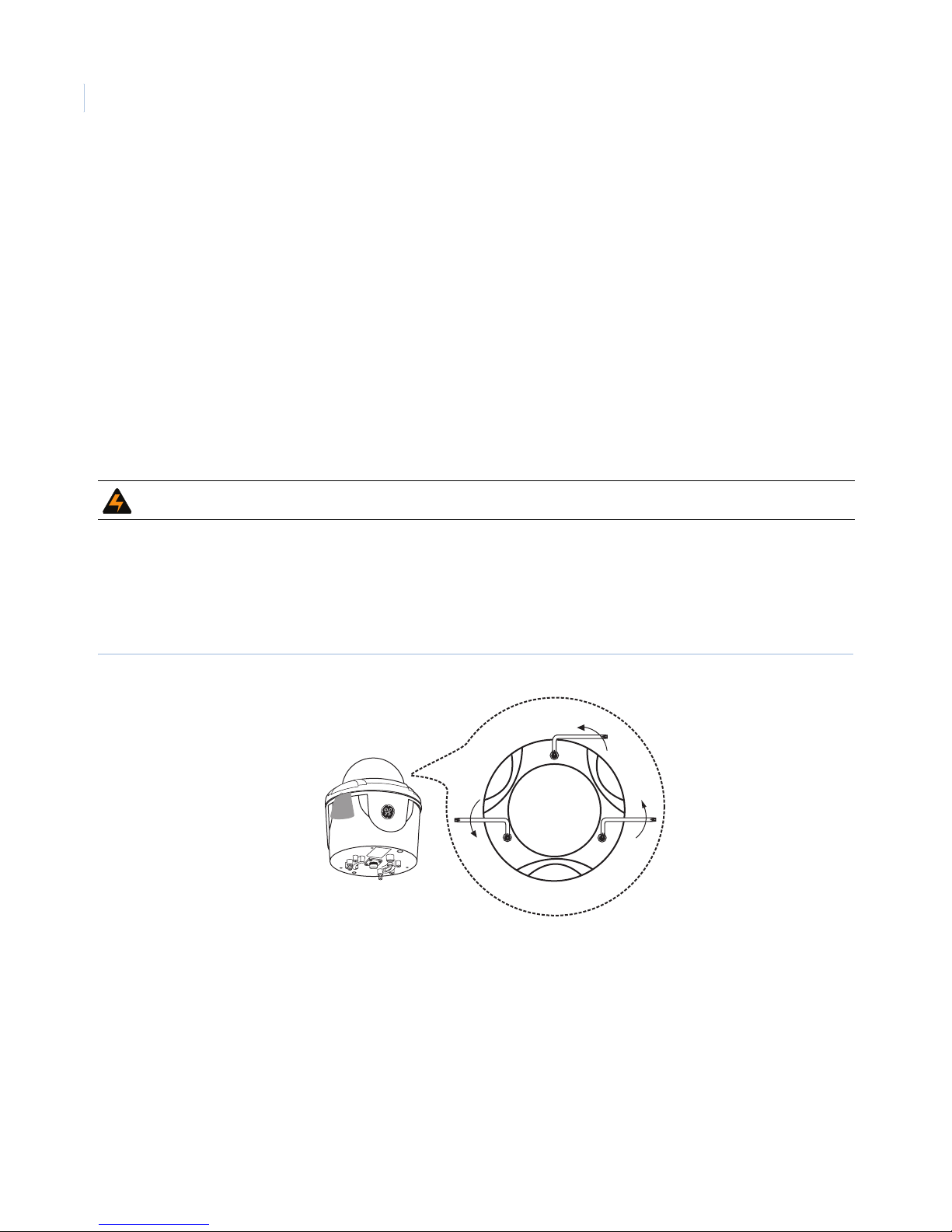
Before using the camera, you must remove the protective tape. To remove the tape, do the following:
1. Use the supplied Allen wrench to loosen the screws and remove the dome cover (Figure 10).
Figure 10. Loosen dome screws
Page 15
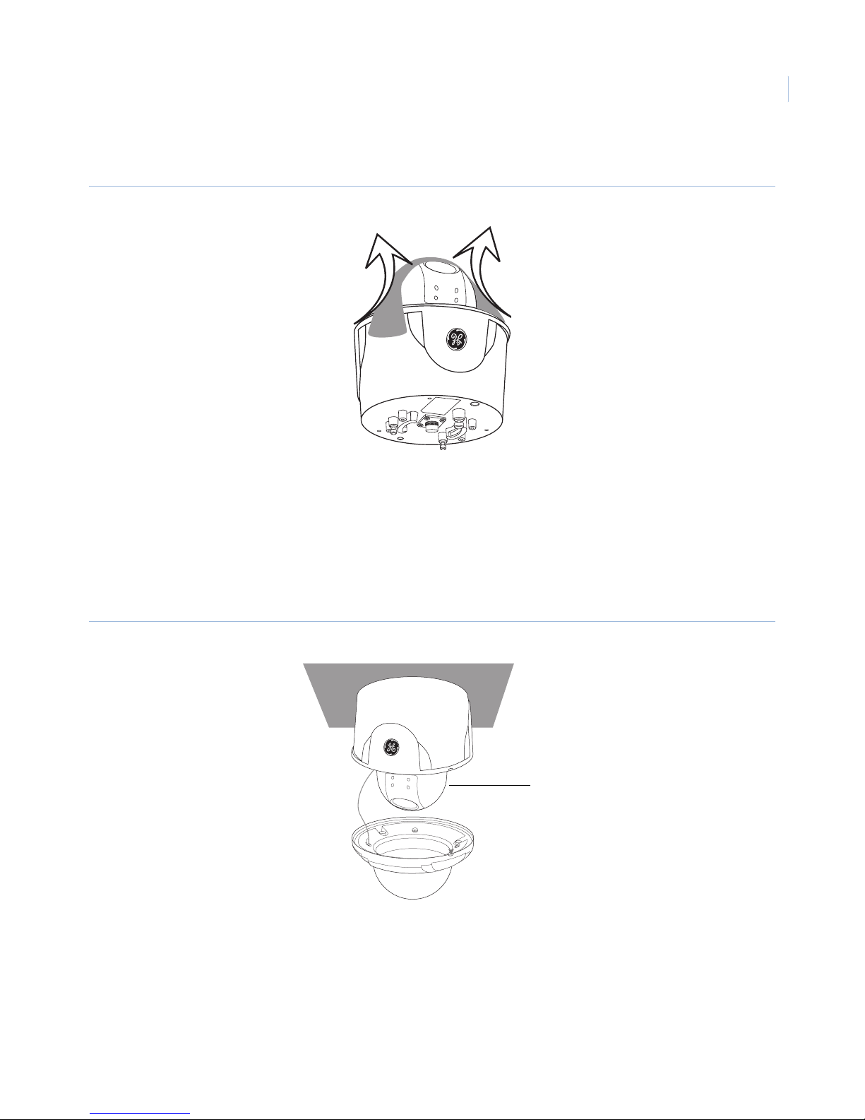
2. Carefully remove the protective tape (Figure 11).
Figure 11. Removing protective tape
11
Protocol and baud rate settings
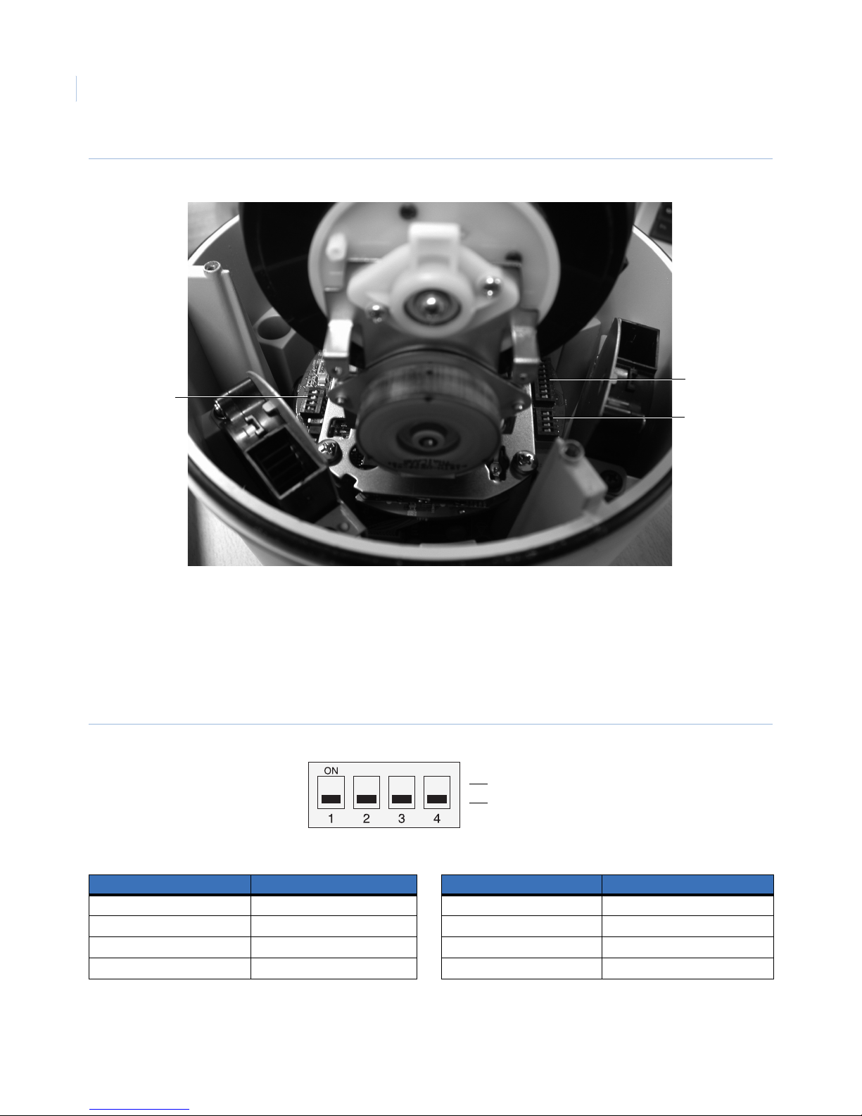
The camera has two 4-bit DIP switch blocks that determine the protocol and baud rate of the data
communication. Settings are loaded when the camera boots up. Be sure to turn the camera off, change the DIP
switch settings, and then power the camera back up to load the changes.
Note: If you have difficulty accessing the dip switches when the camera is installed, remove the camera shroud.
Figure 12. Camera shroud
Camera shroud
Page 16
GE 16X PTZ Camera
12
Installation Manual
Figure 13. DIP switch locations
Protocol
switch (SW101)
Camera ID
switch
Baud rate
switch (SW104
To set protocol (SW101) and baud rate parameters (SW104), do the following:
1. Turn the camera off.
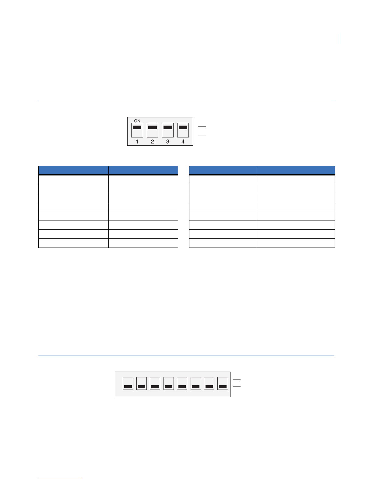
2. The SW104 DIP switch on the bottom of the camera (Figure 14 on page 12) sets the baud rate. Use
Tab le 3 to find the correct sequence of 1s (on) and 0s (off) for the baud rate that you want to use.
Note: SW104 is located next to the 8-bit camera ID DIP switch.
Figure 14. SW104
On (1)
Off (0)
Table 3. SW104 baud settings
Switch position Baud Switch position Baud
0, 0, 0, 0 9,600 bps 0, 1, 0, 0 19,200 bps
0, 0, 0, 1 1,200 bps 0, 1, 0, 1 38,400 bps
0, 0, 1, 0 2,400 bps 0, 1, 1, 0 57,600 bps
0, 0, 1, 1 4,800 bps (default) 0, 1, 1, 1 115,200 bps
Note: The baud rate for Digiplex 422 is 4800. The baud rate for IMPAC RS-485 is 9600. The baud rate for ASCII is 9600.
The Pelco P/D protocol requires no specific baud rate.
Page 17
3. The SW101 DIP switch on the bottom of the camera (Figure 15) sets the protocol. Use Tab le 4 to find
the correct sequence of 1s (on) and 0s (off) for the protocol that you want to use.
Note: SW101 is located on the opposite side of the board from the 8-bit camera ID DIP switch.
Figure 15. SW101
On (1)
Off (0)
Table 4. SW101 protocol settings
Switch position Protocol Switch position Protocol
1, 1, 1, 1 Digiplex 422 (default) 1, 1, 1, 0 Reserved 7
1, 0, 1, 1 ASCII 0, 1, 1, 0 Reserved 8
0, 1, 1, 1 IMPAC RS-485 1, 0, 1, 0 Reserved 9
0, 0, 1, 1 Pelco-D 0, 0, 1, 0 Reserved 10
1, 1, 0, 1 Pelco-P 1, 1, 0, 0 Reserved 11
0, 1, 0, 1 Reserved 4 0, 1, 0, 0 Reserved 12
1, 0, 0, 1 Reserved 5 1, 0, 0, 0 Reserved 13
0, 0, 0, 1 Reserved 6 0, 0, 0, 0 Reserved 14
13
4. Power up the camera to load the changes.
Camera ID setting
The camera’s ID is set to “1” as default. If you use two or more cameras simultaneously, change the ID of the
cameras.
To set the camera ID, do the following:
1. Locate the 8-bit camera ID DIP switch block on the bottom of the camera.
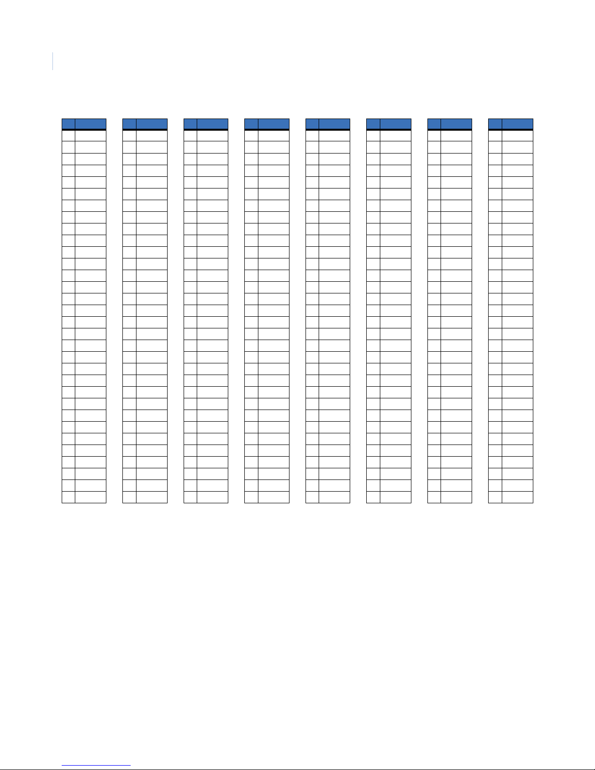
2. Using Figure 16 and Ta bl e 5 , determine how to set the DIP switches for the desired camera ID.
3. Place the switches that correspond to those values in the on position.
Figure 16. Camera ID DIP switch
ON
1 2 3 4 5 6 7 8
Equivalent value 1 2 4 8 16 32 64 128
On (1)
Off (0)
Page 18
GE 16X PTZ Camera
14
Installation Manual
Table 5. Camera ID DIP switch settings
# Switch
0 00000000
1 10000000
2 01000000
3 11000000
4 00100000
5 10100000
6 01100000
7 11100000
8 00010000
9 10010000
10 01010000
11 11010000
12 00110000
13 10110000
14 01110000
15 11110000
16 00001000
17 10001000
18 01001000
19 11001000
20 00101000
21 10101000
22 01101000
23 11101000
24 00011000
25 10011000
26 01011000
27 11011000
28 00111000
29 10111000
30 01111000
31 11111000
# Switch
32 00000100
33 10000100
34 01000100
35 11000100
36 00100100
37 10100100
38 01100100
39 11100100
40 00010100
41 10010100
42 01010100
43 11010100
44 00110100
45 10110100
46 01110100
47 11110100
48 00001100
49 10001100
50 01001100
51 11001100
52 00101100
53 10101100
54 01101100
55 11101100
56 00011100
57 10011100
58 01011100
59 11011100
60 00111100
61 10111100
62 01111100
63 11111100
# Switch
64 00000010
65 10000010
66 01000010
67 11000010
68 00100010
69 10100010
70 01100010
71 11100010
72 00010010
73 10010010
74 01010010
75 11010010
76 00110010
77 10110010
78 01110010
79 11110010
80 00001010
81 10001010
82 01001010
83 11001010
84 00101010
85 10101010
86 01101010
87 11101010
88 00011010
89 10011010
90 01011010
91 11011010
92 00111010
93 10111010
94 01111010
95 11111010
# Switch
96 00000110
97 10000110
98 01000110
99 11000110
100 00100110
101 10100110
102 01100110
103 11100110
104 00010110
105 10010110
106 01010110
107 11010110
108 00110110
109 10110110
110 01110110
111 11110110
112 00001110
113 10001110
114 01001110
115 11001110
116 00101110
117 10101110
118 01101110
119 11101110
120 00011110
121 10011110
122 01011110
123 11011110
124 00111110
125 10111110
126 01111110
127 11111110
# Switch
128 00000001
129 10000001
130 01000001
131 11000001
132 00100001
133 10100001
134 01100001
135 11100001
136 00010001
137 10010001
138 01010001
139 11010001
140 00110001
141 10110001
142 01110001
143 11110001
144 00001001
145 10001001
146 01001001
147 11001001
148 00101001
149 10101001
150 01101001
151 11101001
152 00011001
153 10011001
154 01011001
155 11011001
156 00111001
157 10111001
158 01111001
159 11111001
# Switch
160 00000101
161 10000101
162 01000101
163 11000101
164 00100101
165 10100101
166 01100101
167 11100101
168 00010101
169 10010101
170 01010101
171 11010101
172 00110101
173 10110101
174 01110101
175 11110101
176 00001101
177 10001101
178 01001101
179 11001101
180 00101101
181 10101101
182 01101101
183 11101101
184 00011101
185 10011101
186 01011101
187 11011101
188 00111101
189 10111101
190 01111101
191 11111101
# Switch
192 00000011
193 10000011
194 01000011
195 11000011
196 00100011
197 10100011
198 01100011
199 11100011
200 00010011
201 10010011
202 01010011
203 11010011
204 00110011
205 10110011
206 01110011
207 11110011
208 00001011
209 10001011
210 01001011
211 11001011
212 00101011
213 10101011
214 01101011
215 11101011
216 00011011
217 10011011
218 01011011
219 11011011
220 00111011
221 10111011
222 01111011
223 11111011
# Switch
224 00000111
225 10000111
226 01000111
227 11000111
228 00100111
229 10100111
230 01100111
231 11100111
232 00010111
233 10010111
234 01010111
235 11010111
236 00110111
237 10110111
238 01110111
239 11110111
240 00001111
241 10001111
242 01001111
243 11001111
244 00101111
245 10011111
246 01101111
247 11101111
248 00011111
249 10011111
250 01011111
251 11011111
252 00111111
253 10111111
254 01111111
255 11111111
Page 19
Mounting the camera
You can mount the camera on a ceiling or wall.
Flush-mount
A flush-mount type camera is required for this installation.
Note: The flush-mounted camera housing is not IP66 rated.
To flush mount the camera, do the following:
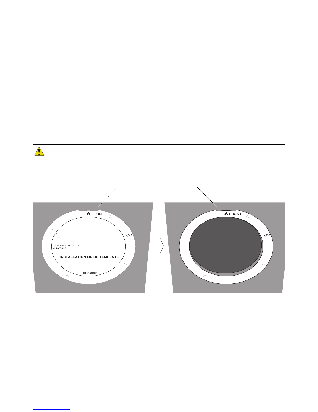
1. Use the installation guide template to check the mounting location. Face the front of the label toward
the area of interest. Using the template as a guide, make a hole through the ceiling (Figure 17).
CAUTION: The building superstructure must be able to support 80 lb. (36 kg).
Figure 17. Installation guide template
15
WHEN ANY MOUNT
CUT OFF CEILING LINE
Notch must face toward area of interest
Page 20
GE 16X PTZ Camera
16
Installation Manual
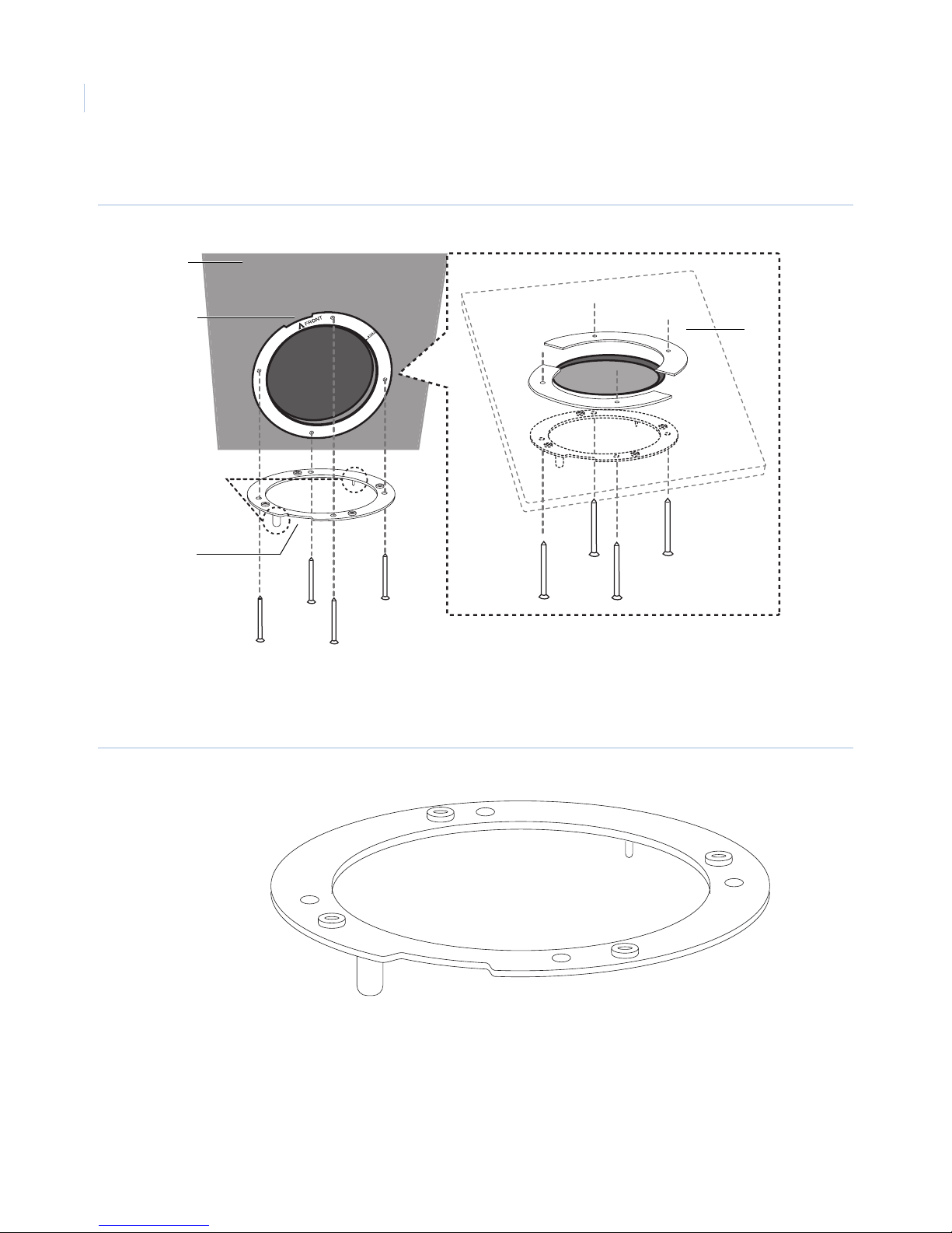
2. Fasten the camera assembly bracket to the ceiling. Face the location pins downward (Figure 18).
Figure 18. Camera assembly bracket
Ceiling
Notch must face
towards area of
interest
Location
pins
Notch must face
towards area of
interest
Inside ceiling
Note: For this installation, you must use the bracket depicted in Figure 19. The GE 16X PTZ camera models have different
brackets that are designed to work with specific models
Figure 19. Flush-mount bracket
Page 21
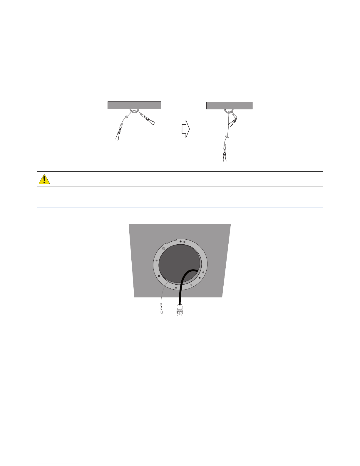
3. Fasten the dome safety cable to the building superstructure (Figure 20). The building superstructure
can vary depending on your installation environment.
Figure 20. Dome safety cable
CAUTION: The building structure must be able to support 80 lb. (36 kg).
4. Pass the connection cable and the safety cable through the hole so that they hang down (Figure 21).
17
Figure 21. Connection cable
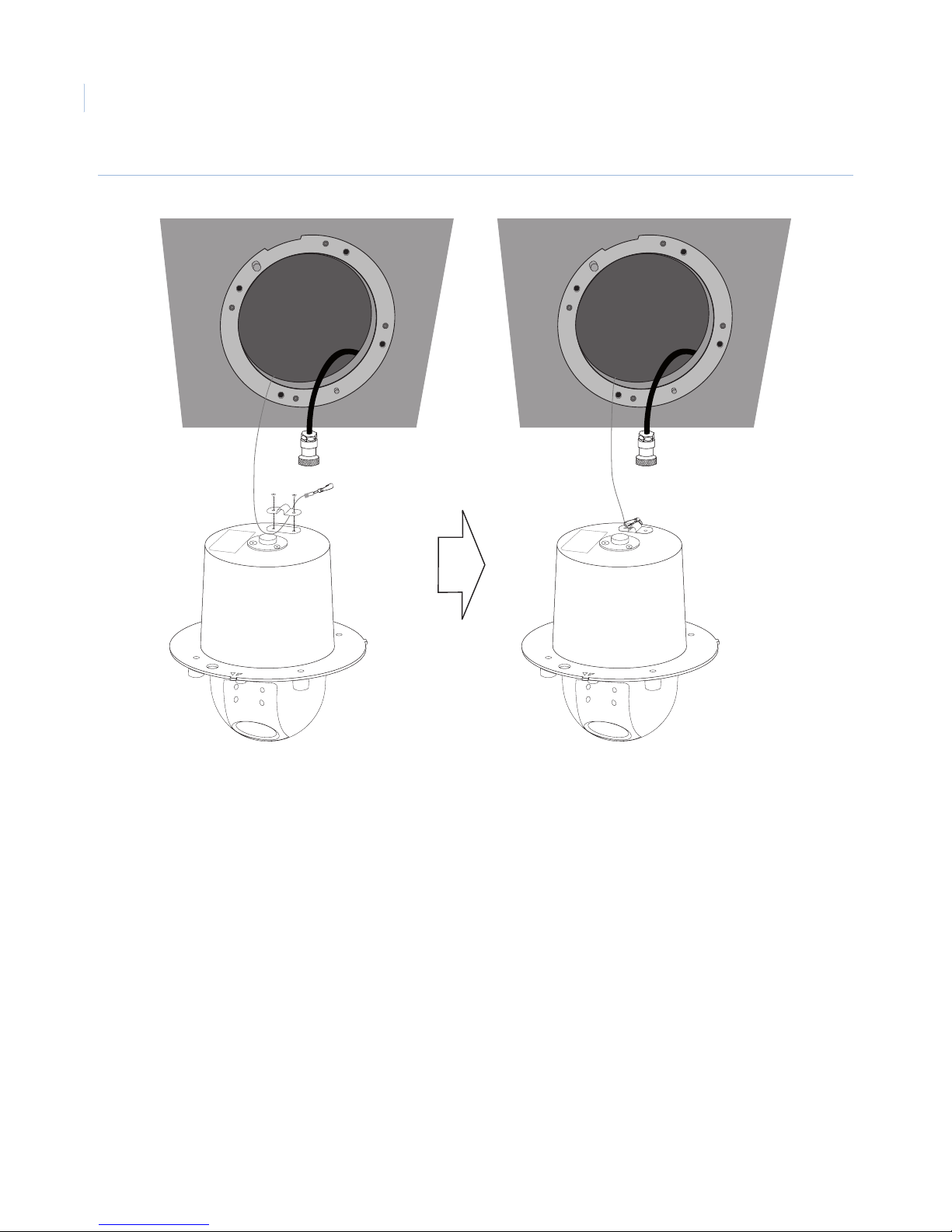
5. Using the two smallest screws in the mounting hardware kit, connect the safety cable to the camera
body with the safety bracket (Figure 22).
Page 22
GE 16X PTZ Camera
18
Installation Manual
Figure 22. Safety cable to camera
Page 23
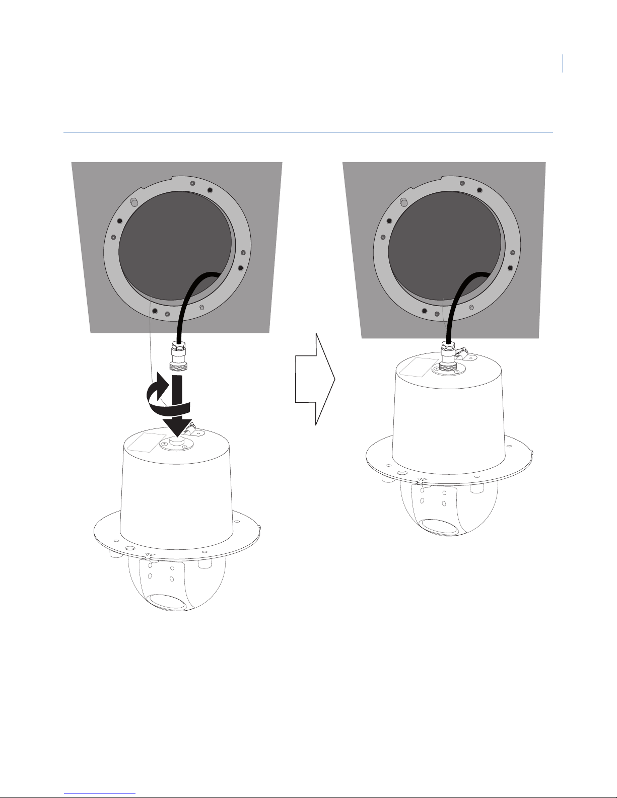
6. Connect the cable to the terminal on the camera body (Figure 23).
Figure 23. Cable connection
19
Page 24
GE 16X PTZ Camera
20
Installation Manual
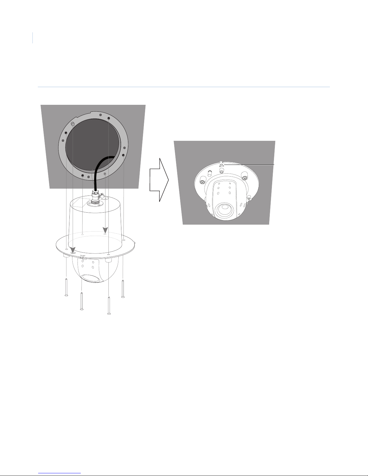
7. Fasten the camera body to the camera assembly bracket (Figure 24 on page 20). For proper
orientation, use the location pins to align the camera.
Figure 24. Camera body to bracket installation
When installed properly,
the arrow points toward
the area of interest. If
not go back to step two
and reorient camera
assembly bracket.
Page 25
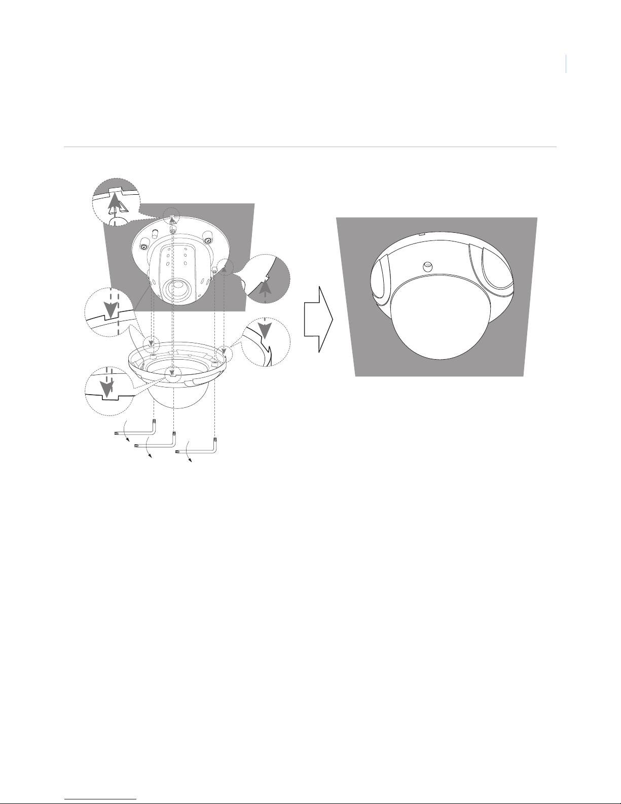
8. Assemble the camera cover and camera body. Fasten the screws using the supplied Allen wrench
(Figure 25).
Figure 25. Camera cover assembly
21
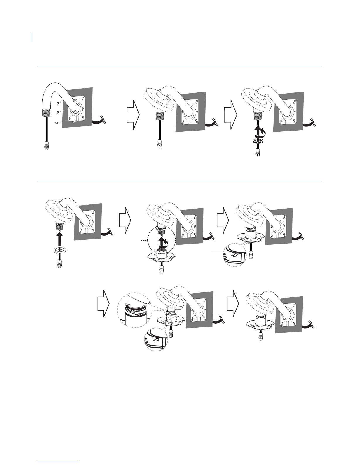
Optional wall-mount
Note: Requires a pendant/surface type camera along with wall-mount kit GEC-DV-WM.
To wall-mount the camera, do the following:
1. Drill holes in the wall where you want to install the wall-mount.
2. Install the wall-mount (Figure 26 on page 22).
Page 26
GE 16X PTZ Camera
22
Installation Manual
Figure 26. Pipe installation
3. Install the camera installation bracket (Figure 27).
Figure 27. Camera installation bracket
A
“A ”
Arrow
towards
area of
interest
Pipe threads should be clean and rust-free. Use a sealer such as PTFE tape and silicone sealer on the
threads
A.
Page 27
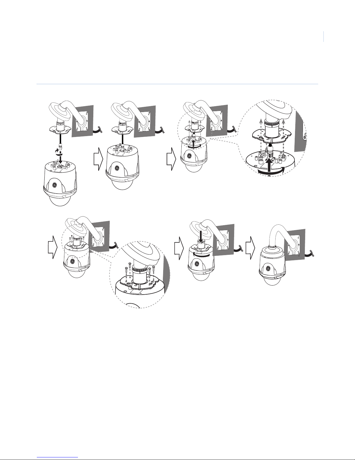
4. Connect the RJ45 cable to the RJ45 camera jack and attach the camera to the installation bracket
(Figure 28).
Figure 28. RJ45 cable and camera installation
23
Note: If properly installed, the GE logo should face toward the area of interest, or in this case, away from the wall. If it does not,
go back to step 3 and readjust camera installation bracket.
Page 28
GE 16X PTZ Camera
24
Installation Manual
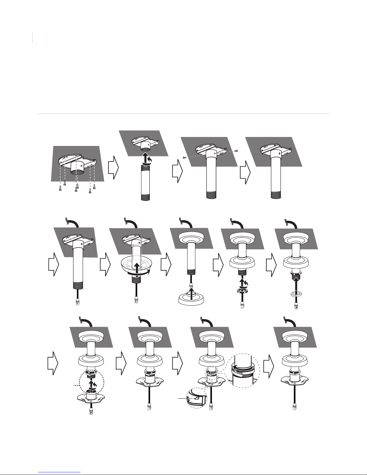
Optional pendant-mount
The pendant-mount kit GEC-DV-PM is for installation of a pendant/surface type camera.
To install the camera with a pendant-mount, do the following:
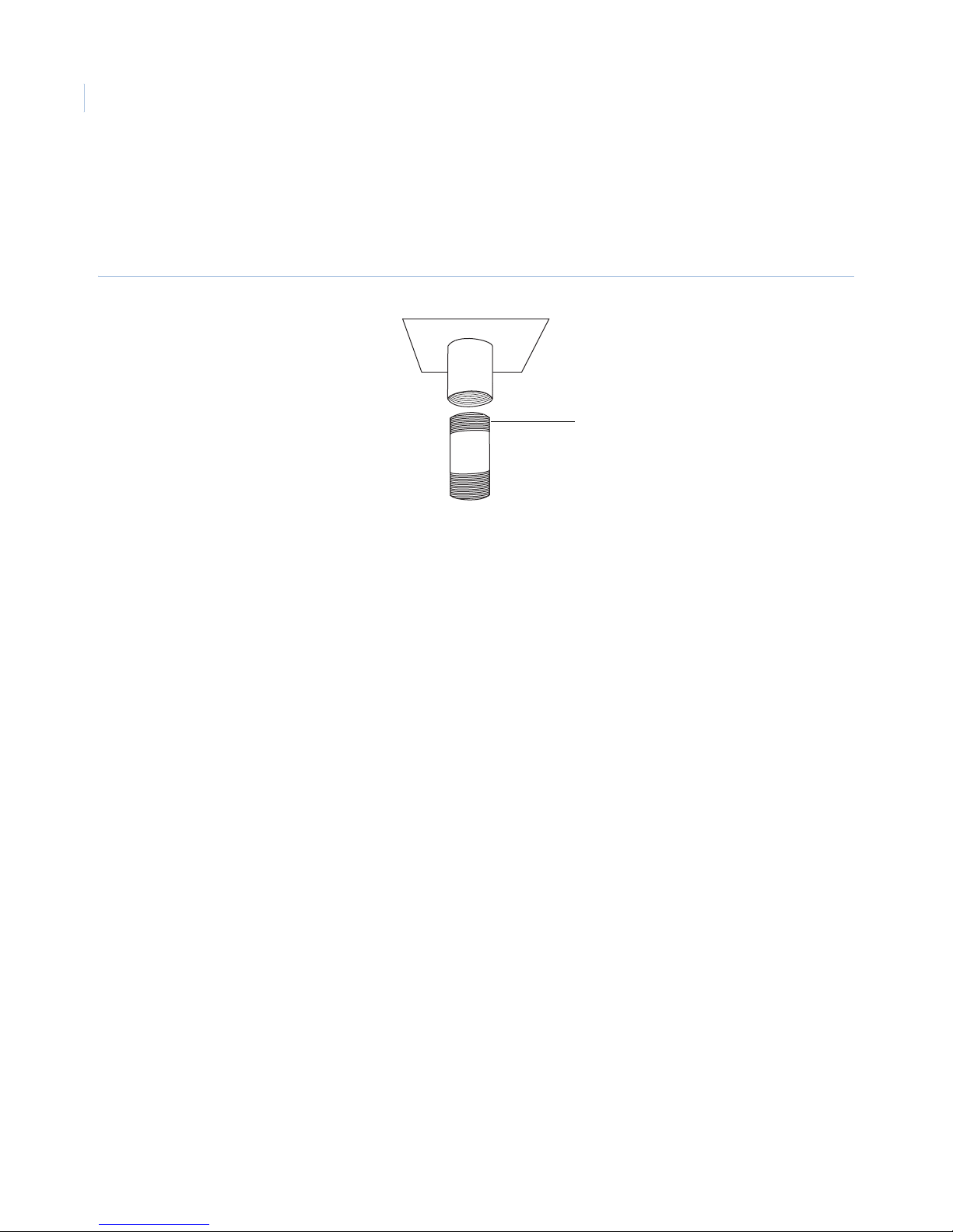
1. Install the pipe and camera installation bracket (Figure 29).
Figure 29. Pipe and camera installation bracket
A
Pipe threads should be clean and rust-free. Use a sealer such as PTFE tape or silicone sealer on the threads
of both ends of the pipe
A.
Arrow
towards
area of
interest
Page 29
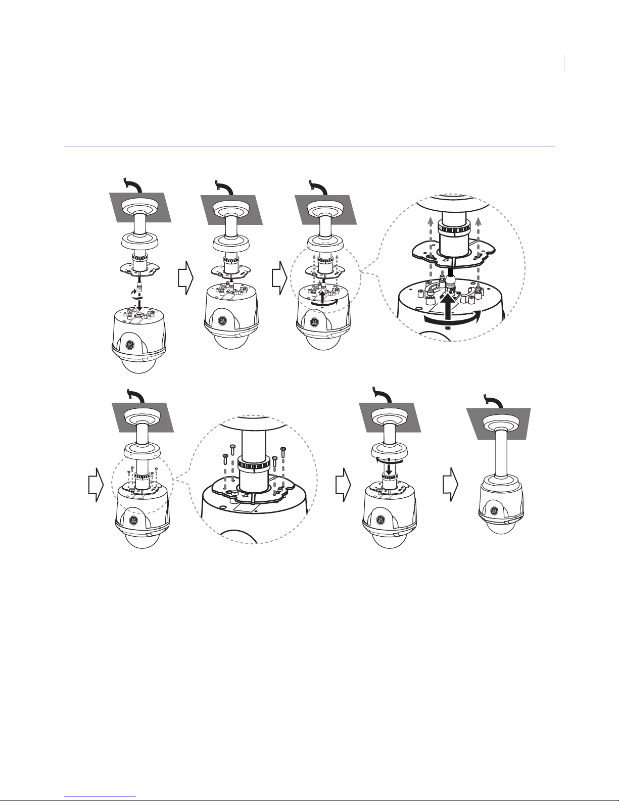
2. Connect the RJ45 cable to the RJ45 jack of the camera and attach the camera to the installation bracket
(Figure 30).
Figure 30. Connect the camera
25
Note: When properly installed, the GE logo should face toward the area of interest. If it does not , readjust the lower camera
installation bracket.
Page 30
GE 16X PTZ Camera
26
Installation Manual
Pipe mount
GE Security offers two pipe-mount adapter kits designed for use with two different types of threaded pipe. The
GEC-DV-PMA model is for 1-1/4 11.5 NPT threaded pipe, and the GEC-DV-BSP model is for 1-1/4 BSP
threaded pipe. The pipe-mount adapter kits are for installation of a pendant/surface type camera.
Figure 31. Pipe mount adapter
NPT 1 1/4 inch or EN 10226 R 1 1/4
Add thread ceiling tape
to both ends of pipe
1. Add thread-sealing tape to both ends of your pipe. Pipe threads should be clean and rust free.
depending on your adapter kit. This
end of the pipe is slightly tapered.
Page 31
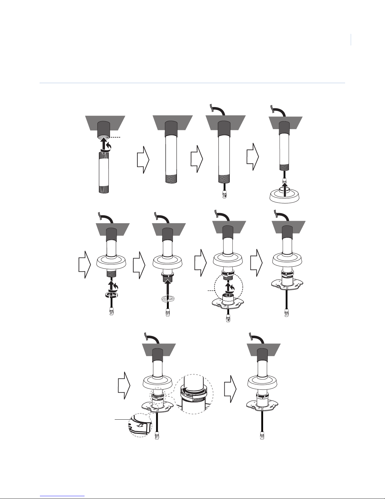
2. Install the NPT/BSP pipe and camera installation brackets (Figure 32).
Figure 32. NPT/BSP pipe installation
A
27
A
Arrow
towards
area of
interest
Pipe threads should be clean and rust free. Use a sealer such as PTFE tape or silicone sealer on the threads
A.
Page 32
GE 16X PTZ Camera
28
Installation Manual
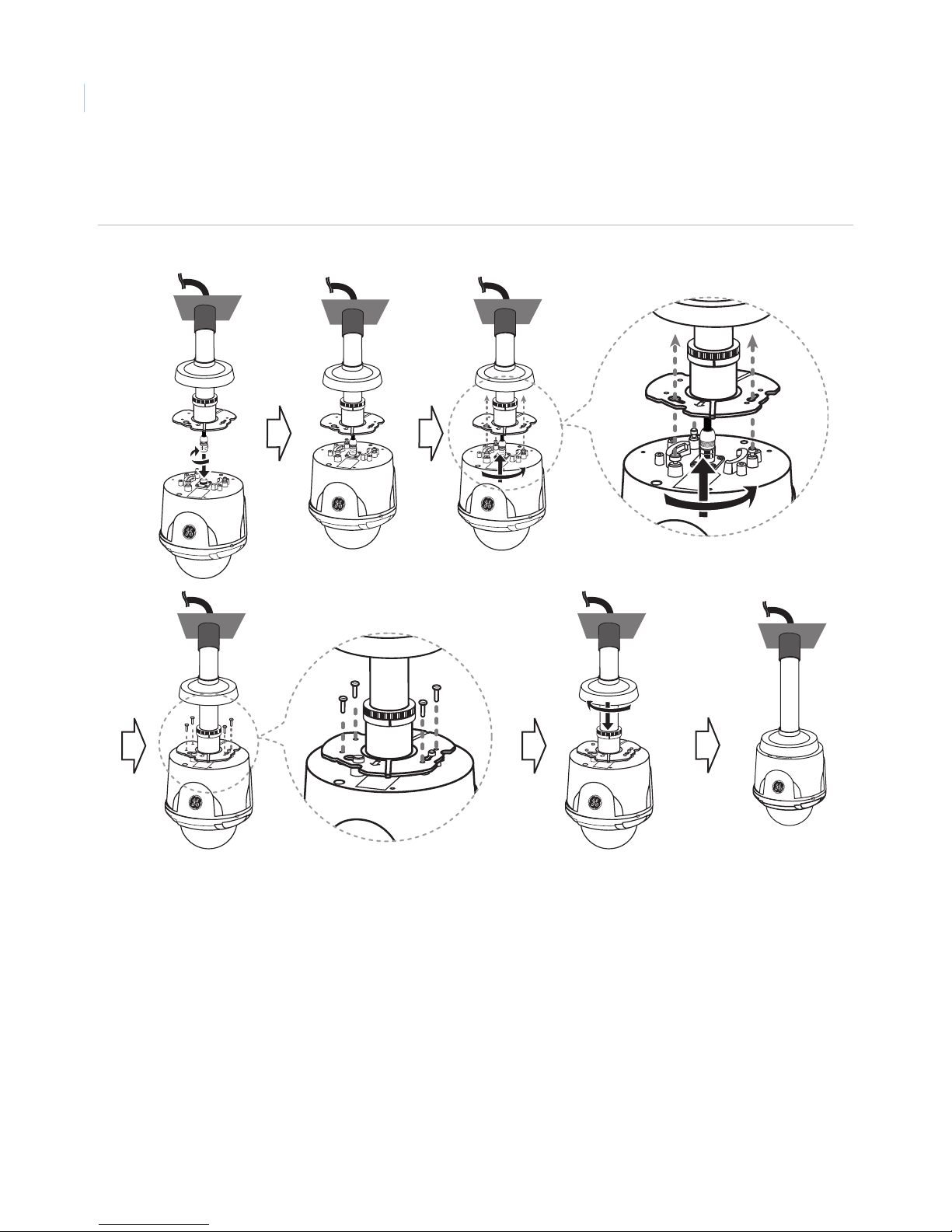
Figure 33. RJ45 cabling
3. Connect the RJ45 cable to the RJ45 jack of the camera and install the camera to the installation bracket
(Figure 33).
Note: If properly installed, the GE logo should face area of interest. If it does not, readjust the lower camera installation bracket.
Page 33
Surface-mount
Note: The camera is no longer IP66 rated after surface mounting the camera.
To surface-mount the camera, do the following:
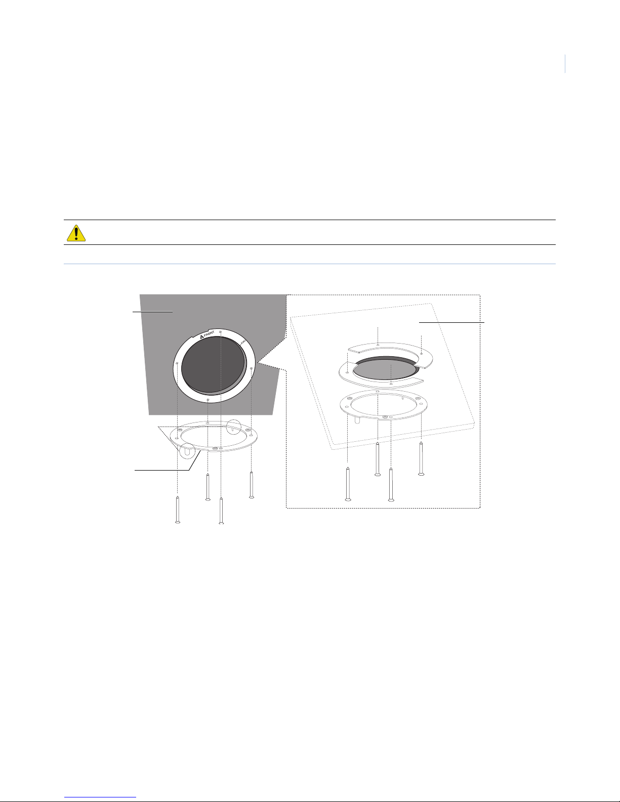
1. Use the installation guide template to check the mounting location. Point the arrow on the label marked
“Front” towards the area of interest. Using the template as a guide, make a hole through the ceiling
(Figure 17).
CAUTION: The building superstructure must be able to support 80 lb. (36 kg).
Figure 34. Camera assembly bracket
Ceiling
Inside ceiling
29
Location
pins
Notch should face
area of interest
Note: For this installation, you must use the bracket depicted in Figure 35 on page 30. The GE 16X PTZ camera models have
different brackets that are designed to work with specific models.
Page 34
GE 16X PTZ Camera
30
Installation Manual
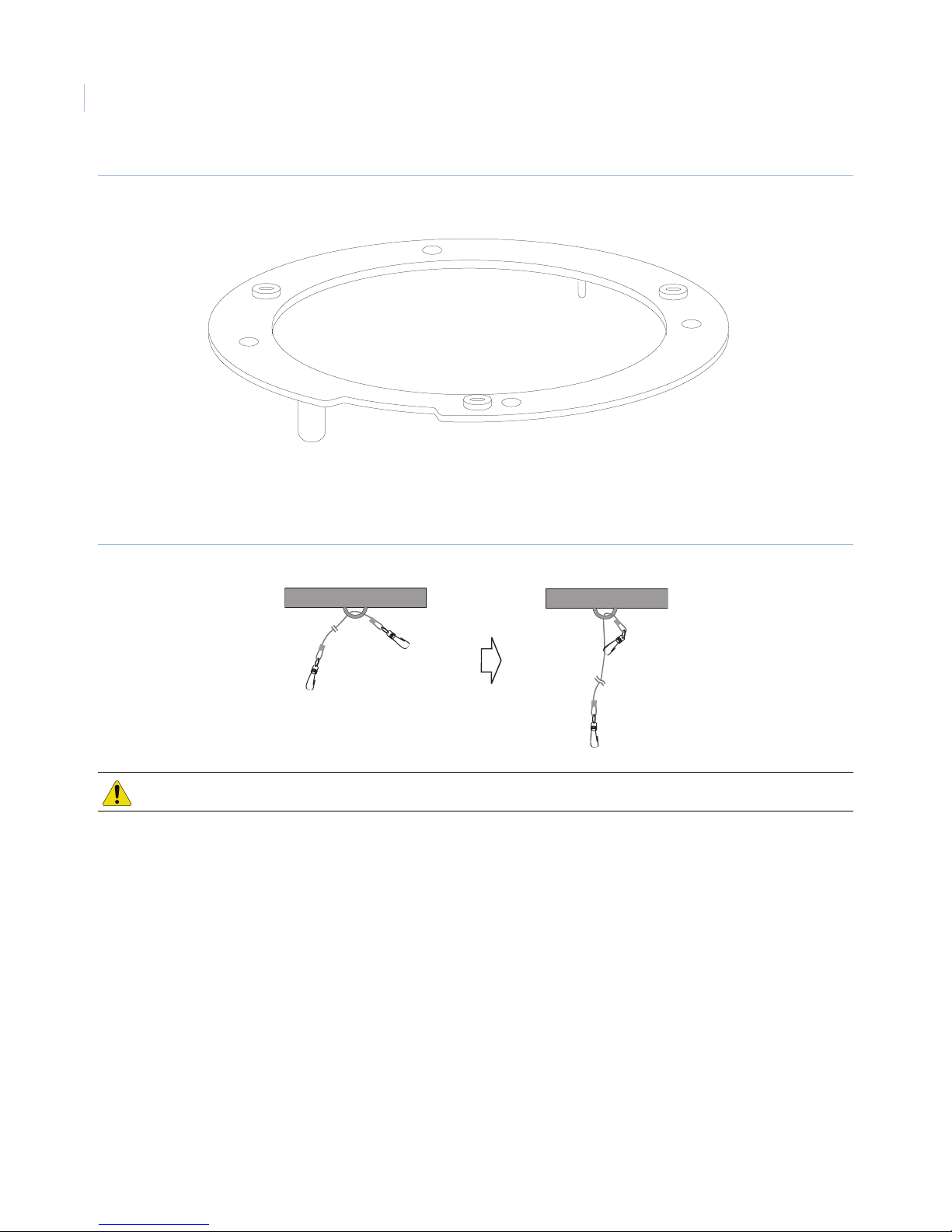
Figure 35. Surface-mount bracket
2. Fasten the dome safety cable to the building superstructure (Figure 20). The building superstructure
can vary depending on your installation environment.
Figure 36. Dome safety cable
CAUTION: The building structure must be able to support 80 lb. (36 kg).
Page 35
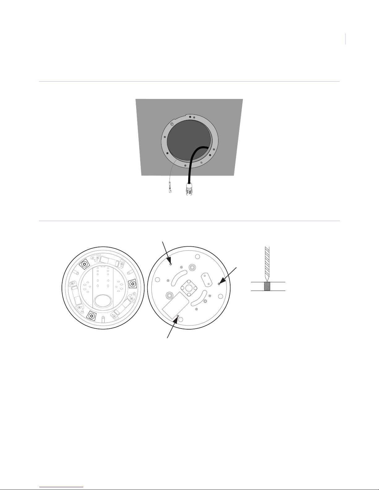
3. Pass the connection cable and the safety cable through the inner side of the ceiling (Figure 21).
Figure 37. Connection cable
4. Drill three holes in the camera housing as shown in Figure 38.
31
Figure 38. Drilling holes in the bottom of the camera housing
Note: The camera is no longer IP66 rated after drilling the holes.
5/32 in. (4.0 mm) diameter
Page 36
GE 16X PTZ Camera
32
Installation Manual
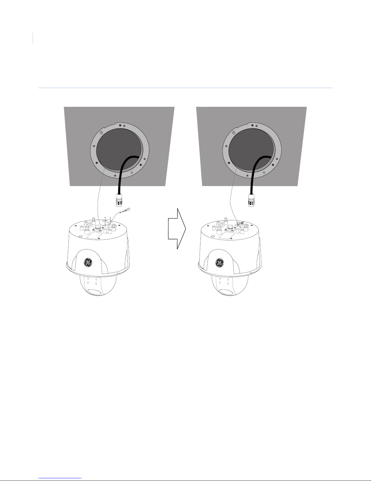
5. Using the two smallest screws in the mounting hardware kit, connect the safety cable to the camera
body with the safety bracket (Figure 22).
Figure 39. Safety cable to camera
Page 37
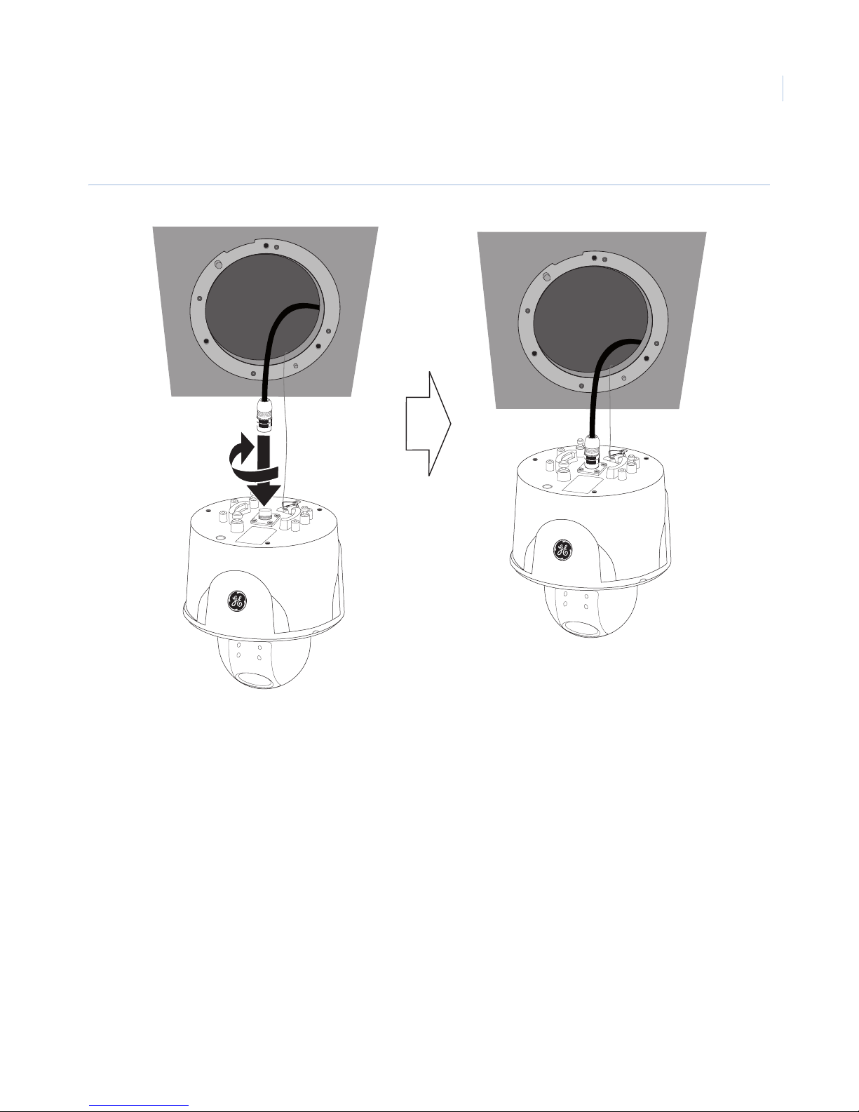
6. Connect the cable to the terminal on the camera body (Figure 23).
Figure 40. Cable connection
33
Page 38
GE 16X PTZ Camera
34
Installation Manual
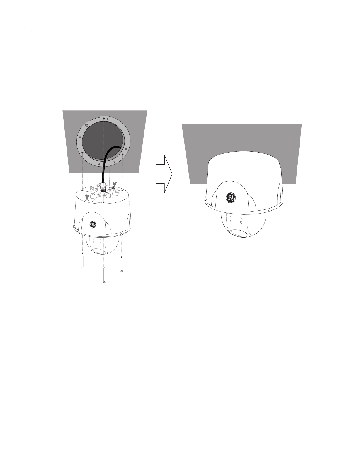
7. Fasten the camera body to the camera assembly bracket (Figure 24). For proper orientation, use the
location pins to align the camera.
Figure 41. Camera body to bracket installation
Page 39
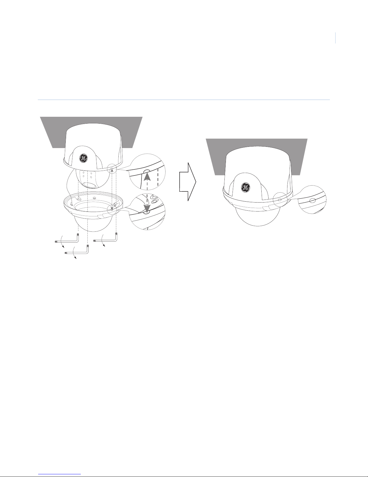
8. Assemble the camera cover and camera body. Fasten the screws using the hexagonal wrench
(Figure 25).
Note: The GE logo should face the area of interest. If it does not, go back to step 1 to reorient the assembly bracket.
Figure 42. Camera cover assembly
35
Page 40

GE 16X PTZ Camera
36
Installation Manual
Contacting us
For help installing, operating, maintaining, and troubleshooting this product, refer to this document and any
other documentation provided. If you still have questions, contact us during business hours (Monday through
Friday, excluding holidays, between 5 a.m. and 5 p.m. Pacific Time).
Table 6. Technical support
North America Latin America
T: 888 GE Security (888.437.3287) Toll-free in the US,
Puerto Rico, and Canada.
503.885.5700 outside the toll-free area.
F: 888.329.0332 (Tualatin tech support)
561.998.6232 (Boca Raton tech support)
Australia, New Zealand China, India, Singapore, Taiwan, Southeast Asia
Note: Be ready at the equipment before calling.
T: 305.593.4301
F: 305.593.4300
E:
Europe, Middle East, and Africa
W: At www.gesecurity.eu, select Customer Support.
Online resources
Here are some useful links on our website www.gesecurity.com:
Online library. From the Customer Support menu, select the Resource Library link. After you register
and log on, you may search for the documentation you need.
Training. To view any available online training for GE Security products, select the Training link. (Online
training is not available for all products.)
Warranty and terms information. From the Customer Support menu, select Return and Warranty
Policy Statement or Terms and Conditions Policy Statement.
Customer service and technical support. From the Customer Support menu, select Customer Service or
Technical & Application. Select the appropriate product category for the contact information or use the
menu to select a location outside the US.
1
1. Many GE documents are provided in English only as PDFs. To read these documents, you will need Adobe Reader, which you
can download free from Adobe’s website at www.adobe.com.
 Loading...