

GE PTU463SAMR, PTV16SAMR, PTQ470SAMR, PTV19SAMR, PTU527SAMR Technician Service Manual
...
g GE Appliances Service Training
_____________________________
TECHNICIAN
SERVICE MANUAL
Refrigerator
MODELS:
PTV15SAMR PTU427SAMR PTQ440SAMR
PTV16SAMR PTU463SAMR PTQ470SAMR
PTV19SAMR PTU527SAMR PTQ530SAMR
PTV20SAMR PTU565SAMR PTQ570SAMR
PTG440SAMR
PTG470SAMR
PTG530SAMR
PTG570SAMR
PUB NO. : SPWR1027E
JULY 2001
Page 1

IMPORTANT SAFETY NOTICE
r
r
r
r
The information in this service guide is intended fo
use by individuals possessing adequate backgrounds
of electrical, electronic and mechanical experience.
Any attempt to repair a major appliance may result in
personal injury and property damage. The
manufacturer or seller cannot be responsible for the
interpretation of this information, nor can it assume
any liability in connection with its use.
WARNING
To avoid personal injury, disconnect power before
servicing this product. If electrical power is required
for diagnosis or test purposes, disconnect the powe
immediately after performing the necessary checks.
RECONNECT ALL GROUNDING
DEVICES
If grounding wires, screws, straps, clips, nuts, o
washers used to complete a path to ground are
removed for service, they must be returned to thei
original position and properly fastened.
Page 2

THE MANUAL COVERS THE
FOLLOWING MODELS
MODEL # COUNTRY
PTU427SAMR
PTU463SAMR
PTU527SAMR
PTU565SAMR
N/A BANGLADESH
N/A CHINA
N/A HONG KONG
N/A INDIA
PTG440SAMR
PTG470SAMR
PTG530SAMR
AUSTRALIA /
NEW ZEALAND
INDONESIA /
THAILAND /
VIETNAM
PTG570SAMR
N/A JAPAN
N/A KOREA
N/A MALAYSIA
Page 3

THE MANUAL COVERS THE
FOLLOWING MODELS
MODEL # COUNTRY
N/A PAKISTAN
PTV15SAMR
PTV16SAMR
PTV19SAMR
PTV20SAMR
PTQ440SAMR
PTQ470SAMR
PTQ530SAMR
PTQ570SAMR
N/A TAIHITI
N/A TAIWAN
PHILIPPINES
SINGAPORE
Page 4
I. SPECIFICATION
PTV16SAMR
PTU463SAMR
PTQ470SAMR
PTG470SAMR
PTU427SAMR
PTQ440SAMR
PTG440SAMR
Models
PTV20SAMR
PTU565SAMR
PTQ570SAMR
PTG570SAMR
PTV19SAMR
PTU527SAMR
PTQ530SAMR
PTG530SAMR
Type 2-door 2-door 2-door 2-door
Height 1803 1703 1774 1674
Width 754 754 674 674Net dimension (mm)
Depth 560 733 706 706
Rated storage volume (liter) F:139 / R:391 F:139 / R:346
System Heater system
Start AutomaticDefrosting
Common
Finish Automatic
Temperature control Automatic (Adjustable)
No frost freezer
ÖÖÖÖ
Interior lamp 1 1 1 1
Caster 2 2
Evaporating pan 1 1 1 1
PTV15SAMR
Ice storage box 1 1 1 1
Transparent plastic shelf 2 2 1 2
Twisted ice tray Twin ice cube maker
Freezer
Transparent door racks 2 2 2 2
Deodorizing device
Multi air flow
Chilled room
ÖÖÖÖ
ÖÖÖÖ
ÖÖÖÖ
Transparent shelf with steel frame 3 2 3 2
Vegetable crisper with moisture
control
Traditional vegetable crisper 1 1 1 1
Refrigerator
ÖÖ
Transparent door racks 4 3 4 3
Large bottle/beer storage rack 1 1 1 1
Egg storage bucket 2 2 2 2
Page 5
I. SPECIFICATION
PTV20SAMR
Models
Silver
Color
Black
PTU565SAMR
PTQ570SAMR
PTG570SAMR
ÖÖÖÖ
ÖÖÖÖ
PTV19SAMR
PTU527SAMR
PTQ530SAMR
PTG530SAMR
PTV16SAMR
PTU463SAMR
PTQ470SAMR
PTG470SAMR
Rated voltage (V) / Frequency (Hz) 240 VAC / 50 Hz ; 220 VAC / 50 Hz ; 220 VAC / 60 Hz
Rated input (W) 180 180 170 170
Refrigerant (R-134a) charging
quantity
weight
Nte weight (Kg) 83 78 74 63
175g 165g 155g
Poor material SS SS SS SS
Source, Comp. & Net
Recessed handle
ÖÖÖÖ
PTV15SAMR
PTU427SAMR
PTQ440SAMR
PTG440SAMR
155g
Page 6

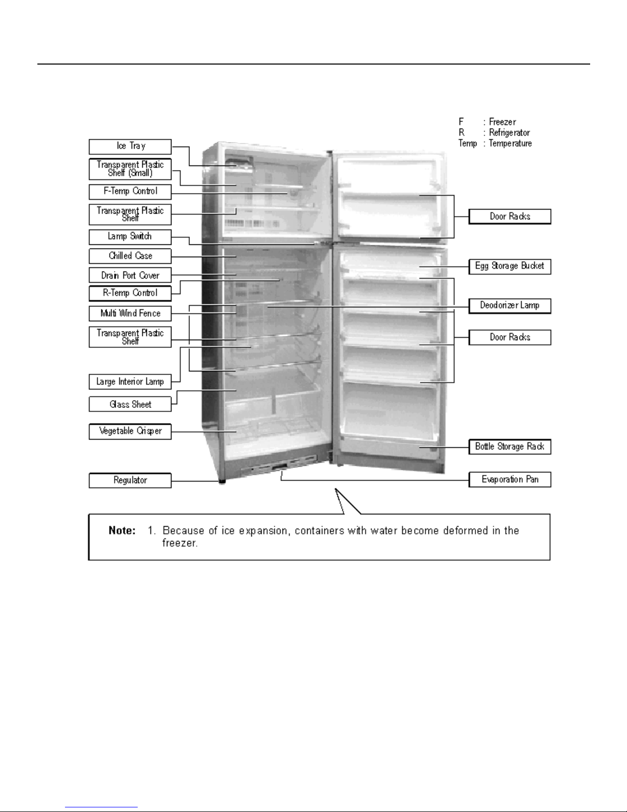
II. PARTS IDENTIFICATION
PTV15SAMR / PTU427SAMR / PTQ440SAMR / PTG440SAMR
PTV16SAMR / PTU463SAMR / PTQ470SAMR / PTG470SAMR
PTV15SAMR / PTU427SAMR / PTQ440SAMR / PTG440SAMR has 2 Transparent Plastic Shelves & 3 Door Racks
PTV16SAMR / PTU463SAMR / PTQ470SAMR / PTG470SAMR has 3 Transparent Plastic Shelves & 4 Door Racks
Features:
Ice tray : Can make and store 1kg of ice cubes.
Chilled Case : The fish and meats which will be cooked within 2 days can store
Evaporation Pan : Water discharged from the refrigerator is evaporated here.
Door Racks (F) : Short-term storage of frozen food.
Egg Storage Basket : Can store 16 eggs.
Door Racks (R) : Short-term storage of refrigerated food.
Bottle Storage Rack : Can store 5 bottles of beer or soda.
Regulator : For regulation of the refrigerator.
here, no thawing is required.
Page 7
II. PARTS IDENTIFICATION
PTV19SAMR / PTU527SAMR / PTQ530SAMR / PTG530SAMR
PTV20SAMR / PTU565SAMR / PTQ570SAMR / PTG570SAMR
PTV15SAMR / PTU427SAMR / PTQ440SAMR / PTG440SAMR has 2 Transparent Plastic Shelves & 3 Door Racks
PTV16SAMR / PTU463SAMR / PTQ470SAMR / PTG470SAMR has 3 Transparent Plastic Shelves & 4 Door Racks
Features:
Ice tray : Can make and store 1kg of ice cubes.
Chilled Case : The fish and meats which will be cooked within 2 days can store
here, no thawing is required.
Evaporation Pan : Water discharged from the refrigerator is evaporated here.
Door Racks (F) : Short-term storage of frozen food.
Egg Storage Basket : Can store 20 eggs.
Door Racks (R) : Short-term storage of refrigerated food.
Bottle Storage Rack : Can store 5 bottles of beer or soda.
Regulator : For regulation of the refrigerator.
Page 8
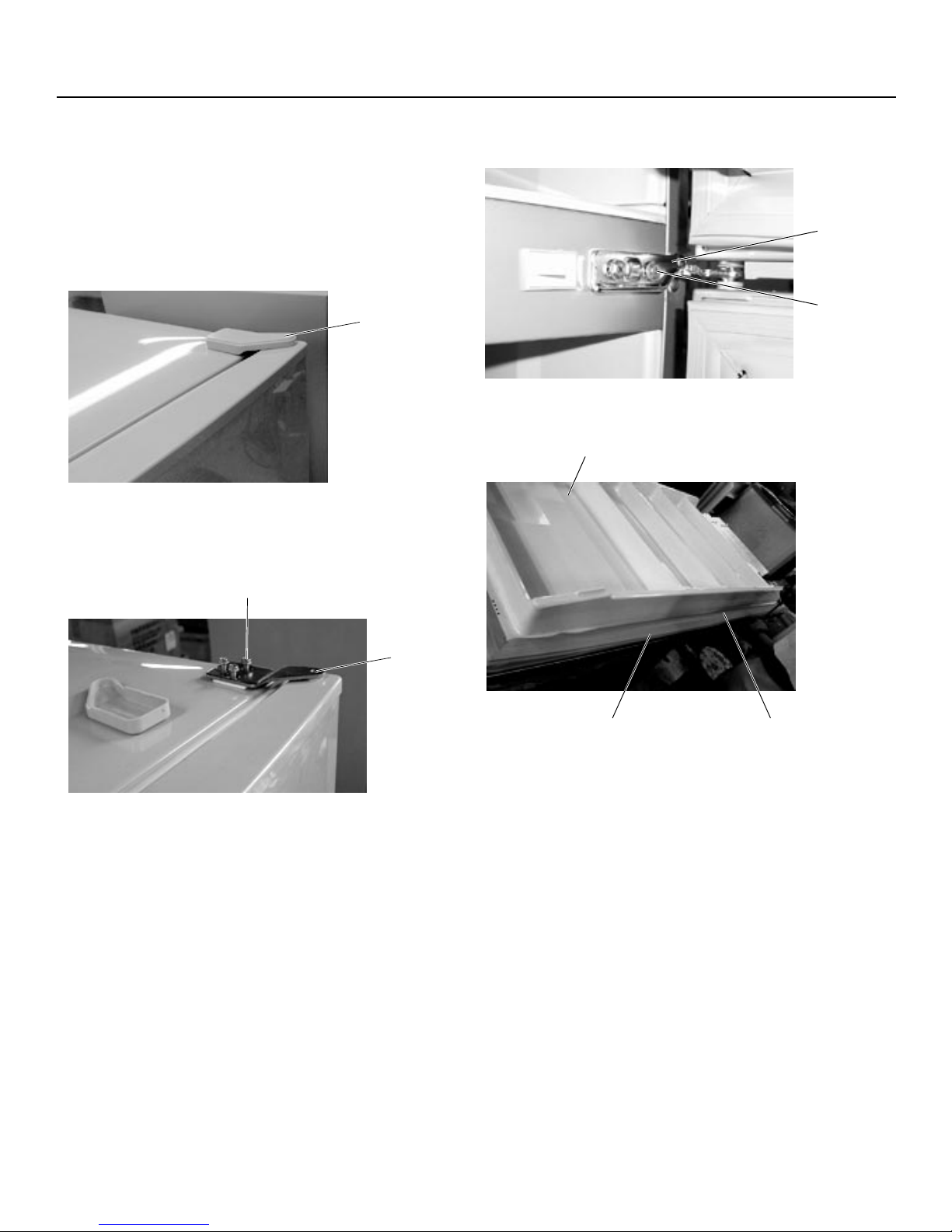
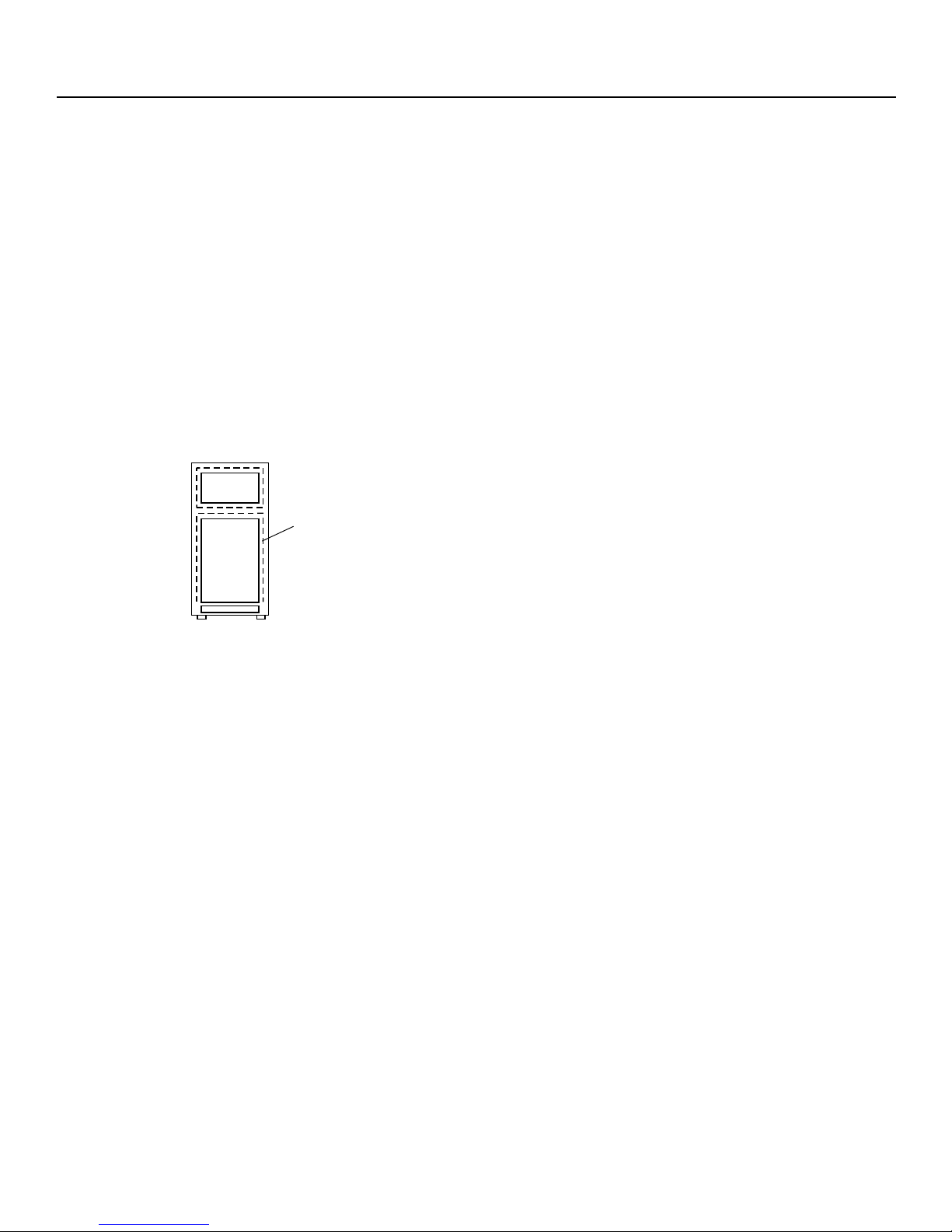
3.1 REPLACEMENT OF DOOR
III. SERVICE GUIDE
3.1.1 Remove the top hinge cover. Twist
and remove carefully not to hurt the
cover and cabinet with driver.
top hinge cover
3.1.2 Remove the screw and top hinge
assy.
screw
top hinge
center hinge
fix screw
3.1.5 Remove the door liner.
door liner
3.1.3 Remove the F door assy slightly and
remove it.
3.1.4 Remove the center hingr and remove
the R door assy.
remove screw with driverdoor packing
Page 9

III. SERVICE GUIDE
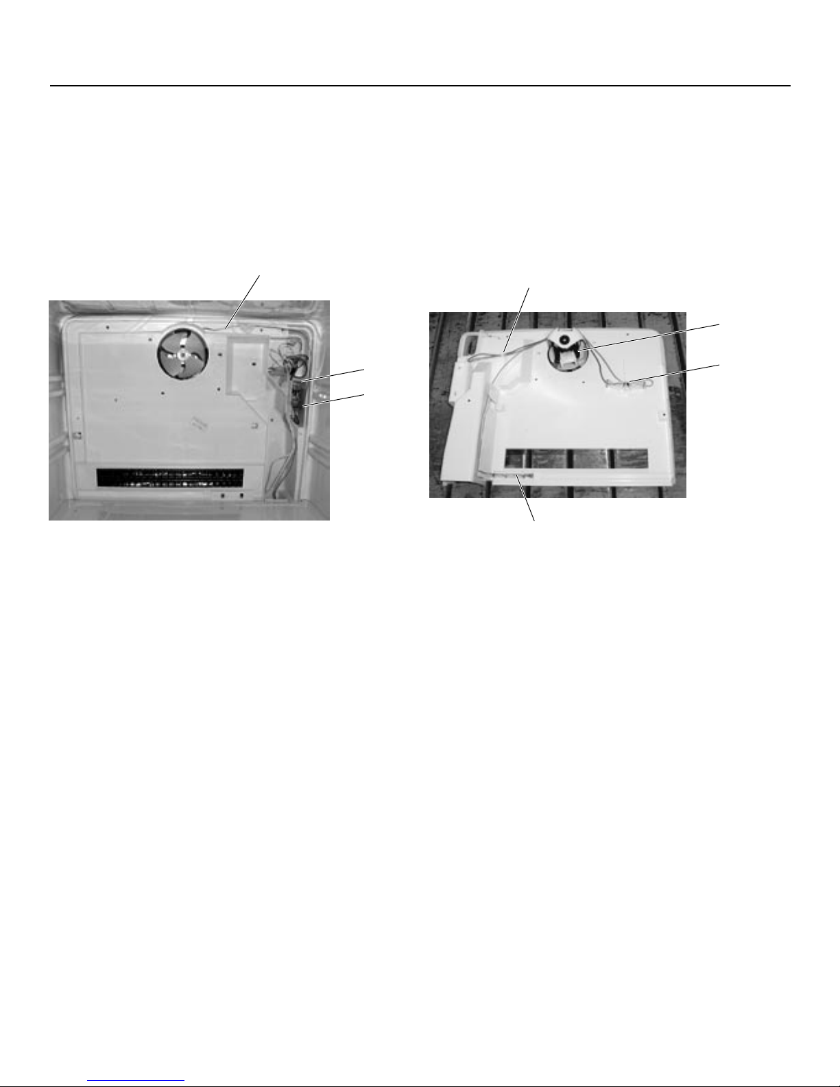
3.2 REPLACEMENT OF HEATER
3.2.1 Draw out the ice storage box.
3.2.2 Pull the case holder of ice silder.
3.2.3 Remove screw and F knob.
3.2.4 Remove F louver and pull the connector.
3.2.7 Remove the heater cover.
3.2.8 Remove the screws (2 pcs).
screw
EV assy
screw
F louver
F knob
screw
EV cover assy
3.2.5 Remove EV cover screw and remove the
EV cover.
fanscrew
connector
F-THM
3.2.6 Remove the EV screw and up the EV
assy.
foil
3.2.9 Rend the al. foil and remove heater
support.
3.2.10 Remove heater.
heaterheater support
screw
heater cover
Page 10
III. SERVICE GUIDE
3.3 REPLACEMENT OF F-THERMO
3.3.1 Remove F-THM screw.
3.3.2 Remove F-THM and replacement.
THM tube
screw
F-THM
3.4 REPLACEMENT OF DEFROST
THERMO
3.4.1 Remove D-band.
3.4.2 Remove D-THM assy and replace it.
D band
fan motor
defrost thermo
fuse
Page 11
III. SERVICE GUIDE
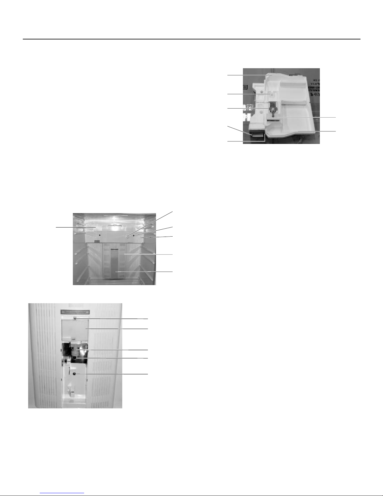
3.5 REPLACEMENT OF DAMPER THERMO
3.5.1 Remove the lamp cover.
3.5.2 Remove the multi air louver screw.
3.5.3 Remove the wiring cover.
3.5.4 Remove the multi air louver assy.
3.5.5 Remove the R control box scrwe.
3.5.6 Remove the R control box assy.
3.5.7 Remove the R air guide.
3.5.8 Remove the damper thermo and replace.
F knob
drain hole cover
screw
R control box assy
multi air louver
R air guide top
R knob sealer
screw
B-THM support
R air guide sealer
damper thermo
R air guide bottom
lamp cover
screw
wiring cover
lamp holder
lamp
screw
Page 12
III. SERVICE GUIDE
3.6 REPLACEMENT OF DOOR SWITCH
3.6.1 Remove the door switch by using
screwdriver, remove the door switch from
cabinet, takinf care not to damage the
cabinet.
door switch
3.7 REPLACEMENT OF D-TIMER
3.7.1 Remove electric box screw.
3.7.2 Remove electric box.
3.7.3 Remove D-timer and replace.
fan fan motor (for compressor)
screw
electric box
charge pipe
compressor
rating label
compressor cover
terminal
defrost timer
Page 13
III. SERVICE GUIDE
3.8 REPLACEMENT OF PTC & OLP
OVERLOAD RELAY
3.8.1 Remove the compressor cover.
3.8.2 Remove electric box clamp.
3.8.3 Remove electric box.
3.8.4 Remove PTC & OLP and replace PTC &
OLP.
OLP overload relay
start relay
electric box
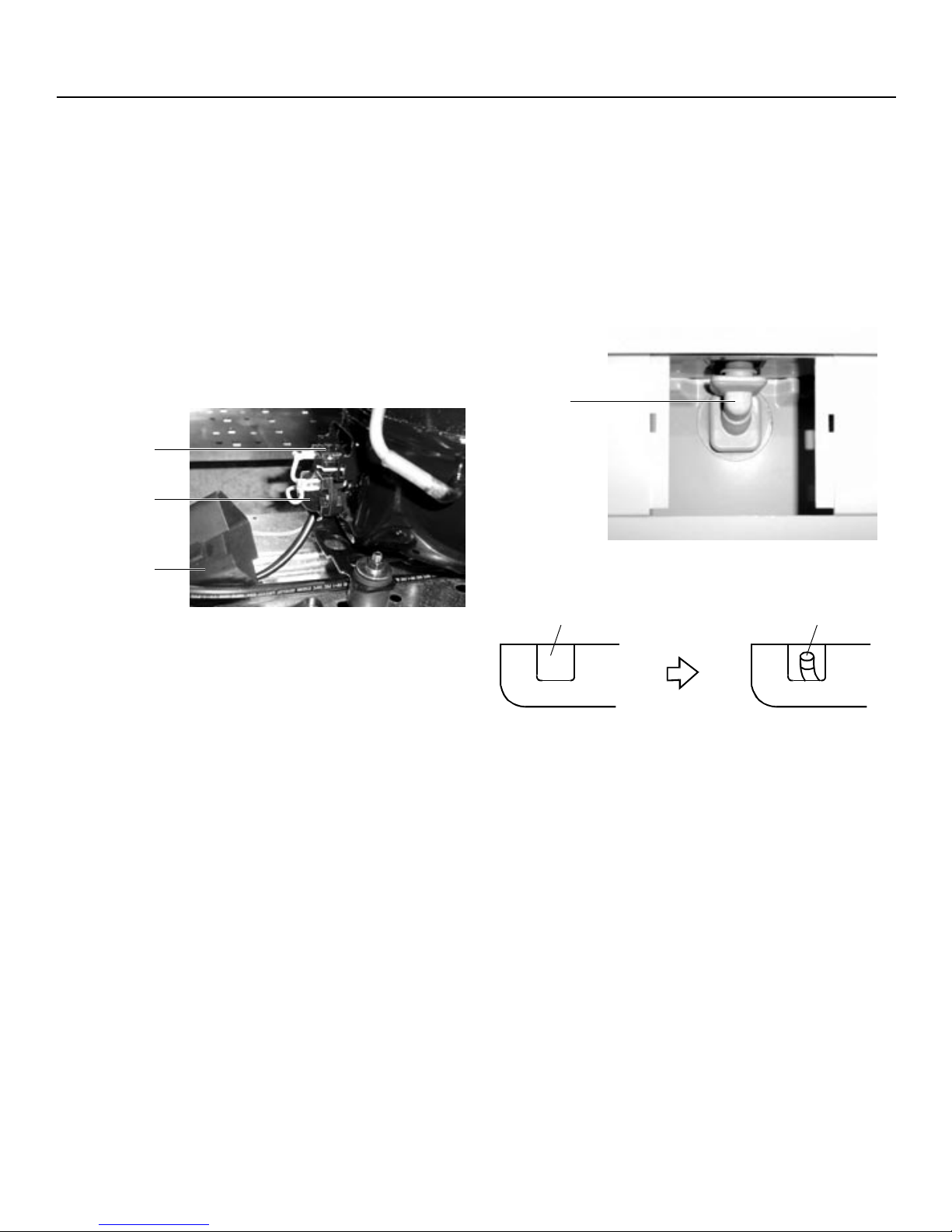
3.9 HOW TO CLEAN DRAIN PIPE
3.9.1 Remove drain hole cover.
3.9.2 Remove drain connector.
3.9.3 Clean connector & drain pipe.
drain connector
Dismounting and Cleaning of Drainage Pipe
Drainage hole cover Drainage pipe
Control box
Before opening the box After opening the box
3.9.4 Water Drainage
i. The water drainage adapter in the
drawer should be cleaned every 6
months to 1 year to keep it from being
obstructed. This avoids poor drainage
and refrigeration.
ii. The water drained from the refrigerator
is drained into the evaporation pan
from the drainage system.
iii. Water in the evaporation pan shall be
duly evaporated by the radiator. There
is no need to remove it.
iv. After some time, dust or impurity
builds up in the evaporation pan and
produces odor. This should be
cleaned once a month.
Page 14
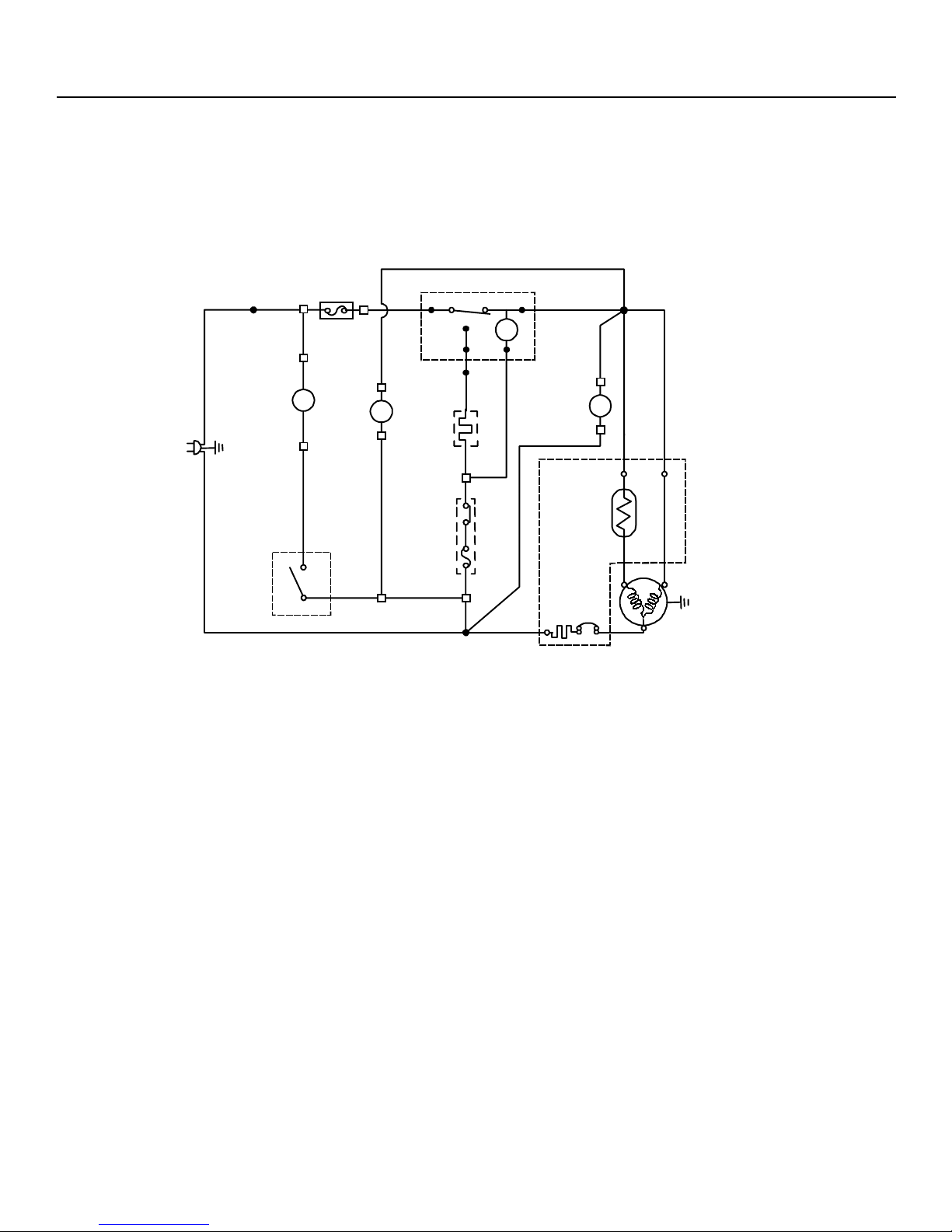
IV. WIRING DIAGRAM
Be sure to replace the electrical parts with specified ones for maintaining the safety and performance of the set. Because
these are important for maintaining the safety of the set.
BLACK
LAMP
SWITCH
BLACK
LAMP
BLUE
L
GREEN
GREEN
F-THM
FAN
MOTOR
WHITE
FM
ORANGE
TIMER
REDBLUE
21
TM
34
BROWN
BROWN
CONDENSER
FAN MOTOR
YELLOW
DEFROST
HEATER
D-THM
WHITE
GRAY GRAY
FM
P
T
C
OCR
C
56
MS
COMPRESSOR
Page 15

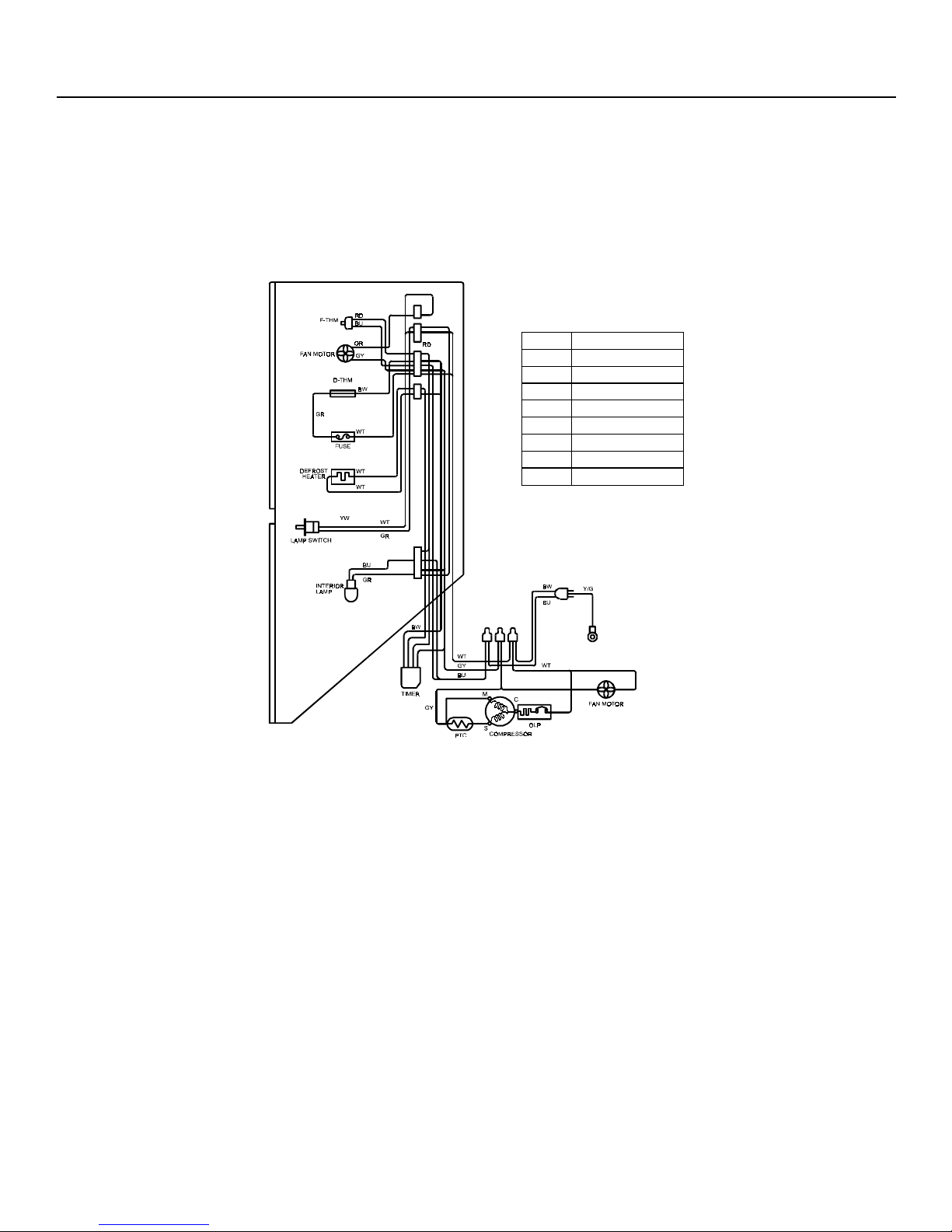
IV. WIRING DIAGRAM
PTV15SAMR / PTU427SAMR / PTQ440SAMR / PTG440SAMR
PTV16SAMR / PTU463SAMR / PTQ470SAMR / PTG470SAMR
Colour Code Table
RED
RD
BLUE
BU
BROWN
BW
ORANGE
OR
GRAY
GY
WHITE
WT
GREEN
GR
YELLOW
YW
YELLOW /GREEN
Y/G
Page 16
IV. WIRING DIAGRAM
PTV19SAMR / PTU527SAMR / PTQ530SAMR / PTG530SAMR
PTV20SAMR / PTU565SAMR / PTQ570SAMR / PTG570SAMR
Colour Code Table
RD
RED
BU
BLUE
BW
BROWN
OR
ORANGE
GY
GRAY
WT
WHITE
GR
GREEN
YW
YELLOW
Y/G
YELLOW /GREEN
Page 17

5.1 DEFROSTING
5.1.1 No Defrosting Operation Is
Necessary
As this machine is so designed that a
built-in evaporator cools air and a fan
circulates cooled air, neither the
freezer nor the refrigerator is frosted,
though the evaporator is frosted.
The frosted evaporator is defrosted
automatically due to the function of
defrosting timer and heater, requiring
no defrosting operation.
5.1.2 Where is melted ice brought?
i. Melted ice is brought into the
V. FUNCTIONS
evaporating pan at the bottom of
the set and is evaporated here by
the heat of sub condenser.
ii. Be sure to use the evaporating pan
as inserted so as to be level with
the outer case.
Page 18
V. FUNCTIONS
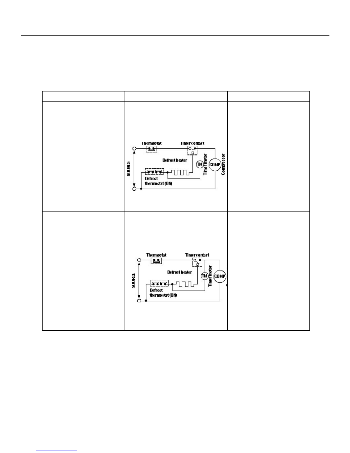
5.1.3 The following circuit diagrams in the table show automatic defrosting function of the refrigerator
with timer and defrost thermostat.
Operation Electric diagram Description
Defrost thermostat ON
1. Cooling (Normal)
·
Compressor running
·
Timer motor running
·
The integration timer
integrates running time of
the compressor. When it
reaches 8 hours 50 min. at
50Hz (10 hours 50 min at
60Hz), the timer contact is
changed to start
defrosting.
2. Defrosting
(Time 20 to 30 min)
Figure F-1
Defrost thermostat ON
·
Compressor stops
·
Timer motor stops
·
Figure F-2
The timer contact is
·
changed to start
defrosting, the timer
motor stops, and power
is supplied to the defrost
heater.
It takes about 20 to 30
·
min. to defrost. When
little frosted the
defrosting takes little
time. When much
frosted, the defrosting
takes much time.
Page 19
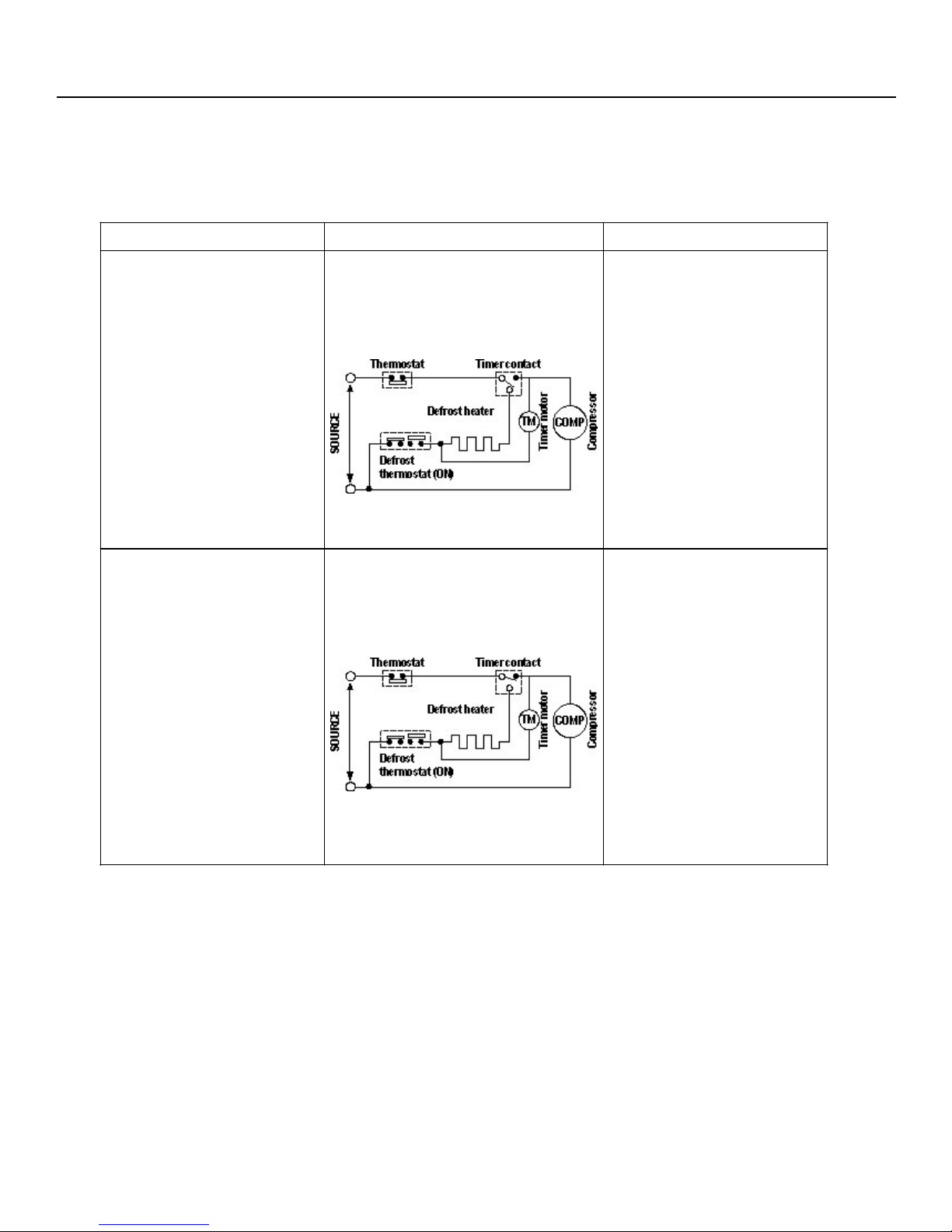
Operation Electric diagram Description
3. Drain
(Time approx. 3 min)
V. FUNCTIONS
Defrost thermostat OFF
·
Compressor stops
·
Timer motor running
·
Figure F-3
When the defrost
thermostat becomes OFF,
the timer motor at rest
starts running. During the
operation time (2 min. 48
sec./50Hz; 2 min/ 60Hz)
defrosted water is drained
outside the refrigerator.
4. Cooling start
(Time approx. 5 min)
Defrost thermostat OFF
·
Compressor running
·
Timer motor stops
·
Figure F-4
Timer contact is
·
changed to cooling
operation and the
compressor starts
running and the timer
motor stops.
Defrost thermostat
·
contact becomes ON
when its cooled. (Figure
F-1)
Page 20

V. FUNCTIONS
5.1.4 As a reference to determine the
causes of trouble, malfunction and
phenomena are described. Refer to
the following when repairing
i. Disconnection
As off-cycle defrosting is performed,
the defrosting time is extremely
prolonged. Each time defrostihg is
started, the freezer temperature rises
and a portion of ice and stored foods
are melted.
ii. Melted thermo. fuse or opened-circuit
due to the defect of defrost thermostat
When the above mentioned trouble
occurs in cooling operation, the timer
motor does not run, defrosting will not
take place, and consequently freezing
is caused. In the above mentioned
condition, when the timer shaft is
turned by hand to defrost, the timer
motor runs during the operation time.
However, the motor stops from thetime when the contact is changed,
and freezing causes.
Note :
As the thermo. fuse assembly is
intended to prevent dangers, do not use
it under shorted condition even for a
short period.
Page 21
5.2 DEW PREVENTION
The hot pipe, namely D.P. -condenser, is arranged
around the flange part of cabinet and the C-partition
plate, preventing dew from being generated on the
cabinet.
i. D.P. condenser pipe may be felt hot if
touched by hand while the compressor
is in operation.
ii. If you are asked about this, please
explain that the hot pipe serve to prevent
the dew generation.
V. FUNCTIONS
Hot pipe
Page 22

V. FUNCTIONS
5.3 INSPECTION OF INITIAL STARTING
5.3.1 Inspection of cooling unit
i. Set the temperature control knob to
MAX and check that the compressor
starts to operate.
ii. Check that cool air is blown out of
the cold air outlet of the freezer and
the refrigerator.
iii. When the compressor does not work,
check that the timer is not set to
defrost-position.
iv. It takes about an hour and a half or
two hours to put food in the refrigerator
after starting operation.
Note :
- After return the temperature control
knob to MED position.
5.3.2 Inspection of defrost device
Operate the refrigerator for 20 to 30 min.
and then check the defrost device in the
following procedures. Allow 5 min. to
restart the compressor since immediate
starting after stopping will cause
unsmooth operation.
i. Turn the timer shaft clockwise with a
screw driver. At this time, make
certains the timer clinks and the
compressor stops.
ii. After more than 5 min., turn the shaft
further to operate. Make certain
cooling operation is started again.
Note :
- Its not necessary to switch the timer
by changing of source frequency
(50Hz, 60Hz).
- When the refrigerator is operated
initially after installed, the compressor
may vibrate excessively for 1 to 2 min.
However, vibration becomes normal if
it is continuously operated.
Page 23
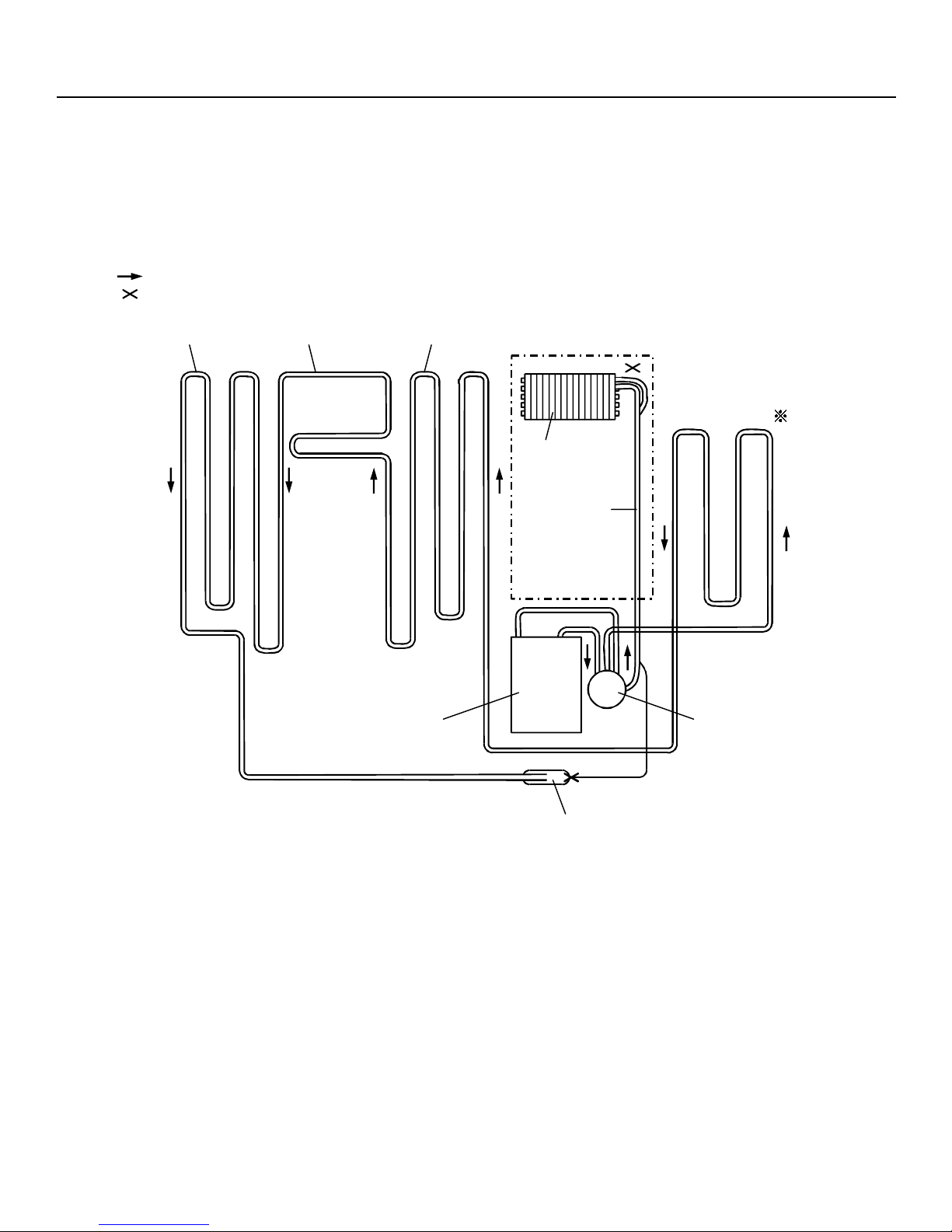
Mark: Refrigerant flow
Mark: Brazing portion
VI. COOLING UNIT
(Side condenser)
Hot pipe
(DP-condenser) (Side condenser)
Bottom condenser
Back condenser
Evaporator
Suction pipe
Compressor
Capillary tube
Dryer
Figure 1 - Cooling Unit
Page 24

VII. ADJUSTMENT
7.1 COMPRESSOR
7.1.1 Role
The Compressor inhales low temp.
and low pressure gas evaporated from
Evaporator of the refrigerator, and
condenses this gas to high temp. and
high pressure gas, and then plays
delivering role to Condenser.
7.1.2 Composition
The compressor is composed of
Compressor Apparatus compressing
gas, Compressor Motor moving
Compressor Apparatus and Case
protecting Compressor Apparatus and
Motor.
There are PTC-Starter, and Over Load
Protector in the Compressor outside.
On the other hand, because the
Compressor consists of 111000 mm
processing precision components and
is sealed after producing without dust
or humidity, deal and repair with care.
7.1.3 Note to Use
i. Be careful not to allow over voltage and
over current.
ii. No Strike:
If applying forcible power or strike
(dropping or careless dealing), poor
operation and noise may occur.
iii. Use proper electric components
appropriate to the compressor.
iv. Note to Keep Compressor:
If Compressor gets wet in the rain and
rust in the pin of Hermetic Terminal, poor
operation and poor contact may cause.
v. Be careful that dust, humidity, and flux
due to welding dont inflow in Compressor
inside in replacing Compressor. Dust,
humidity, and flux due to welding which
inflows to Cylinder may cause lock and
noise.
Page 25

VII. ADJUSTMENT
7.2 PTC-STARTER
7.2.1 Composition of PTC-Starter
i. PTC (Positive Temperature Coefficient)
is no-contact semiconductor starting
device which uses ceramic material
and the material consists of BaTiO3.
ii. The higher the temperature is, the
higher resistance value becomes.
These features are used as starting
device of motor.
7.2.2 Role of PTC-Starter
i. PTC is attached to hermetic
Compressor used for refrigerator,
show case and starts motor.
ii. Compressor for household refrigerator
applies singlephase induction motor.
For normal operation of singlephase
induction motor, in the starting
operation flows in both main coil and
sub coil. After the starting is over, the
current is cut off in sub coil. The
proper features of PTC play the above
all roles. So, PTC is used as a starting
device of motor.
7.2.4 Relation of PTC-Starter and OLP
i. If power off during operation of
Compressor and power on before PTC
is cooled, (instant shut-off within 2
min, or reconnect a power plug due
to misconnecting), PTC isnt cooled
and a resistance value grows. As a
result, current cant flow to the subcoil and motor cant operate and OLP
operates by flowing over current in
only main-coil.
ii. While the OLP repeats on and off
operation about 3-5 times, PTC is
cooled and Compressor Motor
performs normal operation.
iii. If OLP doesnt operate when PTC is
not cooled, compressor motor is worn
away and causes circuit-short and fire.
Therefore, use a proper fixed OLP
without fail.
7.2.5 Note to Use PTC-Starter
i. Be careful to over voltage and over
current.
ii. No Strike:
7.2.3 Motor Restarting and PTC Cooling
i. For restarting after power off during
normal Compressor Motor operation,
plug the power cord after 5 min. for
pressure balance of refrigerating cycle
and PTC cooling.
ii. During normal operation of
Compressor Motor, PTC elements
generate heat continuously. Therefore,
if PTC isnt cooled for a while after
power off, Motor cant operate again.
Dont apply a forcible power or strike.
iii. Keep apart from any liquid. If liquid
such as oil or water inflows into PTC,
PTC materials may break due to
insulation breakdown of material itself.
iv. Dont change PTC at your
convenience. Dont disassemble PTC
and mold. If damaging to outside of
PTGStarter, resistance value alters
and poor starting of Compressor
motor may cause.
v. Use a properly fixed PTG.
Page 26
 Loading...