

Page 1
Installation
Instructions
If you have any questions, call GE Appliances at 800.GE.CARES
(800.432.2737) or visit our Website at: GEAppliances.com
In Canada, call 800.561.3344 or visit www.GEAppliances.ca
BEFORE YOU BEGIN
Read these instructions completely and carefully.
Dryer
• IMPORTANT – Save these instructions for
local electrical inspector’s use.
• IMPORTANT – Observe all governing
codes and ordinances.
• Install the clothes dryer according to the
manufacturer’s instructions and local codes.
• Note to Installer – Be sure to leave these
instructions with the Consumer.
• Note to Consumer – Keep these instructions for
future reference.
• Clothes dryer installation must be performed by a
qualified installer.
• This dryer must be exhausted to the outdoors.
• Before the old dryer is removed from service or
discarded, remove the dryer door.
• Service information and the wiring diagram are
located in the control console.
• Do not allow children on or in the appliance. Close
supervision of children is necessary when the
appliance is used near children.
• Proper installation is the responsibility of the installer.
• Product failure due to improper installation is not
covered under the Warranty.
• Install the dryer where the temperature is above
50°F for satisfactory operation of the dryer control
system.
• Remove and discard existing plastic or metal foil
duct and replace with UL-listed duct.
- Risk of Fire
• Clothes dryer installation must be performed by a
qualified installer.
• Install the clothes dryer according to these
instructions and local codes.
• DO NOT install a clothes dryer with flexible plastic
venting materials. If flexible metal (semi-rigid or
foil-type) duct is installed, it must be UL-listed and
installed in accordance with the instructions found
in “Connecting the Dryer to House Vent” later in
this manual. Flexible venting materials are known
to collapse, be easily crushed and trap lint. These
conditions will obstruct dryer airflow and increase
the risk of fire.
• DO NOT install or store this appliance in any
location where it could be exposed to water or
weather.
• To reduce the risk of severe injury or death, follow
all installation instructions.
• Save these instructions. (Installers: Be sure to
leave these instructions with the customer.)
FOR GAS DRYERS ONLY
In the Commonwealth of Massachusetts,
the following installation instructions apply:
• Installation must be performed by a qualified or
licensed contractor, plumber, or gasfitter qualified
or licensed by the State.
• If using a ball valve, it shall be a T-handle type.
• A flexible gas connector, when used, must not
exceed 4 feet (1.2 m).
31-3000245-3
01-22 GEA
Page 2
Installation Instructions
UNPACKING YOUR DRYER
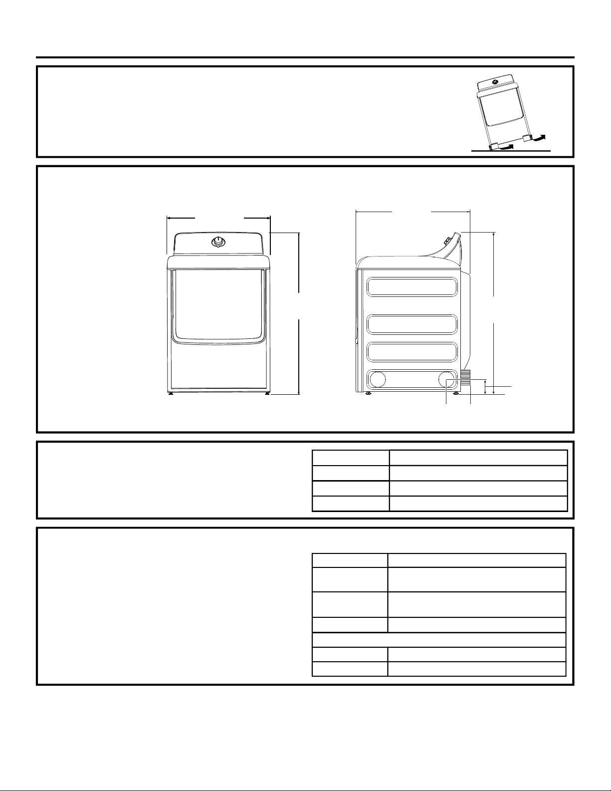
Tilt the dryer sideways and remove the foam shipping pads by pulling at the sides and
breaking them away from the dryer legs. Be sure to remove all of the foam pieces around
the legs.
Remove the bag containing the literature.
DRYER
DIMENSIONS
27”
(68.8 cm)
31”
(79 cm)
43 7/8”
(112 cm)
Front View
ACCESSORIES:
Order on-line at GEApplianceparts.com, 24 hours a day or
by phone at 877.959.8688 during normal business hours.
Part Number Accessory
PM14X10056
WX14X10007
PM08X10085
STEAM WATER HOSES (for steam dryer models only):
GE Appliances strongly recommends the use of factory
specified parts. These hoses are manufactured and tested
to meet GE Appliances specifications.
GE Appliances strongly recommends the use of new water
supply hoses. Hoses degrade over time and need to be
replaced every 5
and water damage.
Parts and Accessories
Order on-line at GEApplianceparts.com, 24 hours a day
or by phone at 877.959.8688 during normal business hours.
years to reduce the risk of hose failures
Part Number Accessory
WE25X20060
WE49X25794
WE1M847 Long Hose
OR SEPARATELY
WE1M847 Long Hose and
WE1M848 Short Hose
43 7/8”
(112 cm)
4 5/8”
Side View
4 1/4”
(10.8 cm)
Dryer Door Opening Vent Brush
LintEater™ Dryer Rotary Tube Brush
Flexible Metal Dryer Transition Duct
Complete Kit (hoses, Y-adapter, washers)
or
Kit (Short hose, Y-adapter, washers)
and
(11.7 cm)
2
Page 3
Installation Instructions
REQUIREMENTS FOR ALCOVE OR
CLOSET INSTALLATION
- Explosion Hazard
Keep flammable materials and vapors, such as gasoline,
away from dryer.
Place dryer at least 18” (46 cm) above the floor for a
garage installation.
Failure to do so can result in death, explosion, or fire.
• The dryer MUST be vented to the outdoors.
• Minimum clearance between dryer cabinet and
adjacent walls or other surfaces is:
0” (0 cm) either side*
1” (2,54 cm) front
1” (2,54 cm) rear
1”
* For improved performance, a 1/2” (12.7 mm)
clearance is suggested on each side.
• The rear of the dryer should face a wall.
• Consideration must be given to provide adequate
clearance for installation and service.
• Closet doors must be louvered or otherwise
ventilated and have at least 60 square inches (387
cm2) of open area. If the closet contains both a
washer and a dryer, doors must contain a minimum
of 120 square inches (774 cm2) of open area.
NOTE: WHEN THE EXHAUST DUCT IS LOCATED AT
THE REAR OF THE DRYER, THE CONFIGURATION
OF THE DUCTING MAY REQUIRE GREATER
CLEARANCE.
Gas Dryers Only:
• No other fuel burning appliance shall be installed in
the same closet as a gas dryer.
• The dryer must be disconnected from the gas
supply piping during pressure testing at pressures
greater than 1/2 psi (3.5 kPa).
• A 1/8” (3.2 mm) NPT minimum plugged tapping,
accessible for test gauge connection, must be
installed immediately upstream of the gas supply
connection to the dryer.
(2,54 cm)
top
MINIMUM CLEARANCE OTHER
THAN ALCOVE OR CLOSET
INSTALLATION
Minimum clearance to combustible surfaces and for
air opening are: 0” (0 cm) both sides*, 1” (2,54 cm)
rear and 1” (2,54 cm) top.
* For improved performance, a 1/2” (12.7 mm)
clearance is suggested on each side.
The rear of the dryer should face a wall.
Consideration must be given to provide adequate
clearance for installation and service.
MOBILE OR MANUFACTURED
HOME INSTALLATION
• Installation MUST conform to the
MANUFACTURED HOME CONSTRUCTION
AND SAFETY STANDARD, TITLE 24, PART
3280 or STANDARD FOR MOBILE HOMES
CAN/CSA-Z240 MH, or, when such standards
are not applicable, with AMERICAN NATIONAL
STANDARD FOR MOBILE HOME, ANSI/NFPA
NO. 501B.
• The dryer MUST be vented to the outdoors.
• The exhaust vent MUST be securely fastened to a
non-combustible portion of the mobile home.
• The vent MUST NOT be terminated beneath a
mobile or manufactured home.
• The vent duct material MUST BE METAL.
• KIT 14-D346-33 MUST be used to attach the dryer
securely to the structure.
• The vent MUST NOT be connected to any other
duct, vent or chimney.
• DO NOT use sheet metal screws or other
fastening devices which extend into the interior of
the exhaust vent.
• Provide an opening with a free area of at least 25
square inches (63 cm2) for introduction of outside
air into the dryer room.
• See the sections for electrical connection information.
3
Page 4
Installation Instructions
CONNECTING INLET HOSES (for steam dryer models only)
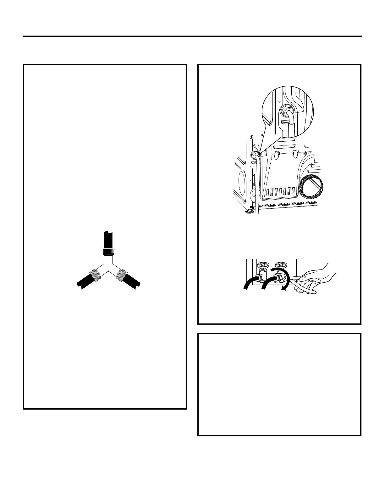
CONNECTING INLET HOSES
To produce steam, the dryer must connect to the cold
water supply. Since the washer must also connect to
the cold water, a “Y” connector is inserted to allow
both inlet hoses to make that connection at the same
time.
NOTE: Use new inlet hoses; never use old hoses.
1. Turn the cold water faucet off. Remove the washer
inlet hose from the washer fill valve connector
(cold).
2. Ensure the rubber flat washer is in place and attach
one female coupling of the short hose provided
onto the washer fill valve connector. Tighten by
hand until firmly seated.
3. Attach one male end of the “Y” connector to the
other female coupling of the short hose. Ensure the
rubber flat washer is in place. Tighten by hand until
firmly seated.
CONNECTING INLET HOSES (cont.)
7. Using pliers, tighten all the couplings with an
additional two–thirds turn.
NOTE: Do not overtighten. Damage to the couplings
may result.
4. Insert the filter screen in the coupling of the
washer’s inlet hose. If a rubber flat washer is
already in place remove it before installing the filter
screen. Attach this coupling to one male end of the
‘’Y’’ connector. Tighten by hand until firmly seated.
5. Ensure the rubber flat washer is in place and attach
a 4 ft. (1.2 m) to 6 ft. (1.8 m) long water inlet hose
(may need to be purchased separately) to one male
end of the ‘’Y’’ connector. Tighten by hand until
firmly seated.
6. Ensure the rubber flat washer is in place and attach
the other end of the dryer’s long inlet hose to the
fill valve connector at the bottom of the dryer back
panel. Tighten by hand until firmly seated.
8. Turn the water faucet on.
9. Check for leaks around the ‘’Y’’ connector, faucet
and hose couplings.
WATER SUPPLY REQUIREMENTS
Hot and cold water faucets MUST be installed within
42 in. (107 cm) of your washer’s water inlet. The
faucets MUST be 3/4” (19.1 mm) garden hose-type
so inlet hoses can be connected. Water pressure
MUST be between 10 and 120 pounds per square
inch. Your water department can advise you of your
water pressure.
NOTE: A water softener is recommended to reduce
buildup of scale inside the steam generator if the
home water supply is very hard.
4
Page 5
Installation Instructions
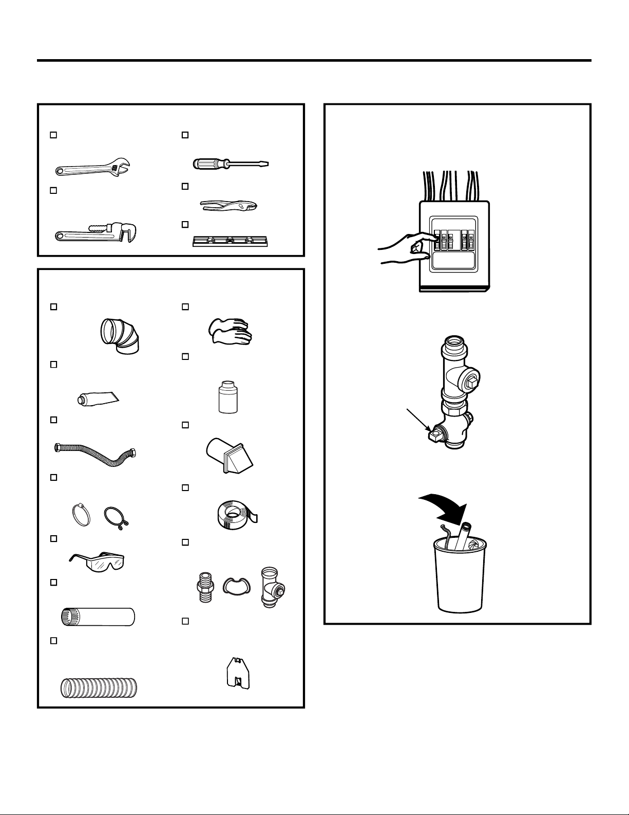
CONNECTING A GAS DRYER (skip for electric dryers)
TOOLS YOU WILL NEED
10” (25.40 cm)
Adjustable wrenches (2)
8” (20.32 cm)
Pipe wrench
Flat-blade
screwdriver
Slip-joint pliers
Level
MATERIALS YOU WILL NEED
4” (10.2 cm) dia. metal
elbow
Pipe compound or
PTFE tape
Flexible gas line
connector
Gloves
Soap solution for
leak detection
Exhaust hood
• Before beginning the installation, turn off the circuit
breaker(s) or remove the dryer’s circuit fuse(s) at
the electrical box. Be sure the dryer
cord is unplugged from the wall.
• Turn the dryer’s gas shut-off valve in the supply line
to the OFF position.
Shut-off
Valve
Duct clamps (2) or
Spring clamps (2)
Safety glasses
4” (10.2 cm) dia. metal
duct (recommended)
4” (10.2 cm) dia.,
UL-listed flexible
metal duct (if needed)
• Disconnect and discard old flexible gas connector
and ducting material.
Duct tape
Gas pipe adapters (2),
elbow and pipe plug
4” Cover Plate
(Kit WE49X22606)
(if needed)
5
Page 6
Installation Instructions
CONNECTING A GAS DRYER (cont.)
GAS REQUIREMENTS
- Explosion Hazard
• Use a new CSA International approved flexible
gas supply line. Never reuse old flexible
connectors.
• Install an individual manual shut-off valve
within 6ft. of the dryer in accordance with the
National Fuel Gas Code, ANSI Z223.1/NFPA
54.
• Securely tighten all gas connections.
• If connected to LP gas, have a qualified
person make sure gas pressure DOES NOT
exceed 13” (33 cm) water column.
• Examples of a qualified person include:
licensed heating personnel, authorized gas
company personnel, and authorized service
personnel.
• Failure to do so can result in death,
explosion, or fire.
• The installation must conform with local
codes, or in the absence of local codes, with
the National Fuel Gas Code, ANSI Z223.1/
NFPA 54, or the Natural Gas and Propane
Installation Code, CSA B149.1.
GAS SUPPLY
• A 1/8” (3.2 mm) National Pipe Taper thread
plugged tapping, accessible for test gauge
connection, must be installed immediately
upstream of the gas supply connection to the
dryer. Contact your local gas utility should you
have questions on the installation of the plugged
tapping.
• Supply line is to be 1/2” (12.7 mm) rigid pipe and
equipped with an accessible shutoff within 6 feet
(1.8 m) of, and in the same room with, the dryer.
• Use pipe thread compound appropriate for
natural or LP gas or use PTFE tape.
• Connect flexible metal connector to dryer and
gas supply.
- Fire Hazard
FOR USE WITH NATURAL GAS ONLY
Dryer as produced by manufacturer is to be used
only with a natural gas supply. A manufacturersupplied conversion kit is required to convert this
dryer for propane gas supply. Use propane
conversion kit WE25X217
. Conversion must be
made by properly trained and qualified personnel
in accordance with local codes and ordinances.
gas
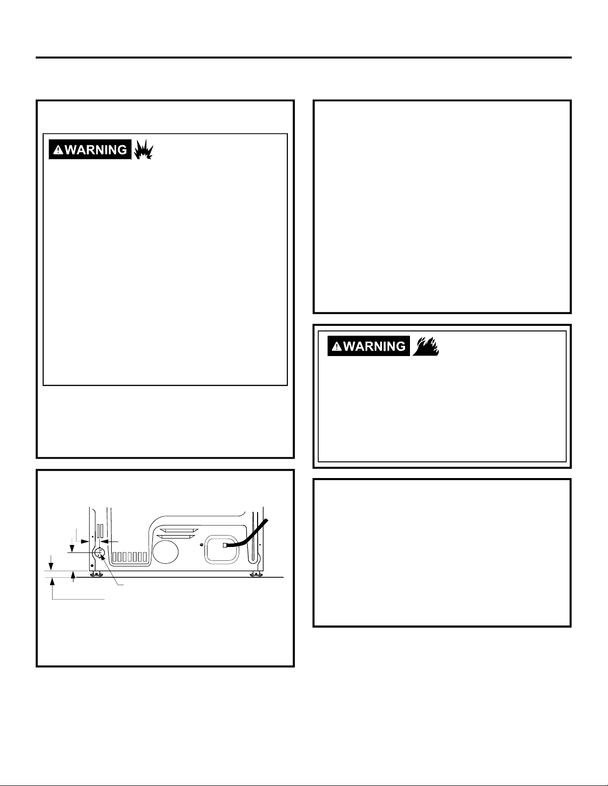
DRYER GAS SUPPLY CONNECTION
1-7/8"
3-1/8"
3/8" NPT MALE THREAD GAS SUPPLY
NOTE: Add to vertical dimension
the distance between cabinet
bottom to floor.
You must use with this dryer a flexible metal connector
(listed connector ANSI Z21.24 / CSA 6.10). The length
of the connect shall not exceed 4 ft. (1.2 m).
ADJUSTING FOR ELEVATION
• Gas clothes dryers input ratings are based on
sea level operation and need not be adjusted for
operation at or below 2000 ft. (610 m) elevation.
For operation at elevations above 2000 ft. (610 m),
input ratings should be reduced at a rate of 4
percent for each 1000 ft. (305 m) above sea level.
• Installation must conform to local codes and
ordinances or, in their absence, the NATIONAL
FUEL GAS CODE, ANSI Z223.
6
Page 7
Installation Instructions
CONNECTING A GAS DRYER (cont.)
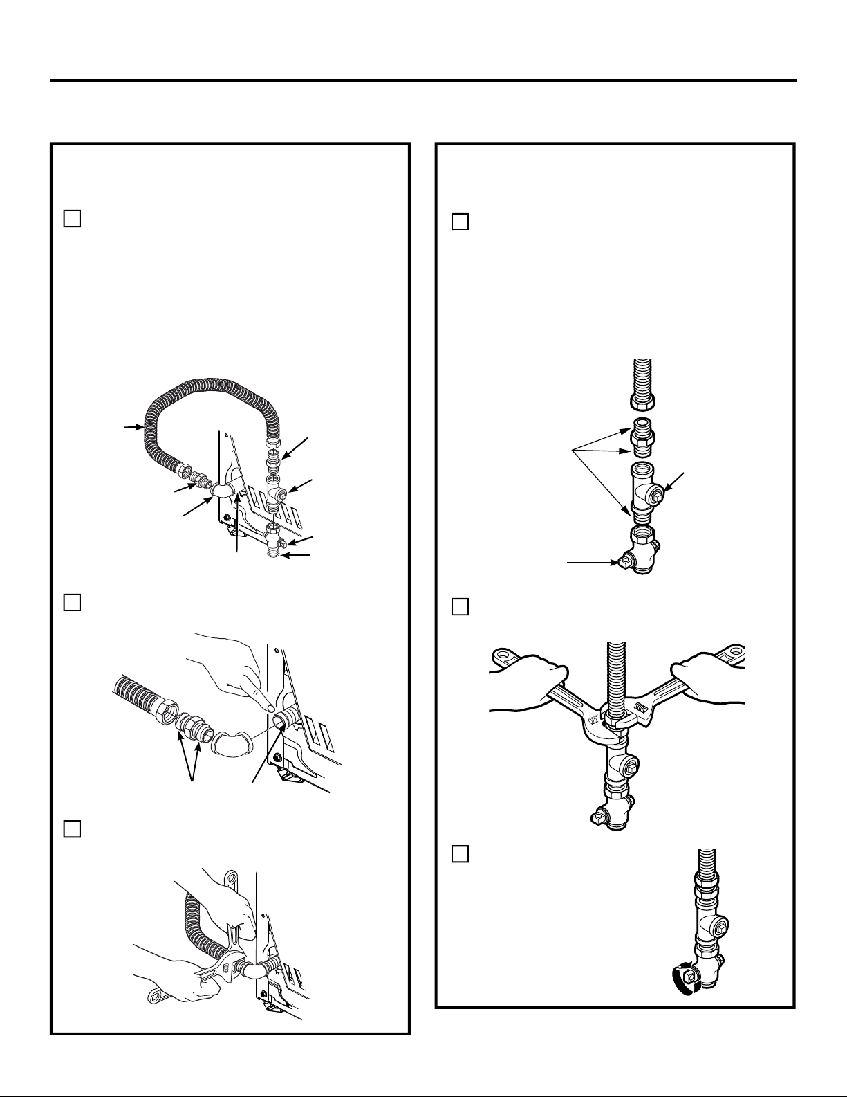
CONNECTING THE DRYER TO
THE GAS SUPPLY
Install a female 3/8” (9.6 mm) NPT elbow at
A
the end of the dryer gas inlet.
Install a 3/8” (9.6 mm) flare union adapter to
the female elbow.
IMPORTANT: Use a pipe wrench to securely
hold on to the end of the dryer gas inlet to
prevent twisting the inlet.
NOTE: Apply pipe compound or PTFE tape to
the threads of the adapter and dryer gas inlet.
New Metal
Flexible Gas
Line Connector
Adapter
Elbow
Items not supplied
3/8” NPT
Adapter
1/8” NPT
Pipe Plug for
Checking Gas
Inlet Pressure
Shut-Off Valve
Pipe size at
least 1/2”
CONNECTING THE DRYER TO
THE GAS SUPPLY (cont.)
Install a 1/8” (3.2 mm) NPT plugged tapping
D
to the dryer gas line shut-off valve for
checking gas inlet pressure.
Install a flare union adapter to the plugged
tapping.
NOTE: Apply pipe compound or PTFE tape
to the threads of the adapter and plugged
tapping.
Apply pipe compound
or PTFE tape to all
male threads.
Shut-Off
Valve
Plugged
Tapping
Attach the flexible metal gas line connector to
B
the adapter.
Apply pipe compound to the
adapter and dryer gas inlet
Tighten the flexible gas line connection, using
C
two adjustable wrenches.
Tighten all connections, using two adjustable
E
wrenches. Do not overtighten.
Open the gas shut-off valve.
F
7
Page 8
Installation Instructions
CONNECTING A GAS DRYER (cont.)
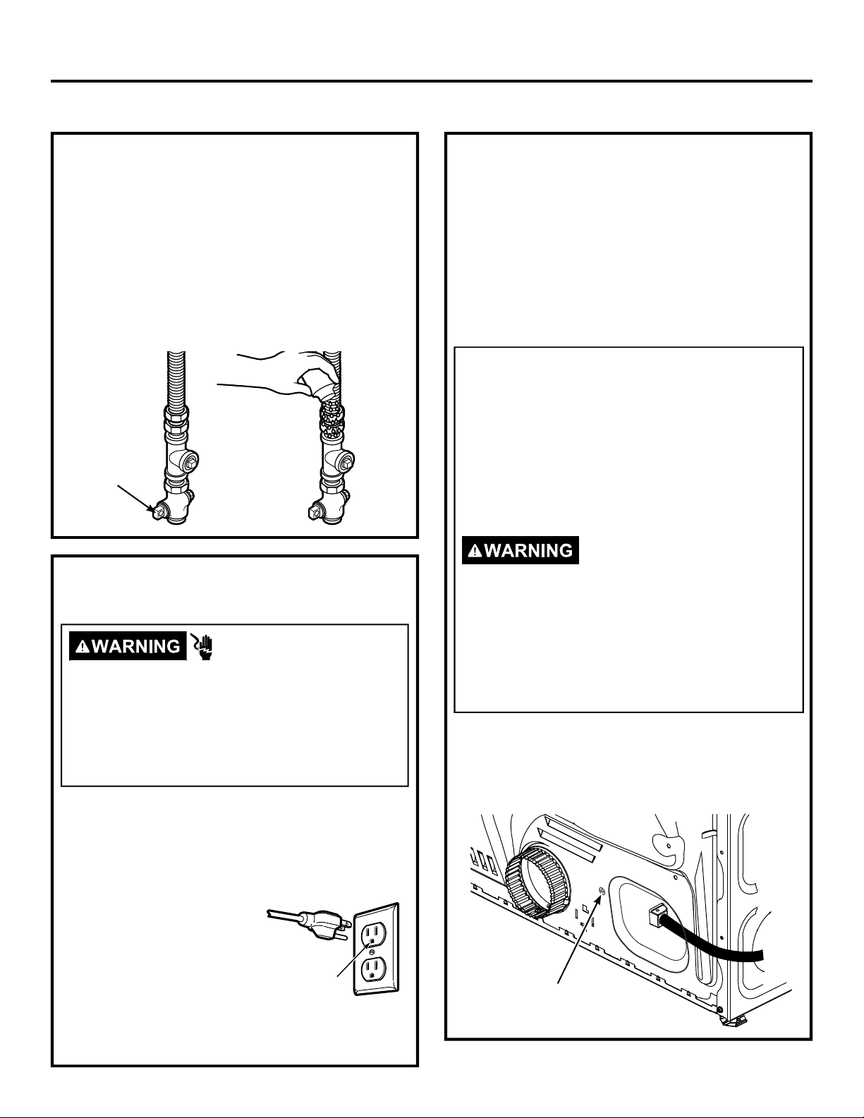
TEST FOR LEAKS
Never use an open flame to test for gas leaks.
Check all connections for leaks with soapy solution or
equivalent.
Apply a soap solution. The leak test solution must not
contain ammonia, which could cause damage to the
brass fittings.
If leaks are found, close the valve, retighten the joint
and repeat the soap test.
Open Gas
Valve
ELECTRICAL CONNECTION
INFORMATION FOR GAS DRYERS
- Electrical Shock Hazard
Plug into a grounded 3 prong outlet.
DO NOT remove ground prong.
DO NOT use an adapter.
DO NOT use an extension cord.
Failure to do so can result in death, fire or
electrical shock.
• Circuit – Individual properly polarized and grounded
15 or 20 amp circuit breaker or time-delay fuse.
• Power Supply – 2-wire plus ground, 120 Volt, single
phase, 60 Hz, alternating current.
• Outlet Receptacle – Properly grounded 3-prong
receptacle to be located
so the power cord is
accessible when the dryer
is in an installed position.
If a 2-prong receptacle is
present, it is the owner’s
responsibility to have a
licensed electrician replace
it with a properly grounded 3-prong grounding type
receptacle.
Ensure proper
ground exists
before use.
ELECTRICAL CONNECTION
INFORMATION FOR GAS DRYERS
(cont.)
• Dryer must be electrically grounded in accordance
with local codes and ordinances, or in the absence
of local codes, with the latest edition of the
NATIONAL ELECTRICAL CODE, ANSI/NFPA
NO. 70 or CANADIAN ELECTRICAL CODE, CSA
C22.1. Check with a licensed electrician if you are
not sure that the dryer is properly grounded.
GROUNDING INSTRUCTIONS
This dryer must be grounded. In the event of a
malfunction or breakdown, grounding will reduce
the risk of electric shock by providing a path of
least resistance for electric current. This dryer
uses a cord having an equipment-grounding
conductor and a grounding plug. The plug must
be plugged into an appropriate outlet that is
properly installed and grounded in accordance
with all local codes and ordinances.
Improper connection of the
equipment-grounding conductor
can result in a risk of electric shock. Check with a
qualified electrician, or service representative or
personnel, if you are in doubt as to whether the
appliance is properly grounded.
the plug on the power supply cord. If it will not
fit the outlet, have a proper outlet installed by a
qualified electrician.
SAVE THESE INSTRUCTIONS
• If required by local codes, an external 18 gauge
or larger copper ground wire (not provided) may
be added. Attach to dryer cabinet with a #8-18 x
1/2” (12.7 mm) sheet metal screw (available at any
hardware store) to rear of dryer as illustrated.
Ground
Screw
8
DO NOT
modify
Page 9
Installation Instructions
CONNECTING AN ELECTRIC DRYER
(Skip for gas dryers and if your dryer already has a power cord attached)
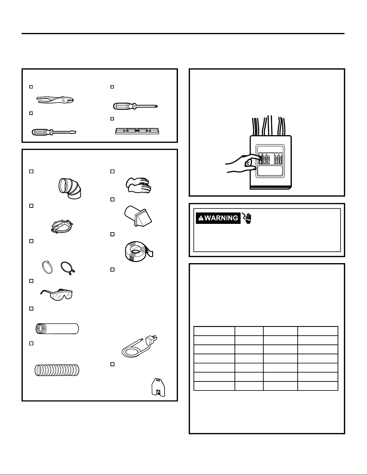
TOOLS YOU WILL NEED
Slip-joint pliers
Flat-blade
screwdriver
Phillips
screwdriver
Level
MATERIALS YOU WILL NEED
4” (10.2 cm) dia. metal
elbow
Metal strain relief clamp
(UL recognized)
4” (10.2 cm) Duct clamps
(2) or 4” (10.2 cm) spring
clamps (2)
Gloves
Exhaust hood
Duct tape
Before making the electrical connection, turn off the
circuit breaker(s) or remove the dryer’s circuit fuse(s) at
the electrical box. Be sure the dryer cord is unplugged
from the wall. NEVER LEAVE THE ACCESS COVER
OFF THE TERMINAL BLOCK.
- Electrical Shock Hazard
Disconnect power supply before servicing.
Replace all parts and panels before operating.
Failure to do so can result in death or electrical shock.
Safety glasses
4” (10.2 cm) dia. metal
duct (recommended)
4” (10.2 cm) dia.,
UL-listed flexible metal
duct (if needed)
Dryer power cord kit
(not provided with
dryer)
UL rated 120/240V,
30A with 3 or 4
prongs. Identify the
plug type as per the
house receptacle
before purchasing
line cord.
4” Cover Plate
(Kit WE49X22606)
(if needed)
POWER CORDS
GE Appliances strongly recommends the use of
factory specified parts. Select the power cord to fit your
installation requirements.
NOTE: If your dryer circuit is on a circuit protected by a
GFCI breaker, then 3-wire installation is not permitted.
House wiring and dryer must be configured for 4-wire.
Part Number Type Length Amperage
WX9X2 3-Prong 4 ft. (1.2 m) 30
WX9X3 3-Prong 5 ft. (1.5 m) 30
WX9X4 3-Prong 6 ft. (1.8 m) 30
WX9X18 4-Prong 4 ft. (1.2 m) 30
WX9X19 4-Prong 5 ft. (1.5 m) 30
WX9X20 4-Prong 6 ft. (1.8 m) 30
Order on-l ine a t GEApplianceparts.com today,
24 hours a day or by phone at 877.959.8688 during
normal business hours. In Canada, visit your local
GE Appliances parts distributor or call 800.661.1616
GEAppliances.ca/en/products/parts-filters-accessories
or
.
9
Page 10
Installation Instructions
ELECTRICAL CONNECTION
INFORMATION FOR ELECTRIC DRYERS
For electrical connections using a
power cord:
NOTE: If your dryer circuit is on a circuit protected by a
GFCI breaker, then 3-wire installation is not permitted.
House wiring and dryer must be configured for 4-wire.
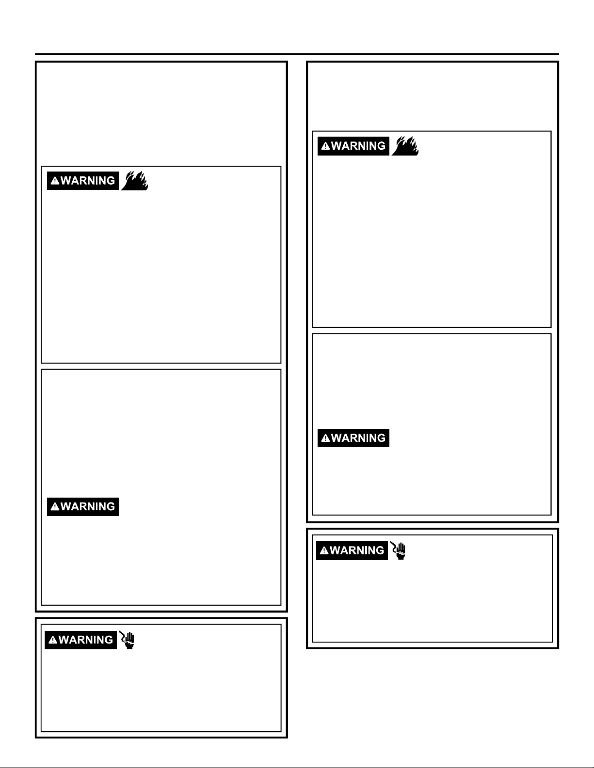
- Fire Hazard
Use a new UL-listed 240V 30 amp dryer power supply
cord with closed ring terminals or spade terminals with
upturned ends.
Use a UL-listed strain relief.
Disconnect power before making electrical connections.
Connect neutral wire (white or center wire) to center
terminal.
Ground wire (green or bare wire) must be connected to
green ground connector.
Connect remaining two supply wires to remaining two
terminals.
Securely tighten all electrical connections.
Replace the terminal block cover.
Failure to do so can result in death, fire or electrical shock.
GROUNDING INSTRUCTIONS
For a grounded, cord-connected dryer: This dryer
must be grounded. In the event of a malfunction or
breakdown, grounding will reduce the risk of electric
shock by providing a path of least resistance for
electric current. This dryer uses a cord having an
equipment-grounding conductor and a grounding
plug. The plug must be plugged into an appropriate
outlet that is properly installed and grounded in
accordance with all local codes and ordinances.
Improper connection of the
equipment-grounding conductor can
result in a risk of electric shock. Check with a qualified
electrician, or service representative or personnel, if
you are in doubt as to whether the appliance is properly
grounded.
cord. If it will not fit the outlet, have a proper outlet
installed by a qualified electrician.
SAVE THESE INSTRUCTIONS
DO NOT
modify the plug on the power supply
- Electrical Shock Hazard
ELECTRICAL CONNECTION
INFORMATION FOR ELECTRIC
DRYERS
For direct wire connections:
- Fire Hazard
Use 10 gauge copper wire.
Use a UL-listed strain relief.
Disconnect power before making electrical connections.
Connect neutral wire (white or center wire) to center
terminal.
Ground wire (green or bare wire) must be connected to
green ground connector.
Connect remaining two supply wires to remaining two
terminals.
Securely tighten all electrical connections.
Replace the terminal block cover.
Failure to do so can result in death, fire or electrical shock.
GROUNDING INSTRUCTIONS
For a permanently connected dryer: This dryer
must be connected to a grounded metal, permanent
wiring system, or an equipment-grounding conductor
must be run with the circuit conductors and
connected to the equipment-grounding terminal on
the appliance.
Improper connection of the
equipment-grounding conductor can
result in a risk of electric shock. Check with a qualified
electrician, or service representative or personnel, if
you are in doubt as to whether the appliance is properly
grounded.
SAVE THESE INSTRUCTIONS
- Electrical Shock Hazard
TO PREVENT ELECTRIC SHOCK, DISCONNECT
POWER BEFORE SERVICING.
This dryer should be connected to an individual branch
circuit with 10 gauge copper wire minimum through a
30 amp fuse or circuit breaker. DO NOT fuse neutral.
Use copper conductors only.
TO PREVENT ELECTRIC SHOCK, DISCONNECT
POWER BEFORE SERVICING.
This dryer should be connected to an individual branch
circuit with 10 gauge copper wire minimum through a
30 amp fuse or circuit breaker. DO NOT fuse neutral.
Use copper conductors only.
10
Page 11
Installation Instructions
CONNECTING AN ELECTRIC DRYER (cont.)
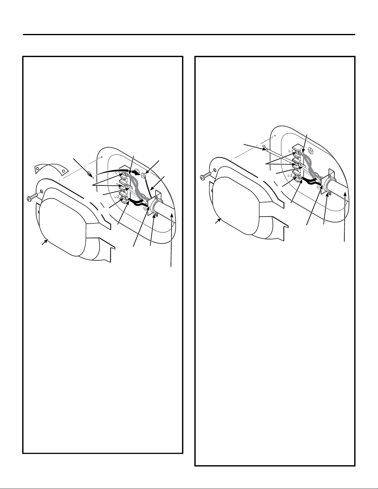
CONNECTING DRYER USING
4-WIRE CONNECTION (MUST
BE USED FOR MOBILE HOME
INSTALLATION)
NOTE: Since January 1, 1996, the National Electrical
Code requires that new constructions use a 4-wire
connection to an electric dryer. A 4-wire cord must
also be used where local codes do not permit grounding
through the neutral. 3-wire connection is NOT for use
on new construction.
Remove ground strap
and discard. Keep
green ground screw
Screws
(2)
Neutral
(white)
Screw
Cover
4 #10 AWG minimum copper conductors or 120/240V 30A power
supply cord kit marked for use with dryers and provided with closed
loop or spade terminals with upturned ends (not supplied).
1. Turn off the circuit breaker(s) (30 amp) or remove
the dryer’s circuit fuse at the electrical box.
2. Be sure the dryer cord is unplugged from the wall
receptacle.
3. Remove the power cord cover located at the lower
back.
4. Remove and discard ground strap. Keep the green
ground screw for Step 7.
5. Install 3/4” UL-recognized strain relief to power cord
entry hole. Bring power cord through strain relief.
6. Connect power cord as follows:
A. Connect the 2 hot lines to the outer screws of the
terminal block (marked L1 and L2).
B. Connect the neutral (white) line to the center of
the terminal block (marked N).
7. Attach ground wire of power cord with the green
ground screw (hole above strain relief bracket).
Tighten all terminal block screws (3) securely.
8. Properly secure power cord to strain relief.
9. Reinstall the cover.
NEVER LEAVE THE COVER OFF OF THE
TERMINAL BLOCK.
Hot
Wire
Hot
Wire
Strain
Relief
Bracket
Relocate
green
ground
screw
here
3/4” UL
Recognized
Strain Relief
Green
Wire
CONNECTING DRYER USING
3-WIRE CONNECTION
NOTE: If your dryer circuit is on a circuit protected by a
GFCI breaker, then 3-wire installation is not permitted.
House wiring and dryer must be configured for 4-wire.
If required, by local code, install external ground (not provided)
to grounded metal, cold water pipe, or other established ground
determined by a qualified electrician.
Hot
Wire
Green Ground Screw
& Ground Strap
Screws
(2)
Neutral
(white)
Screw
Hot
Wire
Cover
3 #10 AWG minimum copper conductors or 120/240V 30A power
supply cord kit marked for use with dryers and provided with closed
loop or spade terminals with upturned ends (not supplied).
Strain
Relief
Bracket
3-wire Connection
Not for use in Canada.
DO NOT use for Mobile Home Installations.
NOT for use on new construction.
NOT for use on recreational vehicles.
NOT for use in areas where local codes prohibit
grounding through the neutral conduction.
1. Turn off the circuit breaker(s) (30 amp) or remove
the dryer’s circuit fuse at the electrical box.
2. Be sure the dryer cord is unplugged from the wall
receptacle.
3. Remove the power cord cover located at lower back.
4. Install 3/4” UL-recognized strain relief to power cord
entry hole. Bring power cord through strain relief.
5. Connect power cord as follows:
A. Connect the 2 hot lines to the outer screws of
the terminal block (marked L1 and L2).
B. Connect the neutral (white) line to the center of
the terminal block (marked N).
6. Be sure ground strap is connected to neutral
(center) terminal of block and to green ground
screw on cabinet rear. Tighten all terminal block
screws (3) securely.
7. Properly secure power cord to strain relief.
8. Reinstall the cover.
NEVER LEAVE THE COVER OFF OF THE
TERMINAL BLOCK.
11
3/4” UL
Recognized
Strain Relief
Page 12
Installation Instructions
EXHAUSTING THE DRYER
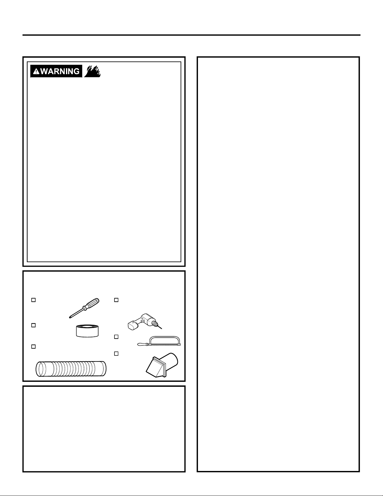
- Fire Hazard
This dryer MUST be vented to the outdoors.
Use only 4” (10.2 cm) rigid metal ducting for
the home exhaust duct.
Use only 4" (10.2 cm) rigid metal, UL-listed
flexible metal, or UL-listed metal foil dryer
transition duct to connect the dryer to the
home exhaust.
DO NOT use any plastic to vent the dryer,
this includes the home exhaust duct, dryer
transition duct, or within the dryer.
DO NOT use flexible metal or metal foil ducting
for a home exhaust duct or within the dryer.
DO NOT exhaust into a chimney, kitchen
exhaust, gas vent, wall, ceiling, attic, crawl
space, or concealed space of a building.
DO NOT install a screen in or over the exhaust
duct.
DO NOT install a booster fan in the exhaust duct.
DO NOT use duct longer than specified in the
exhaust length table.
Failure to follow these instructions can result in
death or fire.
TOOLS AND MATERIALS YOU WILL
NEED TO INSTALL EXHAUST DUCT
Phillips-head
screwdriver
Duct tape or
duct clamp
Rigid or UL-listed flexible
metal 4” (10.2 cm) duct
PARTS AVAILABLE FROM
GEAPPLIANCEPARTS.COM OR
LOCAL SERVICE ORGANIZATIONS
PM8X85
PM08X10085 8’ Flexible metal clothes dryer transition
WX08X10130 4” Dryer exhaust clamp
WE49X22606 Rear exhaust opening cover, for side or
Outdoor exhaust hood
duct with 2 clamps
bottom vented dryers
Drill with 1/8” drill bit
(for bottom venting)
Hacksaw
Vent hood
CONNECTING THE DRYER TO
HOUSE VENT
RIGID METAL TRANSITION DUCT
• For best drying performance, a rigid metal transition
duct is recommended.
• Rigid metal transition ducts reduce the risk of
crushing and kinking.
UL-LISTED FLEXIBLE METAL CLOTHES
DRYER TRANSITION DUCT
• If rigid metal cannot be used, then UL-listed flexible
metal clothes dryer transition duct (GE Appliances
part – PM08X10085) can be used.
• Never install transition duct in walls, ceilings, floors
or other enclosed spaces.
• Total length of transition duct should not exceed 8’
(2.4 m).
• For many applications, installing elbows at both
the dryer and the wall is highly recommended (see
illustrations in next section). Elbows allow the dryer
to sit close to the wall without kinking and/or crushing
the transition duct, maximizing drying performance.
• Avoid resting the duct on sharp objects.
UL-LISTED FLEXIBLE METAL (FOIL-TYPE)
TRANSITION DUCT
• In special installations, it may be necessary to
connect the dryer to the home exhaust vent
using flexible metal (foil-type) transition duct. UL–
LISTED universal flexible dryer transition duct
(GE Appliances parts – PM8X73 or WX8X73)
may be used ONLY in installations where rigid
metal or flexible metal transition ducting cannot
be used AND where a 4” (10.2 cm) diameter can
be maintained throughout the entire length of the
transition duct.
• In Canada and the United States, only transition
ducts that comply with “UL 2158A STANDARD
FOR CLOTHES DRYER TRANSITION DUCT”
shall be used.
• Avoid resting the duct on sharp objects.
• For best drying performance:
1. Slide one end of the duct over the clothes
dryer outlet pipe.
2. Secure the duct with a clamp.
3. With the dryer in its permanent position,
extend the duct to its full length. Allow 2” (5.08
cm) of duct to overlap the exhaust pipe. Cut
off and remove excess duct. Keep the duct as
straight as possible for maximum airflow.
4. Secure the duct to the exhaust pipe with the
other clamp.
12
Page 13
Installation Instructions
EXHAUSTING THE DRYER (cont.)
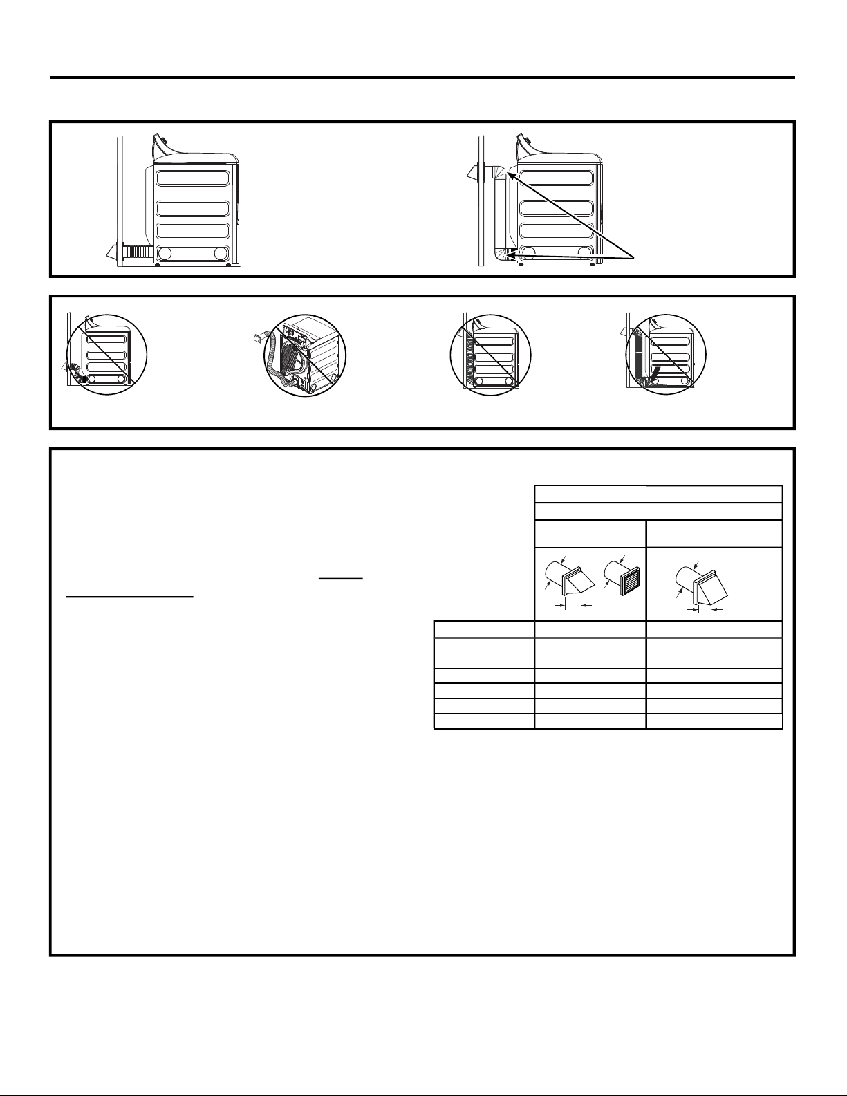
• DO cut duct as short
as possible and
install straight into
wall.
• DO NOT
bend or
collapse
ducting.
Use elbows
if turns are
• DO NOT use
excessive
exhaust
length. Cut
duct as short
as possible.
necessary.
EXHAUST LENGTH
Using exhaust longer than specified length will:
• Increase the drying times and the energy cost.
• Reduce the dryer life.
• Accumulate lint, creating a potential fire hazard.
The correct exhaust installation is YOUR
RESPONSIBILITY.
Problems due to incorrect installation are not
covered by the warranty.
The MAXIMUM ALLOWABLE length of the exhaust
system depends upon the type of duct, number of turns,
the type of exhaust hood (wall cap) and all conditions
noted on the chart.
• Internal elbows added for side or bottom vent
conversions must be included in the total elbow count.
• Any elbow greater than 45° should be treated as a 90°
elbow; one elbow of 45° or less may be ignored.
• Two 45° elbows will be treated like one 90° elbow.
• For the side exhaust installations, add one 90° elbow to
the chart.
• For every additional 90° elbow, reduce the allowable
vent system length by 10 feet (3 m).
• When calculating the total vent system length, you
must add all the straight portions and elbows of the
system (including the transition duct).
• DO use elbows
when turns are
necessary.
Elbows
• DO NOT
crush duct
against
• DO NOT
set dryer
on duct.
the wall.
RECOMMENDED MAXIMUM LENGTH
Exhaust Hood Types
Recommended
4" DIA.
No. of 90° Elbows Rigid Metal Rigid Metal
0 120 Feet (36.6 m) 90 Feet (27.4 m)
1 100 Feet (30.5 m) 75 Feet (22.9 m)
2 85 Feet (25.9 m) 65 Feet (19.8 m)
3 70 Feet (21.3 m) 55 Feet (16.8 m)
4 60 Feet (18.3 m) 45 Feet (13.7 m)
5 55 Feet (16.8 m) 35 Feet (10.7 m)
4" DIA.
4"
Use only for short run
installations
4" DIA.
2-1/2"
13
Page 14
Installation Instructions
EXHAUSTING THE DRYER (cont.)
EXHAUST SYSTEM CHECKLIST
HOOD OR WALL CAP
• Terminate in a manner to prevent back drafts or entry of
birds or other wildlife.
• Termination should present minimal resistance to
the exhaust airflow and should require little or no
maintenance to prevent clogging.
• Wall caps must be installed at least 12” (30.5 cm)
above ground level or any other obstruction with the
opening pointed down.
SEPARATION OF TURNS
• For best performance, separate all turns by at least
4 ft. (1.2 m) of straight duct, including distance
between last turn and dampened exhaust hood
(wall cap).
SEALING OF JOINTS
• All joints should be tight to avoid leaks. The male end
of each section of duct must point away from the dryer.
• Duct joints should be made air- and moisture-tight
by wrapping the overlapped joints with duct tape or
aluminum tape.
• Do not assemble ductwork with any fasteners that
extend into the duct. These fasteners can accumulate
lint, creating a potential fire hazard.
• Horizontal runs should slope down towards the
outdoors 1/4” (6.4 mm) per foot.
• Provide an access for inspection and cleaning of
the exhaust system, especially at turns and joints.
Exhaust system shall be inspected and cleaned at
least once a year.
INSULATION
• Ductwork that runs through an unheated area or is
near air conditioning should be insulated to reduce
condensation and lint build-up.
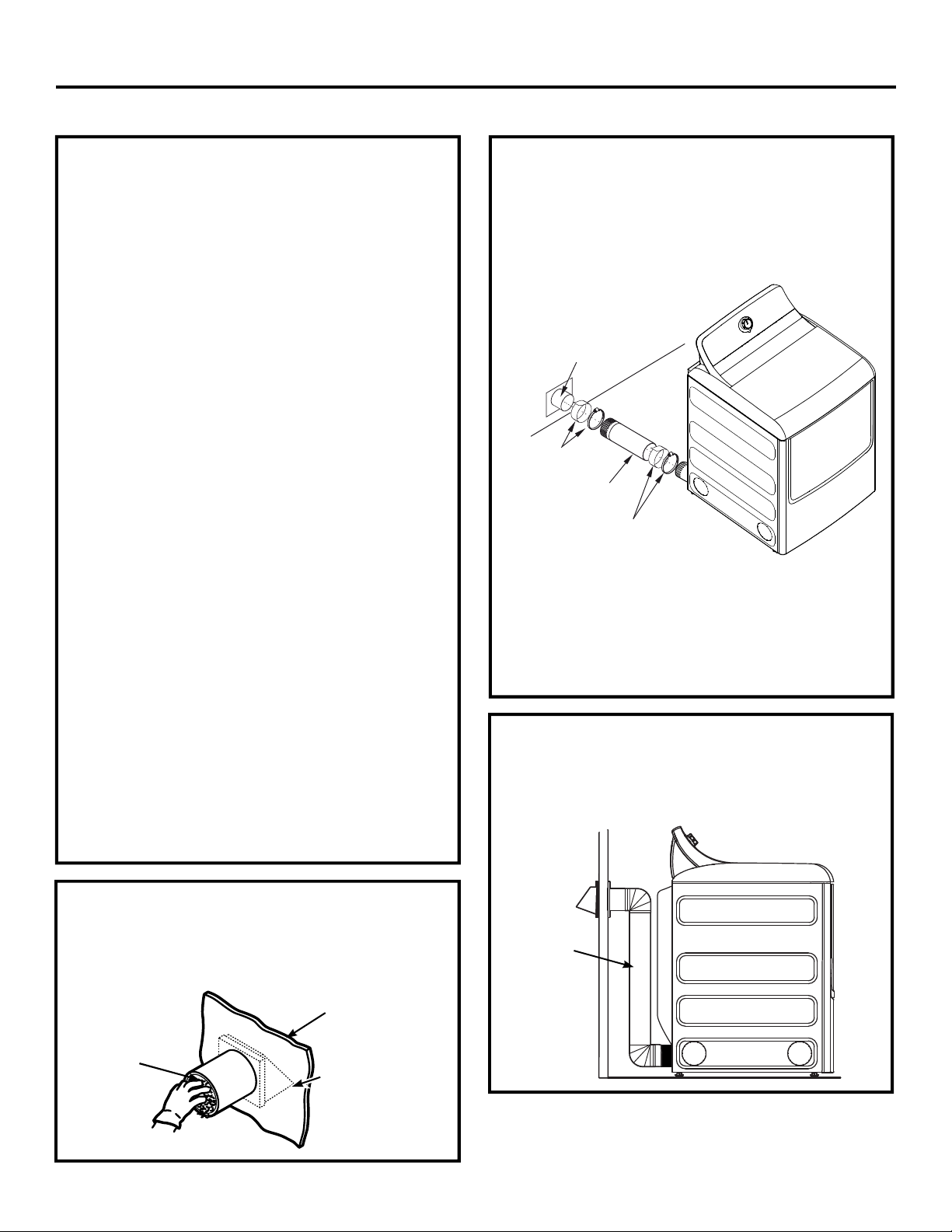
STANDARD REAR EXHAUST
We recommend that you install your dryer before
installing your washer. This will permit direct
access for easier exhaust connection.
Slide the end of the exhaust duct on the back of the
dryer and secure with duct tape or a hose clamp.
External duct
opening
Duct tape or
duct clamp
4" Metal duct cut
to proper length
Duct tape or
duct clamp
NOTE: We strongly recommend using rigid metal
exhaust duct. However, if flexible ducting is used it
must be UL-Listed metal, not plastic.
• For straight line installation, connect the dryer
exhaust to the external exhaust hood using duct
tape or clamp.
RECOMMENDED CONFIGURATION
TO MINIMIZE EXHAUST BLOCKAGE
Using duct elbows will prevent duct kinking and
collapsing.
BEFORE YOU BEGIN
• Remove and discard existing plastic or metal foil
duct and replace with UL-listed duct.
• Remove any lint from the wall exhaust opening.
Wall
Internal
Duct
Opening
Check that exhaust
hood damper
opens and closes
freely.
Transition
Ducting
14
Page 15
Installation Instructions
EXHAUSTING THE DRYER (cont.)
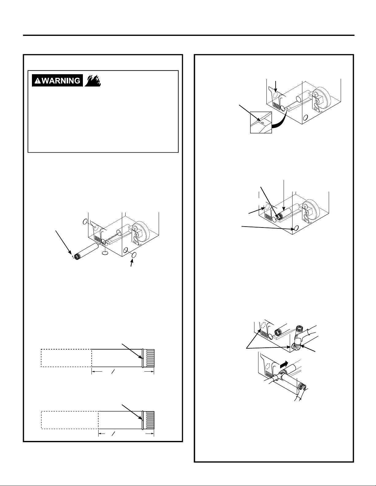
SIDE OR BOTTOM VENTING
- Fire Hazard
Disconnect dryer from electrical supply.
Wear gloves and arm guards.
Close the back opening with cover plate (Kit
WE49X22606).
Failure to do so may result in fire, electrical
shock or lacerations.
Dryer Exhaust to right of the cabinet for Electric
models only.
Dryer Exhaust to left of the cabinet for Gas and
Electric models.
Dryer Exhaust to the bottom of cabinet for Gas
and Electric models.
Remove
screw
and save
Right
(electric
models
only)
Bottom
Remove desired
knockout (one only)
Left
SIDE OR BOTTOM VENTING (cont.)
TAB LOCATION
Bend tab
up 45°
Through the rear opening, locate the tab in the middle
of the appliance base. Lift the tab to about 45°, using
a flat-blade screwdriver.
ADDING A NEW DUCT
Fixing hole
Right
Right (electric
models only)
or left side
exhaust
Reconnect the cut portion (A) of the duct to the blower
housing. Make sure that the shortened duct is aligned
with the tab in the base. Use the screw saved previously
to secure the duct in place through the tab on the
appliance base.
Not for gas models
Left
Portion “A”
Left
Detach and remove the right (electric models only),
left or bottom knockout as desired. Remove the
screw inside the dryer exhaust duct and save.
Pull the duct out of the dryer.
Cut the duct as shown and keep portion A.
For 7.4 cu. ft. models only, use the dimension
below:
Fixing hole
A
1
10
2” (26.67cm)
For 6.2 and 7.2 cu. ft. models only, use the dimension
below:
Fixing hole
A
1
9
2” (24.13cm)
ADDING ELBO W AND DU CT FOR
EXHAUST TO R IGHT (ELECTR IC
MODELS ONLY) OR LEFT SIDE OF
CABINET
Right
Exhaust can be
added to right
(electric models
only) or left side
Left
• Preassemble 4” elbow with 4” duct. Wrap duct tape
around joint.
• Insert duct assembly, elbow first, through the side
opening and connect the elbow to the dryer internal
duct.
Be sure not to pull or damage the electrical
wires inside the dryer when inserting the duct.
15
Duct
tape
Page 16
Installation Instructions
EXHAUSTING DRYER (cont.)
SIDE OR BOTTOM VENTING (cont.)
ADDING ELBOW AND DUCT FOR
EXHAUST TO LEFT OR RIGHT SIDE OF
CABINET (cont.)
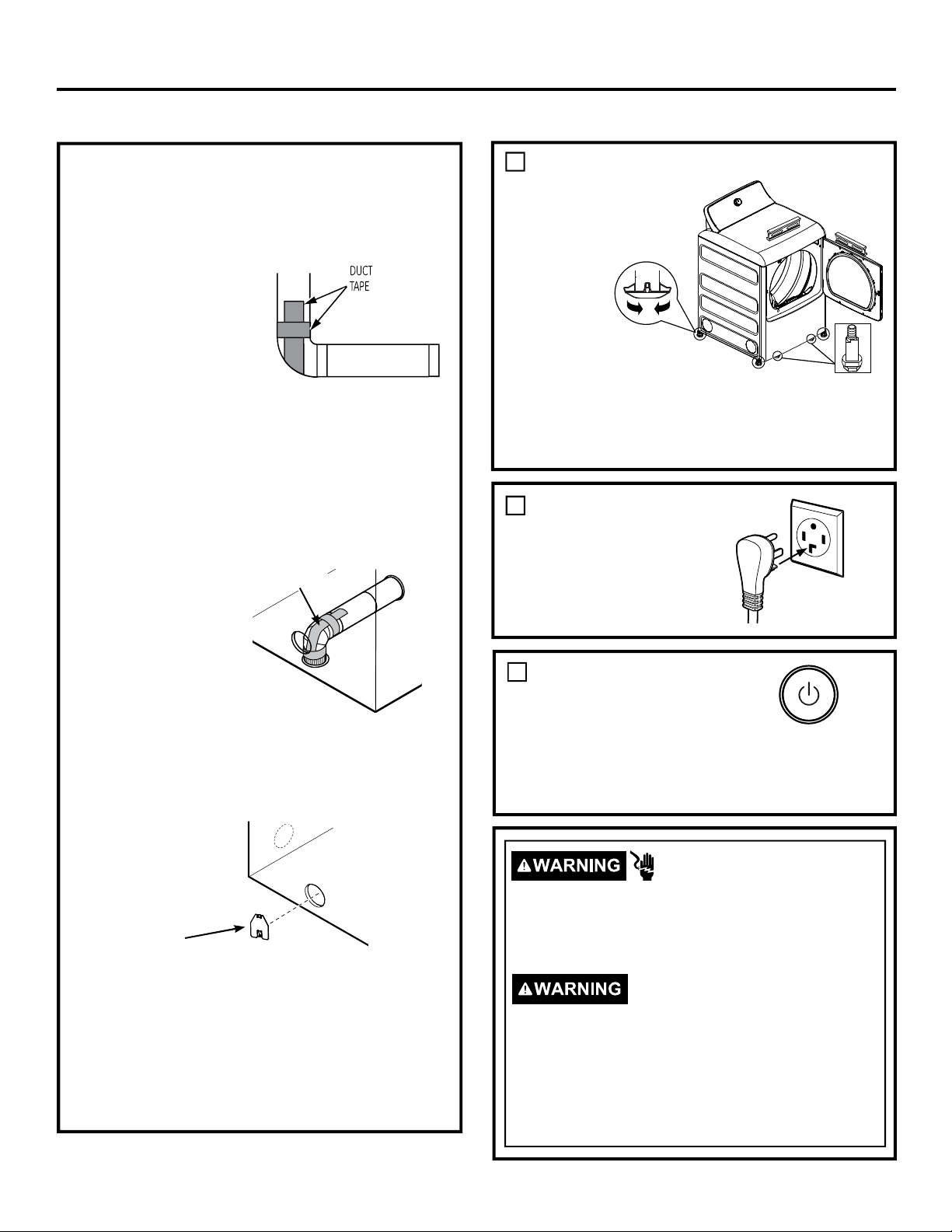
• Apply duct tape as shown
on the joint between the
dryer internal duct and
the elbow, and also the
joint between the elbow
and the side duct.
Use 4” rigid metal ducting
only inside the dryer. Internal duct joints must be
secured with tape, otherwise they may separate
and cause a safety hazard.
ADDING ELBOW FOR EXHAUST
THROUGH BOTTOM OF CABINET
• Insert the elbow through the rear opening and
connect it to the dryer internal duct.
• Apply duct tape as
shown on the joint
between the dryer
internal duct and the
elbow, and also the
joint between the elbow
and the bottom duct.
Internal duct joints
must be secured with tape; otherwise, they may
separate and cause a safety hazard.
ADDING COVER PLATE TO REAR OF
CABINET
Duct tape
FINAL SETUP
1
LEVEL THE DRYER
Stand the
dryer upright
near the final
location and
adjust the
leveling legs
at the corners
to ensure
the dryer is
level sideto-side and
front-to-back. Then, adjust the two anti-tip legs at the
front inner corners, taking care that they are touching
the floor to avoid unit tip over. The installation is not
complete until this process is finished.
2
PLUG DRYER IN
3
DRYER START-UP
Press the Power button.
NOTE: If the dryer has been
exposed to temperatures
below freezing for an extended period of time, allow it to
warm up before pressing Power. Otherwise, the display
will not come on. The dryer is now ready for use.
Raise
Lower
Ensure proper
ground exists
before use.
Anti-Tip Legs
(appearance will vary)
Plate
(Kit WE49X22606)
Connect standard metal elbows and ducts to complete
the exhaust system. Cover back opening with the plate
(Kit WE49X22606) which can be purchased from
GEApplianceparts.com or a local service provider.
Place dryer in final location.
NEVER LEAVE THE BACK OPENING WITHOUT
THE PLATE. (Kit WE49X22606)
- Electrical Shock Hazard
Disconnect power supply before servicing.
Replace all parts and panels before operating.
Failure to do so can result in death or electrical
shock.
- Shock Hazard
Certain internal parts are intentionally not grounded
and may present a risk of electric shock only during
servicing.
Service personnel – DO NOT contact the
following parts while the appliance is energized:
drum light, door switch, main electronic board,
igniter, thermostats, flame detector or mica heater.
16
Page 17
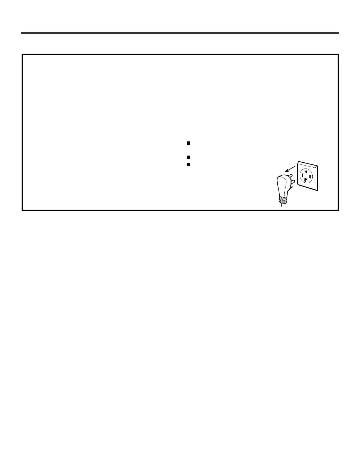
Installation Instructions
REVERSING THE DOOR (OPTIONAL)
ABOUT REVERSING THE DOOR
IMPORTANT NOTES:
• Read the instructions all the way through before
starting.
• Handle parts carefully to avoid scratching paint.
• Set screws down by their related parts to avoid
using them in the wrong places.
• Provide a non-scratch work surface for the door.
• Normal completion time to reverse the door
swing is 30–60 minutes.
IMPORTANT:
Once you begin, do not move the cabinet until door
swing reversal is completed. These instructions are
for changing the hinges from the right side to the left
side - if you ever want to switch them back to the right
side, follow these same instructions and reverse all
references to the left and right.
Tools needed:
Quadrex #1 bit screwdriver otherwise standard #2
Phillips screwdriver
Tape-tipped putty knife
Small flat blade screwdriver
Before you start
Unplug the dryer from its
electrical outlet.
17
Page 18
Installation Instructions
REVERSING THE DOOR (OPTIONAL)
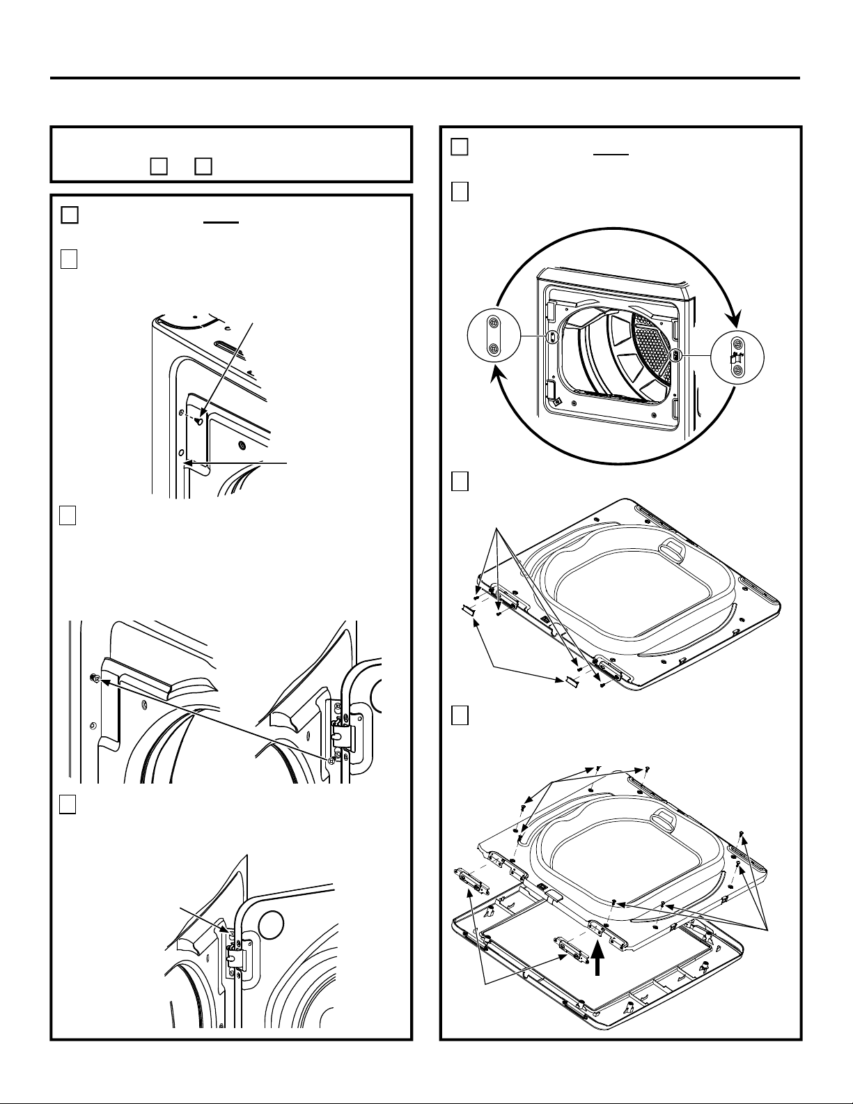
Choose the REVERSING THE DOOR
instructions A or B for your model.
A
MODELS WITHOUT FABRIC REFRESH
FEATURE
Open the door approximately 130°. With a putty
1
knife, remove the 4 plastic caps located along the
left side of the front panel and set them aside.
Plastic Cap (4)
Left side of
front panel
2
Remove the bottom screw from each hinge (right
side) and partially insert them into each top hinge
hole on the left side.
NOTE: All 4 front panel hinge screws will now be
in the top hinge holes - 2 on the left and 2 on the
right.
A
MODELS WITHOUT FABRIC REFRESH
FEATURE (cont.)
4
Remove both the blind plate and the strike plate and
install them in the opposite positions.
Blind
plate
Strike
plate
5
Remove the 2 hinge plastic caps and 4 hinge screws.
Hinge
screws
3
Loosen each top hinge screw on right side.
Remove the door and place it on a protective flat
surface to avoid any damage.
Loosen each
top hinge screw
on right side
18
Hinge
Plastic
Caps
6
Remove the 8 inside screws. Lift the inner door
upwards using a flat blade screwdriver. Remove the
2 door hinges.
Inside screws
Inner door
Door
Hinges
Outer door
Inside
screws
Page 19
Installation Instructions
REVERSING THE DOOR (OPTIONAL) (cont.)
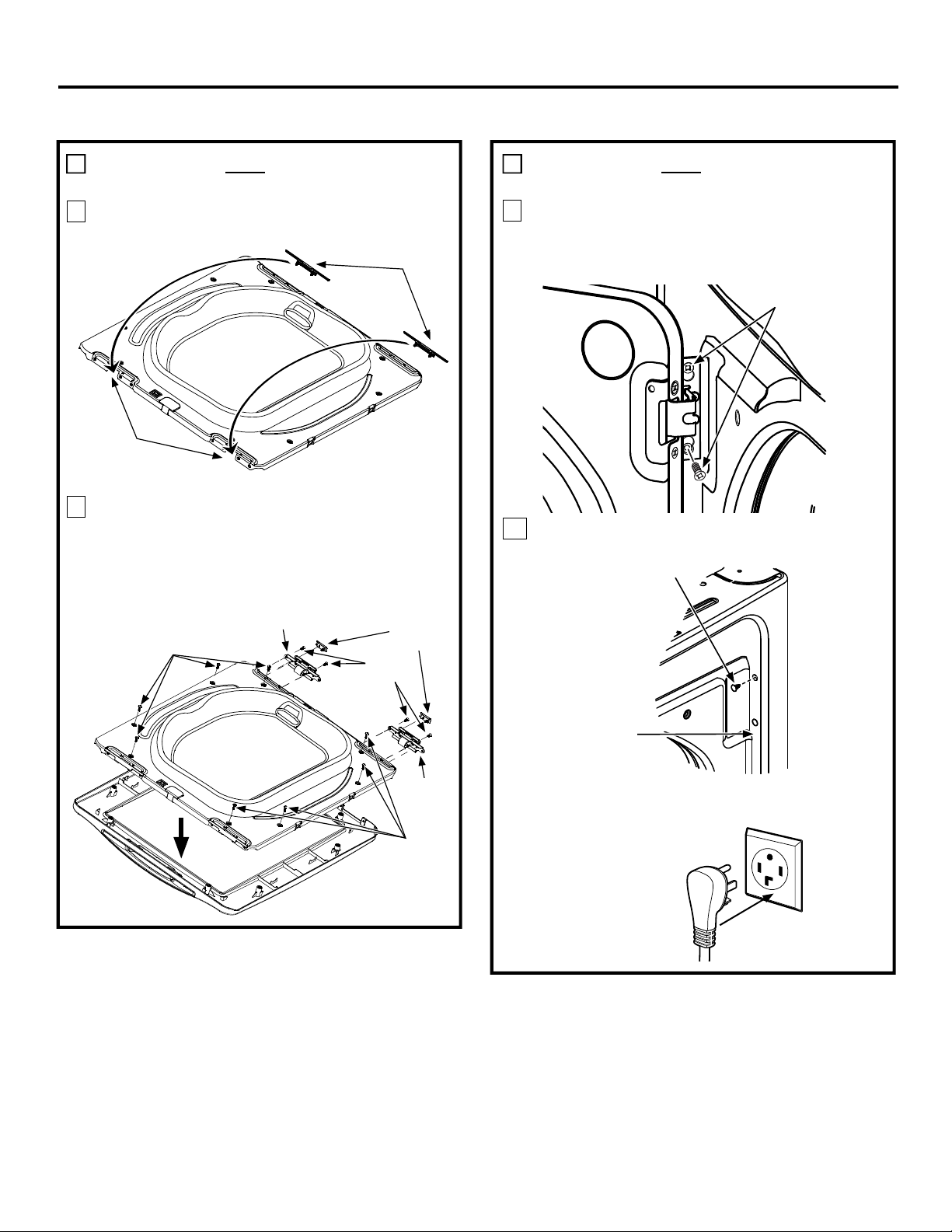
A
MODELS WITHOUT FABRIC REFRESH
FEATURE (cont.)
7
Remove and swap the two plastic caps onto the
opposite side.
Install plastic
caps from
opposite side
here
8
Rotate the outer door 180°. Place hinges into
position, making sure you mount the hinges on the
side opposite the pocket. Mount the inner door
back into the outer door frame and secure with
screws removed in step 6. Screw the door hinges
in and insert the hinge caps.
Inside
screws
Hinge
Hinge
screws
Plastic
Caps
Plastic
Caps
A
MODELS WITHOUT FABRIC REFRESH
FEATURE (cont.)
9
Mount the assembled door on the 2 upper left side
hinge screws installed in step 2. Move the hinge
screws loosened in step 2 into the lower left side
screw holes and firmly tighten all 4 screws.
Door
10
Install the 4 plastic caps removed in step 1 into
the 4 right side front panel holes.
Plastic Cap (4)
Hang door and
tighten screws
Inner door
Outer door
Hinge
Inside
screws
Right side of
front panel
NOTE: To return the door to the original setup, follow
these instructions, swapping “left” and “right”.
When you finish
Plug the dryer back into
its electrical outlet.
19
Page 20
Installation Instructions
REVERSING THE DOOR (OPTIONAL)
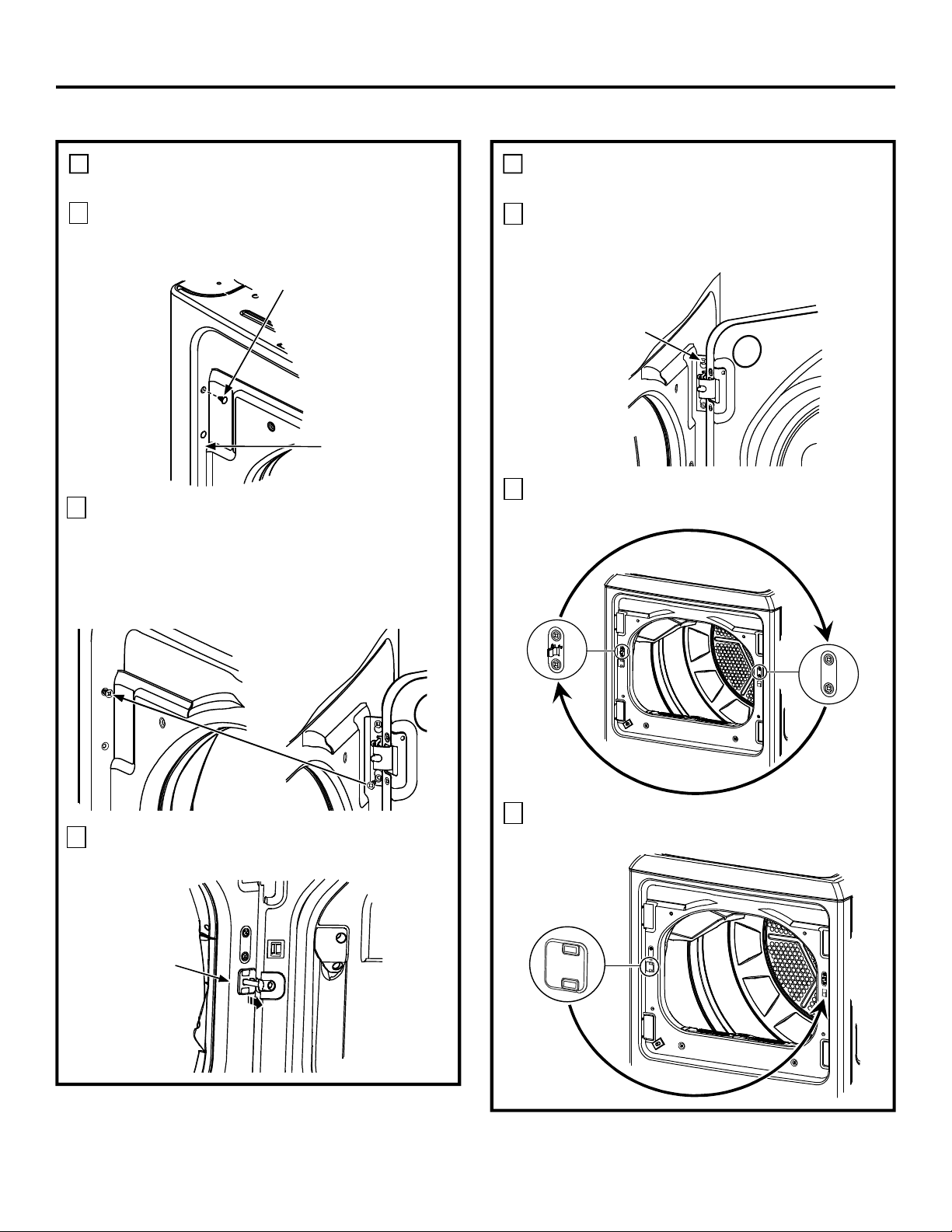
B
MODELS WITH FABRIC REFRESH
FEATURE
Open the door approximately 130°. With a putty
1
knife, remove the 4 plastic caps located along the
left side of the front panel and set them aside.
Plastic Cap (4)
Left side of
front panel
2
Remove the bottom screw from each hinge (right
side) and partially insert them into each top hinge
hole on the left side.
NOTE: All 4 front panel hinge screws will now be
in the top hinge holes - 2 on the left and 2 on the
right.
B
MODELS WITH FABRIC REFRESH
FEATURE (cont.)
4
Loosen each top hinge screw on right side.
Remove the door and place it on a protective flat
surface to avoid any damage.
Loosen each
top hinge screw
on right side
5
Remove both the blind plate and the strike plate and
install them in the opposite positions.
Strike
Plate
3
Use a small flat blade screwdriver to remove the
harness cover from the front panel.
Harness
Cover
6
Remove the plastic beauty cover and install it onto
the other side of the front panel.
Beauty
Cover
Blind
Plate
20
Page 21
Installation Instructions
REVERSING THE DOOR (OPTIONAL) (cont.)
B
MODELS WITH FABRIC REFRESH
FEATURE (cont.)
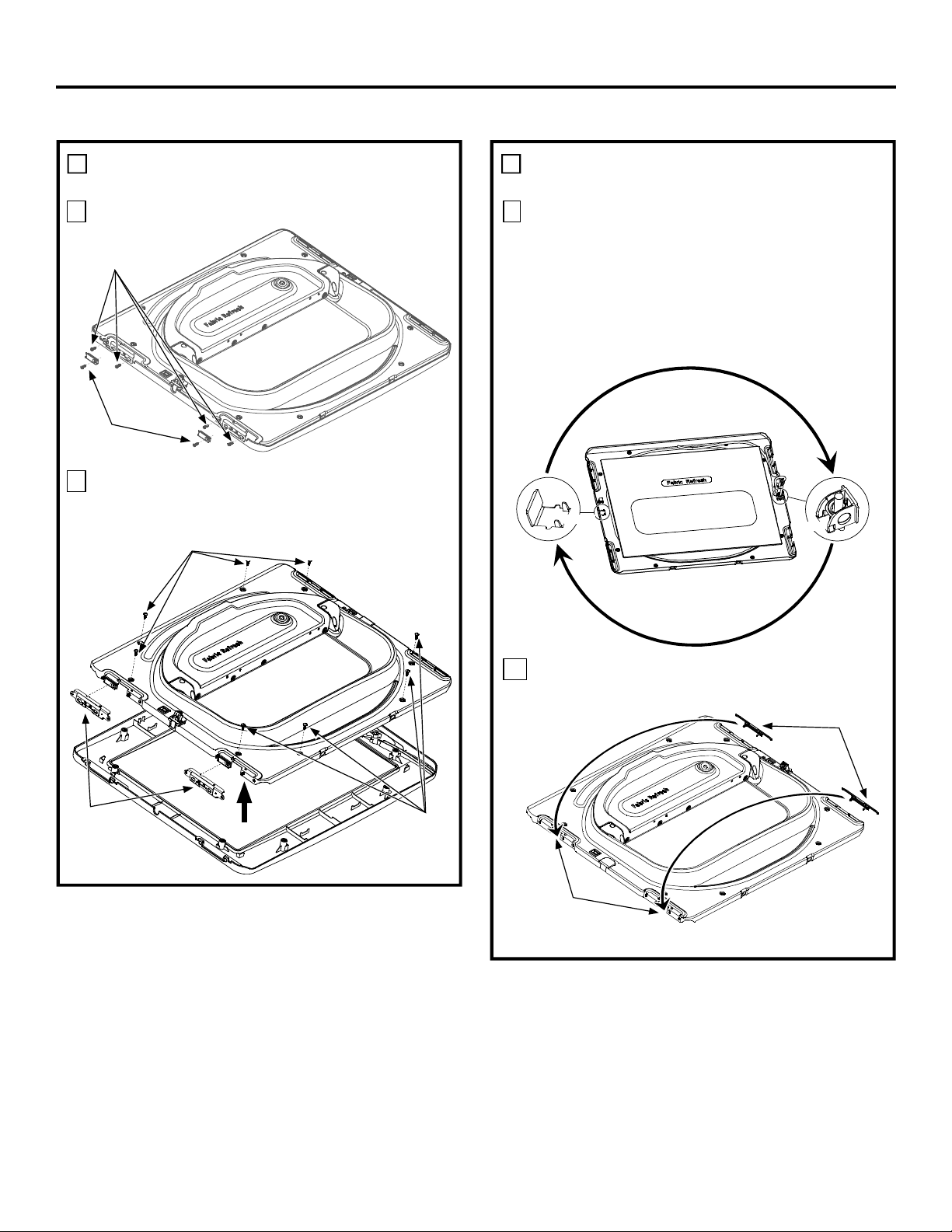
7
Remove the 2 hinge plastic caps and 4 hinge screws.
Hinge
screws
Hinge
Plastic
Caps
8
Remove the 8 inside screws. Lift the inner door
upwards using a flat blade screwdriver. Remove the
2 door hinges.
Inside screws
B
MODELS WITH FABRIC REFRESH
FEATURE (cont.)
9
Rotate the Inner door 180°.
Detach the harness retainer, by squeezing its clips
and pulling it out. Rotate it and swap it onto the
opposite side. IMPORTANT: Route its harness
behind the glass.
Remove the plastic cover, by squeezing its clips
and pulling it out. Rotate it and swap it onto the
opposite side.
Plastic
Cover
Clips
Inner door
Clips
Harness
Retainer
Door
Hinges
Outer door
Inner door
Inside
screws
10
Remove and swap the two plastic caps onto the
opposite side.
Install plastic
caps from
opposite side
here
Plastic
Caps
21
Page 22
Installation Instructions
REVERSING THE DOOR (OPTIONAL)
B
B
MODELS WITH FABRIC REFRESH
FEATURE (cont.)
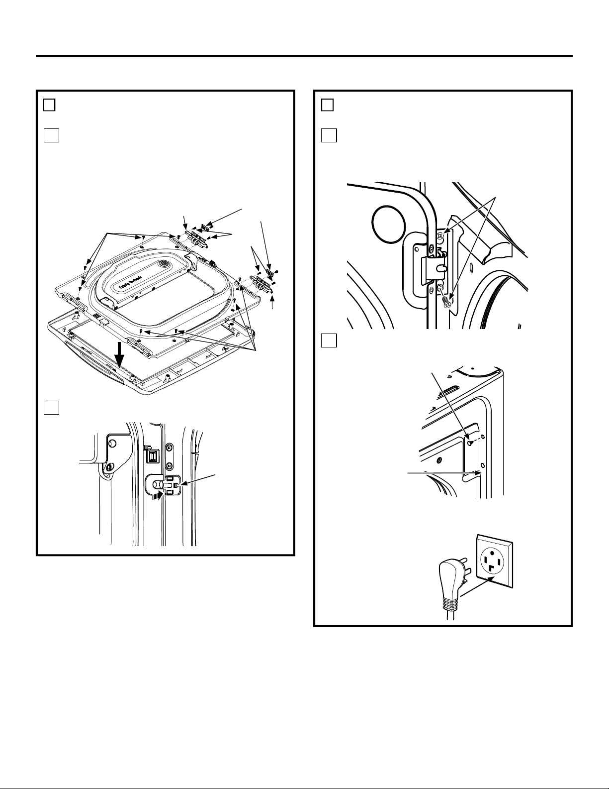
11
Rotate the outer door 180°. Place hinges into
position, making sure you mount the hinges on
the side opposite the pocket. Mount the inner
door back into the outer door frame and secure
with screws removed in step 8. Screw the door
hinges in and insert the hinge caps.
Inside
screws
Hinge
Inner door
Plastic
Caps
Hinge
screws
Hinge
MODELS WITH FABRIC REFRESH
FEATURE (cont.)
13
Mount the assembled door on the 2 upper left side
hinge screws installed in step 2. Move the hinge
screws loosened in step 2 into the lower left side
screw holes and firmly tighten all 4 screws.
Door
Hang door and
tighten screws
Outer door
12
Install the harness cover onto the front panel.
Harness
Cover
Inside
screws
14
Install the 4 plastic caps removed in step 1 into the
4 right side front panel holes.
Plastic Cap (4)
Right side of
front panel
NOTE: To return the door to the original setup, follow
these instructions, swapping “left” and “right”.
When you finish
Plug the dryer back into
its electrical outlet.
22
 Loading...