

Page 1
I
I
tall rio
tr ctio
Single Double Wall Oven
PT925
If gou have questions, call 1.800.GE.CARES or visit our website at: ge.com
Before You Begin
Read these instructions corefullg and completelg.
• IMPORTANT-savethese
instructions for local inspector's use.
• IMPORTANT-observea,
governing codes and ordinances.
• Note to Installer--Be sure to leave these
instructions with the consumer.
• Note to Consumer--Keep these
instructions for future reference.
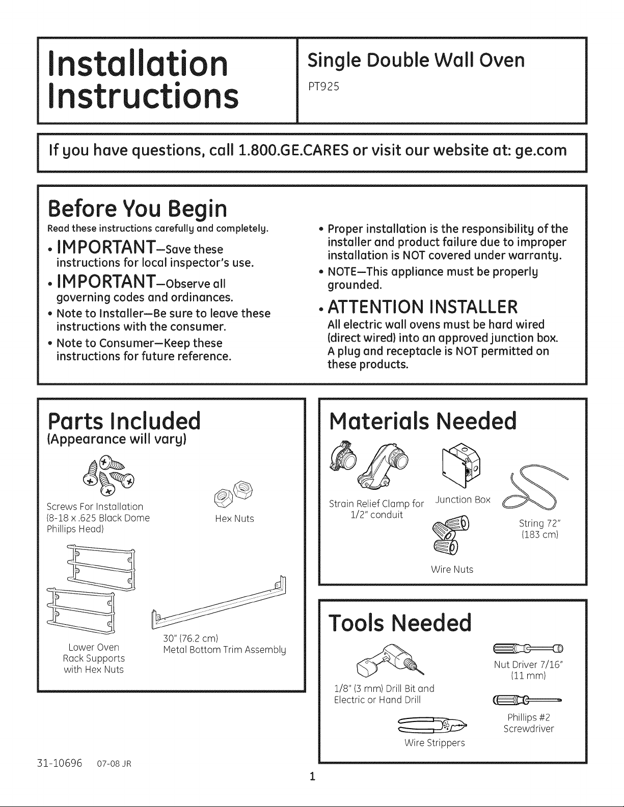
Ports Inclu ed
{Appearance will varg}
• Proper installation is the responsibilitg of the
installer and product failure due to improper
installation is NOT covered under warrantg.
• NOTE--This appliance must be properlg
grounded.
ATTENTION INSTALLER
All electric wall ovens must be hard wired
(direct wired)into an approved junction box.
A plug and receptacle is NOT permitted on
these products.
Materials
Needed
i
Screws For Installation
(8-18 x .625 Black Dome
Phillips Head)
Lower Oven
RackSupports
with HexNuts
31-10696 o7-o8JR
Hex Nuts
30" (76.2cm)
Metal Bottom Trim Assemblg
Strain Relief Clamp for
1/2" conduit
Junction Box
Wire Nuts
Tools Needed
1/8" (3mm) Drill Bit and
Electric or Hand Drill
Wire Strippers
String 72"
(183 cm)
Nut Driver 7/16"
(11 mm)
Phillips#2
Screwdriver
Page 2

InstallationInstructions
I PORTANT SAFETY INSTRUCTIO S
For Your Safety
. Be sure your oven is installed properly by
a qualified installer or service technician.
. Be sure the oven is securely installed in a
cabinet that is firmly attached to the house
structure. Weight on the oven door could
cause the oven to tip and result in injury.
Never allow anyone to climb, sit, stand or
hang on the oven door.
. Make sure the cabinets and wall
coverings around the oven can withstand
the temperatures (up to 200°F [93.3°C])
generated by the oven.
WARNING: The electrical
power to the oven supplg line must
being made. Failure to do so could
result in serious injurg or death.
Electrical Requirements
Thisappliance must be supplied with the proper
voltage and frequency, and connected to an
individual, properly grounded branch circuit,
protected by a circuit breaker or fuse. Seethe
rating plate located on the oven frame to determine
the rating of the product. Usethe chart below to
determine the minimum recommended dedicated
circuit protection.
Recommended
KW Rating KW Rating Circuit Size
240V 208V (Dedicated}
_<4.8KW _<4.1KW 20 Amp
4.9 KW-7.2 KW 4.3 KW-6.2 KW 30 Amp
7.3 KW-9.6 KW 6.3 KW-8.3 KW 40 Amp
9.7 KW-12.0 KW 8.4KW-IO.4 KW 50 Amp
ectrical Requirements
Rating plate is located on oven side trim, side
front frame or lower front frame.
Rating Plate Location
We recommend gou have the electrical wiring
and hookup of gour oven connected bg a
qualified electrician. After installation, have the
electrician show gou how to disconnect power
from the range.
Check with gour local utilities for electrical codes
which applg in gour area. Failure to wire gour
oven according to governing codes could result
in a hazardous condition. If there are no local
codes, gour oven must be wired and fused to
meet the requirements of the National Electrical
Code, NFPA No. 70-Latest Edition, available from
the National Fire Protection Association.
Effective Januarg 1, 1996, the National
Electrical Code requires that new, but not
existing, construction utilize a four-conductor
connection to an electric oven. When installing
an electric oven in new construction, a mobile
home, recreational vehicle or an area where
local codes prohibit grounding through the
neutral conductor, follow the instructions in the
section on NEW CONSTRUCTIONAND FOUR-
CONDUCTOR BRANCH CIRCUIT CONNECTION.
You must use a single-phase 120/208 VAC or
120/240 VAC, 60 hertz electrical sgstem. If gou
connect to aluminum wiring, properlg installed
connectors approved for use with aluminum
wiring must be used.
Page 3
InstallationInstructions
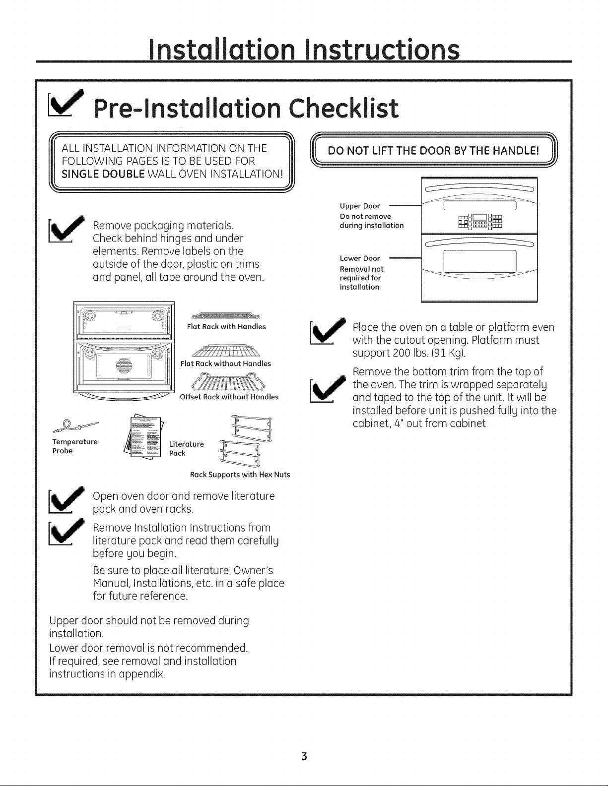
Pre-lnstallation Checklist
ALL INSTALLATIONINFORMATION ON THE
FOLLOWING PAGES ISTO BEUSED FOR Ill
SINGLE DOUBLE WALL OVEN INSTALLATION! III
Remove packaging materials.
Check behind hinges and under
elements. Remove labels on the
outside of the door, plastic on trims
and panel, all tape around the oven.
Upper Door
DO not remove
during installation
Lower Door
Removal not
required for
installation
IDDDD Drrrl
_D_DD_ D
Flat Rack with Handles
Fiat Rockwithout Handles
Offset Rack without Handles
Teom?eerature LpJtce_atu re
Rock Supportswith Hex Nuts
Openoven door and remove literature
packand oven racks.
Remove Installation Instructions from
literature pack and read them carefully
before you begin.
Besure to place all literature, Owner's
Manual, Installations, etc. in a safe place
for future reference.
Place the oven on a table or platform even
with the cutout opening. Platform must
support 200 Ibs. (91 Kg).
Remove the bottom trim from the top of
the oven. The trim is wrapped separately
and taped to the top of the unit. It will be
installed before unit is pushed fully into the
cabinet, 4" out from cabinet
Upper door should not be removed during
installation.
Lower door removal is not recommended.
If required, see removal and installation
instructions in appendix.
Page 4
Installationinstructions
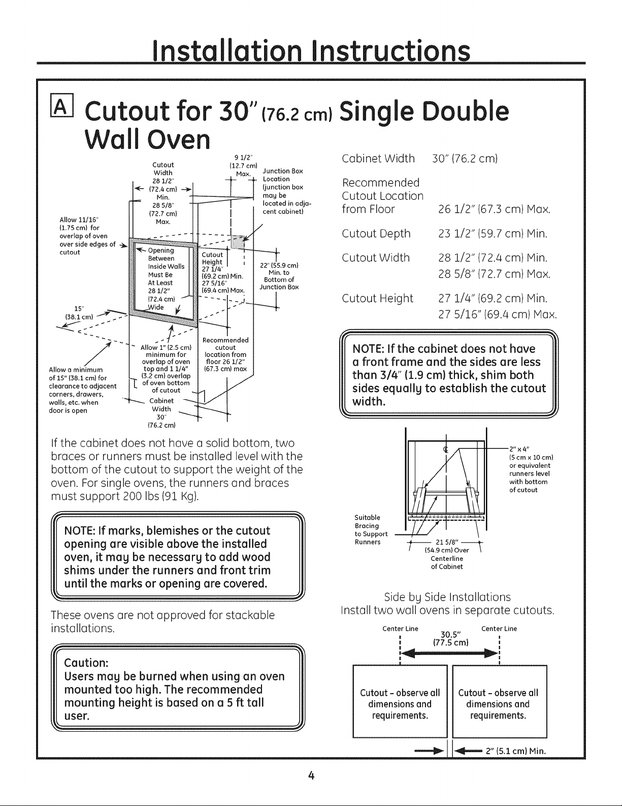
Cutoutfor 3
Wall Oven
Allow 11/16"
(1.75 cm) for
overlap of oven
over side edges of -_
cutout
Allow a minimum
of 15" (38.3. cm) for
clearance to adjacent
corners_ drawers_
walls, etc. when
door is open
$$
{76.2 cm)
Cutout 112.7 cm)
Width Max. Junction Box
28 112" Location
_-- (72.4 cm) --_ (junction box Recommended
Min. may be Cutout Location
28 5/8" located in adja-
(72.7 cm) cent cabinet) from Floor
Max.
g1/2- Cabinet Width
I
I
/
Single
Cutout Depth 23 1/2" (59.7 cm
_-- Opening
Between
inside Walls
Must Be
At Least
28 1/2"
(72.4 cm)
minimum for
overlap of oven
top and 1 1/4"
(3.2 cm) overlap
]_ of bottom
it
of cutout
.... Cabinet
Width
(76,2 cm}
(69.2 cm) Min.
27 5116"
{69.4 cm) Max.
Recommended
cutout
location from
floor26 1/2"
(67.3 cm)max
30"
----_ Cutout Width 28 1/2" (72.4 cm
22" {55.9 cm)
Min.to 28 5/8" (72.7 cm
Bottom of
Junction Box
-d
--4 Cutout Height 27 1/4" (69.2 cm
NOTE: If the cabinet does not have
ouble
30" (76.2 cm)
26 1/2" (67.3 cm
27 5/16" (69.4 cm) Max.
Max.
Min.
Min.
Max.
Min.
If the cabinet does not have a solid bottom, two
braces or runners must be installed level with the
bottom of the cutout to support the weight of the
oven. For single ovens, the runners and braces
must support 200 Ibs (91 Kg).
NOTE: If marks, blemishes or the cutout
opening are visible above the installed
oven, it may be necessary to add wood
shims under the runners and front trim
until the marks or opening are covered.
These ovens are not approved for stackable
installations.
Caution:
Users may be burned when using an oven
mounted too high. The recommended
mounting height is based on a 5 ft tall
user.
(5 cm x 10 cm)
or equivalent
runners level
with bottom
of cutout
Suitable
Bracing
to Support
Runners
i 21 5/8'' i
(54.9 cm) Over
Centerline
of Cabinet
Side by Side Installations
Install two wall ovens in separate cutouts.
Center Line Center Line
_ (77.5 cm) ',
W i
Cutout - observe all
dimensions and
requirements.
30.5"
Cutout - observe all
dimensions and
requirements.
2" (5.1 cm) Min
Page 5
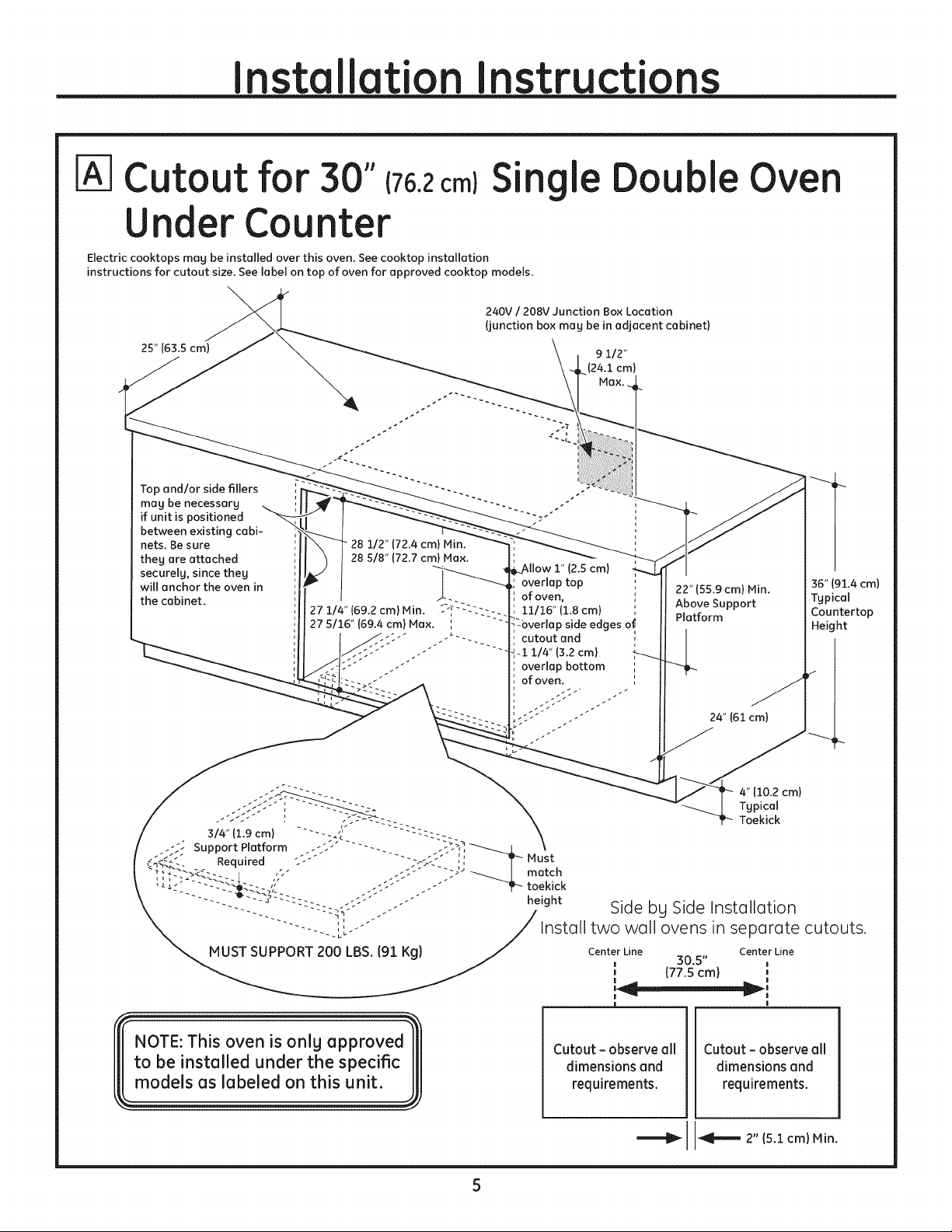
Cutoutfor 30" (76.2
ingle
UnderCounter
Electriccooktops mag be installedover thisoven. See cooktop installation
instructionsforcutout size.See labelon top of oven for approved cooktop models.
240V / 208V Junction Box Location
(junction box mag be in adjacent cabinet)
25" (63.5 cm)
Top andlor side fillers
mag be necessarg
if unit is positioned
between existing cabi-
nets. Be sure
they are attached
securely, since they
will anchor the oven in
the cabinet.
" 28 112" (72.4 cm) Min.
28 5/8" (72.7 cm) Max.
'overlap side edges of,
-i i14" (3.2 cm)
Double Oven
9 112"
(24.1 cm)
(2.5 cm)
overlap top
of oven,
11/16" (1.8cm)
cutout and
overlap bottom ',
ofoven. ',
22" (55.9 cm) Min.
Above Support
Platform
36" (91.4cm)
Tgpical
Countertop
Height
24" (61 cm)
4"(10.2cm)
Typical
Toekick
Side bg Side Installation
Install two wall ovens in separate cutouts.
Center Line Center Line
1 (77.5 cm} ',
! !
! !
| !
Cutout - observe all
dimensions and
requirements.
30.5"
Cutout- observeall
dimensions and
requirements.
2" (5.1 cm) Min.
Page 6
Cabinetr
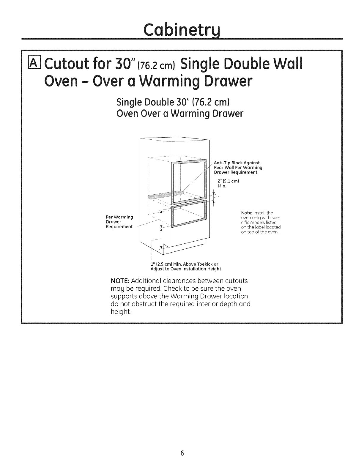
Cutoutfor 30"€76.2cm)SingleDouble
Oven- Overa Warming Drawer
SingleDouble30"176.2cm)
OvenOvera Warming Drawer
Anti-Tip Block Against
Rear Wall Per Warming
Drawer Requirement
2" (5.1 cm)
Min.
Per Warming
Drawer
Requirement
Note: Instoll the
oven onJg with spe-
cific models listed
on the label locoted
on top of the oven,
Wall
I" (2.5cm) Min. Above Toekick or
Adjust to Oven Installation Height
NOTE: Additional clearances between cutouts
mc]g be required. Check to be sure the oven
supports above the Warming Drc]wer location
do not obstruct the required interior depth and
height.
Page 7

Cabinetr
Cutout for 30"(76.2cm)Single DoubleWall Oven
Below an Advantium or Microwave Oven or
Between an Advantium or Microwave Oven
and a Warming Drawer
Single Double 30" (76.2 cm)
Oven Below an Advantium
or Microwave Oven
Per Advantium or
Microwave Oven
Requiremen t _
i.........
NOTE: The middle rail separating the two
openings may need to be larger than the 2"
(5.1 cm) minimum shown. Always refer to the
individual installation instructions packed with
each product for specific requirements.
Combined Advantium or Microwave
Ovenand Wall Oven Installation: When
installed in combination with a single wall oven,
use separate electrical junction boxes.
• Refer to the Advontium or microwave
oven installation instructions for electrical
requirements of that product.
• These connections must be made bu o
qualified electrician. All electrical connections
must meet National Electrical Code or
prevailing local codes.
2" (5.1 cm) 1Min.
Note: Install the
oven onlUwith spe-
cific models listed
on the label located
on top of the oven.
Single Double 30" 176.2cm)
Oven Between an Advantium
or Microwave Oven and a
Warming Drawer
Per Advantium or
1,4icrowave Oven
Requirement
Per Warming
Drawer
Requirement
NOTE: Additional clearances mag be required.
Check to be sure the oven supports above the
Warming Drawer do not obstruct the required
interior depth and height. The middle rail
separating the openings may need to be larger
than the 2" (5.1 cm) minimum shown. Always
refer to the individual installation instructions
packed with each product for specific
requirements.
Warming Drawer Combinedwith
Advantium or Microwave Ovenand
SingleOven:
Install a separate 120V, 60Hz, properl U
grounded receptacle. See installation
instructions packed with each product
for specific requirements.
2" (5.1cm) 1Min.
2" (5.1 cm) 1Min.
Page 8

Electrical Connections
ATTENTION INSTALLER
All electric wall ovens must be hard wired
(direct wired} into an approved junction box. A
plug end receptacle is NOT permitted on these
products.
DO NOT shorten the flexible conduit. The
conduit strain relief clamp must be securelg
attached to the junction box and the flexible
conduit must be securelg attached to the
clamp. If the flexible conduit will not fit within
the clamp, do not install the oven until a clamp
of the proper size is obtained.
NOTE TO ELECTRICIAN: The 3 power leads
supplied with this appliance are UL recognized
for connection to heavier gouge household
wiring. The insulation of these 3 leads is
rated at temperatures much higher than the
temperature rating of household wiring. The
current carrging capacitg of the conductor
is governed bg the wire gouge and the
temperature rating of the insulation around
the wire.
Turn off the circuit breoker or remove
fuses to the oven branch circuit.
With the oven supported on o toble or
platform in front of the cabinet opening,
connect the flexible conduit to the
electricol junction box as shown below.
Position the conduit in such (] monner that
it will lie in (] natural loop, in the conduit
pocket behind the unit, when the oven
is installed. You will need to purchase
an oppropriote stroin relief clamp to
complete the connection of the conduit to
the junction box.
Junction Box
Locotion
GROUND
Conduit
WARNING: improper
connection of aluminum house
wiring to copper leads con result
in an electrical hazard or fire.
Use onlg connectors designed
for joining copper to aluminum
and follow the manufacturer's
recommended procedure closelg.
Place oven on a
support to assist
inconnecting
conduit, must
support 2001bs
(91kg}.
"---------_L_(not included)
Stroin Relief Clamp
must be used at
Junction Box.
Page 9

New Construction and
Four-Conductor Branch
Circuit Connection
• When installing in new construction, or
• When installing in a mobile home, or
• When installing in a recreational vehicle, or
• When local codes do not permit grounding
through neutral:
a. Cut the neutral (white) lead from the crimp.
Re-strip the neutral (white) lead to expose the
proper length of conductor.
_ Junction Box
Cover
b. Attach the appliance grounding lead (green
or bare copper)in accordance with local
codes. Ifthe residence grounding conductor is
aluminum, seeWARNING on page 8.
c. Connect the oven neutral (white) lead to
the branch circuit neutral (white or grag) in
accordance with local codes, using a wire nut.
d. Connect the oven red lead to the branch
circuit red lead and the oven black lead to the
branch circuit black lead in accordance with
local codes, using wire nuts. If the residence
red, black or white leads are aluminum
conductors, see WARNING on page 8.
e. Install Junction Box Cover.
Three-Conductor Branch
Circuit Connection
When connecting to a three-conductor branch
circuit, if local codes permit:
a. Connect the bare oven ground conductor
with the crimped neutral (white)lead to
the branch circuit neutral (white or grag
in color), using a wire nut.
ound andJ_ Neutral Wires
Junction Box
Cover
b. Connect the oven red lead to the branch cir-
cuit red lead in accordance with local codes,
using a wire nut.
c. Connect the oven black lead to the branch
circuit black lead in accordance with local
codes, using a wire nut. If the residence
red, black or white leads are aluminum
conductors, see WARNING on page 8.
d. Install Junction Box Cover.
Page 10

Securing the Oven in the Opening
[_ Sliding the Oven Into the
Opening
o. Loopldo nettle} a 72" (183 cm) string around
the conduit before the oven is slid into place.
This will keep the conduit from falling behind
the oven.
"_: H: U
"_ _ f_ Q Q f' p m
b_
Lift oven into cabinet cutout using the oven
opening as a grip. Do not lift the door by the
handleJ Carefullg push against oven front
frame. Do not push against outside edges.
[_ Installing the Metal
Bottom Trim
a. Place the bottom metal trim under air
divider, with side flush against side trim.
Do this with the unit 4" out of the cabinet.
b. Using two trim screws provided, secure
the bottom trim to the bottom duct asm.
"_ Bottom Trim._
Trim Screw
Install bottom trim
with unit 4"
out of cabinet
C_
As gou slide the oven back, pull the string
so that the conduit will lie in a natural loop,
behind the oven.
d_
When gou are sure the conduit is out of the
wag, slide the oven 3/4 wag back into the
opening. Remove the string bg pulling on one
end of the loop.
IMPORTANT: If this unit is ever removed
from the cabinet or the oven is ever
pulled out for service, pull unit out 4" and
remove the bottom trim. This will prevent
damage to the trim.
10
Page 11

Drilling the Pilot Holes and
Mounting the Oven
r&]
Installing the Lower Oven
Rack Supports and Oven
Racks
sure the oven is pushed as far back into
the opening as it will go and centered.
a. Drill through the mounting holes of the side
trim, for the #8 screws provided.
............. zm_
Mounting Hole
S Locutions
(two provided)
Oven Rack Supports
Place the rack support with slotted holes over
the rear bolts and round holes over the front
bolts. Using a nut driver 7/16" (11 mm), lightly
secure with four nuts but do not overtighten or
the enamel could be chipped. Repeat for the
second rack support.
Slotted Round
holes over holes over
rear bolts front bolts
Oven Rocks:
Place the rear rack lock bar over and onto the
I_aW ""'"O:,ount,o0,c ew,
must be used. Failure to do so could [[[
result in the oven falling out of the [[I
cabinet causing serious injury. 111
rack supports, slide the rack all the way in until
the rear rack lock bar drops below the rack
supports. Pull rack forward and make sure the
rear rack lock bar is engaged under the rack
support.
b. Secure the oven to cabinet with screws
provided.
NOTE: If the cabinet is particle board, gou must
use #8 x 3/4" particle board screws. These meg
be purchased at ang hardware store.
11
Page 12

Pre-Test Checklist
Remove all protective film, if present,
and any stickers.
Check to be sure that all wiring is secure
and not pinched or in contact with
moving parts.
Operation Checklist
Remove all items from the inside
of the oven.
Check that conduit is securely
connected to the junction box.
Turn on the power to the oven. (Refer to
your Owner's Manual.) Verify that the
bake and broil units, and all cooking
functions operate properly.
Check that the circuit breaker is not
tripped nor the house fuse blown.
Seeyour Owner's Manual for
troubleshooting list.
Check that the bottom trim is installed
properly (see page 11).
Check to be sure the mounting screws
are installed and flush with the side trim
(see page 10).
NOTE TO ELECTRICIAN: The power
leads supplied with this appliance
are UL recognized for connections
to larger gauge household wiring.
The insulation of these leads is rated
at temperatures much higher than
the temperature rating of household
wiring. The current carrying capacity
of a conductor is governed by the wire
gauge and also the temperature rating
of the insulation around the wire.
NOTE: ALUMINUM WIRING
WARNING: IMPROPER
A.
CONNECTION OF ALUMINUM HOUSE
WIRING TO THE COPPER LEADS CAN
RESULT INAN ELECTRICAL HAZARD
OR FIRE.
B.
Splicecopper wiresto aluminum
wiringusing specialconnectors
designed and UL approved for
joiningcopper to aluminum,
and followthe manufacturer's
recommended connector
procedure closely.
12
NOTE: Wire used,locationand
enclosureofsplices,etc.,must
conform to good wiringpractice
and localcodes.
Page 13

Appendix
Lower Oven
Installation
oor emoval and
Instructions
DOOR REMOVAL
Bottom door removal is not recommended
for installation of the product.
E_ Open the oven door as far as it will go.
=_ ull both hinge locks
down toward the door
frame, to the unlocked
position. This mag
require a flat blade
screwdriver.
Hinge
Arm
DO NOT LIFTTHE DOOR BY THE HANDLE!
Place hands on both sides of
the door, and close the oven
door to the removal position,
which is most of the wag closed.
Lift door up and
out until the
hinge arms
clear the slots.
Hinge
Unlocked
Position
DOOR REPLACMENT
IT7 ift oven door bg placing
one hand on each side.
The door is heavy; gou
may need help. Do not
lift the door bg the handle.
=_ ith door at the same angle as removal
position, (most of the wag closed), seat the
notch of the hinge arm into the bottom
edge of the hinge slot. The notch of the
hinge arm must be fullg seated into the
bottom of the slot.
Hinge Arm
Bottom Edge
of Slot !
,/
Hinge Clears Slot
!-!
Hinge Notch
=_ Open the oven door as far as it will open.
[_ ush the hinge locks up against the front
[_ Close the oven door.
13
frame of the oven cavitg, to the locked
position.
Notch of Hinge
Securelg Fitted
into Bottom of
Hinge Slot
Hinge in Locked Position
Page 14

otes
14
Page 15

I
de
tr
®
I
O
CCIO
tal ci6
Horno de pared simple doble
PT925
#.Preguntas? Visite nuestro sitio en la Web: ge.com
Antes de empezar
Lea estas instrucdones cuidadoso g completamente.
• IM PORTANTE-Guorde estos
instrucciones g t_ngeles disponibles
pare el inspector local.
• IMPORTANTE-observetodos
los c6digos g ordenenzas vigentes.
• Note el insteledor-Cerci6rese de dejer
estes instrucciones can el propietario.
• Note el consumidor-Guerde estes
instrucciones pare userles coma
referencie en el futuro.
Partes incluidas
fie apariencio puede variar)
• La instalaci6n apropiada es responsabilidad
del instalador g la falla del producto par una
instalaci6nincorrectaNO est6cubiertapar la
garantia.
• NOTA--Este oparato debe estar conectado o
tierra adecuadamente.
iATENCION AL INSTALADOR!
Todos los hornos electr6nicos de pared deben
ser cobleodos directomente en uno cojo de
conexi6n oprobodo, Un "enchufe-recept6culo"
NO ESpermitido en estos productos.
Materiales necesarios
i
J
Tornillos para instalaci6n
(Cabeza de estrella tapa
negra de 8-18 x ;o25)
Soportes de la
bandeja del horno
inferior con tuercas
hexagonales
31-10696 07-08JR
Tuercas
hexagonales
30" (76,2cm)
Montaje de reborde
inferior de metal
Abrazadera de alivio conexi6n
caja de
de presi6n para
conducto de 1/2" _
Tuercas para alambres
Herramientas
necesarios
Una broca de 1/8" (3 mm) para
taladro el_ctrico o manual
Alicates pelacables
Cord6n de
72"(183 cm)
Llave de tuercas de
7/16" (iimm)
Destornillador de
estrella #2
Page 16

Instruccionesde instalaci6n
INSTRUCCIO
IMPORTANT
S
S
ESEGU IDAD
Para su seguri a
• Cerci6rese de que su horno sea instalado
adecuadamente por un instalador calificado
o por un t6cnico de servicio.
• Cerci6rese de que su horno est@firmemente
instalado en un gabinete que est@firmemente
adherido a la estructura de la casa. El peso sobre
la puerta del homo podria causar que el horno se
voltee resultando en lesiones. Nunca permita que
nadie se suba, se siente, se pare o se cuelgue de la
puerta del homo.
• Cerci6rese de que los gabinetes g los revestimientos
de la pared alrededor del horno puedan soportar
los temperaturas (hasta 200°F [93,3°C]) generadas
por el homo.
ADVERTENCIA:La energia
el@ctrica hacia la linea de suministro
del horno debe ser desconectada
mientras se hacen los conexiones.
No hacer esto podria resultar en
lesiones graves e incluso provocar
la muerte.
Requisitos el@ctricos
Esteaparato debe abastecerse con lafrecuencia
g el voltaje adecuados, gconectarse a un circuito el_ctrico
individual con conexi6n a tierra con protecci6n de un
fusible o interruptor autom6tico. Consulte la placa de
potencia ubicada en el marco del homo para determinar
la potencia del producto. Utilice el cuadro
a continuaci6n para determinar la protecci6n minima
recomendada para el circuito el@ctricoespecializodo.
Recomendable
Potencio KW Potencia KW Tama6o del circuito
240V 208V _ (Especializado)
_<4,8KW _<4,1KW 20 Amp
4,9 KW-7,2 KW 4,3 KW-6,2 KW 30 Amp
7,3 KW-9,6 KW 6,3 KW-8,3 KW 40 Amp
9,7 KW-12,0 KW 8,4 KW-IO,4 KW 50 Amp
Requisitos el ctricos
La placa de potencia se encuentra en la moldura lateral
del homo, el marco lateral frontal del homo o el marco
frontal inferior del homo.
Ubicaci6n de la ploco
de potencio
Recomendomos que elcobleodoy laconexi6nel6ctrico
de su horno los reolice un electricisto colificado. Despu6s
de la instalaci6n, solicite al electricista que le indique
c6mo desconectar la energia de la cocina.
Consulte con su compo_fo de servicios local
poro obtener los c6digos el6ctricos que seon oplicobles
en su 6reo. No hocer el cobleodo de su homo de monero
opropioda, respetando los c6digos vigentes, podrfa
resultor en condiciones peligrosos. Si no existen c6digos
locales, su aporato debe usor un cableodo gfusibles que
cumplon con los reguisitos del C6digo EI6ctrico Nocionol,
ANSIiNFPANo. 70-Ultimo edici6n. Usted puede obtener
uno copio de este c6digo disponible en Notional Fire
Protection Association (Asocioci6n Nocionol de Protecci6n
contro Incendios).
A portir del lro. de enero de 1996, el C6digo
EI6ctrico Nacionol requiere que todas los construcciones
nuevas, pero no existentes, usen una conexi6n de 4
conductores hocio cualquier homo el6ctrico. Cuondo
instole un homo el6ctrico en una construcci6n nuevo,
casam6vil,vehfculode recreaci6no un 6readonde los
c6digoslocolesprohibanlaconexi6na tierraotrav6sdel
conductor neutro, sigo los instrucciones en la Secci6n
CONSTRUCCIONESNUEVASYCONEXIONESDECIRCUITOS
RAMALESDE4 CONDUCTORES.
Usted debe usar un sistema el6ctrico de fase Onica
de 120/208 VAC o 120/240 VAC de 60 hercios.
Si hace una conexi6n a alambres de aluminio, debe
usar conectores adecuadamente instalados que est6n
aprobados para ser utilizados con cableados
de aluminio.
Page 17

Instruccionesde instalaci6n
Lista de controlantesde lainstalaci6n
Puerta superior_
Retire los materiales de embalaje. Revisedetr6s
de las bisagras g debajo del fondo falso. Retire
las etiquetas de lapuerta, el pl6stico de las
reborde g panel, todas las cintas alrededor del
homo.
No quitar durante
la instalaci6n
Puerta inferior
No se requiere
quitar para la
instalaci6n
IDDDD Drrrl
_D_DD_ D
Sonda de
temperatura
Bandeja piano con manijas
Bandeja piano sin manijas
I
Bandejodeslizable
sin manijas
instrucciones
Paquete de
Soportes de la bandeja con
tornilloshexagonales
Abra la puerta del horno y extraiga el paquete
de instrucciones y las parrillas del horno.
Extraiga las instrucciones de instalaci6n del
paquete g 16alascuidadosamente antes de
empezar la instalaci6n.
Cerci6rese de guardar bien todas las
instrucciones, Manual del propietario,
Instalaci6n, etc. para referencia en el futuro.
Coloque el horno sabre la mesa o plataforma
al nivel de la abertura del gabinete. La
plataforma debe soportar 200 Ibs. (91 Kg).
Extraiga el reborde demetal de la parte
superior del homo. La reborde de metal
est6 envuelta par separado g pegada a la
parte superior de la unidad. Se instalar6
antes de que la unidad se coloque par
completo dentro del gabinete, a 4" fuera
del gabinete.
La puerta superior no debe removerse durante
la instalaci6n.
No se recomienda desmontar la puerta inferior.
Sifuera necesario, consulte las instrucciones de
remoci6n e instalaci6n del ap@ndice.
Page 18

%
Carte para los hornos simple/dobles
de 30"(7o,z solamente
9 112"
Permita 11/16"
(1,75 cm) para
sobrepaso del
homo sabre los -_
bordes laterales .
del carte
Permita un minima
de 15" (38,3. cm)
de espacio para las
esquJnas, cajones,
paredes, etc., adga-
eentes cuando
Ja puerta est_ abierta
Ancho
_- deI corte --).
28 1/2"
_(72,4 cm) Min.
28 5/8"
(72,7 cm) M6×.
Abertura
entre los
paredes
intedores
debe estar
un minima
de 28 1/2"
(72,4cm)
el sobrepaso
del horno par
endma g 1 I/4"
(3,2 cm) par
I de 1" (2,5cm) para
debajo del carte
_ Ancho del
gabinete
30" (7E
(12,7cm)
I
I
(69,2 cm) Min.
27 5/16"
(69,4 cm) M6x.
Ubicaci6n
recomendada
para el corte
desde el piso
26 1/2"
(67,3 cm) M6x
-J
UbicacJ6n
de la caja
de conexi6n
(la caja
de conexi6n
puede estar
ubicada en
/un gabinete
adgacente)
22" (55,9 cm)
Min. hasta
la parte inferior
de la caja
de conexi6n
Siel gabinete no tiene un fondo s61ido, entonces
se deben instalar dos abrazaderas o correderas
nivelada con el fondo del carte para sostener el
peso del horno. Para hornos simple/dobles, las
correderas o abrazaderas deben soportar 200
Iibras (91 Kg).
NOTA: Si las marcas, imperfecciones
o la abertura del gabinete son visibles
par encima del homo instalado, quJz6s
sea necesario agregar relleno debajo
de las correderas g reborde delantera
hasta que se cubran.
Estos hornos no est6n aprobados para las
instalaciones apilables.
Ancho del
gabinete
30" (76,2 cm)
Ubicaci6n
recomendada
para el corte
desde el piso
26 1/2" (67,3 cm)
Profundidad
del corte
Ancho del corte
Altura de carte
NOTA: Si el gabinete no tJene un marco
Abrazaderas
de soporte
adecuadas para
las correderas
Instale dos hornos de pared en aberturas separadas.
_i 21 5/8" i
Instalaciones de lado a lado
Linea central Linea central
! !
' (77,5 cm)
23 1/2" (59,7 cm) Min.
28 1/2" (72,4 cm) Mfn.
28 5/8" (72,7 cm) M6x.
27 1/4" (69,2 cm) Mfn.
27 5/16" (69,4 cm) M6x.
(54,9 cm} Linea \
de eentro sobre
gabinetes
30.5"
t
x 4"
(5 cm x 10 cm)
o correderas
equivalentes
nivelada
con el fondo
del carte
Precauci6n:
Los usuarios pueden quemarse cuando
se usa un homo montado a una altura
mug elevada. La altura de montaje
recomendada se basa en un usuario con
una altura de 5 pies.
W i
Abertura - cum-
pla con todas los
dimensionesg
requerimientos.
Abertura - cum-
pla con todas los
dimensiones g
requerimientos.
_ 2" (5,1 cm) Min.
Page 19

%
Carte para los hornos simple/dobles
de 30" (70.2c_l- debajo de la superficle
del gabinete
Topes electricos de cocino se pueden instolor sabre este horno. Consulte los
instrucciones de la estufo paro el tomato del carte. Consulte la etiqueta encima
del homo pora los modelos de estufas aprobados.
25" (63,5 cm}
Material de reileno para
la porte superior g/o lados
padria ser necesario si
la unidod est6 ubicodo
entre gabinetes existentes.
Aseg0rese de que est_ pe-
godo firmemente ga que
_ste oncior6 el homo
en el gabinete.
28 112" (72,4 cm) Min.
28 518" (72,7 cm) M6x.
27 1/4" (69,2 cm) Min. _;_'-:LLLL,q
27 5/16" (69,4cm) M6x. ,
Ubicoci6n de la cajo de conexJ6n 240V / 208V
(lacoja de conexi6n puede estar ubicoda en
un gabinete adgacente)
9 112"
(24,1 cm)
_ermito 1" (2,5 cm)
poro el sobreposo
del horno par
encimo, 11/16"
-11,8 cm) poro el
"sobreposo de los
bordes Ioteroles
-del carte g 1 1/4"
13,2 cm) para
el sobreposo
del homo debojo
22" (55,9 cm) Min.
Par encimo de
la plataformo
soporte
24" (61cm)
_(>J
36" (91,4 cm)
Alturo tipico
del gobinete
NOTA: Este horno est6 aprobado
s61o para instalarse bajo los
modelos especificos indicados
en esta unidad.
Aberturo - cum-
ph con todas los
dimensiones g
requerimientos.
Abertura - cum-
pla con todos los
dimensionesg
requerimientos.
_ 2" (5,1 cm) Min.
Page 20

Gabinetes
Abertura para hornos simple/do es
e 30"€76,2cmlempotrados Sobre una
gaveta de calentamiento
Horno individual de 30" (76,2 cm}
sobre una gaveta de calentamiento
Bloque estable
contra la pared trasera
para la gaveta de
calentamiento requisitos
Basado en
requerimientos
de la gaveta
de calentamiento
1" (2,5 cm) Min. Por encima del z6calo
o ajustar a la altura de la instalaci6n
del horno
NOTA:Puede necesitarse una separaci6n
adicional entre las aberturas. Verifique
para asegurarse de que los apogos del
homo por encima de la ubicaci6n de
la gaveta de calentamiento no dificulten
la profundidad g altura interior requerida.
NOTA: Instale el
horno s61ocon los
modelos especificos
enumerados en
la etiqueta que se
ubica en la parte
superior del homo.
Page 21

Gabinetes
I_IAberturaparahornossimpleldoblesde30"€76,2cm_
DebajodeunAdvantiumodeunhorno
demicroondasoEntreunhornoAdvantium
ounhornodemicroondasyGavetadecalentmiento
Horno individual de 30" (76,2 cm)
debajo de un horno Advantium
o un horno de microondas
2" 15,icm) Min.
Nota: Instale el
homo s61o con los
modelos especificos
enumerados en
la etiqueta que se
ubica en la parte
superior del horno.
NOTA:Elcarril del media que separa lasdos aberturas
pueden necesitar ser m6s grande que el de2" (5,1cm)
minima que se muestra. Siempre consulte
las instrucciones para la instalaci6n que seremiten
con cada producto para obtener los requisitos especificos.
Instalaci6nparaelhornocombinado
Advantiumohornodemicroondasg
depared:
Para la instalaci6n en combinaci6n con un horno individual
de pared, utilice una caja de conexiones el_ctricas separada.
• Consulte lasinstrucciones de instalaci6n delhorno
Advantium o del homo de microondas para obtener
los requisitos de ese producto.
• Unelectricista autorizado debe realizar estas conexiones.
Todaslas conexiones el_ctricas debecumplir con las
normas del C6digoEl_ctrico Nacional
o los c6digos locales vigentes.
Horno individual de 30" (76,2
cm) Entre un horno Advantium
o un horno de microondas g
una gaveta de calentamiento
Basado en requerimientos
Advantium o horno
de microondas
Par gaveta de
calentamiento -_.....
requisitos
NOTA:Puedenecesitarse una separaci6n adicional entre
lasaberturas. Verifique para asegurarse de que los apogos
del homo por encima de la ubicaci6n de
la gaveta de calentamiento no dificulten la profundidad g
altura interior requerida. Elcarril del medio que separa las
dos aberturas pueden necesitar ser m6s grande que elde
2" (5,1cm)de m[nimo que semuestra. Siempreconsulte
lasinstrucciones para lainstalaci6n que seremiten con
cada producto para obtener los requisitos espec[ficos.
Gavetadecalentamientocombinada
conAdvantiumo hornodemicroondas
y hornoindividual:
Instale un recept6culo separado de 120V,60Hz,
adecuadamente con conexi6n atierra. Consulte
lasinstrucciones de instalaci6n remitidas con cada
producto para obtener losrequisitos espec[ficos.
2" 15,1cm) Min.
Page 22

Conexiones el ctricas
ATENCION AL INSTALADOR:
Todos los hornos el@ctricos de pared deben
ser cableados directamente en una caja de
conexi6n. Un "enchufe-recept6culo" NO ES
permitido en estos productos.
NO acorte el conducto flexible. La
abrazadera para controlar la presi6n debe
ester flrmemente adherida a la caja de
conexi6n y el conductor flexible debe ester
flrmemente adherido a la abrazadera. Si el
conducto flexible no se ajusta al interior de
la abrazadera, no instale el homo haste que
obtenga el tamaffo apropiado.
NOTA AL ELECTRICISTA: Los 3 alambres
el@ctricos proporcionados con este aparato
son reconoddos par la UL pare conexiones a
cableado residencial de mayor calibre.
El aislante de estos 3 alambres supera las
especificaciones de temperature indicadas
pare cableado residencial. La capacidad
actual de conducci6n del cable depende del
calibre del cableado g de la clasificaci6n de
la temperature del aislamiento alrededor del
alambre.
Desconecte el interruptor del circuito
o retire los fusibles que alimentan el
circuito ramal del horno.
Con el horno enfrente de la abertura del
gabinete, sabre una mesa o plataforma
conecte el conducto flexible a la caja
de conexi6n coma se muestra en la
figura. Coloque el conducto de manera
que quede apoyado sabre la parte
superior del horno en forma de bucle
natural cuando se instale el horno.
Usted necesitar6 comprar una
abrazadera Iiberadora de presi6n
para completar la conexi6n clel
conducto hacia la caja de conexi6n.
Ubicaci6n de la
caja de conexi6n
Conducto
Conexi6n atierra (
ADVERTENCIA: una
conexi6n inapropiada del cableado
de aluminio residential con cobre,
podria resultar en un peligro
ei@ctrico o haste en incendio. Use
solamente conectores diseffados
pare unir cobre con aluminio g siga
las recomendaciones del fabricante
con mucho cuidado.
Coloque el homo
en el soporte
pare eguder en
la conexi6n del
conductor, debe
soportar 200 fibres
(91kg).
Abrazadera liberadora
_resi6n (no incluida)
debe usarse en la caja
de conexi6n
Page 23

Conexi6n para nueva
construcci6n g de circuito
ramal de cuatro conductores
• Cuando se instale en una construcci6n nueva, o
• Cuando se instale en una casa m6vil, o
AI instalar en un vehiculo de recreacion, o
Cuando los c6digos locales no permitan hacer
conexi6n a tierra a trav6s de un cable neutro:
a. Corte la punta del alambre neutro (blanco)
del empalme. Pelela punta del alambre neutro
(blanco)hasta exponer la extensi6n apropiado del
conductor.
| Cone×i6n de circuito ramal
i - i
de tres conductores
Cuando conecte un circuito ramal de :3
conductores, si los c6digos locales Io permiten:
a. Conecte el alambre descubierto del horno
con el alambre neutro (blanco) del circuito
ramal (blanco o gris), usando una tuerca para
alambres.
_ Alambres de
conexi6n a tierra
de conexi6n
b. Conecte elalambre de conex6n a tierra (verde
o cobre descubierto)de acuerdo a los c6digos
locales.Siel conductor deconexi6n a tierra
dela residencia es de aluminio, consulte
la ADVERTENCIAen la p6gina 8.
c. Conecteelalambreneutrodelhorno(blanco)al
circuitoramalneutro(blancoogris)deacuerdo
conlosc6digoslocales,usandounatuercapara
alambres.
d. Conecte elalambre rojo del horno al alambre
rojo del circuito g el alambre negro del homo al
alambre negro del circuito de acuerdo con los
c6digos locales, usando las tuercas para alambres.
Silos alambres rojos,negros o blancos de la
residencia sonconductores de aluminio consulte
la ADVERTENCIAen la p6gina 8.
__mb[es de_ conexlon a tierra
Cubierta de la caja
de conexi6n
b_
Conecte el alambre rojo del horno al alambre
g neutro
rojo del circuito ramal, usando una tuerca
para alambres.
C_
Conecte el alambre negro del horno al
alambre negro del circuito ramal de acuerdo
a los c6digos locales, usando una tuerca
para alambre. Si los alambres rojos, negros
o blancos de la residencia son conductores
de aluminio, consulte la ADVERTENCIAen
la p6gina 8.
d. Instale la cubierta de la caja de conexi6n.
e. Instale la cubierta de la caja de conexion.
Page 24

© Posici6n firme dei horno en ia abertura
© C6mo deslizar el horno en el
interior de la abertura
a. Coloque (sin atar) una cuerda de 72"
(183 cm) alrededor del conductor antes de
deslizar el horno en su lugar. Esto evitar6
que el conducto se caiga detr6s del horno.
Tire hacia afuer_ _11II
por el lazo dela "711II
cuerd°mi?_t_s ..... n SllII
empuje el horno _ _ ..... i i IIII
.ocioe,in,__ ........ Ilollll
b_
Levante el horno hacia el interior del corte
en el gabinete usando la abertura del horno
para agarrarlo. Empuje contra el marco
frontal del horno cuidadosamente. No
empuje contra los bordes externos.
C_
A medida que el horno se desliza hacia atr6s,
tire de la cuerda para que el conducto quede
encima del homo de forma natural.
[-_ C6mo taladrar los orificios
piloto y montar el horno
o. Coloque el reborde de metal inferior debajo
del separador de aire, con el costado
alineado con el reborde lateral. Haga esto
con la unidad a 4" (10 cm)fuera del gabinete.
b. Utilizando los dos tornillos de reborde
provistos, fije el reborde inferior al montaje
del conducto inferior.
Reborde inferior 7
Instale el reborde inferior
con Io unidod 4" (10 cm)
fuera del c abinete
Q
Tornillo del reborde
d_
Cuando est@seguro de que el conducto est6
fuera del camino, deslice el homo :3/4 del
tragecto hacia atr6s g hacia el interior de
la abertura. Retire la cuerda halando de
un extremo.
_"[10cm)_--
10
Page 25

[_ C6mo taladrar los orificios
piloto y montar el horno
NOTA: Antes de perforar los orificios
piloto, cerci6rese de que el homo se
empuj6 hasta el fondo y de que est_
centrado.
a. Perfore a trav_s de los orificios de montaje de
la moldura lateral, para los tornillos #8 que se
proporcionan.
Ubicoci6n de
los orificios
C -O
de montaje (dos
provistos)
| C6mo instalar los soportes de
la bandeja y las bandejas del
homo del homo inferior
Soportes de las bandejas del
horno
Coloque el soporte de la bandeja con los
orifidos ranurados sobre los pernos traseros y
los orifidos redondos sobre los pernos frontales.
Utilizando una Ilave de tuercas de 7/16" (11
mm), ajuste suavemente con cuatro tuercas,
pero no ajuste de m6s porque el esmalte podria
saltarse. Repita para el segundo soporte de la
bandeja.
\
ADVERTENCIA:
Ill _ se deben usar tornillos de montaje. Iil
Ill No hacerlo podria resultar en que III
III el horno se caiga del gabinete, III
L
b. Ajuste bien el horno al gabinete con los
tornillos que se proporcionan.
NOTA: Si el gabinete es de tabla aglomerada
debe usar tornillos #8 x 3/4". Los puede adquirir
en cualquier ferreteria.
Orificios ranura-
dos sobre pernos
traseros
Orificios redondos
sobre pernos frontales
Bandejas del horno:
Coloque la barra de bloqueo de la bandeja
trasera sobre los soportes de la bandeja,
deslice la bandeja hacia adentro hasta que la
barra de bloqueo de la bandeja trasera caiga
debajo de los soportes de la bandeja. Tire la de
bandeja hacia adelante y verifique que la barra
de bloqueo de la bandeja trasera est@ sujeta
debajo del soporte de la bandeja.
11
Page 26

Lista de control antes de la prueba
Retire cualquier cinta de protecci6n y eti-
queta que todavia est6 presente.
Revise pare asegurarse de que todos
los alambres est6n bien conectados y
no aplastados o en contacto con partes
m6viles.
Inspeccione la moldura de fondo para
cerciorarse de que est6 instalada
apropiadamente (ver p6gina 11).
Inspeccione para cerciorarse de que los
tornillos de montura est6n instalados g
apretados hasta quedar al mismo nivel
de la moldura lateral (ver p6gina 10).
Lista de control para la operaci6n
Retire cualquier articulo del interior
del homo.
Cerci6rese de que el conducto est6
conectado firmemente ala caja de
conexi6n el6ctrica.
Conecte la energia hacia el horno. (Consulte
su Manual del propietario.) Verifique que
las unidades de horneado g asado, g
todas las funciones de cocci6n operan
correctamente.
Cerci6rese de que el interrupter de circuito
no se haga disparado o de que los fusibles
de la case no est6n quemados.
Consulte el manual del propietario para una
Iista de problemas eventuales.
NOTA AL ELECTRICISTA: Los olambres
el_ctricos proporcionodos con este
operate son reconocidos per Io UL pore
conexiones cobleodo residential de mogor
calibre. El oislonte de estos olombres
supero los especificociones indicodas
pare cobleodo residenciel. Lo copocidod
actual de conducci6n del cable depende
de Io ciosificoci6n de Io temperature del
oislemiento olrededor del olembre.
NOTA: CABLEADO DE ALUIINIO
ADVERTENCIA:
A_
UNA CONE×I6N INAPROPIADA
DEL CABLEADO DEL ALUIINIO
RESIDENCIAL CON EL COBRE, PODRIA
RESULTAREN PROBLEIAS SERIOS0 EN
INCENDIO.
B_ Conecte los olombres de cobre o
los alambres de aluminio usando
conectores especiales dise_ados
g oprobodos per UL pore unir cobre
g oluminio g sigo cuidodosomente
ei procedimiento pare hater los
conexiones recomendodos per
ei fobriconte.
12
NOTA: El alambrado que se use,
Io ubicaci6n g el tipo de conexi6n,
etc., deben cumplir con los buenos
pr6cticas de alambrado g los c6digos
locales.
Page 27

A ndice
Instrucciones de instalaci6n g
de la puerta del horno inferior
J
de remocion
C6MO QUITAR LA PUERTA
No se recomienda quitar la puerto inferior
parala instalaci6n del producto.
E_ Abra la puerta del homo en su totalidad.
_ resione ambas trabas de la bisagra hacia
C
abajo en direcci6n del marco de la puerta
hasta destrabarlas. Para esto Posici6n
destornillador _, bisagra
depuedehacer falta unlades _' _,_ dela
p,anos, dela V_._,fi_
iNO LEVANTE LA PUERTA DE LA MANIJA! _/]
Coloque las manes en ambos "[_-_
lades de la puerta g cierre la
puerta del homo hasta la posici6n
de remoci6n, que es casi cerrada.
Levante la puerta fl_k_ ' ',:,'/,'....
hasta que los brazes j Jll\\_ ....
dela bisagra hagan ilU, --_1,_ ;; .,','
salido de las ranuras.
Ranura
bisagra _
destrabada
Braze de la
bisagra
i /
3J
C6MOREEMPLAZAR LA PUERTA
Levante la puerta del
horno colocando una
mane en cada lade.
La puerta es pesada g
quiz6s necesite aguda.
No levante la puerta
per laempuBadura.
Con la puerta en el mismo 6ngulo que la
posici6n para remoci6n, que est6 cerrado
la magor parte del tiempo, coloque la mu-
esca del braze de la bisagra en el interior
del borde inferior de la ranura de la bisa-
gra. La muesca del braze de la bisagra
debe apogarse completamente al fondo
de la ranura.
Borde inferior
dela ranura \
\
Braze de Io bisagra
,X
/-
La bisagra sale de la ranura
Muesca de la bisagra
T_ Abra la puerta del horno hasta el m6ximo.
_ mpuje los topes de las bisagras contra
[_1 Cierre la puerta del horno.
13
el marco frontal de la cavidad del homo,
hasta alcanzar la posici6n de cierre.
Bisagra en la posici6n de cierre
Huesccl de lo
bisagra ajustoda
firmemente en
el rondo de le
ranura de _b
la bisagra
Page 28

otas
14
 Loading...