

GE PSS27SGNABS, PSS25SSNASS, PSS25SGNABS, PSH23SGNABS, PSC23SSNASS Owner’s Manual
GEApp/iances.com
Safety Instructions ........... 2-4
°e,,,_
U3
Operating Instructions
Additional Features ............ ] 2
Automatic Icemaker ........... 14
Care and Cleaning .......... 16, 17
Crispers and Pans ............. 13
CustomCool T'_. ............... 7, 8
Ice and VVater Dispenser . .... 15, 16
Refiigeramr Doors ............ 12
Replacing the Light Bulbs ....... 18
Shelves and Bins ........... 10, 11
Temperature Controls ........... 5
TurboCool r'* . .................. 6
_4'ater Filter ................... 9
Installation Instructions
Preparing to Install
the Refiigerator ............ 24, 25
Removing and Replacing Doors . .23
Trim Kits and Panels ........ 19-22
Water Ifine Installation ...... 26-30
Troubleshooting Tips ....... 32-34
Normal Operating Sounds ...... 31
Models23,25,27 and29
Profile C6te fi C6te
R frig6rateurs
La section frangaise commence h la page 42
Profile Lado a Lado
Refrigeradores
La seccion en espa_ol empieza en la pagina 78
Consumer Support
Consumer Support ..... Back Cover
Performance Data Sheet ........ 37
Product Registration ........ 39, 40
State of Calitbrnia ¼'ater
Treamaent Device Certificate ..... 38
_'arranty (Canadian) ........... 35
_4'arranty (U.S.) ............... 36
Write the model and serial numbers here:
Model #
Serial #
Find these numbers on a label inside
the reti'igerator compartment at the
top on the right side.
200D2600P016 49-_018_ 11-01Jfl
IMPORTANTSAFETYINFORMATION.
READALLINSTRUCTIONSBEFOREUSING.
A WARNING!
Use this appliance only for its intended purpose as described in this Owner's Manual
SAFETYPRECAUTIONS
When using electrical appliances, basic safety precautions should be followed, including the following:
_,':;This reli-igerator must be properly installed
and located in accordance with the Installation
h_structions beiore it is used.
_,':;Do not allow children to climb, st;rod or hang
on the shelves in the refl'igerato_: They could
damage the refligerator and seriously iqim'e
themselves.
:)::Do not touch the cold surli_ces in the fl'eezer
compartment when hands are damp or wet. Skin
may stick to these extremely cold sm_thces,
i,;:Do not store or use gasoline or other flammable
\:q_ms and liquids in the vicini F oI this or any
other appliance.
i,_:_In refiigerato_s with atltOll/atic icemake_s,
avoid contact with the moving parts of the
ejector mechanism, or with the heating element
locamd on the bottom of the icemake_: Do not
place finge_ or hands on the aUtOlnatic
icemaking mechanism while the refl_igerator
is plugged in.
i/:;Keep finge_s out _ff the "pinch point" areas;
clearances between the dom_ and between
the (loo_ and cabinet are necessarily small.
Be careful closing doms when children are
in the area.
i/:;Unplug the refl'igerator befin'e cleaning and
making repairs.
NOTE."We stronglyrecommendthatany servicingbe
performedby a quafifiedindividual
i,_:_Setting either or both controls to 0 (off)does not
remove power to the light circuit.
::NDo not refl'eeze fl'ozen foods which have
thawed complemly.
@Alwa_:s clean the CustomCooY_Tray after thawing
tOod.
2

DANGER!RISKOFCHILDENTRAPMENT
PROPERDISPOSALOFTHEREFRIGERATOR
GEAppliances.com
Child entrai)ment and suffocation are not i)rol)lems
of the past, Junked or abandoned refl_igeratm_ are
still dangerous...even if they will sit fin" "just a fi_w
days." If you are getting rid of yore" old refrigeratm;
please follow tile instructions below to hel I) prevent
accidents.
Before YouThrowAway YourOldRefrigerator
or Freezer:
i;_?Take off tile dome.
CFCDisposal
Ymr old refl_igerator may have a cooling system
that used CFCs (chlorofluorocarbons). CFCs are
believed to ham_ stratospheric ozone.
If you are throwing away yore" old refrigerator; make
sm'e tile CFC refl_igerant is removed fin" proper
disposal by a qualified se_wice_: If you intentionally
release this CFC reflJgerant you can be subject to
fines and imprisomnent under provisions of
enviromn ental legislation.
>_ I,eave tile shelves in place so that children max
not easilx climb inside.
USEOFEXTENSIONCORDS
Because of potential safety hazards under certain conditions, we strongly recommend against the use
of an extension cord.
However, ifxou must use an extension cord, it is absolutelx necessary that it be a UITlisted (in tile United
States) or a (;SA-listed (in (_anada), 3-wire grom_ding type appliance extension cord haxim,_ a ,gr°m_ding
type I)hw_ and outlet and that tile electrical rating, of tile cord be 15 amperes (minimum) and 120 xolts.
IMPORTANTSAFETYINFORMATION.
READALLINSTRUCTIONSBEFOREUSING.
A WARNING!
HOWTOCONNECTELECTRICITY
Do not, under any circumstances, cut or remove the third (ground) prong from the power cord. For
personal safety this appliance must be properly grounded.
The power cord of this appliance is equipped
with a 3-prong (grounding) plug which mates
with a standard 3-prong (grounding) wall outlet
to minimize the possibili V of electric shock hazard
fl'om this appliance,
Have the wall outlet and circuit checked by a
qualified electfidan to make sure the outlet is
properly grounded.
If the outlet is a standard 9-prong outlet, it is your
personal responsibili_, and obligation to have it
replaced with a propedy grounded 3-prong wall
outlet,
The refl-igerator should always be plugged into its
own indixidual electrical outlet which has a xoltage
rating that matches the rating plate.
This provides the best perfln_nance and also
I)rexents oxerloading, house wiring circuits which
could cause a fire hazard fl'om oxerheated wires.
Never unI )lu,*_,xour refl'igerator, bx, i)tilling, on the
power cord. _Mwa)_, II,gfi ) )lug firefly, and pull ,straioht
out fl'om the outlet.
Repair or replace immediately all power cords that
have become fl'aved or otherwise damaged. Do not
use a cord that shows cracks or abrasion damage
along its length or at either end.
\_]_en moving the reflige_mn" away fl'om the
wall, be careflfl not to roll over or damage the
power cord.
USEOFADAPTERPLUGS(Ad_pte_plug_notpe_mittedinc_d_)
Because of potential safety hazards under certain conditions, we strongly recommend against
the use of an adapter plug.
Howe\'et; if'you, must use an adaptet; where local
codes pemfit, a temporary connection may be made
to a l)roperly grounded 2-prong wall outlet by use
of a UI Aisted adapter a\:lilable at most local
hai'dware stoi'es,
The linger slot in the adapter must be aligned with
the larger slot in the wall outlet to provide proper
polari b' in the connection of the power cord.
When disconnecting the power cord fl'om the
a(lapte_; always hold the adapter in place with one
hand while pulling the power cord I)lug with the
other hand. If this is not done, the adapter ground
temfinal is very likely to break with repeated use.
If the adapter ground temfinal brea!cs, DO NOT
USEthe refrigerator until a proper ground has
been established.
Attaching the adapter ground terminal to a waft outlet
cover screw does not ground the appliance un/ess the
cover screw is meta/, and not ihsu/ated, and the waft
outlet is grounded through the house wiring. Youshou/d
have the circuit checkedby a qualified e/ectriclan to make
sure theoutlet is propedy grounde_
READANDFOLLOWTHISSAFETYINFORMATIONCAREFULLY.
SAVETHESEINSTRUCTIONS
4
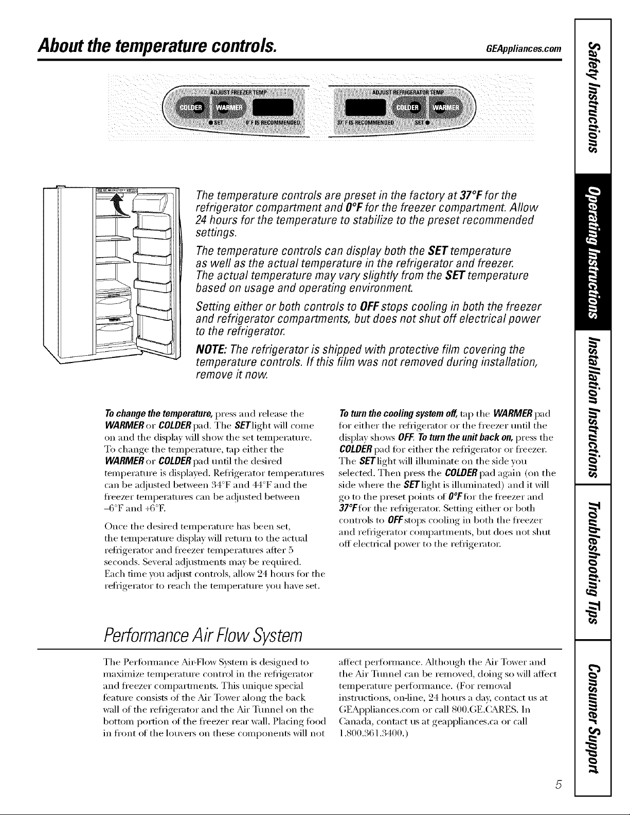
Aboutthe temperaturecontrols. GEAppliances.com
The temperature controls are preset in the factory at 37°1:for the
refrigerator compartment and O°Ffor the freezer compartment. Allow
24 hours for the temperature to stabilize to the preset recommended
settings.
The temperature controls can display both the SET temperature
as well as the actual temperature in the refrigerator and freezer.
The actual temperature may vary slightly from the SET temperature
based on usage and operating environment.
Setting either or both controls to OFFstops cooling in both the freezer
and refrigerator compartments, but does not shut off electrical power
to the refrigerator.
NOTE: The refrigerator is shipped with protective film covering the
temperature controls. If this film was not removed during installation,
remove it now.
Tochange the temperature, press and release the
WARMER or COLDERpad. Tile SETlight will come
on and tile display will show tile set temperature.
To change tile temperature, tap either tile
WARMER or COLDERpad tlntil tile desired
temperature is displayed. Refl_igerator temperatm'es
can be at!lusted between 34°F and 44°F and tile
fl'eezer temperatm'es can be a(!justed between
-6°F and +6°E
Once tile desired temperature has been set,
tile temperature display will return to tile actual
refl-igerator and fl'eezer temperatm'es after 5
seconds. Several ac!iusnnents may be required.
Each tilne you ac!itlSt controls, allow 24 hotli'S tk)r tile
refl-igerator to reach tile temperatm'e you have set.
PerformanceAir FlowSystem
Toturn the cooling system off,tap tile WARMER pad
tot either the reti_igerator or the fl'eezer until the
display shows OFF.To turn the unit back on, press the
COLDERpad fin" either the refl_igerator or fl'eezer.
The SETlight will illuminate on the side wm
selected. Then press the COLDERpad again (on the
side where the SETlight is illuminated) and it will
go to tile preset points of O°FfOr tile fl'eezer and
37°FtOr tile refl-iger:mn: Setting either or both
controls to OFFstops cooling in both the fl'eezer
and refrigerator compartments, but does not shut
off electrical power to tile refl_igerato_:
Tile Perl0mmnce M_=Flow System is designed to
maximize temperature control in tile refrigerator
and fl'eezer comlxmments. This unique special
featm'e consists of tile Mr Tower along tile back
wall of tile refrigerator and tile Mr Tmmel on tile
bottom portion _fftile fl'eezer rear wall. Placing food
in fl'ont of tile lou\'e_ on these components will not
affect pe_fommnce. Mthough tile Mr Tower and
the Mr Tmmel can be removed, doing so will affect
temperatm'e i)e_fomlance. (For remox_d
instructions, onqine, 24 horns a da> contact us at
GEAl)pliances.com or call 800.GE.( ;ARES. In
Canada, contact us at geappliances.ca or call
1.800.361.3400.)
About TurboCoolY
ffl.
TurboCool
How it Works
TurboCoolrapidly cools the retiigerator
compartment in order to more quickly
cool fl)ods. Use TurboCoolwhen adding a
large amount of tood to the refligerator
compartment, putting away fi)ods alter they
have been sitting out at i'OOill temperature
or when putting away warm leliovei_. It can
also be used if the refrigerator has been
without power tot an extended period.
Once acti\:_ted, the compressor will turn oil
immediateh' and the tiros will cycle on and
off at high speed as needed for eight houis.
The compressor will continue to run until
the refligerator compartment cools m
approximately 34°F (l °C), then it will cvcle
on and off to maintain this setting. _Mter 8
hom_, or if TurboCoolis pressed again, the
refrigerator compartment will return to
the original setting.
How to Use
Press TurboCooLThe refl_igerator
temperature display will show TC.
_Mter TurboCool is complete, the
reflJgerator compartment will return
to the miginal setting.
NOTES:The reliigerator temperature
cannot be changed during
TurboCoot
The fl'eezer temperatm'e is not
affected during TurboCooL
When opening the refligerator
door dining TurboCool,the liras
will continue to run if they have
cycled on.

AboutCustomCooU GEAppliances.com
TurboCool • SET ExpressThaw ExpressChill Se/ectTemp
How it Works
Tile CustomCool _ teature is a system oI
dampe_, a tim, a temperature themfistor
and a heate_; Depending on tile fimction
selected, a combination ot these will be
used to quickly chill items, thaw items or
hold tile pan at a specific teinperature.
How to Use
Tile pan is tightly sealed to prevent tile pan's
temperature fl'om catLsing temperature
fltlCttlafions in tile rest ot tile reflJgerato_:
Tile controls fin" this pan are located at tile
top of the reiiigerator with the temperatm'e
controls.
ExpressThawTM
ExpressChillTM
Empty tile pan. Place tile (:hill/Thaw
t)
trm in tile pan with tile metal plate
timing down to chill and store items, or
with the metal })]ate thong up to thaw
items. Place the items on the tray and
close the pan completely.
elect the ExpressThaw,ExpressChd/
@
or Se/eetTemp _ pad, The displa_ and
SETlight will come on. Tap the pad
mltil the light appem_ next to the
desired setting. Use the chart to
detemfine the best setting to use.
i_i;: To stop a featm'e befin'e it is
finished, tap that teatm'e's pad
tmtil no options are selected and
the display is off.
N DtwJng ExpressThaw_ and
rM " rM
ExpressChilE_the displa) on the
controls will count down the time
in tile cycle.
_i:: _Mier tile ExpressThaw_ cycle is
complete, tile pan will reset to tile
MEATsetting (31°F) to help presex_'e
thawed items tmtil they are used.
i_i;:Tile displayed actual temperature (ff
the CustomCoolpan may \m'y slightly
ti'om the SETtemperamre based on
usage and operating environment.
NOTE: For food safety reasons, it is
recommended that foods be wrapped
in plastic wrap when using ExpressThawY
This will help contain meat juices and
improve thawing perlimnance.
7

AboutCustomCoo/:
CustomCooF _ Chart
NOTE:Resultsmay vary depending onpackaging, starting temperature and other food traits.
.....
Exp,essThaw SoiectTemp
0.5 Lb. (4 hours)
>: Hamburger Patties (0.5 lb)
>: ]ndMdually _Vrapped
Filet Mignon (0.5 lb)
1.0 Lb. (6 hours)
i_? Chicken Breasts (1.0 lb)
i_: Ground Beef (1.0 lb)
i_;: Steak (1.0 lb)
2.0 Lbs. (10 hours)
i_: Chicken Breasts (2.0 lbs)
i_;: (h'otmd Beef (2.0 lbs)
>: Steak (2.0 lbs)
3.0 Lbs. (12 hours)
i_i: Chicken Breasts (3.0 lbs)
i_;: (h'otmd Beef (3.0 lbs)
>: Steak (3.0 lbs)
15 Minutes
>: 1 Beverage Can (12 oz)
_i:: 2 Slnall,luice Boxes (('_ oz each)
30 Minutes
i_;: 2 to 6 Beverage Cans (l 2 oz each)
i_i: 2 Plastic 20 oz Bottles of Beverage
i_i;:4 to 6 Small Juice Boxes
(C_8 oz each)
yi:: 3 Foil Juice Packets
_i:: Wine (750 ml bottle)
45 Minutes
_i:: 2 I,iter of Beverage
i_i;:1/2 Galhm of.Juice
>: Gelatin-1 package
About the CustomCoolTM Pan Rack and Tray
Citrus Setting (43°F)
>: Oranges, I,emons, IJmes,
Pineapple, (_antaloupe
>: Beans, (]tlCtllllbei_, Tomatoes,
Peppe_, Eggplant, Squash
Produce Setting (35°F)
i_;: Strawberries, I?.aspberfies, Kiwifl'tfit,
Pea_s, Cherries, Blackberries,
Glwpes, Phuns, NectmJnes, Apples
>: Asparagus, Broccoli, Corn,
Mushrooms, Spinach, Caulifl()we_;
I_ade, Green Onion, Beets, Onions
Meat Setting (31 °F)
Raxs Meat, Fish and Poultry
Disassemblingthe
Chill/Thaw tray
8
Toclean the Chill/Thaw tray,disassemble the
metal tray fl'om the plastic stand by lightly
>
pushing in on the handles of the plastic
stand and removing the metal tray. Both
the metal tray and the plastic stand are
dishwasher safe.
Toreassemble the tray, place the plastic
stand upside d(>wn (handles (m bott(>m) (m
a solid sm'ti_ce. Place the metal plate on top
ol the stand matching up the curved side of
the plate with the curved side of the stand.
Insert one side of the plate into the notches
on the stand. Push in on the handle on the
other side (ff the stand while pushing that
end of the plate down and into place. You
should hear the plate "click" into place.
About the water filter. (onsomemodels) CEAppliances.com
/
Cartri_
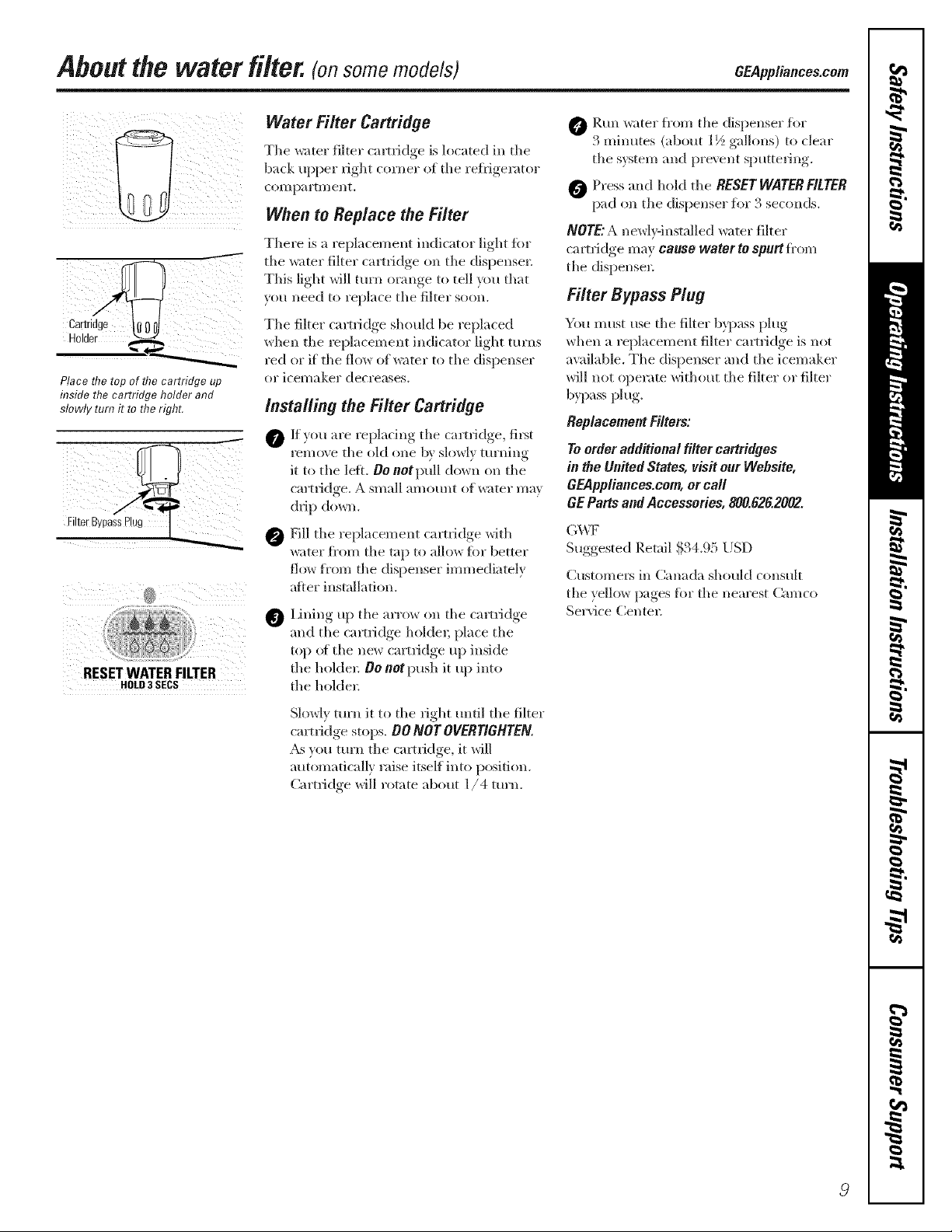
Place flTetop of flTecartridge up
inside the cartridge holder and
slowly turn it to the right.
i 2'_!5_=_! !!i?_¸'¸¸
RESETWATERFILTER
HOLD3 SECS
Water Filter Cartridge
Yhe water filter (am'idge is hwa/ed in the
back Iq)per fight corner of the reflJgerator
coi//p31"[///ellt.
When to Replace the Filter
Yhere is a replacement indicator light fin.
the _ter filter cartridge on the dispense_;
Yhis light will turn orange to tell you that
you need to replace the filter soon.
Yhe filter cartridge should be replaced
when the leplacemem indicator light turns
red or if the flow of water to the dispenser
or icelnaker decreases.
Installing the Filter Cartridge
O If you, are repl'mim,, ,, the c'u'tridoe_, fil_t
remove the old one bx slowE mrnino
it to the left. 0e notpull down on the
cartridge. A small amotmt of water ma}
drip down.
_Fill the teplacement cartridge with
water fi'om the tap to allow for better
flow fi'om the dispenser immediately
aDer installation,
Lining up the arrow on the cartridge
@
and the cam-idge holder; place the
top of the new cartridge up inside
the hokle_: OO not push it up into
the hokle_:
O P.un water fl'om the dispenser fiw
3 minutes (about 1½ gallons) to dear
the system and pro\ ent sputtering.
O Press and hold the RESET WATER FITTER
pad on the dispenser fi)r 3 seconds.
NOTE: A newl}qnstalled water flter
cartridge may cause water to spurt fi'om
the dispense_:
Filter Bypass Plug
You must use the filter b}])ass plug
when a replacement filter cartridge is not
ax:dlable. The dispenser and the icemaker
will not ol)erate without the filter or filter
bypass plug.
ReplacementFilters:
To order additional filter cartridges
in the United States, visit our Webs#e,
GEAppliances.com,or call
GE Parts and Accessories, 800.626.2002.
G_v\TF
Suggested Retail $34.95 USD
Customers in Canada should consult
the ? ello_ pages fin" the nearest Camco
Service Centel:
Slowly turn it to the right m/til the filter
cam-idge stops. O0 NOT OVERTIGHTEN.
,_s you turn the cartridge, it will
automatically raise itself into position.
Cartridge will rotate about 1/4 turn.
Abouttheshelvesandbins.
Not all features are on all models.
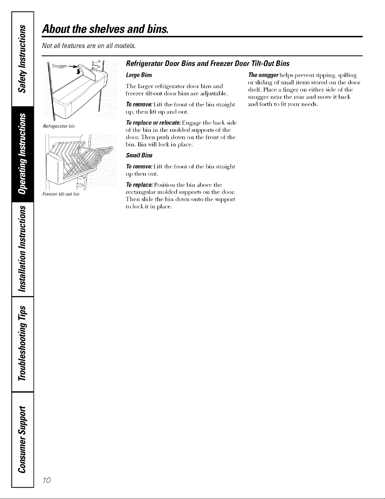
Refrigerator Door Bins and Freezer Door Tilt-Out Bins
LargeBins
The larger refi_igerator do(n" bins and
freezer tilt-out door bins are ac!justable.
Toremove: lift the front of the bin straight
up, then lift up and out.
Thesnuggerhelps prevent tipping, spilling
or sliding of small items stored on the door
shelf, Place a finger on either side of the
snugger near the rear and move it back
and torth to fit vom" needs.
Refrigerator bin
Freezer tilt-out bin
To replace er relecate: Engage the back side
of the bin in the molded sui)ports of the
dora: Then push down on the ti'ont of the
bin. Bin will lock in place.
Small Bins
To remove: Lift the fl'ont of the bin straight
up then out.
To replace: Position the bin above the
rectangular molded supports on the (loox:
Then slide the bin down onto the support
to lock it in place,
/0
Not aft features are on all models.
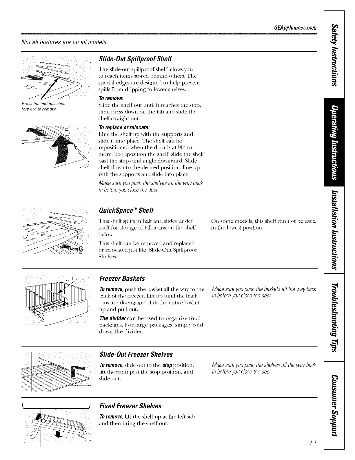
Slide-Out Spillproof Shelf
il/ i
Presstabandpull shelf
forwardtoremove
The slide-out spillproof shelf allm_s y,')u
to reach items stored behind othe_. The
special edges are designed to hel I) pre',ent
spills fl'om dripping to lower shelves.
Toremove:
Slide the shelf out until it reaches the stop,
then press down on the tab and slide the
shelf straight out.
Toreplace or relocate:
I,ine the shelf uI) with the SUl)ports and
slide it into place. The shelf can be
reposifioned when the door is at 90 ° or
more. To reposition the shelf; slide the shelf
past the stops and angle downward. Slide
shelf down to the desired position, line up
with the supports and slide into place.
Make sure you push the shelves all the way back
in before you dose the door
GEPppliancesocom
OuickSpace TM Shelf
This shelf splits in half and slides under
itself fbr storage ot tall items on the shelf
below.
This shelf can be removed att(1 replaced
or ielocatedjust like Slide-Out Spillproof
Shel_vs.
Freezer Baskets
Toremove, push the basket all the way to the
back of the ti'eezet: i,ift up until the back
pins are disengaged. I,ifl the entire basket
up and pull ()tit.
The divider can be used to organize ti)od
packages. For large packages, simply fold
down the divider.
(¸¸¸¸¸¸!¸¸7¸¸¸¸¸¸¸¸¸/¸¸¸¸¸¸¸¸¸(
Slide-Out Freezer Shelves
Toremove, slide out to the stop position,
lift the ti'ont past the stop position, and
slide out.
On some models, this sheff can not be used
in the lowest position.
Makesureyoupushthebasketsall thewayback
in beforeyouclosethe door
Makesureyoupushtheshelvesaft the wayback
in beforeyouclosethe door
Fixed Freezer Shelves
Toremove, lift the shelf up at the left side
and then bring the shelf out.
//

Abouttheadditional features.
Not all features are on all models.
Removable Beverage Rack
t
The beverage rack is designed to hold
a bottle on its side. It can be attached to
any slide-out shelfi
Abouttherefrigeratordoors.
Refrigerator Doors
The refl-igerator (loo_ may teel (liflerent
than tile ones you are used to. Tile special
door opening/closing teatm'e makes sm'e
the (loo_ close all the way and are secm'elv
sealed.
To install'.
0 Ihle up tile large part ot the slots on
the top of the rack with the tabs trader
the shelf,
Then slkle the rack back to lock it
in place,
Tile resistance _ou teel at tile stop
I)osition will be reduced as the door
is loaded with food.
When opening and closing tile door you
will notice a stop position. If tile door is
opened past this stoppoint, tile door will
remain open to allow w>u to load and
mlload fi)od more easily. When tile door
is only partially open, it will automatically
close.
When the door is only partially open,
it will automatically close.
Beyond tiffs stop flTedoor will stay open.
Door Alignment
...._=====l_ nd,,,,,__.e.ne.en,_,¢,,sttheie._ge,_,t,.
Jll ] d,>o,:
[['_'{((_ / _ Using a 7/16" socket wreilch, turn the
LLIII[I ' _ door a(!justing screw to tile right to
_ [ / raise tile do(>,; t(> tile left to h>wer it.
I!l [ (A nyhm ph,g, imbedded in tile
Ill / th,e_,dsofthepin,p,e.entsthepin
<_ from ttlrning tinless a wrench is t/sed.)
"W k 1_716"Socke_Wrenchl
Tore,,_ovethe,,ase_-I...._, I
grille,openthedoors, I I-t@_1 I
removethescrewat I_,__£'_1 I I
eachendofthe base I --r---'--,,_,_ j
grilleandthenpull ¢2___'_.......I
the0ri,es_raight_ut.[ _=-_......I
O AJ'teI" one oi" two tt/rns of tile wI'ench,
oI)en.... and close the refrigerator, door
and check the aligmnent at the top of
tile doors.
12
Aboutthe crispersandpans. CEAppliances.com
Not all features are on all models.
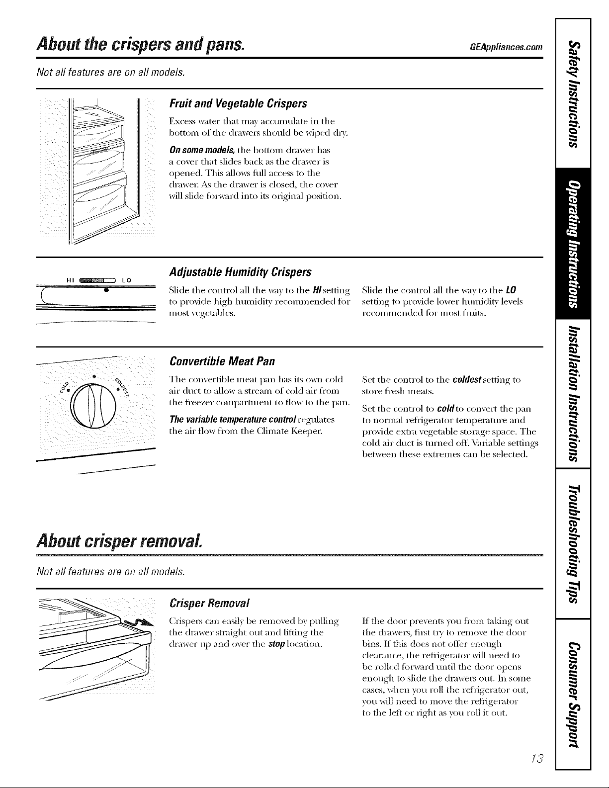
Fruit and Vegetable Crispers
Excess water that may accmnulate in the
bottom of the (h'awet_ should be wiped (h_':
On some models, the botton/drawer has
a covet" that slides back as the drawer is
opened. This allo_:s fitll access to the
drawer: _s the drawer is closed, the cover
will slide fin'ward into its original position.
Hi _ LO
Adjustable Humidity Crispers
Slide the control all the way to the HIsetting
to provide high humidi_' recommended fin.
most vegetables.
Convertible Meat Pan
The convertible meat pan has its own cold
air duct to allow a stream of cold air fl'om
the fl'eezer compartment to flow to the pan.
The variable temperature control regulates
the air flow ti'om the Climate Keel)et:
Aboutcrisperremoval.
Slide the control all the way to the LO
settino_ to proxide lower humidi_' lexels
recommended fi)r most fl'uits.
Set the control to the coldest setting to
store fl'esh meats.
Set the control to coldto convert the pan
to nomml refiigerator temperature and
provide extra vegetable storage space. The
cold air duct is turned ofli ¼mable settings
between these extremes can be selected.
Not all features are on all models.
Crisper Removal
Crispers can easily be remo\vd by pulling
the drawer straight out and lifting the
drawer up and over the stop location.
If the door prevents }_m fl'om taldng out
the (hawers, fil_t tt)' to remove the door
bins. If this does not offer enough
clearance, the reflJgerator will need to
be rolled fi)rward until the door opens
enough to slide the drawers out, In some
cases, when you roll the reflJgerator ottt,
you will need to move the refi'igerator
to the leit or fight as you roll it out,
/3
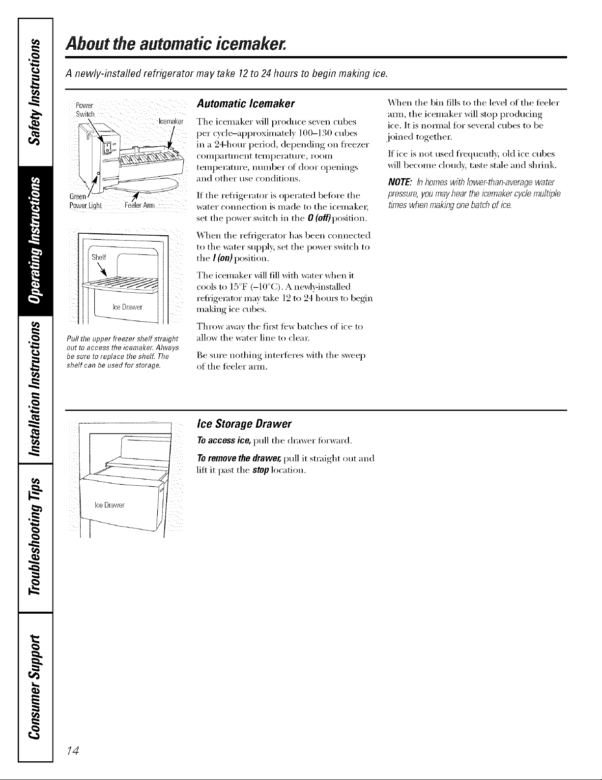
Abouttheautomaticicemaker.
A newly-installed refrigerator may take 12to 24 hours to begin making ice.
Power Automatic lcemaker
Switch
-- Icemaker
Green -- /4r
PeweeLigN EeelerArm
The icemaker will produce se'_en cubes
per c) cle-ai)proxinmtel ) l O0-130 cubes
in a 94-hour period, depending on fl'eezer
COillpai'tlllent teillpei'attli'e, i'OOill
tei/ipei'attli'e, nt/illbei" of door ol)enings
and other use conditions.
If the reti_igerator is operated betore the
water connection is made to the icemake_;
set the power switch in the 0 (off)position.
When the refiigerator has been connected
to the water SUl)ply, set the power switch to
the I (On) position.
The icemaker _fill fill wifl_ water when it
cools to 15°F (-10°C). A newl}qnstalled
refi_igemtor ma)' take 12 h) 24 hotu_ to begfin
making ice cubes.
Throw away the fi_t tew batches ot ice to
Pull the upper freezer shelf straight
out to access the icemaker. Always
be sure toreplace the shelf. The
shelf can be used for storage.
allow the water line to clear
Be sure nothing interteres xfith the sweep
of the teeler am_.
_A]_en the bin fills to the level of the feeler
am/, the icemaker will stop producing
ice. It is nomml for several cubes to be
joined together:
If ice is not used frequenfl 5 old ice cubes
will become cloudy, taste stale and shrink.
NOTE: In homes with lower-than-averagewater
pressure,you mayhear the icemakercycle multiple
times whenmaking onebatch of ice.
Ice Storage Drawer
Toaccessice,pull the drawer fin'ward.
Toremove the drawer, pull it straight out and
lift it past the stop location.
/4

Aboutthe ice and water dispenser.(onsomemodels) GEAppliances.com
ToUse the Dispenser
Select CUBED ICE _, CRUSHEDICE _ Dispenser Light
SpillShelf
or WATER_.
Press tile glass gently against tile top (if
the dispenser cradle.
The spill shelf is not sel6draining.
To reduce water spotting, tile shelf alld LIGHT
its grille should be cleaned regularly,
If no water is dispensed when the refrigerator is
first installed, there may be air in the water line
system. Press the dispenser arm for at least two auick Ice
minutes to remove trapped air from the water
line and to fill the water system. Toflush out
impurities in the water line, throw away the first
slk glassfuls of water
CAUTION: Never put fingers orany other
objects into the ice crusher discharge opening. QUICK ICE
Locking the Dispenser
@ Press tile LOCKCONTROL
1);1(1fO_ 3 seconds to DoorAlarm
lock tile dispenser and
control panel. To
LOCKCONTROL tmlock, press;md
HOLD3SECS hold tile pad again
fin" 3 seconds.
DOORALARM
This pad turns the night
light in the dispenser
on and off'. The light
also COi/les on when
the dispenser cradle is
pressed. If this light
bm'ns out, it should be
replaced with a 6 watt
]2V maximmn bulb.
When vott need ice
in a hurr); press this
pad to speed up ice
production. This will
increase ice production
for the following
4{ghoul_ or until you
press tile pad again.
To set tile ;tl;tllll, pl'ess
this pad tmtil tile
indicator light clm_es
on. This al:mn will
sound if either door is
opel] for/]/o/'e thnn
3 minutes. The light
goes out and the
beeping stops when
you close tile dool;
important Facts About Your Dispenser
i_:Do not add ice fl'om trm:s (:,rbags to
the storage (h'awe_: It may not crush (:,r
dispense well.
>:Avoid oveHilling glass with ice and use of
narrow glasses. Backe&up ice can jam the
chute or cause the door in the chute to
freeze sh lit. If ice is blocking the chute,
poke it through with a wooden spoon.
>: Beverages and foods should not be
quick-chilled in the ice storage drawe_:
Cans, bottles or food packages in the
storage drawer may cause the icemaker
or auger to jam.
i_;:To kee I) dispensed ice fl'om missing
the glass, put the glass close to, but not
touching, the dispenser opening.
i_i;:Some crushed ice may be dispensed
even though you selected CUBED ICE
This happens occasionally when a fray
cubes acddentally get directed to
the crushe_:
_i::_dter crushed ice is dispensed, some
WateI"may drip flxm_ the chute.
i_}:SollletiI//es a small motmd of snow will
timn on the door in the ice chum. This
condition is nomml and usually occms
when you have dispensed crushed ice
repeatedly. The snow will eventually
e\'aporate.
15

Aboutthe ice and water dispenser.
Ice Storage Drawer
on Dispenser Models
Toremove:
Set the k'emaker power switch to the 0 (off)
position. Pull the drawer straight out and
then lift past the stop position.
Toreplace:
_]ten replacing the (h'awe_; be sure to
press it firefly into place. If it does not go
all the way back, i'eillove it and rotnte the
drive mechanism 1/4 tm'n. Then push
the drawer back again,
Careand cleaning of therefrigerator.
Cleaning the Outside
The dispenser drip area, beneath the grille,
should be _ped d_T:_\_ter leit in this area
may lea_e deposits, Remo_e the deposits by
Dispenser drip area.
adding undiluted vinegar to the well, Soak
tmtil the deposits disappear or become
loose enotlgh to I]nse al_;Iv.
The dispenser cradle, getore cleaning, lock
the dispenser by pressing and holding the
LOCK CONTROL pad fi)r 3 seconds, Clean
with warn/water and baking soda
solufion-al)out a tablespoon (l 5 ml) of
baking soda to a quart (l liter) of watei:
Rinse thoroughly and wipe dry:
The deer handles and trim.Clean with
a cloth dampened with soapy water:
Dry with a soft cloth.
Drive
Mechanisn
Thestainless steel panels and door handles
(on SOlne models) can be cleaned with a
commercially available stainless steel
cleaner such as Slainle, s,sSlcr<[,\ l(l_'i_.''_
Slainl_,,_,_Sled Mcg{4cis available at Ace, Tree
Value, Se_Mstm; H_'/and other leading
stores. It is also available through GE Parts
and Accessories, 800.626.2002. Order part
ntli/lbei" _'\]X 10X 15.
Do not use appliance wax or polish on the
stainless steel.
Keep the outside clean. _]pe Mth a clean
cloth lightly dampened Mth kitchen
appliance wax or mild liquid dish detergent.
Dry and polish with a clean, soft cloth.
Do not wipe the refrigerator with a soiled dish
cloth or wet towel Thesemay leave a residue
that can erode the palbt Do not use scouring
pads,powdered c/eanera,bleach or cleaners
containing bleach because these products can
scratch and weaken the paint finish.
/6
Cleaning the Inside
Tohelp prevent odors,leave an (:,pen box ,':,f
baking soda in the fl'esh ti)od and fl'eezer
COI//l)a i'tlllents.
Unplug the refrigerator before cleaning. If this
is not practical, wring excess moisture ()tit
of sponge or cloth when cleaning arotmd
switches, lights or controls.
Use wam_ water and baking soda solution-
about a tablespoon (15 ml) of baking soda
to a quart (1 liter) of water. This both
cleans and neutralizes odms. Rinse and
wipe dry,
Useof any cleaning solution other than that
which is recommended, especially those that
contain petroleum distillates, can crack or
damage the interior of the refrigerator.
Avoid cleaning cold glass shelves with hot water
because the extreme temperature difference
may cause them to break. Handle glass shelves
carefufl_zBumping tempered glass can cause
it to shatter
Donot washanyplasticrefngeratorpartsin the
dishwasher

Behind the Refrigerator
Be careful when moving the refl_igerator
away fl'om the wall. M1 types of floor
coverings can be damaged, particularly
cushioned coverings and those with
embossed S/li]_lces.
Pull the refrigerator straight out and return
it m position by pushing it straight in.
Moving the refl_igerator in a side direction
may result in damage to the floor covering
or reffigerato_:
Preparing for Vacation
For long \;ications or absences, rei//ove
food and uI_plug the refl_igeratoi: Clean the
interior with a baking soda solution of one
tablespoon (15 ml) of baking soda to one
quart (1 liter) of water: i,eave the doo_
open.
Set the icemaker power switch to the 0 (off)
position and shut off the water supply to
the reflJgerato_:
GEAppliances.com
When pushing the refrigerator back, make sure
you don't roll over the power cord or icemaker
supply line.
If the temperature can drop below fl'eezing,
have a qualified servicer drain the water
supply s)'stem to prevent serious propert},
damage due to flooding.
Preparing to Move
Secure all loose items such as shelves and
dI'aweI_ by taping theln securely in place
to prevent damage.
X,_]_en using a hand track to move the
refl_igeratot; do not rest the ti'ont or back
(ff the reti_igerator against the hand truck.
This could damage the refrigerato_: Handle
only fl'om the sides of the reti_igerato_:
Be sure the refn)erator stays/b an upright
position during moving.
/7

Replacingthe lightbulbs.
Setting the controls to OFF does not remove power to the light circuit.
_ Refrigerator Compartment--Upper Light
Unplug the refl'igerator.
0
The bulbs are located at the top of the
@
Tabs
compartment, inside the light shield.
On some models, a screw at the fl'ont of
the light shield will have to be removed.
To t'em(,x e the light shield, press in (m
@
the tabs on the sides of the shield and
slide fi)_'ward and ()tit.
Refrigerator Compartment--Lower Light
O ,Mien" replacing the bulb with an
appliance bulb of the same o_"lower
wattage, replace the light shield and
sci'e_:s (on some models). When
replacing the light shield, make sui'e
that the tabs at the back ot the shield
fit into the slots at the back of the light
shield housing.
Plug the reli_gerato_" back in.
This hght is iocated above the top drawec
O Unphlg the refrigerator'.
0 Remo_e the conve_'tible meat (h'axve_"
control knob b) ptflling straight out.
I.itt the light shield up and ptfll it out.
Freezer Compartment
O Unpltlg the ref'_gerato_:
O Remoxe the shelf just aboxe the light
shield. (The shelf will be easier to
remoxe if it is emptied fi_t.) On some
models, a screw at the top of the light
shield will need to be remoxed.
To remoxe the light shield, press in
on the sides, and lift up and out.
Dispenser
@ _Mtex"replacing the bulb xfith an
appliance btflb of the same o_"lower
wattage, replace the shield and
the knob.
Plug the refrigerator back in.
Replace the btflb with an appliance
O
bulb of the same o_"lowe_" watta(*e
and reinstall the light shield. When
reinstalling the light shield, make
sm'e the top tabs snap secm'elv
into place. Replace the screw
(on some models).
Reinstall the shelf and plt/g the
refrigerator back in.
18
Unphlg the refl_igeratox:
The btflb is located on the dispenser
tin(let" the control panel,
Remove the light btflb by turning
it counterclockwise.
O Replace the btflb with a btflb of the
S[I Ill e size _1 n d tv[l [t_l )e
Plug the refrigerator back in.
Trimkits anddecoratorpanels.
For CustomStgleTM models
Read theseinstructionscompletely and carefully.
BeforeYouBegin
Some models are equipped with trim kits that aflow you to instafl door panels. Youcan order
pre-cut black, white, bisque or stainless steel decorator panels from GEParts and Accessories,
800.626.2002,or you can add wood panels to match your kitchen cabinets.
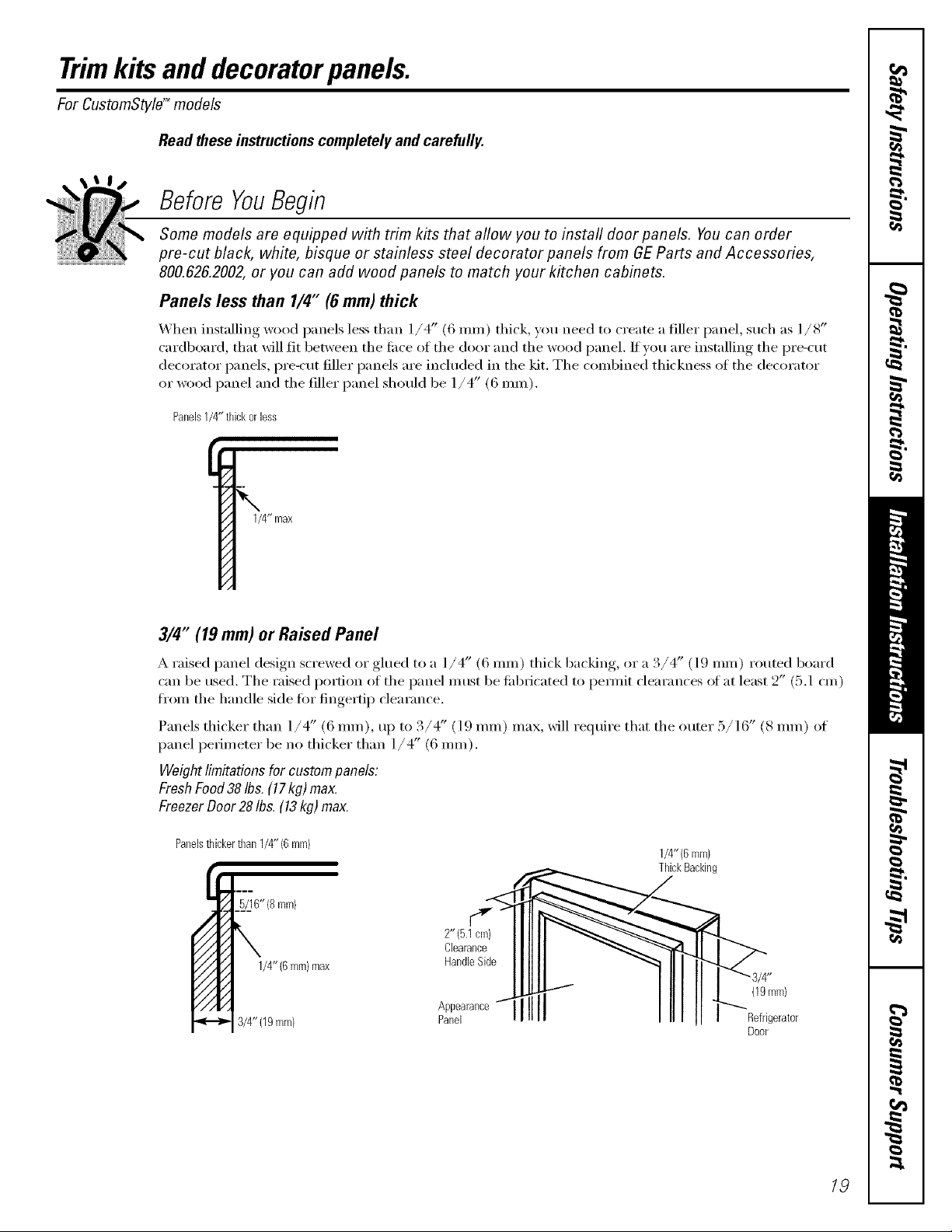
Panels less than 1/4" (6 mm) thick
When installing wood l)anels less than l/4" (6 ram) thick, you need to create a filler panel, such as l/8"
cardboard, that will fit between the fi_ce of the door and the wood panel. If you are installing the l)re-cut
decorator panels, i)re-cut filler panels are included in the kit. The combined thickness of the decorator
or wood panel and the filler panel should be 1/4' (6 ram).
PanelsI/4" thickorless
1/4"max
3/4" (19 mm) or Raised Panel
A raised panel design screwed or glued to a ]/4" (6 ram) thick backing, or a 3/4" (] 9 ram) routed board
can be rise(1. The raised l)ortion of the l)anel ii/tlSt be tid)ricated to l)ennit clearances of at least 2" (5.1 cm)
from the handle side for fingertip clearance.
Panels thicker than 1/4" (6 ram), u I) to 3/4" (l 9 ram) max, will reqtfire that the outer 5/16" (8 ram) of
panel perimeter be no thicker than 1/4" (6 ram).
Weightlimitationsfor custompanels:
FreshFood38Ibs.(17kg)max.
FreezerDoor28Ihs.(13kg)max.
Panelsthickerthan1/4"(6 mm)
2"(5.1 cm) II !lll __----..._>,4.._
Clearance I I I]11 _"
3/4"(19mm) pApp:_ra,,ceq1111 • tor
1/4"(6mm)
ThickBacking
Door
19
Trimkits anddecoratorpanels.
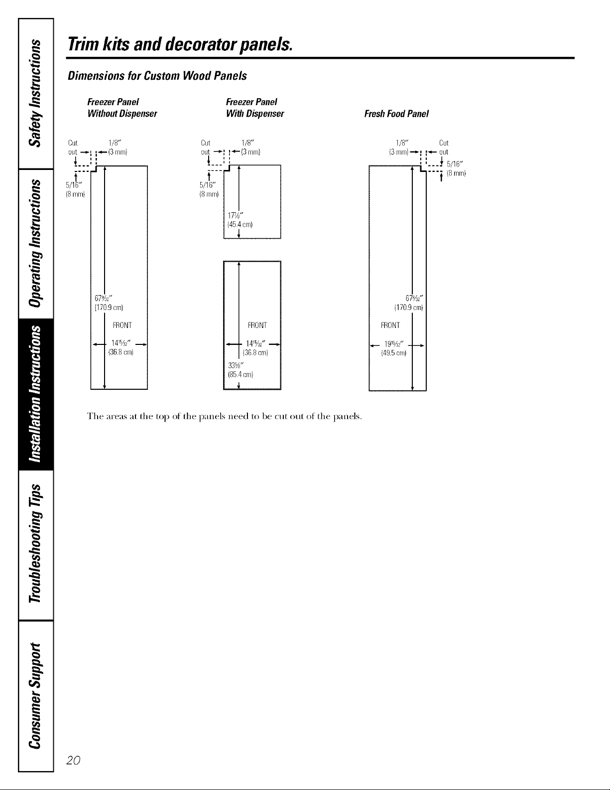
Dimensions for Custom Wood Panels
FreezerPanel
WithoutDispenser
Cut 1/8"
out "-_I --(3mm)
t
5/16"
(8mm}
67_S'
(170.9cm)
_ i 141_2"
(36.8cm)
FRONT
FreezerPanel
WithDispenser
Cut 1/8"
out --_f f_'-(3 ram)
''
i i
177A,'
(45.4cm)
!
FRONT
. 141%Z"
(36.8cm)
33%"
(85.4cm)
{
FreshFoodPanel
1/8" Cut
(3mm)--_f f_,- out
FRONT
_,_ 191%2" _.__.
(49.5cm)
67_Z'
(170.9cm)
''
' ' 5/16"
/
""{ (8ram)
The areas at the top of the panels need to be cut out of the panels.
20

Insertingthe doorpanels.
Read these instructions completely and carefully.
0 Insert the Freezer Panel and FreshFood Panel
(_arefully push the ti'eezer panel in until it slides If your model has a dispenser, this step only applies
into the slot behind the door handle. Push the filler to the fl'esh fi_od panel and top fl'eezer panel.
panel (required with some door panels) in behind
the decorator panel. Repeat fin" fl'esh fi)od panel.
0 Insert the Bottom Freezer Panel (on dispenser models).
(_arefull_ push the panel in until it slides into the (required with some door panels) in behind the
slot behind the door handle. Push the filler panel decorator panel.
Attach the TopTrimon the Freezer and Fresh Food Doors.
The Top Trim can be tound inside the reii_igerator each (looi; Hand tighten only: Make sm'e that the
compartment, top of each panel fits snugly behind the lip of the
_,_]th a T-20 Torxdrive_; am_ch the Top Trim, using Top Trim.
two scre_:s on each Top Trim piece, to the top oI
Cut-Out
SideTrim
21

Insertingthe doorpanels.
O Install the Side Trim.
These pieces are tucked inside the reti_gerator
door handle,
Donot removetheprotectivefilm on the outsideof
theSideTrimuntil theSideTrimis instated.
Fit the bottom of the Side TFim under the
Bottom TFim as illustrated,
Hold the Side TFim against the fl'ont fi_ce of the
decorator panels and fit the Side TYim under
the Top TFim, Make sure the magnetically attached
Side TYim is fitted correctly and that you are
satisfied with the appearance of all the parts.
22
Removingandreplacing the doors.
When installing or moving the refrigerator, the doors may need to be removed in order to fit the refrigerator
through a doorway.
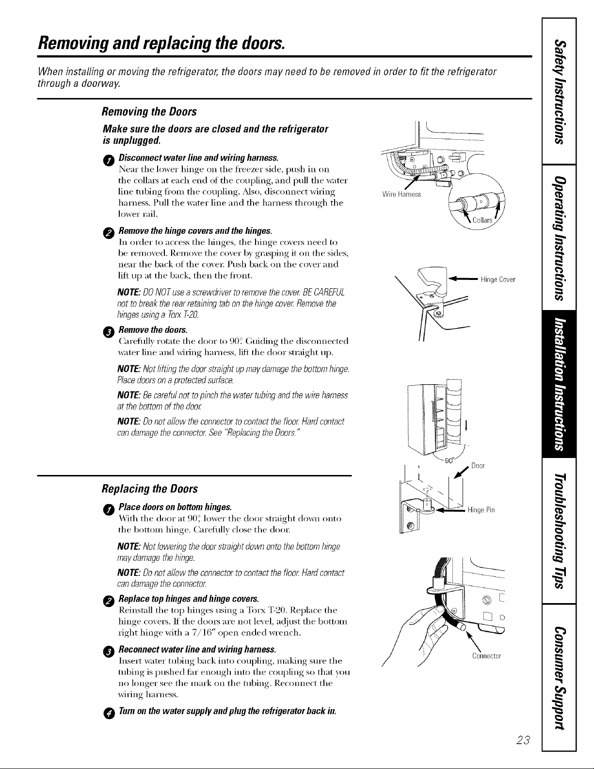
Removing the Doors
Make sure the doors are closed and the refrigerator
is unplugged.
0 Disconnect water line and wiring harness.
Near the lower hinoe_ on the fl'eezer side, push in on
the collm_ at each end ot the coupling, and pull the water
line robing fl'on/the coupling. _Mso, (liscmmect wiring
harness. Pull the water line and the harness through the
lower rail.
0 Remove the hinge covers and the hinges.
In order to access the hinges, the hinge covers need to
be removed. Remove the cover by grasping it on the sides,
near the back of the covei: Push back on the cover and
lift up at the back, then the front.
NOTE: DONOTusea screwdriverto removethe cover BECAREFUL
not tobreaktherear retaining tab onthehingecover Removethe
hbges usbg a TorxT-20.
Remove the doors.
(:arefhllv rotate the door to 90? (;uiding the disconnected
water line and wiring harness, lift the door straight up.
NOTE: Not/i@bg the doorstraight upmay damagethebottom hinge.
Piecedoorsona protectedsurface.
NOTE: Becareful not to pinch the water tubingand the wire harness
at thebottom of the door
NOTE: Donot allow the connectorto contact the floor Hardcontact
can damagetheconnector See"Replacingthe Doors."
WireHarness%
-- HingeCover
Replacing the Doors
Place doors on bottomhinges.
_Mth the door at 90 ° lower the door straight down onto
the bottom hinge. Careflflly close the (loo_:
NOTE: Not/owenng the doorstraight down onto thebottom hinge
may damagethe hinge.
NOTE'.Donot allow the connectorto contact the floor Hardcontact
can damagetheconnector
Replace top hinges and hinge covers.
Reinstall the top hinges using a Torx T-20. Replace the
hinge covers. If the doms are not level, a@_st the bottom
right hinge with a 7/16" open ended wrench.
_) Reconnect water line and wiring harness.
Insert water tubing back into coupling, making sure the
tubing is pushed flu" enough into the coupling so that you
no longer see the mark on the robing. Recmmect the
wiring harness.
Turnon the water supply andplug the refrigerator hack in.
Door
HingePin
Connector
23

Installation
Refrigerator
Instructions
Models23,25, 27 & 29
Questions?Call800.GE.CARES(800.432.2737)or Visit,m,X_ebsite,t: GEAppliances.comIn Canada.call 1.800.361.3400or Visit,,u X_ebsite,t: geappliances.ca I
BEFORE YOU BEGIN
Read these instructions completely and carefully.
• IMPORTANT - S.ve hese
instructions flw local inspector's use.
•IMPORTANT - Obse,,e.11
go" erning codes and ordinances.
• Note to Installer - Be sure to leave these
instructions with the Consumer.
• Note to Consumer - Kee I, these instructions
fl)r future re_erence.
CLEARANCES
Mlow the tolhm'ing clearances tot ease of installation,
proper air ciroflation and I'hunbing, and electrical
connectioils:
23' 25', 27' mad 29'
• Sides 1/8" (4 mm) 1/8" (4 mm)
• Top 1" (25 ram) 1" (25 ram)
• Back 1/2" (13 ram) 1" (25 ram)
ROLLERS
• SMll level - Installation of this appliance requires
basic mechanical skills.
• Completion time - Refrigerator Installation
15 minutes
• Proper installation is the responsibility of the
installe_=
" Product thilure due to improper installation is not
covered under the Warranty.
WATER SUPPLY TO THE ICEMAKER
(ON SOME MODELS)
The rollers have 3 purposes:
• RolleI_ a_!just so the door closes easily when opened
about hallway: [Raise the ti'ont about 5/8" (l 6 ram) ti'om
the tlooi:]
Rollels ac!iust so the refi_igerator is firefly positioned on
the floor aml does not wobble.
• Rollels alhm' w)u to m_we the refrigerator away from the
wall tot cleaning.
Final leveling a(!it,stulents should be made atter the
refrigerator has been installed.
It the reli'igerator has an icemaker, it will have to be
connected to a cold water line. A GE water supply kit
(containing tubing, shutoff wdve, fittings and
instructions) is awfilable at extra cost fl'om yore" dealer,
by visiting ore" X,Vebsite at GE&pplimlces.com (in
Canada at geapplimaces.ca) or fl'om Parts and
Accessories, 800.626.2002 (in Canada 1.888.261.3055).
REFRIGERATOR LOCATION
• Do not install the refl_igerator where the temperatm'e
will go below 60°F (l 6°C) because it will not run otten
enough to maintain proper temperatm'es.
• Do not install the refrigerator where the temperature
will go above 100°F (37°(;) because it will not pe_imn
properl>
• Install it on a floor strong enough to support it hilly
loaded.
To adjust the rollers on 25', 27' mid 29' models:
Ttu'n the roller
adiustino screws
dockwise to raise
the reffigeratm;
comaterclockMse to
lower it. Lrse a 3/8"
hex socket or wI'ench,
OI" _111 a({iustnble
wI'ench.
24
L__
X
Rolleradjustingscrew
Installation Instructions
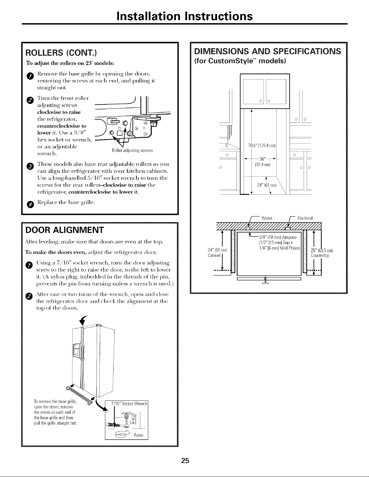
ROLLERS {CONT.)
To adjust the rogers on 23' models:
O Remove tile base grille by opening tile doo_,
removing the screws at each end, and pulling it
straight out.
O Turn the fl'ont roller
adjusting screws
dockwise to raise
tile refi_igerato_;
eomaterclockwise to
lower it. Use a 3/8"
hex socket or wrench,
or an adjustable
wrench. Roileradjusting screws
These models also have rear a(!justable rollers so you
can align the refiigerator with yore" kitchen cabinets.
Use a long-handled 5/16" socket wrench to turn the
scrmvs tot the rear rolle_dockwise to raise the
refiigerato_; cotmterclockwise to lower it.
O Replace tile base grille.
DIMENSIONS AND SPECIFICATIONS
(for CustomStyle TM models}
o o
.....2 £ .....
70¼"(178.4cm)
o
o
" 36"_
(91.4cm)
.......................................24" (61fm)_.................
Water Electrical
DOOR ALIGNMENT
_M[er leveling, make sure that doors are even at tile top.
To maim the doors even, a(!iust tile reiiigerator door.
Using a 7/16" socket _,_rench, ttWll tile door ac{}usting
screw to the fight to raise tile doo_; to tile left to lo*_er
it. (A nylon plug, imbedded ill tile threads oi the pin,
prevents tile pin from turning unless a wrench is used.)
O _[el" ()lie o1"two [tll'llS 1)]_tile "_l'ench, opell _|lld close
tile refligerator door and check tile aligmnent at tile
top _g tile dool_.
:_:gz.:
Toremovethe basegrille,
openthedoors,remove
tbescrewateacbendof
thebasegrilleandthen
pullthegrille straightout.
_[1_//16" Socketjrerlc]tl]
/4" (19ram)Airspace
(1/2"[13mm]Gap+
24" (61cm) 1/4" [6miniWall Plates) 1.5cm)
Cabinet Countertop
' 2C 1
@_7> Raise
25
Installation Instructions
iNSTALLiNG THE WATER LiNE IoNSOMEMODELS)
BEFORE YOU BEGIN
Recommended COl)per water supply kits are _,\_NSX2,
_X8X3 or _X8X4, depending on the amom_t of tubing
you need. Approved plastic water sui)ply lines are GE
SmartConnect ''_Refrigerator Tubing (_._X08X10002,
_._5X08X10006, _._5X08X10015 and WX08X10025).
When connecting yore" refl_igerator to a GE Reve_e
Osmosis Water System, the only approved installation is
with a GE RVKit. For other reve_e osmosis water systems,
follow the inanttfilcturer's recolmnendations.
If the water sui)ply to the reti'igerator is from a Revelse
Osmosis _,Vater Filtration Svstem AND the refrigerator
also has a water filter, use the refl'igerator's filter bypass
plug. Using the refl'igerator's water filtration cartridge
in conjm_ction with the RO filter can result in hollow
ice cubes and slower water flow from the water
dispenser.
This water line installation is not warranted bv the
refrigerator or icemaker manufi_cturer. Follow these
instructions carefifllv to minimize the risk of expensive
water damage.
Water hammer (water banging in the pipes) in house
plmnbing can cause damage to refrigerator parts and
lead to water leakage or flooding. (:all a qualified
plmnber to correct water hammer before installing the
water supply line to the refl'igerator.
To prevent bm'ns and product damage, do not hook
up the water line to the hot water line.
If wm rise your refrigerator beti)re connecting the
water line, make sm'e the icemaker power switch is in
the 0 (off) position.
Do not install the icemaker tubing in areas where
temperatures fall below fl'eezing.
When using anv electrical device (such as a power
drill) dm'ing installation, be sure the device is double
insulated or grotmded in a manner to prevent the
hazard of electric shock, or is battery powered.
All installations inust be in accordance with local
l)ltm_bing code reqtfirements.
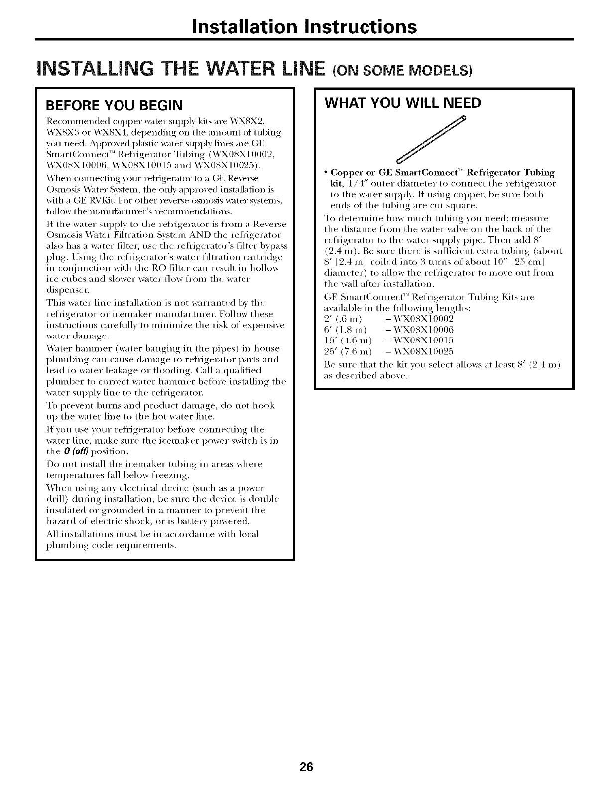
WHAT YOU WILL NEED
J
• Copper or GE SmaactCommc('" Refrigerator Tubing
kit, 1/4" outer diameter to connect the refl'igerator
to the water supply: If using COl)per, be sure both
ends of the tubing are cut square.
To detem_ine how much tubing you need: measure
the distance fl'om the water wove on the back of the
refl'igerator to the water supply pipe. Then add 8'
(2.4 m). Be sm'e there is sufficient extra tubing (about
8' [2.4 m] coiled into 3 turns of about 10" [25 cnl]
diameter) to allow the refrigerator to move out fl'om
the wall alier installation.
GE Smart(_onnect'" Refl'igerator Tubing Kits are
awfilable in the fi_llowing lengths:
2' (.6 m) - WXO8XIO002
6' (1.8 m) - WXO8XIO006
15' (4.6 m) - WXO8XIO015
25' (7.6 m) - _T_O8XlO025
Be sure that the kit wm select allows at least 8' (2.4 in)
as described above.
26

Installation Instructions
WHAT YOU WILL NEED (CONT.)
NOTE: The only GE approved plastic tubing is that
supplied in GE SmartCmmect T"Refrigerator Tubing
kits. Do not use may other plastic water supply fine
because the line is under pressure at all times. Certain
types of plastic will crack or rupture with age and
cause water dmuage to your home.
• AGE water supply kit (containing tubing, shutoff
valve and fittings listed below) is available at extra
cost ][I'OIIl VO/U" dealer or ti'om Parts and Accessories,
800.626.2002 (in Canada 1.888.261.3055).
• A cold water supply. The water pressm'e must be
between 20 and 120 p.s.i. (1.4-8.1 bar).
• Power drill.
• 1/2" or adjustable wrench.
• Straight mid Phillips blade screwdriver.
Install tile shutoff valve on tile nearest frequently used
drinking water line.
[] SHUT OFF THE MAIN WATER
SUPPLY
Turn on the nearest faucet hmg enough to clear
tile line of water.
[] CHOOSE THE VALVE LOCATION
Choose a location fi)r tile valve that is easily
accessible. It is best to connect into tile side of a
vertical water pipe. When it is necessary to connect
into a horizontal water pipe, make tile connection
to tile top or side, rather than at tile bottom,
to avoid drawing off any sediment from tile
water pipe.
• Two 1/4" outer diameter compression nuts and
2 ferrules (sleeves)-to connect tile copper tubing
to tile shutoff wdve and tile refl'igerator water
wdve.
OR
• If wm are using a GE Sulart(_.onnect TM Refl'igerator
Tubing kit, tile necessary fittings are preassembled to
tile robing.
• If your existing copper water line has a flared fitting
at the end, you will need an adapter (awfilable at
phunbing supply stores) to connect the water line to
tile reli'igerator OR you can cut off tile flared fitting
with a tube cutter and then use a compression fitting.
Do not cut fl)rmed end fl'om GE SmartConnect'"
Reii'igera tot robing.
• Shutoff valve to connect to tile cold water line.
The shutoff wdve should have a water inlet with a
minim um inside diameter of 5/32" at the point of
connection to the COLD WATER LINE. Saddle-type
shutoff wdves are included in many water sui)ply kits.
Before purchasing, make sure a saddle-type wdve
complies with your local phunbing codes.
[] DRILL THE HOLE FOR THE VALVE
Drill a 1/4" hole in tile water pipe (even if usino,_ a
sell=piercing xalxe), using a sharp bit. Remoxe anx
burrs resulting from drilling,, the hole in the pipe.
Take care not to allow water to drain into the drill.
Faihu'e to drill a 1/4" hole max result in reduced
ice production or smaller cubes.
27

Installation Instructions
INSTALLING THE WATER LINE (CONT.)
[] FASTEN THE SHUTOFF VALVE
Fasten tile shutoff _al_e to tile cold water pipe with
tile pipe clamp.
Pipe
Saddle-Type'"_ ColdWater Pipe
ShutoffValve
NOTE: Conm_onwealth of Massachusetts Plumbing
Codes 248CMR shall be adhered to. Saddle wflves
are illegal and use is not pemfitted in Massachusetts.
Consult with wmr licensed i)lmnber.
[] TIGHTEN THE PIPE CLAMP
Tighten tile clamp screws tmtil tile sealing washer
begins to swell.
NOTE: Do not overtighten or w)u may c_ush tile
tubing.
Pipe
Clamp
Screw_
Washer
Inlet End
r •
[]
CONNECT THE TUBING TO THE
VALVE
Place tile compression nut and teHule (sleeve)
for COl)per tubing onto tile end of tile tubing and
connect it to tile shutoff valve.
Make sm'e tile tubing is flflly inserted into tile valve.
Tighten the compression nut secm'elv,
For plastic tubing fl'om a GE SmartConnect ''_
Refl'igerator Tubing kit, insert the molded end
of the tubing into the shutoff' wflve and tighten
compression nut until it is hand tight, then tighten
one additional turn with a wrench. Overtightening
IIl[IV Catlse leaks.
I
Saddle-TypeShutoffValve I CompressionNut
SmartConnectTM
PackingNut
OutletValve
NOTE: (_onllnonwealth of Massachusetts Plulnbing
(:odes 248(:MR shall be adhered to. Saddle wflves
are illegal and use is not pemfitted in Massachusetts.
Consult with vom" licensed plmnber.
[] FLUSH OUT THE TUBING
Ferrule(sleeve)
[] ROUTE THE TUBING
]_.oute tile tubing between tile cold water line and
tile refl'igera tot.
Route tile tubing through a hole drilled in tile wall
or floor (behind tile refl'igerator or a(!jacent base
cabinet) as close to the wall as possible.
NOTE: Be sure there is sufficient extra tubing
(about 8' [2.4 m] coiled into 3 turns of about
10" [25 cm ] diameter) to allow tile refrigerator
to move out fi'om the wall atter installation.
Tm'n tile main water sui)ply on and flush ()lit tile
tubing until tile water is clear.
Shut tile water off at tile water valve alter about
one quart (l liter) of water has been flushed
through tile tubing.
28

Installation instructions
[] CONNECT THE TUBING TO THE
REFRIGERATOR
NOTES:
• Before making tile connection to tile refl'igerator,
be sure tile refl'igerator power cord is not i)lugged
into tile wall outlet.
• If your refl'igerator does not have a water filteL
we recommend installing one if yore" water
supply has sand or particles that could clog tile
screen of the reti'igerator's water valve. Install it in
tile water line near tile reli'igerator. If using (;E
SmartConnect _''Refl'igerator Tubing kit, you will
need an additional tube (WX08X10002) to
connect tile filter. Do not cut plastic tube to
install filter.
Some models have the refl'igerator connection at
the end of tubing located outside the compressor
COUll)ai'tulent access cover. On other models, tile
COUll)I'eSSOI" COU/l)aI'tII/ent access cover UltlSt be
removed in order to access the reti'igerator
connection at tile water wllve.
[] CONNECT THE TUBING TO THE
REFRIGERATOR (CONT.)
Insert tile end of tile tubing into tile water valve
connection as tar as possible. While holding tile
tubing, tighten tile fitting.
For plastic tubing fl'om a GE SmartConnect _''
Refl'igerator Tubing kit, insert the molded end
of the tubing into the refl'igerator connection and
tighten the compression nut until it is hand tight,
then tighten one additional turn with a wrench.
Overtightening may cause leaks.
Fasten the tubing into the clamp provided to hold
it in a vertical position. You may need to I)_T open
tile clamp.
One of the illustrations below will look like the
connection on your refrigerator.
Tubing 1/4"
1/4"
Compression\
Nut
Ferrule
On models usin,* tile refrigeration connection at
tile water xalxe, remoxe tile plastic flexible cap.
©
Place tile compression nut and terrule (sleeve)
onto tile end of tile tubing as shown. On tile GE
SmartConnect'" Refl'igerator Tubing kit, tile nuts
are ah'eady assembled to tile tubing,
SmartConnect_
Tubing
TubingClamp
1/4"
CompressionNut
Ferrule
(sleeve)
Refrigerator
Refrigerator
Connection
1/4"Tubing
SmartConnect_ Tubing
29

installation instructions
INSTALLING THE WATER LINE (CONT.)
[] TURN THE WATER ON AT THE
SHUTOFF VALVE
Tighten any connections that leak.
Replace access co_ei'.
[] PLUG IN THE REFRIGERATOR
Arrange tile coil ot tubing so that it does not _ibrate
against tile back of tile refrigerator or against tile
wall. Push tile refl'igerator back to tile wall.
START THE ICEMAKER
Set tile icemaker power switch to tile / (on) position.
Tile icemaker will not begin to operate until it
reaches its operating temperature of 15°F (-9°C)
or below. It will then begin operation automatically
if the icemaker power switch is ill the ! (on) position.
NOTE: In lower water pressm'e conditions, tile
*_ater val_e ma_ turn on up to 3 times to deliver
ellO/ioh x#atel" to tile icemaker.
30
 Loading...