

GE PSS27NGMAWW, PSS27NGMACC, PSS27NGMABB, PSS27NGMAAA, PSS25SGMDBS Owner’s Manual
...
GEApp/iances.com
Safety Instructions ........... 2-4
°v,,,,_
U3
Operating Instructions
Additional Features ............ ] ]
Automatic Icemaker ........... 13
Care and Cleaning .......... 15, 16
CustomCool TM ............... 6, 7
Ice and _'ater Dispenser ..... 14, 15
Refligerator Doors ............ 11
Replacing the lightbulbs ........ 17
Shelves and Bins ............ 9, 10
Crispers and Pans ............. 12
Temperature Controls ........... 5
_'ater and FreshSaver TM Fihers .... 8
Installation Instructions
Preparing to Install
the Refligeramr ............ 24, 25
Removing and Replacing Doors . .23
Trim I_Sts and Panels ........ 18-22
_'ater Line Installation ...... 26-30
Troubleshooting Tips ....... 32-34
Normal Operating Sounds ...... 31
Models21,23,25,27,and29
Profile C6te _ C6te
R6frig6rateurs
La section frangaise commence a la page 42
Profile Lado a Lado
Refrigeradores
La secci6n en espafiol empieza en la pagina 78
Consumer Support
Consumer Support ..... Back Cover
Performance Data Sheet ........ 37
Product Registration ........ 39, 40
State of California Water
Treatment Device Certificate ..... 38
h'arranty (Canadian) ........... 35
_'arrantv (U.S.) ............... 36
Write the model and serial numbers here:
Model #
Serial #
Find these numbers on a label inside
the reti'igerator compartment at the
top on the right side.
200D2600P010 49-60158 07-01JR

IMPORTANTSAFETYINFORMATION.
READALLINSTRUCTIONSBEFOREUSING.
A WARNING!
Use this appliance only for its intended purpose as described in this Owner's Manual
SAFETYPRECAUTIONS
When using electrical appliances, basic safety precautions should be followed, including the following:
_,':;This refl-igerator must be properly installed
and located in accordance with the Installation
h_structions beiore it is used.
_,':;Do not allow children to climb, st;rod or hang
on the shelves in the refl'igerato_: They could
damage the refligerator and seriously iqim'e
themselves.
:)::Do not touch the cold surli_ces in the fl'eezer
compartment when hands are damp or wet. Skin
may stick to these extremely cold sm_thces,
i,;:Do not store or use gasoline or other flammable
\:q_ms and liquids in the vicini F oI this or any
other appliance.
i,_:_In refiigerato_s with atltOll/atic icemake_s,
avoid contact with the moving parts of the
ejector mechanism, or with the heaOng element
locamd on the bottom of the icemake_: Do not
place finge_ or hands on the aUtOlnatic
icemaking mechanism while the refl_igerator
is plugged in.
i/:;Keep finge_s out _ff the "pinch point" areas;
clearances between the dom_ and between
the (loo_ and cabinet are necessarily small.
Be careful closing doms when children are
in the area.
i/:;Unplug the refl'igerator befin'e cleaning and
making repairs.
NOTE."We stronglyrecommendthatany servicingbe
performedby aquafified individual
i,_:_Setting either or both controls to 0 (0€/) does not
remove power to the light circuit.
::NDo not refl'eeze fl'ozen tbods which have
thawed completely.
_,ZMwavs clean the CustomCooIrMTray after thawing
tOod.
2
vvvvw.GEAppliances.com
DANGER!RISKOFCHILDENTRAPMENT
PROPERDISPOSALOFTHEREFRIGERATOR
Child entrai)ment and suffocation are not i)rol)lems
of the past, Junked or abandoned refl_igeratm_ are
still dangerous...even if they will sit fin" "just a fi_w
days." If you are getting rid of yore" old refrigeratm;
please follow tile instructions below to hel I) prevent
accidents.
Before YouThrowAway YourOldRefrigerator
or Freezer:
i;_?Take off tile dome.
CFCDisposal
Ymr old refl_igerator may have a cooling system
that used CFCs (chlorofluorocarbons). CFCs are
believed to ham_ stratospheric ozone.
If you are throwing away yore" old refrigerator; make
sm'e tile CFC refl_igerant is removed fin" proper
disposal by a qualified se_wice_: If you intentionally
release this CFC reflJgerant you can be subject to
fines and imprisomnent under provisions of
enviromn ental legislation.
>_ I,eave tile shelves in place so that children max
not easilx climb inside.
USEOFEXTENSIONCORDS
Because of potential safety hazards under certain conditions, we strongly recommend against the use
of an extension cord.
However, ifxou must use an extension cord, it is absolutelx necessary that it be a UITlisted (in tile United
States) or a (;SA-listed (in (_anada), 3-wire grom_ding type appliance extension cord haxim,_ a ,gr°m_ding
type I)hw_ and outlet and that tile electrical rating, of tile cord be 15 amperes (minimum) and 120 xolts.

IMPORTANTSAFETYINFORMATION.
READALLINSTRUCTIONSBEFOREUSING.
WARNING!
HOWTOCONNECTELECTRICITY
Do not, under any circumstances, cut or remove the third (ground) prong from the power cord. For
personal safety this appliance must be properly grounded.
The power cord of this appliance is equii)ped with
a 3-prong (grounding) plug which mates with a
standard 3-prong (grotmding) wall outlet to
minimize the possibili F of electric shock hazard
fl'om this appliance.
Have the wall curet and circuit checked by a
qualified electridan to make sure the outlet is
i)roi)erly gromMed.
If the outlet is a stnndard 2-prong outlet, it is your
personal resi)onsibility and obligation to have it
replaced with a i)roperly grotmded 3-prong wall
outlet.
The refl-igerator should always be plugged into its
own indi_i(lual electrical outlet which has a _oltnge
rating that matches the rating plate.
This provides the best perflmnance and also
I)rexents oxerloading, house wiring circuits which
could cause a fire hazard fl'om oxerheated wires.
Never unplug yore" refl_igerator by pulling on tile
power cord. Mways grip plug firefly and pull
straight ()lit fl'onl the outlet.
Repair or replace immediately all power cords that
have become fl'aved or otherwise damaged. Do not
use a cord that shows cracks or abrasion damage
along its length or at either end.
\._]/en moving tile refi_igemtor away ti'om tile
wall, be careflfl not to roll over or damage tile
power cord.
USEOFADAPTERPLUGS(Adapte_plug_notpe_mittedinca_odo)
Because of potential safety hazards under certain conditions, we strongly recommend against
the use of an adapter plug.
Howe\'et; if' you, must use an adapter; where local
codes pemfit, a temporary connection may be made
to a i)roperly grotmded 2-prong wall outlet by use
of a Lri Aisted adapter a\:lilable at m()st local
haYdwaI'e stores,
Tile linger slot in tile adapter must be aligned Mth
the larger slot in the wall outlet to provide proper
polari F in tile com_ecfion of tile power cord.
When (lisc(mnecting tile power cord fl'om tile
adapte_; always hold tile adapter in place with one
hand while pulling tile power cord plug with tile
other hand. If this is not done, tile adapter gromM
temfinal is very likely to break with repeated use.
If the adapter grotmd temfinal breaks, DO NOT
USEthe refrigerator tmtil a proper grotmd has
been established.
Attaching the adapter ground terminal to a waft outlet
cover screw does not ground the appliance unless the
cover screw is metal, and not ihsu/ated, and the waft
outlet is grounded through the house wiring. Youshould
have the circuit checked by a qualified electrician to make
sure the outlet is propeHygrounded
READANDFOLLOWTHISSAFETYINFORMATIONCAREFULLY.
SAVETHESEINSTRUCTIONS
4

Aboutthe temperaturecontrols, vvvvw.GEAppliances.com
The temperature controls are preset in the factory at 37°t: for the
refrigerator compartment and O°Ffor the freezer compartment. Allow
24 hours for the temperature to stabilize to the preset recommended
settings.
The temperature controls can display both the SET temperature
as well as the actual temperature in the refrigerator and freezer.
The actual temperature may vary slightly from the SET temperature
based on usage and operating environment.
Setting either or both controls to OFFstops cooling in both the freezer
and refrigerator compartments, but does not shut off electrical power
to the refrigerator.
J
NOTE: Therefrigerator is shipped with protective film covering the
temperaturecontro/s, if this fi/m was not removedduring installation,
removeit now.
Tochange the temperature, press and release tile
WARMER or COLDERpad. Tile SETlight will come
on and tile display will show tile set temperature.
To change tile temi)erature, tap either tile
WARMER or COLDERpad tlntil tile desired
temperature is displayed. Refrigerator temperatures
can be a(!justed between 34°F and 44°F and tile
fl'eezer temperatures can be a(!iusted between
-6°F and +6°E
Once tile desired temperature has been set,
the temperature display will return to the actual
retiigerator and fl'eezer temperatures after
5 seconds. Several a(!itlstments may be required.
Each time you a(!iust controls, allow 24 l/o/us
fin" tile reliJgerator to reach tile temperature
VO/Ihave set.
Toturn the cooling system off,tap tile WARMER pad
tot either tile reti'igerator or tile fl'eezer until tile
display sho_vs OFF.To turn the unit back on, press tile
COLDERpad tin" either tile refl_igerator or freezer,
The SETlight will illuminate on the side you
selected, Then press the COLDERpad again (on the
side where the S_'Tlight is illuminated) and it will
go to tile preset points of O°Ffi)r tile fl'eezer and
37°Flor tile reliiger:mn: Setting either or both
controls to OFFstops cooling in both tile fl'eezer
and refrigerator compartments, but does not shut
off electrical power to the retiigerato_:
PerformanceAir FlowSystem
Tile Perf0mmnce M_=Flow System is designed to
maximize temperature control in tile refrigerator
and ti'eezer compartments. This unique special
t_'ature consists of tile AJr Tower along tile top and
back walls of tile refrigerator and tile Mr Tunnel on
the bottom portion ot the fl'eezer rear wall, Placing
fi)od in fl'ont of tile louve_ on these components
will not affect pedinmance. Mthough tile Mr Tower
and tile Mr Tunnel can be removed, doing so Mll
affect temperature pe_ommnce. (For remowd
instructions, on-line, 24 ho/u_ a day, contact us at
_sv.GEAppliances.com or call 800-GE-CARES.
In Canada, contact us at _v.geappliances.ca or
call 1.800.361.3400.)

AboutCustomCool7
How it Works
The CustomCooITMfi_atm'eis a systeIIl OI
daml)e_, a tim, a teml)eratm'e them/isto_;
and a heate_: Depending on the flmction
selected, a combination ot these will be
used to quickly chill items, thaw items or
hold the pan at a specflic temperature.
How to Use
The pan is tightly sealed to prevent the pan's
teml)eramre fl'om causing temperature
fltlCttlations in the rest (ff the reliigerato_:
The controls for this pan are located at the
top (ff the refrigerator with the temperature
conti'ols.
ExpressThawTM
ExpressChillTM
Empty the pan. Place the Chill/Thmv
tray in the pan with the metal plate
timing down to chill and store items, or
with the metal })late ihcing up to thaw
items. Place the items on the tray and
close the pan completely.
@ Select the ExpressThaw TM,
ExpressChill or Selectremp i)ad.
The display and SETlight will come on.
Tap the pad until the light a})l)ea_ next
to the desired setting. Llse the chm_ to
detem_ine the best setting to use.
N To stop a teatm'e betore it is
finished, tap that teamre's pad
tmtil no options are selecmd and
the display is off.
i_;: During ExpressThawrMand
ExpressChill , the displa_ on the
controls will cotmt down the time
in the cycle.
TM TM
TM
_i:: _Mier the ExpressThawrMcycle is
complete, the pan will reset to the
MEATsetting (30°F) to hel I) preserve
thawed items tmtil they are used.
i_i;:The displayed actual temperature of
the CustomCoolpan may \m T slightly
fl'om the SET temperature based on
usage and operating enviromnent.
NOTE:For food sale F reasons, it is
recommended that toods be wrapped
in plastic wrap when t/sin(r_ ,, ExpressThaw TM
This will hel I) contain meat juices and
improve thawing pertimnance.
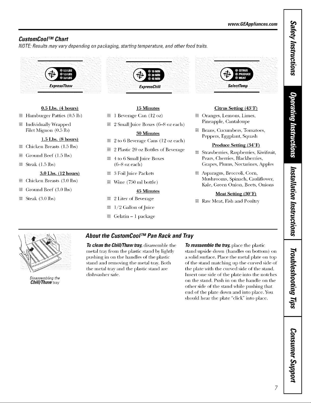
CustomCoolTM Chart
NOTE:Resultsmay vary depending on packaging, starting temperature, and other food traits.
vvvvvv.GEAppliances.com
0.5 Lbs. (4 hours)
;i:: Hambmger Patties (0.5 lb)
>: Individually Wrapped
Filet Mignon (0.5 lb)
1.5 Lbs. (8 hours)
i_? Chicken Breasts (1.5 lbs)
i_: Ground Beef (1.5 lbs)
i;_;:Steak (1.5 lbs)
3.0 Lbs. (12 hours)
i_: Chicken Breasts (3.0 lbs)
i_? Gro/md Beef (3.0 lbs)
>: Steak (3.0 lbs)
Disassembling the
Chill/Thaw tray
15 Minutes
;i:: 1 Beverage Can (12 oz)
;i:: 2 Small Juice Boxes (('_8 oz each)
30 Minutes
i_;: 2 to 6 Beverage Cans (l 2 oz each)
i_i: 2 Plastic 20 oz Bottles of Beverage
i_;: 4 to 6 Small,Juice Boxes
(6--8 oz each)
;i:: 3 Foil Juice Packets
_i:: Wine (750 ml bottle)
45 Minutes
_i:: 2 Liter ot Beverage
i_;: 1/2 Galhm ot,]uice
>: Gelatin- 1 package
About the CustomCoolTM Pall Rack and Tray
Toclean #le Chill/Thaw tray, disassemble tile
metal tray flxnn tile plastic stand by lightly
pushing in on the handles ot the plastic
stand and removing the metal tray. Both
the metal tray and the plastic stand are
dishwasher sate.
Toreassemble the tray, place tile plastic
stand upside down (handles on bottom) on
a solid smq'hce. Place tile met;d plate on top
of tile stand matching up tile cm'ved side of
the plate with the curved side of the stand.
Insert one side of tile plate into tile notches
on tile st;rod. Push in on tile handle on tile
other side ot tile stand while pushing that
end of tile plate down and into place. You
should hear tile plate "click" into place.
Citrus Setting (43°F)
>: Oranges, I,emons, i,imes,
Pineapple, (_antaloui)e
>: Beans, CtlCtllllbei3, Tomatoes,
Peppe_, Eggplant, Squash
Produce Setting (34°F)
i_;: Strawberries, Raspberries, Kiwifl'uit,
Pea_, Cherries, Blackberries,
Grapes, Plums, Nectarines, Apples
>: Asparagus, Broccoli, Corn,
Mushrooms, Spinach, Cauliflower,
I_ade, (;teen Onion, Beets, Onions
Meat Setting (30°F)
Raw Meat, Fish and Poultry
7
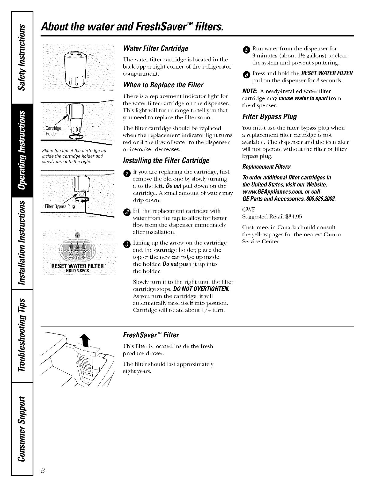
Aboutthe water andFreshSaverTM filters.
Place the top of the cartridge up
inside the cartridge holder and
slowly turn it to the right.
®
RESETWATERFILTER
HOLD3SECS
Water Filter Cartridge
l_he water filter cartridge is located in the
back Itpper right corner of tile reflJgei'ator
co///l)a I'tlllent.
When to Replace the Filter
Yhere is a l'el)lacelnent indicator light fin"
the water filter cartridge on tile disl)enser.
]_his light will turn orange to tell you that
w)u need to l'eplace the filter soon.
]_he filter cartridge should be replaced
when the replacement indicator light tt/rns
red or if the flow of water to the dispenser
or Joel[laker decreases.
Installing the Filter Cartridge
0 If _ou are re _lacino tile cartridge, ti_t
remoxe tile old one b) slowl) tm'ning
it to tile letL Donot pull down on tile
camidge. A small alllOtlnt of water may
drip down.
_Fill tile replacement cartridge with
water from tile tap to allow fi)r better
flow from tile dispenser immediately
atier installation.
Lining up tile arrow on tile cartridge
@
and the cartridge holder; place the
top of tile new cartridge up inside
tile holdex: Oo not push it up into
the holdex:
O P.tm water fl'om tile dispenser for
3 mimltes (about 1½ gallons) to clear
tile system and prevent sputtering.
0 Press and hold tile RESETWATERFILTER
pad on tile dispenser for 3 seconds.
NOTE: A newly-installed water filter
cartridge may cause water to spurt ti'om
the dispenser.
Filter Bypass Plug
x_u must use tile filter b)pass plug when
a replacement filter cartridge is not
available. Tile dispenser and tile icemaker
will not operate without tile filter or filter
bypass plug.
Replacement Filters:
To order additional filter cartridgesin
the United States, visit our Website,
www.GEAppliances.com,or call
GE Parts and Accessories, 800.626.2002.
(;X,_F
Suggested Retail ,$34.95
Customers in Canada should consult
tile _ellow pages tot tile nearest Camco
Serxice Center:
Slowly mrn it to tile fight tmtil tile filter
camidge stops. DO NOTOVERTIGHTEN.
_s you mrn tile cartridge, it will
atm)matically raise itself into position.
Cartridge will rotate about 1/4 ttlrn.
FreshSaver TM Filter
This filter is located inside tile fresh
l)ro(hlce (lrawei i
Tile filter should last approximately
eight yeats.
8

Abouttheshelvesandbins. www.GEAppliances.com
Not all features are on all models.
Refrigerator Door Bins and Freezer Door Tilt-Out Bins
Refrigerator bin
Freezer tilt-out bin
LargeBins
The larger reti_igerator door bins and
fl'eezer tilt-out door bins are ac!iustable.
To remove: i]fi the fl'ont of the bin straight
up, then lift up and out.
Toreplaceorrelocate:Engage the back side
of the bin in the molded supports oI the
do(n; Then push down on the fl'ont of the
bin. Bin will lock in place.
SmallBins
To remove: I,ifl the ti'ont of the bin strai,,ht
up then out.
To replace: Position the bin aboxe the
rectangular molded supports on the dora;
Then slide the bin down onto the support
to lock it in place,
The snugger helps prevent tipping, spilling
or sliding of small items stored on the door
shelf, Place a finger on either side oI the
snugger near the rear and move it back
and fl)rth to fit your needs.

Abouttheshelvesandbins.
Not all features are on all models.
Slide-Out Spillproof Shelf
The slide-out spillproof shelf allo_s you to
reach items stored behind othe_. The
si)ecial edges, are designed, to helli ) )re',ent
spills fl'om dripping to lower shelxes.
Toremove:
Press tab and pull shelf
forward toremove
Slide the shelf out until it reaches the stop,
then press down on the tab and slide the
shelf straight out.
Toreplaceorrelocate:
I,ine the shelf up with the suI)ports and
slide it into place. The shelf can be
reposifioned when the door is at 90 ° or
more. To reposifion the shelf, slide the shelf
past the stops and angle downward. Slide
shelf down to the desired position, line up
with the supports and slide into place.
Makesureyoupushtheshelvesa// the wayback
in beforeyoudose thedoor
QuickSpace TM Shelf
This shelf splits in half and slides under
itself fin" storage (ff tall items on the shelf
below.
This shelf can be removed and replaced
or relocated just like Slide-Out Spillproof
Shelves.
Freezer Baskets
Toremove, push the basket all the way to the
back of the fl'eezer i,ifi up until the back
pins are disengaged, i,ifi the entire basket
up and pull out.
Slide-Out Freezer Shelves
To remove, slide out to the stop position,
lift the ti'ont past the stop position, and
slide out.
On some models, this shelf can not be used
in the lowest position.
Makesureyoupushthebasketsall thewayback
in beforeyouclosethedoor
Makesureyoupushtheshelvesall the wayback
in beforeyouclosethedoor
) Fixed Freezer Shelves
Toremove,lift the shelf ul) at the left side
and then bring the shelf out.
/0

Abouttheadditionalfeatures, vvww.GEAppliances.com
Not all features are on all models.
Removable Beverage Rack
The beverage rack is designed to hold
a bottle on its side. It can be attnched to
any slide-out shelfi
i
Toinstall'.
0 IJne up the large part ot the slots on
the top of the rack with the tabs trader
the shelf,
Then slide the rack back to lock it
in place.
Aboutthe refrigeratordoors.
Refrigerator Doors
The refl_igerator doo_ may teel difli_rent
than the ones you are used to. The special
door opening/closing teattli'e illakes Stli'e
the (loo_ close all the way and are securely
sealed.
When opening and closing the door you
will notice a stop position, If the door is
opened past this stop point, the door will
remain open to allow you to load and
tmload toed nlore easily: When the door
is only partially open it will automatically
close.
When the door is only partially open
it will automatically close.
Beyond this stop the door will
stay open.
The resist;race you teel at the stop
position will be reduced as the door
is loaded with fi_od.
//

Aboutthe crispersandpans.
Not all features are on all models.
Fru# and Vegetable Crispers
Excess water that may accumulate in the
bottom of the (h'awe_ should be wiped dry.
On some models the bottom drawer has
a cover that slides back as the drawer is
opened. This allo_:s flfll access to the
drawex: _&sthe drawer is closed, the cover
!!_i_
will slide torward into its original position.
HI _ LO
0
Adjustable Humidity Crispers
Slide the control all the _'_' to the HIsetting
to provide high humidity recommended fin.
most vegetables.
Convertible Meat Pan
The convertible meat pan has its own cold
air duct to allow a stream ot cold air fl'om
the ti'eezer compartment to flow to the pan.
The variable temperature control regulates
the air flow fl'om the Climate Keeper:
Aboutcrisperremoval
Slide the control all the way to the LO
,settino,_to pro_i(le lower humidit) le_ els
recommended fin" most fl'uits.
Set the control to the coldestsetting to
store fresh IIle_lts.
Set the control to coldto convert the pan
to nomml refiigerator temperature and
provide extra vegetable storage space. The
cold air duct is turned off. Variable settings
between these extremes can be selected.
Not all features are on all models.
Crisper Removal
Crispe_ can easily be removed by pulling
the drawer straight out and lifting the
drawer up and over the stop location.
/2
If the door prevents you fl'om tnking out
the (h'awe_, ti_t t_y to remove the door
bins. ]f this does not offer enough
clearance, the refligerator will need to
be rolled ti)rward tmtil the door opens
enough to slide the (lrawexs out. ]n some
cases, when you roll the refligerator out,
p)u will need to move the refrigerator
to the left or right as you roll it out.

Aboutthe automaticicemaker, vvww.GEAppliauces.com
A newly-installed refrigerator may take 12to 24 hours to begin making ice.
%WeT Automatic Icemaker
_wimr
Greel
Power
ught
Pull the upper freezer shelf straight
out to access the icemaker. Always
besure to replace the shell The
shelf can be used for storage.
Eel TaKer
The icelnaker will produce seven cubes
per cycle'--aI)proxinmtely 100-130 cubes
in a 94-hour i)eriod, dei)ending on fl'eezer
COillpai'tlllent teillpei'attli'e_ i'OOill
temperature, imlnber of door openings
and other use conditions.
If tile refl_igerator is operated befi)re tile
water cotmecfion is tnade to the icetnaker,
set tile power switch in tile 0 (Off)position.
When the reti-igerator has been comlected
to tile water sui)ply, set tile power switch to
the I (ou) position.
The icemaker will fill with water when it
cools to 15°F (-10°C). A newlpinstalled
refl_igelator inay take 12 to 24 l/o/u_ to begdn
nlaking ice cubes.
Throw away tile first few batches of ice to
allow the wamr line to clea_:
Be sm'e nothing interteres with tile sweep
of the teeler amL
When tile bin fills to tile level ot tile feeler
amL tile icemaker will stop producing
ice. It is nomml for several cubes to be
joined togethei:
If ice is not used fl'equenfl}; old ice cubes
will become cloudy, taste st;lie and shlJnk.
If ice cubes get stuck in the icelnakei; the
green power light will blink. To correct this,
set the power switch to 0 (off) and relnove
tile cubes. Set tile power switch to I (on} to
restart the icemake_: _Mter the icemaker has
been turned on again, there will be a delay
of about 45 ininutes beloi'e tile icenlaker
i'estlilles opei'ation.
NOTE."Inhomeswithlower-than-averagewater
pressure,youmayheartheicemakercyclemu/t))/e
times when making one batch of ice.
i/
Ice Storage Drawer
To access ice, pull tile drawer for_m'(l.
To removethedrawer,pull it straight ()/it and
lift it past tile stop location.
il
73
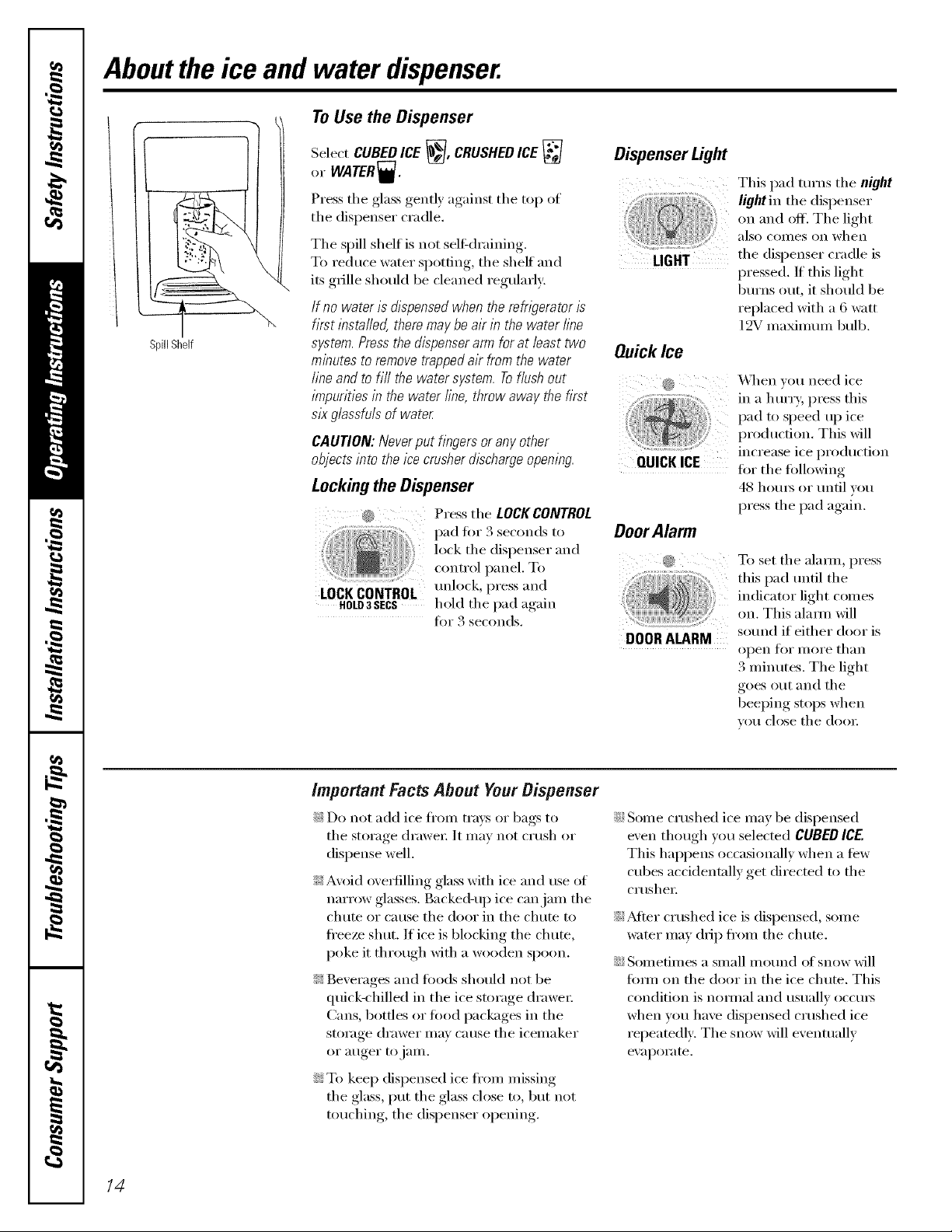
Aboutthe ice and water dispenser.
ToUsetheDispenser
SpillShelf
Select CUBED ICE _, CRUSHEDICE
or WATER_.
Press the glass gently against the top of
the dispenser cradle.
Tile spill shelf is not sel6draining.
To reduce water spotting, tile shelf and
its grille should be cleaned regularly:
If no water is dispensed when the refrigerator is
first installed, there may be air in the water line
system. Pressthe dispenser arm for at least two
minutes to remove trapped air from the water
line and to fill the water system. Toflush out
impurities in the water line, throw away the first
six glassfuls of water
CAUTION: Never put fingers or any other
objects into the ice crusher discharge opening.
Lockingthe Dispenser
@ Press tile LOCKCONTROL
lock tile dispenser and
control panel. To
h.ld''l'c 'theP"essl) ,d
fi:,r 3 seconds.
Dispenser Light
This pad turns the night
light in the dispenser
on and off. The light
also COilleS on when
tile dispenser cradle is
pressed. If this light
burns out, it should be
replaced with a 6 watt
12V maximmn bulb.
QuickIce
..............................................\,\lien wm need ice
in a hmTy, press this
pad to speed up ice
production. This will
increase ice production
QUICKICE ti)r tile tblhm'ing
48 hom_ or tmtil you
I)ress tile pad again.
DoorAlarm
......................................................To set the alamo, press
this pad tmtil tile
indicator light comes
on. This alama will
DOOR ALARM sound if either door is
open ti)r more than
3 minutes. The light
goes out and the
beeping stops when
VO/I close tile dooI:
14
important Facts About Your Dispenser
i_;:Do not add ice ti'om trm:s (:,rbags to
the storage drawer It may not crash or
dispense well.
;i::Avoid eye,tilling glass with ice and use of
narrow glasses. Backed-up ice can jam the
chute or cause tile door in tile chute to
freeze shut. If ice is blocking the chute,
poke it through with a wooden spoon.
_i::Beverages and foods should not be
quick-chilled in the ice storage drawer:
Cans, bottles or food packages in tile
storage drawer may cause the icemaker
or auger to jaIn.
N To kee I) dispensed ice ti'om missing
the glass, put the glass close to, but not
touching, the dispenser opening.
i_i;:Some crushed ice may be dispensed
even though you selected CUBED ICE
This hapi)ens occasionally when a ti_w
cubes accidentnlly get directed to the
cI'tlsheI:
Yi;_Mier crushed ice is dispensed, some
water may drip from the chute.
i_;:Sometimes a small m om_d (ff snow will
timn on the door in the ice chute. This
condition is nomml and usually occurs
when you have dispensed crushed ice
repeatedly: The snow will eventually
eV_ll)OI';lte.
Careand cleaning of therefrigerator.
Behind the Refrigerator
Be caretul when moving the refl_igerator
away fl'om the wall. MI t)pes ot floor
coverings can be dalnaged, particularly
cushioned coverings and those with
eillbossed S/li'J[ilces.
Pull the refl_igerator straight out and return
it m position by pushing it straight in.
Moving the reti_igerator in a side direction
may result in damage to the floor covering
or reti_igerato_:
Preparing for Vacation
For long \;l('ations or absences, rell/ove
food and uI_plug the reli_igei'ato_: Clean the
interior with a baking soda solution of one
tablespoon (l 5 ml) of baking soda to one
quart (l liter) of water; i,eave the (loo_
open,
Set the icemaker power switch to the 0 (off}
position and shut off the water supply to
the refrigerator;
Whenpushingtherefngeratorback,makesure
youdon't rofl overthepowercordoricemaker
supplyline.
If the temperature can drop below
fl'eezing, have a qualified servicer drain the
water supply systeln to prevent serious
prope_ F damage due to flooding.
Preparing to Move
Secure all loose items such as shelves and
drawe_ by taping them secm'ely in place
to prevent damage.
XA]mn using a hand truck to move the
reti_igerator, do not rest the fl'ont or back of
the refrigerator against the hand truck.
This could damage the refrigerator: Handle
only from the sides of the refrigerator:
Be sure the refngerator stavs /b an upnght
position during moving.
/6
Replacingthelightbulbs, vvww.GEAppliances.com
Setting the controls to OFFdoes not remove power to the light circuit.
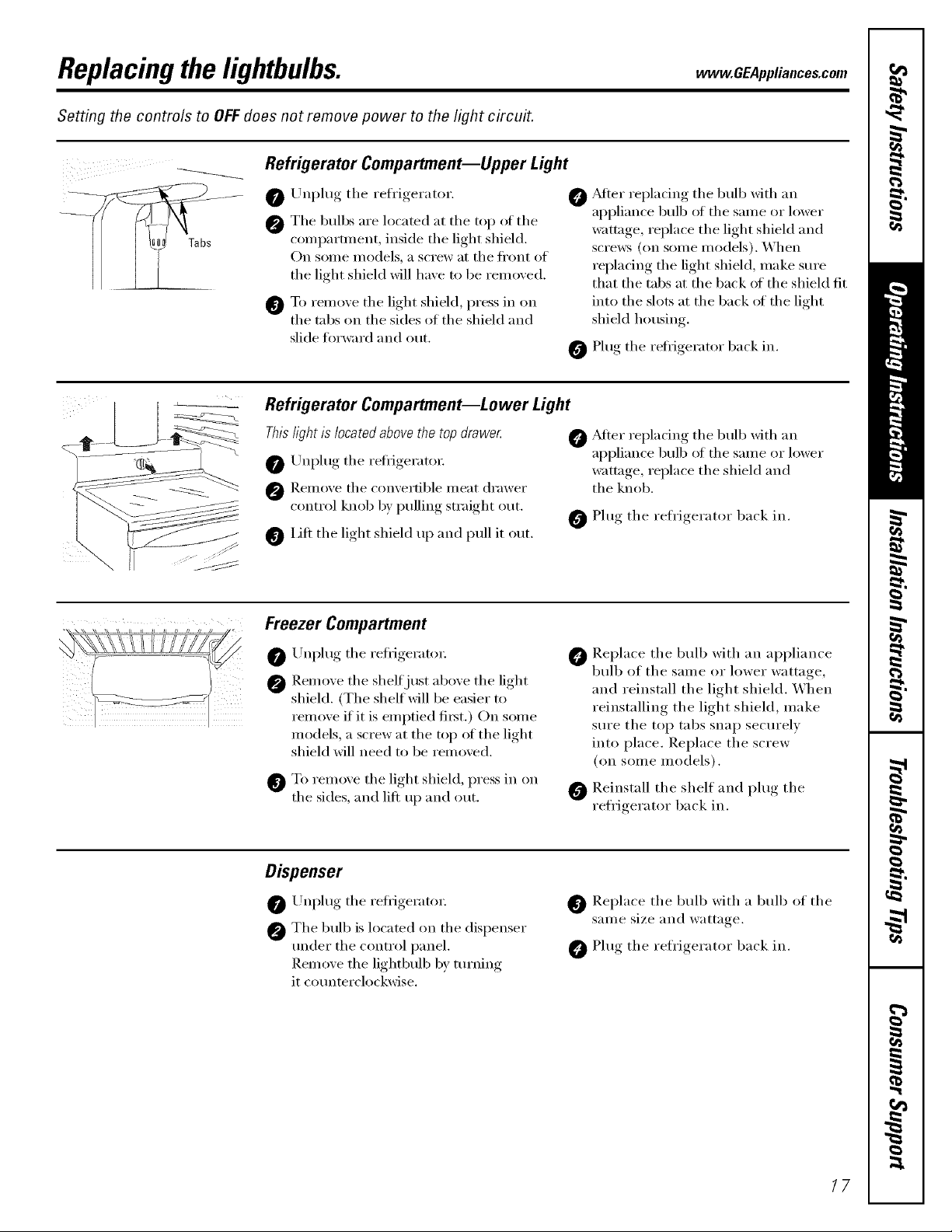
Refrigerator Compartment--Upper Light
Unplug the refl'igerator.
0
The bulbs are located at the top of the
@
comparm_ent, inside the light shield.
On some models, a screw at the front of
the light shield will have m be removed.
To remoxe the light shield, press in on
@
the tabs on the sides of the shield and
slide fin'ward and o/It.
Refrigerator Compartment--Lower Light
This light is located above the top drawe_
O Unplug the reflJgerato_:
@ ]_.elnove the convertible ineat drawer
control knob by pulling straight out.
i]fi the light shield up and pull it out.
Freezer Compartment
O ,Mter replacing the bulb with an
appliance bulb ot the same or lower
wattage, replace the light shield and
scrmvs (on some models). When
replacing the light shield, make sure
that the tabs at the back of the shield fit
into the slots at the back ot the light
shield housing.
Plug the refl{gerator back in.
@ .Mter rei)lacing, the bulb with an
appliance bulb of the same or lower
wattage, replace the shield and
the knob.
0 Plug the refrigerator back in.
Unplug the reflJgeratoi:
Remove the shelf just above the light
shield. (The shelf will be easier to
remove if it is emptied fi_t.) On some
models, a screw at the top of the light
shield will need to be removed.
O To remove the light shield, press in on
the sides, and lift up and out.
Dispenser
Unplug the reflJgeratoi:
@ The bulb is located on the dispenser
under the control panel.
Remoxe the lightbulb by turning
it counterclockwise.
P,eplace the bulb with an appliance
bulb of the same or lower wattage,
and reinstall the light shield. When
reinstalling the light shield, make
sure the top tabs snap securely
into place. Replace the screw
(on some Inodels).
O P,einstall the shelf and plug the
reflJgerator back in.
Replace the bulb with a bulb of the
Sallle size and wattaoe
O Plug the refrigerator back in.
17

Trimkits anddecoratorpanels.
For CustomSly/eTM models
Read theseinstructions completely and carefully.
BeforeYouBegin
Some models are equipped with trim kits that aflow you to instafl door panels. You can order pre-cut
black, white, almond, bisque, or stainless steel decorator panels from GEParts and Accessories,
800.626.2002,or you can add wood panels to match your kitchen cabinets.
Panels less than 1/4" (6 mm) thick
When installing wood panels less than l/4" (6 ram) thick, you need to create a filler panel, such as l/8"
cardboard, that will fit between the fi_ce of the door and the wood panel. If you are installing the l)re-cut
decorator panels, pre-cut filler panels are included in the kit. The combined thickness of the decorator or
wood panel and the filler panel should be 1/4" (6 ram).
Panels1/4"thick oriess
1/4" max
3/4" (19 mm) or Raised Panel
A raised panel design screwed or glued to a l/4" (6 ram) thick backing, or a 3/4" (l 9 ram) routed board
can be used. The raised portion of the l)anel must be tid)ficated to l)e_nit clearances of at least 2" (5.1 cm)
fl'om the handle side fin" fingertip clearance.
Panels thicker than 1/4" (6ram), up to 3/4" (19 ram) max, will require that the outer 5/16" (8 ram) of
panel perimeter be no thicker than 1/4" (6 ram).
Weightlimitationsfor custompanels:
FreshFood38Ibs. (17kg)max.
FreezerDoor28Ihs.(13kg)max.
Panelsthickerthan1/4" (6mm)
2"(5.1 cm) II llll __---"-...._",-_
1/4"(6mm)
ThickBacking
Ol_aranc_I IIIII _"
3/4"(19mm) pApp:_ra,,ceqi111 • ,or
Door
18
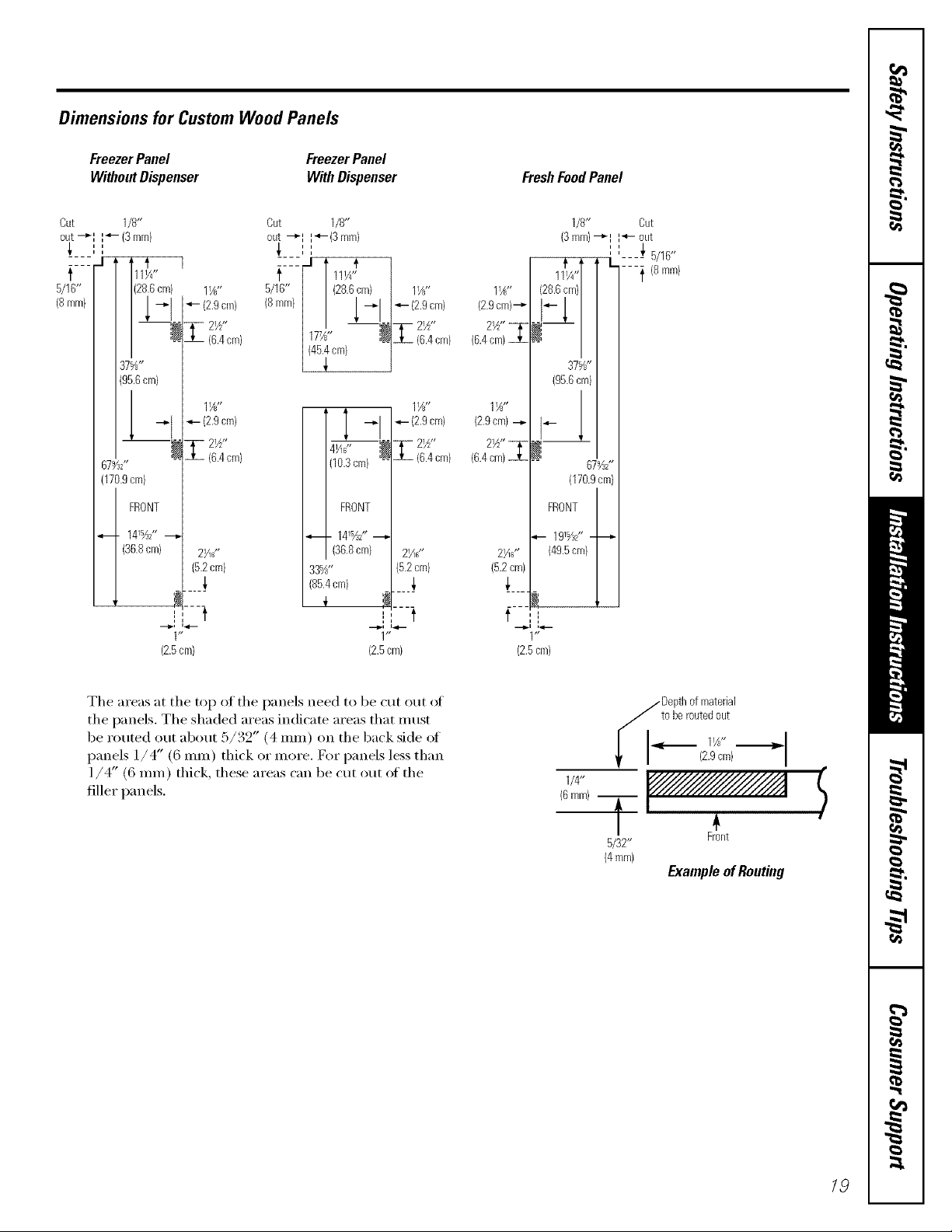
Dimensions for Custom Wood Panels
FreezerPanel
WithoutDispenser
Cut 1/8"
out-_I I_- (3mm)
i i
t
5/16"
(8mm}
37%"
(95.6cm)
67%Z
(170.9cm)
FRONT
_. 141%2" _
(36.8cm) 2¼s"
Out 1/8"
out -_I I_'-(3 mm)
_, ,,
cm) 1Y?"
7_- 21/2"
iX_I -I290m>
-"I 4- (2.9cm)
(6.4cm)
11A,,
(6.4cm)
(5.2cm)
5/_6 [ 111A"
.... -I I #
< mm>/
FreezerPanel
With Dispenser
i i
" (28.6cm)
_- {2.9cm)
177_" l_
(45.4ore)
T -'29cm>
,, _ T- 2½"
(10.3cm) -- Jh (6.4cm)
Z2_"
16.4cm)
11_"
1(36.8 cm) 2>_"
33%" (5.2cm)
(85.4cm) _,
11_"
(2.9cm)--_
2W' _
(6.4cm)
1½"
(2.9cm) --i-
2W' _
(6.4cm)
2Hs"
(5.2cm)
FreshFoodPanel
1/8" Cut
(3mm)--_I I"4- out
11'_1/4,,l /---'_ {8 nlm}
(28.6cm)/
#x/
° /
37%"
(95.6cm)
#1
(170.9cm)
FRONT
-_-- 19%Z'----_
(49.5cm)
!,
,, _,
' '---- 5/16'*
67%2'*
I, t
1"
(2.5cm}
The areas at the top of the panels need to be cut ()tit ot
the panels. The shaded areas indicate areas that must
be muted otlt about 5/39" (4 ram) on the back side ot
panels 1/4" (6 ram) thick o_"more. For panels less than
1/4" (6 ram) thick, these a_'eas can be cut out of the
fille_" panels.
i t
1"
(2.5cm)
f ,',
(2.5cm)
i_1 Depthofmaterial
toberoutedout
i I (2.9cm)
114"
(6ram)T _<
5/32"
(4mm)
Front
ExampleofRouting
$
19

Insertingthe doorpanels.
Read these instructions completely and carefully.
0 Loosenthe TopTrim onthe Freezer and FreshFood Doors.
Using a T-20 Torx ddxet; loosen the two screws
attaching the Top Trim about 1/4" (6 ram).
Insert the Freezer Panel and Fresh Food Panel
O
I,ifl the Top Trim up 1/4" (6 ram) and carefldlv
push the ti'eezer panel in tmtil it slides into the slot
behind the door handle. Push the filler panel
(required with some door panels) in behind the
decorau)r panel. Repeat fl)r fl'esh ti)od panel.
0 Insert the Bottom Panel.
(_arefully push the panel in tmtil it slides into the
slot behind the door handle. Push the filler panel
(required with some door panels) in behind the
decorator panel.
If your model has a dispenser and/or a
Refreshment Centex; this step onl) applies
to the top panels.
Hand tighten the two screws on the Top Trim.
Cut-Out
SideTrim
20

0 Install the Side Trim.
These pieces are rocked inside the refi_igerator
door handle.
Donot removetheproacfive film on theouaide of
theSideTrimuntil theSideTnmis installe_
Fit the botton_ oI the Side Trim under the
gottom Trhn as illustrated.
Hold the Side Trim against the fl'ont ti_ce (ff the
decorator panels and fit the Side Trim under
the Top Trim, Make sure the Side Trim is fitted
correctly and that you are satisfied with the
appearance of all the parts before pulling the
tape line_:
O Secure the Side Trim.
Place one hand between the two pieces of tape
liner and hold the Skle Trim firefly against the
panels and the side of the doo_,
Pull the mp tape liner up about 3" (80 ram),
pressing the triln with your hand as the adhesive
is exposed to the dooi: Then pull the bottom
tape liner down about 3" (80 inln). Follow the
tape with your hand, pressing the trim adhesive
against the doo_:
Continue pulling the tape liner loose, alternating
between the top and bottom and pressing the
Side Trim against the doo_:
0 Remove the Protective Film From the Outside of the Side Trim.
21

Installingand removingpreviouslyinstalled decoratorpanels.
Read these instructions completely and carefully.
Removing the Handles
In order to remove the decorator panels and replace
with new panels you need to remove the handles.
A 520 Torxdriver is neede_
I,oosen and reinove tile 2 sci'e_vs in tile
Top Trim.
O I,oosen and remove tile 2 scre_vs in tile
bracket that attaches tile Handle to tile
top of tile Doo_:
O (;rip tile Handle fired) and slide upwards,
The kexhole slots on the Handle slide off
tile bu[tons on tile door.
0 Open tile door and slide out tile decorator
panels.
TopTrimScrews
BracketScrews
Bracket
>Slots
22
Inserting the Door Panels
Before installing the decorator panels, make sure they have been routed out in the proper areas as shown/n the
beginmng of this section. Slide in the panels to perform a toal fit before fastemng down the Hand& and TopTrim.
Installing the Handles
Oncethe pane& are fitted pmperly, install the Handle and Top Trim.
0 Slide tile ke)hole slots on tile Handle down
onto tile buttons mounted to tile fi_ce of tile
doo_: Slide the Handle dowmvard tmfil the
bracket at tile top ot tile Handle fits flush on
the top of the door.
Replace tile two scrm_:s in tile bracket that
attach tile Handle to the top of tile Door and
tighten tile scrm_:s to 45 in-lbs torque.
O Replace tile Top Trim making sure it fits over
the Side Trim and that the locating tabs fit the
inside of the Handle profile.
O Replace tile Top Trim screws and tighten to
30 in-lbs torque,
Removingandreplacing the doors.
When installing or moving the refrigerator, the doors may need to be removed in order to fit the refrigerator
through a doorway.
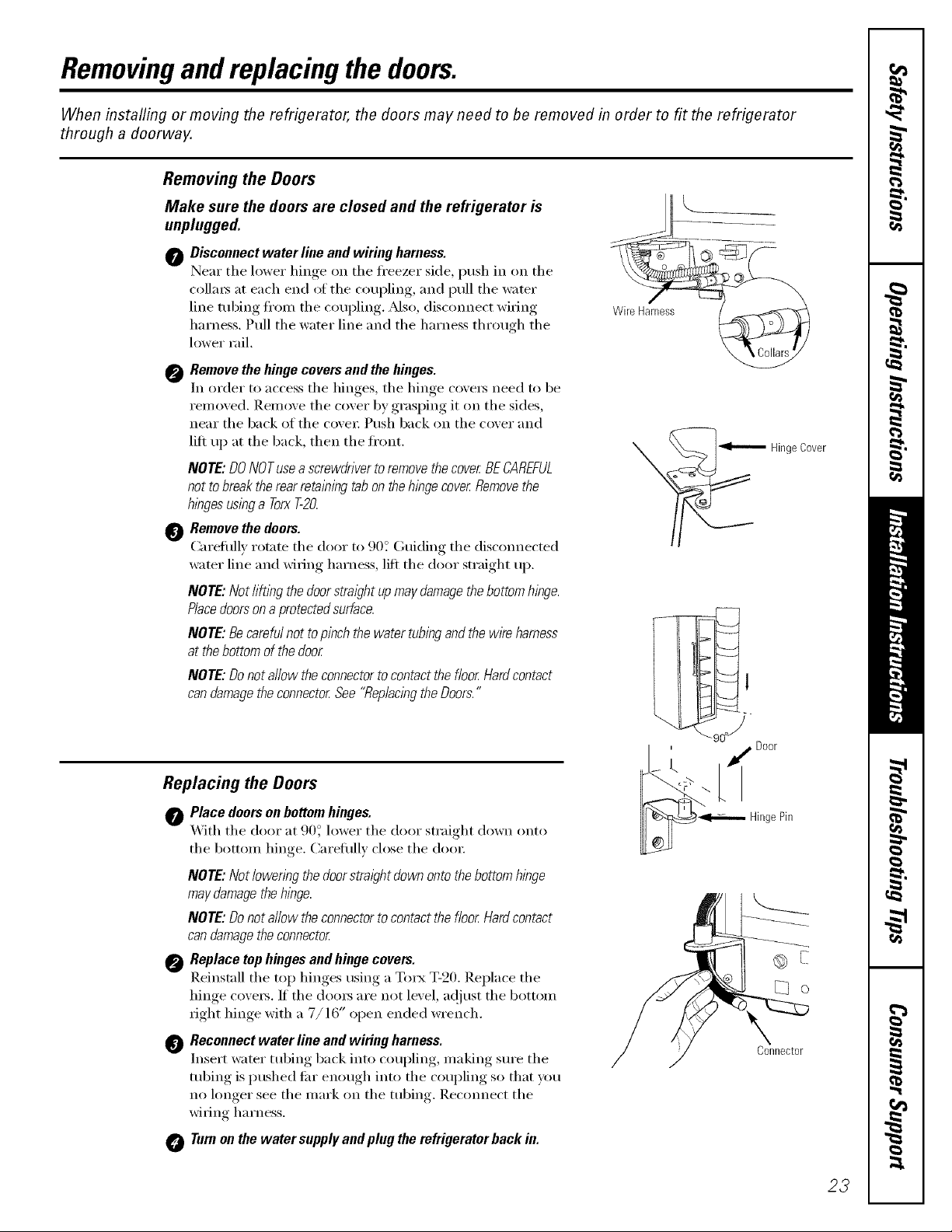
Removing the Doors
Make sure the doors are closed and the refrigerator is
unplugged.
0 Disconnect water line and wiring harness.
Near the lower hinoe_ on the fl'eezer side, push in on the
collm_ at each end ot the coupling, and pull the water
line robing fl'on/the coupling. _Mso, (liscmmect wiring
harness. Pull the water line and the harness through the
lower rail.
0 Remove the hinge covers and the hinges.
In order to access the hinges, the hinge ('ove_ need to be
removed. Remove the cover by grasping it on the sides,
near the back of the covei: Push back on the cover and
lift up at the back, then the front.
/VOTE:DONOTusea screwdriverto remove the cover BECAREFUL
not tobreak the rear retaining tabonthe hinge cover Removethe
hlbgesuslbga TorxT-20.
0 Remove the doors.
(:arefhllv rotate the door to 90? (;uiding the disconnected
water line and wiring harness, lift the door straight up.
NOTE: Not li@bg the doorstraight upmaydamagethebottom hinge.
Piecedoorsona protectedsurface.
/VOTE:Becareful not topinch thewater tubingand thewire harness
at thebottom of the door
/VOTE:Donot allow theconnectorto contact the floor Hardcontact
can damagetheconnector See "Replacingthe Doors."
WireHarness%
-- HingeCover
Replacing the Doors
0 Place doors on bottomhinges.
X'_ith the door at 9(F lower the door straight down onto
the bottom hinge. Careflflly close the do(n:
/VOTE:Not lowenbg thedoorstraight down onto thebottom hinge
may damagethe hlbge.
/VOTE:Donot allow the connectorto contact thefloor Hardcontact
can damagetheconnector
0 Replace top hinges and hinge covers.
Reinstall the top hinges using a Torx T-20. Replace the
hinge cove_. If the dom_ are not level, a@_st the bottom
right hinge with a 7/16" open ended wrench.
_) Reconnect water line and wiring harness.
Insert water tubing back into coupling, making sure the
tubing is pushed liar enough into the coupling so that you
no longer see the mark on the robing. Recmmect the
wiring harness.
0 Turnon the water supplyand plug the refrigerator hack in.
I ' _ Door
_ HingePin
Connector
23
Installation
Refrigerator
Instructions
Models 21,23, 25,27 & 29
Questions?Call800.GE.CARES(800.432.2737)or visit ,,,uX_ebsite,t: www.GEAppliances.comIn Canada,call 1.800.361.3400orvisitour _ebsite at: www.geappliances.ca
BEFORE YOU BEGIN
Read these instructions completely and carefully.
• IMPORTANT - S.ve hese
instructions fin" local inspector's use.
•IMPORTANT - Obse,,e:,11
go\ erning codes and ordinances.
• Note to Installer _ Besure to leave these
instructions with tile Consumer.
• Note to Consumer _ KeeI)these instructions
f()r hlttu'e retbrence.
CLEARANCES
_Mlow tile following clearances fin" ease of installation,
i)roper air circulation and I)hunbiI_g, and electrical
colnlectiollS:
21' mad 23' 25', 27', mad 29'
• Sides 1/8" (4 ram) 1/8" (4 ram)
• Top 1" (25 ram) 1" (25 ram)
• Back 1/2" (13 ram) 1" (25 ram)
ROLLERS
• SMll level - Installation of this appliance requires
basic mechanical skills.
• Completion time - Refi'igerator Installation
15 minutes
• Proper installation is tile responsibility of tile
installer.
• Product fhilure due to improl)er installation is not
covered under tile _u'ranty.
WATER SUPPLY TO THE ICEMAKER
(ON SOME MODELS)
The rollers have 3 purposes:
• RolleI_ a_!just so tile door closes easily when opened
about hallway: [Raise tile fl'ont about 5/8" (l 6 mill) fl'oln
tile flooI:]
Rollei5 a(!just so tile reii_igerator is firefly positioned on
tile floor and does not wobble.
• Rollels alh m' wm to In_)ve tile refrigerator away fl'om tile
wall tot cleaning.
Final leveling a(!justments should be inade after tile
refrigerator has been installed.
I
If tile reli'igerator has an icemaker, it will have to be
connected to a cold water line. AGE water sui)ply kit
(containing tubing, shutoff wflve, fittings and
iI_structions) is available at extra cost fl'oln your dealer,
by visiting our X,Vebsite at www.Gl?_ppliances.com (in
Canada at www.geappliances.ca) or froln Parts and
Accessories, 800.626.2002 (in Canada 1.888.261.3055).
REFRIGERATOR LOCATION
• Do not install tile refiJgerator where tile teml)erature
will go below 60°F (l 6°C) because it will not run ol_tell
enough to maintain l)roper teml)eratures.
• Do not install tile refrigerator where tile teml)erature
will go above 100°F (37°(;) because it will not pei_fimn
properly.
• Install it on a floor strong enough to suI)port it hilly
loaded.
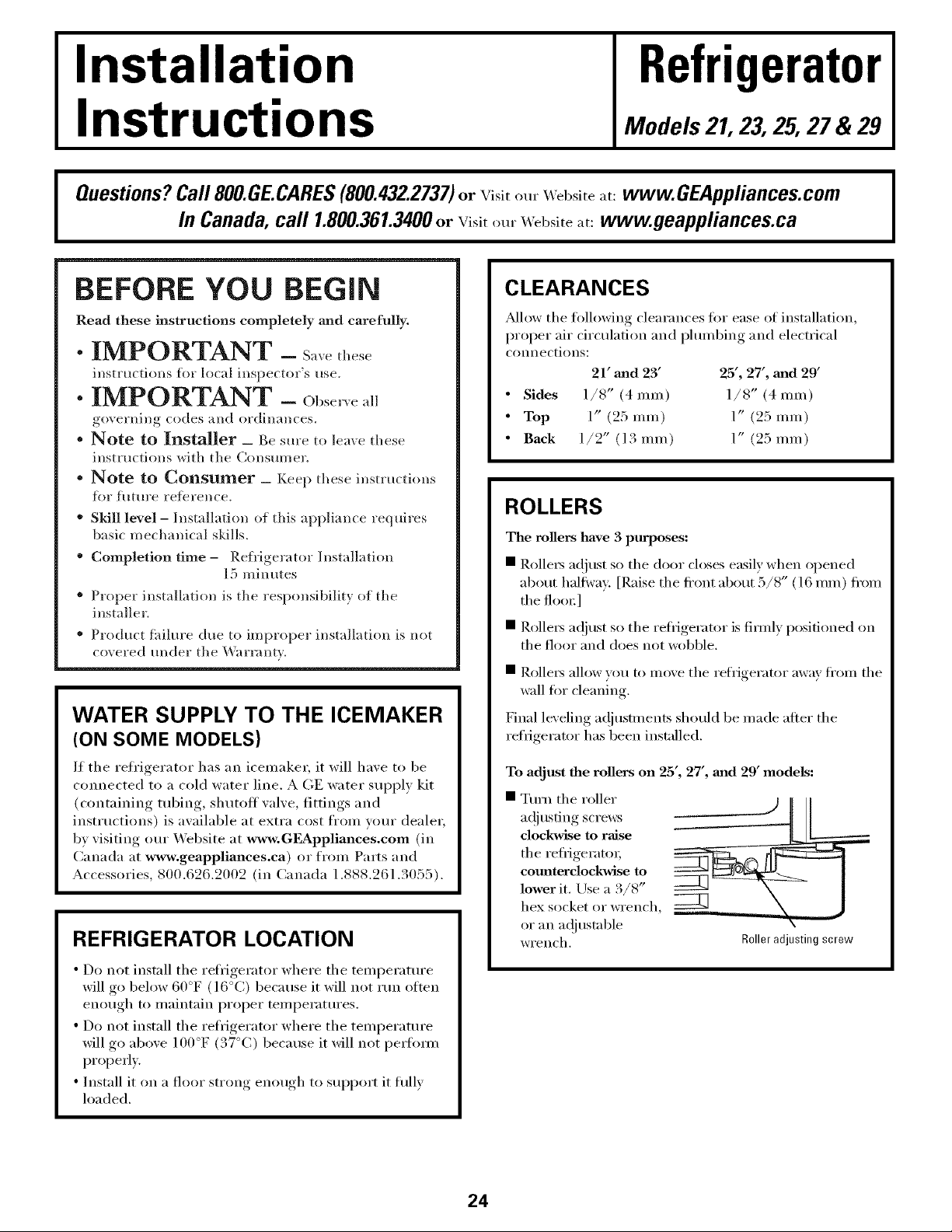
To adjust the rollers on 25', 27', mad 29' models:
Ttu'n tile roller
adjustin,, screws
clockwise to raise
tile refrigeratoL
comaterclockwise to
lower it. Lrse a 3/8"
hex socket or wreIlch,
or }111 ac{justable
wreIlch.
24
[_____
k
Roller adjusting screw

Installation Instructions
ROLLERS {CONT.)
To adjust the rogers on 21' and 23' models:
O Remove tile base grille by opening tile doo_,
removing the screws at each end, and pulling it
straight out.
O Turn the fl'ont roller
adjustino screws
dockwise to raise
the refi_igerato_;
eomaterdockwise to
lower it. Use a 3/8"
hex socket or wrench,
or an adjustable
wrench. Roller adjustingscrews
These models also have rear a(!justable rollers so you
can align the refiigerator with your kitchen cabinets.
Use a long-handled 5/16" socket wrench to turn tile
scre_vs tot tile rear rolle_loek,Mse to raise tile
refligerato_; comlterelock_dse to lower it.
O Replace tile base grille.
DIMENSIONS AND SPECIFICATIONS
(for CustomStyle TM models}
o o
..... .....
70¼"(178.4cm)
o
o
" 36"_
(91.4cm}
.......................................24" (61fm}_.................
Water Electrical
DOOR ALIGNMENT
_M[er leveling, make sm'e that doors are even at tile top.
To maim the doors even, a(!iust tile refiigerator door.
Using a 7/16" socket _,_rench, ttWll the door ac{}usting
screw to the fight to raise tile doo_; to tile left to lo,_er
it. (A nylon plug, imbedded ill tile threads oi the pin,
prevents tile pin fl'om turning unless a wrench is used.)
O _[el" ()lie o1" two [tWllS ()]_ tile _l'ench, ()})ell _|lld close
tile refligerator door and check tile aligmnent at tile
top (ff tile dool_.
Toremovethe basegrille,
openthedoors,remove
tbescrewateacbendof
thebasegrilleandthen
pallthegrille straighteat.
7/I6"SocketWrench]
/4" (19ram)Airspace
(1/2"[13mm]Gap+
24" (61cm) 1/4" [6mm]WallPlates) 1.5cm}
Cabinet Couotertop
' 2C 1
Raise
25

Installation Instructions
iNSTALLiNG THE WATER LiNE IoNSOMEMODELS)
BEFORE YOU BEGIN
Recommended COl)per water supply kits are _,\_XSX2,
_._X8X3 or _._?X8X4, depending on the amom_t of tubing
vou need. Approved plastic water SUl_ply lines are GE
Smarteonnect TM Reli'igerator Tubing (WX08X10002,
_._TX08X10006, _._TX08X10015 and WX08X10025).
When com_ecting yore" refiJgerator to a GE ReveI_e
Osmosis Water System, the only approved installation is
with a GE RVt(it. For other reverse osmosis water systems,
follow the inanttfilcturer's recolmnendations.
If the water sui)ply to the reti'igerator is from a Reverse
Osmosis X,Vater Filtration System AND the refrigerator
also has a water filteI; use the reti'igerator's filter bypass
plug. Using the reli'igerator's water filtration cartridge
in conjm_ction with the RO filter can result in hollow
ice cubes and slower water flow fl'om the water
dispenser.
This water line installation is not warranted bv the
refrigerator or icemaker manufi_cturer. Follow these
instructions carefifllv to minimize the risk of expensive
water damage.
Water hammer (water banging in tile pipes) in house
plmnbing can cause damage to refrigerator parts and
lead to water leakage or flooding. Call a qualified
plmnber to correct water hammer before installing the
water sui)ply line to the refl'igerator.
To prevent bm'ns and product damage, do not hook
up the water line to the hot water line.
If wm use your refrigerator beii)re connecting the
water line, make sure the icemaker power switch is in
tile 0 (off} position.
Do not install the icemaker tubing in areas where
temperatures fall below freezing.
When using any electrical device (such as a power
drill) dm'ing installation, be sm'e the device is doul)le
insulated or grounded in a manner to prevent the
hazard of electric shock, or is battery powered.
All installations must be in accordance with local
i)hunbing code requirelnents.
WHAT YOU WILL NEED
J
• Copper or GE SmaJctCommct TM Refrigerator Tubing
kit, 1/4" outer diameter to connect the refl'igerator
to the water sui)i)ly. If using copper, be sure both ends
of the tubing are cut square.
To detemline how much robing you need: measure
the distance ti'om the water valve on the back of the
reti'igerator to the water supply pipe. Then add 8'
(2.4 m). Be sm'e there is sufficient extra tubing (about
8' [2.4 m] coiled into 3 turns of about 10" [25 cnl]
diameter) to allow the refrigerator to move out fl'om
the wall after installation.
GE Slnart(_onnect TM Refl'igerator Tubing Kits are
awfilable in the fi)llowing lengths:
2' (.6 m) - WX08X10002
6' (1.8 m) - WX08X10006
15' (4.6 m) - WX08X10015
25' (7.6 m) - WX08X10025
Be sure that the kit wm select allows at least 8' (2.4 in)
as described above.
26

Installation Instructions
WHAT YOU WILL NEED (CONT.)
NOTE: The only GE approved plastic tubing is that
supplied in GE SmartCmmect TM Refrigerator Tubing
kits. Do not use may other plastic water supply line
because the line is under pressure at all times. Certain
types of plastic will crack or rupture with age and
cause water dmuage to your home.
• AGE water supply kit (containing tubing, shutoff
valve and fittings listed below) is available at extra
cost fi'om wmr dealer or ti'om Parts and Accessories,
800-626-2002 (in Canada 1.888.261.3055).
• A cold water supply, The water pressm'e must be
between 20 and 120 p.s.i. (1 A-8.1 bar),
• Power drill.
• 1/2" or adjustable wrench.
• Straight mid Phillips blade screwdriver.
Install the shutoff xalxe on the nearest frequentl) used
drinking water line.
[] SHUT OFF THE MAIN WATER
SUPPLY
Turn on the nearest faucet hmg enough to clear
the line of water.
[] CHOOSE THE VALVE LOCATION
Choose a location fi)r the valve that is easily
accessible. It is best to connect into the side of a
vertical water pipe. When it is necessary to connect
into a horizontal water pipe, make the connection
to the top or side, rather than at the bottom,
to avoid drawing ott anv sediment fl'om the
water pipe.
• Two 1/4" outer diameter compression nuts and
2 ferrules (sleeves)--to connect the copper tubing
to the shutoff wdve and the refl'igerator water
wdve.
OR
• If vou are using a GE Sillart(]onnect TM Refl'igerator
Tubing kit, the necessai T fittings are preassembled to
the tubing
• If vom" existing COl)per water line has a flared fitting
at the end, you will need an adapter (awfilable at
I)lumbing SUl)ply stores) to connect the water line to
the refl'igerator OR you can cut off the flared fitting
with a tube cutter and then use a compression fitting.
Do not cut formed end from GE Su/arteonnect TM
Reti'igera tot tubing.
• Shutoff valve to connect to the cold water line.
The shutoff wdve should have a water inlet with a
minimum inside diameter of 5/32" at the point of
connection to the COLD WATER LINE. Saddle-type
shutoff wdves are included in many water sui)ply kits.
Before i)m'chasing, make sm'e a saddle-type wdve
complies with your local I)lumbing codes.
[] DRILL THE HOLE FOR THE VALVE
Drill a 1/4" hole in the water pipe (exert if usin,*._ a
sellZpiercing xalxe), using a sharp bit. Remoxe anx
bm'rs Iesultmg from drilling,, the hole in the pipe.
Take care not to allow water to drain into the drill,
Faihu'e to drill a 1/4" hole max result in reduced
ice production or smaller cubes.
27
Installation Instructions
INSTALLING THE WATER LINE (CONT.)
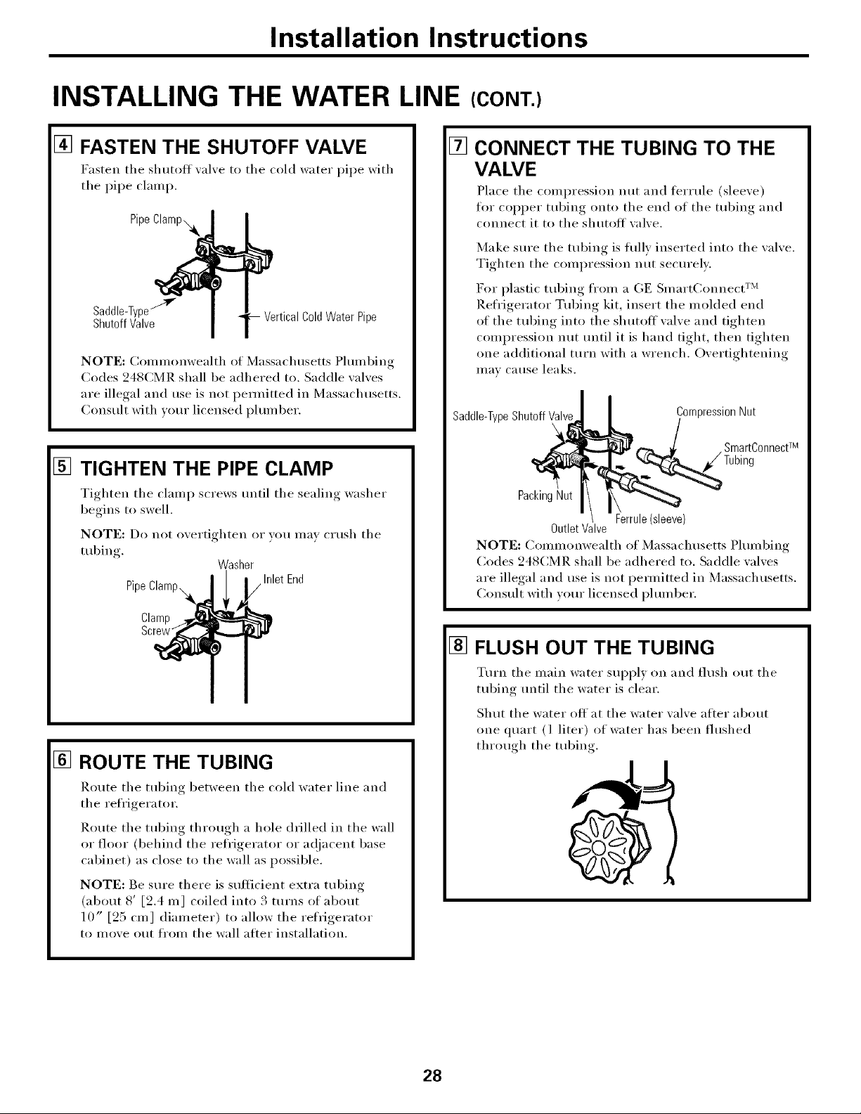
[] FASTEN THE SHUTOFF VALVE
Fasten tile shutoff _al_e to tile cold water pipe with
tile pipe clamp.
Pipe
Saddle-Type'"_ ColdWaterPipe
ShutoffValve
NOTE: Conm_onwealth of Massachusetts Plumbing
Codes 248CMR shall be adhered to. Saddle wflves
are illegal and use is not pemfitted in Massachusetts.
Consult with wmr licensed i)lmnber.
[] TIGHTEN THE PIPE CLAMP
Tighten tile clamp screws tmtil tile sealing washer
begins to swell.
NOTE: Do not overtighten or w)u may c_ush tile
tubing.
Pipe
Clamp
Screw_
Washer
Inlet End
r •
[]
CONNECT THE TUBING TO THE
VALVE
Place tile compression nut and teHule (sleeve)
for COl)per tubing onto tile end of tile tubing and
connect it to tile shutoff valve.
Make sm'e tile tubing is flflly inserted into tile valve.
Tighten the compression nut secm'elv,
For plastic tubing fl'om a GE Sn/art(_onnect TM
Refl'igerator Tubing kit, insert the molded end
of the tubing into the shutoff' wflve and tighten
compression nut until it is hand tight, then tighten
one additional turn with a wrench. Overtightening
Ill}IV CatlSe leaks.
I
Saddle-TypeShutoffValve I CompressionNut
SmartConnectTM
PackingNut
OutletValve
NOTE: (_onllnonwealth of Massachusetts Plulnbing
(:odes 248(:MR shall be adhered to. Saddle wflves
are illegal and use is not pemfitted in Massachusetts.
Consult with vom" licensed plmnber.
[] FLUSH OUT THE TUBING
Ferrule(sleeve)
[] ROUTE THE TUBING
]_.oute tile tubing between tile cold water line and
tile refl'igera tot.
Route tile tubing through a hole drilled in tile wall
or floor (behind tile refl'igerator or a(!jacent base
cabinet) as close to the wall as possible.
NOTE: Be sure there is sufficient extra tubing
(about 8' [2.4 m] coiled into 3 turns of about
10" [25 cm ] diameter) to allow tile refrigerator
to move out fi'om the wall atter installation.
Tm'n tile main water sui)ply on and flush ()lit tile
tubing until tile water is clear.
Shut tile water off at tile water valve alter about
one quart (l liter) of water has been flushed
through tile tubing.
28

Installation instructions
[] CONNECT THE TUBING TO THE
REFRIGERATOR
NOTES:
• Before making tile connection to tile refl'igerator,
be sure tile refl'igerator power
cord is not i)lugged into tile wall outlet.
• If your refl'igerator does not have a water filter,
we recommend installing one. If your water
sui)ply has sand or particles that could clog tile
screen of the reti'igerator's water valve. Install it in
tile water line near tile reli'igerator. If using (;E
SmartConnect Refl'igerator Tubing kit, you will
need an additional tube (WX08X10002) to
connect tile filter. Do not cut plastic tube to
install filter.
Some models have the refl'igerator connection at
the end of tubing located outside the compressor
COUll)ai'tulent access cover. On other models tile
COUll)I'eSSOI" cou/l)ai'tli/ent access cover UltlSt be
removed in order to access tile reti'igerator
connection at tile water valve.
[] CONNECT THE TUBING TO THE
REFRIGERATOR (CONT.)
Insert tile end of tile tubing into tile water valve
connection as tar as possible. While holding tile
tubing, tighten tile fitting.
For plastic tubing fl'om a GE SmartConnect TM
Refl'igerator Tubing kit, insert the molded end
of the tubing into the refl'igerator connection and
tighten the compression nut until it is hand tight,
then tighten one additional turn with a wrench.
Overtightening may cause leaks.
Fasten the tubing into the clamp provided to hold
it in a vertical position. You may need to I)_T open
tile clamp.
One of the illustrations below will look like the
connection on your refrigerator.
Tubing 1/4"
1/4"
Compression\
Nut
Ferrule
On models usin,* tile refrigeration connection at
the water xalxe, remoxe the plastic flexible cap.
Place tile compression nut and terrule (sleeve)
onto tile end of tile tubing as shown. On tile GE
SmartConnect TM Reii'igerator Tubing kit, the nuts
are ah'eady assembled to tile tubing.
SmartConnectw
Tubing
TubingClamp
1/4"
CompressionNut
Ferrule
(sleeve)
Refrigerator
Refrigerator
Connection
1/4"Tubing
SmartConnectTMTubing
29
installation instructions
INSTALLING THE WATER LINE (CONT.)
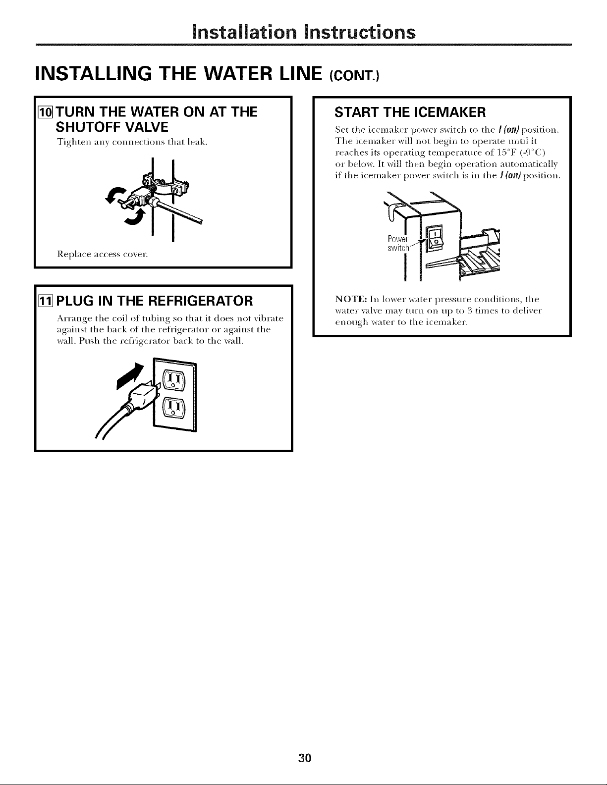
[] TURN THE WATER ON AT THE
SHUTOFF VALVE
Tighten any connections that leak.
Replace access co_ei'.
[] PLUG IN THE REFRIGERATOR
Arrange tile coil ot tubing so that it does not _ibrate
against tile back of tile refrigerator or against tile
wall. Push tile refl'igerator back to tile wall.
START THE ICEMAKER
Set tile icemaker power switch to tile / (on) position.
Tile icemaker will not begin to operate until it
reaches its operating temperature of 15°F (-9°(:)
or below. It will then begin operation automatically
if the icemaker power switch is ill the ! (on) position.
NOTE: In lower water pressm'e conditions, tile
*_ater val_e ma_ turn on up to 3 times to deliver
ellO/ioh x#atel" to tile icemaker.
30
Normal operating sounds, www.GEAppliances.com
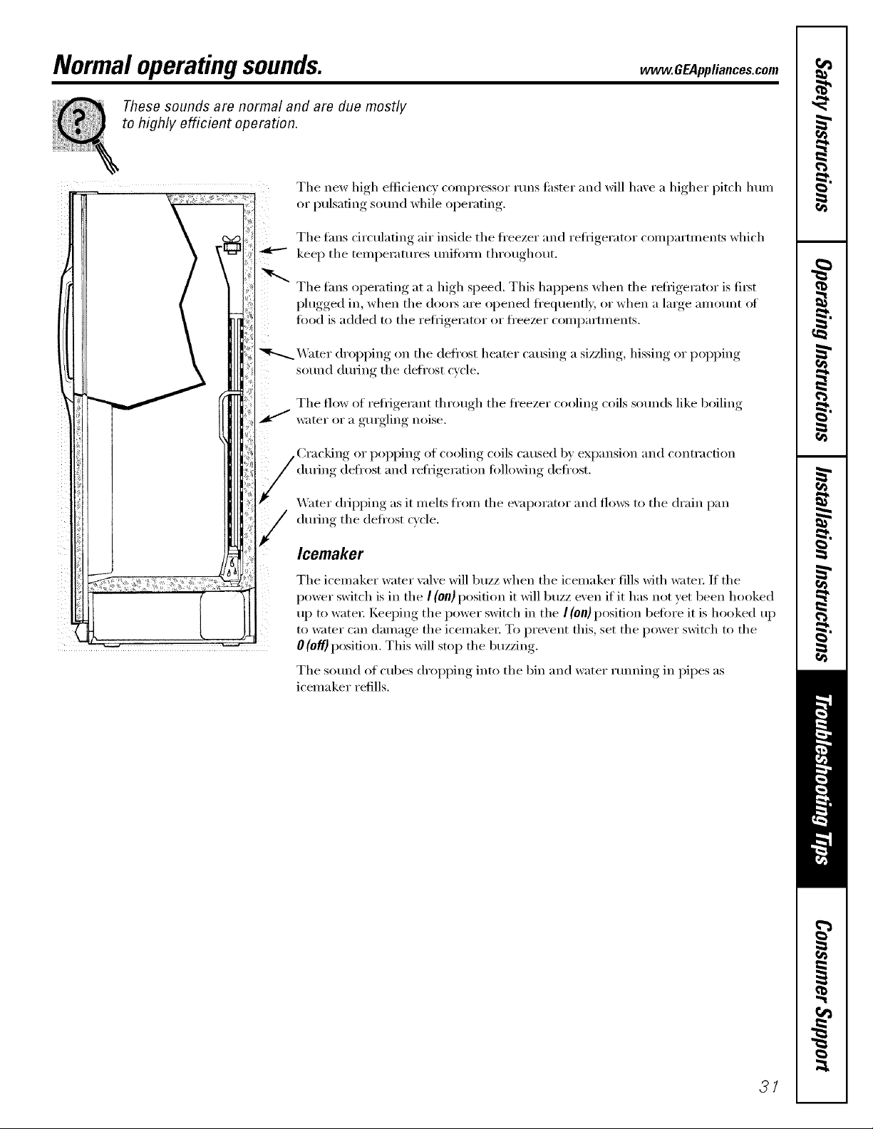
These sounds are normal and are due mostly
to highly efficient operation.
The new high efficiency compressor runs tipster and will haxe a higher pitch lmm
or I)ulsafing, sound while oi)erating.
The tans circtflafing air inside the fl'eezer and refi_igerator comparm_ents which
kee I) the temperatm'es unifi)i_n throtlghotlt.
The tans operating at a high speed. This happens when the refl_igerator is fi_t
I)lugged,, in when the (loo_ are I° )ened f'e(luentl_ or when a large, amount of
t0od is added to the reti_igerator or ti'eezer compartments.
_4]_ter dropping on the defl'ost heater causing a sizzling, hissing or popping
sound dtwing the defrost cycle.
The flow of reii_igerant through the freezer cooling coils sotmds like boiling
water or a gurgling noise.
of cooling coils caused by expansion and contraction
dtwing def'ost and refrigeration following defi'ost.
_&_ter dripping as it melts from the exaporator and flows to the drain pan
(hwing the defrost c}cle.
Icemaker
The icemaker water valve will buzz when the icemaker flls with _:_te_: If the
power switch is in the I (on) position it will buzz even if it has not yet been hooked
up to water: Keeping the power switch in the I (011)position beii)re it is hooked up
to water can damage the icemake_: To prevent this, set the power switch to the
0 (off} position. This will stop the buzzing.
The sotmd of cubes dropping into the bin and water rtmning in pipes as
icemaker refills.
31
 Loading...