

GE PSS25MGNAWW, PSS25MGNACC, PSS25MGNABB Owner’s Manual
GEApp/iances.com
Safety Instructions ........... 2-4
:/3
Operating Instructions
Additional Features ............ ] 0
Automatic Icemaker ........... 12
Care and Cleaning .......... 14, 15
Crispers and Pans ............. 11
Ice and _'ater Dispenser ..... 13, 14
Refligerator Doors ............ 10
Replacing the Light Bulbs ....... 16
Shelves and Bins ............. 8, 9
TemperaUlre Controls ........... 5
TurboCool r'* . .................. 6
_'ater Fiher . .................. 7
Installation Instructions
Preparing to Install
the Refligeramr ............ 22, 23
Removing and Replacing Doors . .21
Trim Kits and Panels ........ 17-20
_'ater Line Installation ...... 24-28
Troubleshooting Tips ....... 30-32
Normal Operating Sounds ...... 29
Models23,25,27 and29
Profile C6te fi C6te
R frig rateurs
La sectionfran_aise commencea la page40
Profile Lado a Lado
Refrigeradores
La seccionen espafol empiezaen la pagina 74
Consumer Support
Consumer Support ..... Back Cover
Performance Data Sheet ........ 36
Product Registration ........ 33, 34
State of California Water
Treatment Device Certificate ..... 37
Warranty (Canadian) ........... 38
_'arrantv (U.S.) ............... 39
Write the model and serial numbers here:
#
#
Find these numbers on a label inside
the reti'igerator compartment at the
top on the right side.
200D2600P015 49-60185 11-01JR

IMPORTANTSAFETYINFORMATION.
READALLINSTRUCTIONSBEFOREUSING.
A WARNING!
Use this appliance only for its intended purpose as described in this Owner's Manual
SAFETYPRECAUTIONS
When using electrical appliances, basic safety precautions should be followed, including the following:
_,':;This refl-igerator must be properly installed
and located in accordance with tl/e Installation
h_structions beiore it is used.
_,':;Do not allow children to climb, st;rod or hang
on the shelves in tile refl'igerato_: They could
damage tile refligerator and seriously iqitu'e
themselves.
:)::Do not touch the cold surli_ces in the fl'eezer
compartment when hands are damp or wet.
Skin may stick to these extremely cold surii_ces.
i,;:Do not store or use gasoline or other flammable
\:q_o_s and liquids in tile vicini F oI this or any
other appliance.
i,_:;In refiigerato_s with atltOll/atic icemake_s,
avoid comact with the moving parts of the
ejector mechanism, or with the heaOng
element located on tl/e bottom of tile icemake_:
Do not place finge_s or hands on tile automatic
icemaking mechanism while the reti_igerator
is plugged in.
i,_:;Keep finge_s out _ff tl/e "pinch point" areas;
clearances between the doo_ and between
the (loo_s and cabinet are necessmilv small.
Be careful closing (loo_s when children are
in the area.
i/:;Unplug tile refrigerator betore cleaning and
making repairs.
NOTE."Westronglyrecommendthat any servicingbe
performedby aquafifiedindividual.
i/:;Setting either or both controls to 0 (0If)does not
remove power to the light circuit.
::NDo not refl'eeze fl'ozen foods which have
thawed complemly.
2

DANGER!RISKOFCHILDENTRAPMENT
PROPERDISPOSALOFTHEREFRIGERATOR
GEAppliances.com
Child entrai)ment and suffocation are not i)rol)lems
of the past, Junked or abandoned refl_igeratm_ are
still dangerous...even if they will sit fin" "just a fi_w
days." If you are getting rid of yore" old refrigeratm;
please follow tile instructions below to hel I) prevent
accidents.
Before YouThrowAway YourOldRefrigerator
or Freezer:
i;_?Take off tile dome.
CFCDisposal
Ymr old refl_igerator may have a cooling system
that used CFCs (chlorofluorocarbons). CFCs are
believed to ham_ stratospheric ozone.
If you are throwing away yore" old refrigerator; make
sm'e tile CFC refl_igerant is removed fin" proper
disposal by a qualified se_wice_: If vou intentionally
release this CFC reflJgerant, you can be subject to
fines and imprisomnent under provisions of
enviromn ental legislation.
>_ I,eave tile shelves in place so that children max
not easilx climb inside.
USEOFEXTENSIONCORDS
Because ofpotential safety hazards under certain conditions, we strongly recommend against the use
of an extension cord.
However, ifxou must use an extension cord, it is absolutelx necessary that it be a UITlisted (in tile United
States) or a (;SA-listed (in (_anada), 3-wire grom_ding type appliance extension cord haxim,_ a ,gr°m_ding
type I)hw_ and outlet and that tile electrical rating, of tile cord be 15 amperes (minimum) and 120 xolts.

IMPORTANTSAFETYINFORMATION.
READALLINSTRUCTIONSBEFOREUSING.
a, WARNING!
HOWTOCONNECTELECTRICITY
Do not, under any circumstances, cut or remove the third (ground) prong from the power cord.
For personal safety this appliance must be properly grounded.
Tile power cord of this appliance is equipped with
a 3-prong (grounding) plug which inates with
a standard 3-prong (gro/mding) wall outlet to
minimize tile possibili F of electric shock hazard
fl'om this appliance.
Have the wall outlet and circuit checked by
a qualified electrician to make sure the outlet
is properly gromMed.
If the outlet is a standard 2-prong outlet, it is
yore" pelsonal responsibility and obligation to
have it replaced with a properly gro/mded
3-prong wall outlet.
Tile refl-igerator should always be plugged into
its own individual electrical outlet which has
a voltage rating that matches tile rating plate.
This provides tile best perflmnai_ce and also
I)rexents oxerloading, house wiring circuits which
could cause a fire hazard fl'om oxerheated wires.
Never tmi)lug )'ore" refl_igerator by pulling on
tile power cord. Mways grip plug firefly and pull
straight out fl'om tile outlet.
Repair or replace immediately all power cords that
have become fl'aved or otherwise damaged. Do not
use a cord that shows cracks or abrasion damage
along its length or at either end.
\4'hen nloving tile reflJgemtor away fl'Oln tile
wall, be careflfl not to roll over or danmge the
power cord.
USEOFADAPTERPLUGS(Ad_pte_p/ug_notpe_mittedinc_d_)
Because of potential safety hazards under certain conditions, we strongly recommend against
the use of an adapter plug.
HoweveI; if'you, Inust use an adaptei; where local
codes peI_nit, a temporary connection may be made
to a properly groulMed 2-i)rong wall outlet by use
of a UI Aisted adapter a\:filable at in ost local
hardware stores.
Tile linger slot in tile adapter must be aligned Mth
tile larger slot in tile wall outlet to provide proper
polarity in tile c(mnection of tile power cord.
When disconnecting tile power cord ti'oln tile
a(laptei; always hold tile adapter in place with one
hand while pulling tile power cord plug with tile
other hand. If this is not done, tile adapter gro/md
temfinal is very likely to break with repeated use.
If the adapter gro/md temfinal breaks, DO NOT
USEthe refrigerator tmtil a proper gro/md has
been established.
Attaching the adapter ground terminal to a waft outlet
cover screw does not ground the appliance unless the
cover screw is metal, and not ihsu/ated, and the waft
outlet is grounded through the house wiring. Youshould
have the circuit checkedby a qualified electrician to
make sure the outlet is properly grounded
READANDFOLLOWTHISSAFETYINFORMATIONCAREFULLY.
SAVETHESEINSTRUCTIONS
4

Aboutthe temperaturecontrols. GEAppliances.com
The temperature controls are preset in the factory at 5 for both
the refrigerator and freezer compartments. Allow 24 hours for the
temperature to stabilize to the preset recommended settings.
Several adjustments may be required. Each time you adjust
controls, allow 24 hours for the refrigerator to reach the setting
you have selected.
Setting either or both controls to 0 stops cooling in both the freezer
and refrigerator compartments, but does not shut off electrical power
to the refrigerator.
Controlsettings will vary based on personal preferences, usage and
operating conditions and may require more than one adjustment.
NOTE: Therefrigerator is shipped with protective film covering the
temperature controls. If this film was not removed during installation,
remove it now.
PerformanceAir FlowSystem
The Perfbmmnce ,&Jr How System is designed to ma_mize temperature control in the refrigerator and
fl'eezer compartments. This tmique spedal tbatm'e consists of the _r Tower along the back wall of the
reli_gerator and the Air Ttmnel on the bottom portion of the fl'eezer rear wall. Placing food in fl'ont of the
lou\'e_ on these components will not affect pe_fimnance. Although the Ah" Tower and the Air Ttmnel can
be removed, doing so will afl_'ct temperature performance. (For remox:fl instructions, on-line, 24 horns a
day, contact us at GEAppliances.com or call 800.GE.CARES. In Canada, contact us at geappliances.ca or
call 1.800.361.3400.)

About TurboCoolY
TurboCool
How it Works
TurboCoolrapidly cools the retiigerator
compartment in order to more quickly
cool fl)ods. Use TurboCoolwhen adding a
large amount of tood to the refligerator
compartment, putting away fi)ods alter they
have been sitting out at i'ooi11 temperature
or when putting away warm leftovers. It can
also be used if the refrigerator has been
without power fiw an extended period.
Once acti\:_ted, the compressor will turn on
immediateh' and the tiros will cycle on and
off at high speed as needed for eight horns.
The compressor will continue to mn tmtil
the refligerator compartment cools m
approximately 34°F (l °C), then it will cvcle
on and off to maintain this setting. _Mter 8
hom_, or if TurboCoolis pressed again, the
refrigerator compartment will return to
the original setting,
How toUse
Press TurboCooLThe refl_igerator
temperature display will show 9 (the coldest
setting),
_Mter TurboCoolis complete, the
refl_igerator compartment will return
to the original setting,
NOTES:The refligerator temperatm'e
cannot be changed dining
TurboCooL
The fl'eezer temperatm'e is not
affected during TurboCooL
When opening the refligerator
door during TurboCool,the liras
will continue to mn if they have
cycled (m.

About the water filter. (onsomemodels) CEAppliances.com
On some models
Place the top of the cartridge up
inside the cartridge holder and
slowly turn it to the right.
RESETWATERFILTER
HOLD3 SECS
Water Filter Cartridge
The _,_ater filter cartridge is located in tile
back upper fight corner of tile retiJgerator
COl//pa l'tl//ent.
When to Replace the Filter
There is a replacement indirator light for
tile water filter cartridge on tile dispense*;
This light will turn orange to tell you that
you need to replace tile filter soon.
Tile fiker cartridge shonkl be replaced
when the replacement indicator light turns
red or if tile flow of water to tile dispenser
or icemnker decreases.
Installing the Filter Cartridge
,I
O ]f_(m, are repl'miw,_, _ tile c'u'tridoe,_ , fiI_t
remo'_e tile 5)1done b} slowl)turning
it to the left. OO not pull down on tile
cartridge. A small amount of water
may drip down.
_FilI tile replacement cartridge with
_<_ter fi'om tile tap to allo_ for better
flow fl'om tile dispenser immediately
after installation.
I •inino_ up tile arro_ on tile c'u'tfidoe,
@
and tile c'u'tridoe,_ holdel, place tile
top of the new c'ulfidoe, _ up inside
tile lmldel: Do notpush it up into
tile hokiel:
O P,un water fi'om tile dispenser fbr
3 minutes (about one and a half
galhms) to clear tile s}_steFa and
prevent sputtelJng.
PIess and hold the RESET WATER FILTER
pad on tile dispenser fbr 3 seconds.
NOTE."A newly-installed water filter
camidge may cause water to spurt fi'om
tile dispensel:
Filter Bypass Plug
'You must use tile filter b}pass plug
when a replacement filter cartridge is not
a_;dlable, Tile dispenser and tile icemaker
will not operate without tile filter or filter
bypass plug.
ReplacementFilters:
To order additional filter cartridges
in the United States, visit our Webs#e,
GEAppliances.cmn,or carl GE Parts
andAccessories, 800.626.2002.
Suggested Retail $34.95 USD
Customers in Canada should consult
the ? ello_ pages fi)r tile nearest Camco
Service Centel:
Slowly turn it to the right until the filter
caintfidge stops. O0 NOT OVERTIGHTEN.
_s you turn tile cartridge, it will
automatically raise itself into position.
Cartridge will rotate about 1/4 turn.
7
Abouttheshelvesandbins.
Not all features are on all models.
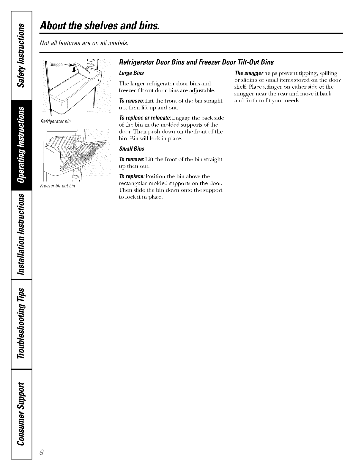
Refrigerator Door Bins and Freezer Door Tilt-Out Bins
LargeBins
The larger ref_igerator door bins and
fl'eezer filt-_mt door bins are ac!justable.
To remove: i,ifi the front ot the bin straight
up, then lilt up and out.
Refrigerator bin
Freezer tilt-out bin
Toreplace er relecate: Engage the back side
of the bin in the molded sui)ports of the
door Then push down on the fl'ont of the
bin. Bin will lock in place,
SmallBins
To remove: Lift the fl'ont of the bin straight
up then out.
Toreplace:Position the bin above the
rectangular molded supports on the doo_:
Then slide the bin down onto the support
to lock it in place.
The snuggerhelps prevent tipping, spilling
or sliding of small items stored on the door
shelf, Place a finger on either side of the
snugger near the rear and move it back
and torth to fit wmr needs.
8

Not all features are on all models.
Slide-Out Spillproof Shelf
i!j i¸; i i¸i i:¸¸¸
fill!
Press tab and pull shelf
forward to remove
The slide-out spillprooI shelf allows )ou
to reach items stored behind othe_. The
special edges are designed to hel I) prexent
spills fl'om dripping to lower shelves.
Toremove:
Slide the shelf out until it reaches the stop,
then press down on the tab and slide the
shelf straight ()tit.
To replace or relocate:
I,ine the shelf up with the supports and
slide it into place. The shelf can be
rel)ositioned when the door is at 90 ° or
more. To reposition the shell slide the shelf
past the stops and angle downward. Slide
shelf down to the desired position, line up
with the supports and slide into place.
Make sure you push the shelves all the way back
in before you close the doo_
GEAppliances.com
j I_
QuickSpace TM Shelf
This shelf splits in half and slides under
itself for storage of tall items on the shelf
This shelf can be removed and replaced
or relocated just like Slide-Out Spillproof
Shelves.
Freezer Baskets
Toremove, slide out to the stop position,
lift the ti'ont past the stop position, and
slide out.
Slide-Out Freezer Shelves
Toremove, slide out to the stop position,
lift the ti'ont past the stop position, and
slide ()tit.
On some models, this sheff can not be used
in the lo_est position,
Makesureyoupushthebasketsall thewayback
in beforeyouclosethe doo_
Makesureyoupushtheshelvesall the wayback
in beforeyouclosethe doo_
) Fixed Freezer Shelves
To remove, lift the shelf up at the left side
and then bring the shelf out.

Abouttheadditionalfeatures.
Not all features are on all models.
Removable Beverage Rack
The bexerage rack is designed to hold
a bottle on its side. It can be attached
)
to am slide-out shelf,
Abouttherefrigeratordoors.
Refrigerator Doors
Toinstall:
O iJne up tile large part ot the slots on
the top of the rack with the tabs trader
the shell
Then slkle the rack back to lock it
in place.
t=zw
When the door is only partially open,
it will automatically close.
Beyond this stop the door will
stay open.
The refl'igerator (lom_ may teel different
than the ones you are used to. The special
door opening/closing teatm'e makes sure
the doo_5 close all the way and are secm'elv
sealed.
When opening and closing the door you
will notice a stop position, If the door is
opened past this stop point, the door will
remain open to allow you to load and
tmload ibod more easily, When the door
is only partially open, it will automatically
close.
Door Alignment
If doox5 are unexen, a_!just the refrigerator
dooi;
0 I-'l_i:lg a 7_1611.s_,cket _i%iI'en('h,o_t,I'II the
d r a(!jmtin_ ,_crew t the right tt
raise the door; to the leti to lower it.
(A nylon plug, imbedded in the
threads of the pin, prevents the pin
fl'om turning unless a wrench is used.)
The resistance )ou feel at the stop
position will be reduced as the door
is loaded with food.
AJteI" one oi" {WO ttlYns of tile wI'ench,
open and close the refrigerator door
and check the aligmnent at the top of
the (looi_,
10

Aboutthe crispersand pans. GEAppliances.com
Not all features are on all models.
Fruit and Vegetable Crispers
Excess water that may accumulate in tile
bottom of tile drawet_ should be wiped (h_':
On some models, tile botton/drawer has
a covet" that slides back as the drawer is
opened. This allo_:s fitll access to the
drawer; _&sthe drawer is closed, the cover
will slide fin'ward into its original position,
Hi _ LO
Adjustable Humidity Crispers
Slide tile control all tile wa_ to tile
Hlsetting to proxide high humidity
recommended fin" most xegetables.
Convertible Meat Pan
The convertible meat pan has its own
cold air duct to allow a stream of cold air
ti'oI/l tile fl'eezer COilll)artillent to l]ow to
tile pan.
The variable temperature control regulates
tile air flow fl'om tile Climate Keeper:
Aboutcrisperremoval.
Slide tile control all tile wa) to tile
LOsetting to proxide lower h umidit)
lexels recommended fi)r most fl'uits.
Set tile control to tile coldestsetfing to store
fresh meats.
Set tile control to coldto convert tile pan
to nom_al refl_igerator temperature and
provide extra vegetable storage space. The
cold air duct is turned off, ¼1fiable settings
between these extremes can be selected.
Not all features are on all models.
Crisper Removal
Crispel_ can easil} be removed b_ l_ullin"
tile drawer straight (lilt and lifting the
drawer up and o_er tile stop location.
If the door prevents you fi'om taldng out
tile drawer% first tW to remove tile door
bins. If this does not offer enough
clearance, the refi_igerator will need to
be rolled ,fbrward until tile door opens
enough to slide tile (h'awel_ out. In some
cases, when you roll tile refrigerator out,
you will need to move tile refl_igerator
to tile left or right as }_m roll it out.
11

Abouttheautomaticicemaker.
A newly-installed refrigerator may take 12to 24 hours to begin making ice.
Power Automatic Icemaker
Switch
Pull the upper freezer shelf straight
out to access the icemaker. Always
be sure to replace the shel_ The
shelf can be used for storage.
Icemaker
The icemaker Mll produce seven cubes
per cycle-apI)roxinmtely 100-130 cubes
in a 24-hour period, depending on fl'eezer
COillpai'tlllent [eillpei'attli'e_ i'OOill
teml)eratm'e, nmnber of door openings
and other use conditions.
If the refl_igerator is operated befi)re the
water connection is made to the icemaket;
set the power switch in the 0 (Of/)position.
When the reti_igerator has been cmmected
to the water sui)ply, set the power switch to
the I (on) position.
The icemaker _villfill with water when it
cools to 15°F (-10°C). A newl}qnstalled
reflJgerator Inay take 12 to 24 houi_ to
begin inaking ice cubes.
Throw away the first tew batches ot ice
to allow the water line to clea_:
Be sm'e nothing interteres with the sweep
of the feeler amL
When the bin fills to the level of the feeler
am_, the icemaker will stop producing ice.
It is nomml fi:,r several cubes to be joined
together:
If ice is not used fl'equenfly, old ice cubes
will become cloudy, taste stale and shrink.
NOTE: Inhomeswith lower-than-averagewater
pressure,you mayhear the icemakercycle multiple
times whenmaking onebatch of ice.
Ice Storage Drawer
Toaccess ice, pull the drawer fin'ward.
Toremove the drawer, pull it straight out and
lift it past the stop location.
12
About the ice and water dispenser. (onsomemodels) CEApp/iances.com
On some models
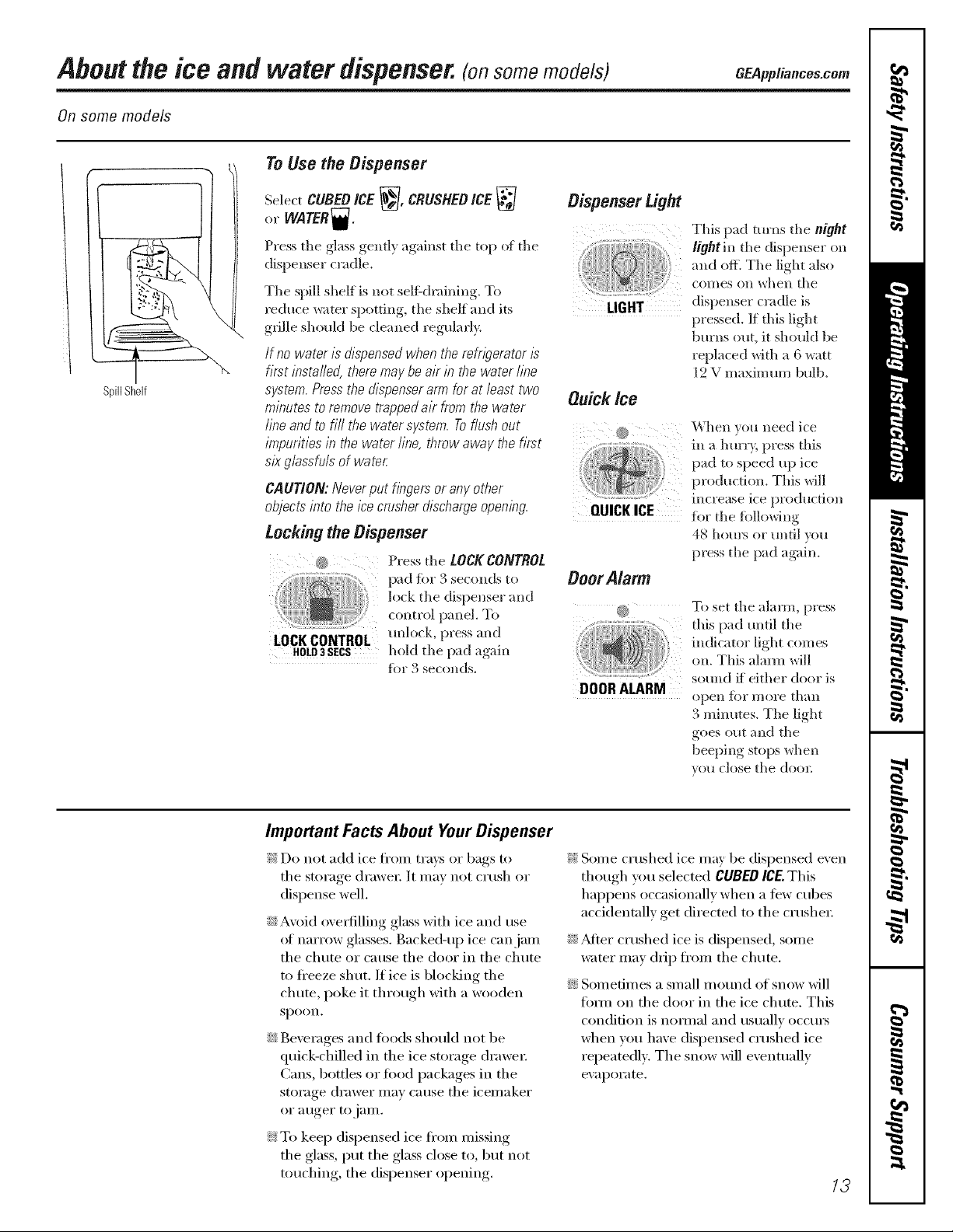
To Use the Dispenser
SpillShelf
SelectCUBEDICE_], CRUSHEDICE
or WATER_.
Press tile glass gentl) against tile top of tile
dispenser cradle.
Tile spill shelf is not seltkh'aining. To
reduce _ater spotting, tile shelf and its
grille shotdd be cleaned regularly.
If no water is dispensed when the mfr/_Temtor/s
first installed,there may be air in the water line
system. Press the dispenser arm for at least two
minutes to remove trapped a/r from the water
line and to fill the water system. Toflush out
impuritiesin the water line, throw away the first
six glassfuls of water.
CAUTION: Never put hbgers or any other
objects into the icecnJsherdischarge opembg.
LocRingthe Dispenser
_ Press tile LOCKCONTROL
lock tile dispense_ and
control panel, To
LOCK CONTROL mflock, press and
HOLD3SECS hold tile pad agaill
for 3 seconds.
Dispenser Light
Ou_k_e
QUICKICE
OoorAlarm
DOORALARM
This pad turns tile night
light in tile dispenser on
and off. Tile light also
coI/les Oll _,#hen tile
dispenser cradle is
pressed. If this light
burns out, it should be
replaced with a 6 watt
12 V maximum bulb.
When you need ice
ill a h{/IT}', pFess this
pad to si)eed up ice
production. This will
lllCFe;tse ice production
fi)r tile fi)llowing
4_ hom_ or tmtil _ou
press the pad again.
To set the alarm, press
this pad until the
indicator light c(m/es
on. This alaml will
sound _f either door is
()|)ell toF _//(}l'e thall
3 minutes. Tile light
goes out and dw
beeping stops when
you close the dooc
Important Facts About Your Dispenser
_i::Do not add ice fl'om trm_s or bags to
tile storage (h'awe_: It may not crush or
dispense well.
i_i;:Avoid ove_l'illing glass with ice and use
(ff narrow glasses. Backed-up ice can jam
tile chute or cause tile door in tile chute
to ti'eeze shut. If ice is blocking tile
chute, poke it through with a wooden
spoon.
i;_;:ge;'erages and toods should not be
quick-chilled in the ice storage drawe_:
Cans, bottles or food packages in the
storage drawer may cause tile icemaker
(sr a/iger to jaIll.
_i::To keep dispensed ice ti'om missing
tile glass, put tile glass close to, but not
touching, tile dispenser opening.
_i::Some crushed ice may be dispensed even
though you selected CUBEDICE.This
happens occasionally when a tew cubes
accidentally get directed to the crushex:
i;_;:_Mter crushed ice is dispensed, some
water may drip fl'om tile chute.
N Sometimes a small mo/md of snow will
timn on tile door in tile ice chute. This
condition is hernial and usually occm_
when you have dispensed crushed ice
repeatedly. Tile snow will eventually
evapoi'ilte.
13
Aboutthe ice and water dispenser.
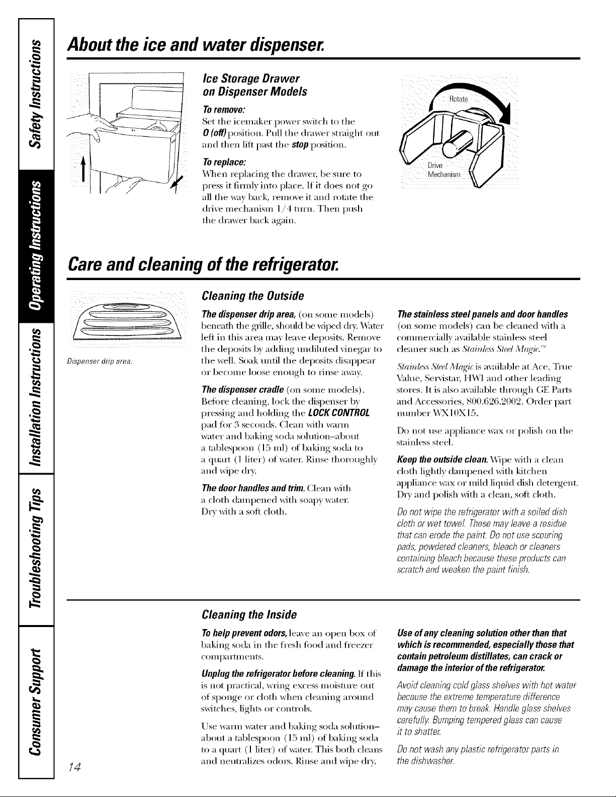
Ice Storage Drawer
on Dispenser Models
To remove:
Set the icemaker power switch to the
0 (off)position. Pull the drawer straight out
and then lift past the stop p()sifion.
Toreplace:
_'_qt en rel)lacino,_ the (h'awe_, be sure to
press it firefly into place. If it does not go
all the wax back, i'eilloxe it and rotnte the
drixe mechanism 1/4 tm'n. Then push
the drawer back again.
Careand cleaningof therefrigerator.
Cleaning the Outside
Drive
Mechanisn
Dispenser drip area.
The dispenser drip area, (on some models)
beneath the grille, shotfld be wiled (h_:. Water
left in this area may leave deposits. Remove
the deposits by adding tmdiluted vinegar to
the well. Soak tmtil the deposits disappear
0I" becoi/le loose enotlgh to I]nse "d%;Iv,
The dispenser cradle (on some models).
Before cleaning, lock the dispenser 1)v
pressing and hoMing the LOCK CONTROL
pad fiw 3 seconds. Clean with wmm
water and baking soda solution-about
a tablespoon (l 5 ml) of baking soda to
a quart (l liter) of water: Rinse thoroughly
and wipe dry.
The door handles and trim. Clean with
a cloth dampened with soapy watex;
Dry with a soft cloth.
Thestainless steel panels and doorhandles
(on seine Inodels) can be cleaned with a
commercially available stainless steel
cleaner such as Slainle,_,_Sled M(_'i(:.''_
Slainh_ss Sled Mrlq4_ is available at Ace, Tree
Value, Se_Mst;n; HWI and other leading
stores. It is also awfilable through GE Parts
and Accessories, 800.626.2002. Order part
nulnber X_3X10X 15.
Do not use appliance wax or polish on the
stainless steel.
Keep the outside clean. Wipe Mth a clean
cloth lightly dampened Mth kitchen
appliance wax or mild liquid dish detergent.
Dry and polish Mth a clean, soft cloth.
Donot w/_getheTernS?oratorwitha soileddish
cloth orwet towel Thesemayleavea residue
thatcanerodethepain_Donotusescouring
pads,powderedcleaners,bleachorcleaners
containingbleachbecausetheseproductscan
scratchandweakenthepaintfinish.
Cleaning the Inside
To help prevent odors, leave an open box of
baking soda in the fl'esh food and fl'eezer
COII/l)a I'tlIlents,
Unplug the refrigerator before cleaning. If this
is not practical, wring excess moisture out
of sponge or cloth when cleaning around
switches, lights or controls.
Lrse wam_ water and baking soda solution-
about a tablespoon (15 ml) ot baking soda
to a quart (1 liter) el water: This both cleans
/4
and neutralizes o(lo_. Rinse and wipe (hT:
Useof any cleaning solution other than that
which isrecommended, especially those that
contain petroleum distillates, can crack or
damage the interior of the refrigerator.
Avoid cleaning cold glass shelves with hot water
because the extreme temperature difference
may cause them to break. Handle glass shelves
carefufl_zBumping tempered glass can cause
it to shatter
Donot washanyplasticrefngeratorpartsin
thedishwasher

Behind the Refrigerator
GEAppliances.com
Be careful when moving the refi_gerator
away fl'on_ the wall. M1 types of floor
coverings can be damaged, particularly
cushioned coverings and those with
eIllbossed S/liS[_lces.
Pull the refligerator straight out and return
it to position by pushing it straight in.
Moving the refrigerator in a side direction
may result in damage to the floor covering
or reli_igerato_:
Preparing for Vacation
For long \;l('ations or absen('es_ rell/ove
fi)od and Ulq)lug the reli_igeratoi: Clean
the interior with a baking soda solution
of one tablespoon (15 ml) of baking soda
to one quart (1 liter) of water: i,eave the
doors open.
Set the icemaker power switch to the
0 (off) position and shut off the water supply
to the reflJgerato_:
When pushing the refrigerator back, make sure
you don't roll over the power cord or lcemaker
supply line (onsome models).
If the temperature can drop below fl'eezing,
have a qualified servicer drain the water
supply system (oil soine models) to prevent
serious propert), dainage due to flooding.
Preparing to Move
Secure all loose items such as shelves and
drawei_ by taping them securely in place
to prevent damage.
X4]_en using a hand track to move the
refi_igeratot; do not rest the ti'ont or back
(ff the retiigerator against the hand truck.
This could damage the refrigerator: Handle
only ti'om the sides of the reli_igerat(m
Be sure the refn)erator stays/b an upright
position during moving.
15

Replacingthe lightbulbs.
Setting either or both controls to 0 does not remove power to the light circuit.
_____ Refrigerator Compartment--Upper Light
Unplug the refl'igerator.
0
The bulbs are located at the top ot the
0
Tabs
compartment, inside the light shield.
On some models, a screw at the fl'ont of
the light shield will have to be removed.
To remoxe the light shield, press in on
@
the tabs on the sides of the shield and
slide fi)rward and ()tit.
Refrigerator Compartment--Lower Light
O _Mter replacing the bulb with an
appliance bulb of the same or lower
wattage, replace the light shield and
scrm_:s (on some models). When
replacing the light shield, make sure
that the tabs at the back of the shield fit
into the slots at the back ot the light
shield housing.
Plug the reti_igerator back in.
This h_?htis located above the top drawer
O Unplug the refrigerator
@ Remove the convertible meat drawer
control knob by pulling straight ()tit.
lift the light shield up and pull it out.
Freezer Compartment
Unplug the refligeratoi:
Remove the shelf just above the light
shield. (The shelf will be easier to
remove if it is emptied fiist.) On some
models, a screw at the top of the light
shield will need to be removed.
O To remoxe the light shield, press in on
the sides, and lift up and ()tit.
Dispenser
@ _Mter rei)lacing, the bulb with an
appliance bulb of the salne or lower
wattage, replace the shield and
the knob.
0 Plug the refrigerator back in.
Replace the bulb with an appliance
bulb of the same or lower wattage,
and reinstall the light shield. X*Vhen
reinstalling the light shield, make
sure the top tabs snap securelv
into place. P,eplace the screw (on
some models).
0 P,einstall the shelf and plug the
refl'igerator back in.
16
Unplug the refligerat(n:
The bulb is located on the
dispenser under the control panel.
Remoxe the light bulb by turning
it counterclockwise.
Replace the bulb with a bulb of the
SaIl/e size and watta ,e
O Plug the refrigerator back in.

Trimkits anddecoratorpanels.
For CustomStyl# Mmodels
Read these instructions completely and carefully.
BeforeYouBegin
Some models are equipped with trim kits that aflow you to instafl door panels. You can order
pre-cut black, white, bisque or stainless steel decorator panels from GE Parts and Accessories,
800.626.2002,or you can add wood panels to match your kitchen cabinets.
Panels less than 1/4" (6 mm) thick
\._l_en installing wood panels less than 1/4" (6 ram) thick, you need to create a filler panel, such as 1/8"
(3 ram) cardboard, that will fit between the ti_ce of the door and the wood panel. If you are installing the
pre-cut decorator panels, pre-cut filler panels are included in the kit. The combined thickness of the
decorator or wood panel and the filler panel should be 1/4" (6 ram).
Panels 1/4" (6 mm)thick or less
I/4"(6 mm) Max.
3/4" (19 mm) or Raised Panel
A raised I)anel design, screwed or _,,lued to a l/4" (6 ram) thick backing, or a " (
can be tlsed. The _isecl i)ortion of the panel illtlst be thb_icated to i)emfit clearances of at least 2" (5.1 cm)
fl'om the handle side fin" fingertip clearance.
Panels thicker than 1/4" (6 ram), up to./4 (l 9 ram) ma_mum, will require that the outer :)/16
(8 ram) of panel perimeter be no thicker than 1/4" (6 ram).
3/4 (l .) ram) umted board
Weightlimitationsfor custompanels:
FreshFood38Ibs.(17kg)max.
FreezerDoor28Ibs.(13kg)max.
Panels thicker than 1/4" (6mm)
5/16" (8 turn)
1/4"(6mm)
ThickBacking
2"(5.1cm) I lllll __
ili[11 I -''- Refrigerater
Door
17

Trimkits.
Dimensions for Custom Wood Panels
FreezerPanel
WithoutDispenser
Cut 1/8"
out ,-_ _,-(3 mm)
1 ',',
t
5/16"
(8mm}
67%2"
(171cm)
FRONT
_ I 141%2" ,_
(36.8cm)
FreezerPanel
WithDispenser
Cut 1/8"
out --_, ,_'-(3 mm}
J_ ,,i i
177X'
(45.4cm)
!
i FRONT
141%Z' .__
(36.8cm)
33%"
(85.4cm)
FreshFoodPanel
1/8" Cut
(3mm)--_f f_- out
FRONT
191%2" _.__
(49.5cm}
67%Z'
(171cm)
,, _,
' ' 5/16"
I-
""{ (8ram)
The areas at the top of the panels need to be cut out of the panels.
18

insertingthedoorpanels.
Read these instructions completely and careful/g
0 Insert the Freezer Panel and Fresh FoodPanel
Carefully push the freezer panel in until it slides
into the slot behind the door handle, Push the filler
panel (required with some door panels) in behind
the decorator panel. Repeat fin" fl'esh fi)od panel.
0 Insert the Bottom Freezer Panel (on dispenser models).
Carefull) push the panel in m_til it slides into the (required with some door panels) in behind the
slot behind the door handle, Push the filler panel decorator panel,
0 Attach the TopTrimon the Freezer and FreshFood Doors.
The Top Trim can be fimnd inside the refi_igerator each (loo_: Hand tighten only. Make sure that the
compartment, top _ff each panel fits snugly behind the lip _ff the
_]th a T-20 T(nxdrive_; attach the Top Trim, using Top Trim.
two scre_:s on each Top Trim piece, to the top of
If )ore" model has a dispense_; this step onl)applies
to the fl'esh fi)od panel and top fl'eezer panel,
Cut-Out
SideTrim
/9

Insertingthedoorpanels.
O install the Side Trim.
These pieces are tucked inside the refl_igerator door
handle.
Do not remove the protective film on the outside of the
Side Trimuntil the Side Trimis instafled.
Fit the bottom of the Side Trim under the Bottom
Trim as illustrated.
Hold the Side Trim against the flxmt filce of the
decorator panels and fit the Side Trim trader
the Top Trim. Make sm'e the magnetically attached
Side Trim is fitted correctly and that you are
satisfied with the appearance of all the parts.
2O
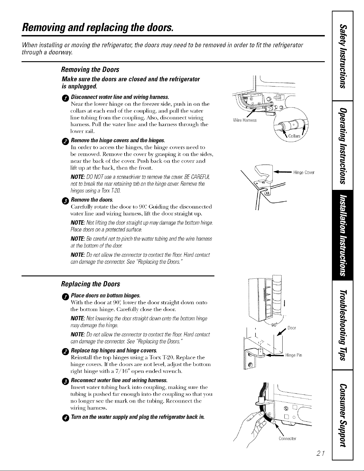
Removingandreplacing thedoors.
When installing or moving the refrigerator, the doors may need to be removed in order to fit the refrigerator
through a doorway.
Removing the Doors
Make sure the doors are closed and the refrigerator
is unplugged.
0 Disconnect water line and wiring harness.
Near tile lower hinge on tile fl'eezer side, push in on the
colla_ at each end of tile coupling, and pull tile watei"
line robing fl'onl tile coupling. _Mso, disconnect wi_ing
harness. Pull tile water line and tile harness through tile
h)wer rail.
0 Remove the hinge covers and the hinges.
In order to access tile hinges, tile hinge cove_ need to
be removed. ]{elno\'e tile cover b)' grasping it on tile sides,
near the back of the cove_: Push back on the cover and
lift up at the back, then the fl'ont.
NOTE: DONOTusea screwdriverto removethe cover BECAREFUL
not tobreak the rear retaining tabon the hinge cover Removethe
hingesuslbga Torx520.
Remove the doors.
Carefllllv rotate tile door to .)0. (;uiding tile discom_ected
water line and wi6ng harness, lift tile door smfight up.
NOTE: Not lifting the doorstraight up may damagethebottom hinge.
Placedoorsona protectedsurface.
NOTE: Becareful not to pinch the water tubingand thewire harness
at thebottom of the door
NOTE: Donot allow the connectorto contact the floor Hardcontact
can damagetheconnector See "Rep/aclbgthe Doors."
( o
......
WireHarnes_
_Hinge Cover
Replacing the Doors
Place doorson bottom hinges.
O _'_ith tile door at 90_' lower tile door straight down onto
tile bottom hinge. Careflfllv close tile doo_:
NOTE: Not lowering thedoorstraight down onto thebottom hinge
may damagethehinge.
NOTE: Donot allow the connectorto contact the floor Hardcontact
can damagetheconnector See "Replacingthe Doors."
Replace top hinges and hinge covers.
Reinstall tile top hinges using a Torx T-20. Replace tile
hinge cove_s. If the doo_s are not level, ac!iust the bottom
_ight hinge with a 7/16" open ended wrench.
Reconnect water line and wiring harness.
Insert water tubing back into coupling, making sure tile
tubing is pushed fin" enough into tile coupling so that you
no hmger see the mark on the tubing. Reconnect the
wi_ing harness.
Turnon the water supplyand plug the refrigerator back in.
Oonnector
2/

Installation
Refrigerator
Instructions
Models 23,25,27 and29
Questions?Call 800.GE.CARES(800.432.2737)or Visitoro-X_ebsite.t: GEAppliances.com
In Canada,call 1.800.361.3400or VisitoroX_ebsite,t: geappliances.ca
BEFORE YOU BEGIN
Read these instructions completely and carefully.
• IMPORTANT - hese
instructions for local inspector's use.
" IMPORTANT - Obse,,'e.U
gox eFllillo codes alld oYdin[lllCeS.
• Note to Installer - Be sm'e to leave these
instructions _ith tile Consumer.
• Note to Consumer - Keep these instructions
for ftlttlre reference.
• Skill level- Installation of this appliance requires
basic mechanical skills.
• Completion time - Refrigerator Installation
15 minutes
• Proper installation is tile responsibilit} of tile
installer.
• Product fhilm'e due to improper installation is not
covered under tile \'_'arrant}.
WATER SUPPLY TO THE ICEMAKER
(ON SOME MODELS)
If the refiigerator has an iceroaker, it will have to be
connected to a cold water line. AGE water supply kit
(containing robing, shutoff wdve, fittings and
instructions) is available at extra cost flx)ro voro" deale_;
by visiting oro" Website at GEAppliaaaces.coro (in
Canada at geappliaalces.ca) or fl'om Parts and
Accessories, 800.626.2002 (in Canada 1.888.261.3055).
CLEARANCES
Pdlow the fi_llowing clearances fl_r ease of installation,
proper air circulation and phunbing and electrical
connections:
23' 25', 27' mad 29'
•Sides 1/8" (4 taro) 1/8" (4 taro)
• Top 1"(2.5 cro) 1"(2.5 cro)
• Back 1/2" (13 rom) 1" (2.5 cro)
ROLLERS
The rollers have 3 purposes:
• Rolle_ a(!iust so tile door closes easily when opened
about hallway: (Raise tile ti'ont about 5/8" [16 roro] fl'oro
tile rio(m)
• Rolle_ a_!just so tile refligerator is fired) posidoned on
tile floor and does not wobble.
• Rollet_ allow you to move tile refl_igerator away fl'om tile
wall tot cleaning.
Final leveling a(!iustments should be made after the
retiigerator has been installed.
To adjust the rollers on 25', 27' mad 29'models:
• Turn tile roller ac!itlsting _ H IJ
screws dockwise to raise "_'_'_-_1 I|
the refiigerat(m
coro,terclockwise to lower_ fl
OI" _v_'elIch, OY _111
a ('i tl'_tnble wrencl/" _=" k J
Rolleradjustingscrew
REFRIGERATOR LOCATION
• Do not install the refrigerator where the teroperatm'e
will go below 60°F (l 6°C) because it will not rtro otten
enough to maintain proper mmperatm'es.
• Do not install tile refligerator where tile teroperamre
will go above 100°F (37°(;) because it will not pertmro
properl>
• Install it on a floor strong enough to support it fillly
loaded.
22

Installation Instructions
BEFORE YOU BEGIN
ROLLERS (CONT.)
To adjust the rollers on 23' models:
@ P.emox e the base _ofille b', oi)ening, the dom_
removing the screws at each end, and pulling
it straight out.
ac!iusting screws
dockwise to raise the
refl_igeratm;
comaterdockwise to
lower it. Use a 3/8"
hex socket or wI'ench,
_Tum the fl'ont roller ______
or an a({iustable
wI'ench, " '
@ These models also have rear a(!justable rolle_5 so w,u
can align the refrigerator with vom" kitchen cabinets.
Llse a long-handled 5/16" socket wrench to turn the
screws t0r the rear rolle_5-dockwise to raise the
refl_igeratm; comlterclockwise to lower it.
Replace the base grille.
DOOR ALIGNMENT
_Mter leveling, make sm'e that dom_ are even at tile top.
To make the doors even, adjust the refl_igerator doo_:
@ Usnlg a 1/16 socket wrench, tuln the dora adlustnlg
screw to the right to raise tile doo_, to tile left to
lower it. (A nflon plug, imbedded in the threads ot
tile pin, prevents tile pin fl'om tm'ning tmless a
wrench is used.)
@ _&JieI" one oi" two ttlI'ns of tile wI'ench, open _lIld close
the refl_igerator door and check the alignment at the
top of tile (lomb.
DIMENSION AND SPECIFICATIONS
(for CustomStyle TM models)
O O
7!1/4 "
(178.4cm)
36"
(91.4cm)
24"
(61cm)
L "
3/4 (19mm)Airspace
24"
(61cm)
Cabinet
(1/2"(13mm)Gap+
1/4"(6mm)WallPlates)
25"(63.5cm)
Countertop
Toremovethebase
grille,openthedoors,
removethescrewat
eachendofthebase
grilleandthenpullthe
grillestraightout.
' J'L
7/16"SocketWrench
2
Raise
23
Installation instructions
iNSTALLiNG THE WATER LiNE
BEFORE YOU BEGIN
Reconlmended copper water stlpply kits are WXSX2,
WXSX3 or WXSX4, depending on tile amount of
tubing you need. Appr(wed plastic water supply lines
ate GE SmartConnect'" Refl'igerator Tubing
(WX08X10002, WX08X10006, WX08X10015 and
WX08X10025).
When connecting your refl'igerator to a GE Reverse
Osmosis Water System, tile only approved installation
is with a GE RVKit. For other reverse osmosis water
systems, follow tile manufimturer's recommendations.
If tile water supply to tile reflJgemtor is tom a Re','e_e
Osmosis \'_'ater Filtration System AND tile retiigerator also
has a water filte*; use tile reti-igerator's filter bypass plug.
Using the reiiigetator's wate_ filtration cartridge ill
coi_jtmcfion with the RO filter can result in hollow ice
cubes and slower water flow fl'om tile water dispensel:
This water lille installation is not warranted bv tile
refl'igerator or icemaker manufiicturer. Follow these
instructions carefully to minimize tile risk of expensive
water damage.
_%_ter hammer (water banging ill tile pipes) ill house
plumbing call cause damage to refl'igerator parts and
lead to water leakage or flooding. (;all a qualified
plmnber to correct water hammer betore installing
tile water supply line to tile refl'igerator.
To prevent bm'ns and product damage, do not hook
up tile water lille to tile hot water line.
If you use your refl'igerator betiwe connecting tile
water line, make sure tile icemaker power switch is
in tile 0 (Off} position.
Do not install tile icemaker tubing ill areas where
temperatures thll below freezing.
When using ally electrical device (such as a power
drill) during installation, be sure tile device is double
insulated or grounded in a manner to prevent tile
hazard of electric shock, or is battery powered.
All installations must be ill accordance with local
plumbing code requirements.
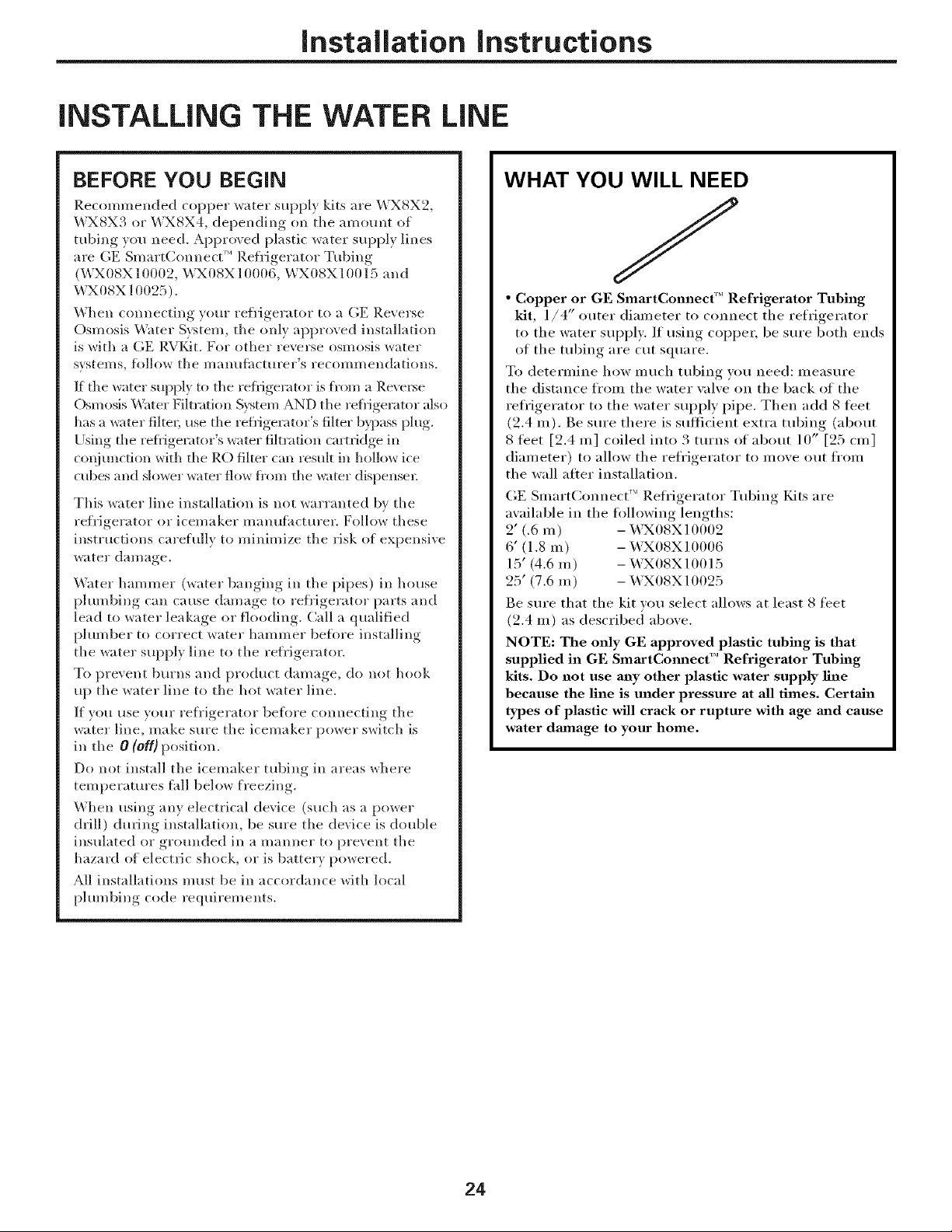
WHAT YOU WILL NEED
//
• Copper or GE SmartConnect'" Refrigerator Tubing
kit, 1/4" outer diameter to connect tile refrigerator
to the water supply: If using coppe_, be sm'e both ends
of tile tubing are cut square.
To determine how much tubing you need: measure
the distance from the water valve on the back of the
refrigerator to the water supply pipe. Then add 8 tibet
(2.4 m). Be sure there is sufficient extra tubing (about
8 teet [2.4 m] coiled into 3 tm'ns of about 10" [25 cm]
diameter) to allow the refrigerator to move out ti'oln
the wall after installation.
GE SmartConnect'" Refl'igerator Tubing Fdts are
available in the fi)llowing lengths:
2' (.6 m) -_,\_X08X10002
6' (1.8 m) -WX08X10006
15' (4.6 m) - WX08X10015
25' (7.6 m) - WX08X 10025
Be sure that tile kit you select allows at least 8 feet
(2.4 m) as described aboxe.
NOTE: The only GE approved plastic tubing is that
supplied in GE SmaactCmmect'" Refrigerator Tubing
kits. Do not use m_y other plastic water supply line
because the line is under pressure at all times. Certain
types of plastic will crack or rupture with age m_d cause
water dmnage to your home.
24

Installation instructions
WHAT YOU WILL NEED (CONT.)
Install the shutoff xalxe on the nearest frequentl) used
drinking water line.
• A GE water supply kit (containing tubing, shutoff
wflve and fittings listed below) is awfilable at extra
cost fl'om wmr dealer or fl'om Parts and Accessories,
800-626-2002 (in Canada 1.888.261.3055).
• A cold water supply. The water pressure must be
between 20 and 120 p.s.i. (1.4-8.2 bar) on models
without a water filter and between 40 and 120 p.s.i.
(2.8-8.2 bar) on models with a water filter.
• Power drill.
• 1/2" or adjustable wrench.
• Straight and Phillips blade screwdriver.
• Two 1/4" outer diameter compression nuts and
2 ferrules (sleeves)-to connect the COl)per tubing
to the shutoti xalxe and the refrigerator water xalxe.
OR
• If vou are using a GE SmartConnect _'_Refl'igerator
Tubing kit, the necessa_ T fittings are preassembled
to the tubing.
[] SHUT OFF THE MAIN WATER
SUPPLY
Turn on the nearest taucet long enough to clear
the line of water.
[] CHOOSE THE VALVE LOCATION
Choose a location for the valve that is easily
accessible. It is best to connect into the side of a
vertical water pipe. When it is necessary to connect
into a horizontal water pipe, make the connection
to the top or side, rather than at the bottom,
to avoid drawing oil any sediment fl'om the
water pipe.
[] DRILL THE HOLE FOR THE VALVE
Drill a 1/4" hole in the water pipe (even it using a
sell:piercing valve) using a sharp bit. Remove anv
burrs resulting fl'om drilling the hole in the pipe.
Take care not to allow water to drain into the drill,
Failure to drill a l/4" hole may result in reduced
ice production or smaller cubes.
• If w)ur existing copper water line has a flared fitting
at the end, you will need an adapter (available at
plumbing supply stores) to connect the water line to
the refl'igerator OR you can cut off the flared fitting
with a tube cutter and then use a compression fitting.
Do not cut tormed end ti'om GE SlnartConnect ''_
Refrigerator tubing.
• Shutoff valve to connect to the cold water line.
The shutoff valve should have a water inlet with a
minimum inside diameter of 5/32" at the point of
connection to the COLD WATER LINE. Saddle-type
shutoff wflves are included in many water supply kits.
Befi)re i)urchasing, inake sure a saddle-Vpe wflve
complies with your local plumbing codes.
25

Installation Instructions
iNSTALLiNG THE WATER LiNE (CONT.)
[] FASTEN THE SHUTOFF VALVE
Fasten the shutoff xalxe to the cold water pipe with
the pipe clamp.
PipeClamp_
Saddle-TypeJ -VerticalCold
ShutoffValve WaterPipe
NOTE: Commonwealth of Massachusetts Plumbing
Codes 248CMR shall be adhered to. Saddle wflves
are illegal and use is not permitted in Massachusetts.
Consult with wmr licensed plmnber.
[] TIGHTEN THE PIPE CLAMP
Tighten the clamp screws tmtil the sealing washer
begins to swell.
NOTE: Do not overtighten or you may cHIsh the
tubing.
Pipe
Clamp
-Washer
End
[]
CONNECT THE TUBING TO THE
VALVE
Place the compression nut and ti_Hule (sleeve) fin.
COl)per tubing onto the end of the tubing and
connect it to the shutoff wflve.
Make sm'e the tubing is flflly inserted into the valve.
Tighten the compression nut secm'elv:
For plastic tubing fl'om a GE SmartConnect'"
Refl'igerator Tubing kit, insert the molded end
of the tubing into the shutoff' wflve and tighten
compression nut until it is hand tight, then tighten
one additional turn with a wrench. Overtightening
IIl_lV Catlse leaks.
l_Compression
Saddle-Type_
ShutoffValve
Ib
PackingNut_
Outlet Valve_
NOTE: Commonwealth of Massachusetts Plmnbing
Codes 248CMR shall be adhered to. Saddle valves
are illegal and use is not pemfitted in Massachusetts.
Consult with wmr licensed plmnber.
-- Ferrule(sleeve)
|SmartConnect
Nut
[] ROUTE THE TUBING
Route the tubing between the cold water line and
the refl'igera tot.
Route the tubing through a hole drilled in the wall
or floor (behind the refl'igerator or a(!jacent base
cabinet) as close to the wall as possible.
NOTE: Be sure there is sufticient extra tubing
(about 8 feet [2.4 m] coiled into 3 tm'ns of about
10" [25 cm ] diameter) to allow the refl'igerator to
move out fl'om the wall alter installation.
[] FLUSH OUT THE TUBING
Tm'n the main water sui)ply on and flush out the
tubing until the water is clear.
Shut the water off at the water valve alter about
one quart (l liter) of water has been flushed
through the tubing,
26

Installation instructions
[] CONNECT THE TUBING TO THE
REFRIGERATOR
NOTES:
• Before making the connection to the refl'igerator,
be sure the reflJgerator power cord is not i)lugged
into the wall outlet,
• If your refl'igerator does not have a water filter
we recommend installing one if vour water SUl_ply
has sand or particles that could clog the screen
of the refl'igerator's water wflve, Install it in the
water line near the refl'igerator. ]f using GE
Slnart(]onnect '_ Refl'igerator Tubing kit, you
will need an additional tube (_X08X10002) to
connect the filter. Do not cut plastic tube to
install filter.
Some models have the refrigerator connection at
the end of tubing located outside the compressor
coiill)ai'tiilent access cover. Oil other models the
COIIll)I'eSSOI" COII/l)aI'tII/en[ access cover IIIHSt be
removed in order to access the refrigerator
connection at the water wflve.
[]
CONNECT THE TUBING TO THE
REFRIGERATOR (CONT.)
Insert the end of the tubing into the refrigerator
connection as flu" as possible. While holding the
tubing, tighten the fitting.
For plastic tubing fl'om a GE SmartConnect
Refl'igerator Tubing kit, insert the molded end of
the tubing into the refl'igerator connection and
tighten compression nut until it is hand tight, then
tighten one additional turn with a wrench,
Overtightening may cause leaks,
Fasten the tubing into the clamp provided to hold
it in a vertical position. You may need to pry open
the clamp.
One of the illustrations below will look like the
cmmection on your refrigerator.
Tubing
Clamp
On models using the refrigeration connection at
the water _al_e, remo_e the plastic flexible cap.
©
Place the compression nut and ter*ule (sleeve)
onto the end of the tubing as shown. On GE
SmartConnect P.efi'igerator Tubing kit, the nuts
are ah'eady assembled to the tubing.
1/4"
Compression
Nut
Ferrule --
(sleeve)
Refrigerator SmartConnecU
Connection Tubing
Tubing;lamp 1/4"Tubir
1/4"
Compressior
Nut
Ferrule
Refrigerator SmartConnect"
Connection Tubing
27

Installation Instructions
INSTALLING THE WATER LINE (CONT.)
[] TURN THE WATER ON AT THE
SHUTOFF VALVE
Tighten any connections that leak.
Reattach tile access co_ei',
I_PLUG IN THE REFRIGERATOR
&_rranoe tile coil of tubing so that it does not _ibrate
against tile back of tile refrigerator or against tile
wall. Push tile refrigerator back to tile wall.
START THE ICEMAKER
Set tile icemaker power switch to tile I (on)position.
Tile icemaker will not begin to operate tmtil it
reaches its operating temperature of 15°F
(-9°C) or below. It will then begin operation
automatically if tile icemaker power switch is in
tile I (On) position.
Power._.
switch
NOTE: In lower water pressure conditions, tile
water xalxe may turn on up to 3 times to (lelixer
enouoh water to tile icemaker.
28
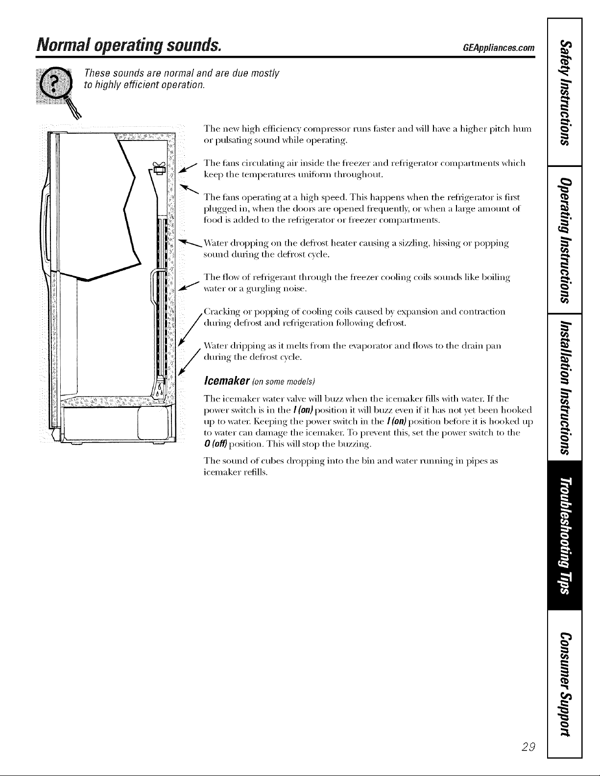
Normaloperatingsounds.
These sounds are normal and are due mostly
to highly efficient operation.
The new high efficiency c()mpressor runs tipster and will haxe a higher pitch lmm
or I)ulsafing, sound while oi)erating.
The thns circtflafing air inside the fl'eezer and refi_igerator coml)artments which
kee I) the temperatm'es unifi)I_n throtlghotlt.
The tans operating at a high speed. This happens when the refl_igerator is fi_t
I)lugged,, in when the (loo_ are I° )ened f'e(luentl_ or when a large, amount of
food is added to the reli_igerator or ti'eezer compartments.
_4]_ter dropping on the defl'ost heater causing a sizzling, hissing or popping
sound dtwing the defrost cycle.
The flow of reti_igerant through the ti'eezer cooling coils sotmds like boiling
water or a gurgling noise.
(hwing def'ost and refrigeration following deft'est.
GEPppliances.com
of cooling coils caused by expansion and contraction
_&_ter dripping as it melts from the exaporator and flows to the drain pan
(hwing the defrost c_cle.
Icemaker (onsomemodels)
The icemaker water valve will buzz when the icemaker flls with _:_te_: If the
power switch is in the I (on) position it will buzz even if it has not yet been hooked
up to water: Keeping the power switch in the I (on} position beii)re it is hooked up
to water can damage the icemake_: To prevent this, set the power switch to the
0 (off} position. This will stop the buzzing.
The sotmd of cubes dropping into the bin and water rtmning in pipes as
icemaker refills.
29
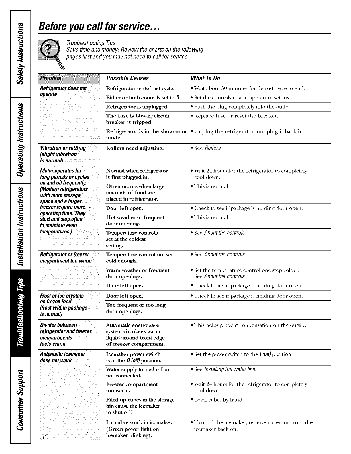
Beforeyoucall forservice...
Troubleshooting -tips
Save time and money/. Review the charts on the following
pages first and you may not need to call for service.
Possible Causes What To Do
Refrigerator does not Refrigerator in defrost cycle. * Wait ab(mt 30 minutes fi w (lefl_()st cycle to end.
Either or both controls set to 0. * Set tile controls to a temperature setting.
Refrigerator is unplugged. * Push tile plug completely into the outlet.
The fuse is blown/cireult * Replace fl/se or reset the breaker.
breaker is tripped.
Refrigerator is in the showroom * Uuph/g the refrigerator and plug it back in.
mode.
Vibration orrattling Rollers need adjusting. * See Rollers.
(slight vibration
is normal)
Motor operates for Normal when refrigerator * Wait 24 hom_ for the refrigerator to (ompletely
Iongperiods or cycles is f'test plugged in. cool down.
on and off frequently.
(Modern refrigerators mnom_ts of food are
with more storage
space and a larger placed in refrigerator.
freezer require more Door left open. * Check to see if package is holding door open.
operating time. They.
MartandMop often Hot weather or frequent * This is uom/al.
to maintain even door openings.
temperatures.) Temperature controls * See About the controls.
Refrigerator or freezer Temperature control not set • See About the controls.
compartment too warm cold enough.
Often occurs when large * This is uom_al.
set at the coldest
setting.
Warm weather or frequent • Set the temperatm'e c(mtrol one step col(le_:
door openhl_. See About the controls.
Door left open. • Check to see if package is holding door open.
From orice crystals Door left open. • Check to see it package is holding door open.
on frozen food
(from within package Too frequent or too long
is normal) door ope*m_.
Divider between Automatic energy saver • This helps preveut coudeusatioi_ on the outside.
refrigerator and freezer system circulates warm
compartments liquid around front edge
feels warm of freezer compartment.
Automatic icemaker lcemaker power swhch • Set the power switch to the I (on) position.
does not work is in the 0 (off) position.
Water supply turned off or • See Installing the water line.
not comlected.
Freezer compartment • Wait 24 hotu_ fin" the refl'igerator to completely
too Warln. cool dowu.
Piled up cubes in the storage • I,evel cubes by hand.
bin cause the icemaker
to shut off.
Ice cubes stuck in icemaker.
(Green power light on
_0 icemaker blinking).
• Turn off the icemakei, remove cubes and ttwn the
icelnaker back on.
 Loading...