

GE PSS25NGNACC, PSF26NGNAWW, PSS25, PSS25NGN, PSS29 User Manual
...
GEAppliances.com
Refrigerators
Profile Side by Side
200D2600P018 49-60195 02-02 JR
La section française commence à la page 42
La sección en español empieza en la página 78
Safety Instructions . . . . . . . . . . .2–4
Operating Instructions
Additional Features . . . . . . . . . . . .12
Automatic Icemaker . . . . . . . . . . .14
Care and Cleaning . . . . . . . . . .16, 17
Crispers and Pans . . . . . . . . . . . . .13
CustomCool
™
. . . . . . . . . . . . . . . .7, 8
Ice and Water Dispenser . . . . .15, 16
Refrigerator Doors . . . . . . . . . . . .12
Replacing the Light Bulbs . . . . . . .18
Shelves and Bins . . . . . . . . . . .10, 11
Temperature Controls . . . . . . . . . . .5
TurboCool
™
. . . . . . . . . . . . . . . . . . .6
Water Filter . . . . . . . . . . . . . . . . . . .9
Installation Instructions
Preparing to Install
the Refrigerator . . . . . . . . . . . .24, 25
Removing and
Replacing Doors . . . . . . . . . . . . . .23
Trim Kits and Panels . . . . . . . .19–22
Water Line Installation . . . . . .26–30
Troubleshooting Tips . . . . . . .32–34
Normal Operating Sounds . . . . . .31
Consumer Support
Consumer Support . . . . .Back Cover
Performance Data Sheet . . . . . . . .37
Product Registration . . . . . . . .39, 40
State of California Water
Treatment Device Certificate . . . . .38
Warranty (Canadian) . . . . . . . . . . .35
Warranty (U.S.) . . . . . . . . . . . . . . .36
Réfrigérateurs
Profile Côte à Côte
Refrigeradores
Profile Lado a Lado
Models 23, 25, 26, 27 and 29
Write the model and serial numbers here:
Model # __________________________
Serial # __________________________
Find these numbers on a label inside
the refrigerator compartment at the
top on the right side.
Owner’s Manual
and Installation
Manuel d’utilisation
et d’installation
Manual del propietario
e instalación
Consumer Support Troubleshooting Tips
Operating Instructions
Safety InstructionsInstallation Instructions
2
IMPORTANT SAFETY INFORMATION.
READ ALL INSTRUCTIONS BEFORE USING.
WARNING!
Use this appliance only for its intended purpose as described in this Owner’s Manual.
SAFETY PRECAUTIONS
When using electrical appliances, basic safety precautions should be followed, including the following:
■
■This refrigerator must be properly installed
and located in accordance with the Installation
Instructions before it is used.
■
■Do not allow children to climb, stand or hang
on the shelves in the refrigerator. They could
damage the refrigerator and seriously injure
themselves.
■
■Do not touch the cold surfaces in the freezer
compartment when hands are damp or wet. Skin
may stick to these extremely cold surfaces.
■
■Do not store or use gasoline or other flammable
vapors and liquids in the vicinity of this or any
other appliance.
■
■In refrigerators with automatic icemakers,
avoid contact with the moving parts of the
ejector mechanism, or with the heating element
located on the bottom of the icemaker. Do not
place fingers or hands on the automatic
icemaking mechanism while the refrigerator
is plugged in.
■
■Keep fingers out of the “pinch point” areas;
clearances between the doors and between
the doors and cabinet are necessarily small.
Be careful closing doors when children are
in the area.
■
■Unplug the refrigerator before cleaning and
making repairs.
NOTE: We strongly recommend that any servicing be
performed by a qualified individual.
■
■Setting either or both controls to
0 (off)
does not
remove power to the light circuit.
■
■Do not refreeze frozen foods which have
thawed completely.
■
■Always clean the
CustomCool
™
Tray after thawing
food.
Consumer SupportTroubleshooting Tips
Operating Instructions
Safety Instructions Installation Instructions
GEAppliances.com
PROPER DISPOSAL OF THE REFRIGERATOR
Child entrapment and suffocation are not problems
of the past. Junked or abandoned refrigerators are
still dangerous…even if they will sit for “just a few
days.” If you are getting rid of your old refrigerator,
please follow the instructions below to help prevent
accidents.
Before You Throw Away Your Old Refrigerator
or Freezer:
■Take off the doors.
■Leave the shelves in place so that children may
not easily climb inside.
CFC Disposal
Your old refrigerator may have a cooling system
that used CFCs (chlorofluorocarbons). CFCs are
believed to harm stratospheric ozone.
If you are throwing away your old refrigerator, make
sure the CFC refrigerant is removed for proper
disposal by a qualified servicer. If you intentionally
release this CFC refrigerant you can be subject to
fines and imprisonment under provisions of
environmental legislation.
USE OF EXTENSION CORDS
Because of potential safety hazards under certain conditions, we strongly recommend against the use
of an extension cord.
However, if you must use an extension cord, it is absolutely necessary that it be a UL-listed (in the United
States) or a CSA-listed (in Canada), 3-wire grounding type appliance extension cord having a grounding
type plug and outlet and that the electrical rating of the cord be 15 amperes (minimum) and 120 volts.
DANGER! RISK OF CHILD ENTRAPMENT
3
4
Consumer Support Troubleshooting Tips
Operating Instructions
Safety InstructionsInstallation Instructions
IMPORTANT SAFETY INFORMATION.
READ ALL INSTRUCTIONS BEFORE USING.
WARNING!
HOW TO CONNECT ELECTRICITY
Do not, under any circumstances, cut or remove the third (ground) prong from the power cord. For
personal safety, this appliance must be properly grounded.
The power cord of this appliance is equipped
with a 3-prong (grounding) plug which mates
with a standard 3-prong (grounding) wall outlet
to minimize the possibility of electric shock hazard
from this appliance.
Have the wall outlet and circuit checked by a
qualified electrician to make sure the outlet is
properly grounded.
If the outlet is a standard 2-prong outlet, it is your
personal responsibility and obligation to have it
replaced with a properly grounded 3-prong wall
outlet.
The refrigerator should always be plugged into its
own individual electrical outlet which has a voltage
rating that matches the rating plate.
This provides the best performance and also
prevents overloading house wiring circuits which
could cause a fire hazard from overheated wires.
Never unplug your refrigerator by pulling on the
power cord. Always grip plug firmly and pull straight
out from the outlet.
Repair or replace immediately all power cords that
have become frayed or otherwise damaged. Do not
use a cord that shows cracks or abrasion damage
along its length or at either end.
When moving the refrigerator away from the
wall, be careful not to roll over or damage the
power cord.
USE OF ADAPTER PLUGS
(Adapter plugs not permitted in Canada)
Because of potential safety hazards under certain conditions, we strongly recommend against
the use of an adapter plug.
However, if you must use an adapter, where local
codes permit, a
temporary connection
may be made
to a properly grounded 2-prong wall outlet by use
of a UL-listed adapter available at most local
hardware stores.
The larger slot in the adapter must be aligned with
the larger slot in the wall outlet to provide proper
polarity in the connection of the power cord.
When disconnecting the power cord from the
adapter, always hold the adapter in place with one
hand while pulling the power cord plug with the
other hand. If this is not done, the adapter ground
terminal is very likely to break with repeated use.
If the adapter ground terminal breaks,
DO NOT
USE
the refrigerator until a proper ground has
been established.
Attaching the adapter ground terminal to a wall outlet
cover screw does not ground the appliance unless the
cover screw is metal, and not insulated, and the wall
outlet is grounded through the house wiring. You should
have the circuit checked by a qualified electrician to make
sure the outlet is properly grounded.
READ AND FOLLOW THIS SAFETY INFORMATION CAREFULLY.
SAVE THESE INSTRUCTIONS
Consumer SupportTroubleshooting Tips
Operating InstructionsSafety Instructions
Installation Instructions
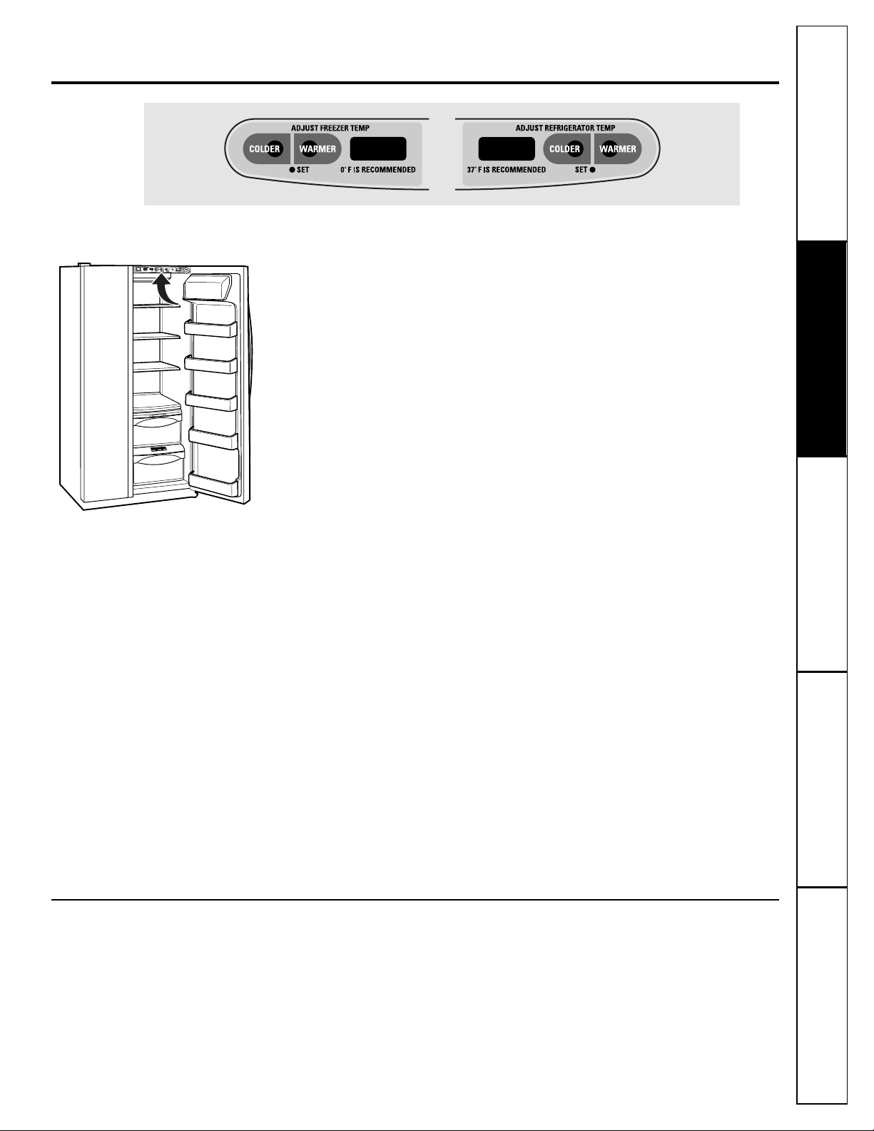
About the temperature controls.
GEAppliances.com
The temperature controls are preset in the factory at 37°F for the
refrigerator compartment and 0°F for the freezer compartment. Allow
24 hours for the temperature to stabilize to the preset recommended
settings.
The temperature controls can display both the SET temperature
as well as the actual temperature in the refrigerator and freezer.
The actual temperature may vary slightly from the SET temperature
based on usage and operating environment.
Setting either or both controls to OFF stops cooling in both the freezer
and refrigerator compartments, but does not shut off electrical power
to the refrigerator.
NOTE: The refrigerator is shipped with protective film covering the
temperature controls. If this film was not removed during installation,
remove it now.
The Performance Air-Flow System is designed to
maximize temperature control in the refrigerator
and freezer compartments. This unique special
feature consists of the Air Tower along the back
wall of the refrigerator and the Air Tunnel on the
bottom portion of the freezer rear wall. Placing food
in front of the louvers on these components will not
affect performance. Although the Air Tower and
the Air Tunnel can be removed, doing so will affect
temperature performance. (For removal
instructions, on-line, 24 hours a day, contact us at
GEAppliances.com or call 800.GE.CARES. In
Canada, contact us at geappliances.ca or call
1.800.361.3400.)
Performance Air Flow System
To change the temperature,
press and release the
WARMER
or
COLDER
pad. The
SET
light will come
on and the display will show the set temperature.
To change the temperature, tap either the
WARMER
or
COLDER
pad until the desired
temperature is displayed. Refrigerator temperatures
can be adjusted between 34°F and 44°F and the
freezer temperatures can be adjusted between
–6°F and +6°F.
Once the desired temperature has been set,
the temperature display will return to the actual
refrigerator and freezer temperatures after 5
seconds. Several adjustments may be required.
Each time you adjust controls, allow 24 hours for the
refrigerator to reach the temperature you have set.
To turn the cooling system off,
tap the
WARMER
pad
for either the refrigerator or the freezer until the
display shows
OFF. To turn the unit back on,
press the
COLDER
pad for either the refrigerator or freezer.
The
SET
light will illuminate on the side you
selected. Then press the
COLDER
pad again (on the
side where the
SET
light is illuminated) and it will
go to the preset points of
0°F
for the freezer and
37°F
for the refrigerator. Setting either or both
controls to
OFF
stops cooling in both the freezer
and refrigerator compartments, but does not shut
off electrical power to the refrigerator.
5
6
About TurboCool.
™
How it Works
TurboCool
rapidly cools the refrigerator
compartment in order to more quickly
cool foods. Use
TurboCool
when adding a
large amount of food to the refrigerator
compartment, putting away foods after they
have been sitting out at room temperature
or when putting away warm leftovers. It can
also be used if the refrigerator has been
without power for an extended period.
Once activated, the compressor will turn on
immediately and the fans will cycle on and
off at high speed as needed for eight hours.
The compressor will continue to run until
the refrigerator compartment cools to
approximately 34°F (1°C), then it will cycle
on and off to maintain this setting. After 8
hours, or if
TurboCool
is pressed again, the
refrigerator compartment will return to
the original setting.
How to Use
Press
TurboCool
. The refrigerator
temperature display will show TC.
After
TurboCool
is complete, the
refrigerator compartment will return
to the original setting.
NOTES:
The refrigerator temperature
cannot be changed during
TurboCool
.
The freezer temperature is not
affected during
TurboCool
.
When opening the refrigerator
door during
TurboCool
, the fans
will continue to run if they have
cycled on.
Consumer Support Troubleshooting Tips
Operating Instructions
Safety InstructionsInstallation Instructions
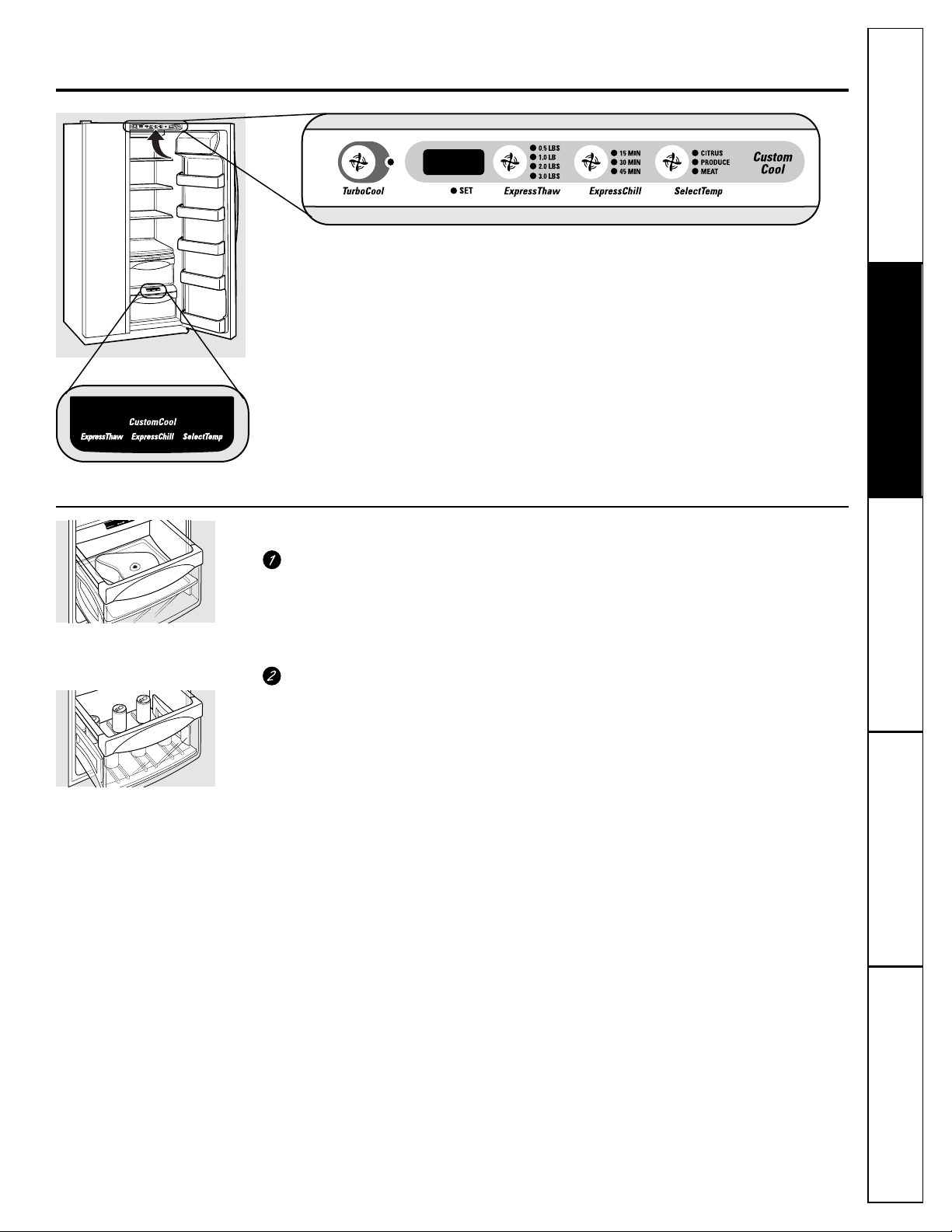
Empty the pan. Place the Chill/Thaw
tray in the pan with the metal plate
facing down to chill and store items, or
with the metal plate facing up to thaw
items. Place the items on the tray and
close the pan completely.
Select the
ExpressThaw,™ExpressChill
™
or
SelectTemp
™
pad. The display and
SET
light will come on. Tap the pad
until the light appears next to the
desired setting. Use the chart to
determine the best setting to use.
■ To stop a feature before it is
finished, tap that feature’s pad
until no options are selected and
the display is off.
■ During
ExpressThaw
™
and
ExpressChill,
™
the display on the
controls will count down the time
in the cycle.
■ After the
ExpressThaw
™
cycle is
complete, the pan will reset to the
MEAT
setting (31°F) to help preserve
thawed items until they are used.
■ The displayed actual temperature of
the
CustomCool
pan may vary slightly
from the
SET
temperature based on
usage and operating environment.
NOTE:
For food safety reasons, it is
recommended that foods be wrapped
in plastic wrap when using
ExpressThaw.
™
This will help contain meat juices and
improve thawing performance.
7
About CustomCool™.
GEAppliances.com
The
CustomCool
™
feature is a system of
dampers, a fan, a temperature thermistor
and a heater. Depending on the function
selected, a combination of these will be
used to quickly chill items, thaw items or
hold the pan at a specific temperature.
The pan is tightly sealed to prevent the pan’s
temperature from causing temperature
fluctuations in the rest of the refrigerator.
The controls for this pan are located at the
top of the refrigerator with the temperature
controls.
How to Use
How it Works
ExpressThaw
™
ExpressChill
™
Consumer SupportTroubleshooting Tips
Operating InstructionsSafety Instructions
Installation Instructions
8
About CustomCool™.
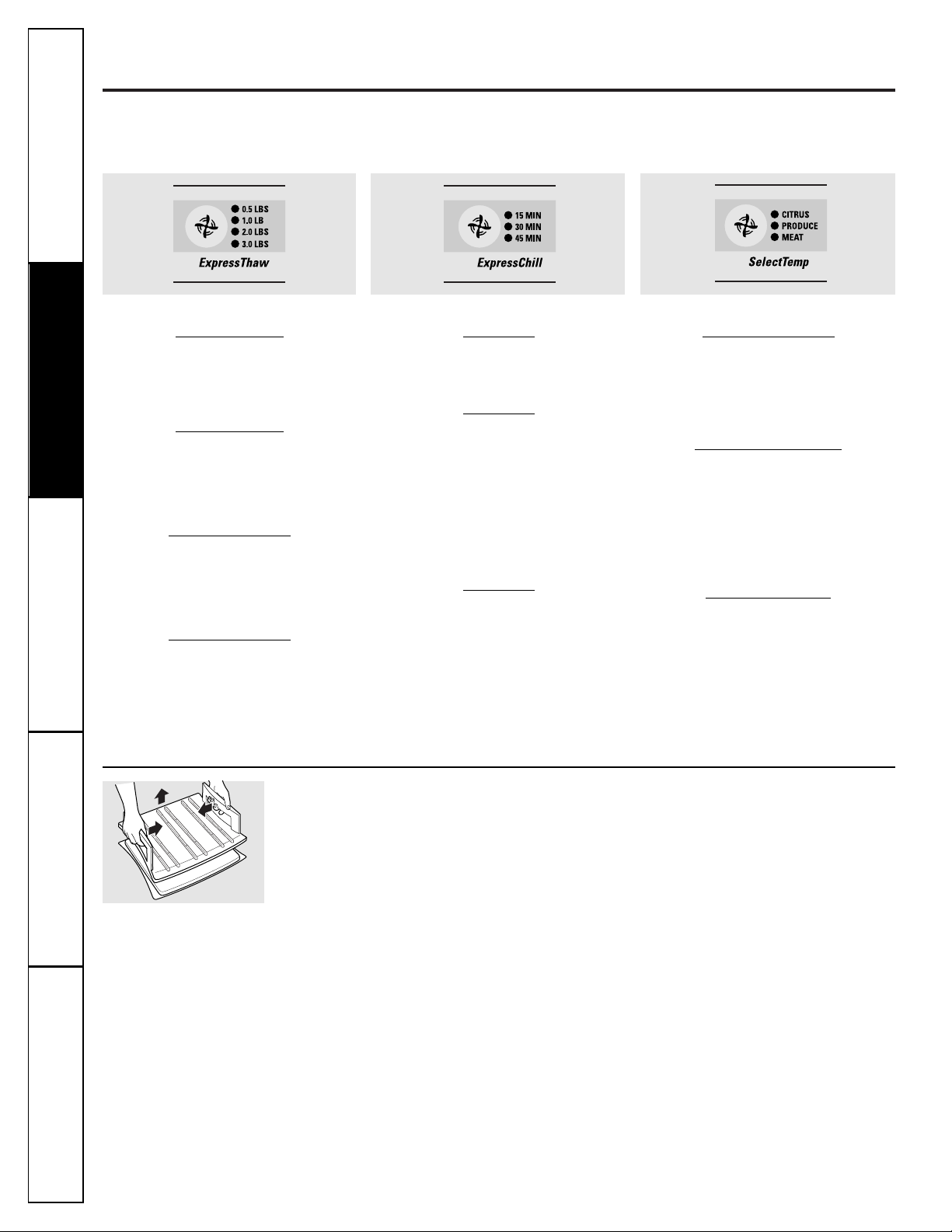
CustomCool™Chart
NOTE: Results may vary depending on packaging, starting temperature and other food traits.
To clean the Chill/Thaw tray,
disassemble the
metal tray from the plastic stand by lightly
pushing in on the handles of the plastic
stand and removing the metal tray. Both
the metal tray and the plastic stand are
dishwasher safe.
To reassemble the tray,
place the plastic
stand upside down (handles on bottom) on
a solid surface. Place the metal plate on top
of the stand matching up the curved side of
the plate with the curved side of the stand.
Insert one side of the plate into the notches
on the stand. Push in on the handle on the
other side of the stand while pushing that
end of the plate down and into place. You
should hear the plate “click” into place.
About the CustomCool™Pan Rack and Tray
Disassembling the
Chill/Thaw
tray
0.5 Lb. (4 hours)
■ Hamburger Patties (0.5 lb)
■ Individually Wrapped
Filet Mignon (0.5 lb)
1.0 Lb. (6 hours)
■ Chicken Breasts (1.0 lb)
■ Ground Beef (1.0 lb)
■ Steak (1.0 lb)
2.0 Lbs. (10 hours)
■ Chicken Breasts (2.0 lbs)
■ Ground Beef (2.0 lbs)
■ Steak (2.0 lbs)
3.0 Lbs. (12 hours)
■ Chicken Breasts (3.0 lbs)
■ Ground Beef (3.0 lbs)
■ Steak (3.0 lbs)
15 Minutes
■ 1 Beverage Can (12 oz)
■ 2 Small Juice Boxes (6–8 oz each)
30 Minutes
■ 2 to 6 Beverage Cans (12 oz each)
■ 2 Plastic 20 oz Bottles of Beverage
■ 4 to 6 Small Juice Boxes
(6–8 oz each)
■ 3 Foil Juice Packets
■ Wine (750 ml bottle)
45 Minutes
■ 2 Liter of Beverage
■ 1/2 Gallon of Juice
■ Gelatin–1 package
Citrus Setting (43°F)
■ Oranges, Lemons, Limes,
Pineapple, Cantaloupe
■ Beans, Cucumbers, Tomatoes,
Peppers, Eggplant, Squash
Produce Setting (35°
F)
■ Strawberries, Raspberries, Kiwifruit,
Pears, Cherries, Blackberries,
Grapes, Plums, Nectarines, Apples
■ Asparagus, Broccoli, Corn,
Mushrooms, Spinach, Cauliflower,
Kale, Green Onion, Beets, Onions
Meat Setting (31°F)
■ Raw Meat, Fish and Poultry
Consumer Support Troubleshooting Tips
Operating Instructions
Safety InstructionsInstallation Instructions
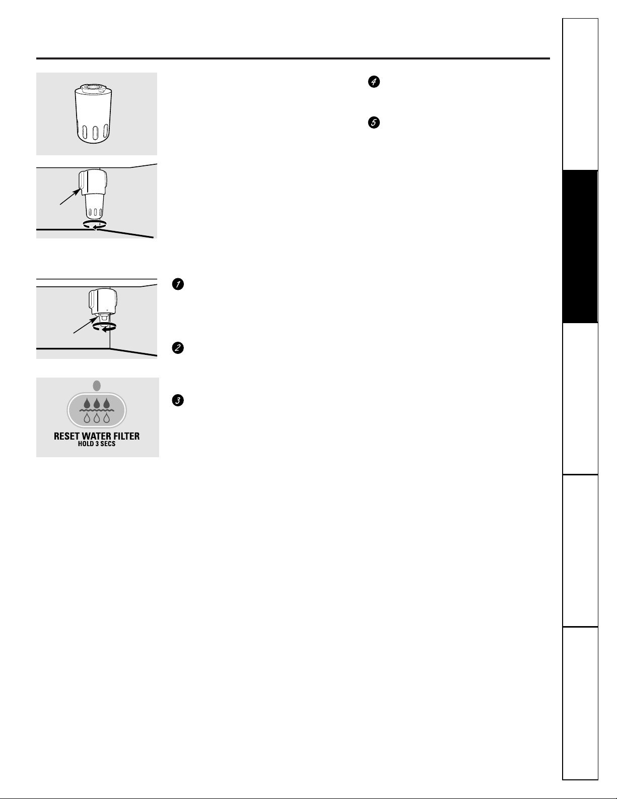
About the water filter.
(on some models)
GEAppliances.com
9
Water Filter Cartridge
The water filter cartridge is located in the
back upper right corner of the refrigerator
compartment.
When to Replace the Filter
There is a replacement indicator light for
the water filter cartridge on the dispenser.
This light will turn orange to tell you that
you need to replace the filter soon.
The filter cartridge should be replaced
when the replacement indicator light turns
red or if the flow of water to the dispenser
or icemaker decreases.
Installing the Filter Cartridge
If you are replacing the cartridge, first
remove the old one by slowly turning
it to the left.
Do not
pull down on the
cartridge. A small amount of water may
drip down.
Fill the replacement cartridge with
water from the tap to allow for better
flow from the dispenser immediately
after installation.
Lining up the arrow on the cartridge
and the cartridge holder, place the
top of the new cartridge up inside
the holder.
Do not
push it up into
the holder.
Slowly turn it to the right until the filter
cartridge stops.
DO NOT OVERTIGHTEN.
As you turn the cartridge, it will
automatically raise itself into position.
Cartridge will rotate about 1/4 turn.
Run water from the dispenser for
3 minutes (about 11⁄2 gallons) to clear
the system and prevent sputtering.
Press and hold the
RESET WATER FILTER
pad on the dispenser for 3 seconds.
NOTE:
A newly-installed water filter
cartridge may
cause water to spurt
from
the dispenser.
Filter Bypass Plug
You must use the filter bypass plug
when a replacement filter cartridge is not
available. The dispenser and the icemaker
will not operate without the filter or filter
bypass plug.
Replacement Filters:
To order additional filter cartridges
in the United States, visit our Website,
GEAppliances.com, or call
GE Parts and Accessories, 800.626.2002.
GWF
Suggested Retail $34.95 USD
Customers in Canada should consult
the yellow pages for the nearest Camco
Service Center.
Place the top of the cartridge up
inside the cartridge holder and
slowly turn it to the right.
Filter Bypass Plug
Cartridge
Holder
Consumer SupportTroubleshooting Tips
Operating InstructionsSafety Instructions
Installation Instructions
Consumer Support Troubleshooting Tips
Operating Instructions
Safety InstructionsInstallation Instructions
10
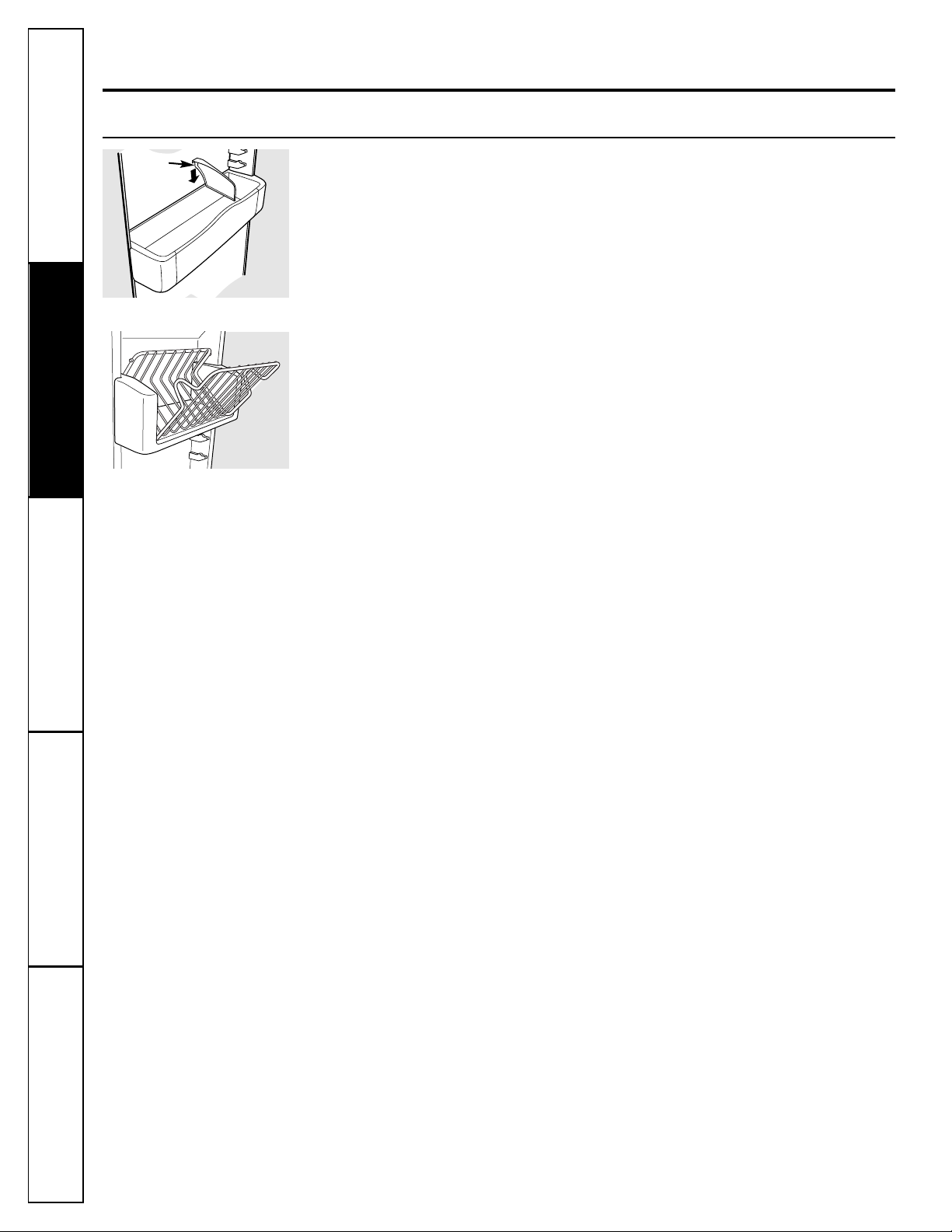
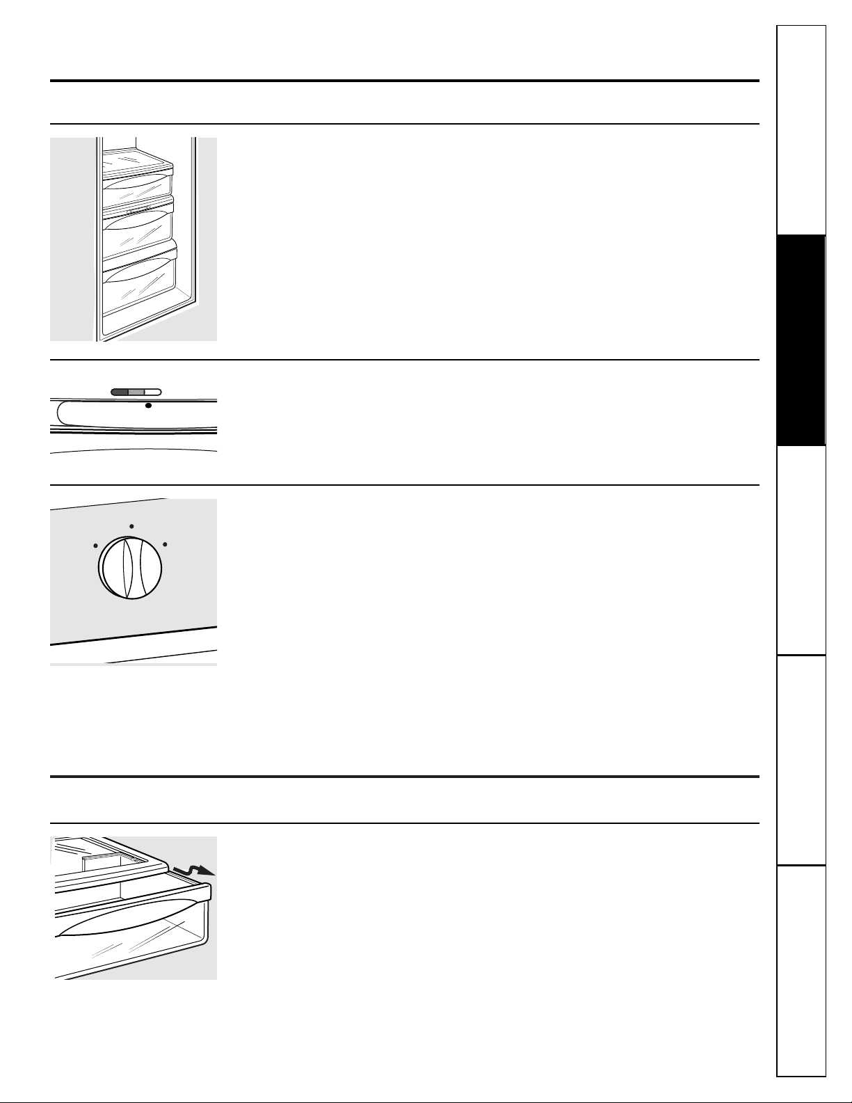
About the shelves and bins.
Refrigerator Door Bins and Freezer Door Tilt-Out Bins
Large Bins
The larger refrigerator door bins and
freezer tilt-out door bins are adjustable.
To remove:
Lift the front of the bin straight
up, then lift up and out.
To replace or relocate:
Engage the back side
of the bin in the molded supports of the
door. Then push down on the front of the
bin. Bin will lock in place.
Small Bins
To remove:
Lift the front of the bin straight
up then out.
To replace:
Position the bin above the
rectangular molded supports on the door.
Then slide the bin down onto the support
to lock it in place.
The snugger
helps prevent tipping, spilling
or sliding of small items stored on the door
shelf. Place a finger on either side of the
snugger near the rear and move it back
and forth to fit your needs.
Not all features are on all models.
Refrigerator bin
Freezer tilt-out bin
Snugger

11
GEAppliances.com
Not all features are on all models.
QuickSpace™Shelf
This shelf splits in half and slides under
itself for storage of tall items on the shelf
below.
This shelf can be removed and replaced
or relocated just like Slide-Out Spillproof
Shelves.
On some models, this shelf can not be used
in the lowest position.
Slide-Out Spillproof Shelf
The slide-out spillproof shelf allows you
to reach items stored behind others. The
special edges are designed to help prevent
spills from dripping to lower shelves.
To remove:
Slide the shelf out until it reaches the stop,
then press down on the tab and slide the
shelf straight out.
To replace or relocate:
Line the shelf up with the supports and
slide it into place. The shelf can be
repositioned when the door is at 90° or
more. To reposition the shelf, slide the shelf
past the stops and angle downward. Slide
shelf down to the desired position, line up
with the supports and slide into place.
Make sure you push the shelves all the way back
in before you close the door.
Slide-Out Freezer Shelves
To remove,
slide out to the
stop
position,
lift the front past the stop position, and
slide out.
Make sure you push the shelves all the way back
in before you close the door.
Freezer Baskets
To remove,
push the basket all the way to the
back of the freezer. Lift up until the back
pins are disengaged. Lift the entire basket
up and pull out.
The divider
can be used to organize food
packages. For large packages, simply fold
down the divider.
Make sure you push the baskets all the way back
in before you close the door.
Press tab and pull shelf
forward to remove
Fixed Freezer Shelves
To remove,
lift the shelf up at the left side
and then bring the shelf out.
Consumer SupportTroubleshooting Tips
Operating Instructions
Safety Instructions Installation Instructions
Divider
Consumer Support Troubleshooting Tips
Operating Instructions
Safety InstructionsInstallation Instructions
About the additional features.
12
Not all features are on all models.
Removable Beverage Rack
The beverage rack is designed to hold
a bottle on its side. It can be attached to
any slide-out shelf.
To install:
Line up the large part of the slots on
the top of the rack with the tabs under
the shelf.
Then slide the rack back to lock it
in place.
About the refrigerator doors.
Refrigerator Doors
The refrigerator doors may feel different
than the ones you are used to. The special
door opening/closing feature makes sure
the doors close all the way and are securely
sealed.
When opening and closing the door you
will notice a
stop
position. If the door is
opened past this
stop
point, the door will
remain open to allow you to load and
unload food more easily. When the door
is only partially open, it will automatically
close.
The resistance you feel at the
stop
position will be reduced as the door
is loaded with food.
When the door is only partially open,
it will automatically close.
Beyond this stop the door will stay open.
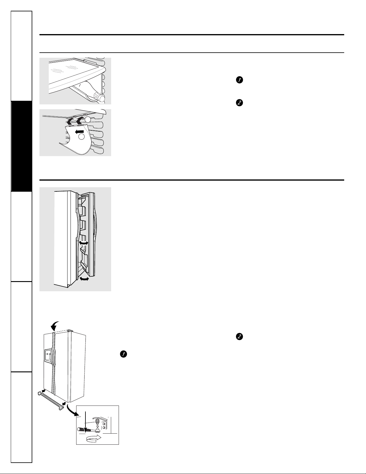
Door Alignment
If doors are uneven, adjust the refrigerator
door.
Using a 7/16″ socket wrench, turn the
door adjusting screw to the right to
raise the door, to the left to lower it.
(A nylon plug, imbedded in the
threads of the pin, prevents the pin
from turning unless a wrench is used.)
After one or two turns of the wrench,
open and close the refrigerator door
and check the alignment at the top of
the doors.
To remove the base
grille, open the doors,
remove the screw at
each end of the base
grille and then pull
the grille straight out.
7/16″Socket Wrench
Raise
1
2
About the crispers and pans.
GEAppliances.com
13
About crisper removal.
Not all features are on all models.
Crisper Removal
Crispers can easily be removed by pulling
the drawer straight out and lifting the
drawer up and over the
stop
location.
If the door prevents you from taking out
the drawers, first try to remove the door
bins. If this does not offer enough
clearance, the refrigerator will need to
be rolled forward until the door opens
enough to slide the drawers out. In some
cases, when you roll the refrigerator out,
you will need to move the refrigerator
to the left or right as you roll it out.
Not all features are on all models.
Fruit and Vegetable Crispers
Excess water that may accumulate in the
bottom of the drawers should be wiped dry.
On some models,
the bottom drawer has
a cover that slides back as the drawer is
opened. This allows full access to the
drawer. As the drawer is closed, the cover
will slide forward into its original position.
Adjustable Humidity Crispers
Slide the control all the way to the
HI
setting
to provide high humidity recommended for
most vegetables.
Slide the control all the way to the
LO
setting to provide lower humidity levels
recommended for most fruits.
Convertible Meat Pan
The convertible meat pan has its own cold
air duct to allow a stream of cold air from
the freezer compartment to flow to the pan.
The variable temperature control
regulates
the air flow from the Climate Keeper.
Set the control to the
coldest
setting to
store fresh meats.
Set the control to
cold
to convert the pan
to normal refrigerator temperature and
provide extra vegetable storage space. The
cold air duct is turned off. Variable settings
between these extremes can be selected.
Consumer SupportTroubleshooting Tips
Operating Instructions
Safety Instructions Installation Instructions
HI LO
D
L
O
C
C
O
L
D
E
S
T
About the automatic icemaker.
Consumer Support Troubleshooting Tips
Operating Instructions
Safety InstructionsInstallation Instructions
14
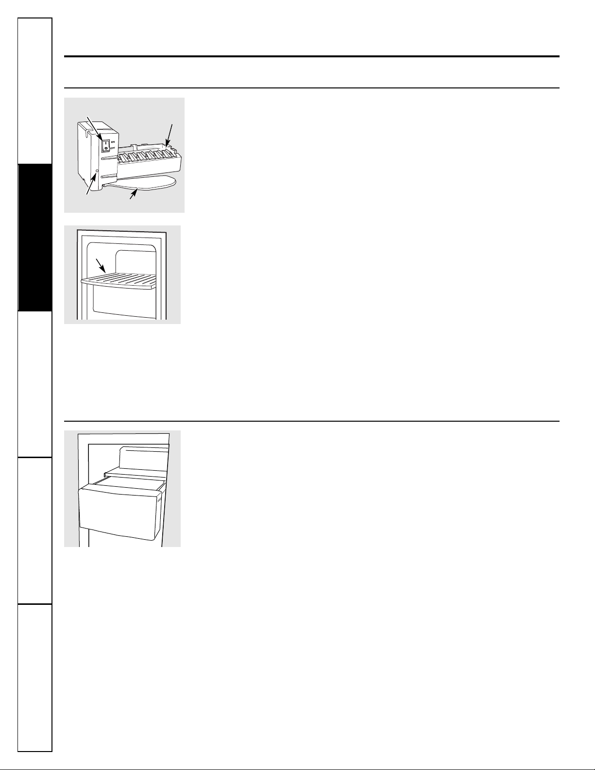
Automatic Icemaker
The icemaker will produce seven cubes
per cycle—approximately 100–130 cubes
in a 24-hour period, depending on freezer
compartment temperature, room
temperature, number of door openings
and other use conditions.
If the refrigerator is operated before the
water connection is made to the icemaker,
set the power switch in the
O (off)
position.
When the refrigerator has been connected
to the water supply, set the power switch to
the
l (on)
position.
The icemaker will fill with water when it
cools to 15°F (–10°C). A newly installed
refrigerator may take 12 to 24 hours to begin
making ice cubes.
You will hear a buzzing sound each time
the icemaker fills with water.
Throw away the first few batches of ice to
allow the water line to clear.
Be sure nothing interferes with the sweep
of the feeler arm.
When the bin fills to the level of the feeler
arm, the icemaker will stop producing
ice. It is normal for several cubes to be
joined together.
If ice is not used frequently, old ice cubes
will become cloudy, taste stale and shrink.
NOTE: In homes with lower-than-average water
pressure, you may hear the icemaker cycle multiple
times when making one batch of ice.
A newly installed refrigerator may take 12 to 24 hours to begin making ice.
Pull the upper freezer shelf straight
out to access the icemaker. Always
be sure to replace the shelf. The
shelf can be used for storage.
Ice Storage Drawer
To access ice,
pull the drawer forward.
To remove the drawer,
pull it straight out and
lift it past the
stop
location.
Icemaker
Feeler Arm
Power
Switch
Green
Power Light
Ice Drawer
Ice Drawer
Shelf
Important Facts About Your Dispenser
■Do not add ice from trays or bags to
the storage drawer. It may not crush or
dispense well.
■Avoid overfilling glass with ice and use of
narrow glasses. Backed-up ice can jam the
chute or cause the door in the chute to
freeze shut. If ice is blocking the chute,
poke it through with a wooden spoon.
■Beverages and foods should not be
quick-chilled in the ice storage drawer.
Cans, bottles or food packages in the
storage drawer may cause the icemaker
or auger to jam.
■To keep dispensed ice from missing
the glass, put the glass close to, but not
touching, the dispenser opening.
■Some crushed ice may be dispensed
even though you selected
CUBED ICE.
This happens occasionally when a few
cubes accidentally get directed to
the crusher.
■After crushed ice is dispensed, some
water may drip from the chute.
■Sometimes a small mound of snow will
form on the door in the ice chute. This
condition is normal and usually occurs
when you have dispensed crushed ice
repeatedly. The snow will eventually
evaporate.
15
About the ice and water dispenser.
(on some models)
GEAppliances.com
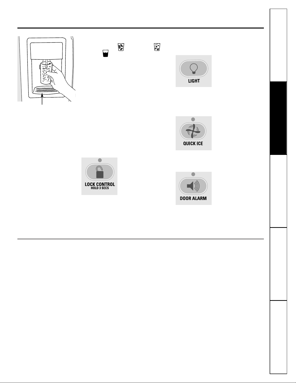
To Use the Dispenser
Select
CUBED ICE , CRUSHED ICE
or
WATER .
Press the glass gently against the top of
the dispenser cradle.
The spill shelf is not self-draining.
To reduce water spotting, the shelf and
its grille should be cleaned regularly.
If no water is dispensed when the refrigerator is
first installed, there may be air in the water line
system. Press the dispenser arm for at least two
minutes to remove trapped air from the water
line and to fill the water system. To flush out
impurities in the water line, throw away the first
six glassfuls of water.
CAUTION: Never put fingers or any other
objects into the ice crusher discharge opening.
Locking the Dispenser
Press the
LOCK CONTROL
pad for 3 seconds to
lock the dispenser and
control panel. To
unlock, press and
hold the pad again
for 3 seconds.
Dispenser Light
This pad turns the
night
light
in the dispenser
on and off. The light
also comes on when
the dispenser cradle is
pressed. If this light
burns out, it should be
replaced with a 6 watt
12V maximum bulb.
Quick Ice
When you need ice
in a hurry, press this
pad to speed up ice
production. This will
increase ice production
for the following
48 hours or until you
press the pad again.
Door Alarm
To set the alarm, press
this pad until the
indicator light comes
on. This alarm will
sound if either door is
open for more than
3 minutes. The light
goes out and the
beeping stops when
you close the door.
Spill Shelf
Consumer SupportTroubleshooting Tips
Operating InstructionsSafety Instructions
Installation Instructions
Consumer Support Troubleshooting Tips
Operating Instructions
Safety InstructionsInstallation Instructions
16
Care and cleaning of the refrigerator.
Cleaning the Outside
The dispenser drip area,
beneath the grille,
should be wiped dry. Water left in this area
may leave deposits. Remove the deposits by
adding undiluted vinegar to the well. Soak
until the deposits disappear or become
loose enough to rinse away.
The dispenser cradle
. Before cleaning, lock
the dispenser by pressing and holding the
LOCK CONTROL
pad for 3 seconds. Clean
with warm water and baking soda
solution–about a tablespoon (15 ml) of
baking soda to a quart (1 liter) of water.
Rinse thoroughly and wipe dry.
The door handles and trim.
Clean with
a cloth dampened with soapy water.
Dry with a soft cloth.
The stainless steel panels and door handles
(on some models) can be cleaned with a
commercially available stainless steel
cleaner such as Stainless Steel Magic.
™
Stainless Steel Magic is available at Ace, True
Value, Servistar, HWI and other leading
stores. It is also available through GE Parts
and Accessories, 800.626.2002. Order part
number WX10X15.
Do not use appliance wax or polish on the
stainless steel.
Keep the outside clean.
Wipe with a clean
cloth lightly dampened with kitchen
appliance wax or mild liquid dish detergent.
Dry and polish with a clean, soft cloth.
Do not wipe the refrigerator with a soiled dish
cloth or wet towel. These may leave a residue
that can erode the paint. Do not use scouring
pads, powdered cleaners, bleach or cleaners
containing bleach because these products can
scratch and weaken the paint finish.
Cleaning the Inside
To help prevent odors,
leave an open box of
baking soda in the fresh food and freezer
compartments.
Unplug the refrigerator before cleaning.
If this
is not practical, wring excess moisture out
of sponge or cloth when cleaning around
switches, lights or controls.
Use warm water and baking soda solution–
about a tablespoon (15 ml) of baking soda
to a quart (1 liter) of water. This both
cleans and neutralizes odors. Rinse and
wipe dry.
Use of any cleaning solution other than that
which is recommended, especially those that
contain petroleum distillates, can crack or
damage the interior of the refrigerator.
Avoid cleaning cold glass shelves with hot water
because the extreme temperature difference
may cause them to break. Handle glass shelves
carefully. Bumping tempered glass can cause
it to shatter.
Do not wash any plastic refrigerator parts in the
dishwasher.
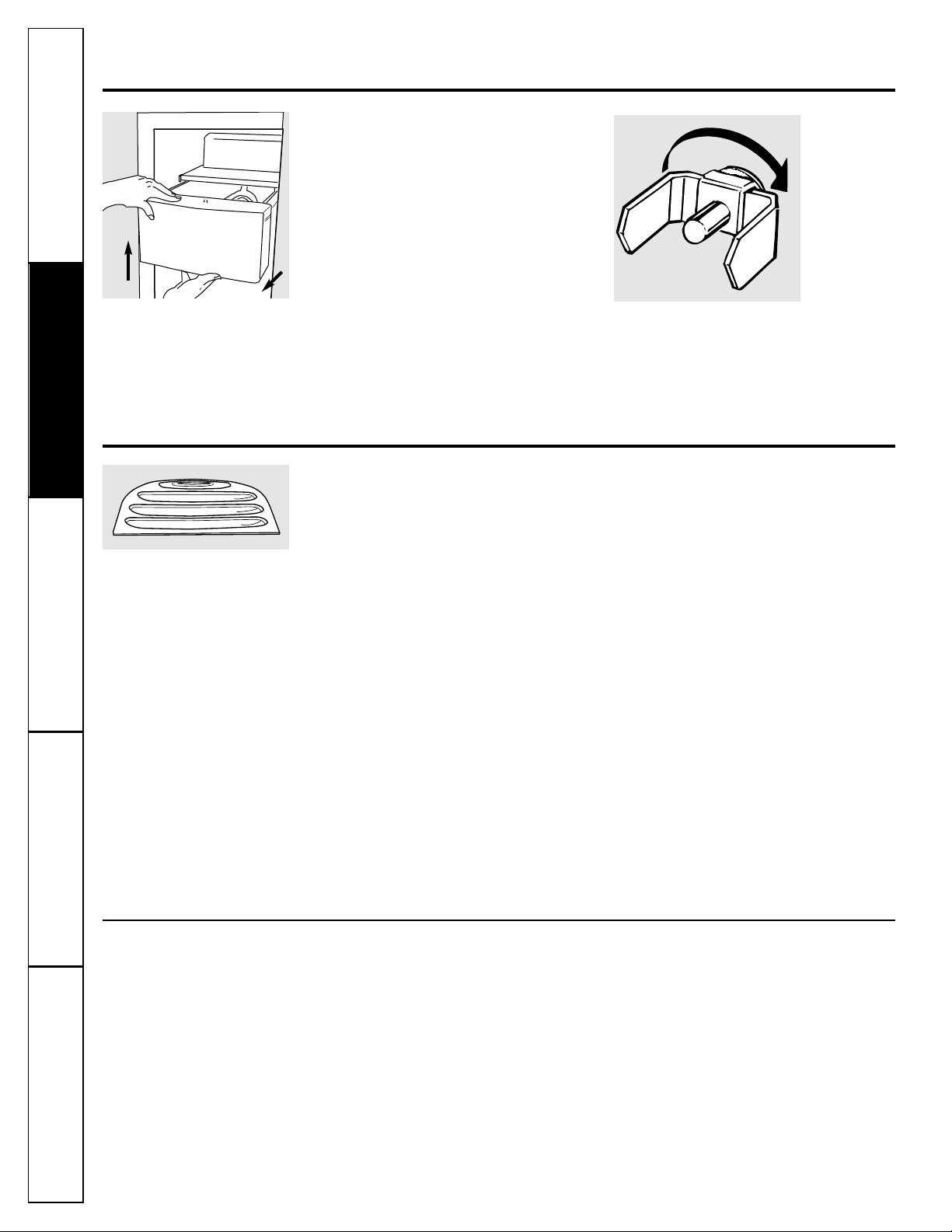
Ice Storage Drawer
on Dispenser Models
To remove:
Set the icemaker power switch to the
O (off)
position. Pull the drawer straight out and
then lift past the
stop
position.
To replace:
When replacing the drawer, be sure to
press it firmly into place. If it does not go
all the way back, remove it and rotate the
drive mechanism 1/4 turn. Then push
the drawer back again.
Rotate
Drive
Mechanism
Dispenser drip area.
About the ice and water dispenser.

17
For long vacations or absences, remove
food and unplug the refrigerator. Clean the
interior with a baking soda solution of one
tablespoon (15 ml) of baking soda to one
quart (1 liter) of water. Leave the doors
open.
Set the icemaker power switch to the
O (off)
position and shut off the water supply to
the refrigerator.
If the temperature can drop below freezing,
have a qualified servicer drain the water
supply system to prevent serious property
damage due to flooding.
GEAppliances.com
Behind the Refrigerator
Be careful when moving the refrigerator
away from the wall. All types of floor
coverings can be damaged, particularly
cushioned coverings and those with
embossed surfaces.
Pull the refrigerator straight out and return
it to position by pushing it straight in.
Moving the refrigerator in a side direction
may result in damage to the floor covering
or refrigerator.
When pushing the refrigerator back, make sure
you don’t roll over the power cord or icemaker
supply line.
Preparing for Vacation
Preparing to Move
Secure all loose items such as shelves and
drawers by taping them securely in place
to prevent damage.
When using a hand truck to move the
refrigerator, do not rest the front or back
of the refrigerator against the hand truck.
This could damage the refrigerator. Handle
only from the sides of the refrigerator.
Be sure the refrigerator stays in an upright
position during moving.
Consumer SupportTroubleshooting Tips
Operating Instructions
Safety Instructions Installation Instructions

Consumer Support Troubleshooting Tips
Operating Instructions
Safety InstructionsInstallation Instructions
18
Replacing the light bulbs.
Setting the controls to OFF does not remove power to the light circuit.
Refrigerator Compartment—Upper Light
Unplug the refrigerator.
The bulbs are located at the top of the
compartment, inside the light shield.
On some models, a screw at the front of
the light shield will have to be removed.
To remove the light shield, press in on
the tabs on the sides of the shield and
slide forward and out.
After replacing the bulb with an
appliance bulb of the same or lower
wattage, replace the light shield and
screws (on some models). When
replacing the light shield, make sure
that the tabs at the back of the shield
fit into the slots at the back of the light
shield housing.
Plug the refrigerator back in.
Refrigerator Compartment—Lower Light
This light is located above the top drawer.
Unplug the refrigerator.
Remove the convertible meat drawer
control knob by pulling straight out.
Lift the light shield up and pull it out.
After replacing the bulb with an
appliance bulb of the same or lower
wattage, replace the shield and
the knob.
Plug the refrigerator back in.
Freezer Compartment
Unplug the refrigerator.
Remove the shelf just above the light
shield. (The shelf will be easier to
remove if it is emptied first.) On some
models, a screw at the top of the light
shield will need to be removed.
To remove the light shield, press in
on the sides, and lift up and out.
Replace the bulb with an appliance
bulb of the same or lower wattage,
and reinstall the light shield. When
reinstalling the light shield, make
sure the top tabs snap securely
into place. Replace the screw
(on some models).
Reinstall the shelf and plug the
refrigerator back in.
Dispenser
Unplug the refrigerator.
The bulb is located on the dispenser
under the control panel.
Remove the light bulb by turning
it counterclockwise.
Replace the bulb with a bulb of the
same size and wattage.
Plug the refrigerator back in.
Tabs
C
O
L
D
D
L
E
O
S
C
T

19
Trim kits and decorator panels.
Read these instructions completely and carefully.
Before You Begin
Some models are equipped with trim kits that allow you to install door panels. You can order
pre-cut black, white, bisque or stainless steel decorator panels from GE Parts and Accessories,
800.626.2002, or you can add wood panels to match your kitchen cabinets.
Panels less than 1/4″(6 mm) thick
When installing wood panels less than 1/4″ (6 mm) thick, you need to create a filler panel, such as 1/8″
cardboard, that will fit between the face of the door and the wood panel. If you are installing the pre-cut
decorator panels, pre-cut filler panels are included in the kit. The combined thickness of the decorator
or wood panel and the filler panel should be 1/4″ (6 mm).
For CustomStyle™models
3/4″ (19 mm) or Raised Panel
A raised panel design screwed or glued to a 1/4″ (6 mm) thick backing, or a 3/4″ (19 mm) routed board
can be used. The raised portion of the panel must be fabricated to permit clearances of at least 2″ (5.1 cm)
from the handle side for fingertip clearance.
Panels thicker than 1/4″ (6 mm), up to 3/4″ (19 mm) max, will require that the outer 5/16″ (8 mm) of
panel perimeter be no thicker than 1/4″ (6 mm).
Weight limitations for custom panels:
Fresh Food 38 lbs. (17 kg) max.
Freezer Door 28 lbs. (13 kg) max.
2″(5.1 cm)
Clearance
Handle Side
Appearance
Panel
Refrigerator
Door
1/4″(6 mm)
Thick Backing
3/4″
(19 mm)
Panels 1/4″thick or less
Panels thicker than 1/4″(6 mm)
1/4″max
1/4″(6 mm) max
3/4″(19 mm)
5/16″ (8 mm)
Consumer SupportTroubleshooting Tips
Operating InstructionsSafety Instructions
Installation Instructions
Consumer Support Troubleshooting Tips
Operating Instructions
Safety InstructionsInstallation Instructions
20
Trim kits and decorator panels.
Freezer Panel
Without Dispenser
Freezer Panel
With Dispenser
Fresh Food Panel
Cut
out
5/16″
(8 mm)
14
15
⁄32″
(36.8 cm)
67
9
⁄32″
(170.9 cm)
1/8″
(3 mm)
FRONT
5/16″
(8 mm)
17
7
⁄8″
(45.4 cm)
14
15
⁄32″
(36.8 cm)
33
5
⁄8″
(85.4 cm)
1/8″
(3 mm)
Cut
out
FRONT
5/16″
(8 mm)
67
9
⁄32″
(170.9 cm)
1/8″
(3 mm)
Cut
out
19
15
⁄32″
(49.5 cm)
FRONT
Dimensions for Custom Wood Panels
The areas at the top of the panels need to be cut out of the panels.

21
Inserting the door panels.
Attach the Top Trim on the Freezer and Fresh Food Doors.
The Top Trim can be found inside the refrigerator
compartment.
With a T-20 Torxdriver, attach the Top Trim, using
two screws on each Top Trim piece, to the top of
each door. Hand tighten only. Make sure that the
top of each panel fits snugly behind the lip of the
Top Trim.
Insert the Freezer Panel and Fresh Food Panel.
Carefully push the freezer panel in until it slides
into the slot behind the door handle. Push the filler
panel (required with some door panels) in behind
the decorator panel. Repeat for fresh food panel.
If your model has a dispenser, this step only applies
to the fresh food panel and top freezer panel.
Insert the Bottom Freezer Panel (on dispenser models).
Carefully push the panel in until it slides into the
slot behind the door handle. Push the filler panel
(required with some door panels) in behind the
decorator panel.
Cut-Out
Cut-Out
Top Trim Screws
Top
Freezer
Panel
Bottom
Freezer
Panel
Side Trim
Side Trim
Fresh
Food
Panel
Read these instructions completely and carefully.
Consumer SupportTroubleshooting Tips
Operating Instructions
Safety Instructions Installation Instructions
Top Trim Screws
22
Install the Side Trim.
These pieces are tucked inside the refrigerator
door handle.
Do not remove the protective film on the outside of
the Side Trim until the Side Trim is installed.
Fit the bottom of the Side Trim under the
Bottom Trim as illustrated.
Hold the Side Trim against the front face of the
decorator panels and fit the Side Trim under
the Top Trim. Make sure the magnetically attached
Side Trim is fitted correctly and that you are
satisfied with the appearance of all the parts.
Side
Trim
Side
Trim
Bottom Trim
Top Trim
Inserting the door panels.
Consumer Support Troubleshooting Tips
Operating Instructions
Safety InstructionsInstallation Instructions
23
Consumer SupportTroubleshooting Tips
Operating InstructionsSafety Instructions
Installation Instructions
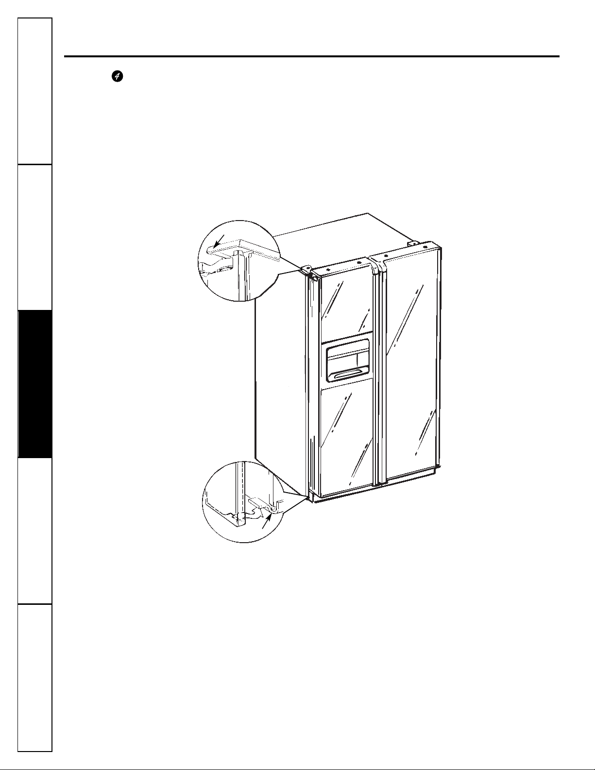
Removing and replacing the doors.
When installing or moving the refrigerator, the doors may need to be removed in order to fit the refrigerator
through a doorway.
Removing the Doors
Make sure the doors are closed and the refrigerator
is unplugged.
Disconnect water line and wiring harness.
Near the lower hinge on the freezer side, push in on
the collars at each end of the coupling, and pull the water
line tubing from the coupling. Also, disconnect wiring
harness. Pull the water line and the harness through the
lower rail.
Remove the hinge covers and the hinges.
In order to access the hinges, the hinge covers need to
be removed. Remove the cover by grasping it on the sides,
near the back of the cover. Push back on the cover and
lift up at the back, then the front.
NOTE: DO NOT use a screwdriver to remove the cover. BE CAREFUL
not to break the rear retaining tab on the hinge cover. Remove the
hinges using a Torx T-20.
Remove the doors.
Carefully rotate the door to 90°. Guiding the disconnected
water line and wiring harness, lift the door straight up.
NOTE: Not lifting the door straight up may damage the bottom hinge.
Place doors on a protected surface.
NOTE: Be careful not to pinch the water tubing and the wire harness
at the bottom of the door.
NOTE: Do not allow the connector to contact the floor. Hard contact
can damage the connector. See “Replacing the Doors.”
Replacing the Doors
Place doors on bottom hinges.
With the door at 90°, lower the door straight down onto
the bottom hinge. Carefully close the door.
NOTE: Not lowering the door straight down onto the bottom hinge
may damage the hinge.
NOTE: Do not allow the connector to contact the floor. Hard contact
can damage the connector.
Replace top hinges and hinge covers.
Reinstall the top hinges using a Torx T-20. Replace the
hinge covers. If the doors are not level, adjust the bottom
right hinge with a 7/16″ open ended wrench.
Reconnect water line and wiring harness.
Insert water tubing back into coupling, making sure the
tubing is pushed far enough into the coupling so that you
no longer see the mark on the tubing. Reconnect the
wiring harness.
Turn on the water supply and plug the refrigerator back in.
90
Hinge Cover
Door
Hinge Pin
Wire Harness
Collars
Connector
BEFORE YOU BEGIN
Read these instructions completely and carefully.
•
IMPORTANT – Save these
instructions for local inspector’s use.
•
IMPORTANT – Observe all
governing codes and ordinances.
• Note to Installer – Be sure to leave these
instructions with the Consumer.
• Note to Consumer – Keep these instructions
for future reference.
• Skill level – Installation of this appliance requires
basic mechanical skills.
• Completion time – Refrigerator Installation
15 minutes
• Proper installation is the responsibility of the
installer.
• Product failure due to improper installation is not
covered under the Warranty.
• Do not install the refrigerator where the temperature
will go below 60°F (16°C) because it will not run often
enough to maintain proper temperatures.
• Do not install the refrigerator where the temperature
will go above 100°F (37°C) because it will not perform
properly.
• Install it on a floor strong enough to support it fully
loaded.
REFRIGERATOR LOCATION
Questions? Call 800.GE.CARES (800.432.2737)
or Visit our Website at:
GEAppliances.com
In Canada, call 1.800.361.3400
or Visit our Website at:
geappliances.ca
Installation
Refrigerator
Instructions
Models 23, 25, 26, 27 & 29
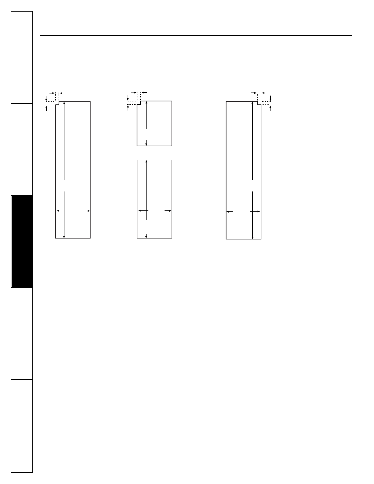
Allow the following clearances for ease of installation,
proper air circulation and plumbing and electrical
connections:
CLEARANCES
The rollers have 3 purposes:
■
Rollers adjust so the door closes easily when opened
about halfway. [Raise the front about 5/8″ (16 mm) from
the floor.]
■
Rollers adjust so the refrigerator is firmly positioned on
the floor and does not wobble.
■
Rollers allow you to move the refrigerator away from the
wall for cleaning.
Final leveling adjustments should be made after the
refrigerator has been installed.
To adjust the rollers on 25′, 26′, 27′and 29′ models:
■
Turn the roller
adjusting screws
clockwise to raise
the refrigerator,
counterclockwise to
lower it. Use a 3/8″
hex socket or wrench,
or an adjustable
wrench.
ROLLERS
If the refrigerator has an icemaker, it will have to be
connected to a cold water line. A GE water supply kit
(containing tubing, shutoff valve, fittings and
instructions) is available at extra cost from your dealer,
by visiting our Website at GEAppliances.com (in
Canada at geappliances.ca) or from Parts and
Accessories, 800.626.2002 (in Canada 1.888.261.3055).
WATER SUPPLY TO THE ICEMAKER
(ON SOME MODELS)
Roller adjusting screw
23′ 25′, 26′, 27′ and 29′
• Sides 1/8″ (4 mm) 1/8″ (4 mm)
• Top 1″ (25 mm) 1″ (25 mm)
• Back 1/2″ (13 mm) 1″ (25 mm)
24
ROLLERS (CONT.)
DIMENSIONS AND SPECIFICATIONS
(for CustomStyle™models)
25
After leveling, make sure that the refrigerator door is 1/16″
higher than the freezer door.
To align the doors, adjust the refrigerator door.
Using a 7/16″ socket wrench, turn the door adjusting
screw to the right to raise the door, to the left to lower
it. (A nylon plug, imbedded in the threads of the pin,
prevents the pin from turning unless a wrench is used.)
After one or two turns of the wrench, open and close
the refrigerator door and check the alignment at the
top of the doors.
To remove the base grille,
open the doors, remove
the screw at each end of
the base grille and then
pull the grille straight out.
7/16″Socket Wrench
Raise
70
1
⁄4″(178.4 cm)
36″
(91.4 cm)
24″ (61 cm)
24″(61 cm)
Cabinet
Water Electrical
3/4″(19 mm) Airspace
(1/2″[13 mm] Gap +
1/4″[6 mm] Wall Plates)
25″(63.5 cm)
Countertop
Installation Instructions
DOOR ALIGNMENT
To adjust the rollers on 23′ models:
Remove the base grille by opening the doors,
removing the screws at each end, and pulling it
straight out.
Turn the front roller
adjusting screws
clockwise to raise
the refrigerator,
counterclockwise to
lower it. Use a 3/8″
hex socket or wrench,
or an adjustable
wrench.
These models also have rear adjustable rollers so you
can align the refrigerator with your kitchen cabinets.
Use a long-handled 5/16″ socket wrench to turn the
screws for the rear rollers–clockwise to raise the
refrigerator, counterclockwise to lower it.
Replace the base grille.
Roller adjusting screws
Refrigerator door
needs to be raised.
INSTALLING THE WATER LINE (ON SOME MODELS)
Recommended copper water supply kits are WX8X2,
WX8X3 or WX8X4, depending on the amount of tubing
you need. Approved plastic water supply lines are GE
SmartConnect™Refrigerator Tubing (WX08X10002,
WX08X10006, WX08X10015 and WX08X10025).
When connecting your refrigerator to a GE Reverse
Osmosis Water System, the only approved installation is
with a GE RVKit. For other reverse osmosis water systems,
follow the manufacturer’s recommendations.
If the water supply to the refrigerator is from a Reverse
Osmosis Water Filtration System AND the refrigerator
also has a water filter, use the refrigerator’s filter bypass
plug. Using the refrigerator’s water filtration cartridge
in conjunction with the RO filter can result in hollow
ice cubes and slower water flow from the water
dispenser.
This water line installation is not warranted by the
refrigerator or icemaker manufacturer. Follow these
instructions carefully to minimize the risk of expensive
water damage.
Water hammer (water banging in the pipes) in house
plumbing can cause damage to refrigerator parts and
lead to water leakage or flooding. Call a qualified
plumber to correct water hammer before installing the
water supply line to the refrigerator.
To prevent burns and product damage, do not hook
up the water line to the hot water line.
If you use your refrigerator before connecting the
water line, make sure the icemaker power switch is in
the
O (off)
position.
Do not install the icemaker tubing in areas where
temperatures fall below freezing.
When using any electrical device (such as a power
drill) during installation, be sure the device is double
insulated or grounded in a manner to prevent the
hazard of electric shock, or is battery powered.
All installations must be in accordance with local
plumbing code requirements.
BEFORE YOU BEGIN
Installation Instructions
WHAT YOU WILL NEED
• Copper or GE SmartConnect
™
Refrigerator Tubing
kit, 1/4″ outer diameter to connect the refrigerator
to the water supply. If using copper, be sure both
ends of the tubing are cut square.
To determine how much tubing you need: measure
the distance from the water valve on the back of the
refrigerator to the water supply pipe. Then add 8′
(2.4 m). Be sure there is sufficient extra tubing (about
8′ [2.4 m] coiled into 3 turns of about 10″ [25 cm]
diameter) to allow the refrigerator to move out from
the wall after installation.
GE SmartConnect™Refrigerator Tubing Kits are
available in the following lengths:
2′ (.6 m) – WX08X10002
6′ (1.8 m) – WX08X10006
15′ (4.6 m) – WX08X10015
25′ (7.6 m) – WX08X10025
Be sure that the kit you select allows at least 8′ (2.4 m)
as described above.
26
NOTE: The only GE approved plastic tubing is that
supplied in GE SmartConnect™Refrigerator Tubing
kits. Do not use any other plastic water supply line
because the line is under pressure at all times. Certain
types of plastic will crack or rupture with age and
cause water damage to your home.
• A GE water supply kit (containing tubing, shutoff
valve and fittings listed below) is available at extra
cost from your dealer or from Parts and Accessories,
800.626.2002 (in Canada 1.888.261.3055).
• A cold water supply. The water pressure must be
between 20 and 120 p.s.i. (1.4–8.1 bar).
• Power drill.
• 1/2″ or adjustable wrench.
• Straight and Phillips blade screwdriver.
• Two 1/4″ outer diameter compression nuts and
2 ferrules (sleeves)–to connect the copper tubing
to the shutoff valve and the refrigerator water
valve.
OR
• If you are using a GE SmartConnect™ Refrigerator
Tubing kit, the necessary fittings are preassembled to
the tubing.
• If your existing copper water line has a flared fitting
at the end, you will need an adapter (available at
plumbing supply stores) to connect the water line to
the refrigerator OR you can cut off the flared fitting
with a tube cutter and then use a compression fitting.
Do not cut formed end from GE SmartConnect
™
Refrigerator tubing.
• Shutoff valve to connect to the cold water line.
The shutoff valve should have a water inlet with a
minimum inside diameter of 5/32″ at the point of
connection to the COLD WATER LINE. Saddle-type
shutoff valves are included in many water supply kits.
Before purchasing, make sure a saddle-type valve
complies with your local plumbing codes.
WHAT YOU WILL NEED (CONT.)
Installation Instructions
27
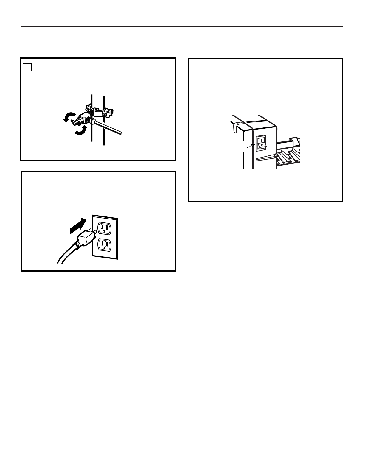
SHUT OFF THE MAIN WATER
SUPPLY
Turn on the nearest faucet long enough to clear
the line of water.
Install the shutoff valve on the nearest frequently used
drinking water line.
1
Choose a location for the valve that is easily
accessible. It is best to connect into the side of a
vertical water pipe. When it is necessary to connect
into a horizontal water pipe, make the connection
to the top or side, rather than at the bottom,
to avoid drawing off any sediment from the
water pipe.
CHOOSE THE VALVE LOCATION
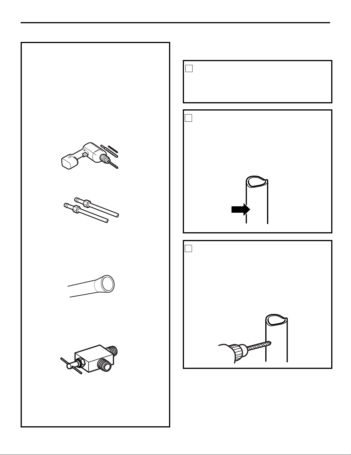
2
DRILL THE HOLE FOR THE VALVE
3
Drill a 1/4″ hole in the water pipe (even if using a
self-piercing valve), using a sharp bit. Remove any
burrs resulting from drilling the hole in the pipe.
Take care not to allow water to drain into the drill.
Failure to drill a 1/4″ hole may result in reduced
ice production or smaller cubes.
Place the compression nut and ferrule (sleeve)
for copper tubing onto the end of the tubing and
connect it to the shutoff valve.
Make sure the tubing is fully inserted into the valve.
Tighten the compression nut securely.
For plastic tubing from a GE SmartConnect
™
Refrigerator Tubing kit, insert the molded end
of the tubing into the shutoff valve and tighten
compression nut until it is hand tight, then tighten
one additional turn with a wrench. Overtightening
may cause leaks.
NOTE: Commonwealth of Massachusetts Plumbing
Codes 248CMR shall be adhered to. Saddle valves
are illegal and use is not permitted in Massachusetts.
Consult with your licensed plumber.
CONNECT THE TUBING TO THE
VALVE
7
Saddle-Type Shutoff Valve
Compression Nut
Packing Nut
Outlet Valve
Ferrule (sleeve)
Turn the main water supply on and flush out the
tubing until the water is clear.
Shut the water off at the water valve after about
one quart (1 liter) of water has been flushed
through the tubing.
FLUSH OUT THE TUBING
8
INSTALLING THE WATER LINE (CONT.)
Installation Instructions
SmartConnect™
Tubing
28
Fasten the shutoff valve to the cold water pipe with
the pipe clamp.
NOTE: Commonwealth of Massachusetts Plumbing
Codes 248CMR shall be adhered to. Saddle valves
are illegal and use is not permitted in Massachusetts.
Consult with your licensed plumber.
FASTEN THE SHUTOFF VALVE
4
Tighten the clamp screws until the sealing washer
begins to swell.
NOTE: Do not overtighten or you may crush the
tubing.
TIGHTEN THE PIPE CLAMP
5
Pipe Clamp
Vertical Cold Water Pipe
Saddle-Type
Shutoff Valve
Washer
Inlet End
Pipe Clamp
Clamp
Screw
Route the tubing between the cold water line and
the refrigerator.
Route the tubing through a hole drilled in the wall
or floor (behind the refrigerator or adjacent base
cabinet) as close to the wall as possible.
NOTE: Be sure there is sufficient extra tubing
(about 8′[2.4 m] coiled into 3 turns of about
10″ [25 cm] diameter) to allow the refrigerator
to move out from the wall after installation
.
ROUTE THE TUBING
6
Installation Instructions
29
Place the compression nut and ferrule (sleeve)
onto the end of the tubing as shown. On the GE
SmartConnect™Refrigerator Tubing kit, the nuts
are already assembled to the tubing.
NOTES:
• Before making the connection to the refrigerator,
be sure the refrigerator power cord is not plugged
into the wall outlet.
• If your refrigerator does not have a water filter,
we recommend installing one if your water
supply has sand or particles that could clog the
screen of the refrigerator’s water valve. Install it in
the water line near the refrigerator. If using GE
SmartConnect™Refrigerator Tubing kit, you will
need an additional tube (WX08X10002) to
connect the filter. Do not cut plastic tube to
install filter.
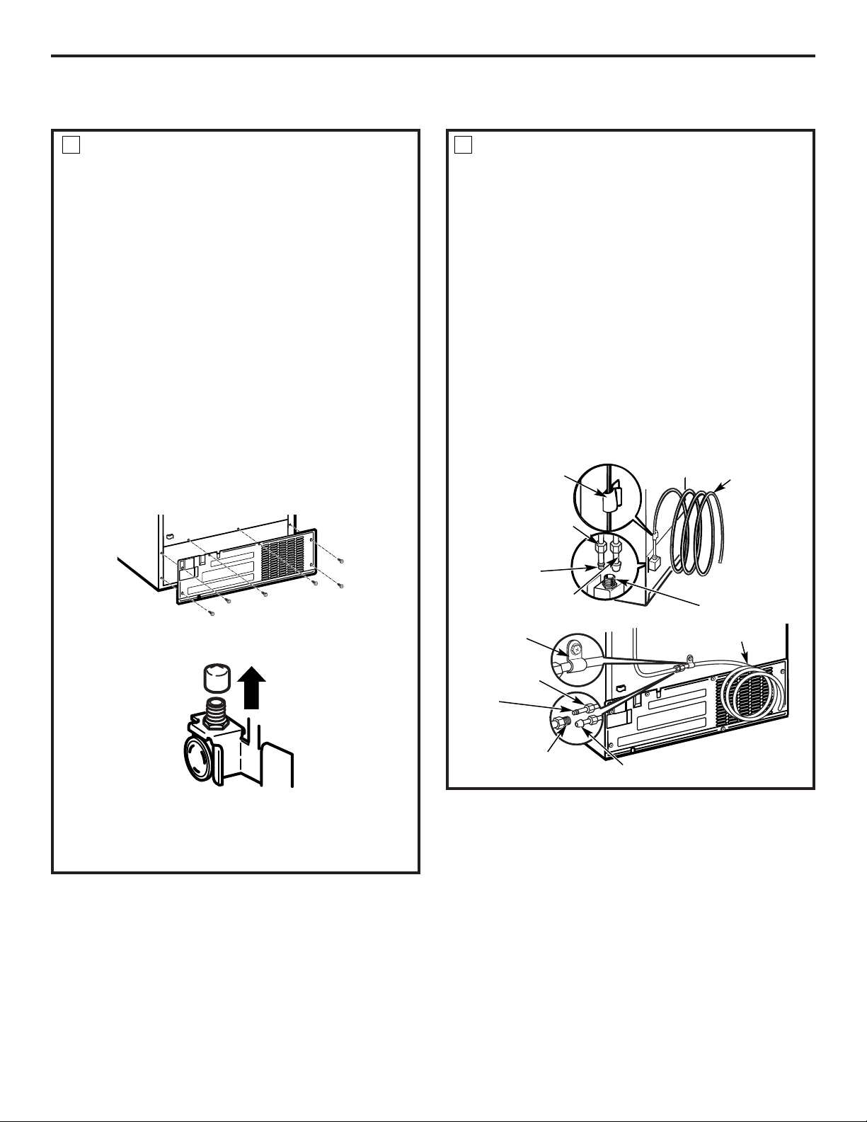
Some models have the refrigerator connection at
the end of tubing located outside the compressor
compartment access cover. On other models, the
compressor compartment access cover must be
removed in order to access the refrigerator
connection at the water valve.
CONNECT THE TUBING TO THE
REFRIGERATOR
9
On models using the refrigeration connection at
the water valve, remove the plastic flexible cap.
Insert the end of the tubing into the water valve
connection as far as possible. While holding the
tubing, tighten the fitting.
For plastic tubing from a GE SmartConnect
™
Refrigerator Tubing kit, insert the molded end
of the tubing into the refrigerator connection and
tighten the compression nut until it is hand tight,
then tighten one additional turn with a wrench.
Overtightening may cause leaks.
Fasten the tubing into the clamp provided to hold
it in a vertical position. You may need to pry open
the clamp.
One of the illustrations below will look like the
connection on your refrigerator.
1/4″
Compression
Nut
Tubing
Clamp
1/4″
Tubing
Ferrule
(sleeve)
Refrigerator
Connection
SmartConnect
™
Tubing
1/4″Tubing
Tubing Clamp
1/4″
Compression Nut
Ferrule
(sleeve)
SmartConnect™Tubing
Refrigerator Connection
CONNECT THE TUBING TO THE
REFRIGERATOR (CONT.)
9
30
Installation Instructions
Set the icemaker power switch to the
l (on)
position.
The icemaker will not begin to operate until it
reaches its operating temperature of 15°F (–9°C)
or below. It will then begin operation automatically
if the icemaker power switch is in the
l (on)
position.
NOTE: In lower water pressure conditions, the
water valve may turn on up to 3 times to deliver
enough water to the icemaker.
Power
switch
START THE ICEMAKER
Arrange the coil of tubing so that it does not vibrate
against the back of the refrigerator or against the
wall. Push the refrigerator back to the wall.
PLUG IN THE REFRIGERATOR
11
Tighten any connections that leak.
TURN THE WATER ON AT THE
SHUTOFF VALVE
10
Replace access cover.
INSTALLING THE WATER LINE (CONT.)
 Loading...