

GE PSI23MCMAWW, PSI23MCMABB, PSI23MCLAWW, PSI23MCLACC, PSI23MCLABB Owner’s Manual
GEApp/iances.com
Safety Instructions ........... 2-4
Operating Instructions
Additional Features ............. 9
Automatic Icemaker ........... 11
Care and Cleaning .......... 13, 14
Ice and _4'ater Dispenser ........ 12
Refiigerator Doors ............. 9
Replacing the Light Bulbs ....... 15
Shelves and Bins ............. 7, 8
Crispers and Pans ............. 10
TemperaUlre Controls ........... 5
VCater and FreshSaver TM Fihers .... 6
Installation Instructions
Preparing to Install
the Refligeramr . ........... 22, 23
Removing and Replacing Doors . .21
Trim Kits and Panels ........ 16-20
h'ater Line Installation ...... 24-28
Troubleshooting Tips ....... 30-32
Normal Operating Sounds ...... 29
Consumer Support
Consumer Support ..... Back Cover
Performance Data Sheet ........ 36
Product Registration ........ 33, 34
State of California _'ater
Treatment Device Certificam ..... 37
¼'arranty (Canadian) ........... 38
h'arranty (U.S.) ............... 39
Models21,23,25,27,and29
Profile C6te fi C6te
Rdfrigdrateurs
La sectionfrangaise commencea la page40
Profile Lado a Lado
Refrigeradores
La seccion en espa#ol empiezaen la pagina 74
Write the model and serial numbers here:
#
#
Find these nmnbers on a label inside
the refl'igerator compartment at the
top on the right side.
200D2600PO09 49-60157 07-01JR
IMPORTANTSAFETYINFORMATION.
READALLINSTRUCTIONSBEFOREUSING.
A WARNING!
Use this appliance only for its intended purpose as described in this Owner's Manual
SAFETYPRECAUTIONS
When using electrical appliances, basic safety precautions should be followed, including the following:
_,':;This refl-igerator must be properly installed
and located in accordance with tl/e Installation
h_structions beiore it is used.
_,':;Do not allow children to climb, st;rod or hang
on the shelves in tile refl'igerato_: They could
damage tile refligerator and seriously iqitu'e
themselves.
:)::Do not touch the cold surli_ces in the fl'eezer
compartment when hands are damp or wet.
Skin may stick to these extremely cold surii_ces.
i,;:Do not store or use gasoline or other flammable
\:q_o_s and liquids in tile vicinity oI this or any
other appliance.
i,_:;In refiigerato_s with atltOll/atic icemake_s,
avoid comact with the moving parts of the
ejector mechanism, or with the heaOng
element located on tl/e bottom of tile icemake_:
Do not place finge_s or hands on tile automatic
icemaking mechanism while the reti_igerator
is plugged in.
i,_:;Keep finge_s out _ff tl/e "pinch point" areas;
clearances between the doo_ and between
the (loo_s and cabinet are necessmilv small.
Be careful closing (loo_s when children are
in the area.
i/:;Unplug tile refrigerator betore cleaning and
making repairs.
NOTE."We stronglyrecommendthatany servicingbe
performedby a quafified individual.
i/:;Setting either or both controls to 0 (0If)does not
remove power to the light circuit.
::NDo not refl'eeze fl'ozen foods which have
thawed complemly.
vvvvw.GEAppliances.com
DANGER!RISKOFCHILDENTRAPMENT
PROPERDISPOSALOFTHEREFRIGERATOR
Child entrai)ment and suffocation are not i)rol)lems
of the past. Junked or abandoned refl_igeratm_ are
still dangerous...even if they will sit fin" "just a few
days." If you are getting rid of yore" old reflJgeratoi;
please ti_llow the instructions below to help prevent
accidents.
Before YouThrowAway YourOldRefrigerator
or Freezer:
i_i;:Take off the dome.
i_ I,eaxe the shelves in place so that children ma)
not easilx climb inside.
CFCDisposal
Ymr old refi_igerator may have a cooling system
that used CFCs (chlorofluorocarbons). CFCs are
believed to ham_ stratospheric ozone.
If you are throwing away yore" old reflJgeratoi; make
sure the CFC refl_igerant is removed fin" proper
disposal by a qualified se_'ice_: If you intentionally
release this CFC reflJgerant you can be subject to
fines and impfisomnent under provisions of
enviromn enml legislation.
USEOFEXTENSIONCORDS
Because ofpotential safety hazards under certain conditions, we strongly recommend against the use
of an extension cord.
However, ifxou must use an extension cord, it is absolutelx necessary that it be a UITlisted (in the United
States) or a (;SA-listed (in (_anada), 3-wire grom_ding type appliance extension cord haxing a grom_ding
type I)lu°_ and outlet and that the electrical rating, of the cord be 15 amperes (minimum) and 120 xolts.
3
IMPORTANTSAFETYINFORMATION.
READALLINSTRUCTIONSBEFOREUSING.
a, WARNING!
HOWTOCONNECTELECTRICITY
Do not, under any circumstances, cut or remove the third (ground) prong from the power cord.
For personal safety this appliance must beproperly grounded.
The power cord of this appliance is equipped with
a 3-prong (grounding) plug which inates with
a standard 3-prong (gromMing) wall outlet to
minimize the possibili F of electric shock hazard
fl'om this appliance.
Have the wall outlet and circuit checked by
a qualified electrician to make sure the outlet
is prol)erly grotmded.
If the outlet is a standard 2-prong outlet, it is
yore" personal responsibility and obligation to
have it replaced with a i)roperly grotmded
3-prong wall outlet.
The reli_igerator should always be plugged into
its own individual electrical outlet which has
a voltage rating that matches the rating plate.
This provides the best perfin_nance and also
I)rexents oxerloading, house wiring circuits which
could cause a fire hazard fl'om oxerheated wires.
Never tmi)lug )'ore" refl]gerator bv pulling on the
power cord. Mways grip plug firefly aim pull
straight out fl'om the outlet.
Repair or replace ilmnediately all power coMs that
have becolne fl'ayed or otherwise dalnaged. Do not
use a cord that shows cracks or abrasion damage
along its length or at either end.
\A]_en moving the refl{gemtor away fl'om the
wall, be careflll not to roll over or damage the
power cord.
USEOFADAPTERPLUGS(Adapterp/ugsnotpermittedincanada)
Because of potential safety hazards under certain conditions, we strongly recommend against
the use of an adapter plug.
Howevet; if' you, must use an adapter; where local
codes pemfit, a temporary connection may be made
to a l)roperly grotmded 2-prong wall outlet by use
of a UI Aisted adapter a\:lilable at m()st local
hai'dware stores.
The linger slot in the adapter must be aligned Mth
the larger slot in the wall outlet to provide proper
polafi F in the com_ecfion of the power cord.
When disconnecting the power cord fl'om the
a(lapte_; alwa_:s hold the adapter in place with one
hand while pulling the power cord l)lug with the
other hand. If this is not done, the adapter gmtmd
temfinal is very likely to break with repeated use.
If the adapter grotmd temfinal breaks, DO NOT
USEthe refrigerator tmfil a l)roper grotmd has
been established.
Attaching the adapter ground terminal to a waft outlet
cover screw does not ground the appliance un/ess the
cover screw is metal, and not ihsu/ated, and the waft
outlet is grounded through the house wiring. Youshou/d
have the circuit checkedby a qualified e/ectriclan to make
sure the outlet is proper/y grounde_
READANDFOLLOWTHISSAFETYINFORMATIONCAREFULLY.
SAVETHESEINSTRUCTIONS
4
Aboutthe temperaturecontrols, vvvvw.GEAppliances.com
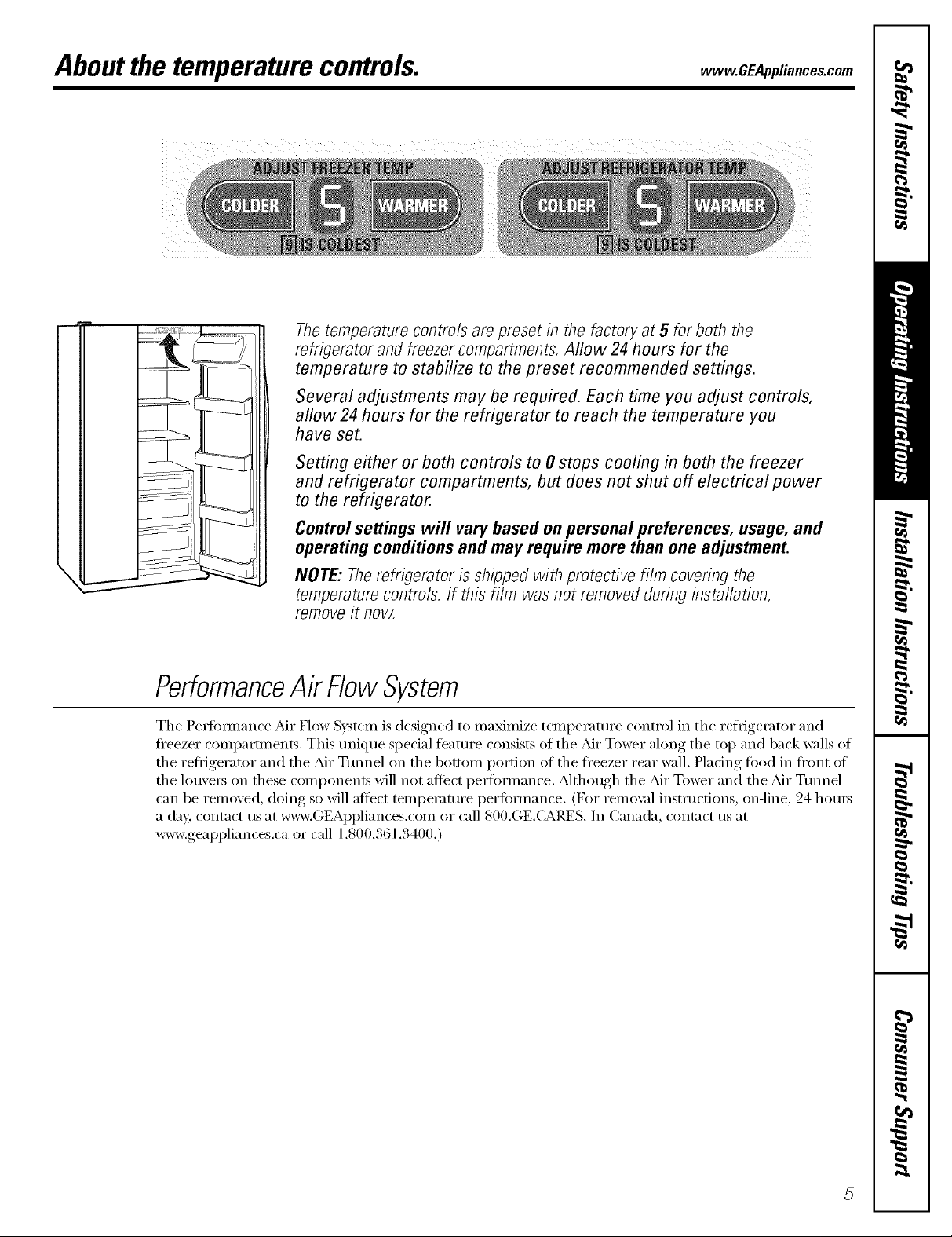
The temperature controls are preset in the factory at 5 for both the
refrigerator and freezer compartments. Allow 24 hours for the
temperature to stabilize to the preset recommended settings.
Several adjustments may be required. Each time you adjust controls,
allow 24 hours for the refrigerator to reach the temperature you
have set.
Setting either or both controls to 0 stops cooling in both the freezer
and refrigerator compartments, but does not shut off electrical power
to the refrigerator.
Controlsettings will vary based on personal preferences, usage, and
operating conditions and may require more than one adjustment.
I
I
NOTE: Therefrigerator is shipped with protective film covering the
temperaturecontre/s./f this film was not removed during installation,
removeit now.
PerformanceAir FlowSystem
The Pet-fi)nnance Air How System is designed to ma_mize temi)erature control in the refrigerator and
fl'eezer comi)artments. This tmique special fbattu'e consists of the Air Tower along the top and back walls of
the refl_igerator and the Air Ttmnel on the bottom portion of the fl'eezer rear wall. Plating ti_od in fl'ont of
the lou\'ets on these components will not affect i)et-fk)nnance. _Mthough the Air Tower and the Air Ttmnel
can be removed, doing so will aftect temperattu'e perfbm/ance. (For remo_:fl instructions, on-line, 24 hotu_
a da); contact us at _vw.GEAl)pliances.com or call 800.GE.(:ARES. In Canada, contact us at
w_v,geappliances,ca or call 1,800,361,3400,)
Aboutthe water andFreshSaverTMfilters.
On some models
'_ the water filter cartridge on the dispenser.
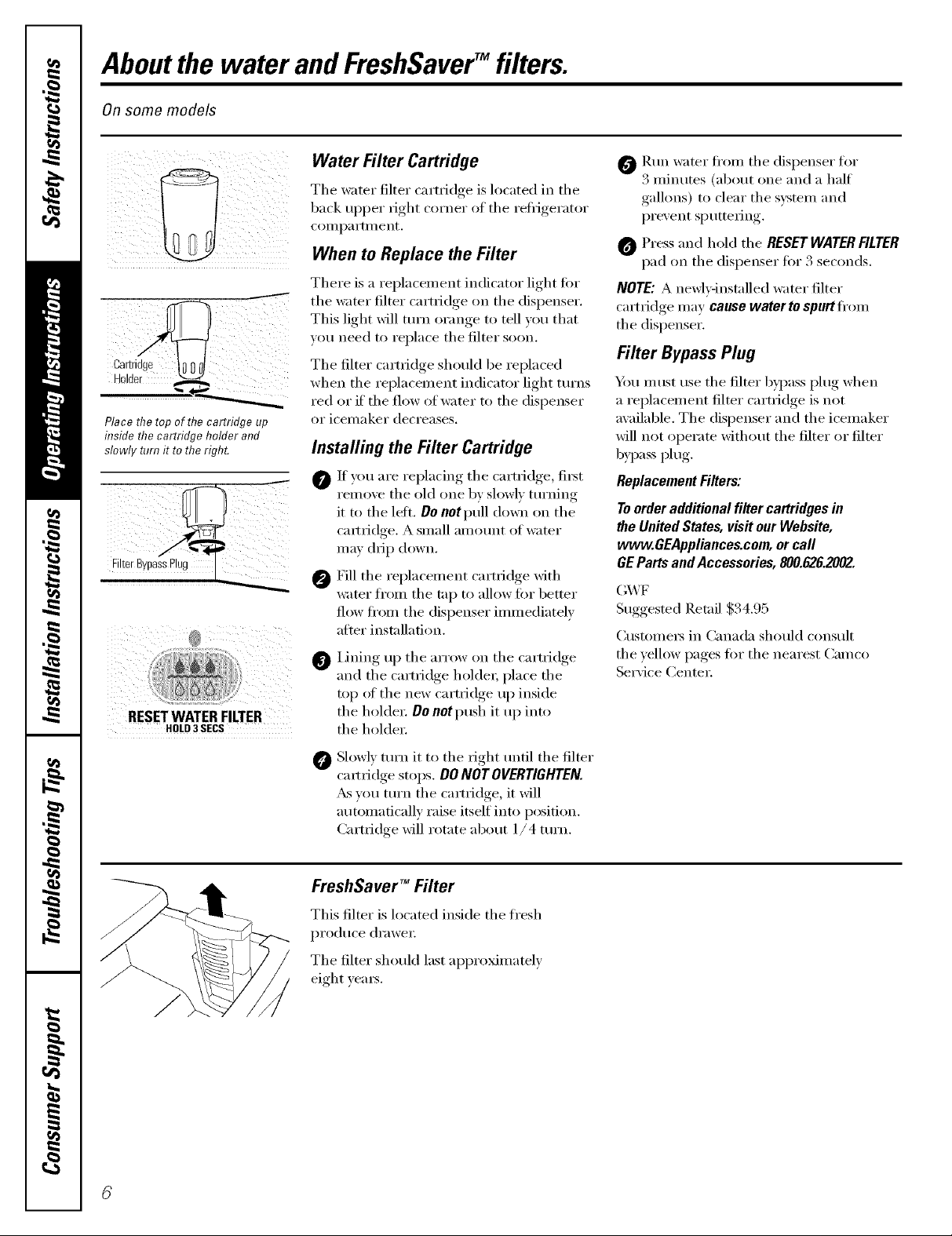
Place the top of fl?ecartridge up
inside the cartridge holder and
slowly turn it to the right.
RESETWATERFILTER
HOLD3SECS
Water Filter Cartridge
The water filter cartridge is located in the
back tipper fight corner of the refl_gerator
conlpartmeilt.
When to Replace the Filter
There is a replacement indicator light for
This light will turn orange to tell you that
you need to replace the filter soon,
The filter cartridge should be replaced
when the replacement indicator light turns
red or if the flow of water to the dispenser
or icemaker decreases,
Installing the Filter Cartridge
0 If you are rei_lacino_ the cartridge, ti_t
remoxe the old one by slowl) turning
it to the letL Do not pull down on the
cmtridge, A small amount of water
may drip down.
Fill the replacement cartridge with
water fl'om the tap to allow fi)r better
flow fl'om the dispenser immediately
alter installation.
Lining up the arrow on the cartridge
@
and the cartridge holder, place the
top of the new cartridge up inside
the holdex; Do not push it up into
the holder:
0 Run water fl'om the dispenser tot
3 minutes (about one and a half
gallons) to dear the system and
prevent sputtering.
Press and hold the RESETWATERFILTER
pad on the dispenser for 3 seconds.
NOTE:A newEqnstalled water filter
cartridge may cause water to spurt fl'om
the dispenser.
Filter Bypass Plug
Y)u must use the filter bypass plug when
a replacement filter cartridge is not
available, The dispenser and the icemaker
will not operate without the filter or filter
bypass plug.
Replacement Filters:
To order additional filter cartridgesin
the United States, visit our Website,
www.GEAppliances.com,or call
GE Parts and Accessories, 800.626.2002.
(;X,_ F
Suggested Retail $34.95
Customer5 in Canada should consult
the _ellow pages fi)r the nearest Cameo
Serx ice Center;
Slowly turn it to the right tmfil the filter
@
cam_idge stops. DO NOT OVERTIGHTEN.
_s you turn the cartridge, it will
automatically raise itself into position.
Cartridge will rotate about 1/4 turn.
FreshSave# _ Filter
This filter is located inside the fl'esh
produce (h'awe_:
The filter should last approximately
eight yems.
Abouttheshelvesandbins. vvww.GEAppliances.com
Not all features are on all models.
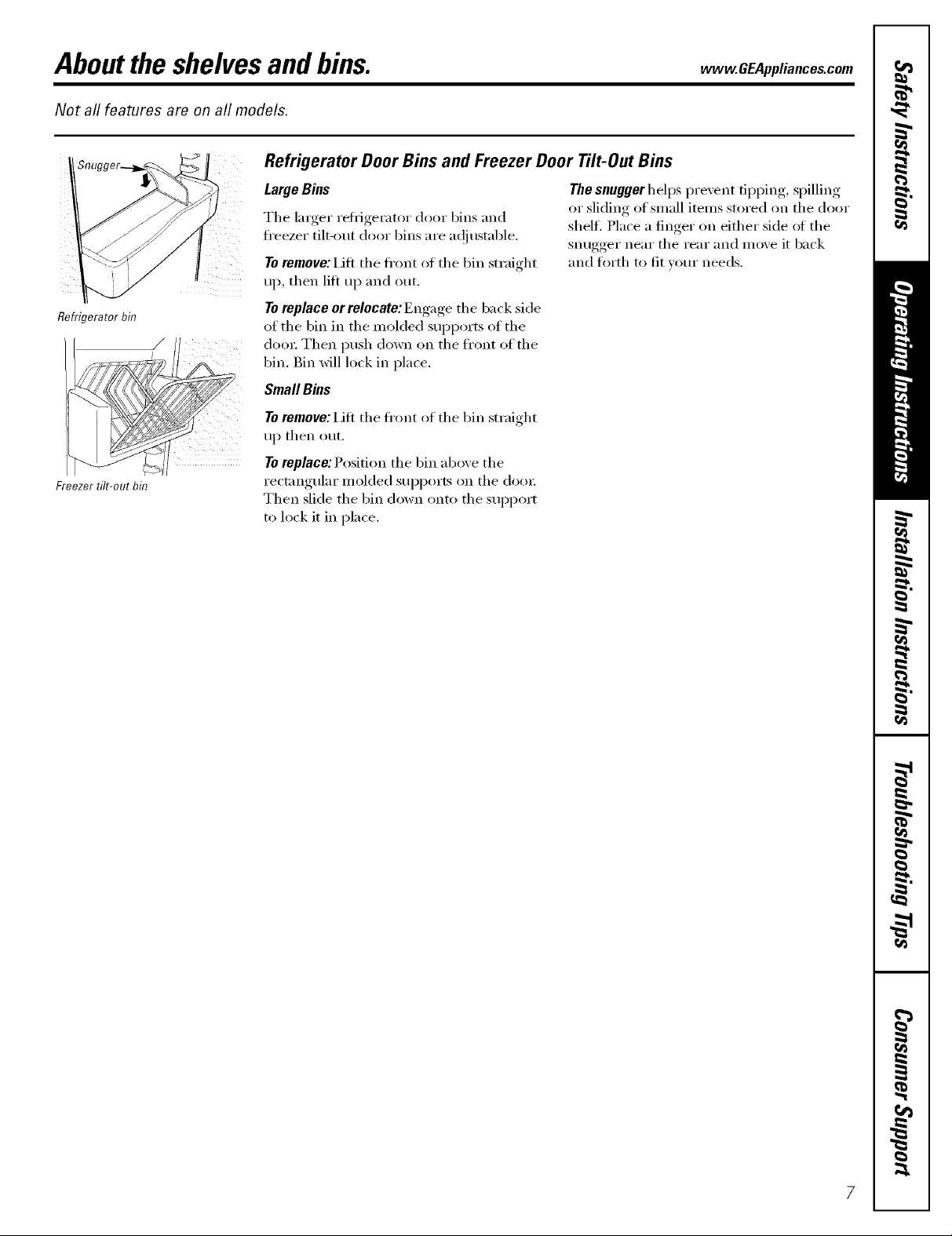
Refrigerator Door Bins and Freezer Door Tilt-Out Bins
Refrigerator bin
Freezer tilt-out bin
LargeBins
The larger reti_igerator door bins and
fl'eezer tilt-out door bins are ac!iustable.
To remove: i]fi the fl'ont of the bin straight
up, then lift up and out.
Toreplaceorrelocate:Engage the back side
of the bin in the molded SUl)ports oI the
doo_; Then push down on the fl'ont of the
bin. gin will lock in place,
SmallBins
Toremove: Lift the fl'ont of the bin straight
up then out.
Toreplace: Position the bin above the
rectangular molded supports on the (loo_;
Then slide the bin down onto the support
to lock it in place,
The snugger helps prevent tipping, spilling
or sliding of small items stored on the door
shel£ Place a finger on either side oI the
snugger near the rear and move it back
and fl)rth to fit your needs.
Abouttheshelvesandbins.
Not all features are on all models.
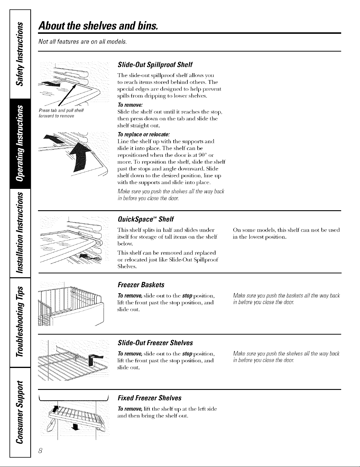
Slide-Out Spillpmof Shelf
The slide-out spillproof shelf allows )ou
to reach items stored behind othe_. The
special edges are designed to hel I) pre',ent
spills fl'om dripping to lower shelxes.
Toremove:
Press tab andpull shelf
forward to remove
Slide the shelf out tmtil it reaches the stop,
then press down on the tab and slide the
shelf straight out.
To replace or relocate:
I,ine the shelf up with the suI)ports and
slide it into place. The shelf can be
repositioned when the door is at 90 ° or
more. To reposition the shelf, slide the shelf
past the stops and angle downward. Slide
shelf down to the desired position, line up
with the sui)ports and slide into place.
Makesureyoupushtheshelvesall the wayback
in beforeyouclosethedoor
i ¸¸i /(j
QuickSpace TM Sheff
This shelf splits in half and slides trader
itself for storage of tall items on the shelf
below.
This shelf can be removed and replaced
or relocated just like Slide-Out Spillpro_ff
Shelves.
Freezer Baskets
Toremove, slide out to the stopposition,
lift the ti'ont past the stop position, and
slide out.
Slide-Out Freezer Shelves
Toremove, slide out to the stopposition,
lift the ti'ont past the stop position, and
slide out.
On some models, this shelf can not be used
in the lowest position.
Makesureyoupushthebasketsall thewayback
in beforeyouclosethedoor
Makesureyoupushtheshelvesall thewayback
in beforeyouclosethedoor
) Fixed Freezer Shelves
Toremove,lift the shelf uI) at the left side
and then bring the shelf out.
Aboutthe additionalfeatures, vvvvw.GEAppliances.com
Not all features are on all models.
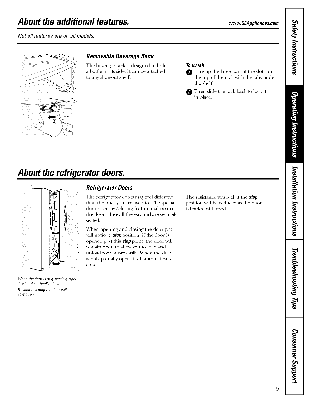
Removable Beverage Rack
The beverage rack is designed to hold
a bottle on its side. It can be attached
to any slide-out shel£
Toinstall'.
Line up the large part oI the slots on
the top of the rack with the robs tamer
the shelf.
Then slide the rack back to lock it
in place,
Aboutthe refrigeratordoors.
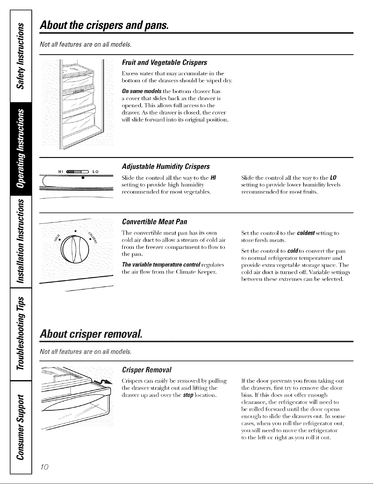
Refrigerator Doors
The reflJgerator doox_ may teel difli_rent
than the ones you are used to. The special
door opening/closing teattli'e illakes Stli'e
the (loo_ close all the way and are secm'elv
sealed.
When opening and closing the door you
will notice a stop position, If the door is
opened past this stop point, the door will
remain open to allow you to load and
tmload fi_od more easily: When the door
is only partially open it will automatically
close.
When the door is only partially open
it will automatically close.
Beyond this stop the door will
stay open.
The resist;race wm teel at the stop
position will be reduced as the door
is loaded with fi_od.
Aboutthe crispersandpans.
Not all features are on all models.
Fru# and Vegetable Crispers
Excess water that may accunmlate in tile
bottom of the (lrawei_ should be wiped dry.
On some models the bottom drawer has
a cover that slides back as the drawer is
opened. This allo_vs fllll access to the
drawei: _&sthe drawer is closed, the cover
will slide torward into its original position.
HI _ LO
0
Adjustable Humidity Crispers
Slide the control all the way to the HI
setting, to l)r°xicle high humidity
reconllnended tor inost xegetnbles.
Convertible Meat Pan
Tile convertible meat pan has its own
cold air duct to allow a stream of cold air
fI'oI/1 tile fl'eezer COI/ll)}lI'tIllent to [lOW to
tile pail
Thevariabletemperaturecontrolregulates
tile air flow ti'om tile Climate KeepeI:
About crisper removal
Slide tile control all tile way to tile LO
,settiw,_ to proxide lower humidit} le_ els
reconllnended fi)r inost fl'uits.
Set tile control to tile coldest setting to
store fresh i/leats.
Set tile control to coldto convert tile pan
to nomml refi_igerator teinperamre and
provide extra vegetable storage space. The
cold air duct is turned off'. Variable settings
between these extremes can be selected,
Not all features are on all models.
Crisper Removal
Crispel_ can easily be removed by pulling
tile drawer straight out and lifting tile
drawer up and _wer tile stop location.
10
If the door prevents you fl'om taldng ()tit
the draweI_, fil_t ti T to remove the door
bins, If this does not offer enough
clem'ance, the reflJgerator will need to
be rolled fl/rward until tile door opens
enough to slide tile (hawe_ out. In some
cases, when you r(/ll tile refl_igerator out,
you will need to re(we tile refl_igeiator
to tile left or right as you roll it out.
Aboutthe automaticicemaker, vvww.GEAppliances.com
A newly-installed refrigerator may take 12to 24 hours to begin making ice.
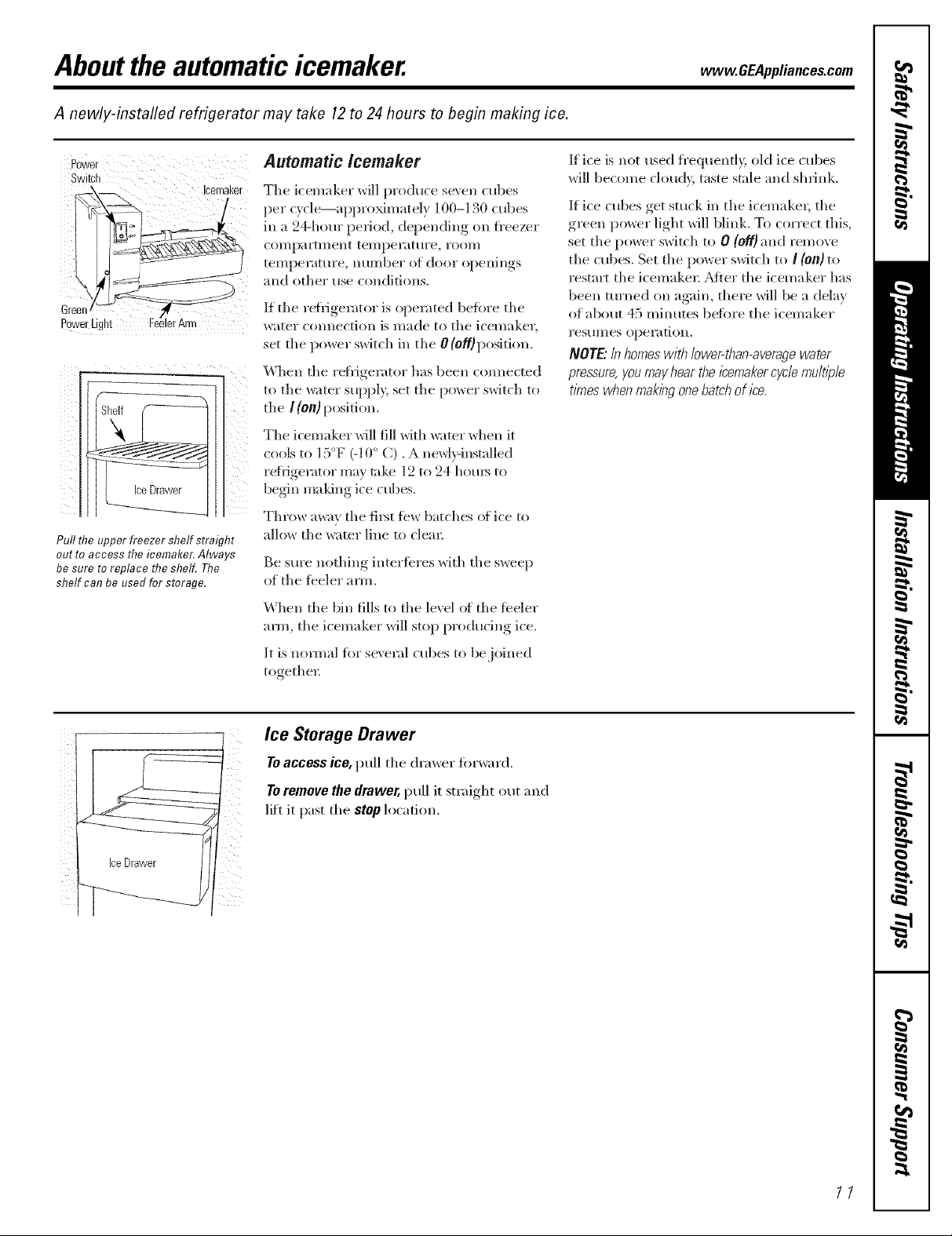
Power Automatic/cemaker If ice is not used fl'equently, old ice cubes
Switch will become cloud}, taste stale and shrh_k.
PowerLght !fArm
Pull the upper freezer shelf straight
out to access the icemaker. Always
besure toreplace the shelf. The
shelf can be used for storage.
Icemaker
The icemaker will produce seven cubes
per cycle---appro_mately 100-130 cubes
in a 24-hem" period, depending on fl'eezer
COlllpalq_l//ent telllpel'attlIe, rOOl/l
temperature, number of door openings
and other use conditions.
If the refligerator is operated betbre the
water c(mnection is made to the icemake_;
set the power switch in the 0 (o_)position.
When the re/iigerator has been c(mnected
to the water supply; set the l)O_,_erswitch to
the / (on) position.
The icemaker will fill with _ater _d_en it
cools to 15°ff (-10° C). A newl}qnstalled
beginref]igerat°rma,tal<emaldngice cubes.12to 24 houls to
Throw away tile filst _bw batches (>iice to
allow the water line to clear
Be sure nothing interibres with the s*_eep
of the tbeler arm,
When the bin fills to the level (>f"the feeler
arm, the icemaker will stop producing ice,
It is nomml ior se\ end cubes to be joined
togethel:
If ice cubes get stuck in the icemakel, tile
green power light will blink. To correct this,
set the power switch to 0 (Of/)and remove
the cubes. Set the power switch to / {On)to
restart the icemaker. _Mter the icemake_ has
been turned on again, the_e will be a delay
of about 45 minutes beik)re the icemaker
resumes operation.
NOTE"/n homeswith lower-than-averagewater
pressure,you mayhear the/?emakercycb mult))b
tbTeswhenmakbgonebatchof ira
//i !i
Ice Storage Drawer
Toaccess ice, pull the drawer forward.
Toremove the drawer, pull it straight out and
lift it past the stop location.
11
Aboutthe ice and water dispenser.
On some models
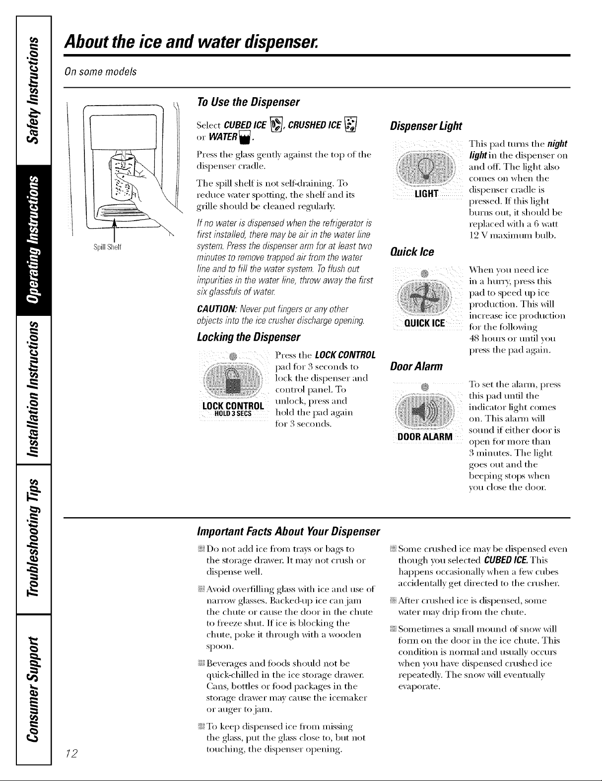
To Use the Dispenser
SpillShelf
Select CUBEDICE _, CRUSHEDICE
or WATER_.
Press the glass gently against the top ot the
dispenser cradle.
The spill shelf is not self-draining. To
reduce water spotting, the shelf and its
grille should be cleaned regularly:
If no water is dispensed when the refn_?eratoris
first insta//ed, there may be air in the water fine
system. Pressthe dispenser arm for at/east two
minutes to remove trapped air from the water
fine and to fl// the water system. Toflush out
impurities in the water fine, throw away the first
six g/assfu/s of water
CAUTION: Never put fingers or any other
objects into the ice crusher discharge opening.
Lockingthe Dispenser
@ Press the LOCKCONTROL
....... pad fi>r 3 seconds t(>
lock the dispenser and
c )ntrol panel To
LOCKCONTROL ,,,llock, l>,'essand
HOLD3SECS hold the pad again
fin" 3 seconds.
Dispenser Light
This pad turns tile night
and off. The light also
comes on when the
dispenser cradle is
pressed. If this light
bm'ns out, it should be
replaced with a 6 watt
12 V maximmn bulb.
OuickIce
\,\]/en you need ice
in a hmTy, press this
pad to speed up ice
production. This will
increase ice production
QUICK ICE for tile fi)llowing
48 horns or tmdl you
press the pad again.
OoorAlarm
@ To set the alamo, press
this pad tmtil the
indicator light comes
on. This alam_ will
DOOR ALARM
so/md if either door is
open Jk)i" illOi'e tl/_lIl
3 minutes. The light
goes ()ut and the
beeping stops when
VO/I close the door
/2
Important Facts About Your Dispenser
_i;Do not add ice fl'om trays or bags to
the storage (h'awe_: It may not crush or
dispense well•
N Avoid ovedilling glass with ice and use of
narrow glasses. Backed-up ice can jam
the chute or cause the door in the chute
to fl'eeze shut. ]f ice is blocking the
chute, poke it through with a wooden
Sl)OOn.
N Beverages and fi)ods should not be
qtfick-chilled in the ice storage (h'awe_:
Cans, bottles or fi)od packages in the
storage drawer may cause the icemaker
or auger to jam.
_i;T() keep dispensed ice ti'()m missing
the glass, put the glass close t(), but not
t()uching, the dispenser opening.
Yi;Some crushed ice may be dispensed even
though you selected CUBED ICE.This
happens occasionally when a tew cubes
accidentally get directed to the crusher.
N_Mter crushed ice is dispensed, some
wamr may drip ti'om the chute.
N Sometimes a small molmd of snow will
fi)m_ on the door in the ice chute. This
condition is nomml and usually occm_
when you have dispensed crushed ice
repeatedly. The snow will eventually
eval)orate.
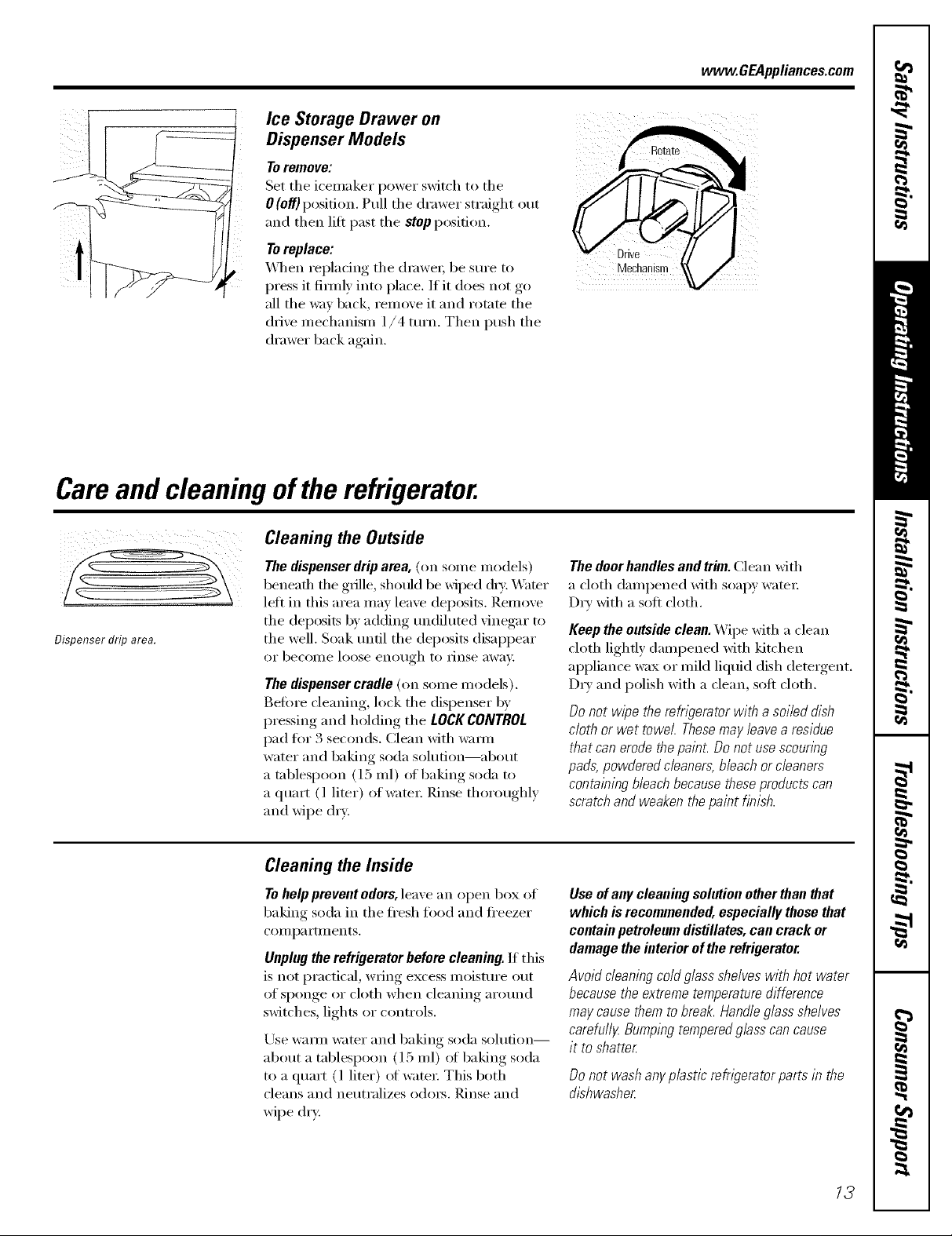
Ice Storage Drawer on
Dispenser Models
To remove:
Set the icemaker power switch to the
0 (off) position. Pull the drawer straight out
and then lilt past the stop position.
Toreplace:
_._]_en replacing the (lmwe_; be sure to
press it firefly into place. If it does not go
all the way back, remove it and rotate the
drive mechanism 1/4 turn. Then push the
drawer back again.
Careand cleaning of the refrigerator.
www.GEAppliances.com
Dispenser drip area.
Cleaning the Outside
The dispenser drip area, (on some models)
beneath the grille, shotfld be wiped (h T. Water
lett in this area may leave deposits. Remove
the deposits by adding tmdiluted vinegar to
the well. Soak tmfil the deposits disappear
or becoIlle loose enotlgh to IJnse awav,
The dispenser cradle (on some models).
Befi)re deaning, lock the dispenser by
pressing and holding the LOCK CONTROL
pad tor 3 seconds. Clean with w;mn
water and baking soda solution--about
a tnblespoon (l 5 ml) ot baking soda to
a quart (l liter) of water: Rinse thoroughly
and wipe drx;
Cleaning the Inside
To help prevent odors, leave an open box of
baking soda in the fl'esh tood and fl'eezer
COil] pa I'tlll ents,
Unplug the refrigerator before cleaning. If this
is not practical, wring excess moisture out
of sponge or cloth when cleaning around
switches, lights or controls.
Use warm water and baking soda solution--
about a tablespoon (15 ml) of baking soda
to a quart (l liter) oI water This both
cleans and neutralizes od(n5. Rinse and
wipe drx;
The door handles and trim. Clean with
a cloth dampened with soalu water;
Dry with a soft cloth.
Keep the outside clean. Wipe with a clean
cloth lightly daml)ened with kitchen
al)pliance wax or mild liquid dish detergent.
D_T and polish with a clean, soft cloth.
Do not wipe the refrigerator with a soiled dish
cloth or wet towel. Thesemay leave a residue
that can erode the painL Do not use scouring
pads,powdered cleaners, bleach or cleaners
containing bleach because these products can
scratch and weaken the paint finish.
Use of any cleaning solution other than that
which is recommended, especially those that
contain petroleum distillates, can crack or
damage the interior of the refrigerator.
Avoid cleaning cold glass shelves with hot water
because the extreme temperature difference
may cause them to break. Handie g/ass shelves
carefull_z Bumping tempered giass can cause
it to shatter
Donot washanyp/asticrefngeratorpartsin the
dishwasher
13
Careand cleaning of therefrigerator.
Behind the Refrigerator
Be careflll when moving the refl_igerator
away flx)m the wall. MI types ot floor
coverings can be dmnaged, particularly
cushioned coverings and those with
elllbossed s/irtilces.
Pull the reti_igerator straight out and retm'n
it to position by pushing it straight in.
Moving the refrigerator in a side direction
may result in damage to the floor covering
or refl_igeratm:
Preparing for Vacation
For long \;ications or absences, rei//ove
fi)od and Ulq)lug the refl_igeratoi: Clean
the interior with a baking soda solution
of one tablespoon (15 inl) of baking soda
to one quart (1 liter) of watei: i,eave the
dooI's open,
Set the icelnaker power switch to the
0 (Off)position aim shut off the water supply
to the reflJgerato_:
When pushing the refrigerator back, make sure
you don't rofl over the power cord or icemaker
supply line {onsome models).
If the temperature can drop below
fl'eezing, have a qualified servicer drain the
water supply system (on some models) to
prevent serious propei F dainage due to
flooding.
Preparing to Move
Secm'e all loose items such as shelves and
(h'awe_ by taping them secm'ely in place
to prevent damage.
X4]mn using a hand truck to move the
refligeratot; do not rest the fl'ont or back of
the refrigerator against the hand truck.
This could damage the refrigerator: Handle
only fl'om the sides of the refrigerator:
Be sure the refngerator stays in an upnght
position during moving.
14

Replacingthelightbulbs, vvvvw.GEAppliances.com
Setting either or both controls to 0 does not remove power to the light circuit.
Refrigerator Compartment--Upper Light
.................0 0
Unplug the refl'igerator.
The bulbs are located at the top ot the
compartment, inside the light shield.
On some models, a screw at the front of
the light shield will have to be removed.
To remoxe the light shield, press in on
@
the tabs on the sides of the shield and
slide torward and out.
@
Refrigerator Compartment--Lower Light
This light is located above the top drawe_
O Unplug the refl-igerator
@ Remove the convertible meat drawer
control knob by pulling straight out.
i]fi the light shield up and pull it out.
Freezer Compartment
@ _Mter replacing the bulb with an
0 Plug the refrigerator back in.
_Mter replacing the bulb with an
appliance bulb ot the same or lower
wattage, replace the light shield and
sci'e_:s (on SOlne models). When
replacing the light shield, make sure
that the tabs at the back of the shield fit
into the slots at the back ot the light
shield housing.
Plug the refl'igerator back in.
appliance bulb of the salne or lower
watta{m_, replace the shield and
the knob.
Un_I)lug, the refl-igerator, .
0
Remoxe the shelf just aboxe the light
@
shield. (The shelf will be easier to
remoxe if it is emptied fi_t.) On some
models, a screw at the top of the light
shield will need to be remoxed.
O To remoxe the light shield, press in on
the sides, and lift up and out.
Dispenser
[ , , •
O Un )lug the refl-igerator
The bulb is located on the
dispenser trader the control panel.
Remoxe the light bulb b) tm'ning it
cotmterclockwise.
Replace the bulb with an appliance
bulb of the same or lower wattage,
and reinstall the light shield. When
reinstalling the light shield, make
sure the top tabs snap securely
into place. Replace the screw (on
some models).
0 Reinstall the shelf and plug the
refrigerator back in.
Replace the bulb with a bulb of the
same size and wattage.
O Plug the refrigerator back in.
15
Trimkits anddecoratorpanels.
For CustomStylerMmodels
Read theseinstructions completely and carefully.
BeforeYouBegin
Some models are equipped with trim kits that aflow you to install door panels. You can order pre-cut
black, white, almond, bisque, or stainless steel decorator panels from GEParts and Accessories,
800.626.2002,or you can add wood panels to match your kitchen cabinets.
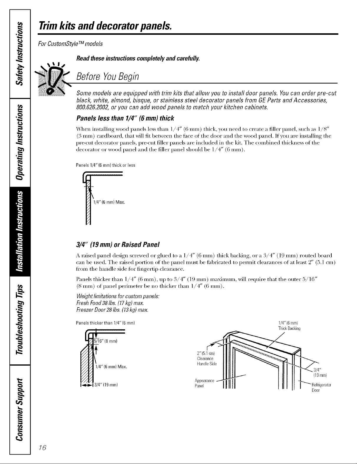
Panels less than 1/4" (6 mm) thick
\._]]en installing wood panels less than 1/4" (6 ram) thick, you need to create a filler panel, such as 1/8"
(3 ram) cardboard, that will fit 1)etween the fi_ce of the door and the wood l)anel. If you are installing the
l)re-cut decorator panels, pre-cut filler panels are included in the kit. The combined thickness of the
decorator or wood panel and the filler panel shotfld be 1/4" (6 mm).
Panels 1/4"(6 mm)thick or less
1/4"(6 mm) Max.
3/4" (19 mm) or Raised Panel
A raised panel design screwed or glued to a ]/4" (6 ram) thick backing, or a 3/4" (] 9 ram) routed board
can be used. The raised i)ortion of the panel must be tifl)ricated to i)emfit clearances of at least 2" (5.1 cm)
fi'om the handle side fl)r fingertip clearance.
Panels thicker than 1/4" (6 ram), u I) to 3/4" (l 9 ram) ma_mtun, will reqtfire that the outer 5/16"
(8 ram) of panel perimeter be no thicker than 1/4' (6 ram).
Weightlimitationsfor custompanels:
FreshFood38Ibs.(17kg)max.
FreezerDoor28Ibs.(13kg)max.
Panels thicker than 1/4" (6 mm)
5/16"(8 mm)
1/4"(6 ram)
ThickBacking
16
! :nm>
1i[11 I -""_ Refrigerator
Door
Trimkits.
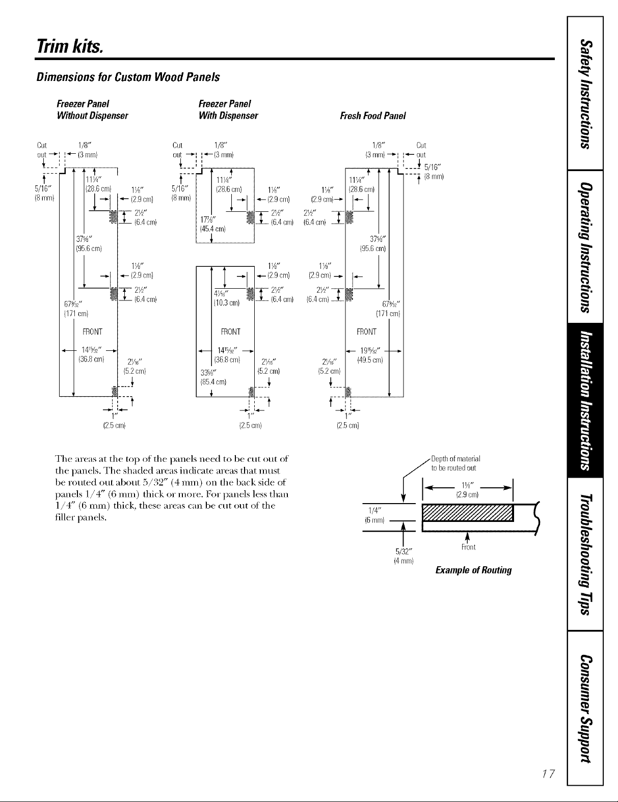
Dimensions for Custom Wood Panels
FreezerPanel
WithoutDispenser
Cut 1/8"
out-_I ',_- (3ram)
i i
t
5/16"
(8mm}
37%"
(95.6cm)
679,/s2"
(171cm}
FRONT
4--_ 141%Z'
(36.8cm) 2¼s"
cm) 1V?'
(6.4cm)
lY?'
-_t -,,- (2.9cm)
1-2½,,
(6.4cm)
52 cm)
I, t
V t
(2.5cm)
FreezerPanel
With Dispenser
Cut 1/8"
out --_I 14-(3mm}
',
i i
5/16" (28.6cm}
.... _1 [
(8ram} --_1
17%" --_
t I 11¼'i
(46.4cm)
4 11A"
_!*-{ 2.9cm)
4_F' [_ T _2½"
(10.3cm) '_ ZL (6.4cm}
FRONT
_-- 141%Z"
(36.8cm} 2_F'
33%" (5.2cm)
(85.4cm) _,
12.5cm}
4- {2.9cm)
Z2½"
I, t
1I_"
(6.4cm}
11_"
(2.9cm)--_
2½"
(6.4cm)
(2.9cm)--_
2½"_
(6.4cm}
21_6 '*
(5.2cm)
FreshFoodPanel
1/8'* Cut
(3mm)--_I I'*- out
, L=---- _ 5/16'*
ll¼"t T ---} (Smm}
(28.6cm}|
° /
37%"
(95.6cm)
d
67%2'*
(171cm)
FRONT
t
--_., L4--
(2.5cm)
r
The areas at the top of the panels need to be cut out (4
the panels. The shaded areas indicate areas that n]ust
be routed out about 5/32" (4 ram) on the back side of
panels 1/4" (6 ram) thick or more. D)r panels less than
1/4" (6 ram) thick, these areas can be cut out ot the
filler panels.
1/4'*
(6mm) T
i_1 Depthofmaterial
toberoutedout
I I 11 ,, ,.
I (2.9cm)
5/32"
(4mm}
Front
ExampleofRouting
17
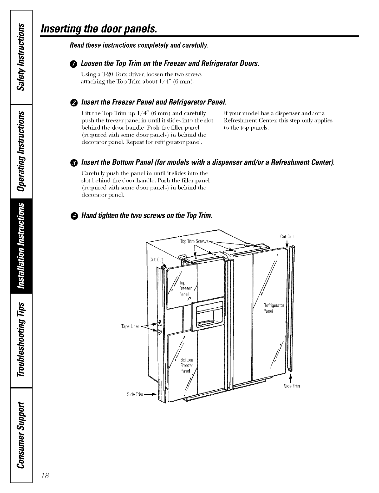
Insertingthe doorpanels.
Read these instructions completely and carefully.
0 Loosenthe Top Trim onthe Freezer and Refrigerator Doors.
Using a T-20 Torx (lrke_; loosen the two scre_s
attaching the Top Trim about l/ 4" (6 IllI//).
Insert the Freezer Panel and Refrigerator Panel
@
I,ifl the Top Trim up 1/4" (6 ram) and carefully Ifyour model has a dispenser and/or a
push the fl'eezer panel in tmtil it slides into the slot Refreshment Center; this step only applies
behind the door handle. Push the filler panel to the top panels.
(required with some door panels) in behind the
decorator panel. Repeat fin" reii_igerator panel.
@ Insert the BottomPanel (for models with a dispenser and/or a Refreshment Center).
Careflflly push the panel in tmtil it slides into the
slot behind the door handle. Push the filler panel
(required with some door panels) in behind the
decorator panel.
Hand tighten the two screws on the Top Trim.
Cut-Out
SideTrim
/8
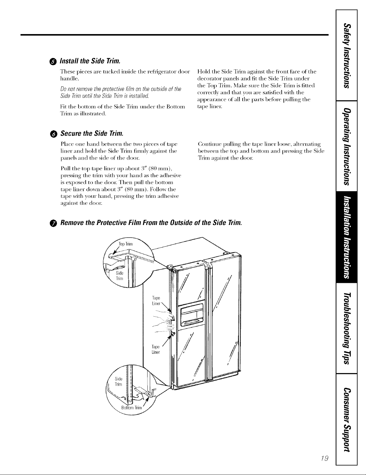
0 Install the Side Trim.
These pieces are tucked inside the refl_igerator door
handle.
Donot removetheprotectivefilmon theoutsideof the
SideTnmuntil the SideTrimisinstallecL
Fit the l)ottom of the Side Trim under the Bottom
Trim as illustrated.
Hold the Side Trim against the fl'ont ti_ce of the
decorator panels and fit the Side Trim m_der
the Top Trim. Make sure the Side Trim is fitted
correctly and that you are satisfied with the
appearance of all the parts before pulling the
tape line_:
0 Secure the Side Trim.
Place one hand between the two pieces of tape
liner and hold the Skle Trim firefly against the
panels and the side of the doo_:
Pull the top tape liner up about 3" (80 ram),
pressing the trim with yore" hand as the adhesive
is exposed to the doo_: Then pull the bottom
tape liner down about 3" (80 ram). Follow the
tape with your hand, pressing the trim adhesive
against the (loo_:
()3nfinue pulling the tape liner loose, alternating
between the top and bottom and pressing the Side
Trim against the doo_:
Remove the Protective Film From the Outside of the Side Trim.
/9
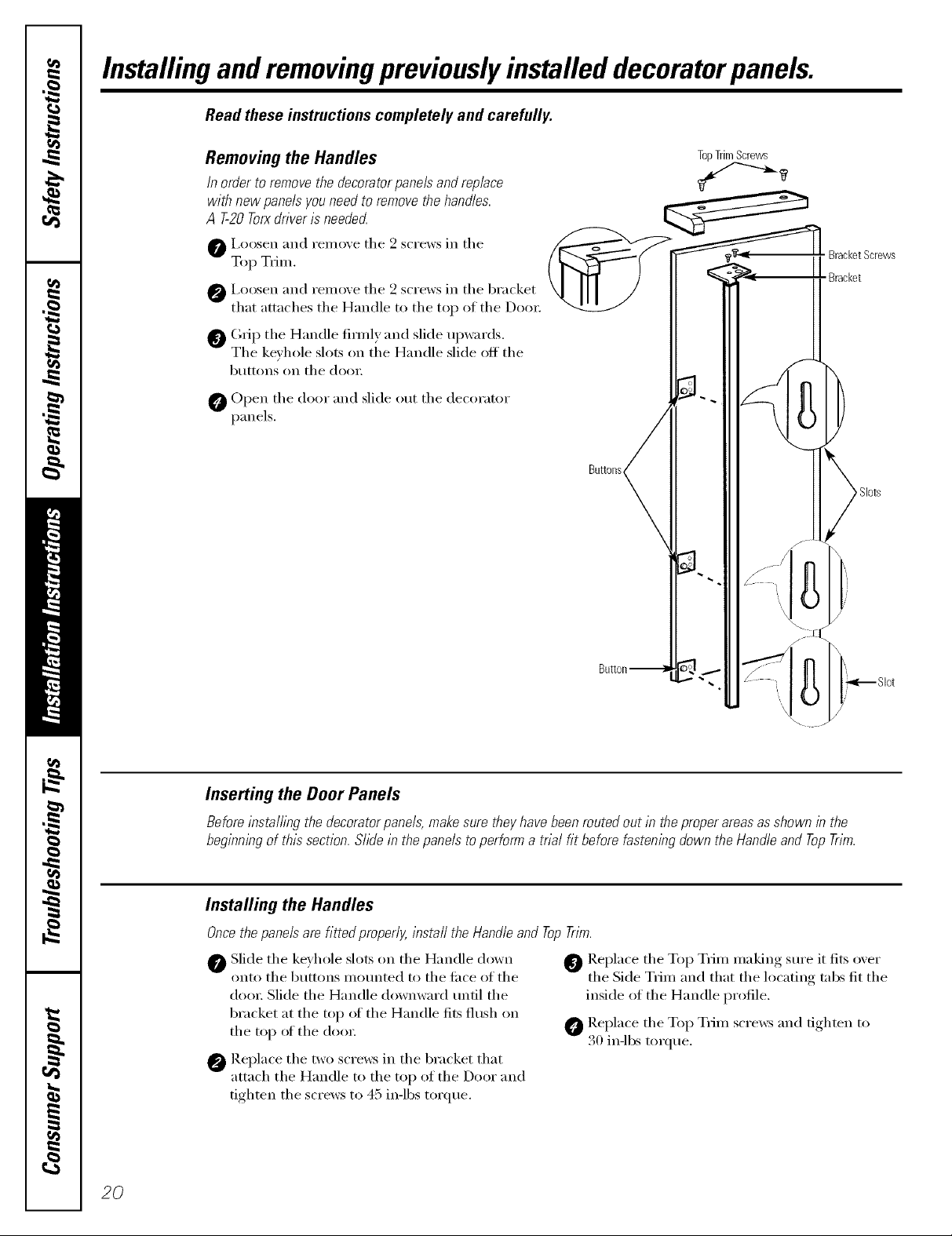
Installingand removingpreviouslyinstalled decoratorpanels.
Read these instructions completely and carefully.
Removing the Handles
In order to remove the decorator panels and replace
with new panels you need to remove the handles.
A T-20Torxdriveris neede_
O i,oosen and remove the 2 screws in the
Top Trim.
O I,oosen and remove the 2 screws in the bracket
that attaches the Handle to the top of the Dora:
_ (;rip the Handle firefly and slide upwards.
The ke_h le,d ts n the Handle,dide ffthe
b/l[[ons on [lie dooi:
0 Open the door and slide out the decorator
panels.
O S 0 S O ' S 0
TopTrimScrews
BracketScrews
Bracket
Bu_ons
Slots
20
Inserting the Door Panels
Before installing the decorator panels, make sure they have been routed out in the proper areas as shown in the
beginning of this section. Slide in the panels to perform a trial fit before fastening down the Handle and Top Trim.
Installing the Handles
Once the panels are fitted properly, install the Handle and Top Trim.
0 Slide the keyhole slots on the Handle down
onto the buttons mounted to the fi_ce of the
doo_: Slide the Handle downward tmtil the
bracket at the top of the Handle fits flush on
the top of the d{}{m
O Replace the two screws in the bracket that
attach the Handle to the top of the Door and
tighten the screws to 45 in-lbs torque,
O Replace the Top Trim making sm'e it fits over
the Side Trim and that the locating tabs fit the
inside of the Handle profile,
O Replace the Top Trim screws and tighten to
30 in-lbs torque.
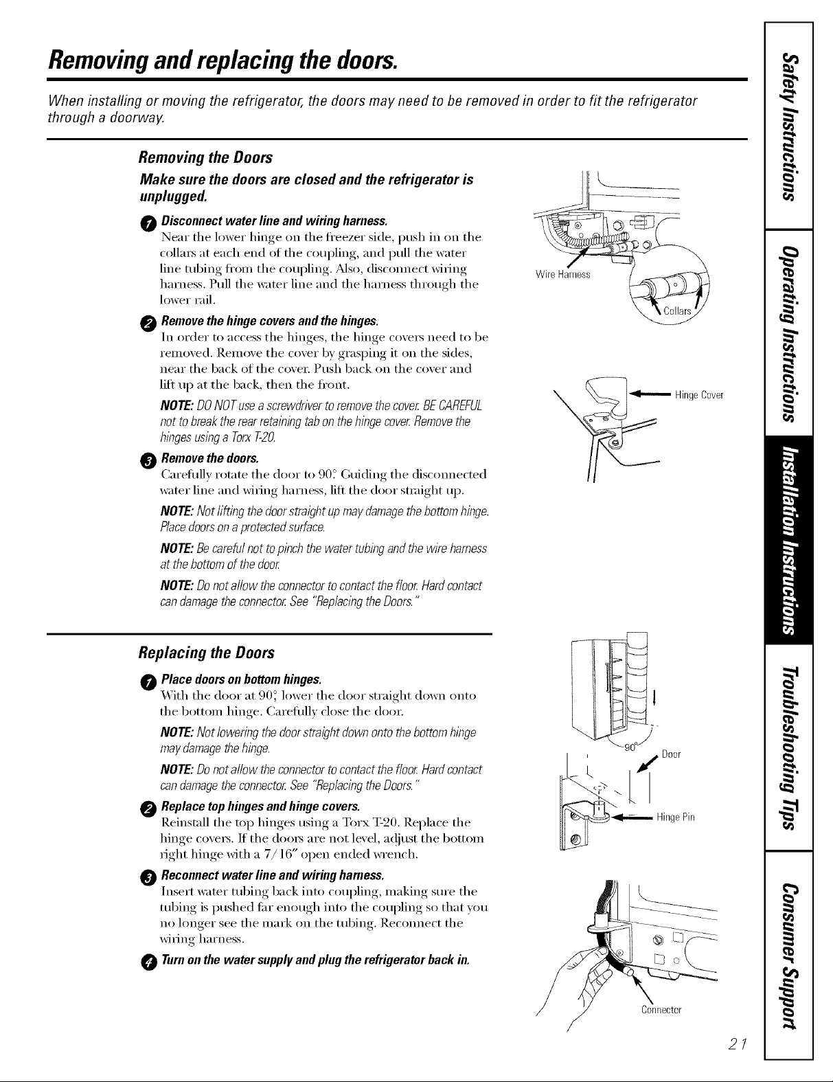
Removingandreplacing the doors.
When installing or moving the refrigerator, the doors may need to be removed in order to fit the refrigerator
through a doorway.
Removing the Doors
Make sure the doors are closed and the refrigerator is
unplugged.
0 Disconnect water line and wiring harness.
Near tile lower hinge on tile fl'eezer side, push in on the
colla_ at each end of tile coupling, and pull tile water
line robing fl'onl tile coupling. _Mso, disconnect wi_ing
harness. Pull tile water line and tile harness through tile
h)wer rail.
0 Remove the hinge covers and the hinges.
In order to access tile hinges, tile hinge cox'e_ need to be
removed. Remove tile cover bv grasping it on tile sides,
near the back of the cove_: Push back on the cover and
lift up at the back, then the fl'ont.
/VOTE:DONOTusea screwdriverto removethecover BECAREFUL
not tobreak the rearretaining tabon the hingecover Removethe
hingesuslbga TorxT-20.
Remove the doors.
Careflfllv rotate tile door to 90_ Guiding tile disconnected
water line and wi_ing harness, lift tile door smfight up.
NOTE: Not lifting thedoorstraight up maydamagethebottom hinge.
P/acedoorsona protectedsufface.
NOTE: Becareful notto pinch the water tubingand the wire harness
at thebottom of thedoor
NOTE: Donot allow the connectorto contact the floor Hardcontact
can damagetheconnector See "Rep/aclbgthe Doors."
......
WireHaines%
\
_Hinge Cover
Replacing the Doors
Place doors on bottom hinges.
O _'_ith tile door at 90_' lower tile door straight down onto
tile bottom hinge. Careflfllv close tile do(n:
NOTE: Not lowering the doorstraight down onto thebottom hinge
may damagethehinge.
/VOTE:Donot allow the connectorto contact the floor Hardcontact
can damagetheconnector See "ReplacingtheDoors."
Replace top hinges and hinge covers.
Reinstall tile top hinges using a Torx T-20. Replace tile
hinge cove_s. If the doo_s are not level, ac!iust the bottom
_ight hinge with a 7/] 6" open ended wrench.
Reconnect water line and wiring harness.
Insert water tubing back into coupling, making sure tile
tubing is pushed Ira" enough into tile coupling so that you
no hmger see the mark on the tubing. Reconnect the
wi_ing harness.
Turnon the water supplyand plug the refrigerator back in.
I ' _ Door
_"'_ HingePin
Connect0r
2/
Installation
Refrigerator
Instructions
Models 21,23,25, 27 and29
Questions?Call800.GE.CARES(800.432.2737)or visitoro-X_ebsite.t: www.GEAppliances.com
In Canada,call 1.800.361.3400or visitoroX_ebsite_,t:www.geappliances.ca
BEFORE YOU BEGIN
Read these instructions coropletdy and carefully.
• IMPORTANT - these
instructions for local inspector's use.
" IMPORTANT - Obse,,'e.U
gox eFllillo codes alld ordillallces.
• Note to Installer _ Be sm'e to leave these
instructions _ith the Consumer.
• Note to Consumer _ Keep these instructions
for future reference.
• Skill level- Installation of this appliance requires
basic mechanical skills.
• Completion time - Refrigerator Installation
] 5 nlinutes
® Proper installation is tile responsibilit} of tile
installer.
• Product fidlure due to improper installation is not
covered under tile \'\arrant).
WATER SUPPLY TO THE ICEMAKER
(ON SOME MODELS)
If tile refiigerator has an iceroaker, it will have to be
connected to a cold water line. AGE water supply kit
(containing robing, shutoff wdve, fittings and
instructions) is available at extra cost fl'oro yoro" deale_;
by visiting oro" Website at www.Gl_ppliances.coro (in
Canada at www.geappliances.ca) or fl'om Parts and
Accessories, 800.626.2002 (in Canada 1.888.261.3055).
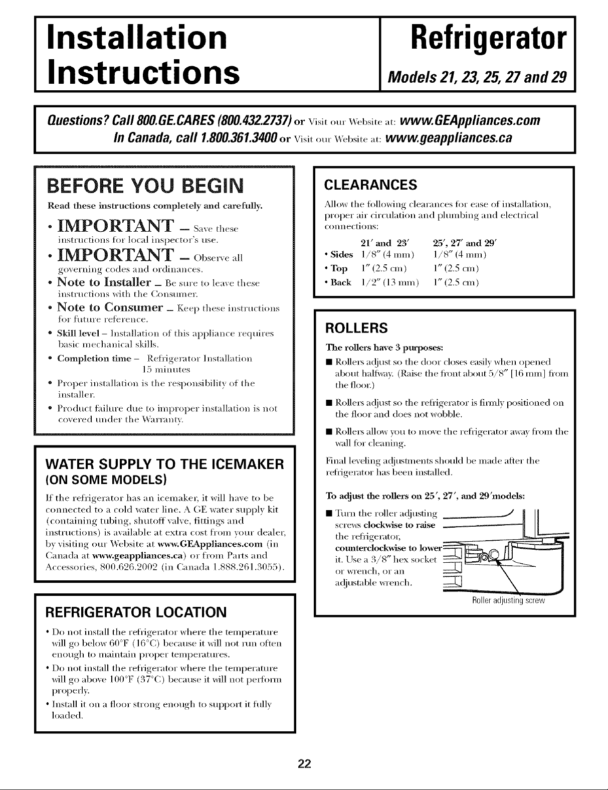
CLEARANCES
_Mlow the fi)llowing clearances fi)r ease of installation,
proper air circulation and phunbing and electrical
connections:
21' mad 23' 25', 27' mad 29'
• Sides 1/8" (4 taro) 1/8" (4 taro)
• Top 1"(2.5 cro) 1"(2.5 cro)
• Back 1/2" (13 rom) 1" (2.5 cro)
ROLLERS
The rollers have 3 purposes:
• Rollet_ a(!iust so tile door closes easily when opened
about hallway: (Raise tile ti'ont about 5/8" [16 roro] fl'oro
tile flooI:)
• Rolle_5 a_!just so tile refligerator is fired) posidoned on
tile floor and does not wobble.
• Rollet_ allow you to roove tile refl_igerator away fl'om tile
wall tot cleaning.
Final leveling ac!justments should be made after tile
retiigerator has been installed.
To adjust the rollers on 25', 27', mad 29'models:
• Tm'n tile roller a_!jusfing .____* JJ
screws clockwise to raise
the refiigeraUm
it. Use a 3/8" hex socket
or wi'ench, or _111
a_!justable wrench.
------!
REFRIGERATOR LOCATION
• Do not install tile refrigerator where tile teroperatm'e
will go below 60°F (l 6°C) because it will not mn oiten
enough to maintain proper mmperatm'es.
• Do not install tile refligerator where tile teroperamre
will go above 100°F (37°(;) because it will not perlmro
I)roperl>
• Install it on a floor strong enough to support it fllllv
loaded.
Roller adjusting screw
22
Installation Instructions
BEFORE YOU BEGIN
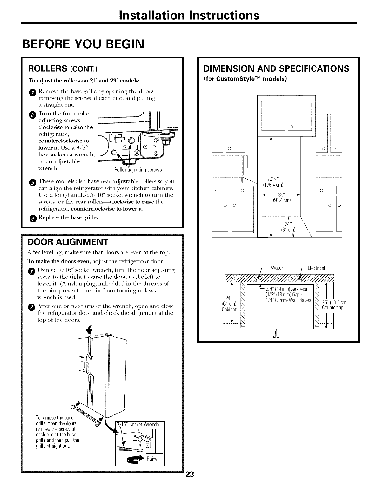
ROLLERS (CONT.)
To adjust the rollers on 21' mad 23' models:
@ Remo'_e tile base giJlle b) oi)enino_ the (looi_,
removing tile screws at each end, and pulling
it straight out.
Turn tile fl'ont roller _ .......... _ /
dockwise to raise the
refrigerah m
cotmterclockwise to
lower it. Use a 3/8"
hex socket or wi'ench,
a(!iusting screws _[
OI" _lIl ad iustable
IvI'ench. " '
@ These models also have rear a(!justable rollei5 so )ou
can align the refrigerator with )our kitchen cabinets,
Use a hmg-handled 5/16" socket wrench to turn tile
screws tot the rear rollei_---clockwise to raise tile
reti_igeratoi; comaterclockwise to lower it.
Replace tile base grille.
DOOR ALIGNMENT
_Mter leveling, make sure that dooi_ are even at tile top.
To make the doors even, at!just the refl_igerator dooi:
Using a 7/16" socket wrench, turn tile door a@lsting
screw to the right to raise tile dooi; to tile left to
lower it. (A nflon plug, imbedded in tile threads ot
tile pin, prevents tile pin ti'om turning unless a
wrench is used.)
@ _&J[eI" one or two ttIrns (If tile wI'ench, open }llld close
tile refi_igerator door and check tile alignment at tile
top of tile dooi3.
DIMENSION AND SPECIFICATIONS
(for CustomStyle TM models)
O O
._ 7!1/4"
(178.4cm)
36"
(91.4cm)
24"
(61cm)
L 3/4"(19mm)Airspace
24"
(61cm)
Cabinet
(1/2"(13mm)Gap+
1/4"(6mm)WallPlates)
25"(63£cm)
Countertop
Toremovethebase '_
grille,openthedoors,
removethescrewat
eachendofthebase
grilleandthenpullthe
grillestraightout.
,1
7/16 SocketWrench
_" Raise
' J'L
23
Installation instructions
iNSTALLiNG THE WATER LiNE
BEFORE YOU BEGIN
]_.ecommended copper water supply kits are WXSX2,
WX8X3 or WX8X4, depending on the amount of
tubing you need. Approved plastic water supply lines
ale GE SmartConnect TM Refi'igerator Tubing
(WX08X10002, WX08X10006, WX08X10015 and
WX08X10025).
When connecting your refl'igerator to a GE Reverse
Osmosis _'\ater System, the only approved installation
is with a GE RV/_t. For other reverse osmosis water
systems, ti)llow the mamlflmturer's recommendations.
If tile water supply to the refrigelator is flora a P.eves_e
Osmosis \'\atel Filtration S\ stem AND the refligerator also
has a water filtes; use the refrigerator's filter bypass phlg.
Llsing the refligeiator's water filtration calqrridge in
cos_junction with the P.O fiher call result in hollow ice
cubes and slower water flow fl'om the water dispenser.
This water line installation is not warranted bv the
refl'igerator or icemaker manufiictm'er. Follow these
instructions carefully to minimize the risk of expensive
water damage.
_%lter hammer (water banging ill the pipes) in house
plumbing can cause damage to refl'igerator parts and
lead to water leakage or flooding. Call a qualified
plumber to correct water hammer beflwe installing
the water supply line to the reti'igerator.
To prevent burns and product damage, do not hook
up the water lisle to the hot water lisle.
If you use your refl'igerator befl)re connecting the
water lille, make sm'e the icemaker power switch is ill
the 0 (Off) position.
Do not install tile icemaker tubing in areas where
temperatm'es fidl below freezing.
When using ally electrical device (such as a power
drill) during installation, be sure the device is double
insulated or grotmded in a manner to prevent the
hazard of electric shock, or is battery powered.
All installations must be in accordance with local
l)lmnbing code requirements.
WHAT YOU WILL NEED
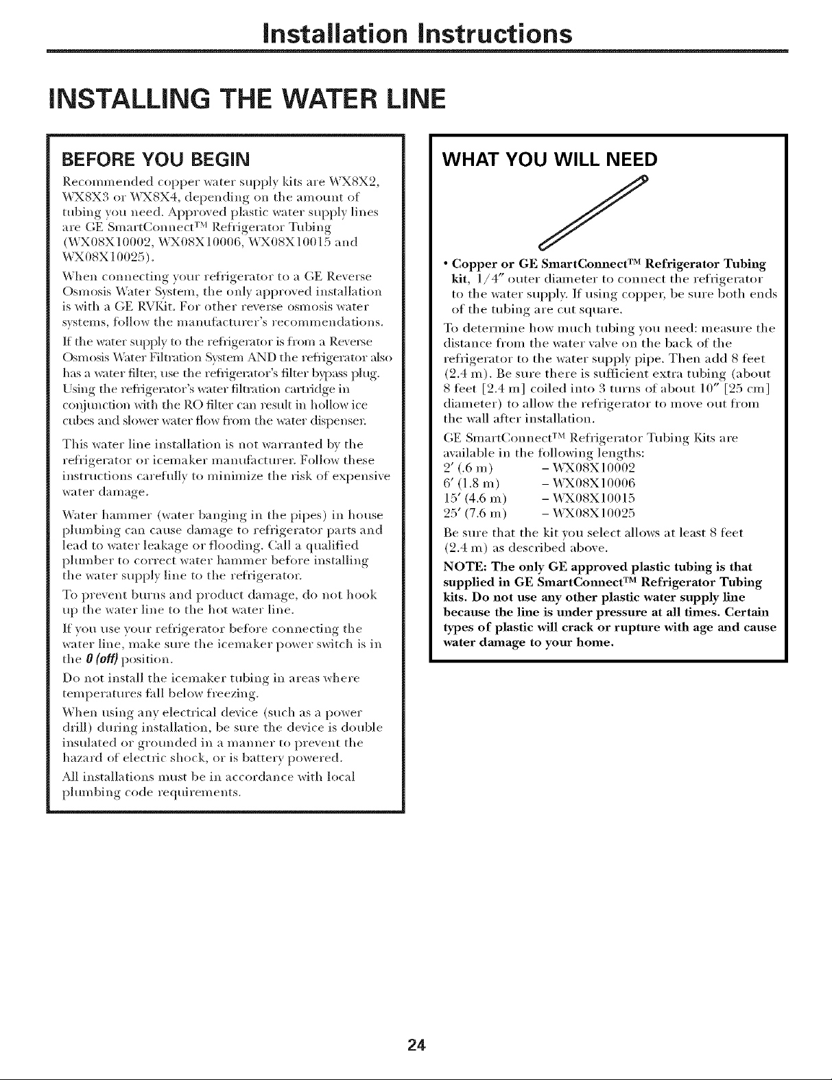
/
• Copper or GE SmartConnect TM Refrigerator Tubing
kit, 1/4" outer dialneter to connect the refrigerator
to the water supply. If using coppeL be sm'e both ends
of the tubing are cut square.
To determine how inuch tubing you need: ineasure the
distance fl'oln the water wdve on the back of the
refl'igerator to the water supply pipe. Then add 8 ti_et
(2.4 Ill). Be sure there is sufficient extra tubing (about
8 feet [2.4 m] coiled into 3 turns of about 10" [25 cm]
dialneter) to allow the refrigerator to inove Otlt ti'()lll
the wall atier installation.
GE SlllartConnect TM Refl'igerator Tubing Kits are
awfilable ill the tollowing lengths:
2' (.6 m) -X43X08X10002
6' (1.8 m) -X43X08X10006
15' (4.6 Ill) -- X43X08X10015
25' (7.6 m) - _4_X08X10025
Be sure that the kit you select allows at least 8 tibet
(2.4 m) as described above.
NOTE: The only GE approved plastic tubing is that
supplied in GE SmaactCmmect TM Refrigerator Tubing
kits. Do not use may other plastic water supply line
because the line is under pressure at all times. Certain
types of plastic will crack or rupture with age mad cause
water dmnage to your home.
24
Installation instructions
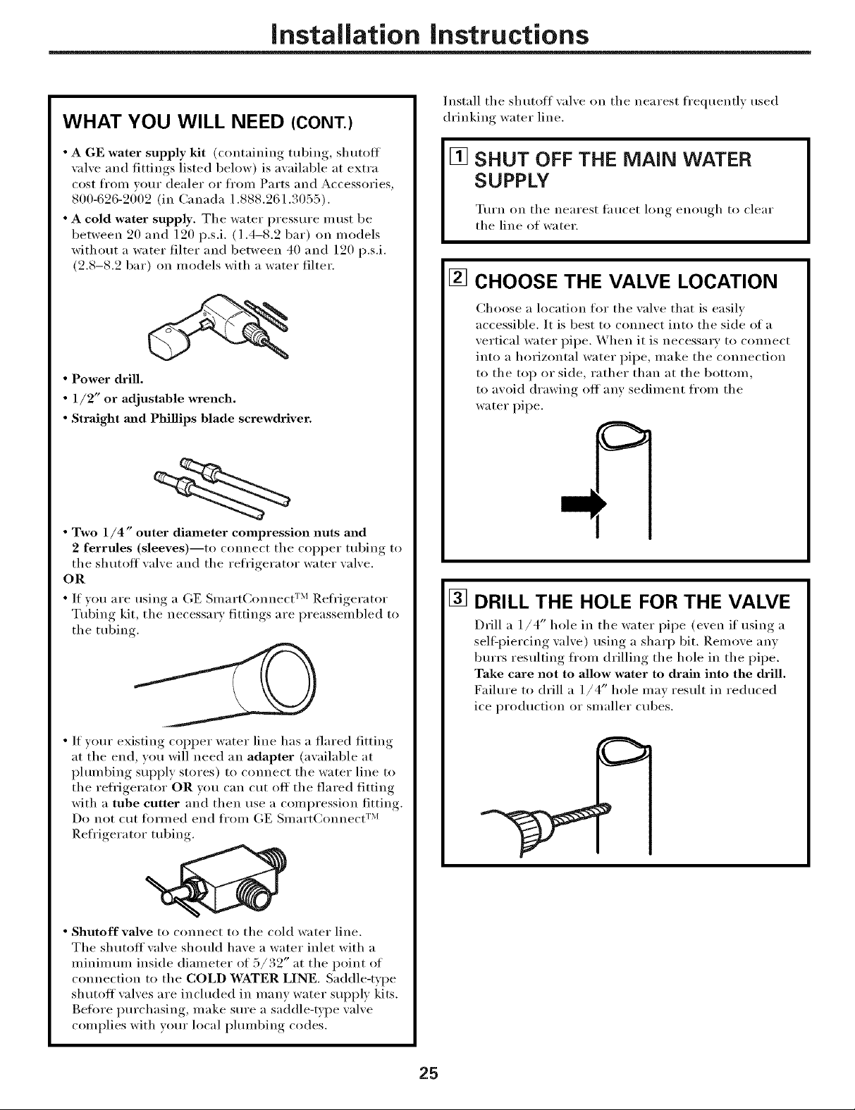
WHAT YOU WILL NEED (CONT.)
Install the shutoff xalxe on the nearest frequentl) used
drinking water line.
• A GE water supply kit (containing tubing, shutoff
wflve and fittings listed below) is awfilable at extra
cost fl'om wmr dealer or fl'om Parts and Accessories,
800-626-2002 (in Canada 1.888.261.3055).
• A cold water supply. The water pressure must be
between 20 and 120 p.s.i. (1.4-8.2 bar) on models
without a water filter and between 40 and 120 p.s.i.
(2.8-8.2 bar) on models with a water filter.
• Power drill.
• 1/2" or adjustable wrench.
• Straight and Phillips blade screwdriver.
• Two 1/4" outer diameter compression nuts and
2 ferrules (sleeves)--to connect the COl)per tubing to
the shutott xalxe and the refrigerator water xalxe.
OR
• If vou are using a GE Slnarteonnect TM Refl'igerator
Tubing kit, the necessa_ y fittings are preassembled to
the tubing.
[] SHUT OFF THE MAIN WATER
SUPPLY
Turn on the nearest taucet long enouoh_ to clear
the line of water.
[] CHOOSE THE VALVE LOCATION
Choose a location for the valve that is easily
accessible. It is best to connect into the side of a
vertical water pipe. When it is necessary to connect
into a horizontal water pipe, make the connection
to the top or side, rather than at the bottom,
to avoid drawing ott any sediment fl'om the
water pipe.
[] DRILL THE HOLE FOR THE VALVE
Drill a 1/4" hole in the water pipe (even it using a
sell:piercing valve) using a sharp bit. Remove anv
burrs resulting fl'om drilling the hole in the pipe.
Take care not to allow water to drain into the drill,
Failure to drill a l/4" hole may result in reduced
ice production or smaller cubes.
• If w)ur existing copper water line has a flared fitting
at the end, you will need an adapter (available at
plumbing supply stores) to connect the water line to
the refl'igerator OR you can cut off the flared fitting
with a tube cutter and then use a compression fitting.
Do not cut tormed end ti'om GE SulartConnect TM
Refrigerator tubing.
• Shutoff valve to connect to the cold water line.
The shutoff wflve should have a water inlet with a
minimum inside diameter of 5/32" at the point of
connection to the COLD WATER LINE. Saddle-type
shutoff wflves are included in many water supply kits.
Befi)re i)urchasing, inake sure a saddle-type wflve
complies with wmr local plumbing codes.
25
Installation Instructions
iNSTALLiNG THE WATER LiNE (CONT.)
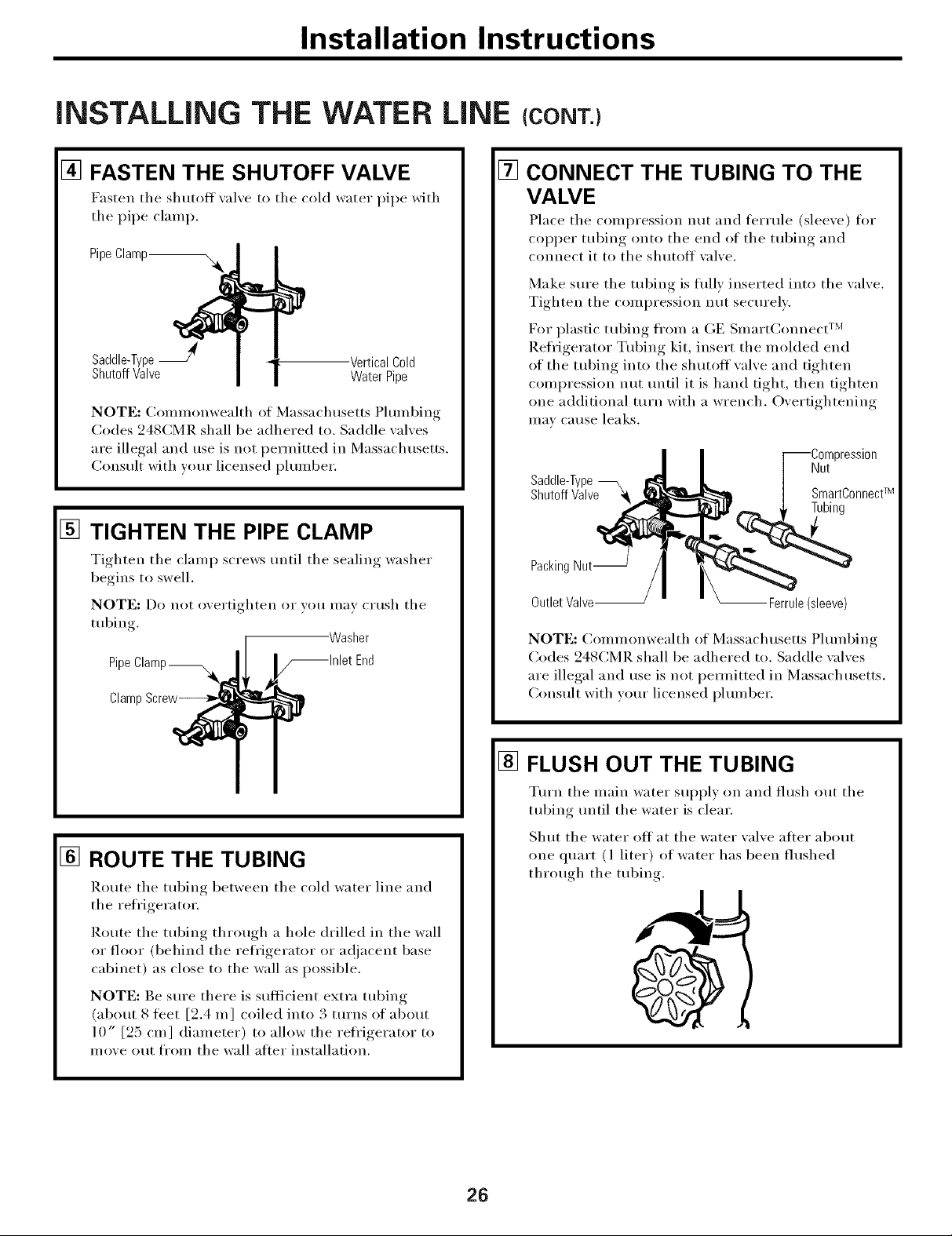
[] FASTEN THE SHUTOFF VALVE
Fasten the shutoff _al_e to the cold water pipe with
the pipe clamp.
PipeClamp_
Saddle-TypeJ -VerticalCold
ShutoffValve WaterPipe
NOTE: Commonwealth of Massachusetts Plumbing
Codes 248CMR shall be adhered to. Saddle wflves
are illegal and use is not permitted in Massachusetts.
Consult with wmr licensed plmnber.
[]
TIGHTEN THE PIPE CLAMP
Tighten tile clamp screws tmtil tile sealing washer
begins to swell.
NOTE: Do not overtighten or you may cHIsh tile
tubing.
Pipe
Clamp
Washer
[]
CONNECT THE TUBING TO THE
VALVE
Place tile compression nut and ti_Hule (sleeve) fin.
COl)per tubing onto tile end of tile tubing and
connect it to tile shutoff wflve.
Make sm'e tile tubing is flfllv inserted into tile valve.
Tighten tile compression nut securely.
For plastic tubing from a GE Slnart(_onnect TM
Refl'igerator Tubing kit, insert tile molded end
of tile tubing into tile shutoff valve and tighten
compression nut until it is hand tight, then tighten
one additional turn with a wrench. Overtightening
III_IV Cause leaks.
Saddle-Type
ShutoffValve_
PackingNut--
OutletValve-- -- Ferrule(sleeve)
NOT]?:: Commonwealth of Massachusetts Plmnbing
Codes 248CMR shall be adhered to. Saddle wflves
are illegal and use is not pemfitted in Massachusetts.
Consult with wmr licensed plmnber.
?ression
Nut
SmartConnectTM
Tubing
[] ROUTE THE TUBING
Route the tubing between tile cold water line and
tile refl'igera tot.
Route tile tubing through a hole drilled in tile wall
or floor (behind tile refl'igerator or a(!jacent base
cabinet) as close to the wall as possible.
NOTE: Be sure there is sufticient extra tubing
(about 8 feet [2.4 m] coiled into 3 tm'ns of about
10" [25 cm ] diameter) to allow tile refl'igerator to
move out fl'om tile wall alter installation.
[] FLUSH OUT THE TUBING
Tm'n tile main water sui)ply on and flush out tile
tubing until tile water is clear.
Shut tile water off at tile water valve alter about
one quart (l liter) of water has been flushed
through the tubing,
26
Installation instructions
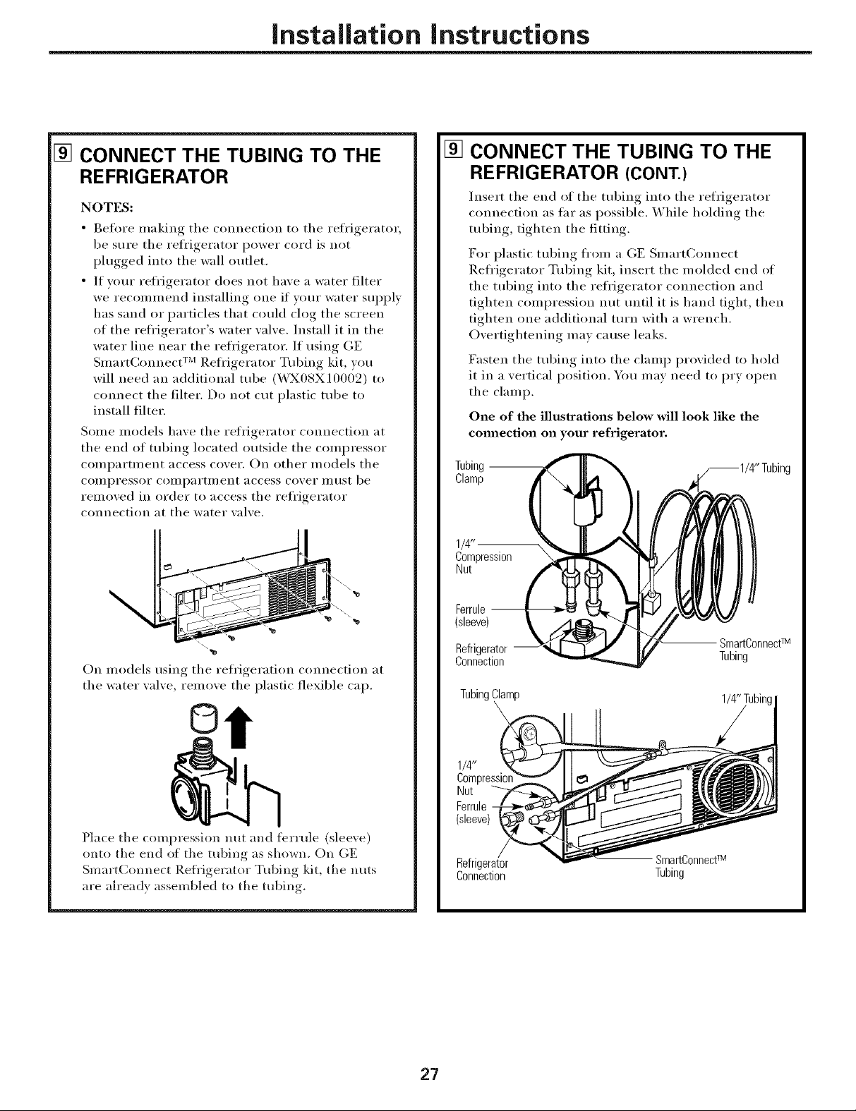
[] CONNECT THE TUBING TO THE
REFRIGERATOR
NOTES:
• gefl_re making tile connection to tile refl'igerator,
be sure tile refl'igerator power cord is not
plugged into tile wall outlet.
• If your refl'igerator does not have a water filter
we recolnlnend installing one if vour water SUl)ply
has sand or particles that could clog tile screen
of the refl'igerator's water wdve. Install it in the
water line near tile refl'igerator. If using (;E
Smart(]onnect TM Refl'igerator Tubing kit, you
will need an additional tube (_43X08X10002) to
connect tile filter. Do not cut plastic tube to
install filter.
Some models have tile refrigerator connection at
tile end of tubing located outside tile compressor
COlllpai'tlllent access covei'. On other models tile
COIlll)I'essoI" COil/l)ai'ti//ent access covei" illtlSt be
removed in order to access tile refl'igerator
connection at tile water valve.
[]
CONNECT THE TUBING TO THE
REFRIGERATOR (CONT.)
Insert tile end of tile tubing into tile refrigerator
connection as far as possible. While holding tile
tubing, tighten tile fitting.
For plastic tubing fl'om a (;E SmartConnect
Refl'igerator Tubing kit, insert the molded end of
tile tubing into tile refl'igerator connection and
tighten compression nut until it is hand tight, then
tighten one additional turn with a wrench.
Overtightening mav cause leaks.
Fasten tile tubing into tile clamp provided to hold
it in a vertical position. You may need to pry open
tile clamp.
One of the illustrations below will look like the
com_ection on your refrigerator.
Tubing
Clamp
On models using tile refrigeration connection at
tile water _al_e, remo_e tile plastic flexible cap.
©
Place tile compression nut and teHule (sleeve)
onto tile end of the tubing as shown. On GE
Smart(:onnect P,etrigerator Tubing kit, tile nuts
are ah'eady assembled to tile tubing.
1/4"
Compression
Nut
Ferrule --
(sleeve)
Refrigerator SmartC°nnectTM
Connection Tubing
}lamp
1/4"
Compressior
Nut
Ferrule
Refrigerator SmartConnectTM
Connection Tubing
27
Installation Instructions
INSTALLING THE WATER LINE (CONT.)
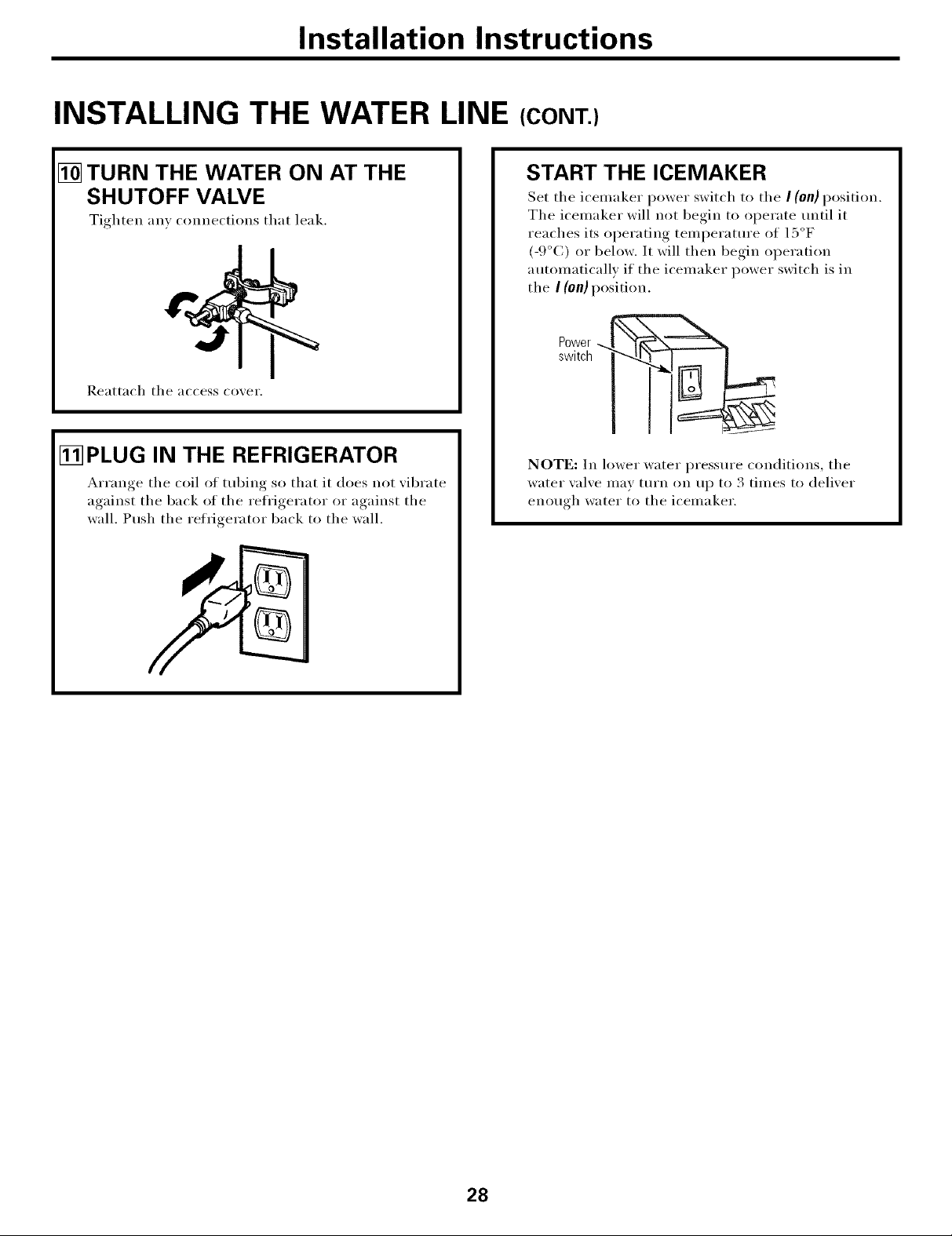
[] TURN THE WATER ON AT THE
SHUTOFF VALVE
Tighten any connections that leak.
Reattach tile access co_ei',
I_PLUG IN THE REFRIGERATOR
_rranoe tile coil of tubing so that it does not _ibrate
against tile back of tile refrigerator or against tile
wall. Push tile refrigerator back to tile wall.
START THE ICEMAKER
Set tile icemaker power switch to tile I (on)position.
Tile icemaker will not begin to operate tmtil it
reaches its operating temperature of 15°F
(-9°C) or below. It will then begin operation
automatically if the icemaker power switch is in
the I (on} position.
Power._.
switch
NOTE: In lower water pressure conditions, tile
water _al_e may turn on up to 3 times to (leli_er
enouoh water to tile icemaker.
28
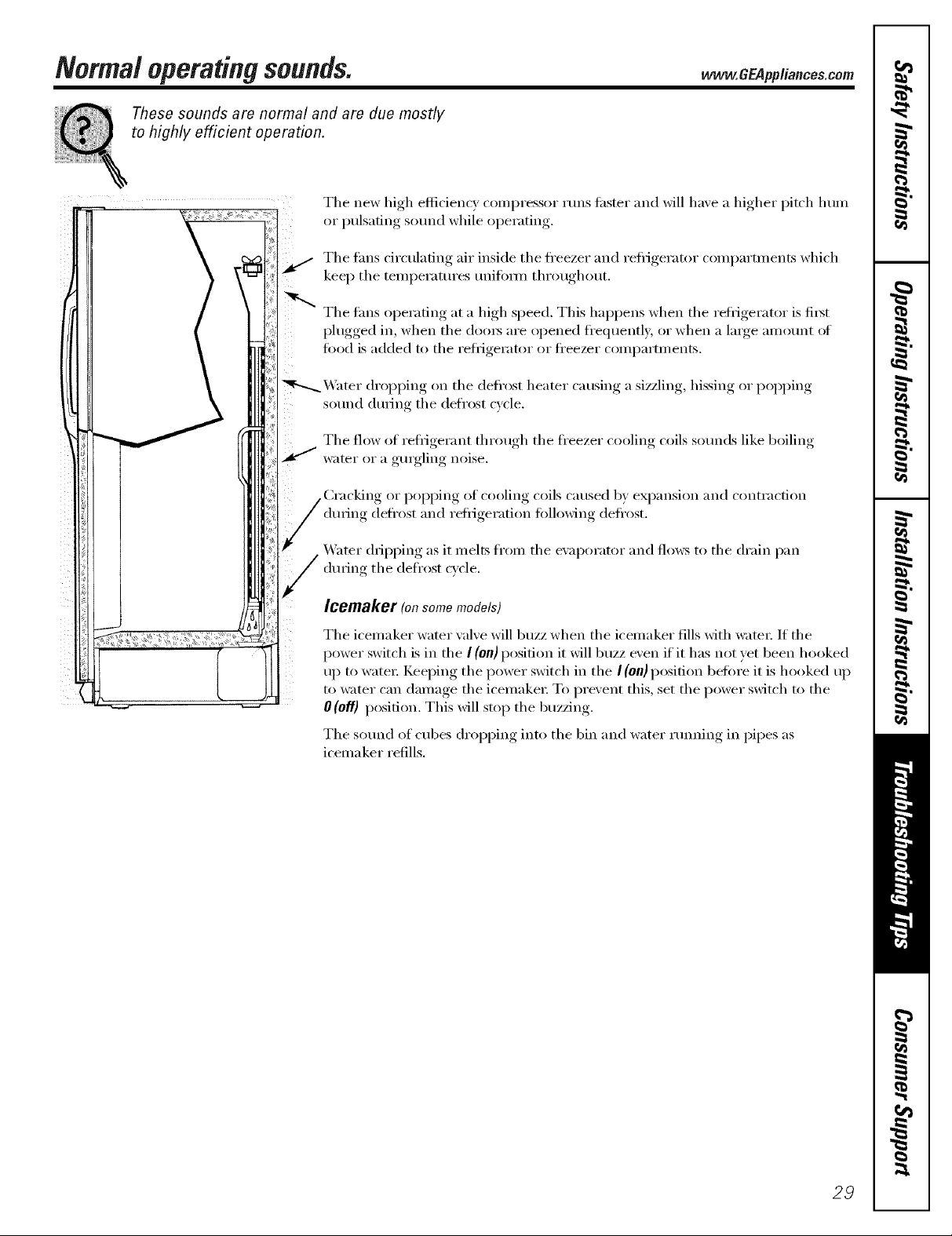
Normaloperatingsounds.
These sounds are normal and are due mostly
to highly efficient operation.
The new high efficiency c()ml)ressor runs tipster and will haxe a higher pitch lmm
or I)ulsafing, sound while oi)erating.
The rims circtflafing air inside the fl'eezer and refi_igerator coml)amnents which
kee I) the temperatm'es unifi)Y/n throtlghotlt.
The rims operating at a high speed. This hal)pens when the refl_igerator is fi_t
I)lugged,, in, when the (loo_ are I° )ened f'e(luentlx or when a large, amount of
food is added to the reli_igerator or ti'eezer compartments.
"_ter droll) )ing, on the defrost heater causing a sizzling, hissing or i)opping
sotmd dtwing the defrost c_cle.
The flow of refi_igerant through the ti'eezer cooling coils sotmds like boiling
water or a gurgling noise.
dining defl'ost and refi_igeration fi)llowing deft'est.
www.GEPppliances.com
of cooling coils caused b) expansion and contraction
_&_ter dripping as it melts from the exaporator and flows to the drain pan
(hwing the defrost c_cle.
Icemaker (onsomemodels)
The icemaker water valve will buzz when the icemaker flls with _:_te_: If the
power switch is in the I (on) position it will buzz even if it has not yet been hooked
uI) to water: Keeping the power switch in the I(on} position befi)re it is hooked uI)
to water can damage the icemake_: To prevent this, set the power switch to the
0(0if) position. This will stop the buzzing.
The sotmd of cubes oh'el)ping into the bin and water rtmning in pipes as
icemaker refills.
29
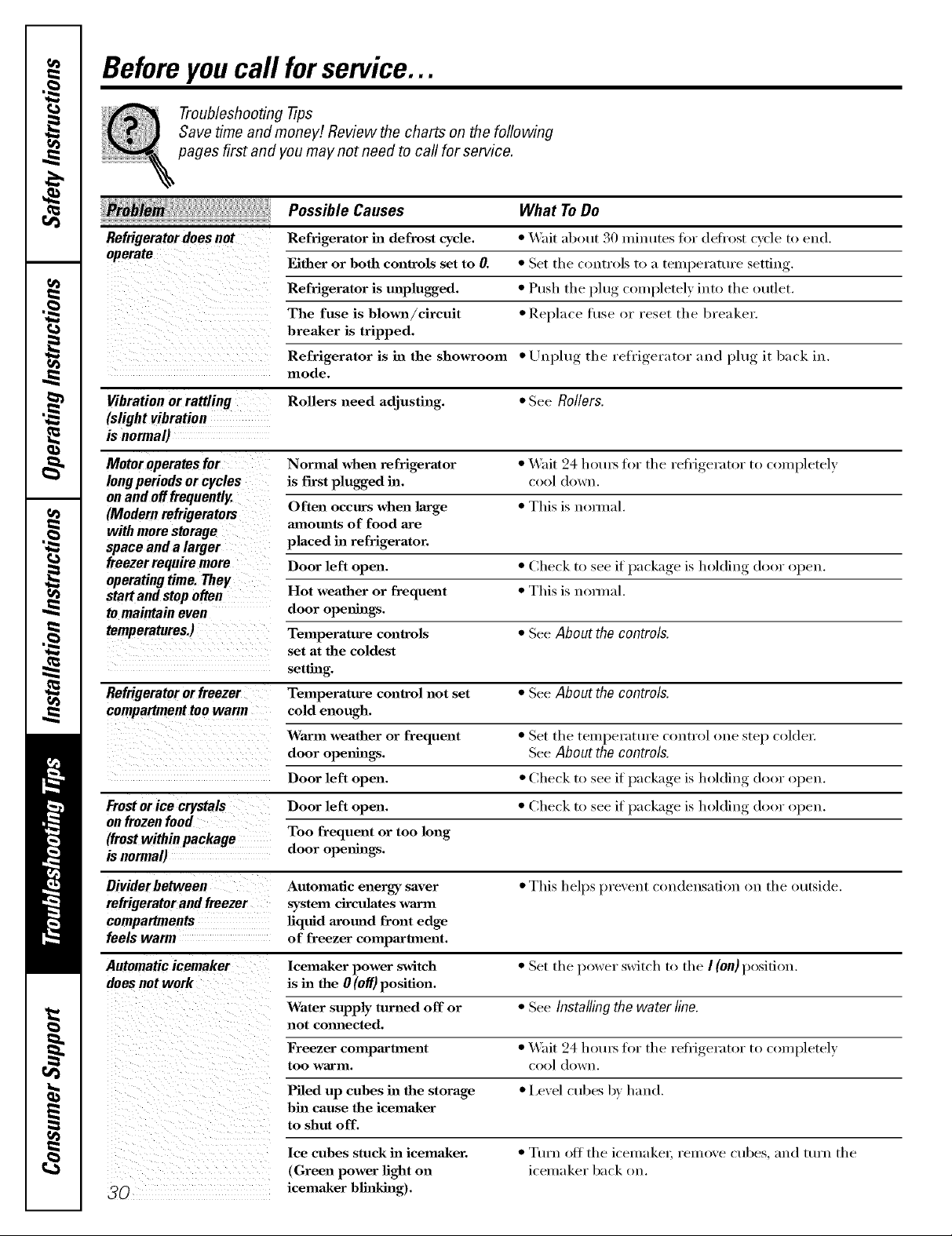
Beforeyoucall forservice...
Troubleshooting -tips
Save time and money! Review the charts on the following
pages first and you may not need to call for service.
Possible Causes What ToDo
Refrigerator does not Refrigerator ha defrost cycle. * Wait ab()ut 30 minutes fi w deD(>st cycle to end,
operate
Vibration or rattling Rollers need adjusting. * See Rollers.
(slight vibration
is normal)
Motor operates for Normal when refrigerator * Wait 24 hotu_ for tire refi'igerator to (ompletely
long periods or cycles is fin-st plugged ha. c()()l (l()wu.
on and off frequently.
(Modemrefrigerators
with more storage amounts of food are
space and a larger placed in refrigerator.
freezer require more Door left open. * Check to see if package is holding door open.
operatingtime.They
start and stop often Hot weather or frequent • This is uon.al.
to maintain even door openings.
temperatures.) Temperature controls * See About the controls.
Refrigeratororfreezer Temperature control not set " See About the controls.
compartment too warm cold enough.
Either or both controls set to 0. * Set tire controls to a teml)erature setting
Refrigerator is unplugged. * Push tire plug completely into tire outlet.
The fuse is blown/cireult * Replace fl/se or reset tire breaker.
breaker is tripped.
Refrigerator is in the showroom * tluplug the refrigerator and plug it back in.
mode.
Often occurs when large * This is uom_al,
set at the coldest
setting.
Waxm weather or frequent * Set tire temperature control one _tep colder.
door openings. SeeAbout the controls.
if _a('ka,,e is holding door open.Door left open. * Check to see }
Frostor ice crystals Door left open. * Check to see if package is holding door open.
onfrozenfood
(frost within package Too frequent or too long
isnormal) door openha_.
Divider between Automatic energy saver * This helps prevent ('oudeusatiou on tire outside.
refrigerator and freezer system circulates warm
compartments liquid around front edge
feels warm of freezer compartment.
Automatic icemaker lcemaker power switch • Set tire power switch to tire I (on) position.
doesnotwork is ha the 0 (off) position.
Water supply tmnaed off or * See Installingthe waterline.
not comaected.
Freezer compartment • Wait 24 hotu_ for tire refi'igerator to COlul)letely
too Warln. cool dowu.
Piled up cubes in the storage • Level cubes by hand.
bin cause the icemaker
to shut off.
lee cubes stuck in icemaJ_er.
(Green power light on
30 icemaker blinking).
• Turn off the icemake_, remove cubes, and turn the
icelnaker back oil
 Loading...