

Page 1
g
GE Consumer Home Services T raining
TECHNICAL SERVICE GUIDE
Arctica Side-By-Side Refrigerator
Inverter Compressor
Low Noise - High Performance
MODEL SERIES:
PSH23SGNAFBS
PUB # 31-9090 02/02
Page 2

!
IMPORTANT SAFETY NOTICE
The information in this service guide is intended for use by
individuals possessing adequate backgrounds of electrical,
electronic, and mechanical experience. Any attempt to repair a
major appliance may result in personal injury and property
damage. The manufacturer or seller cannot be responsible for the
interpretation of this information, nor can it assume any liability in
connection with its use.
WARNING
To avoid personal injury, disconnect power before servicing this
product. If electrical power is required for diagnosis or test
purposes, disconnect the power immediately after performing the
necessary checks.
RECONNECT ALL GROUNDING DEVICES
If grounding wires, screws, straps, clips, nuts, or washers used
to complete a path to ground are removed for service, they must
be returned to their original position and properly fastened.
GE Consumer Home Services Training
Technical Service Guide
Copyright © 2002
All rights reser ved. This service guide may not be reproduced in whole or in part
in any form without written permission from the General Electric Company.
Page 3

Table of Contents
Table of Contents
Introduction ..........................................................................................................2
Specifications.......................................................................................................3
Nomenclature ....................................................................................................... 4
Component Locator Views..................................................................................5
Principals of Refrigeration .................................................................................. 6
Phases of Refrigeration .................................................................................. 6
Dryer..................................................................................................................8
Filter .................................................................................................................. 8
Capillary ............................................................................................................9
Heat Exchanger ................................................................................................ 9
Refrigeration System ......................................................................................... 10
System Pressure............................................................................................ 11
Refrigerant Charge ........................................................................................ 11
Inverter Compressor ..................................................................................... 12
Inverter ........................................................................................................... 14
Adaptive Defrost ................................................................................................ 16
Fans.....................................................................................................................18
Evaporator Fan ...............................................................................................18
Condenser Fan ............................................................................................... 20
Fresh Food Fan .............................................................................................. 21
Main Control Board ........................................................................................... 22
Diagnostics ......................................................................................................... 29
Compressor Not Running Flowcharts ......................................................... 29
Fresh Food Warm - Freezer Normal Flowchart...........................................30
Fresh Food Too Cold - Freezer Normal Flowchart ..................................... 31
Fresh Food Warm - Freezer Warm Flowchart ............................................. 32
Freezer Warm - Fresh Food Normal Flowchart...........................................33
Refrigerator Dead - No Sound, No Cooling Flowchart .............................. 34
Damper Not Operating Flowchart ................................................................35
Heavy Frost on Evaporator Flowchart.........................................................36
Evaporator Fan Not Running Flowchart......................................................37
Condenser Fan Not Running Flowchart......................................................38
Thermistors .................................................................................................... 39
Schematic ........................................................................................................... 40
Wiring Diagram ............................................................................................... 41
Parts List.............................................................................................................42
Warranty .............................................................................................................. 43
– 1 –
Page 4
Introduction
This new Arctica refrigerator is similar to previous Arctica models with the following exceptions:
• Compressor type
• Compressor control
• 3-speed condenser fan
• 3-speed fresh food fan
The new inverter compressor has 3 speeds and is not controlled from the 120 VAC side of the main
control board. The compressor is controlled by an inverter that receives input from the low voltage DC
side of the main control board. The main control board still makes compressor decisions based on the
input of 4 thermistors, door-open time, and input from the temperature control panel.
The other significant difference from previous models is that the main control board now operates the
condenser fan and fresh food fan at three different speeds. Both fans are actually the same fans found
on previous models.
The new Arctica with inverter compressor is also more efficient than previous models. The increased
efficiency provided by the inverter compressor allows this refrigerator to receive an Energy Star rating.
The Energy Star rating means the refrigerator consumes 10% less energy than the Department of
Energy standard for the specific cabinet size.
This refrigerator is also 5 to 7 decibels quieter than previous models.
This technical service guide covers the new features of this new Arctica refrigerator. For information on
features and components that are common to previous Arctica refrigerators, refer to pub #31-9072.
– 2 –
Page 5
Specifications
DISCONNECT POWER CORD BEFORE SERVICING
IMPORTANT - RECONNECT ALL GROUNDING DEVICES
All parts of this appliance capable of conducting
electrical current are grounded. If grounding wires,
screws, straps, clips, nuts or washers used to
complete a path to ground are removed for service,
they must be returned to their original position and
properly fastened.
ELECTRICAL SPECIFICATIONS
Temperature Control (Position 5) ......................... 7-(-11 )°F
Defrost Control .......................................... 60hrs @ 45 min
w/ no door openings
Overtemperature Thermostat ..............................140-110°F
Defrost Thermistor ........................................................ 70°F
Electrical Rating: 115V AC 60 Hz ......................... 11.6 Amp
Maximum Current Leakage ................................... 0.75 mA
Maximum Ground Path Resistance .................. 0.14 Ohms
Energy Consumption . ..................................... 51 KWH/mo
NO LOAD PERFORMANCE
Control Position MID/MID
and Ambient of: ............................................... 70°F 90°F
Fresh Food, °F ................................................ 34-40 34-40
Frozen Food, °F .............................................. (-3) 3 (-3) 3
Run Time, % ...................................................... <80 <100
REFRIGERATION SYSTEM
Refrigerant Charge (R134a) ............................... 6.0 ounces
Compressor ....................................................833 BTU/hr @
3000 RPM
Minimum Compressor Capacity ......................... 22 inches
Minimum Equalized Pressure
@ 70°F ....................................................................... 45 PSIG
@ 90°F ....................................................................... 57 PSIG
IMPORTANT SAFETY NOTICE
This information is intended for use by individuals
possessing adequate backgrounds of electrical,
electronic and mechanical experience. Any attempt
to repair a major appliance may result in personal
injury and property damage. The manufacturer or
seller cannot be responsible for the interpretation of
this information, nor can it assume any liability in
connection with its use.
INSTALLATION
Minimum clearance required for air circulation:
TOP ............................................................................................. 1"
SIDES ................................................................................... 0.125"
REAR ........................................................................................ 0.5"
REPLACEMENT PARTS
Temperature Control ...................................... WR55x10023
Inverter ............................................................. WR55x10155
Overtemperature Thermostat ........................ WR50x10015
Defrost Heater Harness & Thermostat ......... WR23x10142
Defrost Heater & Bracket ............................... WR51x10030
Condenser Fan Motor ..................................... WR60x10042
Evaporator Fan Motor .................................... WR60x10043
Main Board ...................................................... WR55x10156
Dispenser Board.............................................. WR55x10029
Thermistor (EV) ............................................... WR55x10025
Thermistor (FZ) ............................................... WR55x10026
Thermistor (FF)................................................ WR55x10027
Thermistor (FF)................................................ WR55x10028
Thermistor (CC) ............................................... WR55x10030
Compressor ..................................................... WR87x10064
FF Fan Motor ................................................... WR60x10051
Damper ............................................................ WR60x10052
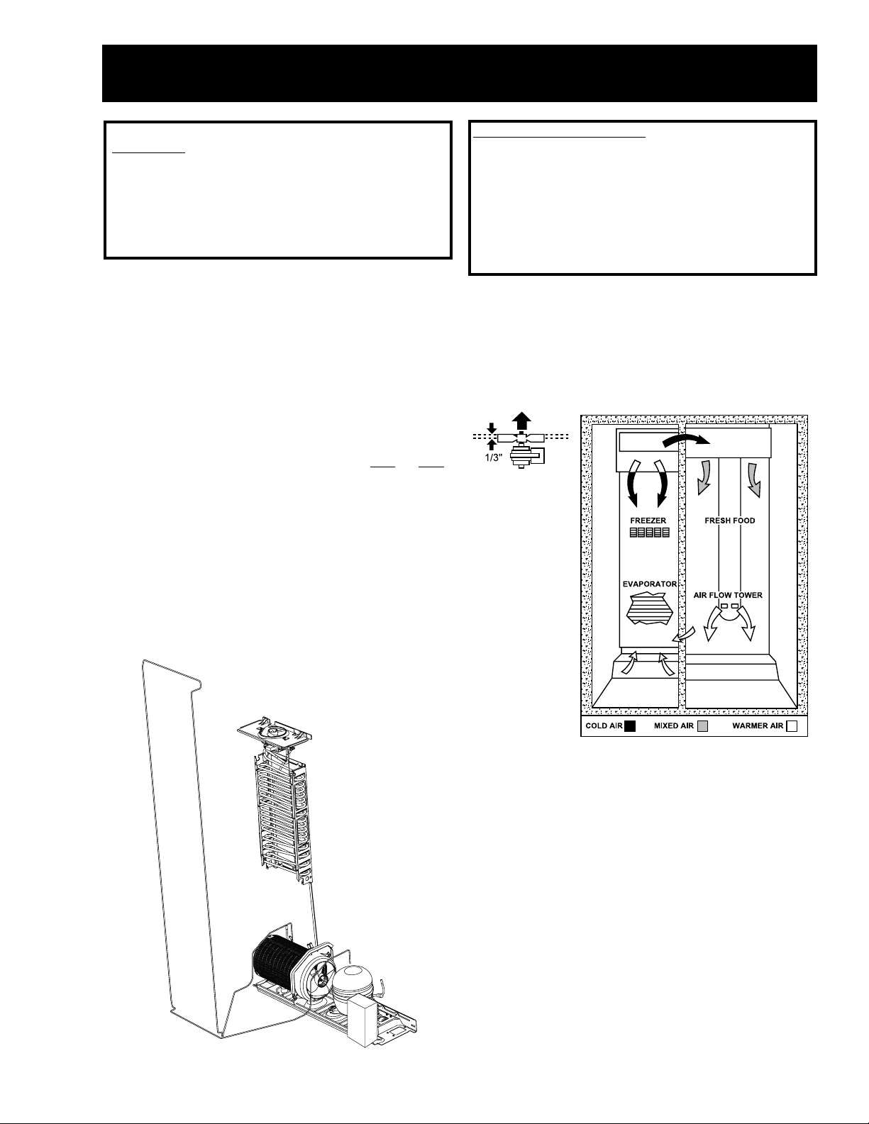
AIR FLOW
– 3 –
Page 6
Nomenclature
P S H 23 S G N A F BS
Brand/Product
G - GE
H - Hotpoint
P - Profile
E - Eterna
S - GE Select
Configuration
S - Side by Side
T - Top Mount
Depth/Power
H - Inverter Compressor
S - Standard Depth
T - Tropical
G - Global
Capacity
(cubic feet) AHAM Rated Volume
Interior Features/Shelves
A - Leader Wire
D - Deluxe Wire
I - Deluxe Glass
K - Spillproof/Slideout Glass F - 6 Month filter
S - Stainless S teel Doors
Q - Showcase Derivative
U - A VB Derivative
W - HPS Derivative
X - Regional Derivative
Exterior Color
BS - Black on Stainless
WW - White on White
AA - Almond on Almond
BB - Black on Black
CC - Bisque on Bisque
WH - White on Black
Door T ype
F - Flat
R - Right
L - Left Door Swing
Engineering
A - Initial Design
B - 1st Revision
Model Year
N - 2002
Icemaker/Exterior
B - Non Dispenser
IM Ready
D - Cubed Ice/Water
E - Cubed/Crushed/Water
F - 6-Month Filter
Cubed/Crushed
G - 1-Y ear Filter
Cubed/Crushed
I - In-line Filter/Indicator
Cubed/Crushed/Water
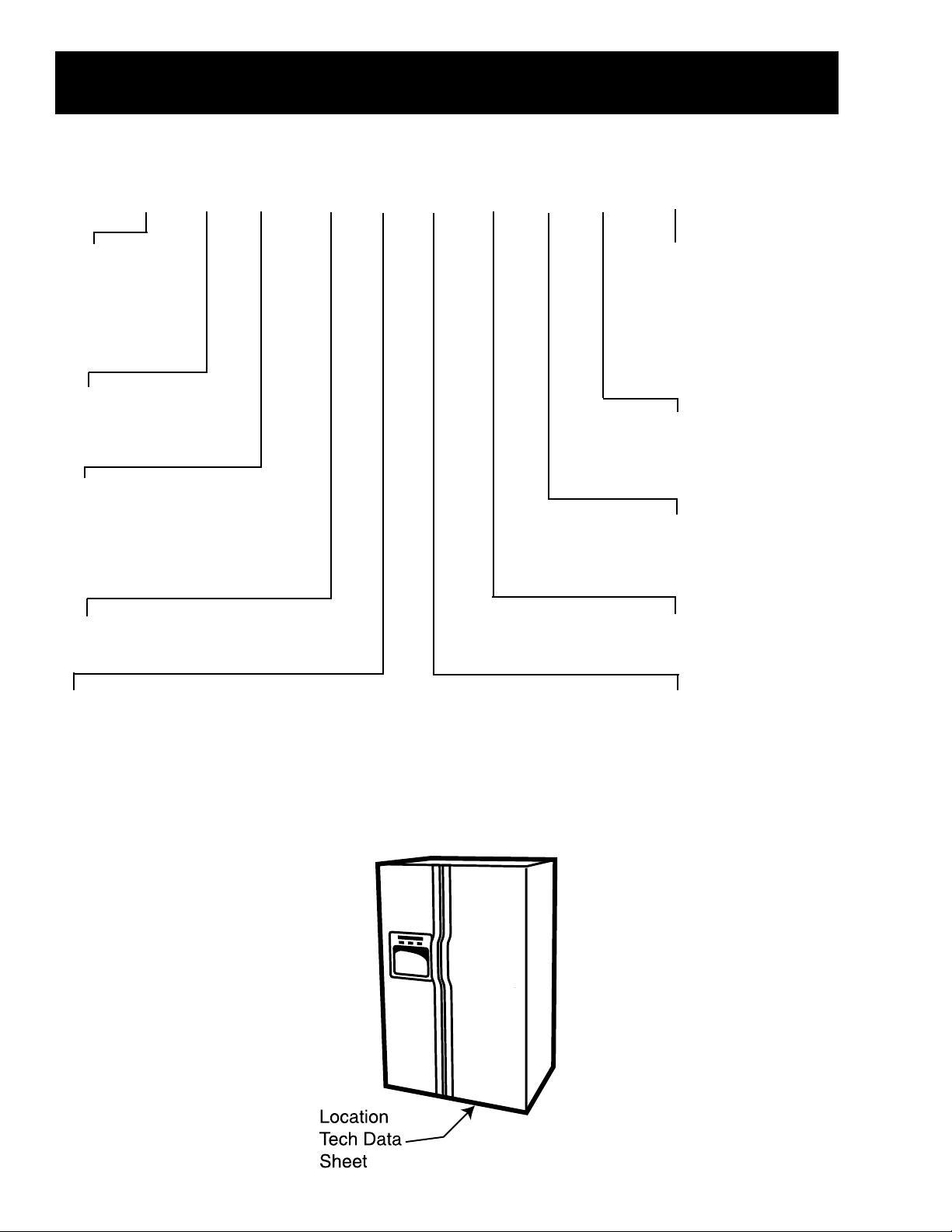
The rating plate, located on the upper left
wall of the fresh food compartment,
contains the model and serial numbers.
Additionally , the rating plate specifies the
minimum installation clearances,
electrical voltage, frequency, maximum
amperage rating, and refrigerant charge,
and type.
– 4 –
Page 7
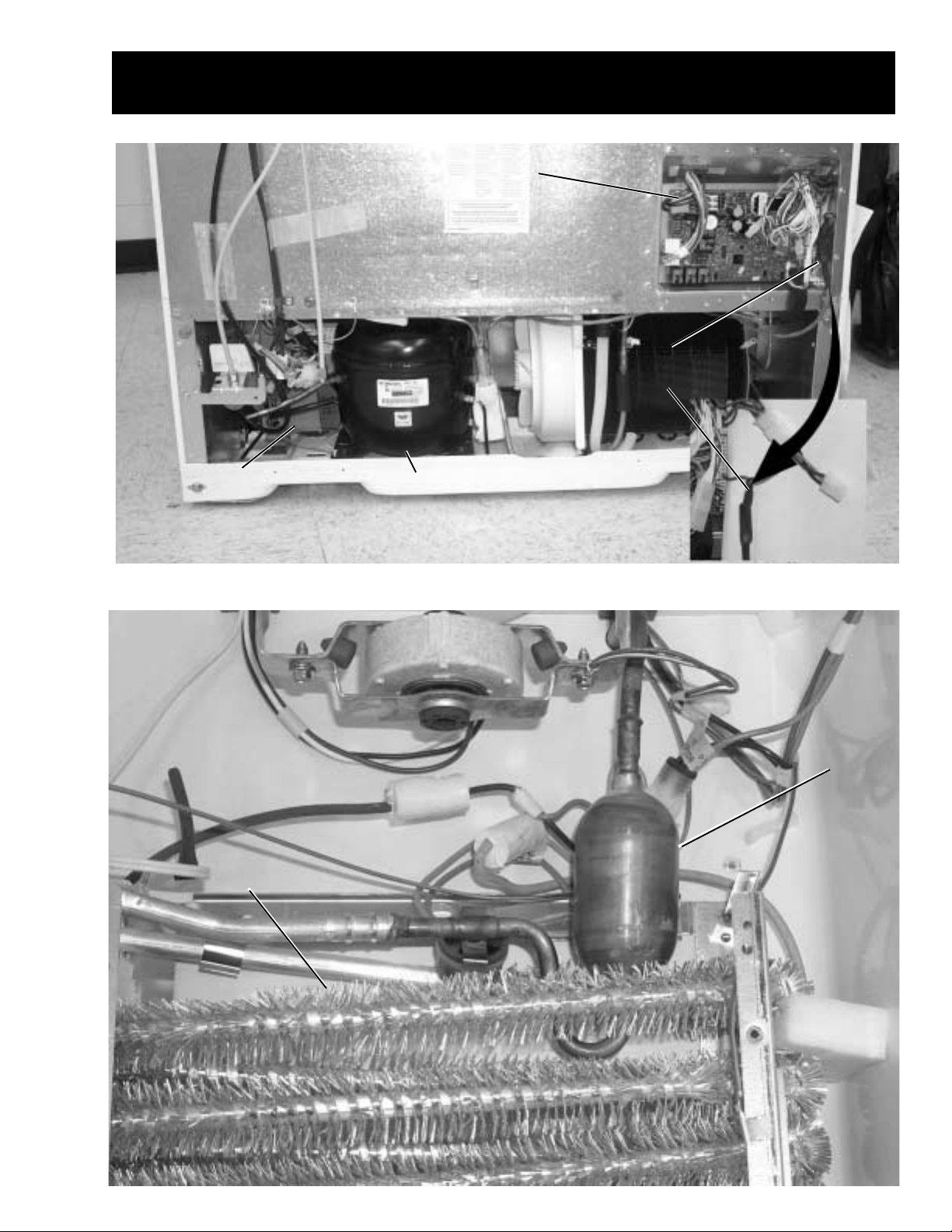
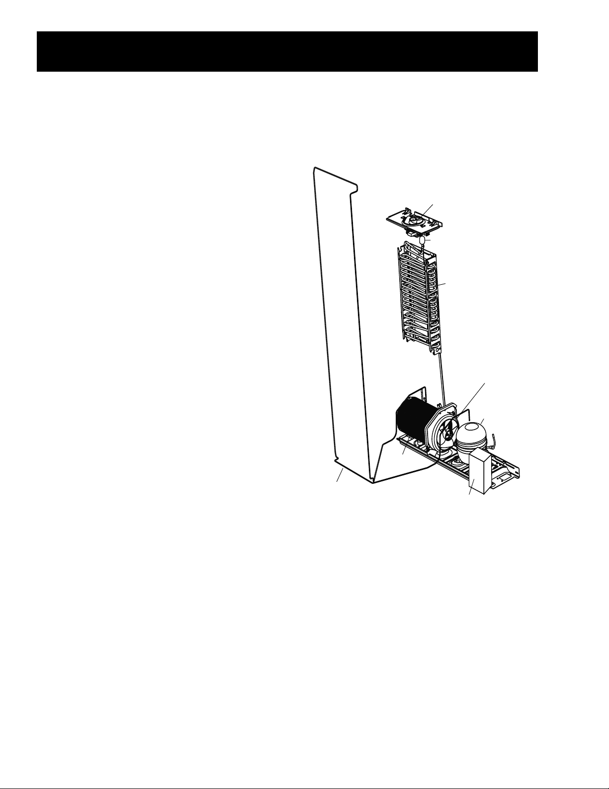
Inverter
Inverter
Component Locator Views
Main Control Board
Main Control Board
Current-Source
Current-Source
Circuit Board
Circuit Board
Inverter CompressorInverter Compressor
Evaporator
Evaporator
– 5 –
Accumulator
Accumulator
Page 8

Principals of Refrigeration
Phases of Refrigeration
The compressor is the heart of any refrigeration system. It serves as a pump to circulate the refrigerant
and create pressure within the system. When the compressor is operating, one side of the system is at
high pressure and the other side is at low pressure. This difference in pressure creates a temperature
difference that allows heat to be removed from inside the cabinet and transferred to the outside of the
cabinet.
The 3 phases of the refrigeration system are:
• Compression
• Condensation – occurs on the “high side” of the system
••
• Evaporation – occurs on the “low side” of the system
••
Compression
While the compressor is operating, refrigerant vapor is discharged into the condenser. A capillary (small
diameter tube) is connected to the outlet of the condenser . The capillary tube restricts the amount of
refrigerant that leaves the condenser . As the compressor continues to pump refrigerant into the
condenser, this restriction causes pressure to build in the condenser. Typical operating pressure in the
condenser in the inverter compressor system is 85 to 90 psig in an ambient temperature of 75 °F.
Condensation
The compressed refrigerant vapor entering the condenser is warmer than the temperature of the room.
As the refrigerant travels though the condenser , the heat from the high-pressure vapor is transferred to
the condenser , which transfers heat to the surrounding air (by convection). As heat is removed from the
high-pressure vapor, it begins to condense into a high-pressure liquid. This high-pressure liquid
refrigerant flows to the end of the condenser and is forced into the capillary tube.
Evaporation
High-pressure liquid refrigerant travels through the capillary and exits at a very high rate of speed into the
much-larger tubing of the evaporator . Low pressure in the evaporator, caused by the suction of the
compressor (typically 0 to 5 psig in the inverter compressor) causes the liquid refrigerant to vaporize.
Approximately 30% of the refrigerant will vaporize immediately upon exiting the capillary . The remaining
refrigerant will vaporize as it travels through the evaporator . As the refrigerant vaporizes, it absorbs
heat. Heat inside the cabinet is transferred (by convection) to the evaporator because the evaporator
temperature is lower than the cabinet air temperature. Refrigerant exiting the evaporator should have
completely vaporized so that only vapor is returned to the compressor through the suction line.
However , under certain conditions some refrigerant may remain in liquid form as it exit s the evaporator.
The mixture of refrigerant (vapor and liquid) is known as “refrigerant quality .” Refrigerant that has a
higher ratio of vapor to liquid has a higher quality . Completely vaporized refrigerant has a quality rating of
100%. Refrigeration that is completely liquid has a quality rating of 0%. Refrigerant that is exiting the
evaporator should have a quality rating of 100%. Refrigerant that is exiting the condenser should have a
quality rating of 0%. Refrigerant quality is an important part of refrigeration system efficiency.
– 6 –
Page 9
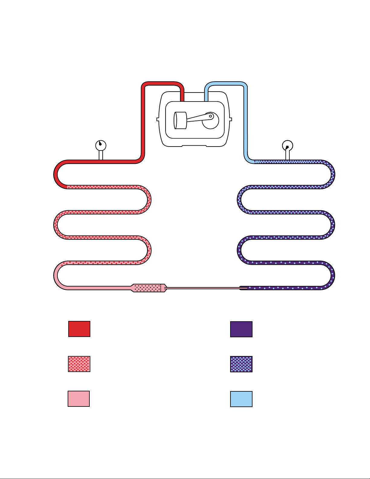
SINGLE-SPEED COMPRESSOR
70-135 PSIG
85-90 PSIG at
75 ˚F Ambient
CONDENSER
FILTER-DRYER
COMPRESSOR
CAPILLARY
0-5 PSIG
1-2 PSIG at
75 ˚F Ambient
EVAPORATOR
HIGH PRESSURE VAPOR
MIX OF LIQUID AND VAPOR
HIGH PRESSURE LIQUID
LOW PRESSURE LIQUID
MIX OF LIQUID AND VAPOR
LOW PRESSURE VAPOR
GEA01261
– 7 –
Page 10
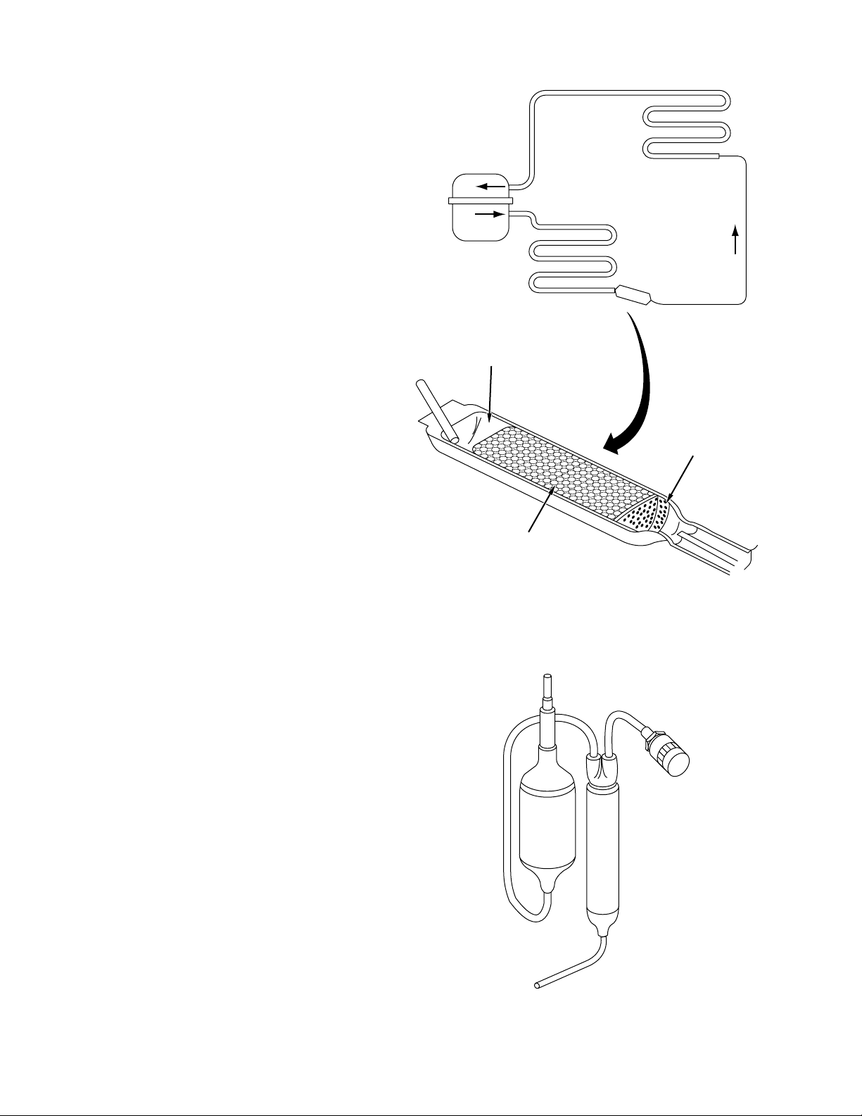
Dryer
The refrigeration system must be free from dirt
and moisture. A single particle of dirt, or one drop
of water, can cause the system to fail. For this
reason, a dryer is a necessary component of the
refrigeration system. The dryer consists of a
strainer at the inlet, a molecular sieve of beads,
and a screen at the outlet. The beads have the
ability to attract and absorb molecules of water but
reject the molecules of refrigerant, oil, nitrogen,
and most other substances. The strainer prevents
the beads from spilling into the inlet. The fine
mesh screen prevents particles (including crushed
beads) from plugging the capillary tube. The dryer
is normally located between the outlet of the
condenser and the inlet of the capillary .
SUCTION TUBE
EVAPORATOR
COMPRESSOR
DRYER
CONDENSER
CAPILLARY
SCREEN
STRAINER
Filter
A filter is provided in some refrigeration systems
and furnished with some replacement
compressors. The filter has the appearance of a
large diameter dryer. It has a very fine mesh
screen located at the outlet and a solid core, made
of a special porous material, that is capable of
chemically removing contaminants from the
system. An arrow, stamped on the body of the
filter, indicates the proper direction of flow.
A filter/dryer combination is furnished with
replacement compressors for systems using
R134a refrigerant. A new filter/dryer must be
installed any time an R134a system is repaired.
An additional 0.5 oz of refrigerant is required when
a filter/dryer is added to the high side of the
system.
MOLECULAR
SIEVE OF BEADS
GEA01257
– 8 –
GEA01258
Page 11
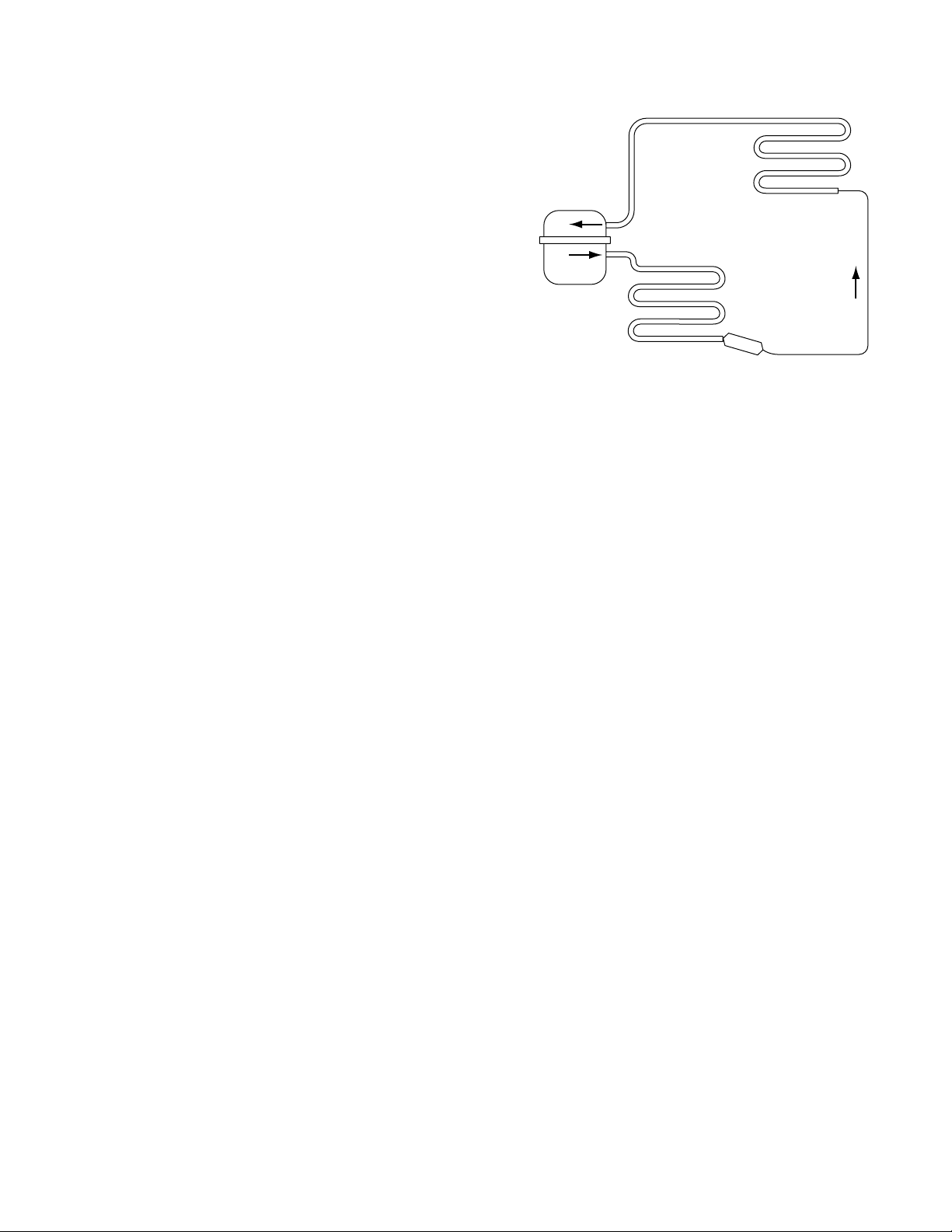
Capillary
GEA01256
CAPILLARY
CONDENSER
COMPRESSOR
SUCTION TUBE
EVAPORATOR
DRYER
The capillary is a very small diameter tube that is
about 6 to 8 feet long. Its primary function is to
control the flow of refrigerant into the evaporator .
The flow rate of a capillary is determined by its
diameter and is critical to the proper operation of
the refrigeration system. If a capillary is
shortened, the flow rate will increase. Likewise, if
it is lengthened the flow rate will decrease.
Therefore, when repairing a refrigeration system it
is very important to cut the capillary as close as
possible to the outlet of the dryer . The capillary is
not replaceable separately .
Heat Exchanger
The function of the heat exchanger is to transfer
heat from the warm liquid flowing through the
capillary to the cool vapor flowing through the
suction tube. The heat exchange occurs where
the capillary is soldered to the outside of the
suction tube. This arrangement improves the
efficiency of the system. By reducing the heat of
the capillary , the boiling point of the liquid entering
the evaporator is lowered. Increasing the heat of
the suction tube increases the density of the vapor
entering the compressor and also helps to prevent
the suction tube from sweating.
– 9 –
Page 12
Refrigeration System
The refrigeration system has several new components as well as several familiar ones. New
components include:
• Inverter compressor
• Inverter
• 3-speed condenser fan
• Accumulator at the outlet of the evaporator
Familiar components include:
• Condenser
• Condenser loop
• Dryer
• Evaporator
• Evaporator fan
The refrigeration system operates with optimum
efficiency and economy by changing the speed of
the compressor (and condenser fan) to meet
demand. During times of high usage, or in
extremely warm ambient conditions, the 3-speed,
inverter compressor will increase speed to meet
greater refrigeration requirements. When usage is
low, the compressor will operate at a slower
speed, reducing its energy requirement.
In the new system with the inverter compressor,
the flow of refrigerant through the components in
the system is the same as previous models with
the following exception: an accumulator has been
added to the outlet side of the evaporator.
EVAPORATOR FAN
ACCUMULATOR
EVAPORATOR
3-SPEED CONDENSER FAN
INVERTER
COMPRESSOR
CONDENSER
CONDENSER LOOP
INVERTER
– 10 –
GEA01262
Page 13
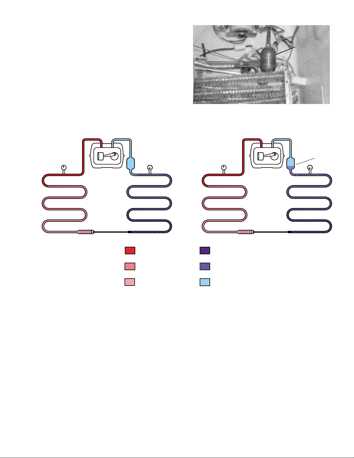
An accumulator has been installed at the outlet of
the evaporator to prevent liquid refrigerant (low
quality) from entering the suction line. Changes in
compressor speed (transition state) can
temporarily reduce refrigerant quality . The
accumulator compensates for this by collecting
and holding up to 2 oz of liquid while allowing
vapor to pass. Within minutes after the
compressor speed change, the system attains a
steady state (becomes stabilized), the liquid
refrigerant in the accumulator vaporizes, and
refrigerant quality returns to normal.
Accumulator
Steady State
INVERTER COMPRESSOR
70-135 PSIG
85-90 PSIG at
75 ˚F Ambient
CONDENSER EVAPORATOR
FILTER-DRYER
COMPRESSOR
CAPILLARY
ACCUMULATOR
HIGH PRESSURE LIQUID
0-5 PSIG
1-2 PSIG at
75 ˚F Ambient
HIGH PRESSURE VAPOR
MIX OF LIQUID AND VAPOR
Transition State
INVERTER COMPRESSOR
70-135 PSIG
85-90 PSIG at
75 ˚F Ambient
CONDENSER EVAPORATOR
FILTER-DRYER
LOW PRESSURE LIQUID
MIX OF LIQUID AND VAPOR
LOW PRESSURE VAPOR
COMPRESSOR
CAPILLARY
ACCUMULATOR
LIQUID ENTERS
THE ACCUMULATOR
0-5 PSIG
1-2 PSIG at
75 ˚F Ambient
GEA01263
System Pressure
The refrigeration system should maintain a consistent pressure regardless of compressor speed.
Pressure variations, due to changing compressor speed, are minimized by matching the condenser fan
speed and evaporator fan speed to the compressor speed. The condenser and evaporator fans will
always operate at the same speed (low, medium, or high) as the compressor.
Low side system pressure should be between 0 and 5 psig dependant on ambient temperature.
System pressures in an ambient temperature of 75 °F should be:
••
• High Side – 85 to 90 psig
••
••
• Low Side – 1 to 2 psig
••
Refrigerant Charge
The refrigerant used in the sealed system is R134a. Proper system charge is 6 oz; however, an
additional 0.5 oz is required when adding a filter/dryer . Proper system charge is critical to the operation
of this unit.
– 11 –
Page 14
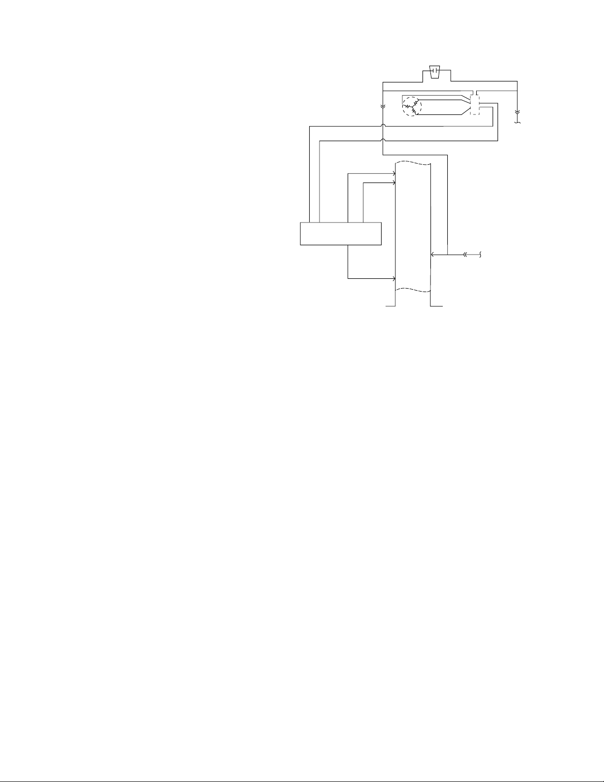
Inverter Compressor
The new inverter compressor is not controlled by
120 VAC output from the main control board, as in
previous models. The compressor is controlled by
the inverter.
Warning: Disconnecting the 6-pin connector
does not disconnect power (120 VAC) from the
inverter. The refrigerator must be unplugged
before servicing the inverter or compressor.
Caution: Do not attempt to direct-start the
compressor. The compressor operates on a
3-phase power supply . Applying 120 V AC to the
compressor will permanently damage the unit.
It is not possible to start the compressor
without an inverter.
The compressor is a reciprocating, variable speed,
4-pole type. It operates on 3-phase, 80 to 230 V AC
within a range of 57 to 104 Hz. Compressor speed
is controlled by voltage frequency and pulse width
modulation. Increasing frequency from the inverter
will produce an increase in compressor speed.
6-PIN
CONNECTOR
CURRENT-SOURCE
CIRCUIT BOARD
LOW VOLTA GE DC
CIRCUIT
CLASS 2
+12 VDC
CO
AC
INVERTER
ORANGE
ANGE
R
O
GE
N
A
R
O
BROWN
B
A
L
C
K
10Ω
Ω
0
1
COMPRESSOR
LUE
B
PURPLE
2
J4-
ON
M
M
J4-3
K
B
A
L
C
B
L
E
U
10Ω
BROWN
TAB 4
N
W
BRO
MAIN CONTROL BOARD
10
J3-
S
LINE VOLTAGE
GEA01260
• Frequency of 57 Hz will produce low speed operation at 1710 rpm.
• Frequency of 70 Hz will produce medium speed at 2100 rpm.
• Frequency of 104 Hz will produce 3120 rpm.
Note: Certain voltmeters will not be able to read voltage output or frequency from the inverter.
Compressor wattages at various speeds are:
• LOW - 65 watts
• MED - 100 watts
• HIGH - 150 watts
BTU rating also varies according to operating speed.
Compressor speed is based on the temperature setpoint in conjunction with the cabinet temperature.
Speeds are selected according to the following cabinet temperatures:
• 8 °F to 19.5 °F above setpoint = high speed
• 3.5 °F to 7.5 °F above setpoint = medium speed
• 1 °F to 3 °F above setpoint = low speed
Note: The compressor will run at medium speed if the cabinet temperature is 20 °F or more above the
setpoint.
The use of 3-phase power eliminates the need for the PTCR relay , cap acitor, and individual start and run
windings; therefore the start, run, and common pins found on conventional compressors are not
applicable on this 3-phase model. Compressor pin functions are identical and compressor lead wire
configuration is of no importance. A resistance of 9 to 1 1Ω should be read between any 2 of the 3 pins.
Should an open occur in the compressor winding or should one of the compressor lead wires become
open or disconnected, the inverter will stop voltage output to the compressor .
– 12 –
Page 15

High compressor torque enables the compressor to start against high pressure in the sealed system.
When power has been disconnected from an operating unit, the high torque will enable the compressor
to start immediately upon power restoration.
Compressor and sealed system operation is extremely smooth and cool. The compressor exterior may
be room temperature while operating; therefore a running unit may be difficult to detect.
To verify that the compressor is running:
Disconnect power from the unit and place a hand on the compressor. Reconnect power and feel for a
vibration when the compressor tries to start. It may take up to 8 seconds before the compressor
attempts to start.
To determine motor rpm:
Measure the frequency of the voltage being applied to the compressor and multiply this number by 30.
For example, a frequency measurement of 70 Hz would show a compressor speed of 2100 rpm (30 x
70 = 2100).
Note: If the compressor fails to start, the inverter will briefly stop voltage output. The inverter will make
12 consecutive attempts to start the compressor (once every 12 seconds). If, after 12 attempts, the
compressor has not started, an 8-minute count will occur. After 8 minutes, the inverter will attempt to
start the compressor again. If the compressor starts, normal operation will resume. If the compressor
fails to start, the process will be repeated.
Removing power from the unit will reset the
inverter count. When power is restored, the
inverter will attempt to start the compressor within
8 seconds.
Note:
• When ordering a replacement compressor,
6-PIN
CONNECTOR
BLU
PURPLE
E
BROWN
B
L
A
COMPRESSOR
AC
INVERTER
ORANGE
ORANGE
GE
N
A
R
O
C
K
10Ω
B
A
L
C
K
B
L
E
10Ω
U
10Ω
BROWN
order both the compressor and inverter.
Replace the compressor first. If, after
compressor installation, the compressor fails
to start, replace the inverter.
+12 VDC
CO
2
J4-
ON
MM
J4-3
• When servicing the compressor, it is important
to dress the wiring to keep low voltage DC
wiring and 120 V AC wiring separate.
CURRENT-SOURCE
CIRCUIT BOARD
LOW VOLTA GE DC
CIRCUITS
CLASS 2
TAB 4
BROWN
MAIN CONTROL BOARD
10
J3-
LINE VOLTAGE
GEA01260
– 13 –
Page 16

Inverter
Warning: Disconnecting the 6-pin connector does not disconnect power (120 VAC) from the
inverter. The refrigerator must be unplugged before servicing the inverter.
Note: Certain voltmeters will not be able to read voltage output from the inverter . If no voltage or erratic
voltage is measured, it does not necessarily indicate a faulty inverter.
The inverter receives 120 VAC line-in from the power supply. The inverter converts this single-phase,
60 Hz, 120 VAC into 3-phase, 230 V AC, with frequency variations between 57 Hz and 104 Hz. This
voltage is delivered to the compressor through 3 lead wires. Each wire will carry identical voltage and
frequency. When checking inverter voltage output, connect the test-meter leads to any 2 of the 3
compressor lead wires. The same reading should be measured between any 2 of the 3 wires.
Note: The compressor leads must be connected to measure voltage output. If the compressor wires
are not connected, or if an open occurs in one of the 3 lead wires or in the compressor , the inverter will
stop voltage output.
The inverter controls compressor speed by frequency variation and by pulse width modulation (PWM).
Changing frequency and PWM will cause an effective voltage between 80 and 230 VAC to be received at
the compressor.
• Low speed (1710 rpm) - 57 Hz
• Medium speed (2100 rpm) - 70 Hz
• High Speed (3120 rpm) - 104 Hz
The inverter receives commands from the main control board. The main control board will send a
(PWM) run signal between 1.5 and 3.5 VDC
effective voltage to the inverter. In the circuit
between the main control board and the inverter, a
current-source circuit board is used to amplify the
pulse width modulated voltage. The signal voltage
at the inverter should be higher than the signal
voltage sent by the main control board. The
inverter will select compressor speed (voltage
Current-Source
Current-Source
Circuit Board
Circuit Board
output) based on this signal. A signal voltage from
the main control board (J3-10 to J2-3) lower than
1.5 VDC or greater than 3.5 VDC indicates a faulty
main control board. The main control board will only send a run signal to the inverter when the
compressor should be on.
Note: When measuring signal voltage (from the main control board) at the inverter , disconnect the wire
harness connector at the inverter and measure the voltage at the connector .
The inverter will monitor compressor operation and if the compressor fails to start or excessive current
draw (4 amps maximum) is detected, the inverter will briefly stop voltage output. The inverter will then
make 12 consecutive compressor start attempts (once every 12 seconds). If after 12 attempts the
compressor has not started, an 8-minute count will initiate. After the 8-minute count, the inverter will
attempt to start the compressor again. If the compressor starts, normal operation will resume. If the
compressor fails to start, this process will be repeated. Removing power to the unit will reset the
inverter count. When power is restored, the inverter will attempt to start the compressor within 8
seconds.
The inverter has a built-in circuit protection to guard against damage from a failed or shorted
compressor. However, if a failed compressor is diagnosed, order a new compressor and inverter. If the
compressor fails to start after replacement, replace the inverter.
– 14 –
Page 17

Note: When servicing the inverter, it is import ant
to dress the wiring to keep low-voltage DC wiring
and 120 V AC wiring separate.
To remove the inverter:
1. Unplug the unit.
2. Remove the rear access cover.
3. Remove the screw securing the water valve
and position to access the inverter .
4. Remove 1 screw (1/4 in) securing the inverter.
Slide the inverter forward to release the back
tab from the machine compartment bottom.
Note: It may be necessary to bend the process
tube in order to remove the inverter. If it is
necessary to bend the process tube, use extreme
care.
5. Turn the inverter horizontally and slide out of
the machine compartment.
Water Valve
To remove the inverter cover:
Use a small screwdriver to release the two small
tabs and carefully remove the inverter cover.
Inverter
Inverter
Line-In (L1)
Line-In (L1)
Inverter
Tabs
Signal Wire Connector
Signal Wire Connector
(From Main Control Board)
(From Main Control Board)
Compressor Lead
Compressor Lead
Wires
Wires
– 15 –
Page 18

Adaptive Defrost
Adaptive Defrost
Adaptive Defrost can be described as a defrost
system that adapts to a refrigerator’s surrounding
environment and household usage.
Unlike conventional defrost systems that use
electromechanical timers with a fixed defrost cycle
time, Adaptive Defrost utilizes an intelligent,
electronic control to determine when the defrost
cycle is necessary. In order to accomplish the
correct defrost cycle time, the main control board
monitors the following refrigerator operations:
• Length of time the refrigerator doors were open
since the last defrost cycle
• Length of time the compressor has run since
the last defrost cycle
• Amount of time the defrost heaters were on in
the last defrost cycle
Adaptive Defrost is divided into 5 separate cycles.
Those operations are:
• Cooling Operation
• Pre-Chill Operation
• Defrost Heater Operation
• Dwell Period
• Post Dwell
(See Pub. #31-9062 for more information on
Adaptive Defrost.)
Adaptive Defrost (Cooling Operation)
During the cooling operation, the main control
board monitors door opening (fresh food and
freezer doors) and compressor run times. The
length of time between consecutive defrosts is
reduced by each door opening. If the doors are not
opened, the compressor will run up to 60 hours
between defrosts. If the doors are opened
frequently and/or for long periods of time, the
compressor run time between defrosts will be
reduced to as little as 8 hours.
Adaptive Defrost (Pre-Chill Operation)
When the main control board determines that
defrost is necessary, it will force the refrigerator
into a continuous cool mode (pre-chill). During prechill, the freezer temperature may be driven below
the set point. However , the fresh food temperature
will be regulated by the damper . Pre-chill will
continue until one of the following 3 conditions
have been met.
• freezer temperature of -9 °F
• evaporator temperature of -25 °F
• 110 minutes of continuous run time with no
door openings
The average pre-chill is complete within 30 to
40 minutes. This model does not have a defrost
holdoff.
Adaptive Defrost (Defrost Heater Operation)
After pre-chill has concluded, the main control
board turns off the compressor, condenser fan,
and evaporator fan.
During defrost operation, the main control board
monitors the evaporator temperature using
evaporator thermistor inputs. Typically, the
evaporator thermistor will sense a temperature of
70 °F within 20 to 30 minutes. When the
thermistor senses 70 °F, the main control board
will terminate defrost heater operation. Maximum
defrost cycle (heater on) time is 40 minutes (main
control board time out).
The defrost system is protected by a defrost
termination thermostat (bimetal switch). The
thermostat opens when the evaporator
temperature raises to 140 °F and closes when the
evaporator temperature lowers to 110 °F.
– 16 –
Page 19

Adaptive Defrost (Dwell Period)
After defrost heater operation has been terminated
by the main control board, a 5-minute dwell period
occurs. During this period, the compressor,
condenser fan, and evaporator fan remain off. The
remaining frost melting from the evaporator will
continue to drip and drain so that, prior to the
cooling operation, the evaporator will be totally
clear of any moisture. After the 5-minute dwell
period, the unit goes into post dwell.
Abnormal Operating Characteristics
(Incorrect Operation)
• Rapid fan speed changes. Fan takes at least
1 minute to change speeds.
• Compressor running without the condenser
fan. The compressor and condenser fan
should always run at the same time.
Liner Protection Mode
Adaptive Defrost (Post Dwell)
The post dwell period is designed to cool the
evaporator before circulating air within the
refrigerator . This prevent s any residual heat on the
evaporator from being distributed in the freezer .
During this period, the compressor and the
condenser fan are on, but all interior fans are off
and the damper is closed. Post dwell will last 20
minutes or until the evaporator temperature
reaches 0 °F on this model.
Normal Operating Characteristics That Are
Different from Previous Models
• Compressor changes speed.
• Condenser fan changes speed.
• Fresh food fan changes speed.
• Compressor and fans can run continuously for
more than 8 hours.
The liner protection mode will activate if either of
the doors has been open for 3 minutes. This
mode will start the evaporator fan on high speed.
This mode is controlled by 2 timers. Timer #1
monitors door-open time. A 3-minute door-open
count begins when the door is opened. If
3 minutes elapse before the door is closed, the
liner protection mode will become active. Once
the door is closed, timer #1 resets and liner
protection mode goes into standby. In standby,
normal fan and damper operations resume and
timer #2 begins a 3-minute door-closed count.
If 3 minutes elapse without a door opening, liner
protection mode will completely deactivate. If a
door is opened within the timer #2 door-closed
count, the remaining time in the door-closed count
will be deducted from the timer #1 door-open
count.
– 17 –
Page 20

Fans
Evaporator Fan
The position of the fan blade in relation to the shroud is important. Refer to illustration for specifications.
5/16" ± 0.03
1.0" ± 0.05 Target
Blade tip
Orifice
Air Flow
Motor
GEA01149
The evaporator fan is the same fan used on previous models; however a significant difference is that the
main control board does not require, nor receive, input from the fan feedback/rpm (blue) wire. The fan
utilizes a permanent magnet, 4-pole, DC motor that operates at three different speeds: high, medium,
and low . The speed of the fan is controlled by the voltage output from the main control board. V o ltage
output from the control board to the fan is 13.2 VDC; however to regulate the speed of the fan, the main
control board uses pulse width modulation (PWM). When operating, voltage is sent in pulses (much like
a duty cycle) as opposed to an uninterrupted flow. This pulsing of 13.2 VDC produces ef fective volt age
being received at the motor, which is the equivalent to a reduction in volt age. Fan speed will be selected
and maintained by the main control board regulating the length and frequency of the 13.2 VDC pulse.
One complete revolution of the motor is comprised of all 4 poles. To determine the rpm of the fan, do
the following: Measure the frequency being applied to the motor. Multiply this number by 15 (60 seconds
divided by 4 poles). For example, a frequency measurement of 200 Hz multiplied by 15 would show a
fan speed of 3000 rpm (15 x 200 = 3000). Temperature may cause some fan speed variation. Fan
speed may vary +/- 5%, depending on the temperature, with higher temperatures causing slightly higher
speeds.
9.5 VDC
8 VDC
6.5 VDC
12 VDC
0 VDC
High Speed (9.5 VDC measured)
12 VDC
0 VDC
Medium Speed (8 VDC measured)
12 VDC
0 VDC
Low Speed (6.5 VDC measured)
– 18 –
Page 21

The evaporator fan has a 4-wire connection:
White Wire (DC Common)
The white wire is the DC common wire used for
testing. During repairs, DC polarity must be
observed. Reversing the DC polarity will cause a
shorted motor and/or board.
Red Wire (Supply)
Each motor uses an internal electronic controller
to operate the motor. Supply volt age from the
main control board remains at a constant 12 VDC.
Blue Wire (Feedback/RPM)
On previous Arctica models, the blue wire
reported rpm (speed) information to the main
control board for speed control purposes. On this
model, the board does not require nor read any
feedback information from the fan motor.
Yellow Wire (Signal)
The yellow wire is the input wire from the main
control board. The main control board provides
6.5 VDC effective voltage for low speed, 8 VDC
effective voltage for medium speed, and 9.5 VDC
for high speed. The fan will operate in low speed
only when the fresh food thermistor is satisfied.
Note: When testing these motors:
• You cannot test with an ohmmeter.
• DC common is not AC common.
• Verify 2 volt age potentials:
a. Red to white - power for internal controller
b. Yellow to white - power for fan
• Observe circuit polarity.
• Motors can be run for short periods using a
9-volt battery . Connect the white wire to the
negative (-) battery terminal only. Connect the
red and yellow wires to the positive (+) battery
terminal.
– 19 –
Page 22

Condenser Fan
The fan is mounted in the machine compartment
with the No-Clean condenser. The fan and fan
shroud are mounted on one end of the condenser,
and the other end of the condenser is blocked.
When the fan is operating, air is pulled from the
center of the condenser , drawing air in through the
coils. The air is then exhausted over the
compressor and out the right side of the
refrigerator.
Inlet air is available through the left front and left
rear of the machine compartment. A rubber divider
strip underneath the refrigerator divides the inlet
and outlet sides of the machine compartment.
Rear
Baffle
Front
GEA01152
The rear access cover must be tightly fitted to
prevent air from being exhausted directly out of the
rear of the machine compartment, bypassing the
compressor.
The condenser fan is mounted with screws to a
fan shroud and mounting bracket that is attached
to the condenser .
Refer to the illustration for fan blade adjustment.
The condenser fan is the same permanent-
magnet, 4-pole, DC motor used in previous Arctica
models; however a significant difference is that the
fan will operate at 3 speeds. Fan speed (low,
medium, high) corresponds with compressor
speed to minimize pressure variations in the
sealed system. The speed of the fan is controlled
by the voltage output from the main control board.
Voltage output from the control board to the fan is
13.2 VDC; however to regulate the speed of the
fan, the main control board uses pulse width
modulation (PWM). When operating, voltage is
sent in pulses (much like a duty cycle) as opposed
to an uninterrupted flow . This pulsing of 13.2 VDC
produces effective voltage being received at the
motor , which is the equivalent to a reduction in
voltage. Fan speed will be selected and
maintained by the main control board regulating the
length and frequency of the 13.2 VDC pulse.
1/2"
Housing
Fan
0.375"
Motor
Air Flow
Bracket
0.50" ± 0.05
GEA01148
– 20 –
Page 23

One complete revolution of the motor is comprised of all 4 poles. To determine the rpm of the fan, do
the following: Measure the frequency being applied to the motor. Multiply this number by 15 (60 seconds
divided by 4 poles). For example, a frequency measurement of 200 Hz multiplied by 15 would show a
fan speed of 3000 rpm (15 x 200 = 3000). Temperature may cause some fan speed variation. Fan
speed may vary +/- 5%, depending on the temperature, with higher temperatures causing slightly higher
speeds. Condenser fan speed is controlled by the same method (Pulse Width Modulation) used to
control evaporator fan speed. The condenser fan and evaporator fan will usually operate at the same
speed. No rpm/feedback wire is used for the condenser fan.
12 VDC
10.5 VDC
0 VDC
High Speed (10.5 VDC measured)
12 VDC
7.5 VDC
0 VDC
Medium Speed (7.5 VDC measured)
12 VDC
5.5 VDC
0 VDC
Low Speed (5.5 VDC measured)
Fresh Food Fan
A variable speed fresh food fan is located in the top of the fresh food section. When activated, the fresh
food fan will draw cool air from the freezer compartment into the fresh food compartment, providing
cooling independent of evaporator fan operation.
The main control board gathers information from the fresh food thermistors to determine when, and at
what speed, fan operation should occur . A constant 12 VDC is provided to the fan from the main control
board and switching occurs on the neutral side. S peed is regulated by Pulse Width Modulation on the
common side of the fan. When operating, the common side of the circuit is pulsed open and closed.
This pulsing produces effective voltage being received at the motor, which is the equivalent to a
reduction in voltage. Fan speed will be selected and maintained by the main control board regulating the
length and frequency of the 12 VDC pulse.
12 VDC
12 VDC
0 VDC
High Speed (12 VDC measured)
12 VDC
10 VDC
0 VDC
Medium Speed (10 VDC measured)
9 VDC
12 VDC
0 VDC
Low Speed (9 VDC measured)
– 21 –
Page 24

The main control board is located at the back of the refrigerator, above the machine comp artment on the
right-hand side.
It controls all refrigerator operations except the fresh food lights, freezer lights, and icemaker .
– 22 –
GEA00859
Pin 1 J8
Pin 1 J9
Pin 1 J11
Pin 1 J12
Pin 9 J7
Pin 8
Pin 7
Pin 6
Pin 5
Pin 4
Pin 3
Pin 2
Pin 1
Compressor
Defrost Heater
Line
Monogram Drain Pan Heater
Neutral
NIC
FZ Door Switch
FF Door Switch
QuickChill Heater
Auger Motor Interlock
Water Valve
Crusher Solenoid
Auger Motor
Pin 1
Pin 2
QuickChill Htr.
QuickChill Htr.
Evaporator Fan Tach.
Personality Input 5
Fan Common
Evaporator Fan
Condenser Fan
FF Fan
QuickChill Fan
Fan +12V
Low V oltage DC
120 V AC
J2 Pin 1
QuickChill Damper1 +
QuickChill Damper1 QuickChill Damper2 +
QuickChill Damper2 +5V
QuickChill Thermistor
Pin 2
Pin 3
Pin 4
Pin 5
Pin 6
Pin 7
Pin 8
J5 Pin 1
Pin 2
Pin 3
Pin 4
Pin 5
Pin 6
Comm. Tx/Rx
Comm. +12V
Comm. Common
Discrete Disp. Input 1
Discrete Disp. Input 2
Damper - Blue
Damper - White
Damper - Red
Damper - Yellow
FF Encoder Select
FZ Encoder Select
Encoder Signal
Encoder Signal
Encoder Signal
Encoder Signal
FF1 Thermistor
FF2 Thermistor
FZ Thermistor
Evaporator Thermistor
+5V
Personality Input 1
Personality Input 2
Personality Input 3
Personality Input 4
J4 Pin 1
Pin 2
Pin 3
Pin 4
Pin 5
Main Control Board
J3 Pin 1
Pin 2
Pin 3
Pin 4
Pin 5
Pin 6
Pin 7
Pin 8
Pin 9
Pin 10
J1 Pin 1
Pin 2
Pin 3
Pin 4
Pin 5
Pin 6
Pin 7
Pin 8
Pin 9
Page 25

ROTCENNOC NIP TUPNI TUPTUO NOITCNUF
1J1CDV
1J2CDV
1J3CDV
1J4CDV
1J5 CDV .1JnosnipytilanosrepdnasrotsimrehtrofCDV5sedivorP
SNOITINIFEDNIPDRAOBLORTNOC
,sporderutarepmetnehw,CTNsirotsimrehT.eulavrotsimrehtdoofhserffokcabdeeF
elcycotdesusieulavsihT.noitcuderegatlovnrutergnisuac,sesaercnieulavecnatsiser
sikcabdeeF.nafrosnednocdna,rosserpmoc,nafrotaropave,)desunehw(nafdoofhserf
.etunimrepegnahcfoseerged8otdnopserotderetlif
nehw,CTNsirotsimrehT.)desunehw(eulavrotsimrehtdoofhserfdnocesfokcabdeeF
eulavsihT.noitcuderegatlovnrutergnisuac,sesaercnieulavecnatsiser,sporderutarepmet
rosnednocdna,rosserpmoc,nafrotaropave,)desunehw(nafdoofhserfelcycotdesusi
.etunimrepegnahcfoseerged8otdnopserotderetlifsikcabdeeF.naf
,sporderutarepmetnehw,CTNsirotsimrehT.eulavrotsimrehtrezeerffokcabdeeF
elcycotdesusieulavsihT.noitcuderegatlovnrutergnisuac,sesaercnieulavecnatsiser
nehw(nafdoofhserfelcyctonlliwdna,nafrosnednocdna,rosserpmoc,nafrotaropave
.etunimrepegnahcfoseerged8otdnopserotderetlifsikcabdeeF.)desu
,sporderutarepmetnehw,CTNsirotsimrehT.eulavrotsimrehtrotaropavefokcabdeeF
desusieulavrotsimrehtsihT.noitcuderegatlovnrutergnisuac,sesaercnieulavecnatsiser
nehwffodnaeulavtsorfedwolebsierutarepmetnehwtsorfedgnirudnoretaehehtelcycot
otpu-rewopgniruddaeroslasieulavsihT.eulavtsorfedevobasierutarepmeteht
sikcabdeeF.noitaunitnocelcycroedomnwodllupotniseogrotaregirferfienimreted
.yletaidemmisdnopser,deretlifnu
1J6CDV
1J8CDV
1J9CDV
ROTCENNOC NIP TUPNI TUPTUO NOITCNUF
2J1zH .noitacilppasihtrofdaertonsikcabdeefnafrotaropavE.nafrotaropavemorfkcabdeeF
2J2 CDV.nipnoitcelesledoM
2J3 CDV .dnuorgCDV-nommocnafresnednocdnanafrotaropavE
2J4 CDV .MWPybdenimretedsiegatlovevitceffE.noitareporotomrofnafrotaropaveottuptuO
2J5 CDV .MWPybdenimretedsiegatlovevitceffE.noitareporotomrofnafrosnednocottuptuO
2J6 CDV
senimreted,snipytilanosreprehtohtiwnoitanibmocnidetcennocnehw,tahtnipnoitceleS
.ylnopu-rewopnonoitanibmocsdaeR.desugnimmargorpdnaledom
senimreted,snipytilanosreprehtohtiwnoitanibmocnidetcennocnehw,tahtnipnoitceleS
.ylnopu-rewopnonoitanibmocsdaeR.desugnimmargorpdnaledom
senimreted,snipytilanosreprehtohtiwnoitanibmocnidetcennocnehw,tahtnipnoitceleS
.ylnopu-rewopnonoitanibmocsdaeR.desugnimmargorpdnaledom
SNOITINIFEDNIPDRAOBLORTNOC
.lortnocdeepsnafMWProfdehctiwS.noitareporotomrofnafdoofhserfotnommoC
.MWPybdenimretedsiegatlovevitceffE
2J7 CDV .naf)looCmotsuC(llihCkciuQotmommocdehctiwS
2J8 CDV .egatlovtnatsnoc,snafllaotegatlovylppusCDV-21sedivorP
– 23 –
Page 26

ROTCENNOC NIP TUPNI TUPTUO NOITCNUF
3J1 CDV.rotomreppetsrepmaD
3J2 CDV.rotomreppetsrepmaD
3J3 CDV.rotomreppetsrepmaD
3J4 CDV.rotomreppetsrepmaD
SNOITINIFEDNIPDRAOBLORTNOC
3J01CDV
SNOITINIFEDNIPDRAOBLORTNOC
ROTCENNOC NIP TUPNI TUPTUO NOITCNUF
4J1
4J2 CDV.ylppusCDV21
4J3 CDV.nommocCD
ROTCENNOC NIP TUPNI TUPTUO NOITCNUF
latigiD
noitacinummoC
latigiD
noitacinummoC
SNOITINIFEDNIPDRAOBLORTNOC
deepsrosserpmoc,sesaercniegatlovsA.lortnocdeepsrosserpmocrofretrevnI
.sesaerced
rooddnadraoblortnocniamneewtebnoitacinummoclatigidyaw-2
llihCkciuQdna,)draob(lortnocerutarepmet,draobyalpsidresnepsid
.)draob(lortnocerutarepmet)looCmotsuC(
5J1 .repmad)looCmotsuC(llihCkciuQ
5J2 .repmad)looCmotsuC(llihCkciuQ
5J3 .repmad)looCmotsuC(llihCkciuQ
5J4 .repmad)looCmotsuC(llihCkciuQ
5J5 CDV .rotsimreht)looCmotsuC(llihCkciuQrofCDV5sedivorP
5J6CDV
– 24 –
erutarepmetnehw,CTNsirotsimrehT.rotsimreht)looCmotsuC(llihCkciuQfokcabdeeF
.egatlovnruterninoitcuderagnisuac,sesaercnieulavecnatsiser,spord
Page 27

ROTCENNOC NIP TUPNI TUPTUO NOITCNUF
7J1 CAV .CAV021-rotomreguaehtotegatlov1LdehctiwS
7J2 CAV .CAV021-dionelosrehsurcehtotegatlov1LdehctiwS
7J3 CAV .CAV021-evlavretawehtotegatlov1LdehctiwS
7J4CAV .desolcsiroodrezeerfnehwhctiwsroodrezeerfmorftupni1LsevieceR
7J5 CAV .CAV021-retaeh)looCmotsuC(lllihCkciuQehtotegatlov1LdehctiwS
7J6CAV
7J7CAV
7J9CAV.nilartuenCA
SNOITINIFEDNIPDRAOBLORTNOC
rofdesusitupnisihT.neposiroodnehwhctiwsrooddoofhserfmorftupni1LsevieceR
dna,snoitaluclacmralarood,snoitaluclacedomnoitcetorprenil,lortnocnafrotaropave
.snoitaluclactsorfedevitpada
rofdesusitupnisihT.neposiroodnehwhctiwsroodrezeerfmorftupni1LsevieceR
,snoitaluclactsorfedevitpada,snoitaluclacedomnoitcetorprenil,lortnocnafrotaropave
nidesolcebtsumhctiwS.snoitcnufkcolretniroodemosdna,snoitaluclacmralarood
ottengamroodtcuddnathgilresnepsidrof)desserpedhctiws(noitisopdesolcrood
.ezigrene
ROTCENNOC NIP TUPNI TUPTUO NOITCNUF
)2baT(9J1 CAV
ROTCENNOC NIP TUPNI TUPTUO NOITCNUF
)4baT(11J1CAV
SNOITINIFEDNIPDRAOBLORTNOC
tiucricsihtgnolwohstnuocremitA.CAV021-tiucrictsorfedehtotegatlov1LdehctiwS
evitpadasielcyctsorfedtxenehtfienimretedotnoitamrofnisihtsesudnadezigrenesi
.evitpadanonro
SNOITINIFEDNIPDRAOBLORTNOC
1LdehctiwsroflaitnetoptupniCAV021-stiucricdraoblortnocotegatlov1LtnatsnoC
.slanimret
– 25 –
Page 28

draoBlortnoCniaM
niP roloCeriW
1eulB
tnenopmoC
noitanimreT
nafrotaropavE
retemohcat
/tupnI
tuptuO
tupnI.ledomsihtotelbacilppatoN
2etihW/eulBledoMtupnICDV21=3nipot2nip2J
3revliS/etihWnommocnaFnommoCCDV21=3nipot8nip2J
)ediSCDegatloV-woL(rotcennoC2J
gnidaeRegatloVniP-ot-niP
4kcalB/wolleYnafrotaropavEtuptuO
5wolleYnafresnednoCtuptuO
6etihW/kcalBnafdoofhserFnommoC
7naTnaflooCmotsuCnommoCCDV21=8nipot7nip2J
8deR
120 VAC
GEA01195
Evaporator Fan Tach.
Personality Input 5
Fan Common
Evaporator Fan
Condenser Fan
FF Fan
QuickChill Fan
Fan +12V
Low Voltage DC
QuickChill Damper1 +
QuickChill Damper1 QuickChill Damper2 +
QuickChill Damper2 +5V
QuickChill Thermistor
J2 Pin 1
Pin 2
Pin 3
Pin 4
Pin 5
Pin 6
Pin 7
Pin 8
J5 Pin 1
Pin 2
Pin 3
Pin 4
Pin 5
Pin 6
egatlovylppusnaF
)CDV21(
Comm. Tx/Rx
Comm. +12V
Comm. Common
Discrete Disp. Input 1
Discrete Disp. Input 2
Damper - Blue
Damper - White
Damper - Red
Damper - Yellow
FF Encoder Select
FZ Encoder Select
Encoder Signal
Encoder Signal
Encoder Signal
Encoder Signal
FF1 Thermistor
FF2 Thermistor
FZ Thermistor
Evaporator Thermistor
+5V
Personality Input 1
Personality Input 2
Personality Input 3
Personality Input 4
J4 Pin 1
Pin 2
Pin 3
Pin 4
Pin 5
J3 Pin 1
Pin 2
Pin 3
Pin 4
Pin 5
Pin 6
Pin 7
Pin 8
Pin 9
Pin 10
J1 Pin 1
Pin 2
Pin 3
Pin 4
Pin 5
Pin 6
Pin 7
Pin 8
Pin 9
tuptuOCDV21=3nipot8nip2J
CDV5.9=3nipot4nip2J
,)dem(CDV8,)hgih(
)wol(CDV5.6
CDV5.01=3nipot5nip2J
,)dem(CDV5.7,)hgih(
)wol(CDV5.5
CDV21=6nipot8nip2J
CDV9,)dem(CDV01,)hgih(
)wol(
niP roloCeriW
1wolleYrotoMreppetSrepmaD
2kcalB/deRrotoMreppetSrepmaD
3nworB/etihWrotoMreppetSrepmaD
4wolleY/eulBrotoMreppetSrepmaD
01neerG/eulBretrevnItuptuO
tnenopmoC
noitanimreT
draoBlortnoCniaM
)ediSCDegatloV-woL(rotcennoC3J
/tupnI
tuptuO
gnidaeRegatloVniP-ot-niP
=3nip4Jot1nip3J
CDV3.1nahtssel-egatloVgnidnatS
CDV5.6.xorppa-egatloVgnilevarT
=3nip4Jot2nip3J
CDV3.1nahtssel-egatloVgnidnatS
CDV5.6.xorppa-egatloVgnilevarT
=3nip4Jot3nip3J
CDV3.1nahtssel-egatloVgnidnatS
CDV5.6.xorppa-egatloVgnilevarT
=3nip4Jot4nip3J
CDV3.1nahtssel-egatloVgnidnatS
CDV5.6.xorppa-egatloVgnilevarT
=3nip2Jot01nip3J
CDV5.3ot5.1
draoBlortnoCniaM
)ediSCDegatloV-woL(rotcennoC1J
niP roloCeriW
1deR/eulB
2wolleY
tnenopmoC
noitanimreT
doofhserF
1rotsimreht
doofhserF
2rotsimreht
/tupnI
tuptuO
tupnIA/N
tupnIA/N
3etihW/deRrotsimrehtrezeerFtupnIA/N
4etihW/eulB
5eulB
rotaropavE
rotsimreht
ylppusrotsimrehT
)CDV5(egatlov
tupnIA/N
tuptuOCDV5=3nip2Jot5nip1J
6eulBnipytilanosrePtupnICDV5=3nip2Jot6nip1J
8eulBnipytilanosrePtupnICDV5=3nip2Jot8nip1J
9eulBnipytilanosrePtupnICDV5=3nip2Jot9nip1J
– 26 –
gnidaeRegatloVniP-ot-niP
Page 29

draoBlortnoCniaM
)ediSCDegatloV-woL(rotcennoC4J
niP roloCeriW
1kcalB
2deR
3eulB
GEA01195
120 VA C
Evaporator Fan Tach.
Personality Input 5
Fan Common
Evaporator Fan
Condenser Fan
FF Fan
QuickChill Fan
Fan +12V
Low Voltage DC
QuickChill Damper1 +
QuickChill Damper1 QuickChill Damper2 +
QuickChill Damper2 +5V
QuickChill Thermistor
tnenopmoC
noitanimreT
erutarepmeT
lortnoc
erutarepmeT
lortnoc
erutarepmeT
lortnoc
Comm. Tx/Rx
Comm. +12V
Comm. Common
Discrete Disp. Input 1
Discrete Disp. Input 2
Damper - Blue
Damper - White
Damper - Red
Damper - Yellow
FF Encoder Select
J5 Pin 1
Pin 2
Pin 3
Pin 4
Pin 5
Pin 6
FZ Encoder Select
Encoder Signal
Encoder Signal
Encoder Signal
Encoder Signal
FF1 Thermistor
FF2 Thermistor
FZ Thermistor
Evaporator Thermistor
+5V
Personality Input 1
Personality Input 2
Personality Input 3
Personality Input 4
J2 Pin 1
Pin 2
Pin 3
Pin 4
Pin 5
Pin 6
Pin 7
Pin 8
tuptuO/tupnI
noitacinummoC
tuptuOCDV21=3nipot2nip4J
nommoCCDV21=3nipot2nip4J
J4 Pin 1
Pin 2
Pin 3
Pin 4
Pin 5
J3 Pin 1
Pin 2
Pin 3
Pin 4
Pin 5
Pin 6
Pin 7
Pin 8
Pin 9
Pin 10
J1 Pin 1
Pin 2
Pin 3
Pin 4
Pin 5
Pin 6
Pin 7
Pin 8
Pin 9
egatloVniP-ot-niP
gnidaeR
latigidyaw-2
.noitacinummoc
niP
1kniP
2wolleY
3nworB
4
5
6
draoBlortnoCniaM
)ediSCDegatloV-woL(rotcennoC5J
eriW
roloC
/wolleY
kcalB
tnenopmoC
noitanimreT
llihCkciuQ
)looCmotsuC(
repmaD
llihCkciuQ
)looCmotsuC(
repmaD
llihCkciuQ
)looCmotsuC(
repmaD
llihCkciuQ
)looCmotsuC(
repmaD
egatloVylppuS
)CDV5(
/tupnI
tuptuO
/tupnI
tuptuO
/tupnI
tuptuO
/tupnI
tuptuO
/tupnI
tuptuO
tuptuOCDV5=3nip2Jot01nip5J
gnidaeRegatloVniP-ot-niP
)ytiralopgnisrever(CDV21=2nipot1nip5J
)ytiralopgnisrever(CDV21=1nipot2nip5J
)ytiralopgnisrever(CDV21=4nipot3nip5J
)ytiralopgnisrever(CDV21=3nipot4nip5J
llihCkciuQ
)looCmotsuC(
tupnIA/N
rotsimrehT
– 27 –
Page 30

,11J,9JdraoBlortnoCniaM
)ediSegatloV-hgiH(srotcennoC
niP roloCeriW
9J
)2baT(
11J
)4baT(
tnenopmoC
noitanimreT
-ptuO/tupnI
tu
eulBretaeHtsorfeDtuptuOCAV021=9nip7Jot9J
nworBrekamecItupnICAV021=9nip7Jot11J
Pin 1 J8
Compressor
Pin 1 J9
Defrost Heater
Pin 1 J11
Line
Pin 1 J12
Monogram Drain Pan Heater
Pin 9 J7
Neutral
Pin 8
NIC
Pin 7
FZ Door Switch
Pin 6
FF Door Switch
Pin 5
QuickChill Heater
Pin 4
Auger Motor Interlock
Pin 3
Water Valve
Pin 2
Crusher Solenoid
Pin 1
Auger Motor
Pin 1
QuickChill Htr.
gnidaeRegatloVniPotniP
Pin 2
QuickChill Htr.
GEA01194
draoBlortnoCniaM
niP roloCeriW
tnenopmoC
noitanimreT
/tupnI
tuptuO
1 egieB reguA tuptuO CAV021=9nip7Jot1nip7J
2revliSdoineloSebuCtuptuOCAV021=9nip7Jot2nip7J
3wolleYevlaVretaWtuptuOCAV021=9nip7Jot3nip7J
4etihW/deRhctiwSrooDZFtupnI
5etihW/eulBllihCkciuQtuptuOCAV021=9nip7Jot5nip7J
6elpruP
7deR
thgilroodFF
hctiws
thgilroodrezeerF
hctiws
tupnI
tupnI
Low V oltage DC
120 VA C
)ediSCAV021(rotcennoC7J
gnidaeRegatloVniP-ot-niP
CAV021=9nip7Jot4nip7J
)desolcroodZF(
CAV021=9nip7Jot6nip7J
)neporoodFF(
CAV021=9nip7Jot7nip7J
)neporoodZF(
9egnarOlartueNlartueNlartueN
– 28 –
Page 31

Unplug refrigerator. Warm
freezer thermistor to 70 ˚F.
Connect power and set
temperature controls to
maximum settings.
Does compressor start?
YES
Adjust settings and
allow 24 hours to
stabilize.
Diagnostics
Compressor Not Running
Check condenser
fan for operation.
NO
Fan operating?
YES
Note: A signal voltage from the
main board to the inverter of less
than 1.5 VDC or greater than 3.5
VDC indicates a bad main board.
Verify signal voltage of 1.5 to
3.5 VDC at the main control
board connector J3-10 to J4-3.
Is voltage OK?
NO
NO
YES
Go to Condenser
Fan Not Running
flowchart.
Replace main
control board.
Verify freezer
thermisor is within
proper range using
thermistor values
chart. Is thermsitor
within proper range
NO
Check wiring
connections. If
wiring is OK, replace
thermsitor.
YES
Disconnect the main control
board signal wire at the inverter
and verify signal voltage.
Note: Voltage should be
higher at the inverter than at
the main board.
Voltage OK?
YES
Check compressor for
proper resistance.
9 to 11 should be
measured between all
pins.
Resistance OK?
YES
Check for 120 VAC
(L1) at inverter.
Voltage present?
YES
Replace wiring
harness from main
NO
NO
NO
control board to
inverter.
Replace compressor.
Note: When ordering a replacement
compressor, order the compressor and
inverter. Replace the compressor first.
If the compressor does not start
replace the inverter.
Repair inverter
wiring.
YES
Replace inverter.
Check compressor
lead wires and
connections.
Wires and
connections OK?
NO
Repair lead wire or
connection.
– 29 –
Page 32

Fresh Food Warm - Freezer Normal
Check control settings and temperatures.
Food at setting of 5 and 5 with no door
openings for 12 hours should be:
Fresh food 34 ˚F to 40 ˚F
Freezer -3 ˚F to +3 ˚F
Control settings OK
Control settings
require adjustment
Adjust settings and allow
24 hours to stabilize.
Basic refrigerator checks:
Door gasket seal OK?
Door switch - light turning off with door closed?
YES
Is evaporator fan running?
YES
Set temperature controls to 5 and 5. Unplug
Refrigerator.
Reconnect power.
Does damper door open immediately after
reconnecting power?
Yes
Is the airflow within the fresh food normal?
YES
NO
NO
NO
NO
Look for blockage at vents
Not Running flowchart.
or heavy frost on
evaporator cover.
Heavy frost
Repair as
necessary.
Go to Evaporator Fan
Go to Damper Not Operating
flowchart.
Blockage
Go to Heavy Frost on Evaporator
Remove blockage
from vent area.
flowchart.
Verify thermistors are within proper range
using the thermistor values chart.
Is the resistance within range?
YES
Check sealed system.
Does sealed system check OK?
Yes
Unit tests OK.
Run checks again.
Reset electronics by unplugging
refrigerator for 15 seconds.
Look for usage problem.
NO
NO
Check wiring connections.
If wiring is OK, replace
thermistor.
Repair
sealed system.
– 30 –
Page 33

Fresh Food Too Cold - Freezer Normal
Check control settings and temperatures.
Food at a setting of 5 and 5 with no door
openings for 12 hours should be:
Fresh food 34 ˚F to 40 ˚F
Freezer -3 ˚F to +3 ˚F
Control settings OK
Room temperature
must be above 55 ˚F
to avoid low ambient
condition.
Room temperature
above 55 ˚F?
YES
NO
Controls require
adjustment
Advise consumer of
refrigeration installation
requirements.
Adjust setting and allow
24 hours to stabilize.
Is the damper closed?
YES
Verify thermistors are
within proper range
using thermistor values
chart.
Is the resistance within
proper range?
YES
Unit tests OK.
Run checks again.
Reset electronics by
unplugging refrigerator for 15
seconds.
Look for usage problem.
NO
Go to Damper Not
Operating flowchart.
NO
Check wiring
connections. If
OK, replace
thermistor.
– 31 –
Page 34

Check control settings and
temperatures.
Food at setting of 5 and 5 with no door
openings for 12 hours should be:
Fresh food 34 ˚F to 40 ˚F
Freezer -3 ˚F to +3 ˚F
Control settings OK
Fresh Food Warm - Freezer W arm
Control setting
require adjustment
Adjust setting and allow
24 hours to stabilize.
Basic refrigerator checks:
Door gasket seal OK?
Door switch - light turning off with door closed?
YES
Is the condenser fan running?
YES
Is the evaporator fan running?
YES
Is the compressor running?
YES
Is the airflow within the freezer normal? NO
NO
NO
NO
NO
Repair as
necessary.
Condenser Fan Not Running flowchart.
Evaporator Fan Not Running flowchart.
Compressor Not Running flowchart.
Look for blockage
at vents or heavy
frost on evaporator
Go to
Go to
Go to
Blockage
cover.
Remove blockage
from evaporator cover
vent area.
YES
Verify thermistors are within proper range using
thermistor values chart.
Is the resistance within range?
YES
Check sealed system.
Does system check OK?
YES
Unit tests OK.
Run checks again.
Reset electronics by unplugging refrigerator
for 15 seconds.
Look for usage problem.
NO
NO
Check wiring
connections.
IF OK, replace
thermistor.
Repair
sealed system.
Heavy frost
Go to Heavy Frost on
Evaporator flowchart.
– 32 –
Page 35

Freezer Warm - Fresh Food Normal
Check control settings and temperatures.
Food at a setting of 5 and 5 with no
door openings for 12 hours should be:
Fresh food 34 ˚F to 40 ˚F.
Freezer -3 ˚F to +3 ˚F.
Control settings OK.
Control settings
require adjustment.
Adjust settings and allow
24 hours to stabilize.
Basic refrigerator checks:
Door switch - light turning off with drawer closed?
Door gasket seal OK?
YES
Is the evaporator fan running?
YES
Is the condenser fan running? NO
YES
Is the airflow within the
freezer normal?
YES
Verify thermistors are within proper
range using thermistor values chart.
Is the resistance within range?
NO Blockage
NO
NO
Look for blockage at vents
or heavy frost on
evaporator cover.
NO
Repair as
necessary.
Evaporator Fan Not Running flowchart.
Condenser Fan Not Running flowchart.
Heavy Frost
Check wiring
connections.
If OK, replace
thermistor.
Go to
Go to
Remove blockage
from vent area.
Go to Heavy Frost on Evaporator
flowchart.
YES
Check sealed system.
Does sealed system check OK?
YES
Unit tests OK.
Run checks again.
Reset electronics by unplugging
refrigerator for 15 seconds.
Look for usage problem.
NO
Repair
sealed system.
– 33 –
Page 36

Refrigerator Dead - No Sound, No Cooling
Are the interior lights on?
YES
Unplug J2 connector
from main control
board.
Check for 12 VDC at
main control board
pins J2-8 to J2-3.
Voltage present?
NO
NO
Check house supply voltage.
Check for 120 VAC at 3-pin
connector at the rear of the
Unplug J4 connector from
main control board.
Check for 12 VDC at
control board pins J4-2 to
Voltage present?
Is 120 VAC present?
YES
unit.
Is 120 VAC present?
YES
Repair wiring
connections at
3-pin connector.
J4-3.
NO
NO
NO
Replace main
control board.
House wiring
Problem.
Repair or replace
power cord.
YES
Short in fan motor circuit.
Go to Fan flowchart.
YES
Unplug the temperature
control harness.
Does the refrigerator
start once the harness is
unplugged.
YES
Replace temperature
control board.
NO
Verify thermistors are
within proper range
using the thermistor
values chart.
Is the resistance
within range?
YES
Replace main
control board.
NO
Check wiring
connections. If wiring
is OK, replace
thermistor.
– 34 –
Page 37

Damper Not Operating
Note: The damper will cycle open and closed every 1/2 hour.
Replace main
control board.
Remove blockage or
replace damper.
Verify thermistors are
within proper range
using thermistor
values chart.
Is the resistance
within range?
NO
Check wiring
connections. If
OK, replace
thermistor.
YES
Push on damper door to check manual
Push damper door halfway closed.
Unplug refrigerator to reset main control board.
Set temperature controls to 37 ˚F and 0 ˚F.
YESYES
immediately after reconnecting
(You have 10 seconds to check.)
Unplug harness connector at damper.
Measure resistance between the
blue and red wires and between the
Do you measure approximately 420 ohms for
movement.
Is the damper door stuck?
NO
Reconnect power.
Does damper door move
power?
NO
white and blue wires.
both readings?
Replace damper.NO
YES
Look for wiring
problem between
main control board
and damper. If
wiring is OK, replace
damper.
YES
Unplug J3 connector from main
control board. Unplug the refrigerator
to reset, then reconnect power.
Are there 6 VDC between pins J4-3
(common) and pins J3-1, J3-2, J3-3,
and J3-4?
Note: After reconnecting power, you
have 10 seconds to check.
NO
Replace main
control board.
– 35 –
Page 38

Always check door ajar,
customer usage -
numerous door
openings, etc.
Heavy Frost on Evaporator
Unplug refrigerator. Unplug connector J9
from the main control board. Measure
between blue wire on connector and
orange (neutral) wire on main control
board J7 pin 9.
Are there approximately 37 ohms?
NO
Check wiring harness,
defrost heater, and
defrost overtemperature
thermostat.
YES
Verify thermistors are within
proper range using
thermistor values chart.
Is resistance within range?
YES
Replace main
board.
NO
Check wiring
connections. If
OK, replace
thermistor.
– 36 –
Page 39

Always check fan for obstruction first.
Unplug refrigerator to reset
main control board.
Warm freezer thermistor to 70 ˚F.
Set temperature controls to 5 and 5.
Reconnect power.
Evaporator Fan Not Running
At the evaporator fan connector, check for
13 VDC from the red to white/silver wire
and 8 to 13 VDC from the
yellow/black to white/silver wire.
Is the voltage correct for both?
YES
Replace
evaporator fan
motor.
Unplug J2 connector on the main control board.
NO
Check for 13 VDC between pins J2-8 and J2-3
and 8 to 13 VDC between pins J2-4 and J2-3.
Is the voltage correct for both?
YES
Repair wiring between main control
board and evaporator fan motor.
NO
Replace main
control board.
– 37 –
Page 40

Always check for obstruction first.
Unplug refrigerator to reset
main control board.
Warm freezer thermistor to
70 ˚F and set temperature
controls to 5 and 5.
Reconnect power.
Condenser Fan Not Running
At the condenser fan connector,
check for 13 VDC from the red to
white/silver wire and 11 to 13 VDC
from the yellow to white/silver wire.
Is the voltage correct for both?
YES
Replace the condenser
fan motor.
NO
Unplug J2 connector on the main control
board. Check for 13 VDC between pins
J2-3 and J2-8 and 11 to 13 VDC between
pins J2-3 and J2-5.
Is the voltage correct for both?
YES
Repair wiring between
main control board and
condenser fan.
NO
Replace main
control board.
– 38 –
Page 41

Thermistors
This main control board uses input from 4 thermistors. These thermistors are located in the fresh food
section, the freezer section, and on the evaporator. The main control board monitors the thermistors to
determine the temperature in these areas of the unit and determines which components to run and
when to run them based on this information.
Thermistors can also be checked using diagnostic mode.
seulaVrotsimrehT
erutarepmeT
)C(seergeD
erutarepmeT
)F(seergeD
ecnatsiseR
smho-oliKni
03-22-k88 Ω
02-4-k4.84 Ω
01-41k6.72 Ω
023k3.61 Ω
0105k01 Ω
0286k2.6 Ω
0368k4 Ω
04401k6.2 Ω
NOTE: The thermistor’s resistance has a negative coefficient. As the temperature increases, the
thermistor’s resistance decreases.
– 39 –
Page 42

Schematic
3
1
2
– 40 –
Page 43

Wiring Diagram
Warning: Disconnecting the 6-pin
connector does not disconnect
power (120 V AC) from the
inverter. The refrigerator must
be unplugged before servicing
the inverter or compressor.
Caution: Do not attempt to
direct-start the compressor. The
compressor operates on a
3-phase power supply . Applying
120 V AC to the compressor will
permanently damage the unit. It
is not possible to start the
compressor without an inverter.
– 41 –
Page 44

Parts List
DESCRIPTION P ART NUMBER QUANTITY
ACCUMULATOR WR02X11264 1
COMPRESSOR WR87X10064 1
HARNESS INVERTER COMM WR23X10274 1
INVERTER ASM EMBRACE WR55X10155 1
BOARD ASM MAIN CTRL VSC WR55X10156 1
– 42 –
Page 45

W arranty
Sales slip or cancelled check is required as proof of original purchase date to obtain service
under warranty.
All warranty service is provided by our Factory Service Centers or an author ized Customer Care®
technician.
:fOdoirePehTroF :ecalpeRlliWEG
raeYenO
ehtfoetadehtmorF
esahcruplanigiro
sraeYeviF
ehtfoetadehtmorF
esahcruplanigiro
emitefiL
ehtfoetadehtmorF
esahcruplanigiro
syaDytrihT
foetadehtmorF
eht
esahcruplanigiro
trapynA sliafhcihw)egdirtracretlifretawgnidulcxe(rotaregirferehtfo
,ytnarraw ,edivorposlalliwEG ,egrahcfoeerf emoh-nidnaroballla
,edivorposlalliw ,egrahcfoeerf ecalperotecivresemoh-nidnaroballla
.trapevitcefedeht
.dedulcni
trapynA nitcefedaoteudsliafhcihwegdirtracretlifretawehtfo
,edivorposla ,egrahcfoeerf ehtecalperotecivresemoh-nidnaroballla
.trapevitcefed
:revoCtoNlliWEGtahW
• Service trips to your home to teach you
how to use the product.
• Improper installation.
• Failure of the product if it is abused or
used for other than the intended purpose
or used commercially.
• Loss of food due to spoilage.
• Replacement of house fuses or resetting of
circuit breakers.
sihtgniruD.pihsnamkrowroslairetamnitcefedaoteud raey-enolluf
.trapevitcefedehtecalperotecivres
metsysgnitaregirferdelaesehtfotrapynA ,rosserpmoceht(
aoteudsliafhcihw)gnibutgnitcennoclladna,rotaropave,resnednoc
sihtgniruD.pihsnamkrowroslairetamnitcefed ,ytnarrawraey-evif EG
rewardronaphguorht-eesynA napehtfirotaregirferehthtiwdehsinruf
tonerasrevocrewarD.esudlohesuohlamrongnirudskaerbrewardro
sihtgniruD.pihsnamkrowroslairetam ,ytnarrawyad-ytrihtlluf lliwew
• Replacement of the water filter cartridge
due to water pressure that is outside the
specified operating range or due to excessive sediment in the water supply.
• Replacement of water filter cartridge after
its expected useful life, 30 days.
• Damage to the product caused by accident,
fire, floods, or acts of God.
• Incidental or consequential damage caused
by possible defects with this appliance.
This warranty is extended to the original purchaser and any succeeding owner for products purchased
for home use within the USA. In Alaska, the warranty excludes the cost of shipping or service calls to
your home.
Some states do not allow the exclusion or limitation of incidental or consequential damages. This warranty gives you specific legal rights, and you may also have other rights which vary from state to state.
To know what your legal rights are, consult your local or state consumer affairs office or your state’s
Attorney General.
Warrantor: General Electric Company. Louisville, KY 40225
– 43 –
 Loading...