

Page 1
GE Consumer & Industrial
TECHNICAL SERVICE GUIDE
Arctica Side-by-Side
Dual Evaporator Refrigerators with
Electronic Touch Controls
MODEL SERIES:
PSH23PGR
PSH23PSR
PUB # 31-9118 10/04
Page 2

!
IMPORTANT SAFETY NOTICE
The information in this service guide is intended for use by
individuals possessing adequate backgrounds of electrical,
electronic, and mechanical experience. Any attempt to repair a
major ap pli ance may result in personal injury and property
damage. The man u fac tur er or seller cannot be responsible for the
in ter pre ta tion of this in for ma tion, nor can it assume any liability in
connection with its use.
WARNING
To avoid personal injury, disconnect power before servicing
this prod uct. If electrical power is required for diagnosis or test
purposes, disconnect the power immediately after performing the
necessary checks.
RECONNECT ALL GROUNDING DEVICES
If grounding wires, screws, straps, clips, nuts, or washers used to
complete a path to ground are removed for service, they must be
returned to their original position and properly fastened.
GE Consumer & Industrial
Technical Service Guide
Copyright © 2004
All rights reserved. This service guide may not be reproduced in whole or in part
in any form without written permission from the General Electric Company.
– 2
Page 3

Table of Contents
3-Way Valve .....................................................................................................................27
Accumulator .....................................................................................................................40
Check Valve .....................................................................................................................40
Components .....................................................................................................................18
Components Locator Views .............................................................................................11
Condenser Fan ................................................................................................................21
Control Board Connector Locator ....................................................................................12
Control Features ..............................................................................................................7
Defrost Cycles ..................................................................................................................22
Dispenser Light ................................................................................................................10
Dispenser Lock ................................................................................................................10
Dispensing Functions .......................................................................................................10
Evacuation and Charging Procedure ...............................................................................17
Freezer Evaporator ..........................................................................................................31
Freezer Evaporator Fan ...................................................................................................20
Freezer Section Cooling ..................................................................................................15
Fresh Food and Freezer Section Cooling ........................................................................16
Fresh Food Evaporator ....................................................................................................37
Fresh Food Evaporator Fan .............................................................................................19
Fresh Food Section Cooling ............................................................................................14
Illustrated Parts ................................................................................................................44
Introduction ......................................................................................................................4
Inverter .............................................................................................................................24
Inverter Compressor ........................................................................................................26
Liner Protection Mode ......................................................................................................10
Nomenclature ...................................................................................................................6
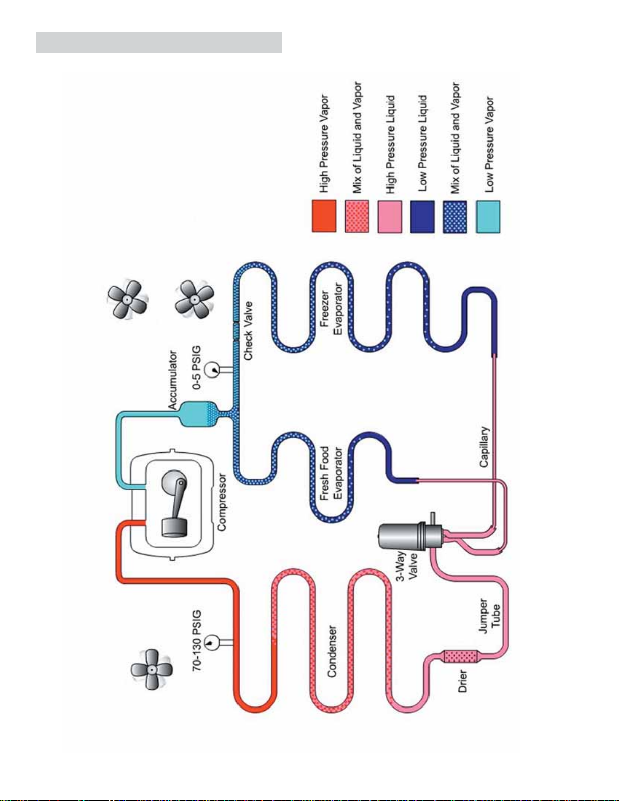
Refrigeration System .......................................................................................................14
Replacing Freezer Evaporator Using the Brazing Method ...............................................33
Replacing Freezer Evaporator Using the
Replacing Fresh Food Evaporator Using the Brazing Method .........................................38
Replacing Fresh Food Evaporator Using the
Replacing the 3-Way Valve ..............................................................................................29
LOKRING Method ............................................35
LOKRING Method ......................................39
Schematic ........................................................................................................................43
Technical Data .................................................................................................................5
Thermistors ......................................................................................................................18
Troubleshooting ...............................................................................................................41
Warranty ...........................................................................................................................62
– 3 –
Page 4
Introduction
This new Arctica dual evaporator refrigerator has the following features:
• Separate freezer and fresh food evaporators with independent cooling.
• No damper/air inlet assembly in the fresh food section creates more usuable space on the top shelf.
• Greater fresh food humidity to keep food
fresher, longer.
• 20% less freezer defrost for better food
preservation.
• 3-Way valve to direct refrigerant fl ow.
• Nearly silent, only 30 dBA.
The 3-speed compressor is controlled by
an inverter that receives input from the
low voltage DC side of the main control
board. The inverter always has 120 VAC
applied when the refrigerator is connected
to power. The main control board still makes
compressor decisions based on the input of
thermistors, door-open time, and input from
the temperature control panel. The main
control board also operates the condenser
fan, fresh food fan, freezer fan and adaptive
defrost.
The most signifi cant difference from previous
models is that the freezer and fresh food
evaporators are separate. The 3-way valve
directs refrigerant fl ow to each evaporator as needed. The fresh food section no longer relies on the
freezer evaporator for cooling. The evaporators are controlled separately by the main control board
through the 3-way valve.
– 4
Page 5
Technical Data
DISCONNECT POWER CORD BEFORE SERVICING
IMPORTANT - RECONNEC
T ALL GROUNDING DEVICE
S
All parts of this appliance capable of conducting
electrical current are grounded. If grounding wires,
screws, straps, clips, nuts or washers used to
complete a path to ground are removed for service,
they must be returned to their original position and
properly fastened.
ELECTRICAL SPECIFIC
Temperature Control (Position 5) ......................... 7-(-11 ) F
Defrost Control .......................................... 60hrs @ 45 min
Overtemperature Thermostat .............................. 140-110 F
Defrost Thermistor ........................................................ 75 F
Electrical Rating: 115V AC 60 Hz ......................... 11.6 Amp
Maximum Current Leakage ................................... 0.75 mA
Maximum Ground Path Resistance .................. 0.14 Ohms
ATIONS
w/ no door openings
NO LOAD PERFORMANCE
Control Position MID/MID
and Ambient of:
Fresh Food, F ................................................ 34-40 34-40
Frozen Food, F .............................................. (-3) 3 (-3) 3
Run Time, % ...................................................... <80 80-100
REFRIGER
Refrigerant Charge (R134a) ............................... 6.5 ounces
Compressor ....................................................833 BTU/hr @
Minimum Compressor Capacity ......................... 22 inches
Minimum Equalized Pressure
@ 70 F ....................................................................... 40 PSIG
@ 90 F ....................................................................... 54 PSIG
...............................................70 F 90 F
ATION SYSTEM
3000 RPM
IMPORTANT SAFE
TY NOTICE
This information is intended for use by individuals
possessing adequate backgrounds of electrical,
electronic and mechanical experience. Any attempt
to repair a major appliance may result in personal
injury and property damage. The manufacturer or
seller cannot be responsible for the interpretation of
this information, nor can it assume any liability in
connection with its use.
INSTALLATION
Minimum clearance required for air circulation:
TOP ............................................................................................. 1"
SIDES ................................................................................... 0.125"
REAR ........................................................................................ 0.5"
AIR FLOW
EVAPOR
ATO
R
– 5 –
Page 6
P S H 23 P G R A F BB
Brand/Product
G - GE
H - Hotpoint
P - Profi le
E - Eterna
S - GE Select
Confi guration
S - Side by Side
T - Top Mount
Nomenclature
Exterior Color
WW - White on White
BB - Black on Black
CC - Bisque on Bisque
SV - Stainless Visor
Door Type
F - Flat
R - Right
L - Left Door Swing
Depth/Power
H - Inverter Compressor
S - Standard Depth
T - Tropical
G - Global
Capacity
(cubic feet) AHAM Rated Volume
Interior Features/Shelves
A - Leader Wire
D - Deluxe Wire
F - 6 Month Filter
I - Deluxe Glass
K - Spillproof/Slideout Glass
P - Dual Evaporator
S - Stainless Steel Doors
Q - Showcase Derivative
U - AVB Derivative
W - HPS Derivative
X - Regional Derivative
The nomenclature plate is located on the
upper right wall of the fresh food compartment.
It contains the following information:
Nomenclature
Mini-Manual Location
• Model and Serial
Number
• Minimum
Installation
Clearances
• Electrical Voltage,
Frequency
• Maximum
Amperage Rating
• Refrigerant Charge
and Type
Engineering
A - Initial Design
B - 1st Revision
Model Year
R - 2004
Icemaker/Exterior
B - Non Dispenser
IM Ready
D - Cubed Ice/Water
E - Cubed/Crushed/
Water
F - 6-Month Filter
Cubed/Crushed
G - 1-Year Filter
Cubed/Crushed
I - In-line Filter/Indicator
Cubed/Crushed
Water
S - Stainless steel
Dispenser Trim
Serial Number
The fi rst two numbers of the serial number
identify the month and year of manufacture.
Example: AG123456S = January, 2004
A - JAN 2005 - H
D - FEB 2004 - G
F - MAR 2003 - F
G - APR 2002 - D
H - MAY 2001 - A
L - JUN 2000 - Z
M - JUL 1999 - V
R - AUG 1998 - T
S - SEP 1997 - S
T - OCT 1996 - R
V - NOV 1995 - M
Z - DEC 1994 - L
The letter des ig nat ing
the year re peats every
12 years.
Example:
T - 1974
T - 1986
T - 1998
– 6
Page 7
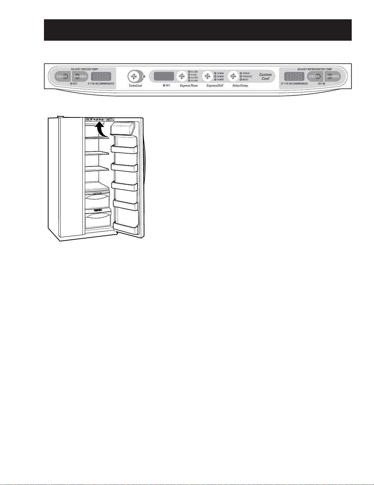
Control Features
• The temperature controls are preset in the factory at 37°F
for the refrigerator compartment and 0°F for the freezer
compartment.
• Allow 24 hours for the temperature to stabilize to the preset
recommended settings.
• The temperature controls can display both the SET
temperature as well as the actual temperature in the
refrigerator and freezer.
• The actual temperature may vary slightly from the SET
temperature based on usage and operating environment.
• Setting either or both controls to OFF stops cooling in both
the freezer and refrigerator compartments, but does not shut
off electrical power to the refrigerator.
• To change the temperature, press and release the WARMER or COLDER pad. The SET light will
come on and the display will show the set temperature.
• To change the temperature, tap either the WARMER or COLDER pad until the desired temperature
is displayed.
• Refrigerator temperatures can be adjusted between 34°F and 44°F and the freezer temperatures
can be adjusted between –6°F and +6°F.
• Once the desired temperature has been set, the temperature display will return to the actual
refrigerator and freezer temperatures after 5 seconds. Several adjustments may be required. Each
time you adjust controls, allow 24 hours for the refrigerator to reach the temperature you have set.
• To turn the cooling system off, tap the WARMER pad for either the refrigerator or the freezer until
the display shows OFF. To turn the unit back on, press the COLDER pad for either the refrigerator
or freezer. The SET light will illuminate on the side you selected. Then press the COLDER pad
again (on the side where the SET light is illuminated) and it will go to the preset points of 0°F for the
freezer and 37°F for the refrigerator.
• Setting either or both controls to OFF stops cooling in both the freezer and refrigerator
compartments, but does not shut off electrical power to the refrigerator.
– 7 –
Page 8
About CustomCool™.
How it Works
The CustomCool
dampers, a fan, a temperature thermistor
and a heater. Depending on the function
selected, a combination of these will be
used to quickly chill items, thaw items or
hold the pan at a specific temperature.
How to Use
ExpressThaw
ExpressChill
™
™
™
feature is a system of
Empty the pan. Place the Chill/Thaw
tray in the pan. Place the items on the
tray and close the pan completely.
Select the ExpressThaw,
™
ExpressChill
or SelectTemp™pad. The display and
SET light will come on. Tap the pad
until the light appears next to the
desired setting. Use the chart to
determine the best setting to use.
■ To stop a feature before it is
finished, tap that feature’s pad
until no options are selected and
the display is off.
■ During ExpressThaw
ExpressChill,
™
™
and
the display on the
controls will count down the time
in the cycle.
The pan is tightly sealed to prevent the pan’s
temperature from causing temperature
fluctuations in the rest of the refrigerator.
The controls for this pan are located at the
top of the refrigerator with the temperature
controls.
■ After the ExpressThaw
™
complete, the pan will reset to the
MEAT setting (31°F) to help preserve
™
thawed items until they are used.
■ The displayed actual temperature of
the CustomCool pan may vary slightly
from the SET temperature based on
usage and operating environment.
NOTE: For food safety reasons, it is
recommended that foods be wrapped
in plastic wrap when using ExpressThaw.
This will help contain meat juices and
improve thawing performance.
cycle is
™
– 8
Page 9
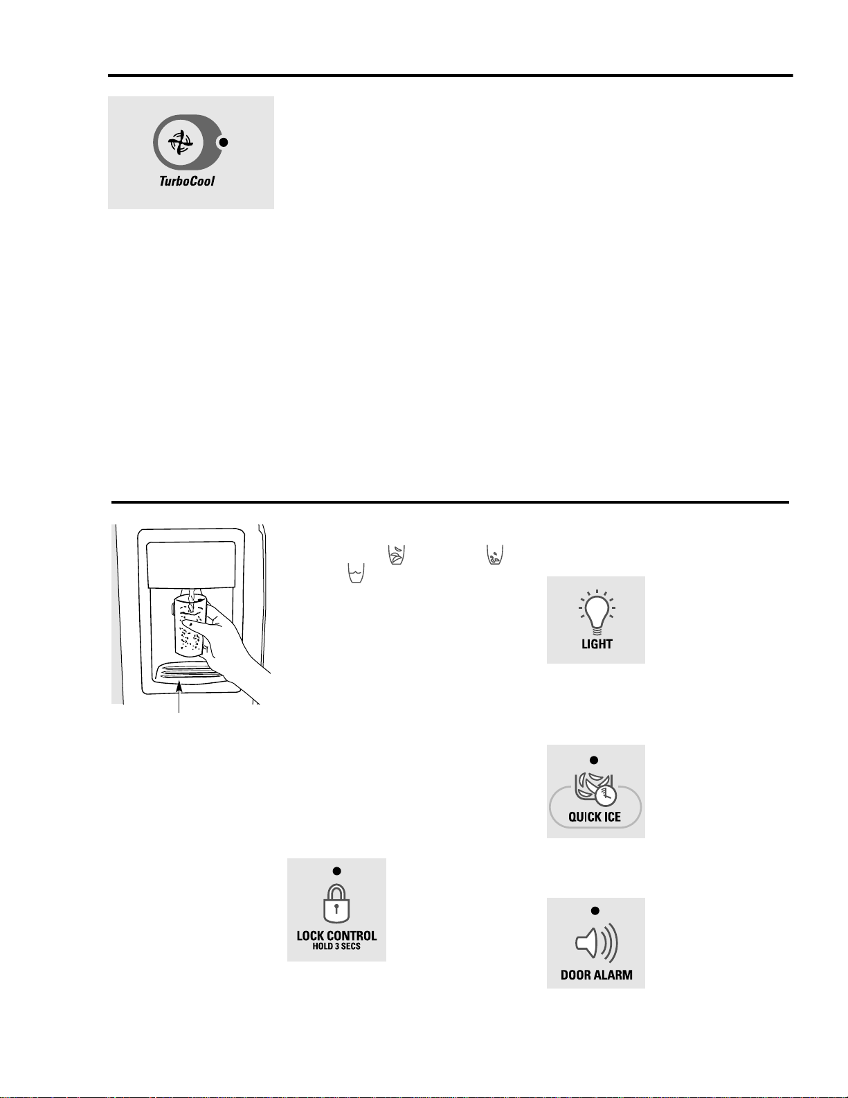
About TurboCool.
™
How it Works
TurboCool rapidly cools the refrigerator
compartment in order to more quickly
cool foods. Use TurboCool when adding a
large amount of food to the refrigerator
compartment, putting away foods after they
have been sitting out at room temperature
or when putting away warm leftovers. It can
also be used if the refrigerator has been
without power for an extended period.
Once activated, the compressor will turn on
immediately and the fans will cycle on and
off at high speed as needed for eight hours.
The compressor will continue to run until
the refrigerator compartment cools to
approximately 34°F (1°C), then it will cycle
on and off to maintain this setting. After 8
hours, or if TurboCool is pressed again, the
refrigerator compartment will return to
the original setting.
How to Use
Press TurboCool. The refrigerator
temperature display will show TC.
After TurboCool is complete, the
refrigerator compartment will return
to the original setting.
NOTES: The refrigerator temperature
cannot be changed during
TurboCool.
The freezer temperature is not
affected during TurboCool.
When opening the refrigerator
door during TurboCool, the fans
will continue to run if they have
cycled on.
About the ice and water dispenser. (on some models)
To Use the Dispenser
Select CUBED ICE , CRUSHED ICE
or WATER .
Press the glass gently against the top of
the dispenser cradle.
The spill shelf is not self-draining.
To reduce water spotting, the shelf and
its grille should be cleaned regularly.
If no water is dispensed when the refrigerator is
first installed, there may be air in the water line
system. Press the dispenser arm for at least two
minutes to remove trapped air from the water
line and to fill the water system. To flush out
impurities in the water line, throw away the first
six glassfuls of water.
CAUTION: Never put fingers or any other
objects into the ice crusher discharge opening.
Locking the Dispenser
Press the LOCK CONTROL
pad for 3 seconds to
lock the dispenser and
control panel. To
unlock, press and
hold the pad again
for 3 seconds.
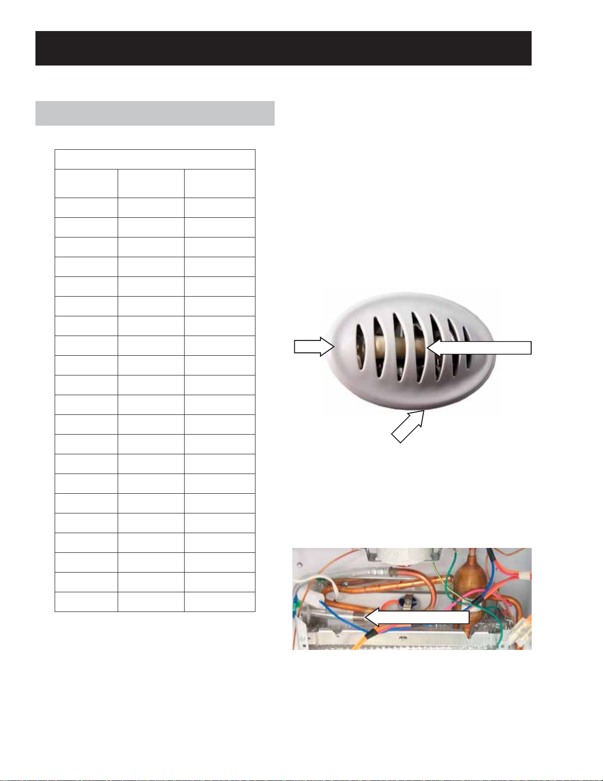
Dispenser Light
This pad turns the night
light in the dispenser
on and off. The light
also comes on when
the dispenser cradle is
pressed. If this light
burns out, it should be
replaced with a 6 watt
12V maximum bulb.
Quick Ice
When you need ice
in a hurry, press this
pad to speed up ice
production. This will
increase ice production
for the following
48 hours or until you
press the pad again.
Door Alarm
To set the alarm, press
this pad until the
indicator light comes
on. This alarm will
sound if either door is
open for more than
3 minutes. The light
goes out and the
beeping stops when
you close the door.
Spill Shelf
– 9 –
Page 10

Dispenser Light
The LIGHT pad turns the dispenser light on and
off. When the light is turned off, it will fade out.
The dispenser light will come on automatically
when the dispenser cradle is depressed and will
fade out 5 seconds after it is released. The LIGHT
pad will not turn off the light during dispensing.
Dispensing Functions
The water, crushed ice, and cubed ice functions
are controlled by the main control board. To
select a function, press the appropriate pad on
the dispenser. The LED will light to identify the
selection.
To dispense ice cubes or crushed ice, choose
the appropriate pad and depress the dispenser
cradle. The solenoid and linkage assembly will
open the ice chute duct door to dispense the
ice. If cubed ice is selected, a solenoid located
behind the ice bucket will lift a rod along the side
of the bucket. This rod pulls a fl apper away from
the cutter blades, allowing cubes to bypass the
ice crusher. The dispenser duct door will remain
open for 3 seconds after dispensing to allow all
ice to clear the chute.
The dispenser light will come on automatically
when the dispenser cradle is depressed and will
fade out 5 seconds after it is released.
Dispenser Lock
When the dispenser system is locked, no
dispenser command will be accepted. This
includes the dispenser cradle and will prevent
accidental dispensing that may be caused
by children or pets. If a pad or the cradle is
depressed with the system locked, it will be
acknowledged with three pulses of the LOCK
LED accompanied by an audible tone.
To lock or unlock communication between the
dispenser and main control board, press the
LOCK pad and hold it for 3 seconds. The LOCK
LED will fl ash while the LOCK pad is pressed.
When the communication is locked, the LOCK
LED will be illuminated.
The status of other functions selected prior to the
initiation of the lock feature will be displayed. If
the lock is engaged while a mode is active, the
LED will remain on until that mode times out.
If the lock is engaged when the fi lter timer
expires, the LED will come on but cannot be reset
until the lock is turned off.
The lock feature will be restored in the event of a
power disruption.
Liner Protection Mode
The dual evaporator model has separate liner
protection modes for each section. The specifi c
evaporator fan (freezer or fresh food) will start
and run on high speed if the door has been open
for 3 minutes.
This mode is controlled by 2 timers. Timer #1
monitors door-open time. A 3-minute door-open
count begins when the door is opened. If 3
minutes elapse before the door is closed, the liner
protection mode will become active. Once the
door is closed, timer #1 resets and liner protection
mode goes into standby. In standby, normal
fan operation resumes and timer #2 begins a
3-minute door-closed count. If 3 minutes elapse
without a door opening, liner protection mode will
completely deactivate. If a door is opened within
the timer #2 door-closed count, the remaining
time in the door-closed count will be deducted
from the timer #1 door-open count.
– 10
Page 11
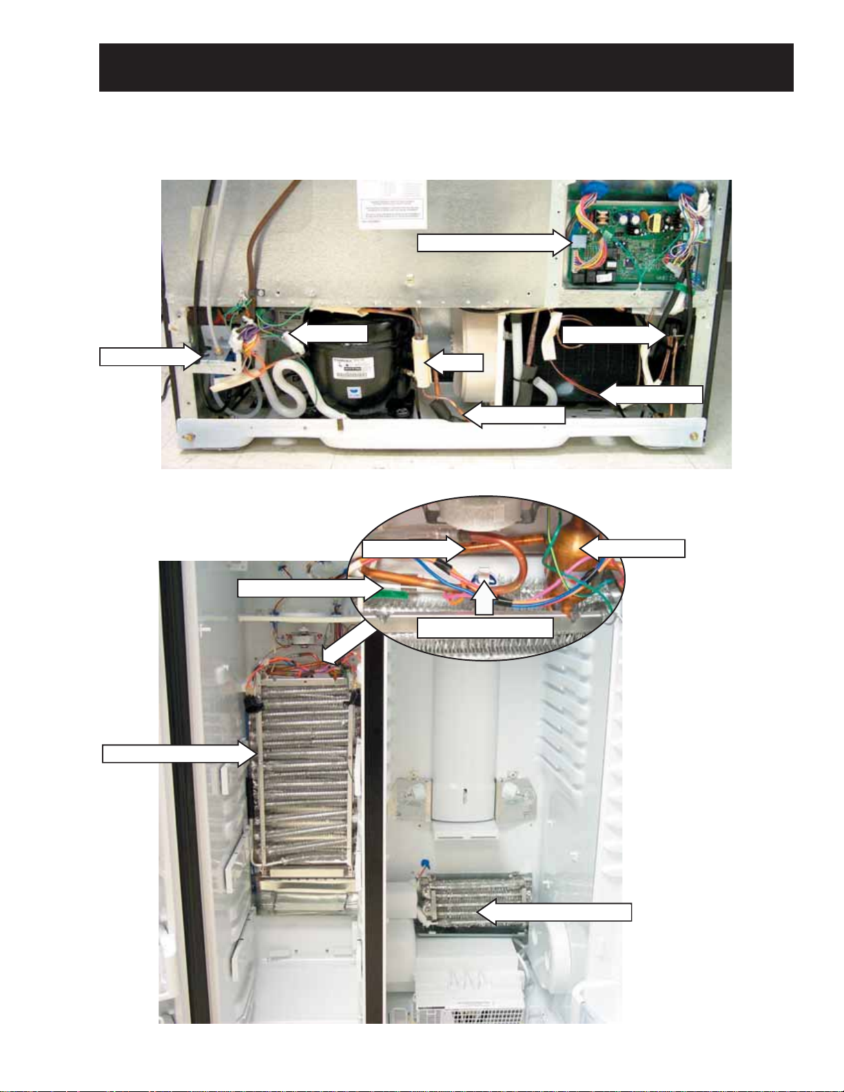
Rear View
Components Locator Views
Main Control Board
Water Valve
Front View
Inverter
Evaporator Thermistor
Check Valve
Over Temp Thermostat
3-Way Valve
Drier
Condenser
Jumper Tube
Accumulator
Note: The
check valve and
accumulator are
part of the freezer
evaporator and
are not available
separately.
Freezer Evaporator
Fresh Food Evaporator
– 11 –
Page 12
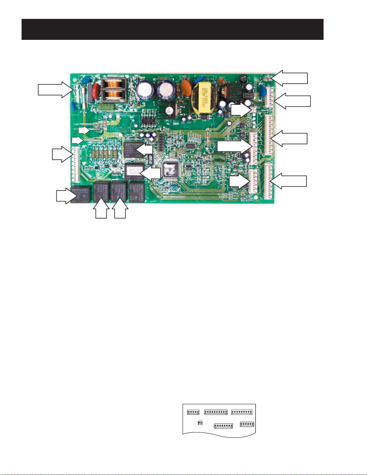
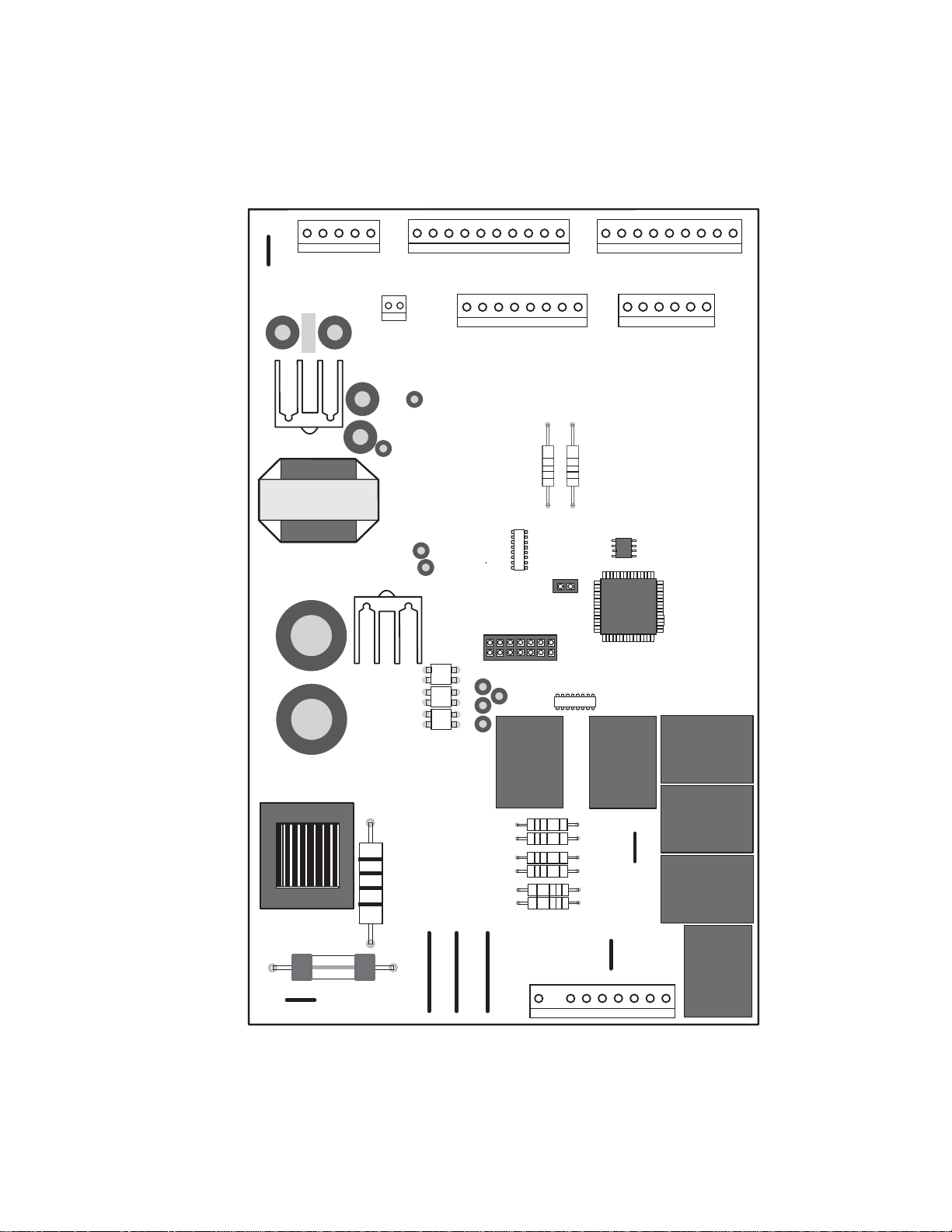
Main Control Board
J1 or J10
J9
J11
J7
Control Board Connector Locator
J15
K4
K5
J2 or J13
J5
J2 or J13
J4 or J16
J3 or J10
J1 or J14
K2K1K3
J1 or J10 - Earth (Ground)
J2 or J13 - Earth (Ground)
J5 - Custom Cool
J7 - Neutral, Door Switches, Custom Cool
Heater, Water Valve, Crusher Solenoid,
Auger Motor
J9 - Defrost Heater
J3 or J10 - 3-Way Valve
J11 - Line (L1)
J2 or J13 - Model Selector, Fan Common,
Evaporator Fan, Condenser Fan,
Fresh Food Fan, Custom Cool Fan
J1 or J14 - Fresh Food Thermistor, Freezer
Thermistor, Fresh Food Evaporator
Thermistor, Freezer Evaporator
Thermistor, Model Selector
J15 - Inverter
J4 or J16 - Temperature Control Board
K1 - Auger
K2 - Crusher
K3 - Water
K4 - Defrost
K5 - Custom Cool
Some of the low voltage DC
connector labeling on this model
may differ from other models. The
function and diagnostics for these
connectors are identical for all
models.
– 12
J4 or J16
J3 or J10
J2 OR J13
J1 or J14
Page 13
Comm. Common
Comm. +12V
Comm. 2-Way Digital
3-Way valve - Gray & White
3-Way valve - Black
3-Way valve - Red
3-Way valve - Yellow
3-Way valve - Orange
FF Thermistor
FF Evaporator Thermistor
Model Selector
+5V
FZ Thermistor
FZ Evaporator Thermistor
Model Selector
EARTH
J4 or J16
J2 or J13
5
1
1
J3 or J10
1
J15
1
J2 or J13
10
1
J1 or J14
8
J5
9
1
6
+5V
Fan +12V
Inverter Output
Inverter Common
Fan Common
Model Selector
Condenser Fan
Evaporator Fan
Fresh Food Fan
Custom Cool Fan
Evaporator Fan (RPM)
J19
1
J6
2
Custom Cool Thermistor
Custom Cool Dual Damper +
Custom Cool Dual Damper -
Custom Cool Single Damper -
Custom Cool Single Damper +
EARTH
J1 or J10
K4
DEFROST
Not Used (Wire ends in cabinet)
Defrost Heater
Line (L1)
J8
J9
J11
J7
Neutral
FZ Door Switch
K5
CUSTOM COOL
J12
Not Used
J18
Not Used
Water Valve
FF Door Switch
Custom Cool Heater
Crusher Solenoid
Auger Motor Interlock
K7
NOT
K3
WATER
K2
CRUSHER
K1
1
Auger Motor
USED
AUGER
– 13 –
Page 14
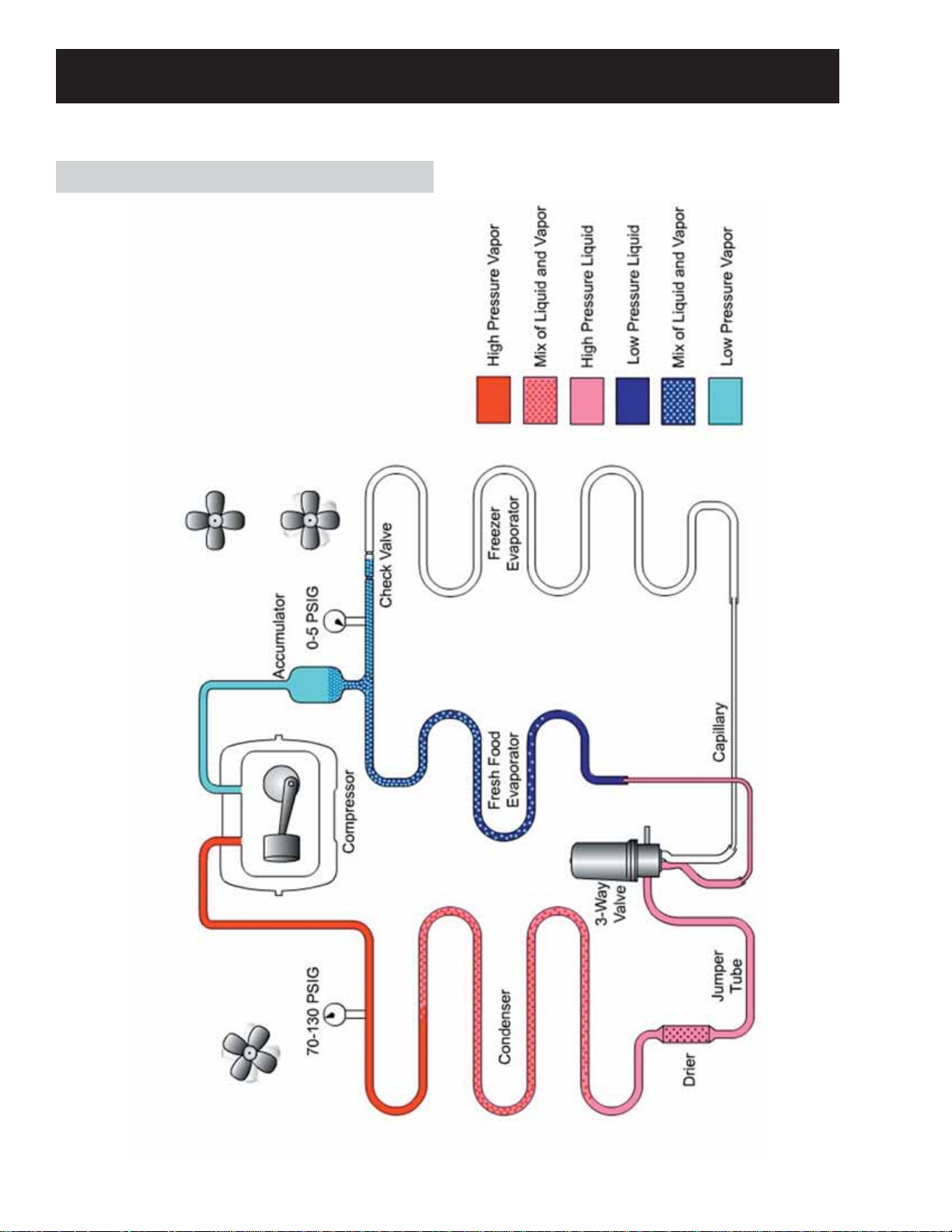
Fresh Food Section Cooling
Refrigeration System
Freezer Fan Off
Fresh Food Fan Running
Condenser Fan Running
– 14
Page 15
Freezer Section Cooling
Freezer Fan Running
Fresh Food Fan Off
Condenser Fan Running
– 15 –
Page 16
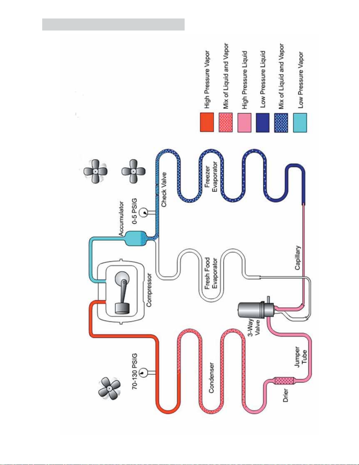
Fresh Food and Freezer Section Cooling
Freezer Fan Running
Fresh Food Running
Condenser Fan Running
– 16
Page 17

Evacuation and Charging Procedure
WARNING:
• Before cutting or using a torch on
refrigerant tubes, recover the refrigerant
from the system using approved recovery
equipment.
4. Open the ball valve. Recover the purge/
sweep charge using the recovery pump and
the refrigerator compressor until a 20-in.
vacuum is attained. Close the ball valve and
remove the recovery hose.
5. Charge the system with the exact amount of
R-134a refrigerant specifi ed.
• Never charge new refrigerant through the
purge valve. This valve is always located
on the high pressure side of the system.
• Never apply heat from any source to a
container of refrigerant. Such action will
cause excessive pressure in the container.
• Always wear goggles when working with
refrigerants and nitrogen holding charge
in some replacement parts. Contact with
these gases may cause injury.
1. Attach the hose from the R-134a charging
cylinder to the process tube port on the
compressor.
2. Evacuate the system to a minimum 20-in.
vacuum using the refrigerator compressor and
recovery pump, which is attached to the new
drier assembly.
3. Turn off the recovery pump. Close the ball
valve on the hose connected to the high-side
port connection. Add 3 ounces of R-134a
refrigerant to the system. Let the refrigerator
operate and circulate the refrigerant for 5
minutes.
6. Disconnect the power cord to the refrigerator.
This allows the pressure to equalize. After
3 to 5 minutes, the low side pressure will be
positive and then the hose-to-charging port
can be disconnected.
7. Using an electronic leak detector, check
all brazed joints and both schrader ports.
Reinstall caps to schrader.
– 17 –
Page 18
Components
Thermistors
Temperature
(°F)
-40 -40 166.8 kΩ
-31 -35 120.5 kΩ
-22 -30 88 kΩ
-13 -25 65 kΩ
-4 -20 48.4 kΩ
5 -15 36.4 kΩ
14 -10 27.6 kΩ
23 -5 21 kΩ
32 0 16.3 kΩ
41 5 12.7 kΩ
Thermistor Resistance
Temperature
(°C)
Resistance in
Kilo-Ohms
Fresh Food and Freezer Thermistors
The fresh food and freezer thermistors (part #
WR55X10025) are located in the mullion dividing
the fresh food and freezer compartments.
Note: The fresh food and freezer thermistors are
removed in the same manner.
To remove the thermistor cover, insert a fl at-blade
screwdriver under the front of the cover and
gently lift at the bottom edge until it releases from
the compartment wall.
Insert
Thermistor Cover
50 10 10 kΩ
59 15 7.8 kΩ
68 20 6.2 kΩ
77 25 5 kΩ
86 30 4 kΩ
95 35 3.2 kΩ
104 40 2.6 kΩ
113 45 2.2 kΩ
122 50 1.8 kΩ
131 55 1.5 kΩ
140 60 1.2 kΩ
Note: To accurately test a thermistor, place the
thermistor in a glass of ice water (approximately
33°F) for several minutes and check for
approximately 16K Ω.
Lift
Freezer Evaporator Thermistor
The freezer evaporator thermistor (part #
WR55X10025) is clipped to the top coil of the
freezer evaporator. See Freezer Evaporator for
accessing instructions.
Evaporator Thermistor
– 18
Page 19
Fresh Food Evaporator Thermistor
The fresh food evaporator thermistor (part #
WR55X10025) is located in an aluminum thermal
block on the back of the evaporator. It is attached
to the fresh food evaporator by a wire tie. See
Fresh Food Evaporator for accessing instructions.
If the fresh food evaporator thermistor is either
open or shorted, the main control board defaults
to a fi xed defrost cycle of 1 hour at high speed
fan.
Thermal Block
Thermistor
Insert the new thermistor into the thermal block.
Add RTV102 silicone to hold the thermistor in
place. Make certain to wire tie the thermal block
back to the evaporator.
Fresh Food Evaporator Fan
A variable speed
12 VDC motor
is mounted in
front of the fresh
food evaporator.
The fan and
evaporator cover
are replaced
as a complete
assembly.
Barbs on the molded housing hold the thermistor
in the thermal block.
Barbs
Replacement
Should the evaporator thermistor require
replacement, splice a new thermistor into the
harness using plastic bell connectors (part #
WR01X10466). Fill the connector with RTV102
silicone as shown in the illustration.
When activated, the fresh food evaporator fan
recirculates the air in the fresh food compartment,
providing cooling independent of the freezer
evaporator fan.
The main control board gathers information from
the fresh food thermistors to determine when, and
at what speed, fan operation should occur.
A constant 13.6 VDC is provided to the fan from
the main control board and switching occurs on
the neutral side.
Speed is regulated by pulse width modulation on
the common side of the fan. When operating, the
common side of the circuit is pulsed open and
closed. This pulsing produces effective voltage
being received at the motor, which is equivalent to
a reduction in voltage. Fan speed is selected and
maintained by the main control board regulating
the length and frequency of the 13.6 VDC pulse.
13.6 VDC
12 VDC
0 VDC
High Speed (12 VDC measured)
– 19 –
13.6 VDC
10 VDC
13.6 VDC
9 VDC
0 VDC
0 VDC
Medium Speed (10 VDC measured)
Low Speed (9 VDC measured)
Page 20

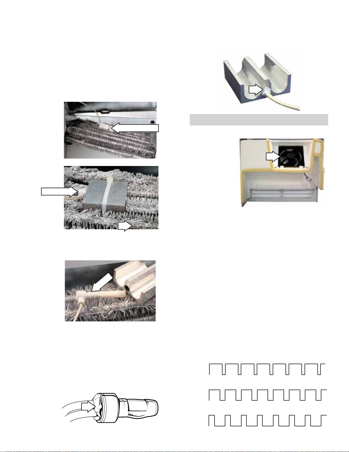
Freezer Evaporator Fan
The position of the fan blade in relation to the
shroud is important.
5/16" ± 0.03
1.0" ± 0.05 Target
The evaporator fan is the same fan used on
previous models; however, a signifi cant difference
is that the main control board neither requires
nor receives input from the fan feedback/rpm
(blue) wire. The fan utilizes a permanent magnet,
4 pole, DC motor that operates at three different
speeds: high, medium, and low.
The speed of the fan is controlled by the voltage
output from the main control board. Voltage
output from the main control board to the fan
is 13.6 VDC; however, to regulate the speed of
the fan, the main control board uses pulse width
modulation (PWM).
When operating, voltage is sent in pulses (much
like a duty cycle) as opposed to an uninterrupted
fl ow. This pulsing of 13.6 VDC produces effective
voltage being received at the motor, which is
equivalent to a reduction in voltage.
13.6 VDC
9.5 VDC
0 VDC
13.6 VDC
8 VDC
0 VDC
13.6 VDC
6.5 VDC
0 VDC
Blade tip
Orifice
Air Flow
Motor
High Speed (9.5 VDC measured)
Medium Speed (8 VDC measured)
Low Speed (6.5 VDC measured)
Fan speed is selected and maintained by the
main control board regulating the length and
frequency of the 13.6 VDC pulse. Temperature
can cause some fan speed variation. Fan speed
can vary +/- 5%, depending on the temperature,
with higher temperatures causing slightly higher
speeds.
The evaporator fan has a 4-wire connection:
White Wire (DC Common)
The white wire is the DC common wire used
for testing. During repairs, DC polarity must be
observed. Reversing the DC polarity causes a
shorted motor and/or board.
Red Wire (Supply)
Each motor uses an internal electronic controller
to operate the motor. Supply voltage from
the main control board remains at a constant
13.6 VDC.
Blue Wire (Feedback/RPM)
On previous Arctica models, the blue wire
reported rpm (speed) information to the main
control board for speed control purposes. On this
model, the board does not require or read any
feedback information from the fan motor.
Yellow Wire (Signal)
The yellow wire is the input wire from the main
control board. The main control board provides
6.5 VDC effective voltage for low speed, 8 VDC
effective voltage for medium speed, and 9.5 VDC
effective voltage for high speed. The fan operates
in low speed only when the fresh food thermistor
is satisfi ed.
Note: When testing these motors:
• You cannot test with an ohmmeter.
• DC common is not AC common.
• Verify 2 voltage potentials:
a. Red to white - power for internal controller
b. Yellow to white - power for fan
• Observe circuit polarity.
• Motors can be run for short periods using a
9 volt battery. Connect the white wire to the
negative (-) battery terminal only. Connect
the red and yellow wires to the positive (+)
battery terminal.
– 20
Page 21

Condenser Fan
The fan is mounted in the machine compartment
with the no-clean condenser. The fan and
fan shroud are mounted on one end of the
condenser, and the other end of the condenser is
blocked.
When the fan is operating, air is pulled from
the center of the condenser, drawing air in
through the coils. The air is then exhausted over
the compressor and out the right side of the
refrigerator.
Inlet air is available through the left front
and left rear of the machine compartment. A
rubber divider strip underneath the refrigerator
divides the inlet and outlet sides of the machine
compartment.
Rear
Divider Strip
Front
1/2"
Fan
0.375"
Housing
Motor
The rear access cover must be tightly fi tted to
prevent air from being exhausted directly out of
the rear of the machine compartment, bypassing
the compressor.
The condenser fan is mounted with screws to a
fan shroud and mounting bracket that is attached
to the condenser.
Condenser fan speed corresponds with
compressor speed (low, medium, high) to
minimize pressure variations in the sealed
system except when the freezer temperature is
20°F above the set point. If this condition exists
(such as during initial startup), the condenser
fan operates at super high speed while the
compressor operates at medium speed.
The speed of the fan is controlled by the voltage
output from the main control board. Voltage
output from the control board to the fan is
13.6 VDC; however, to regulate the speed of
the fan, the main control board uses pulse width
modulation (PWM).
When operating, voltage is sent in pulses (much
like a duty cycle) as opposed to an uninterrupted
fl ow. This pulsing of 13.6 VDC produces effective
voltage being received at the motor, which is
equivalent to a reduction in voltage.
Fan speed is selected and maintained by the
main control board regulating the length and
frequency of the 13.6 VDC pulse.
Air Flow
0.50" ± 0.05
Bracket
– 21 –
Page 22

Temperature can cause some fan speed
variation. Fan speed can vary +/- 5%, depending
on the temperature, with higher temperatures
causing slightly higher speeds.
Condenser fan speed is controlled by Pulse
Width Modulation (PWM), the same method used
to control fan speeds for the evaporators.
13.6 VDC
12.0 VDC
0 VDC
Super High Speed (12.0 VDC measured)
13.6 VDC
10.5 VDC
0 VDC
High Speed (10.5 VDC measured)
Fresh Food Normal Defrost
The fresh food section cools until the fresh food
thermistor is satisfi ed.
13.6 VDC
7.5 VDC
0 VDC
Medium Speed (7.5 VDC measured)
13.6 VDC
5.5 VDC
0 VDC
Low Speed (5.5 VDC measured)
Defrost Cycles
Fresh Food Evaporator Defrost Cycle
The refrigerator utilizes a forced air cycle defrost
method (no electric heater) to remove frost from
the fresh food evaporator. Fresh food air that is
above freezing temperature circulates thru the
coil and melts any accumulated frost. Note that
during fresh food defrost, the compressor may
still be running, cooling only the freezer section.
If both freezer and fresh food thermistors are
satisfi ed, the compressor cycles off. If the freezer
still requires cooling, the main control board
rotates the 3-way valve to stop refrigerant fl ow to
the fresh food evaporator. Even though refrigerant
fl ow has stopped in the fresh food evaporator, the
fresh food fan continues to run at low speed.
The system is designed to run the fan until the
fresh food evaporator thermistor reaches 35°F.
Once this temperature is reached, the fan
continues to run for an additional 5 minutes.
Under normal conditions, the defrost time takes
approximately 30 minutes. The maximum time
the fan runs in low speed is 60 minutes. If the
evaporator thermistor has not reached 35°F after
60 minutes, the control switches to extended
defrost #1.
– 22
Page 23

Fresh Food Extended Defrost #1
Fresh Food Forced Defrost
Occasionally there may be excessive frost
on the evaporator coil. This can be attributed
to numerous door openings, extremely high
humidity, poor door gasket seal, etc. If the normal
defrost fan time exceeds 60 minutes, the fan
switches to high speed. The control continues to
monitor the fresh food evaporator thermistor for
35°F. When 35°F is reached, the fan runs for an
additional 5 minutes at high speed. The fan can
run up to an additional 30 minutes at high speed,
trying to reach 35°F. After 90 total minutes of fan
time (60 at low speed and 30 at high speed), if
the fresh food evaporator is still below 35°F, the
control will switch to extended defrost #2.
Fresh Food Extended Defrost #2
If the fresh food fan has been operating for 90
minutes, the main control searches for a fresh
food thermistor temperature above 52°F. If the
fresh food thermistor is above 52°F, the main
control board assumes there is a problem reading
the fresh food evaporator thermistor, ends the
defrost cycle and returns to normal cooling.
If the fresh food thermistor is less than 52°F, the
main control board assumes there is refrigerant
leaking through the 3-way valve, keeping the
fresh food evaporator cold during the defrost
process while the freezer evaporator is cooling.
The main control board shuts off the compressor
and runs the fresh food fan at high speed until
two conditions are met: the evaporator thermistor
reaches 35°F and the fresh food thermistor is
2½F° above the set point. As in the other cycles,
the fan continues to run for an additional 5
minutes after the 35°F evaporator temperature is
reached.
If the main control board senses the fresh food
section has been cooling for 45 minutes, it
immediately stops the refrigerant fl ow through
the fresh food evaporator. The main control
board changes the position of the 3-way valve
if cooling is still required in the freezer, or turns
the compressor off if the freezer is satisfi ed. The
fresh food fan operates on high speed until the
evaporator reaches 35°F, plus an additional 5
minutes after the evaporator reaches 35°F.
To prevent the refrigerator from going into forced
defrost when fi rst installed or after a power failure,
the control will disregard the 45 minute time limit
if the freezer temperature is above 20°F.
Note: If the fresh food evaporator thermistor is
either open or shorted and the 35°F cutoff cannot
be determined, the main control board defaults to
a fi xed defrost cycle of 1 hour at high-speed fan.
Freezer Defrost Cycle
The freezer evaporator utilizes a defrost heater
to remove frost from the coil. The control board
determines the length of time the heater is
energized. It does this by monitoring the freezer
evaporator thermistor. Once the temperature
of the thermistor reaches 75°F, the control
cycles the defrost heater off. A bi-metal safety
thermostat provides a backup in the event the
evaporator thermistor fails. The safety thermostat
prevents the temperature from exceeding 140°F.
Note: During the freezer defrost cycle, the
compressor does not operate, even if the fresh
food section is above the set point.
– 23 –
Page 24

Inverter
•
The inverter is accessed from the back of the
refrigerator.
•
It is located on the left side of the compressor
behind the water valve.
• The water valve must be removed to access
the inverter.
To remove the Inverter
1
1. Remove the
the inverter in place.
/4-in. hex-head screw that holds
Caution: It may be necessary to bend the
process tube in order to remove the inverter. If
it is necessary to bend the process tube, use
extreme caution.
Inverter Viewed From the Front
Inverter
2. Rotate the inverter counterclockwise and
slide it forward to release the tabs from the
mounting bracket.
Inverter Front
Process Tube
Inverter Shown with Cover Removed
Compressor Lead Wires
Line-In
N
Signal Wire Connector from Main Board
L1
WARNING: When the refrigerator is plugged in,
120 VAC is always present at the inverter.
Back Tab
Right Side Tab
Left Side View
Mounting Bracket
Back View
Back Tab
Note: Certain voltmeters will not be able to read
voltage output from the inverter. If no voltage
or erratic voltage is measured, it does not
necessarily indicate a faulty inverter.
The inverter receives 120 VAC line-in from the
power supply. The inverter converts this singlephase, 60 Hz, 120 VAC into 3-phase, 230 VAC,
with frequency variations between 57 Hz and 104
Hz. This voltage is delivered to the compressor
through 3 lead wires. Each wire will carry identical
voltage and frequency.
Note: The compressor leads must be connected
to measure voltage output. If the compressor
wires are not connected, or if an open occurs in
one of the 3 lead wires or in the compressor, the
inverter will stop voltage output.
– 24
Page 25

When checking inverter voltage output, connect
the test-meter leads to any 2 of the 3 compressor
lead wires at the inverter plug (plug should
be connected). The same reading should be
measured between any 2 of the 3 wires.
The inverter controls compressor speed
by frequency variation and by Pulse Width
Modulation (PWM). Changing frequency and
PWM will cause an effective voltage between 80
and 230 VAC to be received at the compressor.
• Low speed (1710 rpm) - 57 Hz
• Medium speed (2100 rpm) - 70 Hz
• High speed (3120 rpm) - 104 Hz
The inverter receives commands from the main
control board. The main control board will send
a PWM run signal from the J15 connector of
between 4-6 VDC effective voltage to the inverter
(all wires must be connected). The inverter will
select compressor speed (voltage output) based
on this signal.
The main control board will only send a run signal
to the inverter when the compressor should be
on.
Note: When measuring signal voltage (from the
main control board) at the inverter, a reading
of 4-6 VDC will be measured with all wires
connected. If the inverter wiring is disconnected,
the board output will measure between 10-12
VDC.
The inverter will monitor compressor operation
and if the compressor fails to start or excessive
current draw (4 amps maximum) is detected,
the inverter will briefl y stop voltage output.
The inverter will then make 12 consecutive
compressor start attempts (once every 12
seconds). After 12 attempts, if the compressor
has not started, an 8-minute count will initiate.
After the 8-minute count, the inverter will attempt
to start the compressor again. If the compressor
starts, normal operation will resume. If the
compressor fails to start, this process will be
repeated. Removing power to the unit will reset
the inverter count. When power is restored, the
inverter will attempt to start the compressor within
8 seconds.
The inverter has a built-in circuit protection to
guard against damage from a failed or shorted
compressor. However, if a failed compressor is
diagnosed, order a new compressor and inverter.
If the compressor fails to start after replacement,
replace the inverter.
– 25 –
Page 26

Inverter Compressor
Caution: Do not attempt to direct-start the
compressor. The compressor operates on a
3-phase power supply. Applying 120 VAC to the
compressor will permanently damage the unit. It
is not possible to start the compressor without an
inverter.
The compressor is a reciprocating, variable
speed, 4-pole type. It operates on 3-phase, 80 to
230 VAC within a range of 57 to 104 Hz.
Note: Certain voltmeters will not be able to read
voltage output or frequency from the inverter.
Compressor wattages at various speeds are:
• LOW - 65 watts
• MED - 100 watts
• HIGH - 150 watts
The compressor is controlled by the inverter,
which receives its signal from the main control
board. Varying the frequency to the inverter
changes the compressor speed.
• 3°F to 5°F above refrigerator set point medium speed.
• 5.5°F to°7 F above refrigerator set point - high
speed.
Note: The compressor will run at medium speed
if the freezer temperature is 20°F or more above
the setpoint.
The use of 3-phase power eliminates the need
for the PTCR relay, capacitor, and individual
start and run windings; therefore, the start,
run and common pins found on conventional
compressors are not applicable on this 3-phase
model. Compressor pin functions are identical
and compressor lead wire confi guration is of no
importance. A resistance of 9Ω to 11Ω should be
read between any 2 of the 3 pins. Should an open
occur in the compressor winding or should one
of the compressor lead wires become open or
disconnected, the inverter will stop voltage output
to the compressor.
High compressor torque enables the compressor
to start against high pressure in the sealed
system. When power has been disconnected
from an operating unit, the high torque will enable
the compressor to start immediately upon power
restoration.
AC
J15-2
J15-1
Main Control
Board
BROWN
BLACK
TAB 1
10
10
COMPRESSOR
BLACK
BLUE
10
BROWN
INVERTER
WHITE
RED
ORANGE
ORANGE
WHITE
Compressor speed is based on the temperature
set point in conjunction with the specifi c cabinet
temperature. Speeds are selected according to
the following cabinet temperatures, with freezer
temperature being the primary:
• 7°F to 19.5°F above freezer set point = high
speed.
• 4.5°F to 6.5°F above freezer set point =
medium speed.
• 1°F to 4°F above freezer set point = low
speed.
• 1°F to 2.5°F above refrigerator set point = low
speed.
Compressor and sealed system operation is
extremely smooth and cool. The compressor
exterior may be room temperature while
operating; therefore, a running unit may be
diffi cult to detect.
RED
To verify that the compressor is running:
Disconnect power from the unit and place a hand
on the compressor. Reconnect power and feel for
a vibration when the compressor tries to start. It
may take up to 8 seconds before the compressor
attempts to start.
Note:
When ordering a replacement compressor,
•
order both the compressor and inverter.
Replace the compressor fi rst. If, after
compressor installation, the compressor fails
to start, replace the inverter.
When servicing the compressor, it is important
•
to dress the wiring to keep low voltage DC
wiring and 120 VAC wiring separate.
– 26
Page 27

3-Way Valve
The 3-way valve is located beneath the main
control board in the machine compartment and
is accessed from the back of the refrigerator. It is
composed of a magnetic coil and a valve body.
Two ¼-in. hex-head screws mount the valve to
the cabinet.
Make certain that rubber gaskets are installed
•
on mounting bracket to reduce vibration.
3-Way Valve Coil
The 3-way valve coil receives 12 VDC pulses
from the main board to change the position of the
valve. The pulses come too quickly to measure
with a volt meter.
The 3-way valve coil has a resistance value of
approximately 46 ohms that can be measured
between the coil pins.
Rubber Gaskets
Three copper tubes connect to the 3-way
•
valve.
One jumper tube connects from the drier to
•
the inlet on the valve.
A freezer capillary and a fresh food capillary
•
connect to the other two tubes on the valve.
Coil
Jumper Tube to Drier
Capillary Tube to Fresh
Food
Valve Body
Capillary Tube to
Freezer
– 27 –
Page 28

3-Way Valve Body
The valve body contains a cam, rotor and
•
magnet.
The rotor and cam are grooved to rotate with
•
the magnet.
Valve Rotation
The pulses of the valve coil cause the magnet
•
to rotate inside the valve body.
As the magnet rotates, it moves the cam at
•
the bottom of the valve.
The entire valve body has refrigerant fl owing
•
through it when the compressor is operating.
Use care not to damage the top of the valve
•
body when installing the coil on the valve.
A locating pin is used to correctly align the
•
valve body in the valve coil.
Failure to fully seat the valve in the coil or to
•
align it correctly with the pin can cause the
system to stop cooling.
Rotor
Valve Body
Cam
Magnet
Stop Point
(Home Position)
Magnet
Note: The 3-way valve comes only as a complete
assembly. Exploded view is for reference only.
The cam opens or covers the ports to the
capillary tubes.
Capillary Tube
Ports
– 28
Page 29

Testing the 3-Way Valve
The valve returns to “home” at the end of
every freezer defrost cycle and whenever the
refrigerator is reconnected to power.
To test the valve, disconnect the refrigerator from
power for at least 10 seconds, place a fi nger on
top of the valve and reconnect power.
Replacing the 3-Way Valve
Parts Needed:
•
3-Way Valve (part # WR57X10053)
•
Thermal Paste (part # WX5X8927)
•
Drier Assembly (part # WR86X93)
•
Process valve (part # WJ56X61)
The main control overdrives the valve to the
“home” position.
You should be able to feel the valve move as it
returns to the home position .
If movement is present, the main board and valve
coil are operating correctly.
When replacing a 3-way valve, note the black
mark on the freezer outlet tube. Make certain to
mark the freezer capillary by placing a piece of
tape on the capillary, 6-8 inches from the valve.
This will aid in installing the capillaries in the
correct outlet tubes.
– 29 –
INLET
FRESH FOOD
OUTLET
FREEZER
OUTLET
Black Mark
Page 30

1. Unplug the refrigerator.
Fresh Food
Outlet
Black
Mark
Inlet
Freezer
Outlet
2. Remove the rear access cover and evacuate
the sealed system. (See Evacuation and
Charging Procedure.)
3. Remove the valve body from the valve coil by
carefully pressing down on top of the valve
body.
Press
Here
5. Connect the new jumper tube to the inlet tube
of the new 3-way valve.
6. Prepare the taped capillary tube, and insert
it into the 3-way valve freezer outlet port
(identifi ed with black mark or tape).
7. Prepare the remaining capillary tube and
insert it into the 3-way valve fresh food outlet
port.
4. Tape the freezer capillary tube 6 inches below
the brazing joint. Score and break the two
capillary tubes below the brazing joints.
Valve Body
Common
Tube
Black
Mark
Brazing
Joints
Jumper Tube
Two Capillary
Tubes
Tape Here
FF Capillary
Tube
Break
Here
Break
Here
FZ Capillary
Tube
8. Apply a liberal amount of thermal paste to
the base of the three tubes on the new valve.
Apply a wet cloth to the top of the valve to
help keep the valve cool.
Apply a Wet Cloth
to Top of Valve to
Help Keep Valve Cool
Thermal
Paste
– 30
Page 31

9. Angle the torch so the fl ame is not directed
towards the valve body when brazing the
three joints.
10. Remove the thermal paste residue and dry
the valve body thoroughly. Install the valve
body into the coil.
Freezer Evaporator
The following components must be removed
in the appropriate order to access the freezer
evaporator:
1. Remove the ice bucket, shelves, and drawers.
Note: If necessary, use an adjustable pliers to
carefully install the valve body into the coil. DO
NOT depress on the top of the valve body. See
photo.
11. Remove the old drier by un-brazing or
cutting the condenser loop (halo) as close
as possible to the drier. Install the new drier
assembly (part # WR86X93).
2. Slide the air duct panel upward to remove.
3. Remove the light bulb cover and light bulbs.
4. Remove the four 1/4-in. hex-head screws that
hold the auger assembly in place.
5. The auger motor wiring is connected in two
places:
Note: If necessary, use the condenser loop
extension tubing (part # WR97X238).
Jumper Tube
12. Install the process valve (part # WJ56X61).
Clean and inspect all joints.
13. Evacuate and charge the system. Use original
factory charge quantity of R-134a. (See
Evacuation and Charging Procedure.)
14. Reinstall the rear access cover.
a. Disconnect the top connector.
Disconnect
b. Pull the auger motor assembly forward
and disconnect the second connector.
Disconnect
– 31 –
Page 32

6. Loosen the 2 screws that hold the icemaker
assembly in place and slide it out of the
freezer compartment.
10. Remove the 4 hex-head screws that hold the
evaporator fan shroud in place ( Fig. 1 and
Fig. 2).
Top Hex-head Screws
Fig. 1
7. Loosen the 3 screws on the icemaker bracket,
and slide it out of the freezer compartment.
8. Unclip the light bulb sockets from their
mounting holes and disconnect the sockets.
Note: The bottom hex-head screws are hidden
under the bottom of the evaporator fan shroud.
Bottom Hex-head Screws
Fig. 2
11. Unclip the auger connector plug from the
evaporator fan shroud. Slide the evaporator
fan shroud down and out of the freezer
compartment.
9. Remove the 4 hex-head screws that hold the
freezer evaporator cover in place. Carefully
pull the evaporator cover out of the freezer
compartment.
Auger Connector Plug
– 32
Page 33

12. Disconnect the fan wiring harness
(Disconnect 1). Disconnect the over
temperature thermostat/light bulb wiring
harness (Disconnect 2).
13. Remove the 2 hex-head screws that hold the
fan bracket in place.
Replacing Freezer Evaporator Using the
Brazing Method
Parts Needed:
•
Freezer Evaporator (part # WR85X10061)
•
Drier Assembly (part # WR86X93)
•
Access Tube (part # WJ56X61)
•
Heat Shield Kit (part # WX5X8926)
Disconnect 1
Disconnect 2
Screw
Screw
14. Remove the ground clip from the evaporator
frame.
15. Unclip the evaporator thermistor.
16. Slide the over-temperature thermostat/light
bulb wiring harness out of the fan bracket.
17. Remove the fan bracket.
Caution: A heat shield kit is required for this
procedure to prevent damage to the plastic
interior (liner) of the freezer compartment.
Note: If it is determined that the epoxy joints (the
transition joint between the aluminum and copper
jumper) on the freezer evaporator assembly are
defective, then
LOKRING connectors can be used
to repair the joints. Refer to Pub. No. 31-9067 for
more LOKRING information.
1. Unplug the refrigerator.
2. Remove the rear access cover and evacuate
the sealed system.
3. Remove components necessary to expose
the evaporator. (See
Freezer Evaporator.)
4. Remove the ice bucket, icemaker, auger
assembly, fan motor housing, and fan motor.
5. Note the location of thermistor and thermostat
on top of old evaporator and remove.
6. Remove heater from bottom of evaporator
and discard. Bundle remaining wires and tape
high on the back wall of freezer.
Evaporator Thermistor
Ground Clip
Note: When replacing the evaporator thermistor,
cut the thermistor wires and splice the new
thermistor using bell connectors. Always use
RTV102 silicone to seal the end of the connector
from moisture.
7. Apply a liberal amount of thermal paste to
suction line where it enters the rear wall of
freezer.
8. Insert the brazing shield behind the joint of the
accumulator top and suction line to protect the
liner.
9. Use torch to heat the joint of the accumulator
top, separate the suction line and accumulator
top and clean the suction line surface (Fig. 1
and 2).
10. Using the tubing cutter, cut fresh food
evaporator jumper (right side) tube about 2
inches from the joint outlet end of the fresh
food evaporator. Score and break the capillary
tube about 2 inches from the end of freezer
evaporator inlet jumper (left side) (Fig. 1 and
2).
– 33 –
Page 34

r
FZ
Evaporator
Inlet
Jumper
Brazing Shield
Fig. 1
Top of
Accumulator
Evaporato
Jumper
12. Modify replacement evaporator to accept the
5
/
-in. fresh food evaporator jumper.
16
FF
Modify
Here
11. Loosen the hex-head screws that hold the
evaporator in place. Note locations of the
foam blocks at sides of old evaporator. These
are needed for proper airfl ow. Remove the
foam blocks and save for new evaporator
installation. Remove old evaporator.
Loosen Hex-
Head Screws
Suctio
n
Tube
Line
Capillary
Tube
Cut
Here
Heat
Here
2"
13. Install the new evaporator and tighten all
mounting screws.
14. Connect tubes between top of accumulator
and suction line. Connect tubes between
fresh food evaporator and freezer evaporator
(right side). Insert the capillary tube.
15. Check that the thermal paste is still on the
suction line where it enters the rear wall of the
freezer. If not, apply paste. In addition, apply
thermal paste around epoxy joints on the new
evaporator to prevent the heat from damaging
joint integrity.
16. Protect the freezer fl oor from molten
solder during brazing. Braze suction line to
accumulator on new evaporator. Angle torch
so that fl ame is directed away from rear wall
when brazing.
Remove
Screw
Fig. 2
FF
Evaporator
Outlet
Cut
Here
2"
17. Move the brazing shield behind the capillary
joint and braze the capillary tube.
– 34
Page 35

18. Move the brazing shield behind the fresh food
jumper to the freezer evaporator. Braze the
jumper tube joint. Remove the brazing shield.
Clean and inspect all joints.
19. Remove the old drier by cutting the halo loop
as close as possible to the drier. Install the
new drier assembly (part # WR86X93) making
sure that there is suffi cient space between the
tubing.
Replacing Freezer Evaporator Using the
LOKRING Method
Parts Needed:
Freezer Evaporator (part # WR85X10061)
•
Drier Assembly (part # WR86X93)
•
Access Tube (part # WJ56X61).)
•
LOKRING Connectors (part # WR97X10021)
•
20. Install the access tube. Clean and inspect
joints.
21. Replace the heater supplied with the
evaporator. Reinstall foam blocks, thermostat
and thermistors. Dress wiring.
22. Evacuate and charge the system. Use original
factory charge quantity of R-134a. (See
Evacuation and Charging Procedure.)
23. Replace all component parts in the freezer.
24. Reinstall the rear access cover.
Note: If it is determined that the epoxy joints (the
transition joint between the aluminum and copper
jumper) on the freezer evaporator assembly are
defective, then LOKRING connectors can be used
to repair the joints. Refer to Pub. No. 31-9067 for
more LOKRING information.
1. Follow steps 1 through 6 under
Freezer Evaporator Using the Brazing Method.
Replacing
2. Using the tubing cutter, cut the freezer
evaporator jumper of the check-valve
assembly (top) as close as possible to the
joint of the copper jumper. Cut the jumper
tube (left side) on the inlet of the freezer
evaporator (capillary joint) as close as
possible to the epoxy joint.
Suction
Cut
Here
Tube
Line
– 35 –
Capillary
Tube
Cut
Here
FF
Evaporator
Outlet
Page 36

3. Loosen the hex-head screws that hold the
evaporator in place. Note locations of the
foam blocks at sides of old evaporator. These
are needed for proper airfl ow. Remove the
foam blocks and save for new evaporator
installation. Remove old evaporator.
Loosen HexHead Screws
4. Modify replacement evaporator to use
LOKRING connectors.
a. Using the tubing cutter, cut the jumper
tube (top) at the outlet end of the freezer
evaporator. Leave as much of the straight
tube portion as possible from the joint of
the check-valve assembly. Discard the
check-valve assembly.
5. Install the new evaporator and tighten all
mounting screws.
6. Remove the old drier by cutting the halo
loop as close as possible to the drier. Install
the new drier assembly (make sure there is
suffi cient space between the tubing).
7. Install the access tube. Clean and inspect
joints.
8. Replace the heater supplied in the kit.
Reinstall foam blocks, thermostat and
thermistors. Dress the wiring.
9. Evacuate and charge the system. Use original
factory charge quantity of R-134a. (See
Evacuation and Charging Procedure.)
10. Replace all component parts in the freezer.
11. Reinstall the rear access cover.
b. Using the tubing cutter, cut the jumper
tube (left side) on the inlet end of the
evaporator (capillary joint) about 3 inches
from epoxy joint. Make two joints using
the LOKRING connectors for 5/
-in. copper
16
to copper joints.
Cut
Here
Cut
Here
– 36
Page 37

Fresh Food Evaporator
1. Remove the custom cool drawer and
necessary drawers and covers above the
custom cool drawer, to expose the evaporator
cover housing.
2. Remove the water line coil cover.
Note: The water line coil cover is slotted. To
remove it, slide the water line coil cover toward
the door opening.
3 Remove the 3 Philips-head screws that hold
the fresh food evaporator fan cover in place.
Screw
Screw
Screw
5. Loosen the 2 Phillips-head screws that hold
the fresh food evaporator in place.
Screw
Screw
6. Carefully lift and pull the fresh food evaporator
forward. Cut the tie strap that holds the
thermistor block in place.
7. Remove the evaporator thermistor and block
from the evaporator.
Evaporator Cover
Water Line Coil Cover
4. Carefully pull the cover forward, then
disconnect the fresh food evaporator fan.
Disconnect
FF Evaporator Fan
– 37 –
Page 38

Replacing Fresh Food Evaporator Using
the Brazing Method
7. Pull the evaporator away from the liner and
remove the thermistor from the aluminum
block attached to the rear of the evaporator.
Parts Needed:
•
Fresh Food Evaporator (part # WR85X10060)
•
Drier Assembly (part # WR86X93)
•
Access Tube (part # WJ56X61)
•
Heat Shield Kit (part # WX5X8926)
Caution: A heat shield kit is required for this
procedure to prevent damage to the plastic
interior (liner) of the freezer compartment.
Note: If it is determined that the epoxy joints (the
transition joint between the aluminum and copper
jumper) on the freezer evaporator assembly are
defective, then
to repair the joints. Refer to Pub. No. 31-9067 for
more LOKRING information.
1. Unplug the refrigerator.
2. Remove the rear access cover and evacuate
the sealed system. (See Evacuation and
Charging Procedure.)
3. Remove components necessary to expose
both the freezer and fresh food evaporators.
(See Freezer Evaporator and Fresh Food
Evaporator.)
LOKRING connectors can be used
8. Look into the freezer compartment and locate
the epoxy joints on the tubes leading to the
fresh food evaporator. (These joints will be
located on the right hand side of the freezer
evaporator.)
Epoxy
Joints
4. Remove the 2 foam tubes that are wire tied
to the inlet and outlet tubes of the fresh food
evaporator.
5. Remove the Styrofoam block that is inserted
into the opening in the mullion wall and
discard. A replacement is provided.
6. Loosen the 2 screws that attach the fresh
food evaporator to the liner.
Styrofoam
Block
Wire
Ti
Foam
T
ubes
e
Loosen 2 Screws
9. To allow easier access to the epoxy joints,
pull them away from the side of the freezer
evaporator into the freezer compartment.
10. Using the tube cutter, cut the 5/16 -in. OD
copper tube as close to the epoxy joint as
possible. Score and break the capillary tube
as close to the braze joint as possible.
11. Remove the fresh food evaporator.
12. Install new fresh food evaporator.
– 38
Page 39

13. Connect the capillary tube to the inlet tube
of the evaporator. Connect the 5/16 -in.
OD copper tube to the outlet tube of the
evaporator (remove any excess length as
required to obtain the correct fi t).
14. Apply a liberal amount of thermal paste
around both epoxy joints to prevent heat from
damaging joint integrity.
15. Install a metal brazing shield between the
joints and the plastic liner.
16. Protect the freezer fl oor from molten solder
during brazing.
17. Angle torch so that the fl ame is directed away
from the plastic liner. Braze both joints. Clean
and inspect joints. Remove the brazing shield.
18. Clean thermal paste off the joints. Dress the
joints to the right of the freezer evaporator
so the freezer evaporator cover can be
reinstalled without interference.
19. Reinsert the thermistor into the aluminum
block on the rear of the new fresh food
evaporator.
20. Attach the evaporator to the fresh food liner
using the original screws. Ensure that the
drain pan is properly positioned. Install a new
Styrofoam block into the hole of the mullion.
Attach foam tubes to evaporator inlet/outlet
tubes using wire tie provided.
21. Remove the old drier by cutting the condenser
loop as close as possible to the drier. Install
the new drier assembly, making sure that
there is suffi cient space between the tubing.
Install the access tube on the compressor.
22. Evacuate and charge the system. Use original
factory charge quantity of R-134a. (See
Evacuation and Charging Procedure.)
Replacing Fresh Food Evaporator Using
the
LOKRING Method
Parts Needed:
Drier Assembly (part # WR86X93)
•
Process Tube (part # WJ56X61
•
LOKRING Connectors (part # WR97X10021)
•
Note: If it is determined that the epoxy joints
(transition joint between the aluminum and copper
jumper) on the freezer evaporator assembly are
defective, then LOKRING connectors can be used
to repair the joints. Refer to Pub. No. 31-9067 for
more LOKRING information.
1. Follow steps 1 through 9 under Replacing
Fresh Food Evaporator Using the Brazing
Method.
2. Using the tube cutter, cut both copper tubes
as close to the epoxy joint as possible. Leave
as much 5/16 -in. tubing as possible for a good
LOKRING connection.
3. Remove the fresh food evaporator.
4. Modify replacement evaporator to use
LOKRING connectors.
a. Using the tubing cutter, cut the jumper
tube at the outlet end of the evaporator
2 inches from the epoxy joint.
b. Cut the jumper tube on the inlet end of the
evaporator (capillary joint) 11/2 inches from
the epoxy joint. Make two joints using the
LOKRING connectors for
copper joints.
Inlet Tube
Outlet Tube
5
/
-in. copper to
16
23. Replace all component parts in both the
freezer and the fresh food compartments.
24. Reinstall the rear access cover.
– 39 –
1-1/2"
Epoxy
Joints
2"
Page 40

5. Reinsert the thermistor into the aluminum
block on the rear of the new fresh food
evaporator.
6. Attach the evaporator to the fresh food liner
using the original screws. Ensure that drain
pan is properly positioned. Install a new
Styrofoam block into the hole of the mullion.
Attach foam tubes to the evaporator inlet/
outlet tubes using wire tie provided.
7. Remove the old drier by cutting the condenser
loop as close as possible to the drier. Install
the new drier assembly (make sure there is
suffi cient space between the tubing). Install
the process tube on the compressor.
8. Evacuate and charge the system. Use original
factory charge quantity of R-134a. (See
Evacuation and Charging Procedure.)
Check Valve
Check Valve
A nylon piston inside the check valve fl oats
•
back and forth, depending upon refrigerant
fl ow.
The check valve prevents refrigerant from
•
fl owing back into the freezer evaporator.
9. Replace all component parts in both the
freezer and the fresh food compartments.
10. Reinstall the rear access cover.
Accumulator
The accumulator collects any liquid refrigerant
•
left in the evaporator before it enters the
suction line.
The liquid refrigerant pools in the bottom
•
of the accumulator until it is drawn into the
compressor as a vapor.
The accumulator comes as a part of the
•
freezer evaporator. It is not available
separately.
When the main control rotates the 3-way
•
valve for fresh food only cooling, the check
valve will prevent refrigerant from fl owing
in the freezer evaporator (refrigerant will
naturally fl ow to the coldest area).
The check valve is only available with a new
•
freezer evaporator.
Caution: Do not attempt to replace only the
check valve. The nylon piston in the check valve
is extremely heat sensitive.
– 40
Page 41

Troubleshooting
Control Diagnostics
Enter the diagnostic mode by pressing both the freezer temperature (COLDER and WARMER) pads
and the refrigerator temperature (COLDER and WARMER) pads simultaneously. All four pads must
be held for approximately 3 seconds. Blinking "0"s in both displays indicate the refrigerator has
entered the test mode.
Enter the appropriate display numbers
as shown below and press any pad other
than the temperature pads to activate
that test mode. Not all test modes are
available on all models.
Freezer
Display
02
04
0 6 Temperature Control LED Test
0 7 Control and Sensor System Test
0 8 Duct Door Test
Fresh
Food
Display
Diagnostics Results Comments
Communication check between
Temperature Control and Main Control
Communication check between
Dispenser Control and Main Control
"P" on freezer
display if OK. "F" if
problem is found.
"P" on freezer
display if OK. "F" if
problem is found.
All LEDs light.
Pressing the
corresponding pad
turns off the LED.
Checks each
thermistor and
displays "P" for pass
and "0" for fail.
Opens the dispenser
duct door for 10
seconds, then
closes.
See Note 3.
See Note 1.
Test can be
performed with door
open.
– 41 –
Page 42

Freezer
Display
1 0 Dampers Test
1 1 Fan Test
1 2 100% Run Time
1 3 Prechill Test
1 4 Defrost Test
1 5 Main Control Reset
1 6 Exit Diagnostics Mode
Fresh
Food
Display
Diagnostics Results Comments
Double damper will
open, close after
10 seconds, pause
briefl y, then single
damper will open for
10 seconds.
Cycles through each
fan for 5 seconds.
Sealed system on
100% of the time.
Times out after 1
hour.
Starts Prechill mode.
Unit returns to
normal on its own.
Toggles on the
defrost cycle. See
Note 2.
Causes a system
reset.
Causes a
temperature control
board reset.
Test will not start for
20 seconds after
pad is depressed.
Must press again
to turn heaters off.
See Note 2.
Note 1: Display order is #1 = Fresh Food Evaporator Thermistor, #2 = Fresh Food Thermistor, #3 =
Custom Cool Thermistor, #4 = Freezer Evaporator Thermistor, #5 = Freezer Thermistor.
Thermistor test results are: P = Pass, 0 = Fail, S = Short to 5 VDC, B = Bad amplifi er (replace main
control).
Note 2: You must enter the defrost test again to toggle the defrost heater off at the end of the test. The
heater will not come on if the evaporator thermistor is above 70°F.
Note 3: To exit the Temperature Control LED Test, press both refrigerator temperature pads (COLDER
and WARMER) simultaneously for 3 seconds.
– 42
Page 43

WHITE
RED
ORANGEORANGE
Schematic
ORANGEORANGE
FF COMPARTMENT
TEMPERATURE
CONTROL
J3-3 J3-2 J3-1
AC
SMART
TROLLEY
J15-2
J15-1
BLACK
ORANGE
BROWN
(COMM)
ORANGE
BLACK
J4-2 J4-1
RED
BLACK
BLUE
WHITE
BLUE
(COMM)
ORANGE
RED
THERMOSTAT
OVERTEMPERATURE
PINK
INVERTER
HEATER
DEFROST
BROWN
BLUE
10
10
10
COMPRESSOR
BLUE
TAB 1TAB 2J7-6J7-7J7-4J7-3J7-2J7-1J7-9J7-5 TAB 4
R=21.15
ORANGE
ORANGE
LIGHT (TOP)
FRESH FOOD
PURPLE
+12V RED
PURPLE PURPLE
FF SWITCH
BROWN
TAN
ORANGE
LIGHT (MID)
FRESH FOOD
PURPLE
PINK
FF THERMOSTAT
BLACK/WHITE
CC FAN
CUSTOM COOL LIGHT
YELLOW
ORANGE
FREEZER LIGHT
PURPLE
FREEZER DOOR
RED
YELLOW/BLACK
WHITE/SILVER (COMM)
ORANGE
RED
INTERLOCK
BROWN
RED/WHITE
BLUE/WHITE (MODEL)
ORANGE
(AUGER IMPUT)
BLUE (RPM)
INSIDE
DIAGRAM
ICEMAKER
BROWN
ORANGE
ORANGE
WATER
WHITE WHITE WHITE
HOUSING
BROWN BROWN
VALVE
YELLOW
ICEMAKER
YELLOW
MAIN CONTROL BOARD
R=180
WHITE
ORANGEORANGE
ORANGE
R=3.34
AUGER
R=91
CUBE
SILVERSILVERSILVER
BEIGE BEIGE
BEIGE
J-12
+5V BLUE
BLUE
ORANGE
ORANGE
HEATER
TO CUSTOM COOL
BLUE/WHITE
BLUE/WHITE
WHITE/RED
THERMISTOR FZ EVAP.
WHITE/RED
R=404
RED/WHITE
YELLOW
J1-1J5-6J5-4J5-3J5-1J5-2J5-5 J1-2 J1-3 J1-4 J1 -5 J2-1 J2-2 J2-3 J2-4 J2-5 J2-6 J2-7 J2-8 J4-3
BLUE/RED
PINK
BROWN
YELLOW/BLACK
SINGLE DAMPER
YELLOW
DUAL DAMPER
LINE VOLTAGE
LOW VOLTAGE DC
CLASS 2 CIRCUITS
DUCT SOLENOID
FREEZER DOOR
TO HTR
14
RED
RED
BLACK
RED
BLACK
BLACK
RED
J4-1J4-2J4-3J4-6
BLACK
J1-1 J1-2
10
BLUE
BLUE
YELLOW
DISPLAY BOARD
J2-4 J2-3 J2-2
RED
GRAY
REDBLACK
BLACK
DEP. SWITCH
10
RED
WHITE YELLOW
DEP. SWITCH
10
FF FAN
COMPRESSOR
WHITE
BLUE
YELLOW
RED
WHITE
YELLOW
RED
EVAP. FAN
COND. FAN
J3-6
WHITE + GREY
J3-7
BLACK
3-Way Valve
J3-8
YELLOW
WHITE/BLUE
THERMISTOR FZ
WHITE/BLUE
WHITE/BLACK
THERMISTOR CC
THERMISTOR FF
WHITE/BLACK
WHITE/GREEN
FF EVAP.
THERMISTOR
WHITE/GREEN
J3-10
J3-9
ORANGE
RED
– 43 –
3-Way Valve
Page 44

Illustrated Parts
– 44
Page 45

– 45 –
Page 46

– 46
Page 47

– 47 –
Page 48

– 48
Page 49

– 49 –
Page 50

– 50
Page 51

– 51 –
Page 52

– 52
Page 53

– 53 –
Page 54

VIEW NUMBER CATALOG NUMBER DESCRIPTION QUANTITY
0001 31-51518 PM MINI WIRING MANUAL 1
0001 49-60238 PM GUIDE OWNERS 1
0006 WR12X10561 HANDLE SOFT TOUCH INSERT 2
0010 WR01X10065 SCR 8-18 BA POR 5/8 SS 15
0011 WR38X10245 TRIM RECESS WH 1
0012 WR02X10649 STOP DOOR WH 2
0014 WR24X10156 GASKET DOOR FZ WH 1
0015 WR02X10638 CAM CLOSURE FZ WH 1
0016 WR02X10637 CAM CLOSURE FF WH 1
0023 WR71X10499 MODULE FZ UPPER 1
0025 WR71X10500 MODULE FZ SEAT 1
0026 WR71X10495 GUIDE ICE 1
0027 WR01X10387 SCR 8-18 AB OVP 7/8 SS 2
0031 WR17X11654 GRILLE RECESS WH 1
0036 WR62X10020 SOLENOID ASM 1
0045 WR02X8818 RETAINER RECESS DOOR 2
0056 WR02X10675 BULB RECS 12V 1
0058 WR17X11081 HOUSING SHIELD DISP WH 1
0061 WR02X9561 LAMP SOCKET 1
0062 WR17X11653 DOOR RECESS ASM 1
0063 WR02X10585 SPRING RECESS DOOR 1
0067 WR17X10706 CRANK DOOR RECESS 1
0069 WR17X11264 FUNNEL ICE DISP WH 1
0070 WR17X11265 EXTENSION FUNNEL ICE WH 1
0070 WR49X10075 EXTENSION FUNNEL ICE WH 1
0072 WR23X10224 SWITCH 1
0074 WR02X10584 SPRING FUNNEL 1
0080 WR02X11330 UNION CONNECTOR 1
0093 WR55X10469 INTERFACE DISP ASM 1
0095 WR17X11481 WINE & BEVERAGE RACK 1
0103 WR24X10155 GASKET DOOR FF WH 1
0104 WR04X10129 LENS NAMEPLATE 1
0106 WR22X10042 DOOR DAIRY CLEAR 1
0107 WR22X10041 COMPARTMENT DAIRY 1
0109 WR71X10594 MODULE SHELF FF 1
0110 WR71X10297 MODULE SHELF FIXED FF 1
0111 WR71X10298 INSERT MODULE FF FIXED 1
0112 WR02X10639 SNUGGER 2
0115 WR71X10253 MODULE SHELF FF 2
0116 WR22X10043 TRIM DAIRY COMPARTMENT 1
0122 WR71X10256 MODULE SUPPORT FZ 2
– 54
Page 55

VIEW NUMBER CATALOG NUMBER DESCRIPTION QUANTITY
0123 WR71X10255 MODULE SUPPORT FZ 1
0124 WR21X10053 BASKET WIRE TILTOUT FZ 1
0125 WR21X10054 BASKET WIRE TILTOUT FZ 2
0127 WR71X10380 MODULE SHELF INSERT 3
0151 WR01X1554 SCR 8-18 AB IHXW 1/2 S 14
0159 WR14X10067 FOAM STRIP SE ADH 1
0160 WR14X10068 FOAM STRIP SE ADH 1
0161 WR17X11257 DUCT EXTENSION FZ ASM 1
0164 WR14X10164 GASKET PLENUM 1
0165 WR14X10167 GASKET MOTOR COVER 2
0167 WR17X11477 PLENUM FAN EVAPORATOR 1
0168 WR02X10674 BRACKET FZ TOWER LOWER 1
0175 WR01X10035 SCR 8-18 AB IHW 5/8 S 23
0177 WR01X10240 8-8X7/16 TORX PAN HEAD 9
0178 WR01X10241 8-18X13/16 TROX PAN HEAD 9
0179 WR12X10624 HANDLE 1
0180 WR71X10527 SHELF FIXED FZ 1
0181 WR38X10214 TRIM SHELF FZ 2
0182 WR71X10498 SHELF ADJUSTABLE FZ 1
0184 WR21X10040 BASKET FZ LONG 3
0185 WR12X10625 HANDLE 3
0186 WR21X10041 BASKET WIRE FZ SHORT 1
0189 WR17X10945 SPACER 3
0190 WR72X10066 SUPPORT SLIDE BASKET RH 1
0191 WR72X10067 SUPPORT SLIDE BASKET LH 1
0194 WR02X10810 COVER L.H. 3
0195 WR02X10811 COVER R.H. 3
0196 WR72X10068 SLIDE & BRACKET ASM LH 3
0197 WR72X10069 SLIDE & BRACKET ASM RH 3
0198 WR72X10070 SLIDE LINER 6
0200 WR17X11702 COVER FF AIR TOWER 1
0201 WR17X11703 EPS FF TOWER 1
0200 WR17X11805 COVER FF AIR TOWER 1
0202 WR14X10188 GASKET TOWER FF 2
0203 WR17X11711 COVER WATER FILTER 1
0204 WR02X10676 FRAME SUPPORT PINS 6
0202 WR17X11805 GASKET TOWER FF 2
0208 WR01X10431 NUT 6-32 UN 1
0210 WR74X10131 GUARD WIRING 1
0212 WR02X10689 GROMMET BASE GRILLE 2
0213 WR17X11803 COVER EVAPORATOR FRONT 1
0214 WR14X10153 GASKET EVAP COVER 2
– 55 –
Page 56

VIEW NUMBER CATALOG NUMBER DESCRIPTION QUANTITY
0210 WR74X10131 GUARD WIRING 1
0215 WR01X10211 BRACKET FZ TOWER UPPER 2
0217 WR32X10154 DIAL PAN CHILL 1
0218 WR02X10665 LINKAGE PAN CHILL 1
0219 WR02X10664 SHUTTER PAN CHILL 1
0220 WR02X11851 EPS PAN CHILL 1
0221 WR02X11852 DISCHARGE PAN CHILL 1
0222 WR02X10666 KNOB PAN CHILL 1
0224 WR02X11853 FOAM STRIP SE ADH 1
0225 WR02X11426 TUBE DRAIN 1
0226 WR02X11848 TUBE DRAIN 1
0227 WR23X10337 HARNESS AC FZ INTERMEDIA 1
0228 WR85X10061 LOW SIDE ASM FZ 1
0229 WR02X10552 CLIP EVAP THERMISTOR 1
0230 WR51X10042 HEATER & BRACKET ASM 1
0231 WR02X10669 BLOCK EVAP SEAL 3
0232 WR17X10811 SHIELD ASM TROUGH 1
0233 WR55X10026 SENSOR TEMP FZ 1
0234 WR02X10647 GRILLE SENSOR 2
0235 WR02X10668 SHUNT SENSOR 2
0237 WR55X10028 SENSOR TEMP FF 1
0240 WR50X10028 DEFROST THERMOSTAT 1
0233 WR55X10025 SENSOR TEMP FZ 1
0241 WR55X10025 SENSOR TEMP FF 1
0247 WR17X10812 ORIFICE FAN ASM 1
0248 WR14X10168 GASKET MOTOR COVER 2
0237 WR55X10025 SENSOR TEMP FF 1
0249 WR14X10165 GASKET PLENUM 1
0250 WR14X10069 FOAM STRIP SE ADH 1
0256 WR17X11713 SHIELD LIGHT FF 1
0257 WR02X10663 STAND OFF 4
0258 WR17X11480 SHIELD LIGHT FZ 1
0259 WR17X11712 LIGHT SHIELD 1
0261 WR13X10137 HINGE BTM & PIN ASM WH 1
0263 WR02X10648 PIN HINGE BTM ADJ HOLLOW 1
0268 WR01X10210 SCREW MOBILITY 3.5 2
0270 WR17X11506 GROMMET AND TUBE ASM 1
0278 WR02X10636 MOBILITY FRONT ASM 2
0280 WR02X10640 CAP CORNER OC WH 2
0288 WR74X10071 GRILL BASE ASM AWH 1
0306 WR02X10833 SCREW MOBILITY 23 2
– 56
Page 57

VIEW NUMBER CATALOG NUMBER DESCRIPTION QUANTITY
0312 WR02X10827 MOBILITY ASSY BACK-BIS 2
0320 WR01X10315 NUT AUGER FRT DISP 1
0321 WR01X1367 RETAINER RING E 1
0325 WR17X10717 HOUSING CRUSHER DISP 1
0326 WR01X1366 WASHER 1
0328 WR02X4143 PIN DEFLECTOR DISP 1
0328 WR02X4561 SPRING ICE DEFLECTOR 1
0328 WR17X10703 DEFLECTOR ICE DISP 1
0329 WR17X11486 WIRE ACTUATOR DISP 1
0321 WR1X1367D RETAINER RING E 1
0330 WR02X10583 SPRING DEFLECTOR 1
0325 WR17X11505 HOUSING CRUSHER DISP 1
0331 WR02X10580 RETAINER SPRING 1
0326 WR1X1366D WASHER 1
0332 WR17X1361 BLADES MOVING DISP 1
0333 WR17X1362 BLADES MOVING DISP 1
0334 WR17X1363 BLADES MOVING DISP 1
0335 WR02X4139 SPACER CRUSHER MIDDLE 3
0337 WR02X4138 SPACER CRUSHER STATIONAR 2
0342 WR02X10691 STATIONARY BLADES ASM 1
0345 WR17X11453 COVER CRUSHER 1
0350 WR17X11479 AUGER HELIX DISP 1
0352 WR30X10046 BUCKET ICE DISP 1
0354 WR17X11483 BUCKET AND AUGER ASM 1
0355 WR17X11459 CUP DRIVE 1
0356 WR17X11458 PLATE HELIX LOCK 1
0357 WR17X11457 HELIX 1
0358 WR01X10389 SCR 8-18 AB PHR 1/2 S 6
0359 WR72X10138 GLIDE BUCKET RH 1
0359 WR72X10139 GLIDE BUCKET LH 1
0361 WR17X11460 COVER MTR & SOLENOID 1
0362 WR02X10656 BRACKET ANGLE 2
0365 WR02X11534 DRIVE AUGER DISP 1
0366 WR01X10190 NUT J 1
0367 WR01X10198 SCR 8-18 TPT 1/4 5
0368 WR02X11336 BRACKET IM MOUNTING 1
0369 WR60X10125 MOTOR CRUSHER DISP 1
0371 WR01X10192 SCR 10-18 HI/LO HXW 1/2 2
0375 WR23X10330 HARNESS MOTOR & SOL 1
0377 WR02X7309 SADDLE SOLENOID 1
0378 WR62X0058 SOLENOID & ARM ASM 1
0379 WR17X1063 SHROUD SOLENOID 1
– 57 –
Page 58

VIEW NUMBER CATALOG NUMBER DESCRIPTION QUANTITY
0380 WR17X1064 PLUNGER SOLENOID 1
0381 WR02X4257 PIN SPIRAL 1
0382 WR02X4258 SPRING SOLENOID LINKAGE 1
0383 WR17X1065 COLLAR SOLENOID DISP 1
0384 WR17X1066 STIRRUP SOLENOID DISP 1
0385 WR02X4259 PIN SPIRAL 1
0386 WR02X11767 BOOT AUGER MOTOR INT 1
0387 WR17X11478 COVER BUCKET BOTTOM 1
0400 WR01X10209 WHEEL PAN COVER 8
0401 WR01X10214 SCR 10-16 PL PNP 5/8 SZN 8
0405 WR02X11254 DIFFUSER FF INLET LT 1
0405 WR02X11255 DIFFUSER FF INLET RT 1
0407 WR32X10339 PAN MIDDLE CHILL ASM 1
0409 WR32X10200 COVER PAN GLASS 1
0410 WR32X10197 COVER MIDDLE PAN 1
0413 WR02X10650 HUMIDITY CONTROL 1
0414 WR14X10059 GASKET PAN CRV FRONT 1
0417 WR14X10058 GASKET PAN CRV REAR 1
0418 WR02X10633 SLIDE MIDDLE PAN COVER 1
0421 WR55X10389 INTERFACE CUSTONER ASM 1
0433 WR02X9391 SOCKET & TERMINAL ASM 4
0434 WR02X10645 SOCKET LAMP 2
0435 40A15 LAMP 40 W 4
0437 60A LAMP 60 W 2
0447 WR02X10831 COVER HINGE FZ BK 1
0448 WR13X10214 HINGE TOP & PIN ASM FZ 1
0449 WR13X10215 HINGE TOP & PIN FF 1
0450 WR02X10832 COVER HINGE FF BK 1
0451 WR13X10126 HINGE BTM WH 1
0453 WR23X10209 HARNESS/TSTAT FF LT 1
0454 WR01X10212 NUT 8-32 2
0456 WR71X10595 BEZEL LIGHT FF 1
0470 WR32X10196 COVER TOP PAN ASM 1
0471 WR32X10338 PAN ASM TOP 1
0481 WR31X10036 TRAY CUSTOM COOL 1
0482 WR17X11787 WIREFRAME PAN 1
0487 WR32X10434 PAN FRAME ASM 1
0501 WR71X10296 SHELF SLIDEOUT ASM 2
0505 WR02X10662 STOP SHELF 3
0530 WR71X10294 SHELF TUCKAWAY ASM 1
0540 WR31X10038 COVER PAN ASM 1
0552 WR01X2022 SCREW 10
– 58
Page 59

VIEW NUMBER CATALOG NUMBER DESCRIPTION QUANTITY
0553 WR01X10314 SCREW HANDLE MTG 6
0580 WR72X10140 SLIDE AND BRACKET ASM 2
0581 WR72X10141 SLIDE LINER 2
0582 WR72X10142 SPACER SLIDE 2
0583 WR01X10399 SCR 8-18 AB HW 1/2 S 6
0602 WR01X1591 SCR 1/4-14 X 3/4 2
0608 WR23X10179 SWITCH LIGHT 1
0609 WR23X10175 SWITCH LIGHT 1
0610 WR60X10099 MOTOR DC EVAP FAN ASM 1
0611 WR02X10764 BRACKET EVAP FAN BTM 1
0612 WR02X10653 BRACKET ORIFICE FAN 1
0613 WR60X10075 BLADE EVAP FAN ASM 1
0614 WR02X10540 BUMPER LID 3
0615 WR02X10519 GROMMET EVAP FAN 2
0616 WR82X10093 COVER ACCESS 1
0618 WR02X11331 GROMMET EVAP FAN 2
0625 WR01X5278 CLAMP CABLE 2
0626 WR23X0108 HARNESS CORD POWER 1
0610 WR60X10043 MOTOR DC EVAP FAN ASM 1
0626 WR23X0108 POWER CORD 1
0628 WR17X11252 SHROUD CONDENSER 1
0650 WR60X10080 MOTOR DC COND FAN 1
0651 WR60X10049 BLADE COND FAN ASM 1
0652 WR02X10509 RING COMPRESSION 2
0653 WR02X10322 CAP DUST 1
0616 WR82X10071 COVER ACCESS 1
0683 WR02X11027 WIRE TIE 1
0686 WR01X10252 SCR 10-32 TT HXW 5/16 S 10
0690 WR01X1466 SCR 8-32 T HXW 3/8 S 7
0626 WR23X10300 HARNESS CORD POWER 1
0691 WR02X10593 BRACKET COND FAN (REAR) 1
0725 WR87X10064 INVERTER COMPRESSOR EMB 1
0626 WR23X10300 POWER CORD 1
0727 WR17X11503 SEPARATOR AIR HISIDE 1
0730 WR84X10022 CONDENSER ASSEMBLY 1
0650 WR60X10065 MOTOR DC COND FAN 1
0734 WR02X11262 COVER RELAY (EMB) 1
0736 WR02X8203 CLIP COMPRESSOR MOUNT 4
0737 WR02X10099 GROMMET 4
0740 WR86X10030 DRYER BIFURCATED HX9 1
0741 WR01X1779 STUD MTG COMPR 4
0749 WR17X11039 BAFFLE COND AIR 1
0750 WR01X1786 SCREW 10-32 TR 1/2 4
– 59 –
Page 60

VIEW NUMBER CATALOG NUMBER DESCRIPTION QUANTITY
0690 WZ5X158D SCR 8-32 T HXW 3/8 S 7
0751 WR17X10693 BASEPLATE HIGH SIDE 1
0753 WR02X10521 BRKT COND FAN (MTG) 1
0757 WR01X10193 SCR 10-32 SPECIAL 6
0758 WD02X0323 SCR 8-32 X 3/8 SPH 2
0762 WR02X11857 FOAM STRIP SE ADH 1
0764 WR02X9000 CLIP, COND MNT 2
0765 WR17X10763 BRACKET CONDENSER BAR 1
0775 WR17X10796 COVER WATER LINE 1
0734 WR02X11262 COVER RELAY (EMB) 1
0790 GWF FILTER CANISTER 1
0791 WR02X11705 CAP FILTER BYPASS 1
0792 WR17X11028 FILTER ASM AND TUBE 1
0800 WR57X10040 WATER VALVE 1
0801 WR55X10414 BOARD ASM MAIN CONTROL 1
0802 WR23X10382 HARNESS BOARD INDIV 1
0803 WR02X11847 MAIN BOARD ENCLOSURE ASM 1
0805 WR02X3736 STR RELIEF 1
0751 WR17X10693 BASEPLATE HIGH SIDE 1
0806 WR17X11625 TUBE PLASTIC 1
0808 WR02X4039 ADHESIVE CLIP 1
0757 WR01X10194 SCR 10-32 SPECIAL 6
0809 WR01X1936 FASTENER WATER TUBE 1
0758 WD2X323D SCR 8-32 X 3/8 SPH 2
0810 WR17X11709 COVER TANK WATER COIL AS 1
0813 WR17X11710 COVER WATER TANK 1
0814 WR85X10060 LOW SIDE ASM FF 1
0815 WR17X11708 TROUGH DRAIN ASM 1
0816 WR17X11844 COVER EVAP ASM FF 1
0820 WR30X10044 ICEMAKER ASM 1
0821 WR02X11548 STRIPPER IM 1
0842 WR11X10007 LEVER ASM FF SIDE WH 1
0792 WR17X11618 FILTER ASM AND TUBE 1
0843 WR11X10008 LEVER ASM FZ SIDE WH 1
0800 WR57X10032 WATER VALVE 1
0847 WR01X2027 SPRING CLOSURE 2
0801 WR49X10092 BOARD ASM MAIN CONTROL 1
0867 WR29X10058 CUP FILL IM 1
0870 WR23X10381 HARNESS INVERTER COMM 1
0803 WR02X11473 MAIN BOARD ENCLOSURE ASM 1
0871 WR55X10155 INVERTER ASM EMBRACE 1
0900 WR78X10860 DOOR FOAM ASM FZ WH 1
0903 WR01X10208 THIMBLE DOOR BTM FZ WH 1
– 60
Page 61

VIEW NUMBER CATALOG NUMBER DESCRIPTION QUANTITY
0904 WR01X10375 SCREW DOOR STOP T20 4
0905 WR01X2134 SCR 10-32 PNT 1.0 S LW 2
0910 WR78X10600 DOOR FOAM ASM FF WH 1
0911 WR01X10207 THIMBLE DOOR TOP WH 2
0912 WR01X10206 THIMBLE DOOR BTM WH 1
0915 WR02X10844 GRILL MULLION 1
0920 WR31X10008 COVER UPPER 1
0921 WR31X10043 COVER LOWER 1
0922 WR60X10064 FAN CHILL 1
0923 WR60X10063 DAMPER ASM DESUPPLY 1
0820 WR30X10012 ICEMAKER ASM 1
0924 WR60X10062 DAMPER ASM SUPPLY 1
0925 WR31X10007 PLENUM TOP 1
0926 WR31X10009 DUCT CAVITY CHILL 1
0927 WR14X10095 GASKET MULLION DUCT 1
0930 WR51X10049 HEATER THAW 1
0931 WR02X10809 REFLECTOR 1
0932 WR14X10096 GASKET DAMPER CHILL 1
0933 WR31X10012 LIGHT SOCKET CHILL 1
0934 WR02X10812 LAMP 40W CHILL 1
0935 WR31X10010 GRILL BULB CHILL 1
0936 WR14X10092 SEAL AHU CHILL 1
0937 WR23X10384 HARNESS CHILL AC 1
0938 WR23X10237 HARNESS CHILL DC 1
0939 WR14X10090 SEAL AHU CHILL 1
0941 WR14X10091 SEAL AHU CHILL 1
0942 WR01X10239 WASHER RETAINER CHILL 4
0944 WR14X10093 GASKET LC 1
0945 WR14X10094 GASKET UC 1
0960 WR17X11842 GROMMET DRAIN TUBE ASM 1
0971 WR02X11789 BRACKET INVERTER 1
0980 WR57X10053 VALVE ASM 1
1022 WR17X11272 CAP TRIM BTM FZ WH 1
1024 WR17X10972 TRIM DOOR BTM FZ WH 1
1025 WR12X10538 HANDLE ASM TRIM FZ WH 1
1026 WR17X11273 TRIM DOOR SIDE FZ WH 1
1027 WR17X10974 TRIM DOOR TOP FZ WH 1
1042 WR17X11271 CAP TRIM BTM FF WH 1
1044 WR17X10973 TRIM DOOR BTM FF WH 1
1045 WR12X10539 HANDLE ASM TRIM FF WH 1
0930 WR51X10081 HEATER THAW 1
1046 WR17X11274 TRIM DOOR SIDE FF WH 1
1047 WR17X10975 TRIM DOOR TOP FF WH 1
– 61 –
Page 62

Warranty
All warranty service provided by our Factory Service Centers,
®
or an authorized Customer Care
technician. To schedule service,
on-line, 24 hours a day, visit us at GEAppliances.com, or call
800.GE.CARES (800.432.2737).
For The Period Of: GE Will Replace:
One Year Any part of the refrigerator which fails due to a defect in materials or workmanship.
From the date of the During this full one-year warranty, GE will also provide, free of charge, all labor and in-home
original purchase service to replace the defective part.
Five Years Any part of the sealed refrigerating system (the compressor, condenser, evaporator
From the date of the and all connecting tubing) which fails due to a defect in materials or workmanship.
original purchase During this full five-year sealed refrigerating system warranty, GE will also provide, free of charge,
all labor and in-home service to replace the defective part in the sealed refrigerating system.
Lifetime of Product The full extension slides, if they should fail due to a defect in materials or workmanship.
From the date of the During this product lifetime limited warranty, you will be responsible for any labor or related
original purchase service costs.
Thirty Days Any part of the water filter cartridge which fails due to a defect in materials or workmanship.
From the original During this limited thirty-day warranty, GE will also provide, free of charge, a replacement water
purchase date of the filter cartridge.
refrigerator
What GE Will Not Cover:
■ Service trips to your home to teach you how to use
the product.
■ Improper installation, delivery or maintenance.
■ Failure of the product if it is abused, misused, or used for
other than the intended purpose or used commercially.
■ Loss of food due to spoilage.
■ Replacement of house fuses or resetting of circuit
breakers.
■ Damage caused after delivery.
This warranty is extended to the original purchaser and any succeeding owner for products purchased for home
use within the USA. In Alaska, the warranty excludes the cost of shipping or service calls to your home.
Some states do not allow the exclusion or limitation of incidental or consequential damages. This warranty gives
you specific legal rights, and you may also have other rights which vary from state to state. To know what your
legal rights are, consult your local or state consumer affairs office or your state’s Attorney General.
■ Replacement of the water filter cartridge due to water
pressure that is outside the specified operating range or
due to excessive sediment in the water supply.
■ Replacement of the light bulbs or water filter cartridge
other than as noted above.
■ Damage to the product caused by accident, fire, floods
or acts of God.
■ Incidental or consequential damage caused by possible
defects with this appliance.
Warrantor: General Electric Company. Louisville, KY 40225
– 62
 Loading...