

Page 1
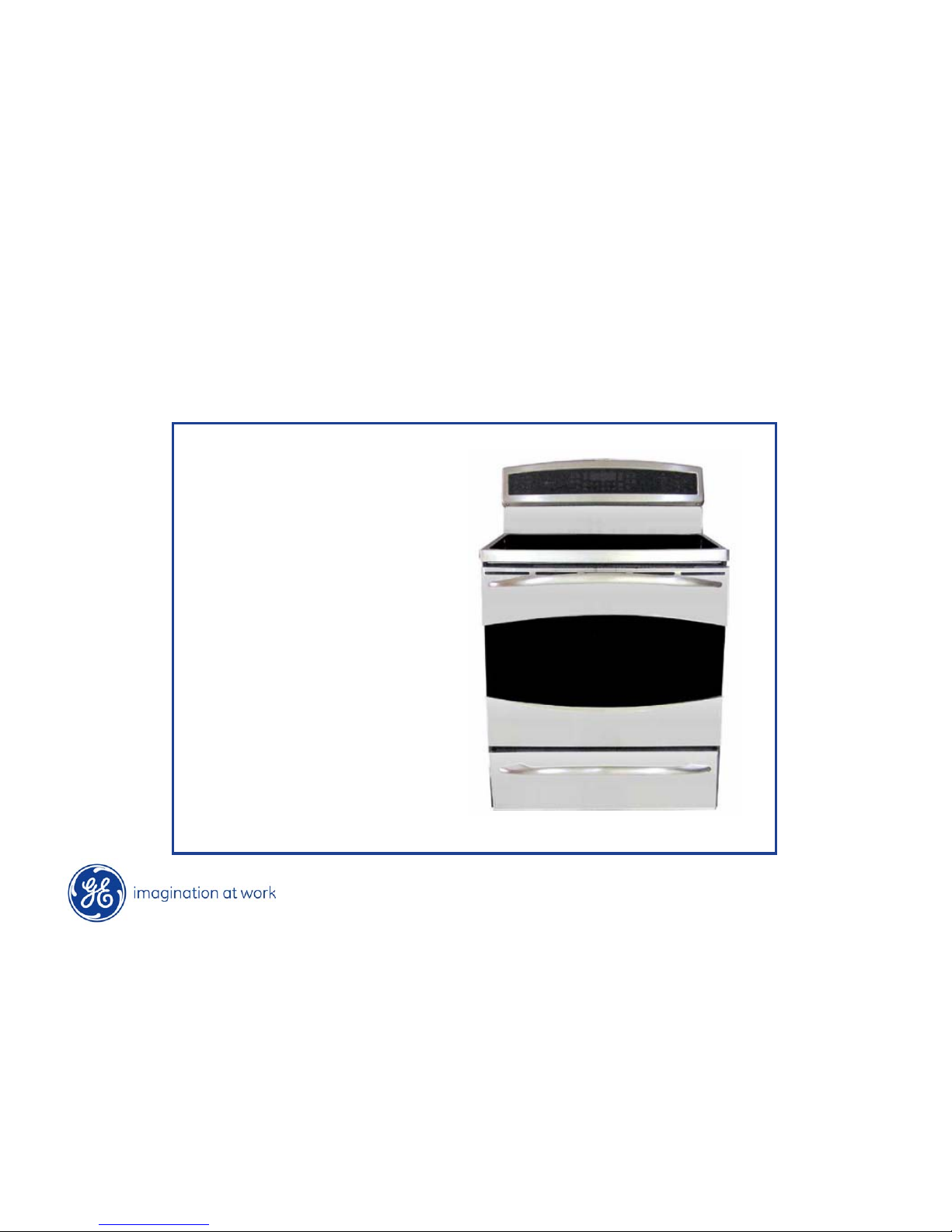
GE Profile Induction Range
Range Models:
PHB925SP1SS
PHB925SP1BB
PHB925SP1WW
Production start FW21
Copyright 2009
Page 2
Copyright 2009
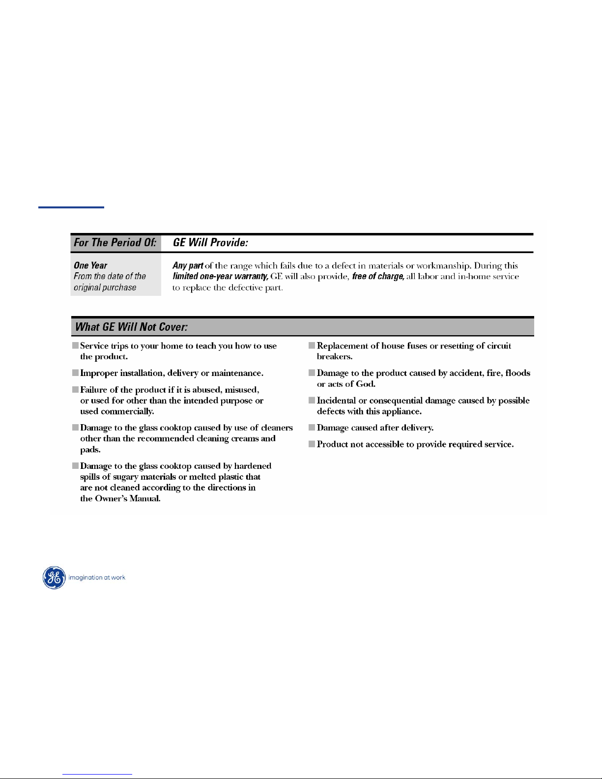
Warranty
Page 3
Copyright 2009
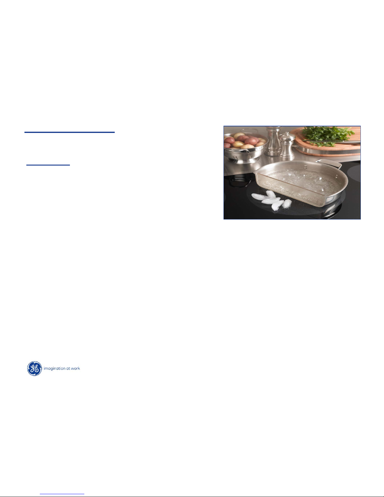
Induction Summary
The new Profile Induction freestanding range has:
•Innovative technology – delivers the responsiveness of gas cooking
•Superior performance – Induction technology heats only the pan and its contents
•Remarkable versatility – This induction cooktop offers the choice of 19 different
power levels, including a 3700-watt, 11 inch element for larger cookware (the highest
wattage induction element in the industry with warming capability, and a low-heat
simmer setting for delicate cooking
•Cooler cooktop surface – Since there is not a traditional thermal heating element,
the induction cooktop stays cooler than conventional radiant cooktop
Induction – A “game changing” technology
for cooking with many features valued by
consumers
Page 4
Copyright 2009
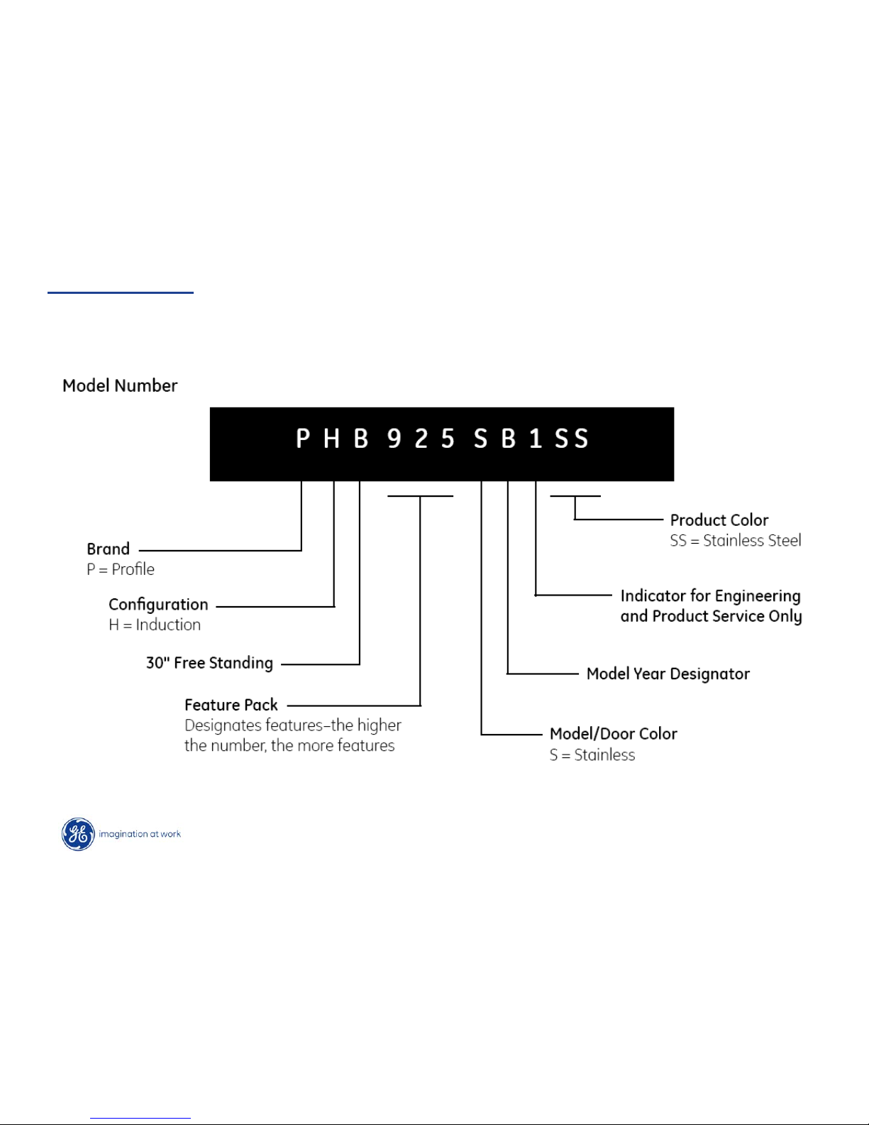
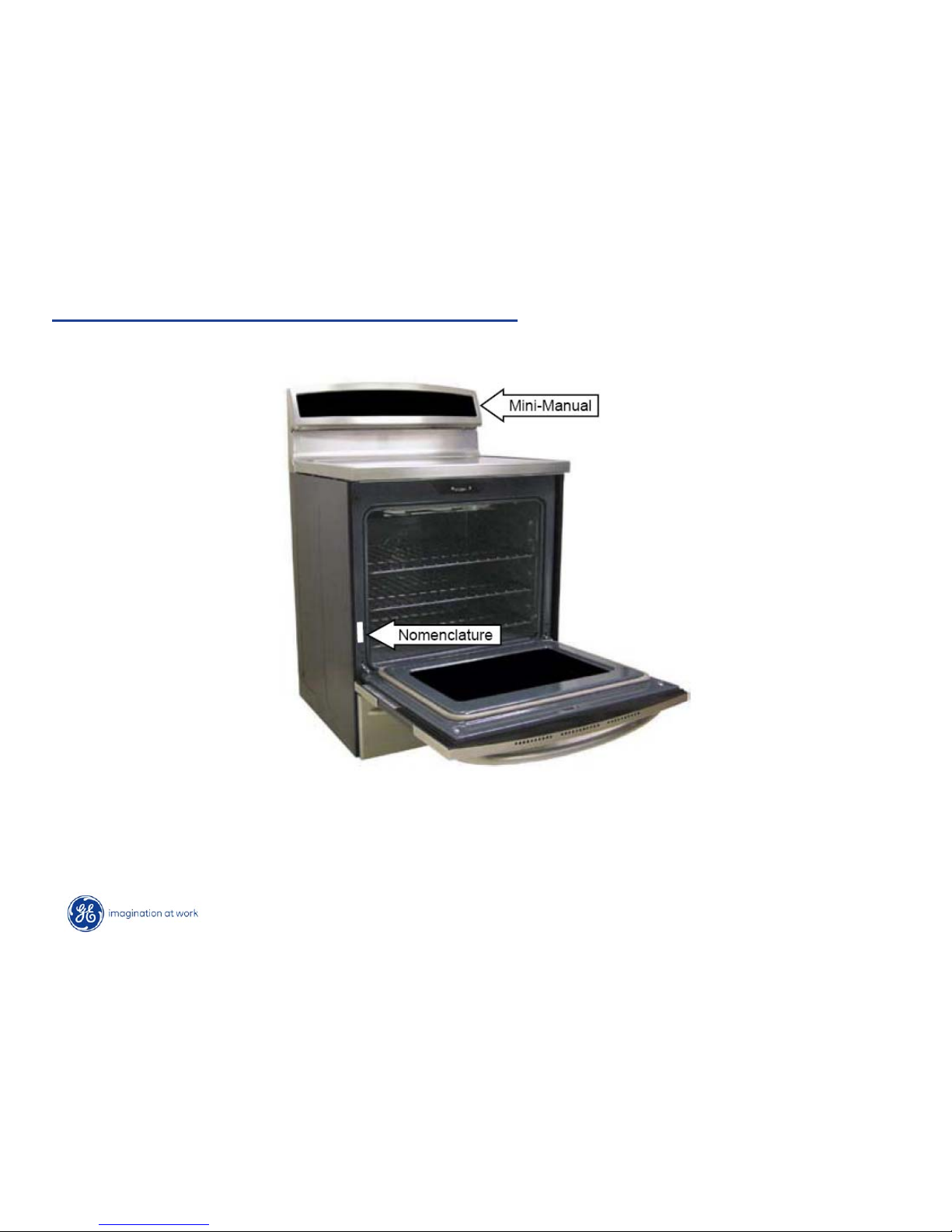
Nomenclature
Page 5
Copyright 2009
Mini Manual & Model/Serial Tag Location
* Mini-Manual is in an envelope and located inside the control panel
Page 6
Copyright 2009
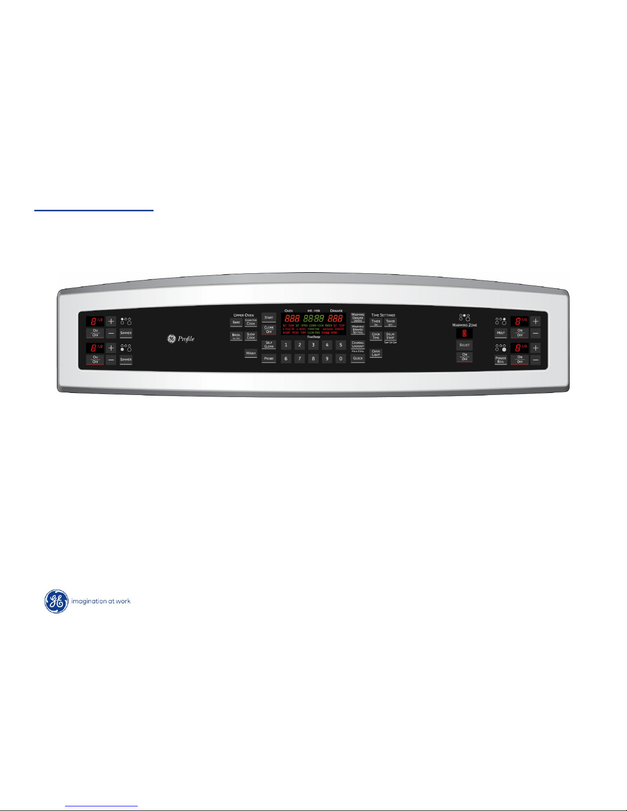
NOTE: bAd LinE in display is to signal a
terminal block cord miswire and will
appear if 120VAC is not present between J215(N) and J20-3 (L2). It will also appear if
there is less than 200VAC between J20-1 (L1)
and J20-3 (L2).
bAd LinE
Voltage Monitor
Page 7
Copyright 2009
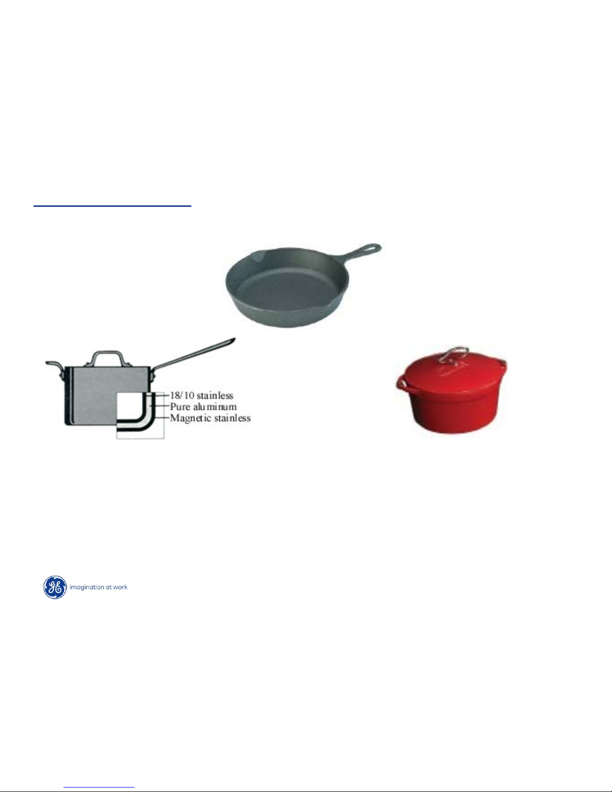
Cookware that Works
One layer must be of magnetic, metal material.
Cast Iron
Clad Cookware
Lodge Ware –- enameled cast iron
To test cookware - use a magnet if a magnet clings to the base of the cookware
it is induction ready.
Consumer can use a refrigerator magnet to verify.
Page 8
Copyright 2009
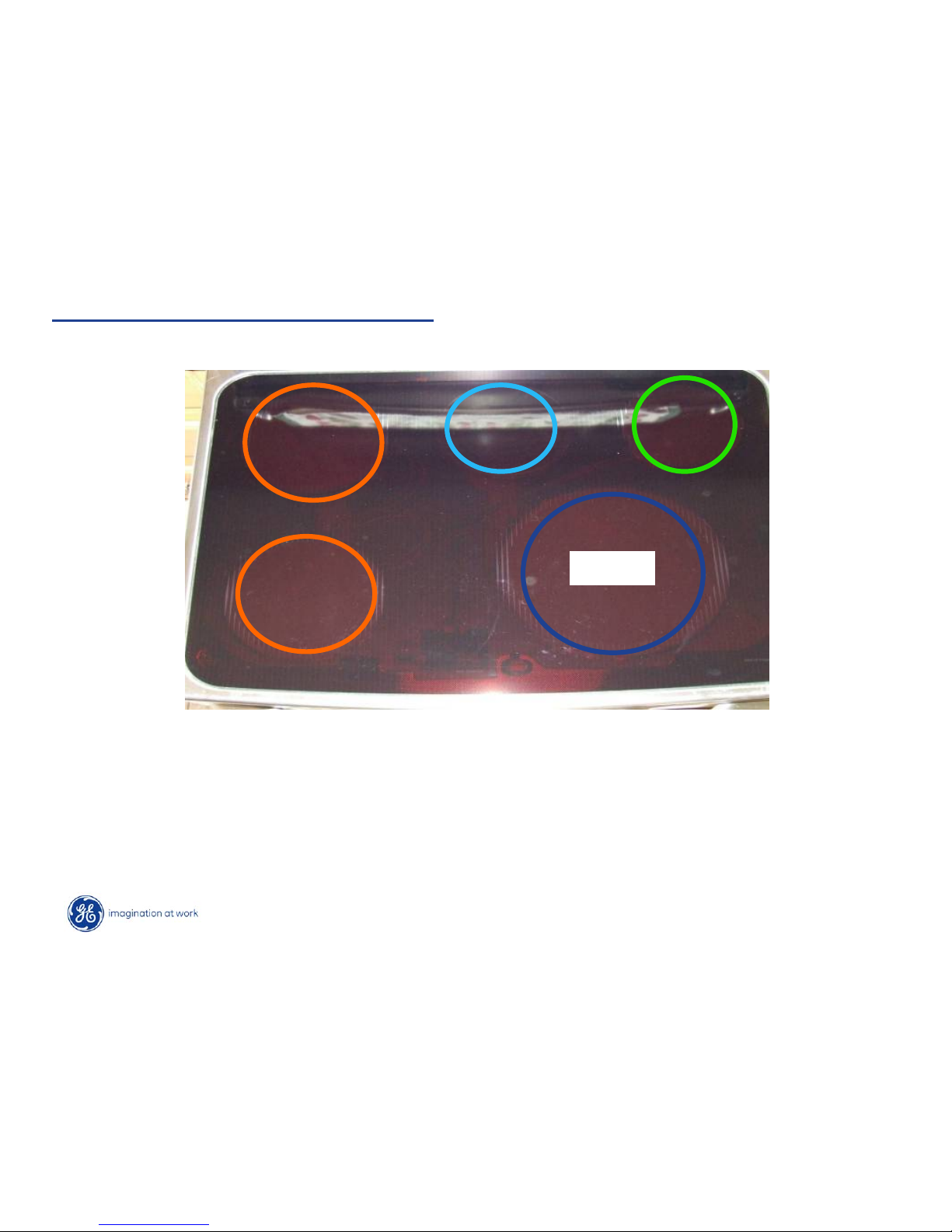
Cooktop Induction Specifications
• (1) 11”- 3700W Induction element
• (2) 7” - 2500W Induction element
• (1) 6” - 1800W Induction element
•(1) 240V 100W Warming element
All Units Have:
3700W
1800W
2500W
2500W
240V
100W
Page 9
Copyright 2009
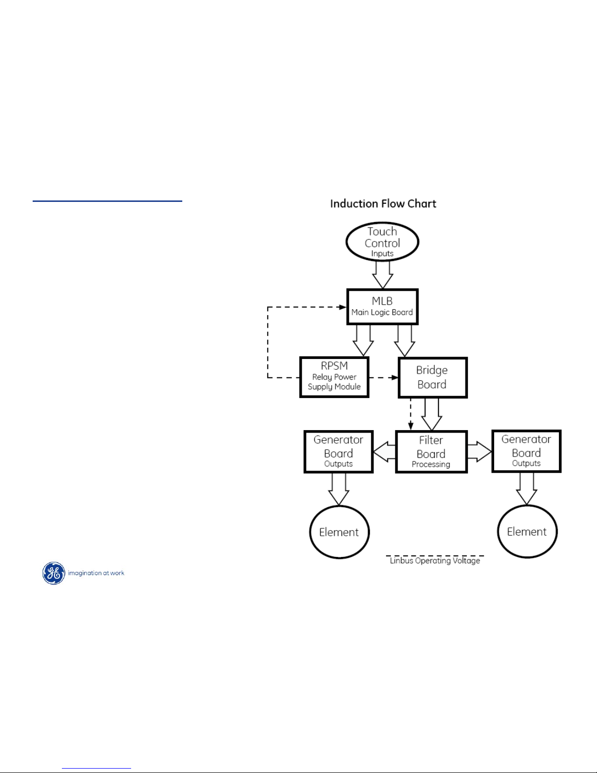
Induction Flow Chart
There are four induction cooktop coils.
The controls for the cooktop module
consist of two burner Touch Boards
connected to and working through the
main logic board. The main logic board is
connected via the LINbus serial wire to
the cooktop module, bridge board and the
RPSM. (Relay Power Supply Module)
located on the back of the range.
The bridge board contains the surface on/
hot cooktop indicator lights. The induction
module cooling fan connection is also
located on this board. The bridge board
bridges the Linbus connections from the
filter board, main logic board along with
the RPSM.
A Fifth cooktop element is a resistive
warmer controlled by the RPSM relays.
See wiring diagrams. No relay boards or
line voltages are brought to the control
panel.
Page 10
Copyright 2009
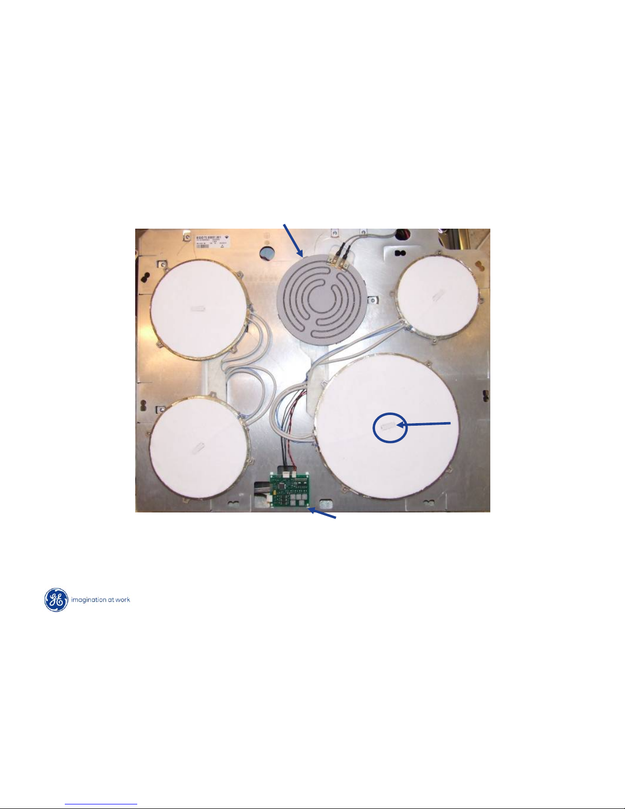
Induction Module
3700W
<1Ω
1800W
<1Ω
2500W
<1Ω
2500W
<1Ω
Bridge Board
240VAC 100W Warming Element Approx 550Ω
Sensor
11”
6”
7”
7”
Page 11
Copyright 2009
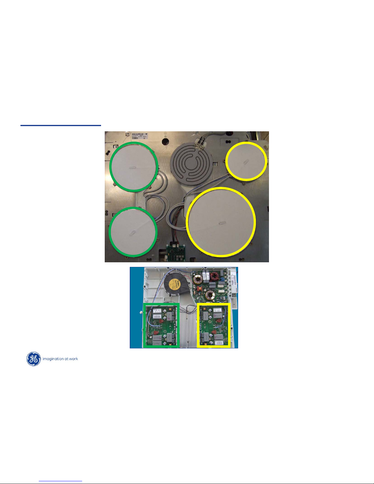
Element Operation
Right generator board
controls right 2 elements.
Left generator board
controls left 2 elements.
Page 12
Copyright 2009
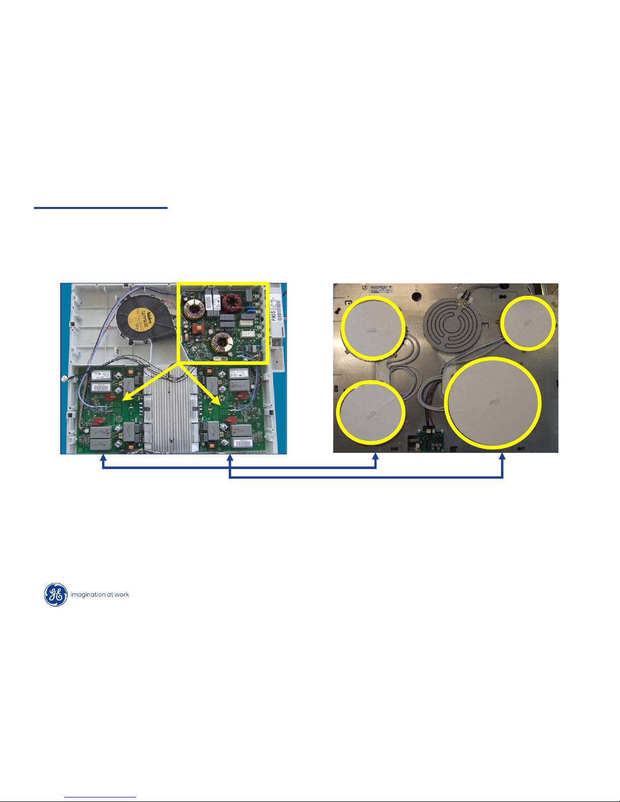
Element Operation
Filter board controls both left and right generator boards.
Page 13
Copyright 2009
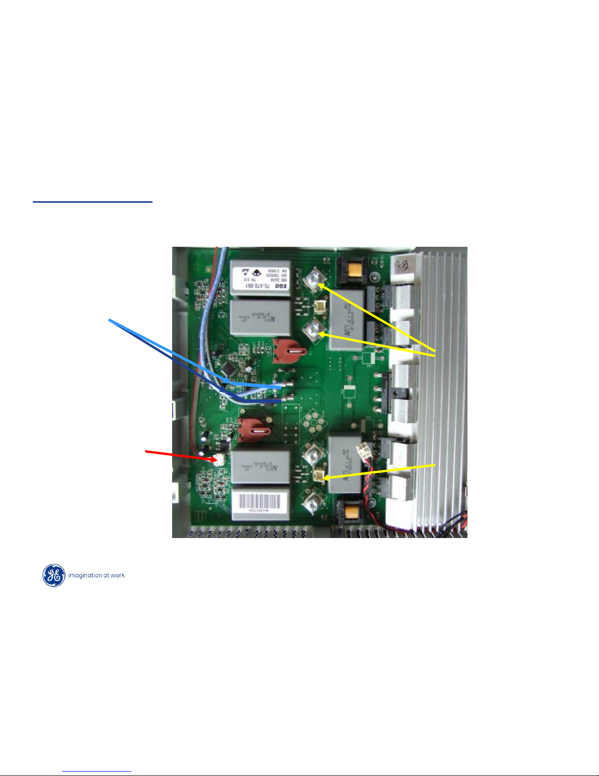
Generator Board
Element Connections
Sensor Connections
L1 & L2 from filter
board
LIN Bus from filter
board (need tool to
remove).
Page 14
Copyright 2009
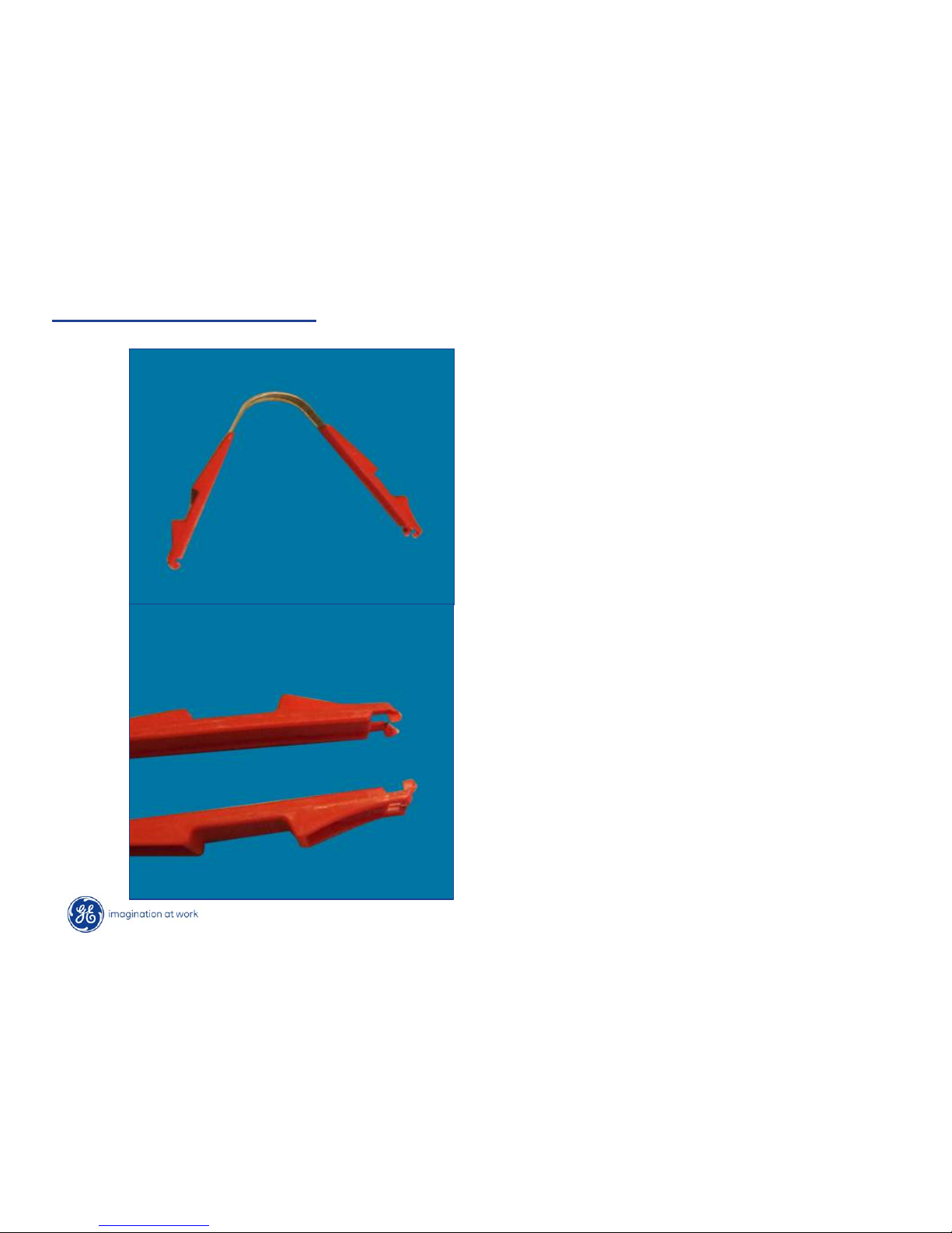
LIN* Bus Removal Tool
Tool supplied with any part that requires
LIN bus removal.
Keep for future use.
* Local Interconnect Network
Page 15
Copyright 2009
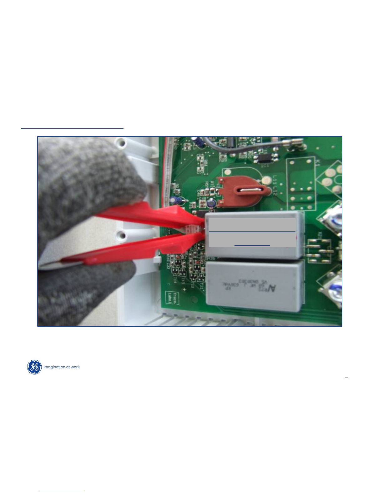
LIN Bus Removal Tool
Generator Board
Relays
• As viewed from this angle, grab the connector in this manner to avoid potential
damage.
Page 16
Copyright 2009
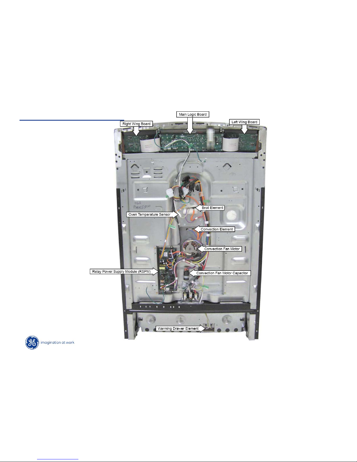
Rear Component Layout
Page 17
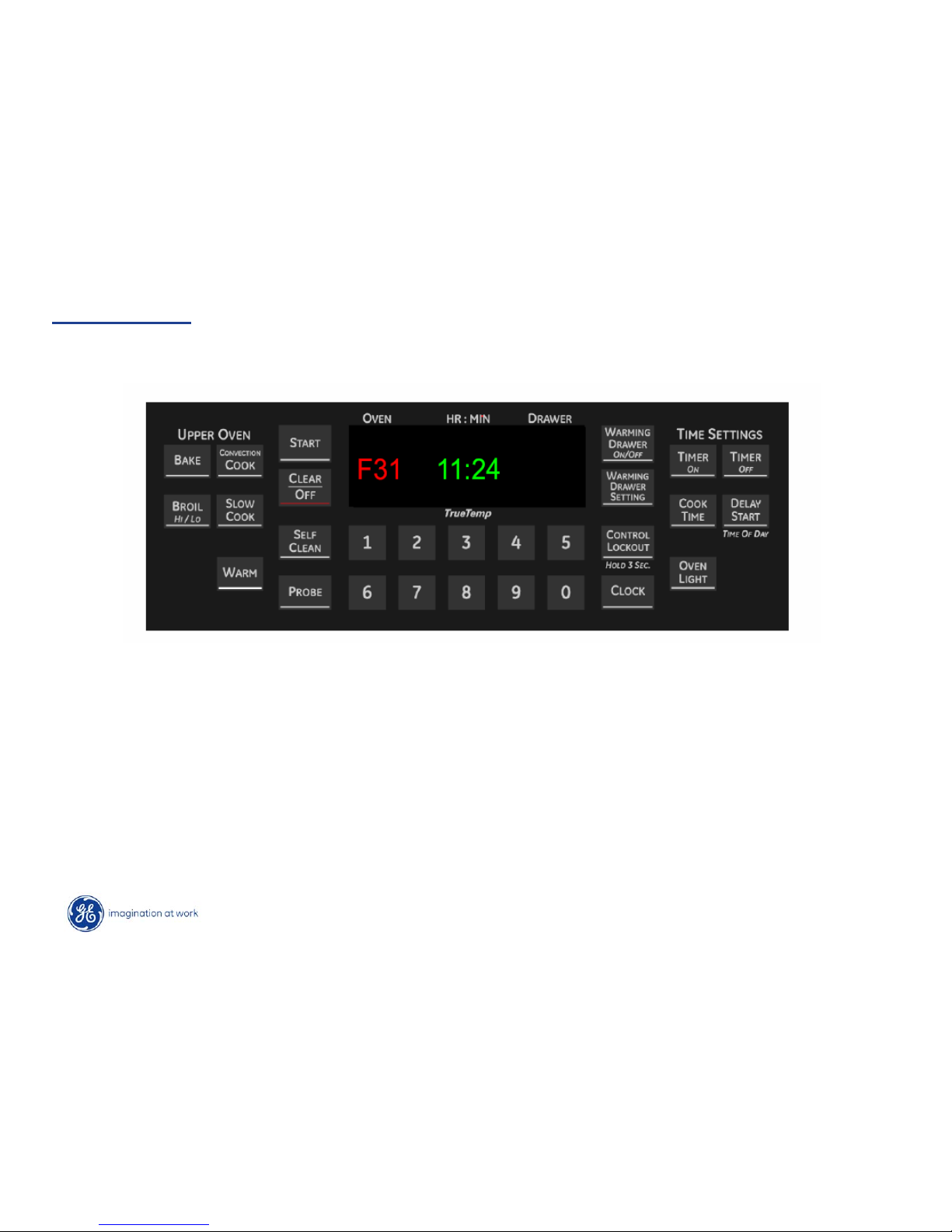
Copyright 2009
For the first three minutes after power up, the F-codes will show on the
display.
Main Logic Failure Codes:
The main logic board has error (F) codes that can be utilized by the service
technician. The error codes are not shown on the display when they occur.
They are stored in EEprom and can be retrieved.
Error Codes
Page 18
Copyright 2009
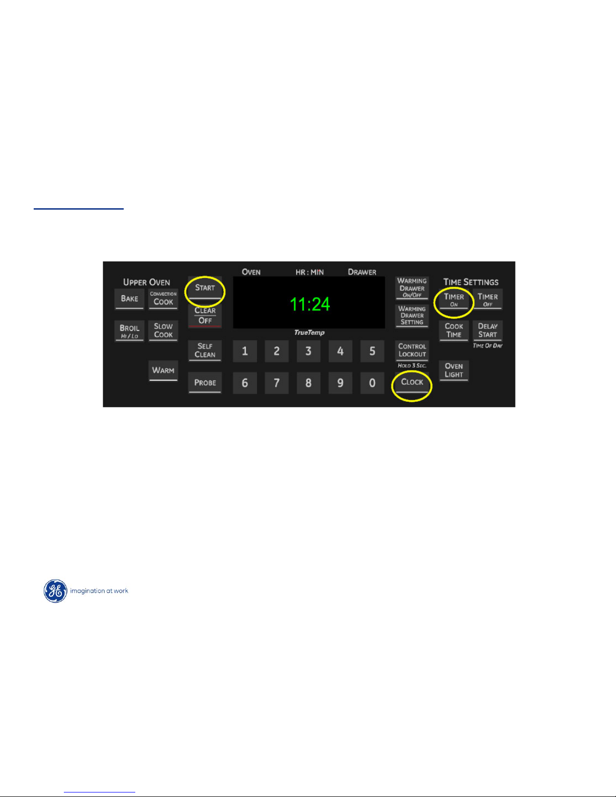
• F-Codes are not shown on the display when they occur.
• They are stored in eeprom and can be retrieved by pressing:
TIMER ON + CLOCK + START
Error Codes
Page 19
Copyright 2009
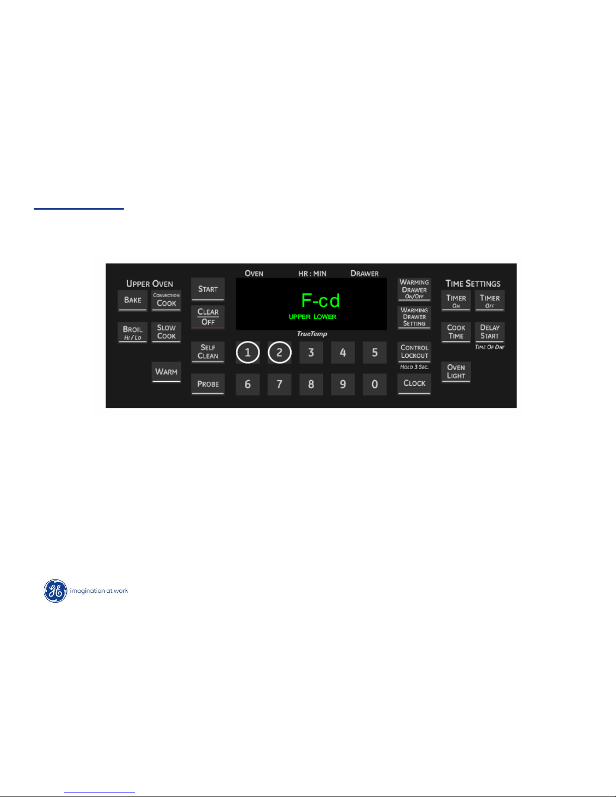
The display then shows F-cd and prompts for an upper or
lower selection. Press 1 for the oven.
Error Codes
Page 20
Copyright 2009
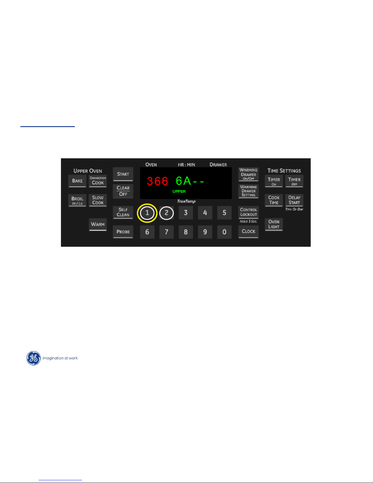
After selecting 1 for the oven, the log is shown.
Error Codes
Page 21
Copyright 2009
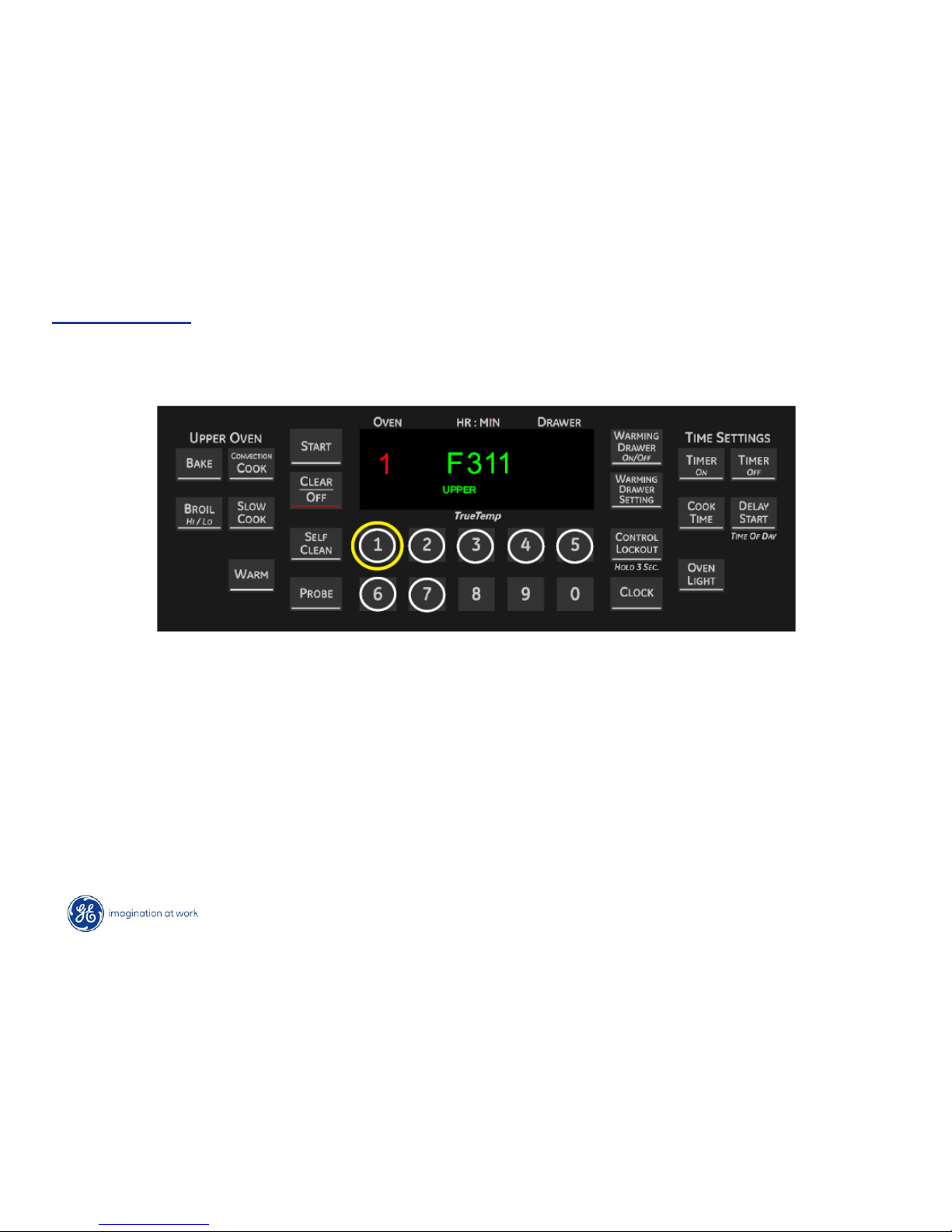
Details of any one of up to 7 stored codes can be recalled
by pressing a numbered key.
Error Codes
Page 22
Copyright 2009
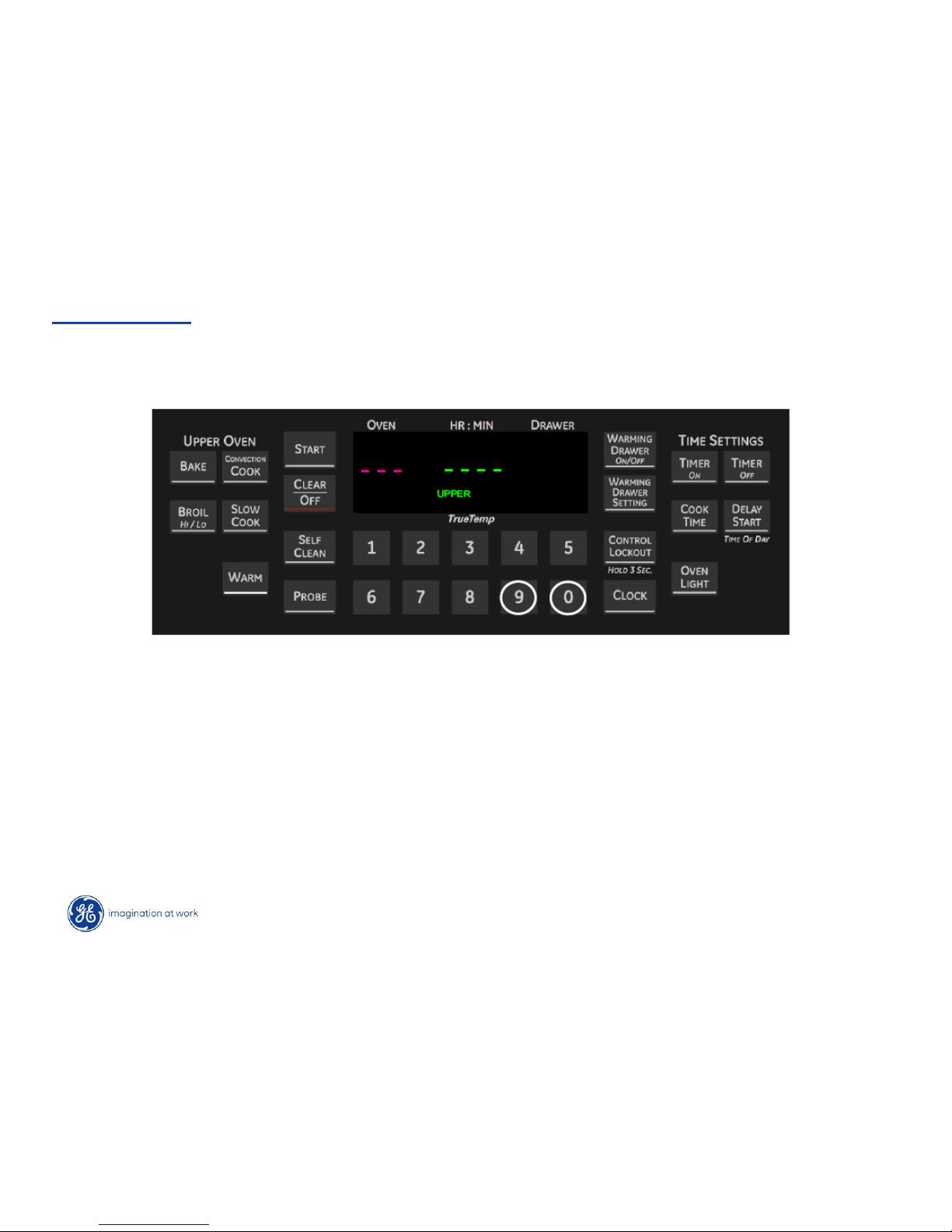
The F-Code log can be erased by pressing 9 and 0 together
while the log is being displayed.
NOTE: Only the log displayed is erased / cleared.
Error Codes
Page 23
Copyright 2009
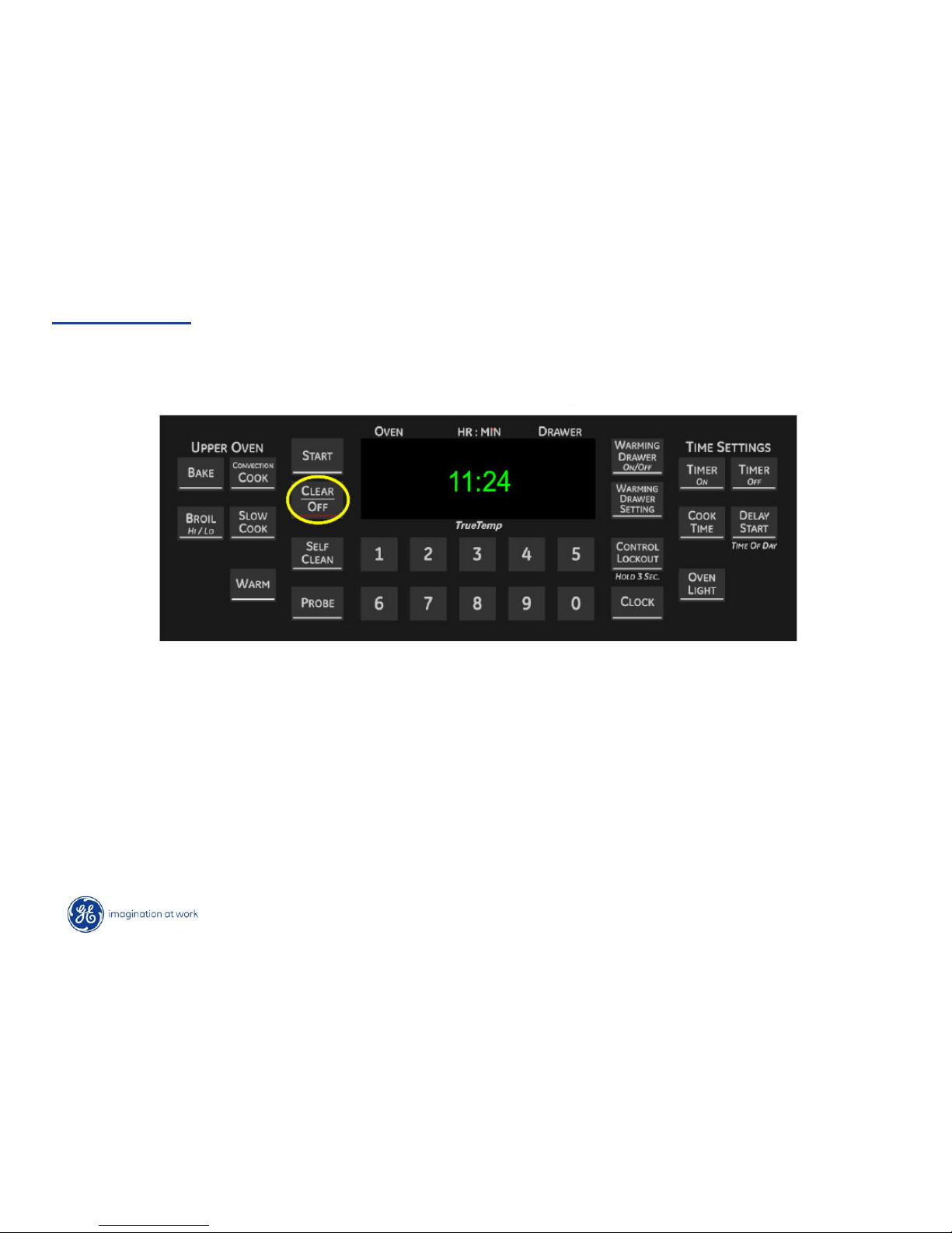
Press CLEAR/OFF to exit the F-Code mode and return to the
time of day display.
Error Codes
Page 24
Copyright 2009
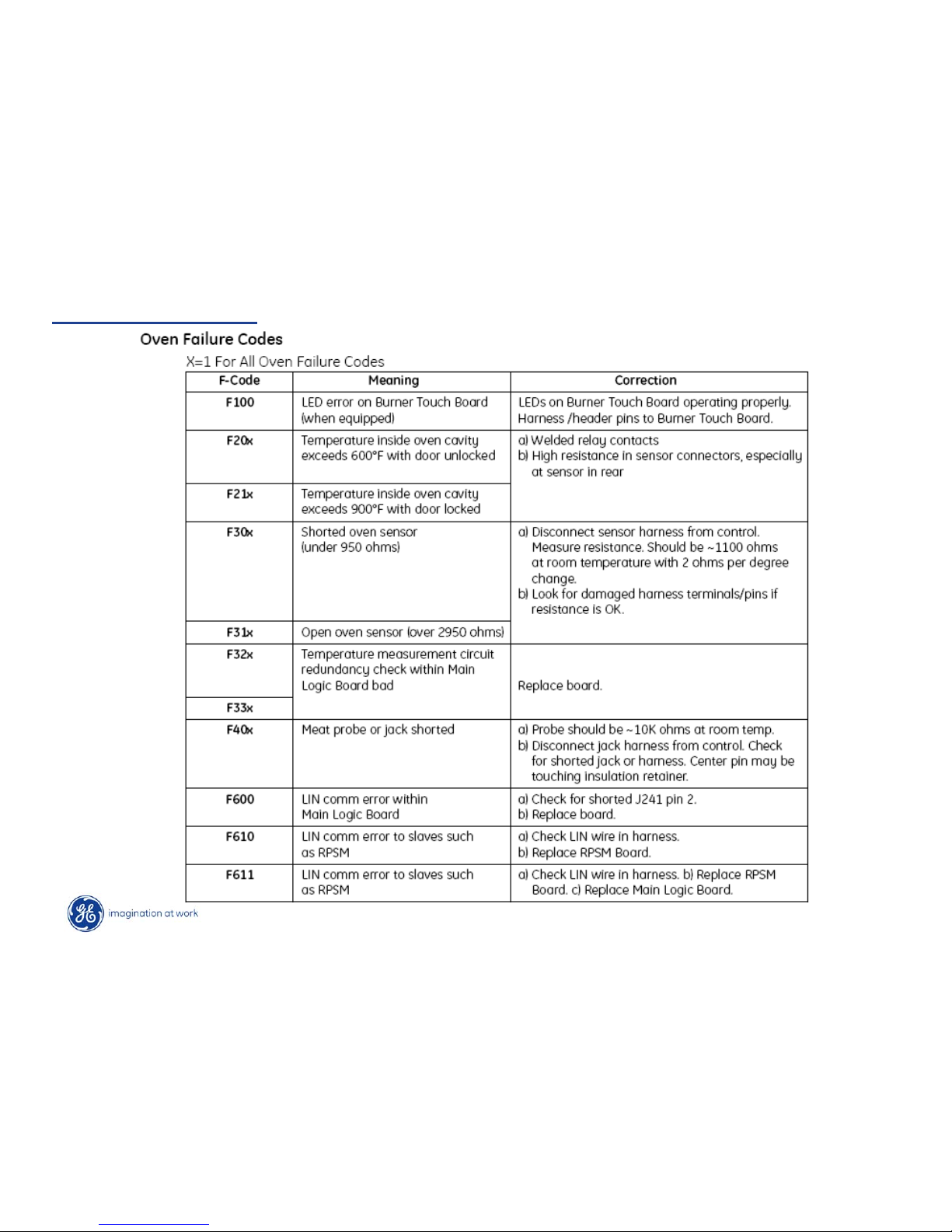
Oven Error Codes
Page 25
Copyright 2009
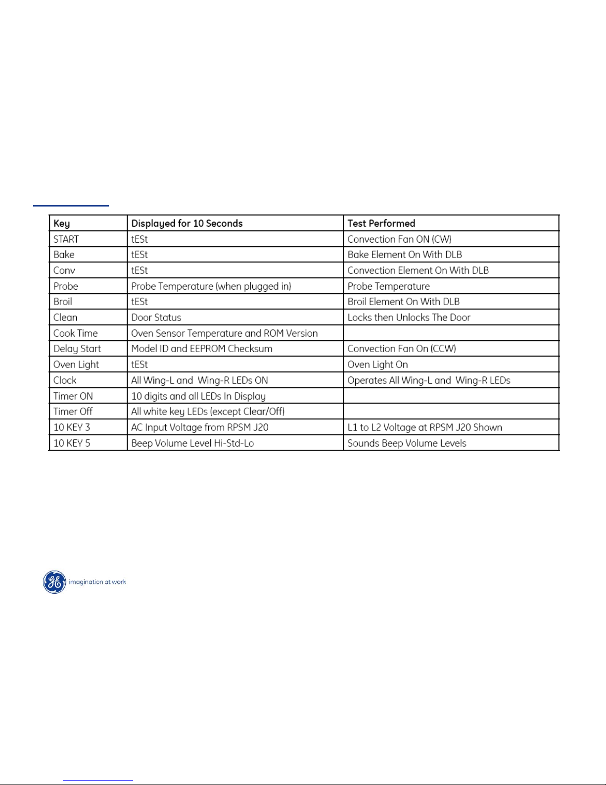
•The entry to Test Mode is available for 3 minutes after power up by pressing together
the 1 & 5 keys.
•The display will switch to tEST.
•Clear/off exits the Test Mode.
•When a test feature is selected, it remains for 10 seconds then returns to tESTStandby.
Test Mode
Page 26
Copyright 2009
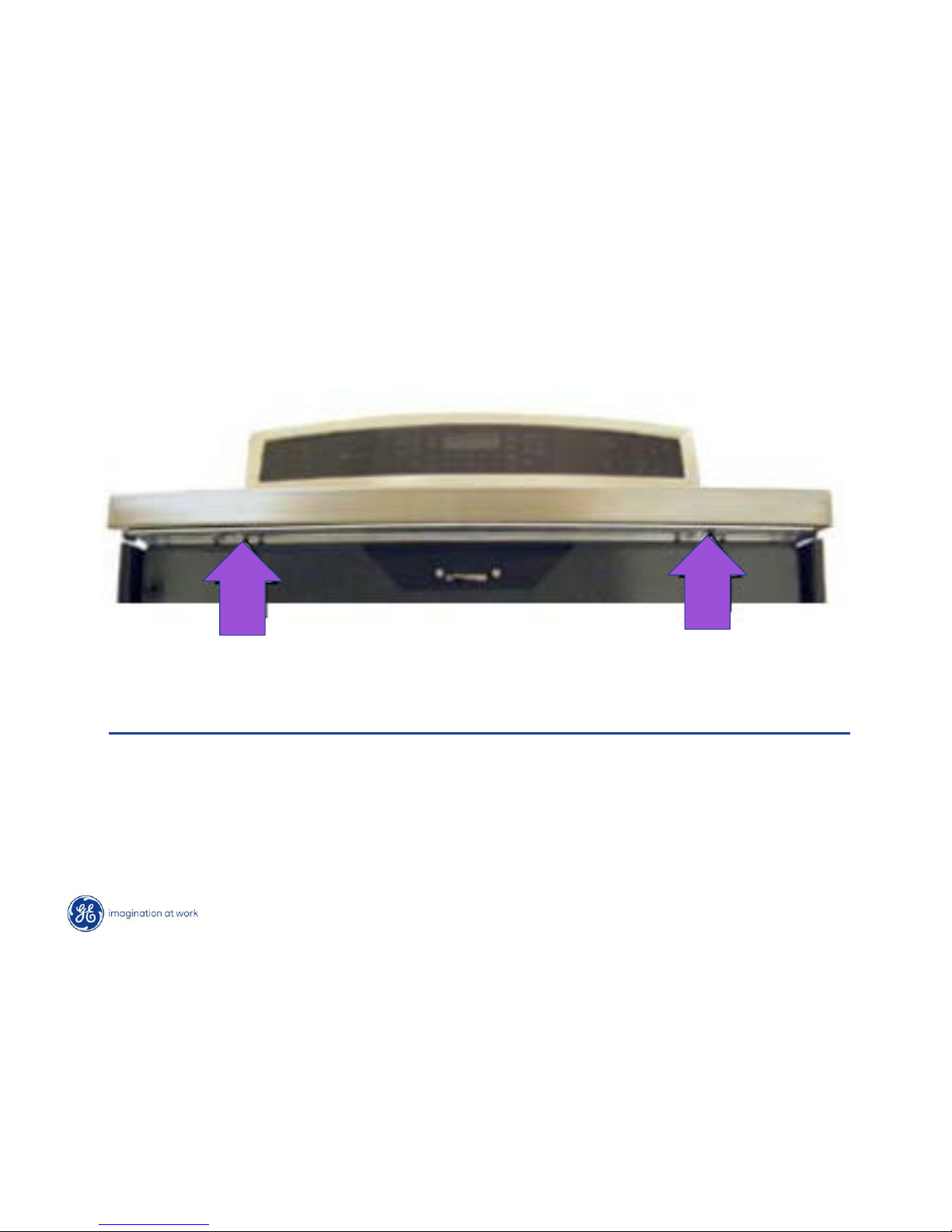
Cooktop Removal
Cooktop frame and ceramic glass come as a complete assembly.
• Remove power.
• Open the oven door.
• Remove (2) ¼” hex head screws which secure the cooktop
to the front oven frame.
Page 27
Copyright 2009
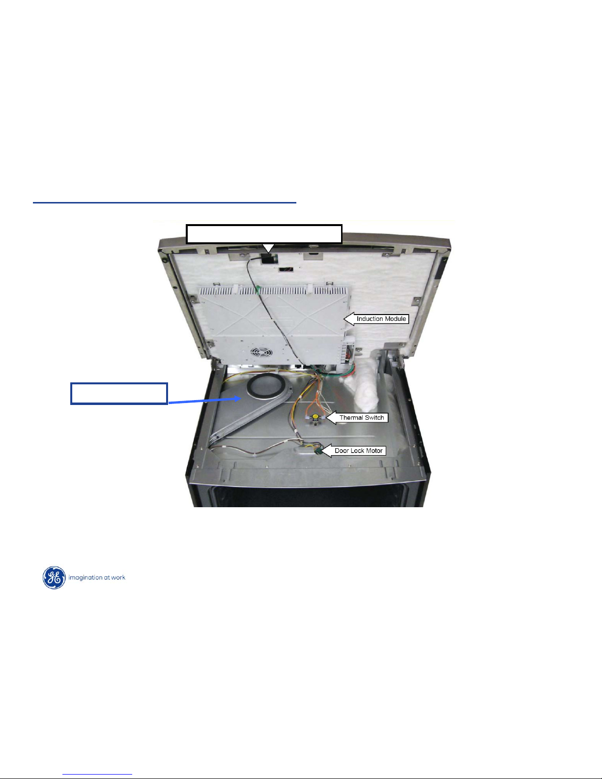
Hot Surface light (Bridge Board)
Module Inlet Vent
Replacing The Hidden Bake Element
Raise or Remove cooktop
Page 28
Copyright 2009
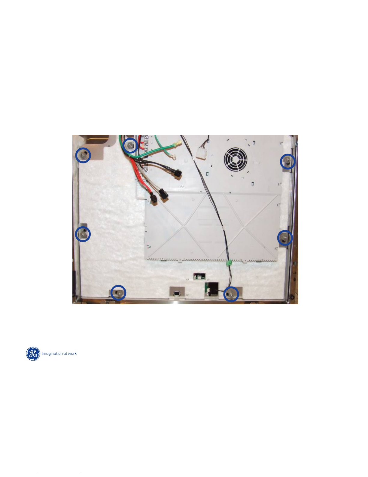
Induction Module
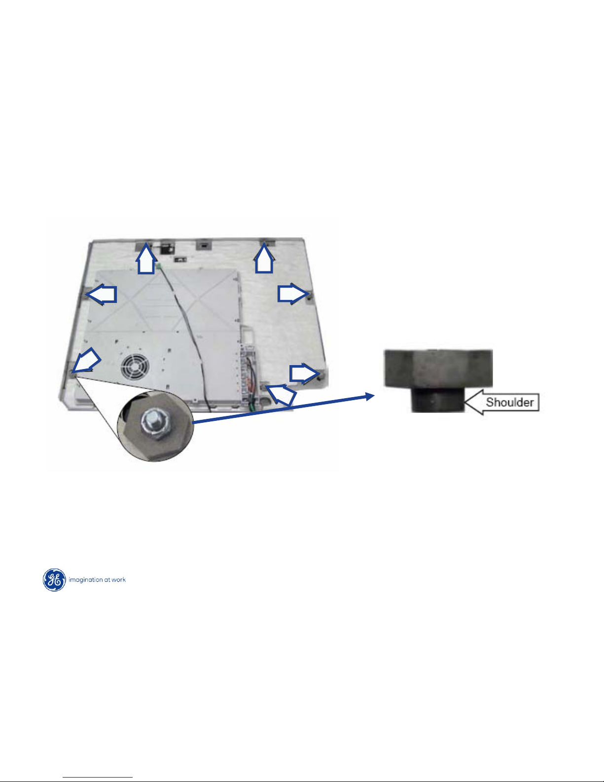
To remove the induction module from the glass cooktop:
Lay cooktop on protective surface and remove the 7 3/8” carriage bolts
Page 29
Copyright 2009
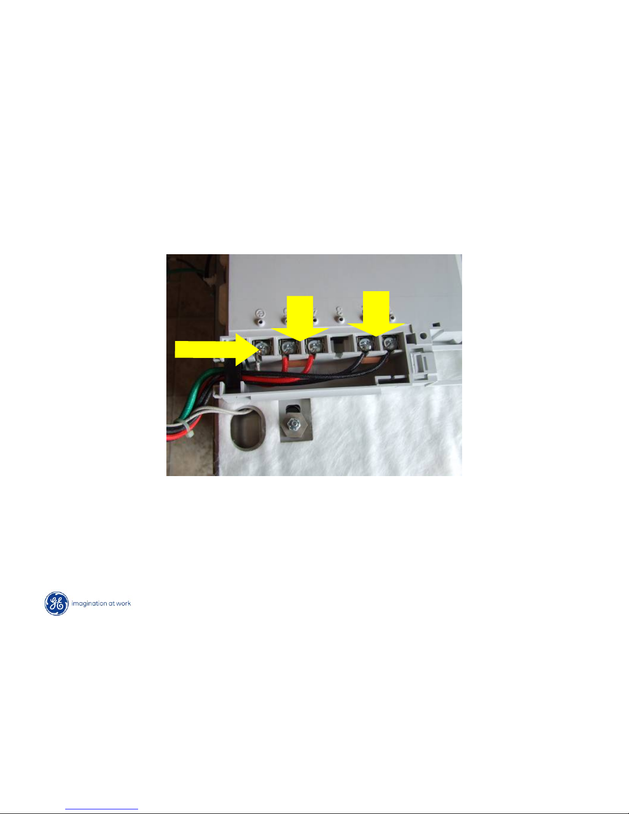
L2
L1
Ground
Module Wiring Connections
Wiring connections to filter board
Note: Jumper blades will fall free when screws are removed.
Make note of location for proper reassembly.
Page 30
Copyright 2009
Induction Module
After removing the 3/8 nut from the carriage bolt you will need to remove the spacer to
release the carriage bolt. Note the shoulder on the spacer mount into the opening on
the cooktop. This allows proper alignment upon reassembly.
Page 31
Copyright 2009
Induction Module
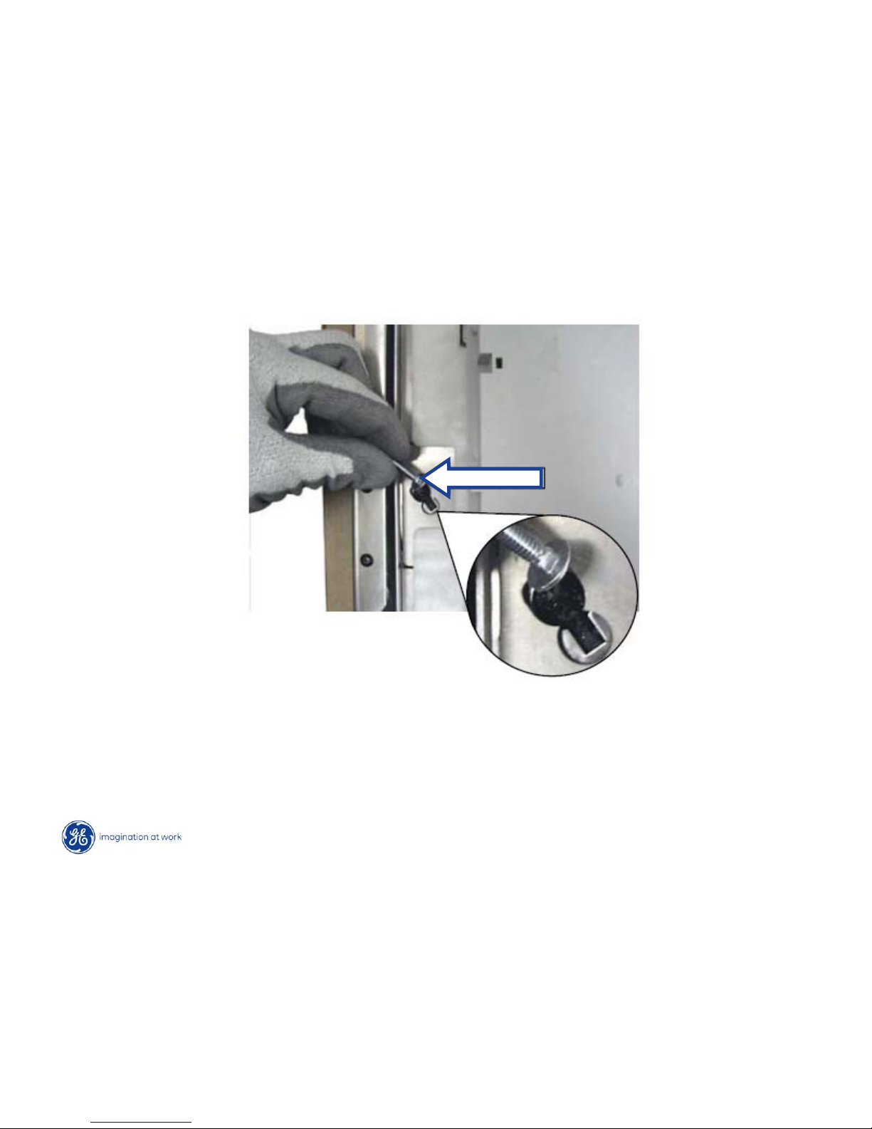
The carriage bolt must then removed by sliding from the square opening to
the rounded opening. Repeat this procedure for all 7 bolts.
Carriage Bolt
Page 32
Copyright 2009
Induction Module
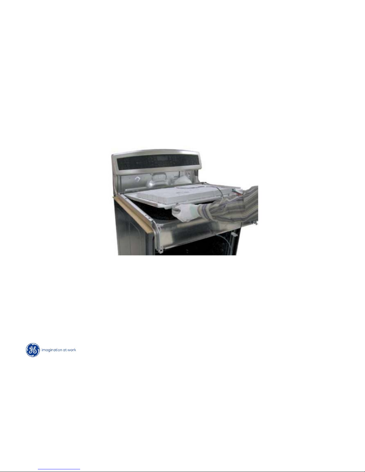
The induction module can now be gently removed from the cooktop
Page 33
Copyright 2009
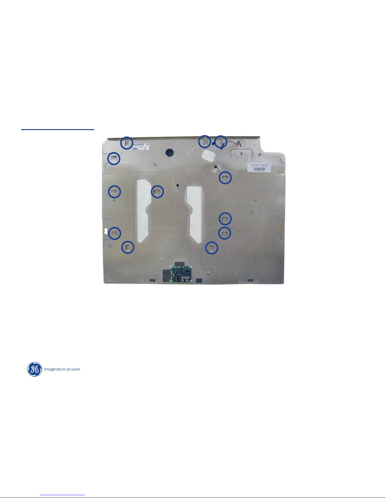
Aluminum Plate
To gain access inside of the induction module:
•Remove all elements
•Disconnect bridge board wiring
•Remove the 12 Phillips screws securing the aluminum plate to the induction module
 Loading...