

GE Profile PHB925SB1SS Technical Service Manual
GE Consumer & Industrial
Technical Service Guide
May 2009
Profi le 30-in.
Free Standing
Induction Range
PHB925SB1SS
31-9186
GE Appliances
General Electric Company
Louisville, Kentucky 40225

IMPORTANT SAFETY NOTICE
!
The information in this service guide is intended for use by
individuals possessing adequate backgrounds of electrical,
electronic, and mechanical experience. Any attempt to repair a
major ap pli ance may result in personal injury and property
damage. The man u fac tur er or seller cannot be responsible for the
in ter pre ta tion of this in for ma tion, nor can it assume any liability in
connection with its use.
WARNING
To avoid personal injury, disconnect power before servicing
this prod uct. If electrical power is required for diagnosis or test
purposes, disconnect the power immediately after performing the
necessary checks.
RECONNECT ALL GROUNDING DEVICES
If grounding wires, screws, straps, clips, nuts, or washers used to
complete a path to ground are removed for service, they must be
returned to their original position and properly fastened.
GE Consumer & Industrial
Technical Service Guide
Copyright © 2009
All rights reserved. This service guide may not be reproduced in whole or in part
in any form without written permission from the General Electric Company.
– 2 –

Table of Contents
Aluminum Plate ................................................................................................................................................................49
Anti-Tip Bracket .................................................................................................................................................................20
Bake Element ......................................................................................................................................................................40
Bridge Board ...................................................................................................................................................................... 49
Broil Element ....................................................................................................................................................................... 37
Circuit Boards Connector Locator Views ...............................................................................................................26
Component Locator Views ........................................................................................................................................... 21
Control Features ................................................................................................................................................................ 9
Control Panel .....................................................................................................................................................................47
Control Panel Assembly .................................................................................................................................................47
Control Panel Rear Cover .............................................................................................................................................33
Convection Element .........................................................................................................................................................38
Convection Fan Assembly ............................................................................................................................................39
Convection Fan Cover ....................................................................................................................................................38
Cooktop Assembly ..........................................................................................................................................................32
Cooktop Components .................................................................................................................................................... 49
Cooktop Elements ............................................................................................................................................................50
Diagnostics and Service Information ......................................................................................................................56
Door Lock Assembly .......................................................................................................................................................44
Door Switch ........................................................................................................................................................................ 35
Electrical Requirements ................................................................................................................................................. 20
Filter Board ..........................................................................................................................................................................55
Generator Boards ............................................................................................................................................................. 54
Glass Touch Panel ...........................................................................................................................................................48
High Limit Thermostat ....................................................................................................................................................45
Induction Module .............................................................................................................................................................53
Installation ...........................................................................................................................................................................20
Introduction ......................................................................................................................................................................... 4
Introduction to Induction Cooking ............................................................................................................................ 6
LINbus Connectors ........................................................................................................................................................... 52
Main Logic Board .............................................................................................................................................................47
Meat Probe and Outlet ..................................................................................................................................................42
Nomenclature .................................................................................................................................................................... 5
Operation Overview ......................................................................................................................................................... 19
Oven Components ..........................................................................................................................................................36
Oven Door Assembly ......................................................................................................................................................28
Oven Door Hinge Receiver ...........................................................................................................................................35
Oven Light Assembly ...................................................................................................................................................... 43
Oven Sensor and Door Switch Test .......................................................................................................................... 63
Oven Temperature Sensor............................................................................................................................................36
Range Components .........................................................................................................................................................28
Rear Cover Removal .......................................................................................................................................................33
Relay Power Supply Module (RPSM) .......................................................................................................................36
Schematics and Wiring Diagrams ............................................................................................................................ 64
Side Panel Removal ......................................................................................................................................................... 34
Smoke Eliminator/Vent Tube ....................................................................................................................................... 42
Thermal Cut-out ................................................................................................................................................................53
Warming Drawer Assembly ....................................................................................................................................... 32
Warming Drawer Element ............................................................................................................................................46
Warranty .............................................................................................................................................................................. 66
– 3 –
Introduction
The Profi le 30-in. free standing induction range with convection oven and warming drawer features
electronic oven and induction element controls. The induction elements provide unmatched cooking
performance and fl exibility. Induction technology heats only the pan and its contents and offers energy
effi ciency by reducing wasted heat when compared to radiant and gas cooktops.
The Profi le 30-in. free standing induction range has the following new features:
Innovative technology• ―delivers the responsiveness of a gas cooktop.
Superior performance• ―Induction technology heats only the pan and
its contents, providing an incredibly fast boil time.
Remarkable versatility• ―This induction cooktop offers the choice of
19 different power levels, including a 3700-watt, 11" element for large
cookware , warming capability, and a low-heat simmer setting for
delicate sauces.
Cooler cooktop surface• ―Since there is not a traditional thermal
heating element, the induction cooktop stays cooler than conventional
radiant cooktops.
Below cooktop venting• ―that dissipates heat, permitting less depth to
the burner box.
Easy cleanability• ―Cooktop cleaning is easier
since spills and splatters do not burn on the
cooktop.
Electronically controlled oven heating elements•
―Provide precise cooking control with fast
preheating.
Convection mode uses reverse-air convection •
technology―a bidirectional fan that works with a
dedicated third heating element to promote even
heat circulation.
Performance compensation for 208-volt •
installation―boosts power as needed in
multifamily dwellings.
Cooktop locked out during self clean• .
Full-extension, self-cleaning porcelain-coated •
racks―can be left in the oven during the self-
clean cycle.
Hidden oven bake element• ―concealed beneath
the oven fl oor, allows quick and easy ash removal
following the self-clean cycle.
– 4 –
Model Number
Brand
P = Profi le
Nomenclature
P H B 9 2 5 S B 1 S S
Product Color
SS = Stainless Steel
Confi guration
H = Induction
30" Free Standing
Feature Pack
Designates features–the higher
the number, the more features
Indicator for Engineering
and Product Service Only
Model Year Designator
Model/Door Color
S = Stainless
Mini-Manual
Serial Number
The fi rst two numbers of the serial number
identify the month and year of manufacture.
Example: AS123456S = January, 2009
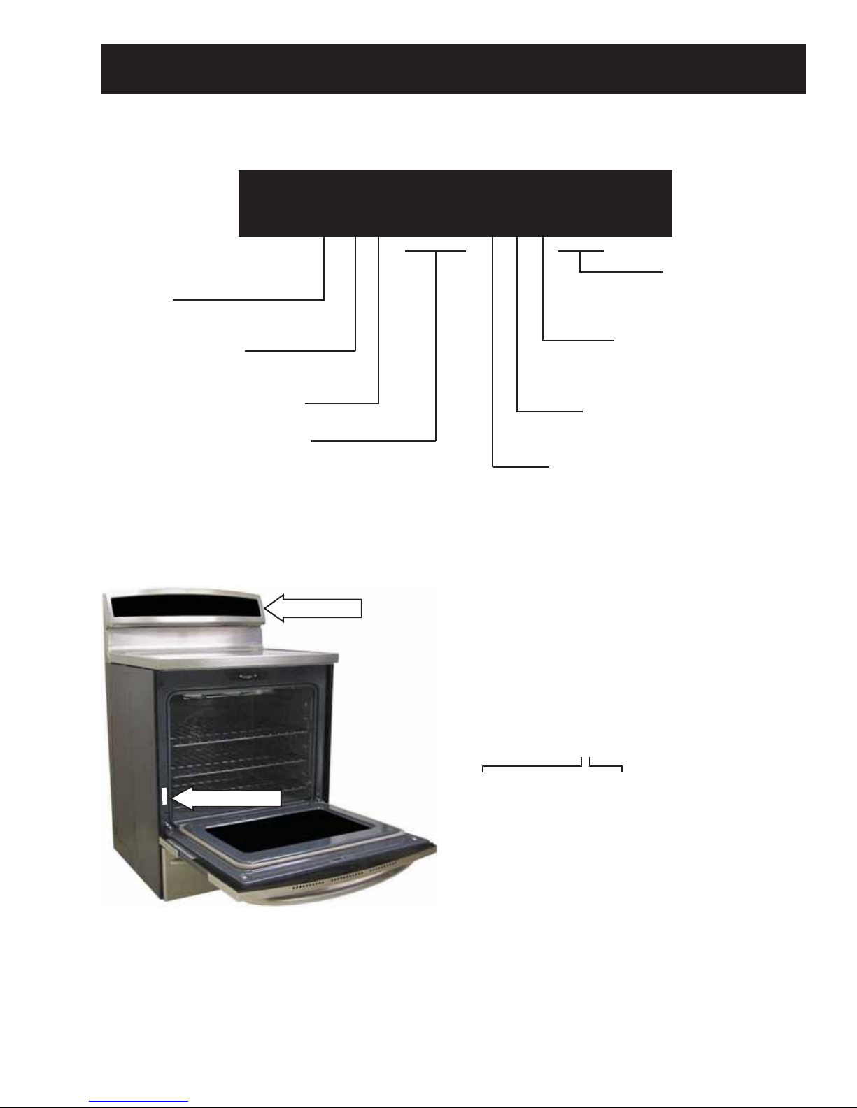
Nomenclature
The nomenclature plate is located on the front
left behind the oven door.
The mini-manual is placed in an envelope
located inside the control panel.
A - JAN 2009 - S
D - FEB 2008 - R
F - MAR 2007 - M
G - APR 2006 - L
H - MAY 2005 - H
L - JUN 2004 - G
M - JUL 2003 - F
R - AUG 2002 - D
S - SEP 2001 - A
T - OCT 2000 - Z
V - NOV 1999 - V
Z - DEC 1998 - T
– 5 –
The letter des ig nat ing
the year re peats every
12 years.
Example:
T - 1974
T - 1986
T - 1998
Introduction to Induction Cooking
How Induction Cooking Works
Induction cooking uses high frequency (20-50 K hz)
magnetic energy to heat a ferrous metal pan when
it is placed over the induction coil. The induction
fi elds have no affect on nonmagnetic surfaces
such as paper, plastic, or nonferrous metals like
aluminum, or copper. Thermal sensors under the
glass surface communicate with microprocessor
controls for pan sensing and turn-down.
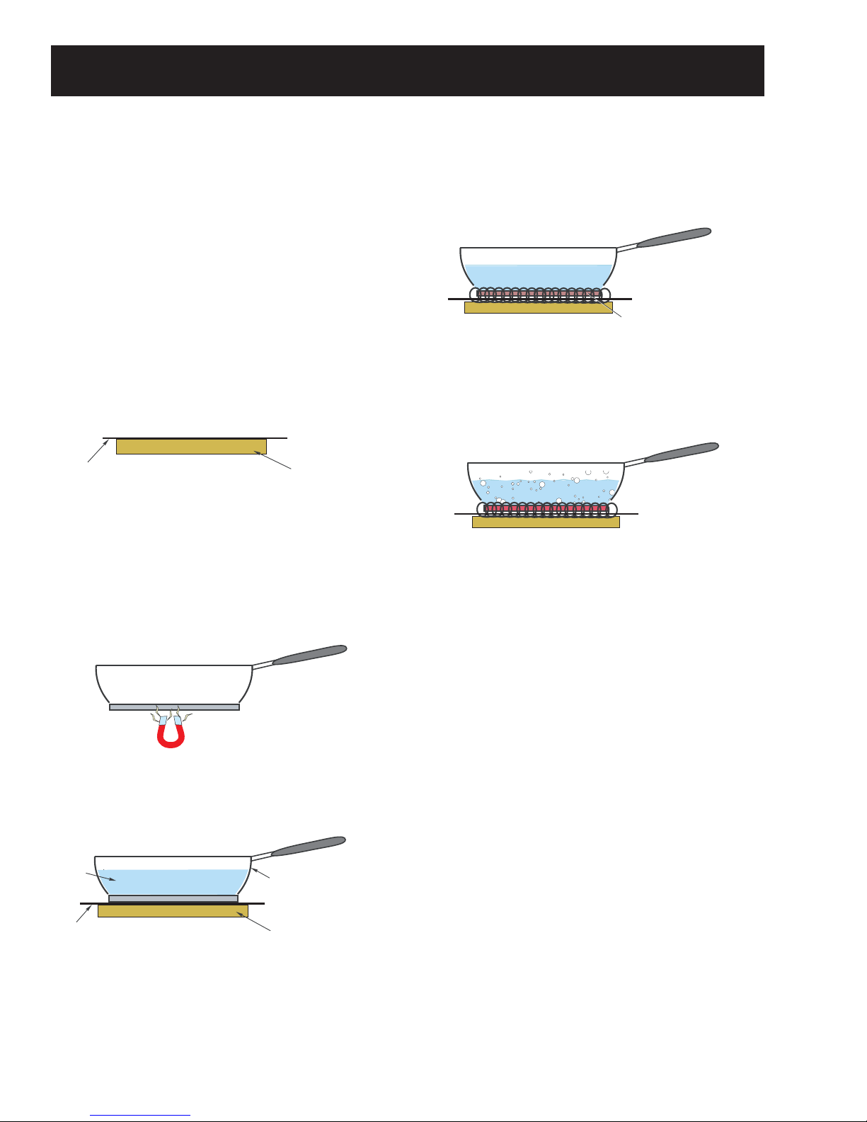
Part one: Coil produces electromagnetic energy
The fi rst component needed is an induction coil or
element. The induction coil generates the magnetic
fi eld needed for induction cooking.
Glass Cooktop Surface
Induction Coil
Part two: Pan uses the energy to produce heat
The second component is the ferromagnetic cooking
pan with a bottom constructed of material that will
attract a magnet. If a magnet will not stick to the
bottom of the pan, it cannot be used for induction
cooking.
Induction cooking is very effi cient. The energy
created by the induction coil is applied to only the
bottom of the pan.
Induction Fields
The contents of the pan are therefore heated more
quickly than they would be if heated by a gas fl ame
or a traditional radiant heating element.
By heating only the bottom of the pan, the
surrounding surface remains cooler than with
traditional cooktops.
Testing Bottom of Pan with Magnet
When the proper type of pan is placed over an
energized induction coil, a fi eld of magnetic waves
will cause the bottom of the pan to heat.
Water
Glass Cooktop Surface
Pan with Bottom of
Magnetic Material
Induction Coil
Features:
Easy cleanability• ―Cooktop cleaning is easier
since spills and splatters do not burn on the
cooktop, which is about 500°F vs 1200°F for
radiant.
Control and responsiveness equal to gas• ―This
induction cooktop gives you instant control of
the amount of heat added to the cookware.
Fast and powerful• ―Provides incredibly fast boil
time. 3700 W, 8.5 min. to boil vs 12 to 14 min. for
radiant and 14 to 16 min. for gas (18k BTU).
Effi cient performance• ―Induction technology
heats only the pan and its contents, not the
kitchen. Effi ciency ratings are: Induction 83%,
Radiant 72%, and Gas 38%.
– 6 –
(Continued next page)
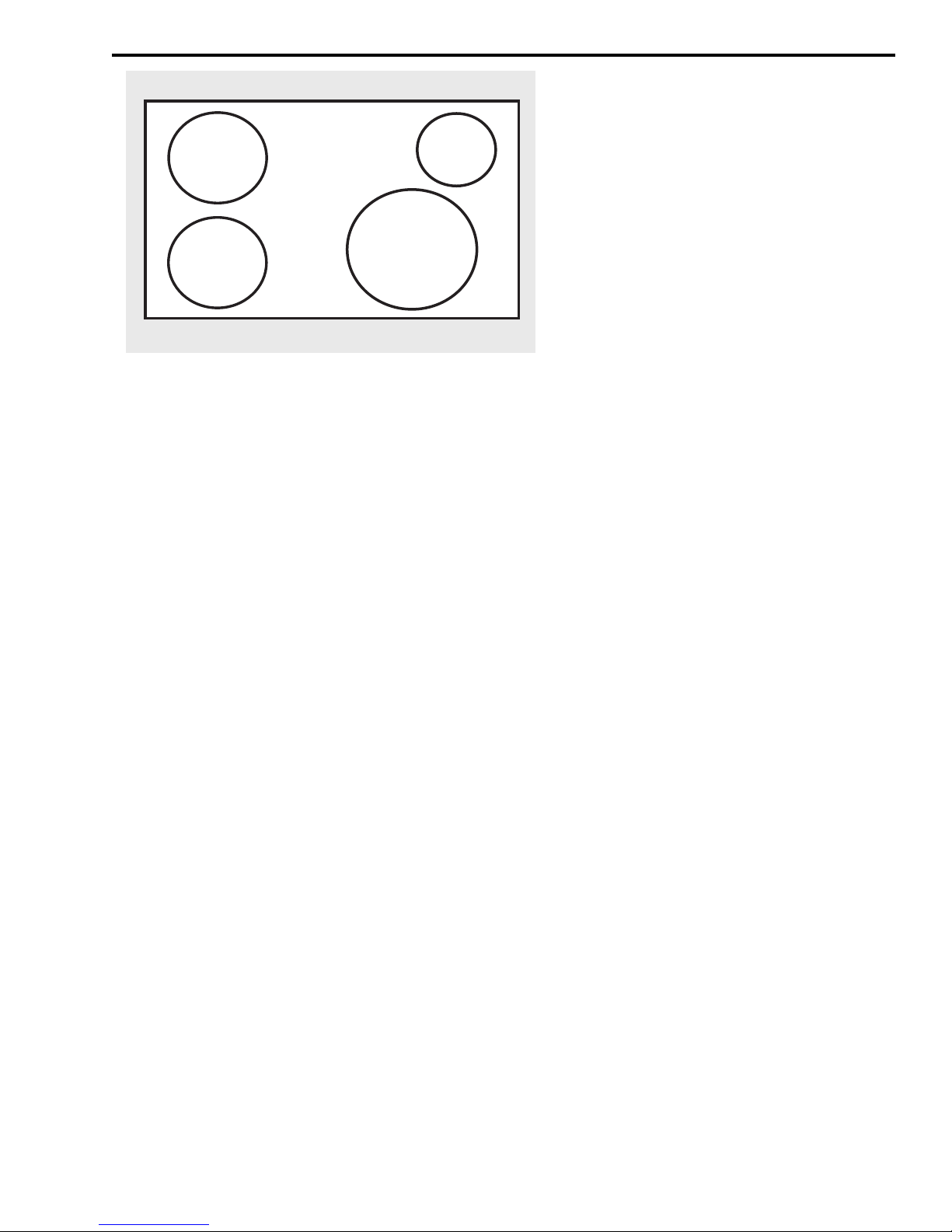
5-3/4” Min. Dia.
5 ¾" Min. Dia.
Pan Size
Pan Size
LR
5 ¾" Min. Dia.
5-3/4” Min. Dia.
Pan Size
Pan Size
LF
4-3/4” Min. Dia.
Pan Size
4 ¾" Min. Dia.
7” Min. Dia.
Pan Size
7" Min. Dia.
Pan Size
RF
Pan Size
RR
Using the correct size cookware
Each cooking element requires a MINIMUM
pan size. If the pan is properly centered, and
of the correct material, but is too small for
the cooking element, the element cannot be
activated. The power level setting displayed
will fl ash for approximately 30 seconds, then
will turn off.
Cookware larger than the element ring may
be used; however, induction heating will only
occur above the element.
For best results, the cookware must make
FULL contact with the glass surface.
Do not allow the bottom of the pan or
cookware to touch the surrounding metal
cooktop trim.
For best performance, match the pan size
to the element size. Using a smaller pot on a
larger burner will generate less power at any
given setting.
– 7 –
(Continued next page)
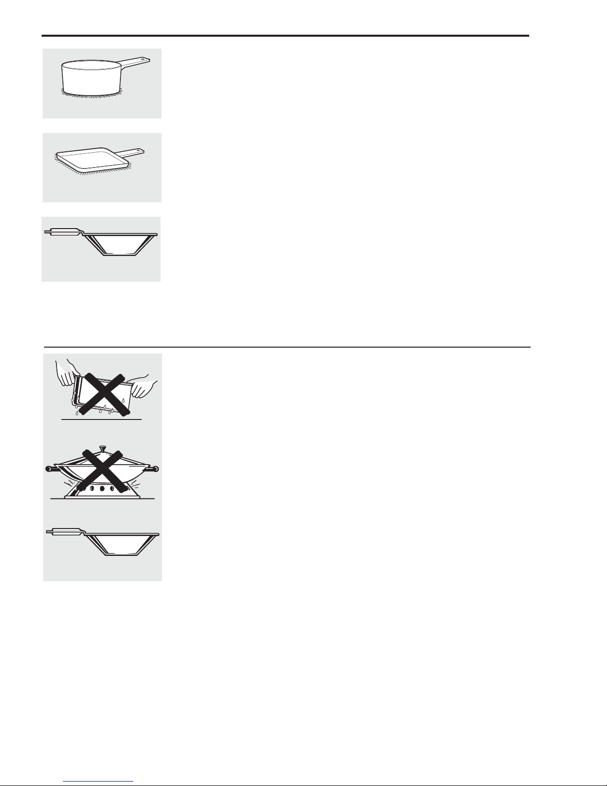
Use flat-bottomed pans.
Use a griddle.
Use a flat-bottomed wok.
Suitable Cookware
Use quality cookware with heavier
bottoms for better heat distribution
and even cooking results. Choose
cookware made of magnetic stainless
steel, enamel coated cast iron,
enameled steel and combinations
of these materials.
Some cookware is specifically
identified by the manufacturer for use
with induction cooktops. Use a magnet
to test if the cookware will work.
Flat-bottomed pans give best results.
Pans with rims or slight ridges can be
used.
Round pans give best results. Pans
with warped or curved bottoms will
not heat evenly.
For wok cooking, use a flat-bottomed
wok. Do not use a wok with a support
ring.
Cookware “noise”
Slight sounds may be produced by
different types of cookware. Heavier
pans such as enameled cast iron
produce less noise than a lighter
weight multi-ply stainless steel pan.
The size of the pan, and the amount
of contents, can also contribute to
the sound level.
When using adjacent elements that are
set at certain power level settings,
magnetic fields may interact and
produce a low whistle or intermitted
"hum". These noises can be reduced or
eliminated by lowering or raising the
power level settings of one or both of
the elements. Pans that completely
cover the element ring will produce less
noise.
A low “humming” noise is normal
particularly on high settings.
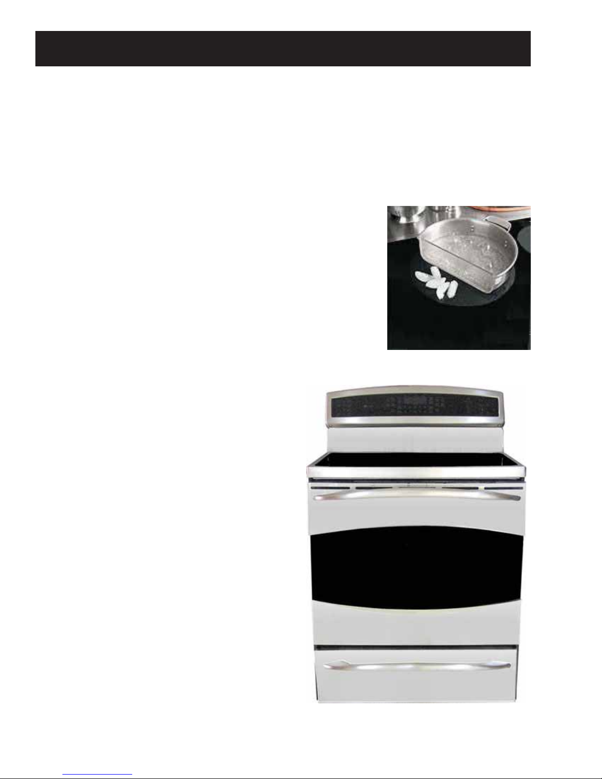
Do not place wet pans
on the glass cooktop.
Do not use woks with support
rings on the glass cooktop.
Use flat-bottomed woks
on the glass cooktop.
For Best Results
■ Do not place wet pans or lids on the
cooking surface or induction rings.
■ Do not place wet fingers on the glass
cooktop. Wipe up spills on the controls
with dry hands.
■ Do not use woks with support rings. This
type of wok will not heat on an induction
element.
■ Use only a flat-bottomed wok, available
from many cookware manufacturers.
The bottom of the wok should match the
diameter of the induction ring to insure
proper contact.
■ Some special cooking procedures
require specific cookware such as
pressure cookers, deep-fat fryers, etc.
Cookware with flat bottoms that match
the size of the surface element being
used will produce the best results.
– 8 –
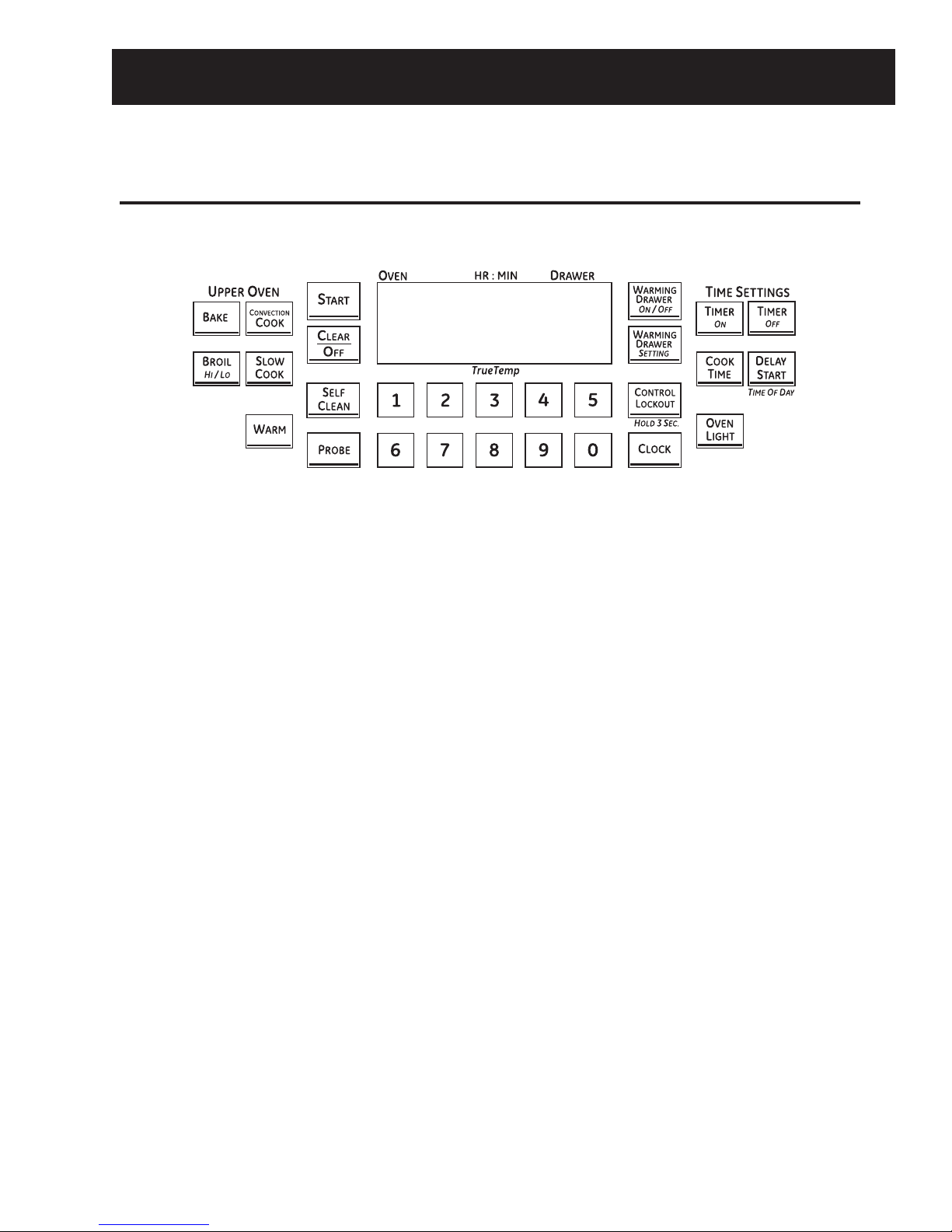
Control Features
Using the oven controls.
Throughout this manual, features and appearance may vary from your model. See the control panel below that
matches your model.
BROIL HI/LO Pad
Touch the BROIL HI/LO pad once for HI Broil.
To change to LO Broil, touch the BROIL HI/LO pad
again.
Touch the START pad.
When broiling is fi nished, touch the CLEAR/OFF pad.
BAKE Pad
Touch the BAKE pad.
Touch the number pads to set the desired oven
temperature.
Touch the START pad.
When baking is fi nished, touch the CLEAR/OFF pad.
CONVECTION COOK Pad
Touch the CONVECTION COOK pad.
Touch the number pads to set the desired oven
temperature.
Touch the START pad.
When cooking is fi nished, touch the CLEAR/OFF pad.
WARM Pad
Touch to keep cooked foods warm.
SLOW COOK Pad
Touch for long hours of unattended cooking.
PROBE Pad
Touch when using the probe to cook food.
SELF CLEAN Pad
Touch to self-clean the oven.
CLEAR/OFF Pad
Touch to cancel ALL oven operations except the
clock and timer.
– 9 –
(Continued next page)

START Pad
Must be touched to start any cooking or cleaning
function.
OVEN LIGHT Pad
Touch to turn the oven lights on or off.
CONTROL LOCKOUT Pad
Your control will allow you to lock out the touch
pads and the cooktop so they cannot be activated
when touched.
To lock the controls and cooktop:
TIMER ON/OFF Pads
Touch to set the kitchen timer.
COOK TIME
Pad
Touch this pad and then touch the number pads to
set the amount of time you want your food to cook.
The oven will shut off when the cooking time has
run out.
DELAY START Pad
Use along with the COOK TIME or SELF CLEAN pads
to set the oven to start and stop automatically at a
time you set.
CLOCK Pad
Note: When setting times, you are setting hours and
minutes only. The lowest time you can set is one
minute.
Touch the CLOCK pad.
Touch the number pads.
Touch the START pad.
The clock must be set to the correct time of day
for the automatic oven timing functions to work
properly. The time of day cannot be changed during
a timed baking or self-cleaning cycle.
If your oven was set for a timed oven operation
and a power outage occurred, the clock and all
programmed functions must be reset. The time of
day will fl ash in the display when there has been a
power outage.
Touch and hold the CONTROL LOCKOUT pad for 3
seconds.
The oven display will show “Loc On Loc” for a few
seconds, then will return to time of day.
"Loc On Loc" will briefl y reappear when any pad
except CLEAR/OFF is touched.
To unlock the controls:
Touch and hold the CONTROL LOCKOUT pad for 3
seconds.
The oven display will show “Loc Off Loc.”
The CONTROL LOCKOUT mode affects all touch
pads.
No touch pads will work when this feature is
activated.
WARMING DRAWER
The warming drawer will keep hot, cooked foods at
serving temperature. Always start with hot food.
Touch the WARMING DRAWER ON/OFF pad.
The WARMING DRAWER ON/OFF pad is lit. SET
WARMING DRAWER appears on the display, and
the WARMING DRAWER SETTING pad begins to
blink. Touch the WARMING DRAWER SETTING pad
within 10 seconds to toggle between HI, Std, or LO
temperature selections.
To cancel, touch the WARMING DRAWER ON/OFF
pad.
Note: Touching the CLEAR/OFF pad does not turn
off the warming drawer.
WARMING ZONE
Touch to keep hot, cooked food warm. See the Using
the Warming Zone section.
– 10 –
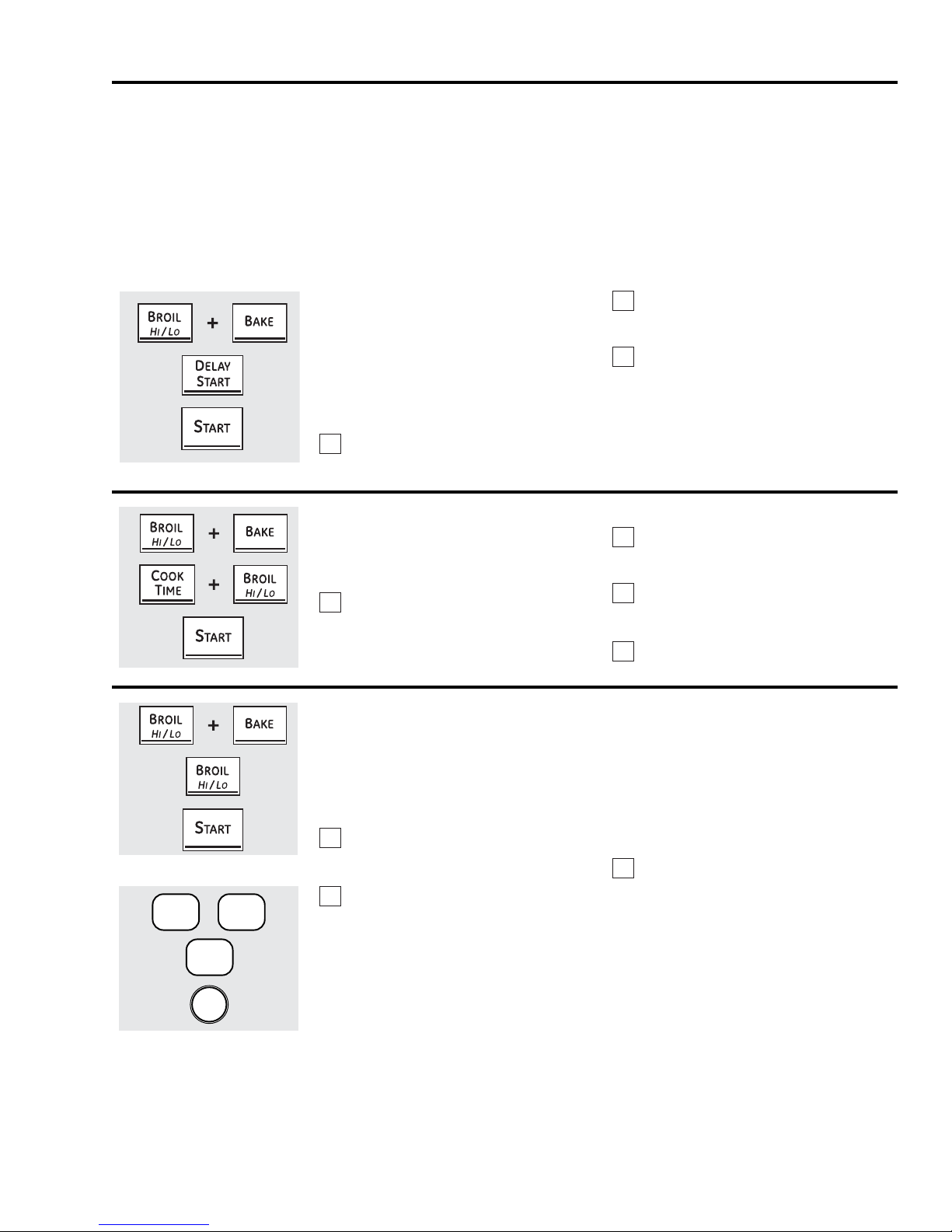
Special features of your oven control.
Your new touch pad control has additional features that you may choose to use. The following are the features and how you may
activate them.
The special feature modes can only be activated while the display is showing the time of day. They remain in the control’s memory
until the steps are repeated.
To enter a special feature for either oven, you must fi rst touch the upper oven BROIL HI/LO and BAKE pads at the same time. The
lower oven BROIL HI/LO and BAKE pads will not activate special features.
When the display shows your choice, touch the START pad. The special features will remain in memory after a power failure, except
for the Sabbath feature, which will have to be reset.
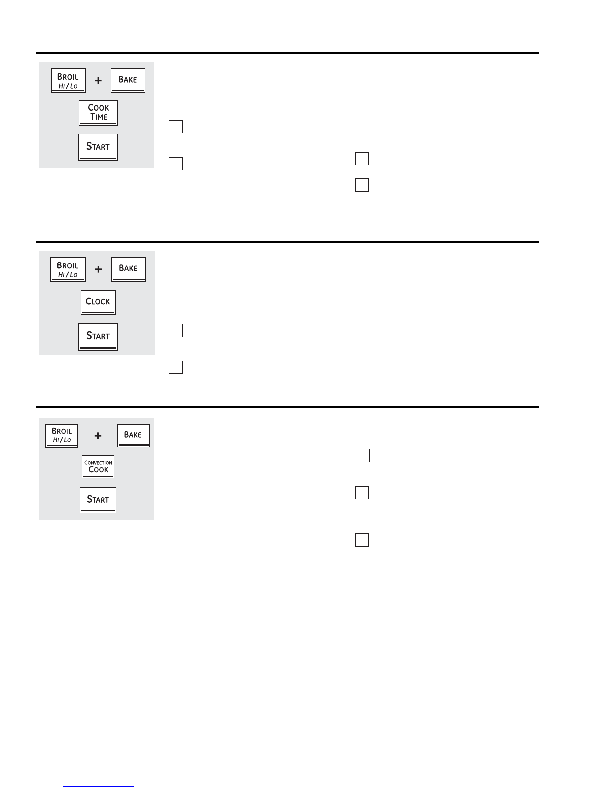
12-Hour Shutdown
With this feature, should you forget and leave
the oven on, the control will automatically
turn off the oven after 12 hours during baking
functions or after 3 hours during a broil
function.
If you wish to turn OFF this feature, follow the
steps below.
Touch the upper oven BROIL HI/LO and
1
BAKE pads at the same time until the
display shows SF.
Fahrenheit or Celsius Temperature Selection
Your oven control is set to use the Fahrenheit
temperature selections, but you may change
this to use the Celsius selections.
Touch the upper oven BROIL HI/LO and
1
BAKE pads at the same time until the
display shows SF.
Touch the DELAY START pad until
2
no shdn (no shut-off) appears in the
display.
Touch the START pad to activate the no
3
shut-off and leave the control set in this
special features mode.
Touch the COOK TIME and BROIL HI/LO
2
pads at the same time. The display will
show F (Fahrenheit).
Touch the COOK TIME and BROIL HI/
3
LO pads again at the same time. The
display will show C (Celsius).
Touch the START pad.
4
BAKE
+
KITCHEN
TIMER
ON/OFF
START
(on some models)
BROIL
HI/LO
Tones at the End of a Timed Cycle
At the end of a timed cycle, 3 short beeps will
sound followed by one beep every 6 seconds
until the CLEAR/OFF pad is touched. This
continual 6-second beep may be cancelled.
To cancel the 6-second beep:
Touch the upper oven BROIL HI/LO and
1
BAKE pads at the same time until the
display shows SF.
Touch the BROIL pad. The display
2
shows CONTI BEEP (continuous beep).
Touch the BROIL pad again. The display
shows SINGLE BEEP. (This cancels the
one beep every 6 seconds.)
OR
Touch the KITCHEN TIMER ON/OFF pad.
The display shows CON BEEP (continual
beep). Touch the KITCHEN TIMER ON/
OFF pad again. The display shows
BEEP. (This cancels the one beep every
6 seconds.)
Touch the START pad.
3
– 11 –
(Continued next page)
Special features of your oven control.
Tone Volume
This feature allows you to adjust the tone
volumes to a more acceptable volume. There
are three possible volume levels.
Touch the upper oven BROIL HI/LO and
1
BAKE pads at the same time until the
display shows SF.
Touch the COOK TIME pad. The display
2
will show 2 BEEP. This is the middle
volume level.
Touch the COOK TIME pad again. The
display will show 3 BEEP. This is the
loudest volume level.
12-Hour, 24-Hour or Clock Blackout
Your control is set to use a 12-hour clock.
If you would prefer to have a 24-hour military
time clock or black out the clock display,
follow the steps below.
Touch the upper oven BROIL HI/LO and
1
BAKE pads at the same time until the
display shows SF.
Touch the CLOCK pad once. The display
2
will show 12 hr. If this is the choice you
want, touch the START pad.
Touch the COOK TIME pad again. The
display will show 1 BEEP. This is the
quietest volume level.
For each time the level is changed, a
tone will sound to provide an indication
of the volume level.
Choose the desired sound level (1 BEEP,
3
2 BEEP, 3 BEEP).
Touch the START pad to activate the
4
level shown.
Touch the CLOCK pad again to change to the
24-hour military time clock. The display will
show 24 hr. If this is the choice you want, touch
the START pad.
Touch the CLOCK pad again to black out the
clock display. The display will show OFF. If this is
the choice you want, touch the START pad.
Note: If the clock is in the black-out mode, you
will not be able to use the Delay Start function.
Auto Recipe™ Conversion
When using convection bake, the
Auto Recipe™ Conversion feature will
automatically convert entered regular
baking temperatures to convection baking
temperatures.
This feature is activated so that the display
will show the actual converted (reduced)
temperature. For example, if you enter a
regular recipe temperature of 350°F and
touch the START pad, the display will show
CON and the converted temperature of
325°F.
To deactivate the feature:
Touch the upper oven BAKE and BROIL
1
HI/LO pads at the same time until the
display shows SF.
Touch the CONVECTION COOK pad.
2
The display will show CON ON. Touch
the CONVECTION COOK pad again. The
display will show CON OFF.
Touch the START pad.
3
To reactivate the feature, repeat steps 1–3
above but touch the START pad when CON ON
is in the display.
– 12 –
Using the Sabbath feature.
.
(Designed for use on the Jewish Sabbath and Holidays)
The Sabbath feature can be used for baking/roasting only. It cannot be used for convection, broiling, self-cleaning or Delay Start
cooking.
Note: The oven light comes on automatically when the door is opened and goes off when the door is closed. The bulb may be
removed. On models with a light switch on the control panel, the oven light may be turned on and left on.
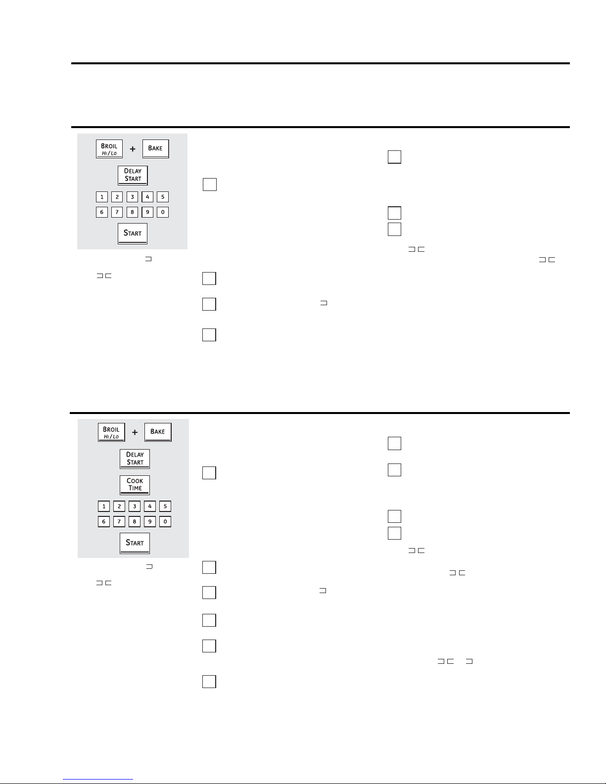
How to Set for Regular Baking/Roasting
When the display shows , the
oven is set in Sabbath. When the display
shows , the oven is baking/roasting
Make sure the clock shows the correct time
of day and the oven is off.
Touch and hold both the upper oven
1
BROIL HI/LO and BAKE pads, at the
same time, until the display shows SF.
Note: If bake or broil appears in the
display, the BROIL HI/LO and BAKE
pads were not touched at the same
time. Touch the CLEAR/OFF pad and
begin again.
Tap the DELAY START pad until SAb
2
bAtH SAb appears in the display.
Touch the START pad and will appear
3
in the display.
Touch the BAKE pad on the upper oven.
4
No signal will be given.
Using the number pads, enter the
5
desired temperature between 170°F
and 550°F. No signal or temperature
will be given. There is no default
temperature.
Touch the START pad on the oven.
6
After a random delay period of
7
approximately 30 seconds to 1 minute,
will appear in the display indicating
that the oven is baking/roasting. If
doesn’t appear in the display, start again
at Step 4.
To adjust the oven temperature, touch the
BAKE pad, enter the new temperature using the
number pads and touch the START pad.
Note: The CLEAR/OFF and COOK TIME pads are
active during the Sabbath feature.
When the display shows
oven is set in Sabbath. When the display
shows
, the oven is baking/roasting.
, the
How to Set for Timed Baking/Roasting―Immediate Start and Automatic Stop
Make sure the clock shows the correct time
of day and the oven is off.
Touch and hold both the upper oven
1
BROIL HI/LO and BAKE pads, at the
same time, until the display shows SF.
Note: If bake or broil appears in the
display, the BROIL HI/LO and BAKE
pads were not touched at the same
time. Touch the CLEAR/OFF pad and
begin again.
Tap the DELAY START pad until SAb
2
bAtH SAb appears in the display.
Touch the START pad and will appear
3
in the display.
Touch the COOK TIME pad on the upper
4
oven. No signal will be given.
Touch the number pads to set the
5
desired length of cooking time between
1 minute and 9 hours and 99 minutes.
Touch the START pad.
6
Touch the BAKE pad. No signal will be
7
given.
Using the number pads, enter the
8
desired temperature. No signal or
temperature will be given. There is no
default temperature.
Touch the START pad on the oven.
9
After a random delay period of
10
approximately 30 seconds to 1 minute,
will appear in the display
indicating that the oven is baking/
roasting. If doesn’t appear in the
display, start again at Step 7.
To adjust the oven temperature, touch the
BAKE pad, enter the new temperature using the
number pads and touch the START pad.
When cooking is fi nished, the display will
change from to and 0:00 will appear,
indicating that the oven has turned OFF but is
still set in Sabbath. Remove the cooked food.
– 13 –
(Continued next page)
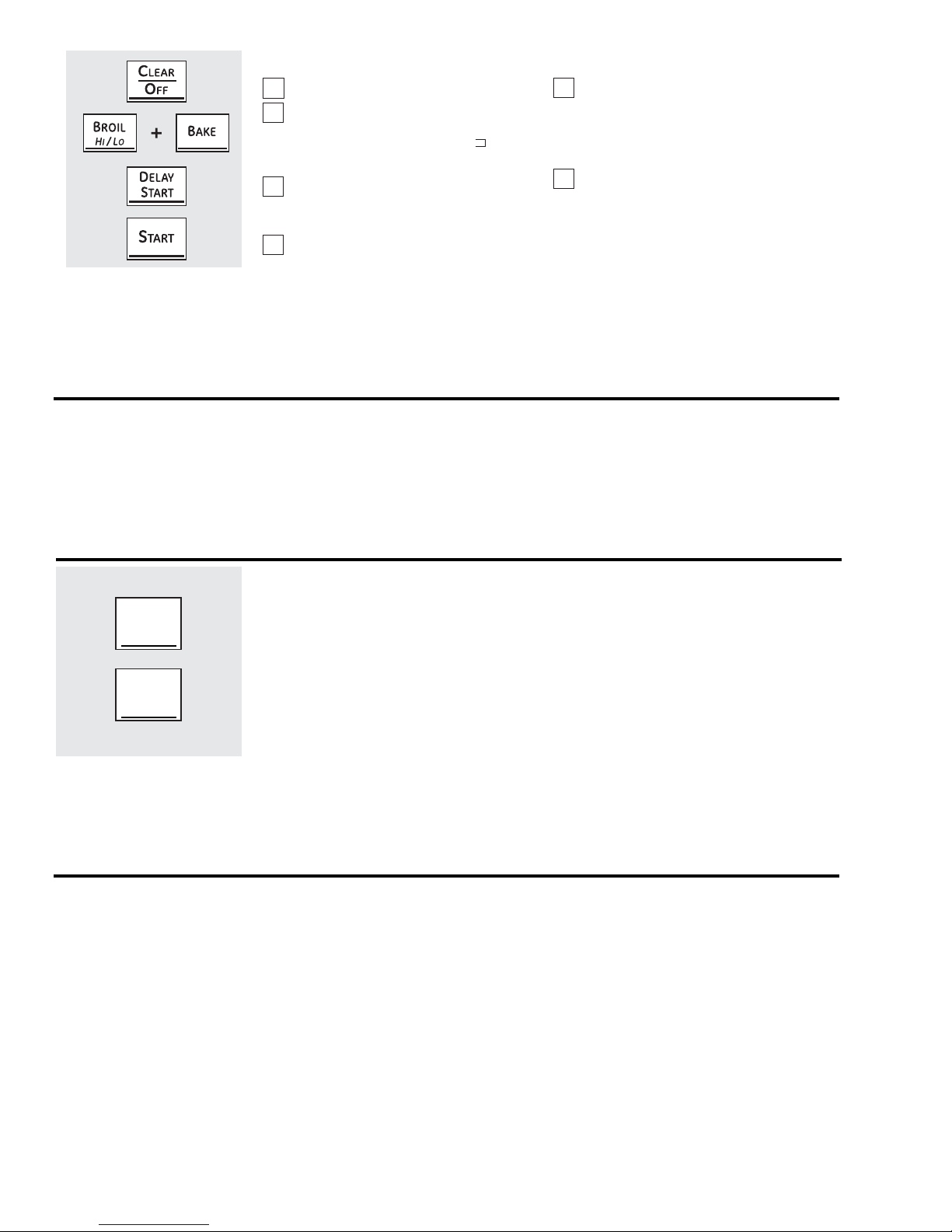
How to Exit the Sabbath Feature
WARMING
DR AW ER
ON /O
FF
WARMING
DR AW ER
SE TTIN G
Touch the CLEAR/OFF pad.
1
If the oven is cooking, wait for a random
2
delay period of approximately 30
seconds to 1 minute, until only is in
the display.
Touch and hold both the BROIL HI/LO
3
and BAKE pads, at the same time, until
the display shows SF.
Tap the DELAY START pad until 12 shdn
4
or no shdn appears in the display.
Choose 12 shdn, indicating that the
5
oven will automatically turn off after
12 hours or no shdn, indicating that
the oven will not automatically turn off
after 12 hours.
Press START when the option that you
6
want is in the display (12 shdn or no
shdn).
Note: If a power outage occurred while
the oven was in Sabbath, the oven will
automatically turn off and stay off even
when the power returns. The oven control
must be reset.
Using the warming drawer.
FOOD POISON HAZARD: Bacteria may grow in food at temperatures below 140°F.
• Always start with hot food. Do not use warm settings to heat cold food.
• Do not warm food for more than 2 hours.
Failure to follow these instructions may result in food borne illness.
The warming drawer will keep hot, cooked foods at serving temperature. Always start with hot food.
Do not use to heat cold food other than crisping crackers, chips or dry cereal.
ARMING
RAWER
/O
FF
ARMING
RAWER
SETTING
To Use the Warming Drawer
The warming drawer will keep hot, cooked
foods at serving temperature. Always start
with hot food.
Touch the WARMING DRAWER ON/OFF
pad. The WARMING DRAWER ON/OFF pad
is lit. SET WARMING DRAWER appears on
the display, and the WARMING DRAWER
SETTING pad begins to blink. Touch the
WARMING DRAWER SETTING pad within
10 seconds to toggle between HI, Std, or LO
temperature selections.
When Using the Warming Drawer
The warming drawer will keep hot, cooked
foods warm. Always start with hot food. Do
not use to heat cold food other than crisping
crackers, chips or dry cereal.
Do not line the warming drawer or pan
with aluminum foil. Foil is an excellent heat
insulator and will trap heat beneath it. This
will upset the performance of the drawer
and could damage the interior fi nish.
Allow approximately 25 minutes for the
warming drawer to preheat.
Do not put liquid or water in the warming
■
drawer.
Note: A duty cycle regulates temperature:
• Low Temperature = 165° +/- 25°F.
• Standard Temperature = 175° +/- 25°F.
• High Temperature = 180° +/- 25°F.
To cancel, touch the WARMING DRAWER ON/
OFF pad.
Note: Touching the CLEAR/OFF pad does not
turn off the warming drawer.
All foods placed in the warming drawer
■
should be covered with a lid or aluminum
foil. When warming pastries or breads, the
cover should be vented to allow moisture
to escape.
Food should be kept hot in its cooking
■
container or transferred to a heat-safe
serving dish.
Note: Plastic containers or plastic wrap will
melt if in direct contact with the drawer, pan
or a hot utensil. Melted plastic may not be
removable and is not covered under your
warranty.
Remove serving spoons, etc., before
■
placing containers in warming drawer.
– 14 –
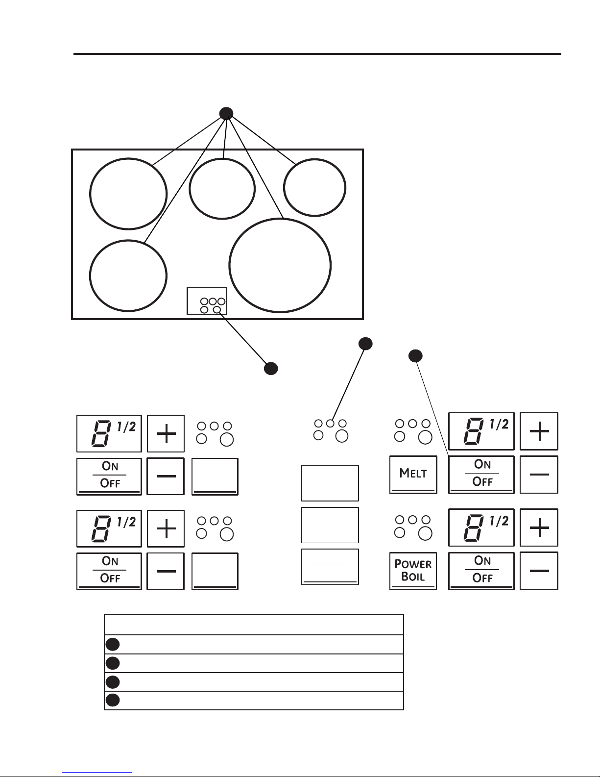
Features of your cooktop.
S
IMMER
S
IMMER
Throughout this manual, features and appearance may vary from your model.
1
1
7" - 2500 Watts
7" - 2500 Watts
Warmer
100 Watts
6" - 1800 Watts
11" - 3700 Watts
1
3
W
ARMING ZONE
1
2
1
4
S
S
Feature Index
1
Cooking Elements
1
1
2
Element Location Indicator (one for each element)
1
Hot Surface Indicator Light Area
3
1
4
Cooking Element ON/OFF Control
IMMER
IMMER
S
ELECT
O
O
– 15 –
N
FF
Using the surface units—Touch pad-controlled models.
Surface Unit Cook Settings
The cooktop offers 19 power levels. Power
levels range from “L” to H in precise halfstep
increments. For example: 1, 1-1/2, 2, 2-1/2
and up to H.
The power level with a fraction indicates
the additional half-step setting. You
may hear clicking sounds indicating
the control is maintaining your desired
setting.
Power Level “L”, the lowest setting, is
recommended for “Keep Warm.”
The power level increases one-half level with
each touch.
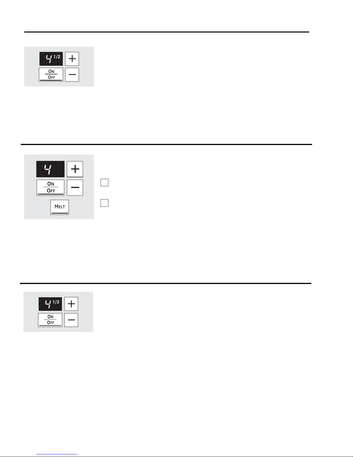
Single Surface Unit―Cook Settings
To turn on a single surface unit:
Touch the ON/OFF pad, then touch the
1
(+)/(–) pad.
Use the (+)/(–) pad to choose the desired
2
power setting.
To use the Melt feature:
Touch the ON/OFF pad, then touch MELT.
The element will automatically set to a
predetermined setting and “L” will be
displayed.
To use the Simmer feature:
Touch the ON/OFF pad, then touch SIMMER.
The element will automatically set to a
predetermined setting and “3” will be
displayed. Adjust, using the (+)/(–) pad to
increase or decrease the simmer rate.
To turn off a single surface unit, touch the
ON/OFF pad again.
Flashing Power Level in the Display
If a pan is removed or moved off-center
from the cooking ring during the cooking
process, the control will fl ash the current
selected power level. The fl ashing power
level indicates that the pan is no longer
detected. After 30 seconds, the element will
be deactivated and the display will turn off.
If the pan is returned to the surface element
within 30 seconds, the power level will stop
fl ashing and cooking will resume.
– 16 –
(Continued next page)
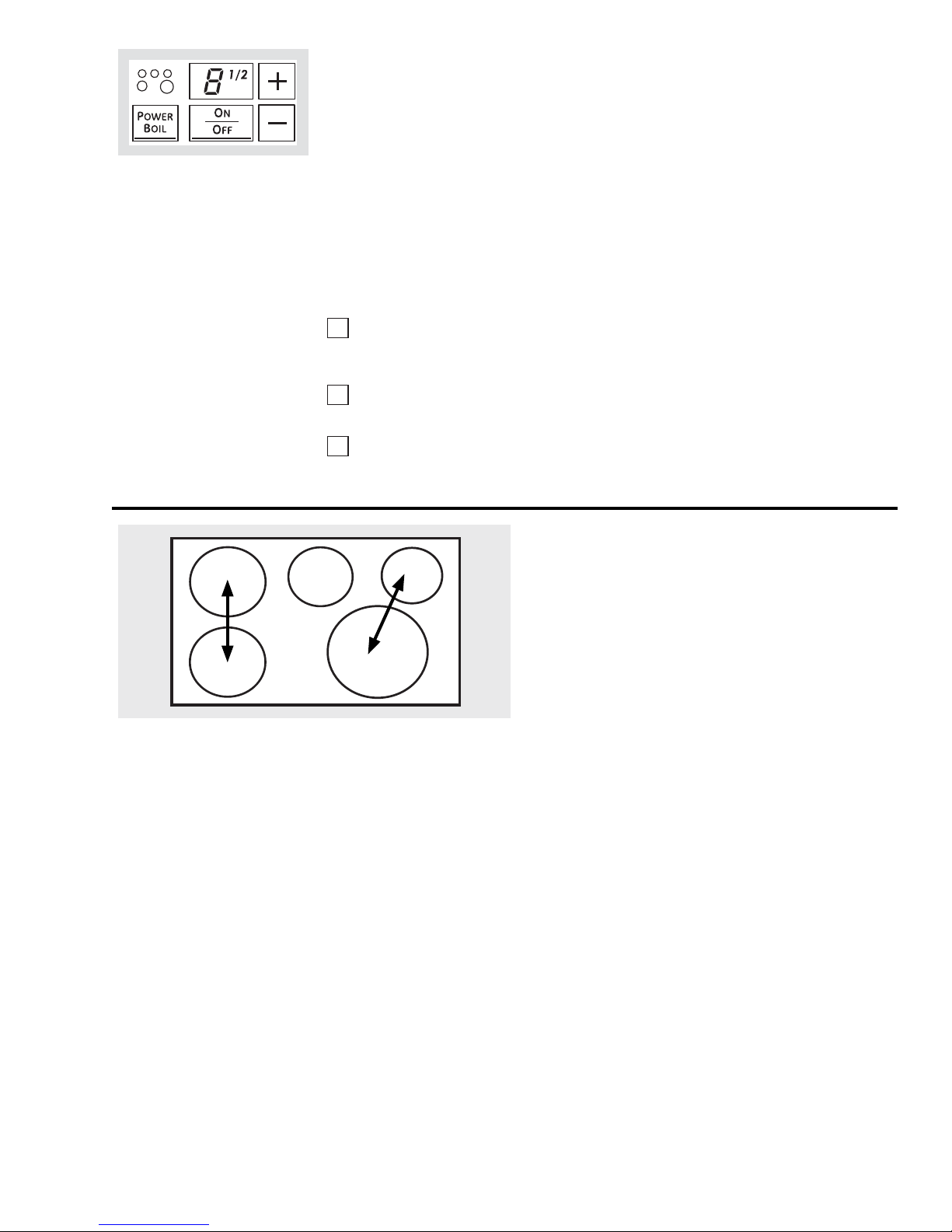
Power Boil
Power Boil is the highest power level,
designed for large quantity rapid cooking
and boiling. Power Boil will operate for a
maximum of 10 minutes. After 10 minutes, it
will automatically revert to power level 9.
Power Boil may be repeated after the initial
10 minute cycle.
CAUTION: Do not leave a pot unattended
while in the Power Boil mode.
To start the Power Boil power setting:
Place a pan matching the size of the
1
induction element over the selected
indicator ring.
Touch the ON/OFF pad, then touch the
2
POWER BOIL pad.
The element will be set to the Power
3
Boil setting and "H" will appear in the
display.
Power Sharing
NOTE: If the pan is removed, the display will
fl ash “H”. After 30 seconds, the element will
turn off automatically.
Sounds you may hear:
You may hear a slight “buzz” sound when
cooking with the or high mode. This is
normal. The sound depends on the type of
pot being used. Some pots will “buzz” louder
depending on the material. A “buzz” sound
may be heard if the pan contents are cold.
As the pan heats, the sound will decrease. If
the power level is reduced, the sound level
will go down.
Four burner cooktops are divided into two separate heating
zones. The right and left side cooking zones are powered
by separate and independent induction generators. Each
generator controls the 2 elements in the zone.
Power Sharing is activated when both elements in the same
cooking zone are activated and one element is set for Boost
(H). The element that is not set for Boost will change to a
lower power level. This is called Power Sharing. When Boost
operation is complete (10 minutes), the other element may
be reset to any power level. Both elements can operate
simultaneously at normal power level settings of “L” to 9. If
the right rear element is operating on power level H and the
right front element is set between 7 1/2 to 9, the right front
will be reduced to power level 7.
IMPORTANT NOTE FOR FOUR BURNER MODELS:
The elements on the right side share one generator. Both
elements can operate at any non-Boost (level L to 9) power
level at the same time. If the large front element is set for
"H" or Boost, the smaller element at the right rear will be
deactivated or turned off automatically. The smaller right
rear element can be activated and set for any power level
after the Boost operation of the larger element is completed
(10 minutes).
– 17 –
(Continued next page)
Setting the controls
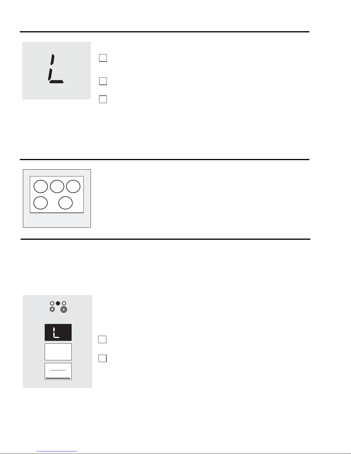
HOT COOKTOP
Using the "L" Low Setting
1
2
3
CAUTION: Do not warm
food on the “L” power level
for more than two hours.
HOT COOKTOP
Do not use plastic wrap to cover food. Plastic
may melt onto the surface and be very
diffi cult to remove.
Use only cookware recommended for this
cooktop.
Hot Cooktop Indicator Light
A HOT COOKTOP indicator light (one
for each cooking element) will glow
immediately when any element is
activated. The indicator light(s) glow
when the glass surface is hot, and will
remain on until the surface has cooled to a
temperature that is safe to touch.
Place a pan with food onto the
induction element. The pan size should
match the indicator ring.
Touch the ON/OFF pad. “5” will fl ash in
the display.
Touch the (-) pad until the display reads
“L.” A sound will beep.
The Low setting will keep hot, cooked food at
serving temperature. Always start with hot
food. Do not use to heat cold food.
Placing uncooked or cold food on surface
element set for Low could result in foodborne
illness.
For best results, all food set for Low should be
covered with a lid or aluminum foil. Pastries or
breads should be vented to allow moisture to
escape.
Always use pot holders or oven mitts when
removing food from the element set for Low
as cookware and plates will be hot.
WARNING: FOOD POISON HAZARD: Bacteria may grow in food at temperatures below 140°F.
• Always start with hot food. Do not use warm settings to heat cold food.
• Do not warm food for more than 2 hours.
Failure to follow these instructions may result in food borne illness.
Using the Warming Zone
The WARMING ZONE is located in the back
W
ARMING ZONE
S
ELECT
O
N
O
FF
center of the glass surface.
To use the WARMING ZONE:
Touch the WARMING ZONE ON/OFF
1
pad.
To select the desired control setting,
2
touch the SELECT pad once for LO,
twice for MED, or three times for HI.
To turn off the WARMING ZONE:
Touch the WARMING ZONE ON/OFF pad.
For best results, all foods on the WARMING
ZONE should be covered with a lid or
aluminum foil.
Always use pot holders or oven mitts when
removing food from the WARMING ZONE,
as cookware will be hot.
Do not use plastic wrap to cover food.
■
Plastic may melt onto the surface and
be very diffi cult to clean.
Use only cookware recommended for
■
top-of-range cooking.
– 18 –

Operation Overview
The controls for the oven system consist of a
key panel touch-fi lm-on-glass assembly and
main logic board with its model-select resistor
plug located in the control panel. There is also
one RTD oven sensor, optional meat probe,
and a motor door lock assembly with position
switches. The oven and warming drawer are
controlled by relays found on the RPSM main
board.
Lock
Motor
Oven Flow Chart
Touch
Control
MLB
Main Logic Board
RPSM
Relay Power
Supply Module
Heating
Elements
Oven
Sensor
Convection
Fan
There are four induction cooktop coils. The
controls for the cooktop module consist of
two burner touch boards connected to and
working through the main logic board. The
main logic board is connected via the local
interconnect network (LIN) serial wire to the
cooktop module and a relay power supply
board (RPSM) located on the back of the unit.
A fi fth cooktop element is a resistive warmer
controlled by RPSM relays. (See
and Wiring Diagrams.) No relay boards or line
Schematics
voltage are brought to the control panel.
The bridge board contains the surface on/
hot cooktop indicator lights. The induction
module cooling fan connection is also located
on this board. This board bridges the Linbus
connections from the fi lter board and main
logic board along with the RPSM.
Induction Flow Chart
Touch
Control
Inputs
MLB
Main Logic Board
RPSM
Relay Power
Supply Module
Generator
Board
Outputs
Bridge
Board
Filter
Board
Processing
Generator
Board
Outputs
– 19 –
Element
Element
Linbus Operating Voltage
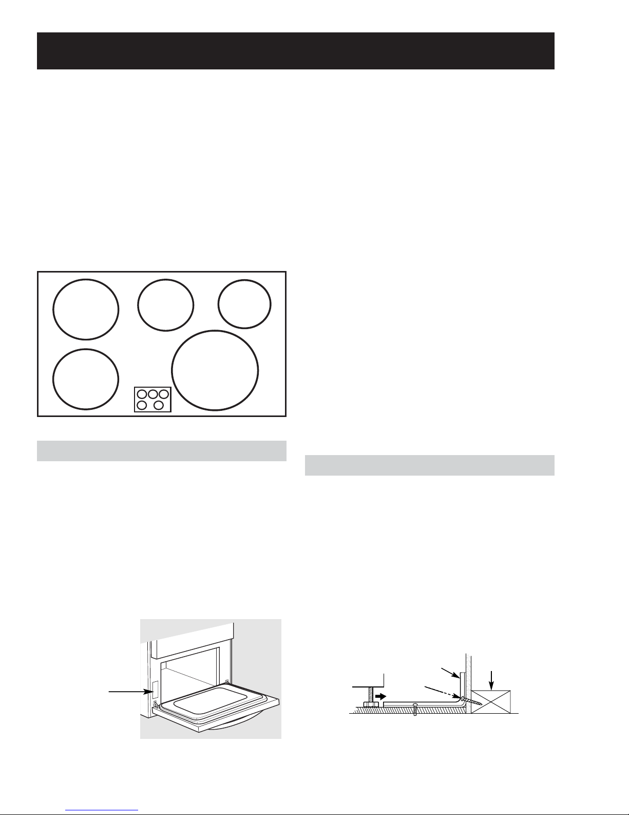
Installation
Location of
model rating
plate
Typical installation of anti-tip bracket attachment to wall
Bracket
Screw must
enter wood
or metal
Wall plate
BOOST MODE AND POWER SHARING
The induction coils on the left side are paired
for power sharing and both cannot be used
simultaneously on “H.” The last coil set to “H” will
remain on “H” and the other coil will reduce to
power level “7½.” The induction coils on the right
side are likewise paired for power sharing. The last
coil set to “H” will remain on “H” and the other coil
will reduce accordingly (RF coil will reduce to “7” and
the RR coil will shut off).
Element Size and Wattage
7" - 2500 Watts
7" - 2500 Watts
Warmer
100 Watts
11" - 3700 Watts
6" - 1800 Watts
You must use a 3-wire, single-phase A.C. 08Y/120
Volt or 240/120 Volt, 60 hertz electrical system. If
the electrical service provided does not meet the
above specifi cations, have a licensed electrician
install an approved outlet.
WARNING: ALL NEW CONSTRUCTIONS, MOBILE
HOMES AND INSTALLATIONS WHERE LOCAL CODES
DO NOT ALLOW GROUNDING THROUGH NEUTRAL,
REQUIRE A 4-CONDUCTOR UL-LISTED RANGE CORD.
Use only a 3-conductor or a 4-conductor UL-listed
range cord. These cords may be provided with ring
terminals on wire and a strain relief device.
A range cord rated at 40 amps with 125/250
minimum volt range is required. A 50-amp range
cord is not recommended but, if used, it should
3
/
8
be marked for use with nominal 1
-in. diameter
connection openings. Care should be taken to
center the cable and strain relief within the knockout
hole to keep the edge from damaging the cable.
Because range terminals are not accessible after
range is in position, fl exible service conduit or cord
must be used.
Electrical Requirements
Caution: For personal safety, do not use an
extension cord with this appliance.
This appliance must be supplied with the proper
voltage and frequency, and connected to an
individual properly grounded branch circuit,
protected by a circuit breaker or fuse having
amperage as specifi ed on the rating plate. The
rating plate is located on the left-hand side of the
lower oven front frame.
Anti-Tip Bracket
WARNING: The range must be secured by the anti-
tip bracket supplied. Unless properly installed, the
range could be tipped by stepping or sitting on the
doors. Injury may result from spilled hot liquids or
from the range itself.
An anti-tip bracket is supplied with instructions for
installation in a variety of locations. The instructions
include all necessary information to complete the
installation. Read the safety instructions and the
instructions that fi t your situation before beginning
installation.
– 20 –
 Loading...