

GE JGP989, Profile JGP989 Series Technical Service Manual
C
GE Consumer Home Services Training
TECHNICAL SERVICE GUIDE
Profile
Gas-on-Glass
Cooktop
MODEL SERIES:
JGP989
PUB # 31-9080 06/01

!
IMPORTANT SAFETY NOTICE
The information in this service guide is intended for use by
individuals possessing adequate backgrounds of electrical, electronic, and mechanical experience. Any attempt to repair a major
appliance may result in personal injury and property damage. The
manufacturer or seller cannot be responsible for the interpretation
of this information, nor can it assume any liability in connection
with its use.
WARNING
If the information in this manual is not followed exactly, a fire or
explosion may result causing property damage, personal injury or
death. If you smell gas:
- Do not try to light any appliance.
- Do not touch any electrical switch; do not use any phone in
the building.
- Immediately call the gas supplier from a neighbor’s phone.
Follow the gas supplier’s instructions.
- If you cannot reach the gas supplier, call the fire department.
WARNING
To avoid personal injury, disconnect power before servicing
this product. If electrical power is required for diagnosis or test
purposes, disconnect the power immediately after performing the
necessary checks.
RECONNECT ALL GROUNDING DEVICES
If grounding wires, screws, straps, clips, nuts, or washers
used to complete a path to ground are removed for service, they
must be returned to their original position and properly fastened.
GE Consumer Home Services Training
Technical Service Guide
Copyright © 2001
All rights reserved. This service guide may not be reproduced in whole or in
part in any form without written permission from the General Electric Company.

Table of Contents
Table of Contents
Introduction . . . . . . . . . . . . . . . . . . . . . . . . . . . . . . . . . . . 2
Installation . . . . . . . . . . . . . . . . . . . . . . . . . . . . . . . . . . . 3
Conversion to LP (Propane) Gas . . . . . . . . . . . . . . . . . . . . . . . 4
Specifications and Nomenclature5 . . . . . . . . . . . . . . . . . . . . . . 8
Warranty Information . . . . . . . . . . . . . . . . . . . . . . . . . . . . . . 9
Cooktop Features and Controls. . . . . . . . . . . . . . . . . . . . . . . . 10
Mechanical Disassembly . . . . . . . . . . . . . . . . . . . . . . . . . . . . 13
Troubleshooting . . . . . . . . . . . . . . . . . . . . . . . . . . . . . . . . 19
Component and Connector Locator Views . . . . . . . . . . . . . . . . . . 21
Schematics . . . . . . . . . . . . . . . . . . . . . . . . . . . . . . . . . . . 22
Parts List . . . . . . . . . . . . . . . . . . . . . . . . . . . . . . . . . . . . 24
[[Title]]
– 1 –
Introduction
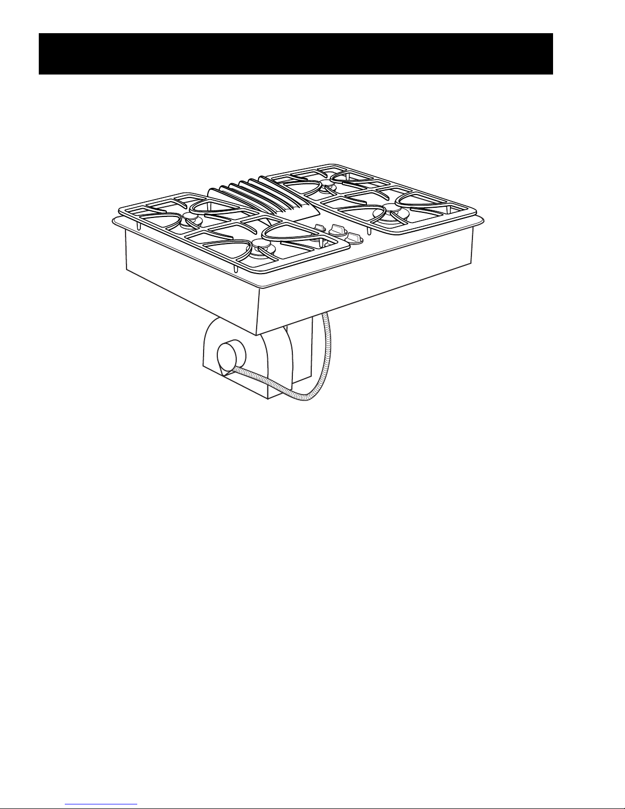
The new Profile Gas-on-Glass Downdraft Model
cooktops make an eloquent statement of style,
convenience, and kitchen planning flexibility .
Whether chosen for its purity of design, attention
to detail, or both of these reasons–you’ll find these
downdraft gas cooktops’ superior blend of form
and function will be a delight for years to come.
These cooktops contain several new features,
such as glass cooktop surfaces, sealed burners,
and a 400-CFM downdraft venting system.
The information on the following pages will help
you service these cooktops effectively and
efficiently.
– 2 –
Installation
Never reuse old flexible
connectors. The use
of old flexible connectors
can cause gas leaks
and personal injury.
Always use NEW
flexible connectors
when installing a
gas appliance.
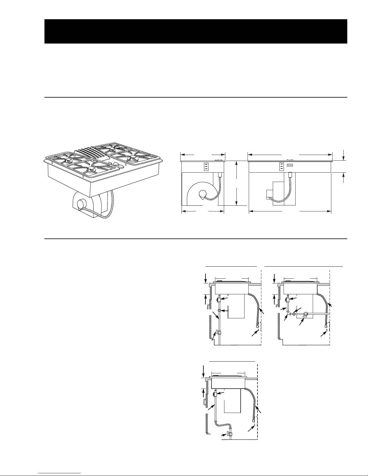
205⁄8″
Cutout
205⁄8″
Cutout
205⁄8″
Cutout
6″ Min.
Min.
Electrical
outlet:
12″ above
cabinet
floor
Electrical
outlet:
12″ above
cabinet
floor
Pressure
regulator
Pressure
regulator
Pressure
regulator
Electrical
outlet:
12″ above
cabinet
floor
6″ Min.
Shut-off
valve
Shut-off
valve
Shut-off
valve
″ Pipe
1
⁄2″ Pipe
1
⁄2″ Pipe
Electrical
cord
42″ long
Electrical
cord
42″ long
Electrical
cord
42″ long
Solid Pipe Connection
Solid Pipe Connection with Elbow
Union
Elbow
Union
Flexible Connection
217⁄8″
201⁄2″
19″
6″ Dia.
297⁄8″
6″
283⁄4″
WARNING: Before beginning the installation,
switch power off at the service panel and lock the
service disconnecting means. When the service
disconnecting means cannot be locked, securely
fasten a warning tag to the service panel.
30-in. Cooktop Dimensions
Dimensions for reference only .
Unit shown fully assembled.
Unit must be vented to the outside!
Gas Supply
These cooktops are designed to operate on natural
gas at 4 in. of water column pressure or on LP gas
at 10 in. of water column pressure. For proper
operation, the maximum inlet pressure to the
regulator must be no more than 10 in. of water
column pressure for natural gas and 14 in. of
water column pressure for LP gas.
Gas Supply Shutoff V alve
The cooktop itself is not equipped with a gas shutof f valve. If installed correctly, a shutoff valve will be
in the main gas supply line “upstream” of the
appliance pressure regulator .
Measuring the Gas Pressure
Supplied to the Burners
Connect the tubing supplied with a manometer
over one end of the manometer . Remove a burner
cap and head from the appliance and place the
other end of the tubing over the burner orifice. T u rn
on the gas to the orifice you are testing and light at
least one other burner to serve as a load.
Before You Begin...
Note: The complete installation instructions
are inclosed with the
Use and Care Manual
Carefully read and follow these instructions.
6”
1/2
– 3 –
.
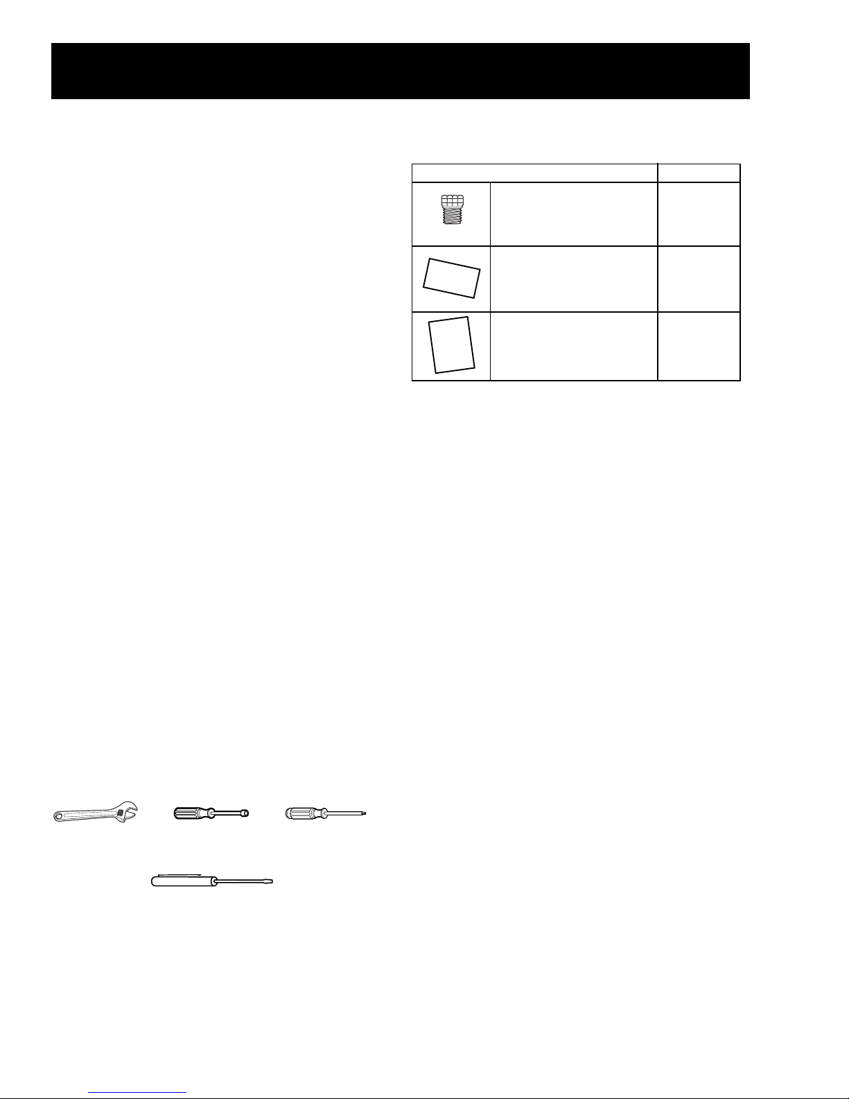
PART QUANTITY
Brass orifices 4
Stick-on rating label 1
Installation instructions 1
Conversion to LP (Propane) Gas
Adjustable wrench 9/32″ (7 mm) Nutdriver T15 Torx driver
Small, thin-blade flat screwdriver with approximately 1/8″
blade width is needed to access the calibration screw.
Note: Before you begin, read these
instructions completely and carefully.
The cooktop is factory set for natural gas
operation. T o use LP ( pr opane) gas, the regulator
and burner orifices must be converted. The LP
orifice spuds for the cooktop burners can be
located within the literature package shipped with
the unit.
If you convert to LP gas, keep instructions and
natural gas orifices to convert back for use with
natural gas.
Product failure due to improper installation is not
covered under the GE Appliances Warranty.
WARNING: If you are using LP (propane) gas, all
adjustments described in the following steps must
be made before attempting burner adjustments or
using the cooktop.
WARNING: This conversion kit shall be installed
by a qualified service agency in accordance with
the manufacturer’s instructions and all applicable
codes and requirements of the authority having
jurisdiction. If the information in these instructions
is not followed exactly , a fire, explosion, or
production of carbon monoxide may result,
causing property damage, personal injury , or loss
of life. The qualified service agency is responsible
for the proper installation of this kit. The installation
is not proper and complete until the operation of
the converted appliance is checked as specified in
the manufacturer’s instructions supplied with the
kit.
Parts Included
Gas Supply
With the installation of this conversion kit, the
cooktop should operate on LP gas at 10 in. of
water column pressure.
The pressure regulator must be connected in
series with the manifold of the cooktop and must
remain in series with the supply line. For proper
operation, the maximum inlet pressure to the
regulator must be no more than 14 in. water
column pressure for LP gas.
When checking the regulator , the inlet pressure
must be at least 1 in. greater than the regulator
output setting. If the regulator is set for 10 in. of
water column pressure, the inlet pressure must be
at least 1 1 in.
T ools You Will Need
Note: Disconnect the cooktop and the individual
shutoff valve from the gas supply piping system
during any pressure testing of that system at test
pressures greater than 1/2 psig. Isolate the
cooktop from the gas supply piping system by
closing the individual manual shutoff valve to the
cooktop during any pressure testing of the gas
supply piping system at test pressures equal to or
greater than 1/2 psig.
– 4 –
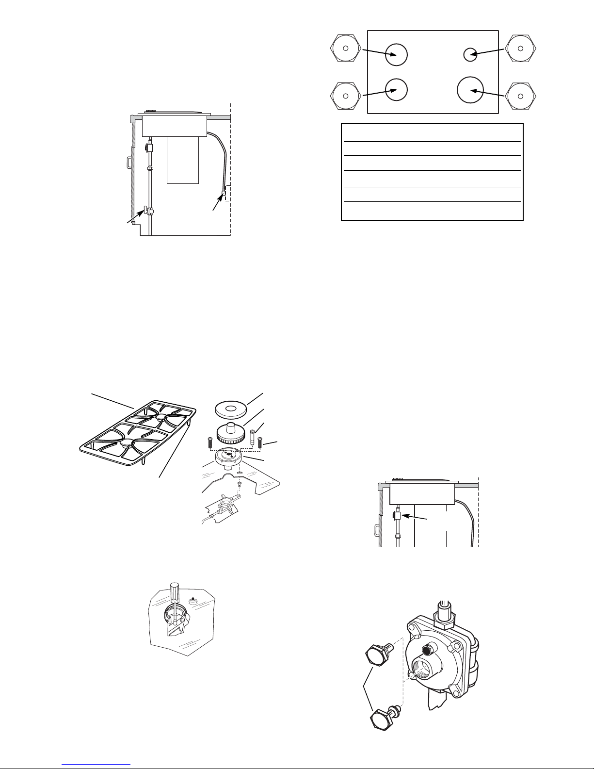
LP (Propane) Gas 10″ W. C . P.
Burner Output Rating in BTU/HR
Location BTUs Orifice Size
LF, LR 8,500 0.84 Lmm
RR 5,500 0.71 Lmm
RF 11,000 0.99 Lmm
Front
Pressure
regulator
Natural gas
LP gas
Nut
Turn OFF Gas and Electric Supply
Shut-off valve
Electrical supply
Grate
Brass
locator foot
Burner cap
Electrode
Burner base
Burner head
Burner
base
screw (2)
Before you begin, turn OFF the gas supply at the
shut-off valve. Disconnect the electrical supply
from the cooktop.
Convert Surface Burners
1. First remove, convert, and replace the left-side
surface burners and then the right-side surface
burners. Remove the grates, burner caps, and
burner heads. Remove the screws securing the
burner bases to the burners. Pull out the
electrodes without removing the electrode leads.
84
L
84
L
71
L
99
L
Note: For operation at elevations above 5000 ft.(1500 m),
equipment ratings shall be reduced at a rate of 2% for each
1000 ft. (300 m) above sea level before selecting
appropriately sized equipment, i.e., use smaller orifices.
Caution: When attaching the burner base to the
glasstop unit, tighten to 12 in./lbs max torque.
Overtightening will cause damage.
4. Replace the gaskets, burner bases, and
electrodes. Install the 2 screws in each burner
base. Do not overtighten. The maximum torque
is 10 in./lbs. Push the igniters all the way down
into the burner head.
2. Remove the brass orifice spud in the chimney
of each burner using a 9/32-in. (7 mm) nutdriver .
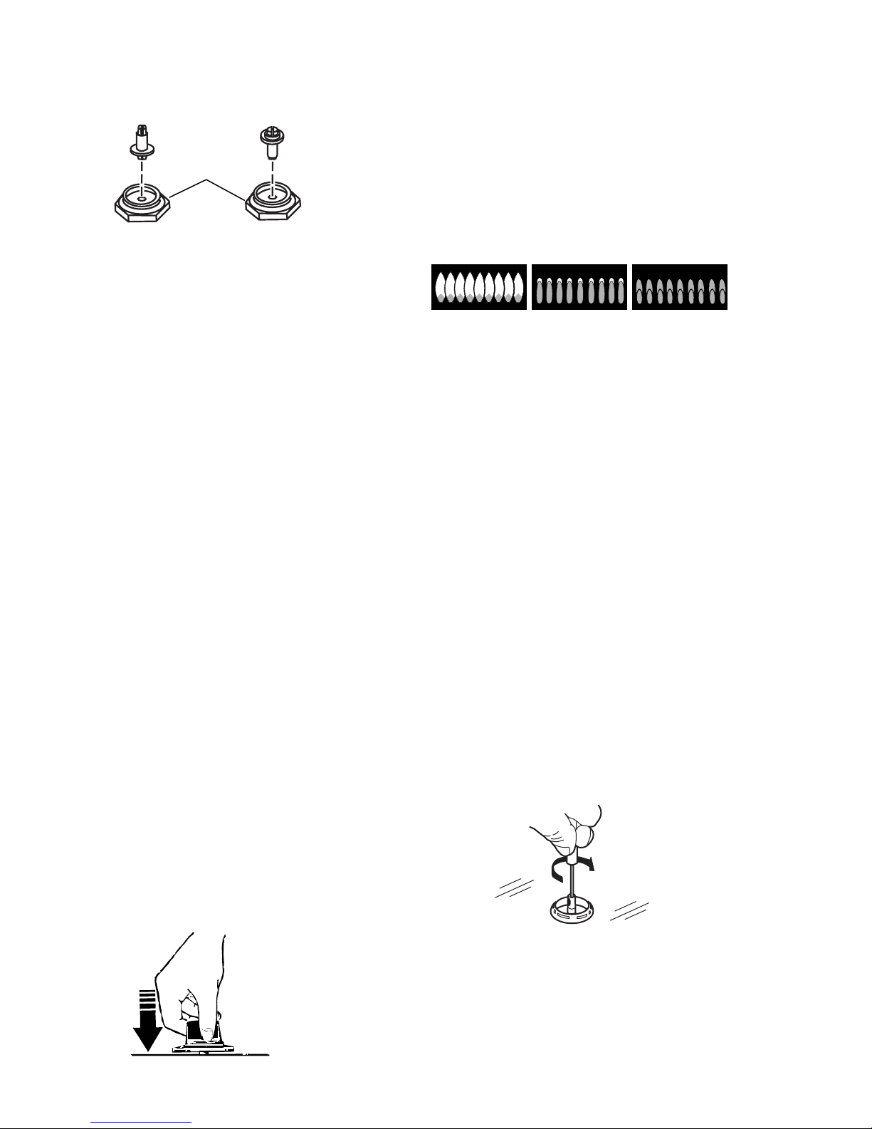
Note: The LP orifices are shorter than the natural
gas orifices.
3. Install the LP orifice spuds in their correct
positions by number .
5. Install the burner heads, burner caps, and
grates in their original burner positions.
Convert the Pressure Regulator
1. Locate the pressure regulator under the rear of
the cooktop.
2. Remove the nut from the pressure regulator
with an adjustable wrench.
– 5 –
3. Remove the plastic pin from the inside of the
Natural gas LP gas
Nut
A–Yellow flames
Call for service
B–Yellow tips
Normal for
LP gas
C–Soft blue flames
Normal for
natural gas
nut, turn the pin 180 degrees and snap the pin
back into the nut.
4. Reinstall the nut onto the regulator .
5. Apply the LP conversion label next to the rating
plate.
T est for Leaks
2. Push down one control knob and turn to the
LITE position. The igniter will spark and the
burner will light. The first test may require some
time while air is flushed out of the gas line.
3. Check to determine if your burner flames are
normal. If burner flames look like A, call for
service. Normal burner flames should look like
B or C, depending on the type of gas you use.
With LP gas, some yellow tipping on outer
cones is normal.
WARNING: Do not use a flame to check for leaks!
Do not use the cooktop until all connections have
been leak tested.
Perform leak test per the following instructions:
1. Purchase a liquid leak detector or prepare a
soap solution of one part water , one part liquid
detergent.
2. When all connections have been made, make
sure all cooktop controls are turned to OFF and
turn the gas supply valve to ON.
3. Apply the liquid leak detector or the soap solution around all connections from the shutoff
valve to the cooktop.
4. A leak is identified by a flow of bubbles from the
area of the leak.
5. If a leak is detected, turn the gas supply off.
T ighten the fitting. T urn the gas ON and test
again. If the leak persists, turn the gas supply
OFF and contact your dealer for assistance.
Do not attempt to operate the cooktop if a leak
is present.
4. Turn the knob to OFF.
5. Repeat the procedure for each burner .
Adjusting Low Flame (Simmer) Setting
WARNING: The following adjustments must be
made before turning on the burner . Failure to do so
could result in serious injury . Be sure pressure
regulator has been converted.
Note: The top burner valves have low flame/
simmer adjustment screws in the center of the
control shafts. A flashlight may be needed to
locate the screw . A small thin-blade screwdriver
(approximately 1/8-in. blade width) is needed to
access the screw .
1. Light 2 other burners and set the knobs to a
MEDIUM to HI setting.
2. Light the burner to be adjusted and turn the
knob to LOW .
Check Ignition
1. Connect electrical supply cord.
3. Remove the knob and insert a screwdriver into
the valve shaft.
4. T urn the adjustment screw until the flame
– 6 –
reaches the desired size.
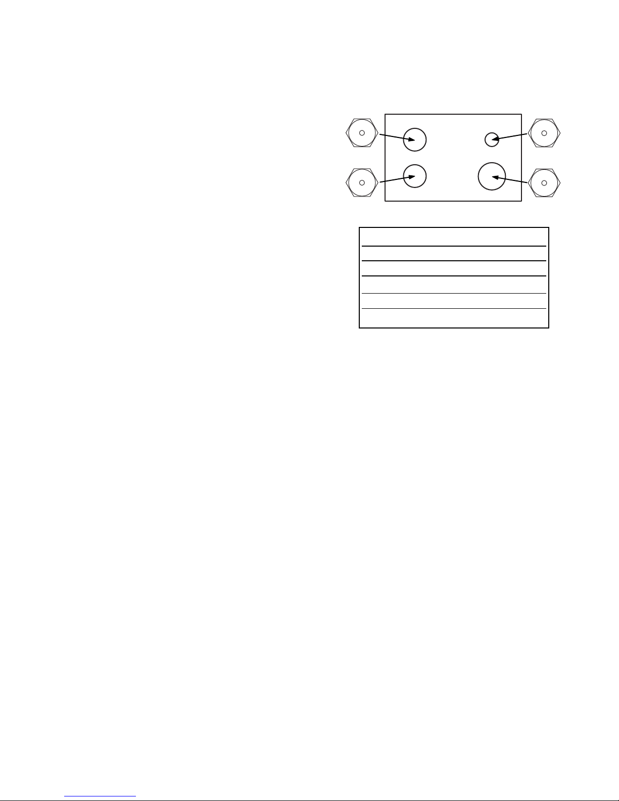
Front
Natural Gas 4″ W. C . P.
Burner Output Rating in BTU/HR
Location BTUs Orifice Size
LF, LR 9,100 1.50 Nmm
RR 5,500 1.22 Nmm
RF 11,500 1.69 Nmm
5. Perform a flame stability test with the downdraft
fan on HIGH.
Flame Adjustments
Note: The burners do not have air shutters adjust-
ments and use nonadjustable orifices. If the
flame lifts off the burner , or if you experience
yellow-tipped flames and/or soot in the flames,
be sure to check the following:
1. Gas pressure: 4-in. W .C.P. (natural) and 10-in.
W .C .P. (LP).
2. Inspect orifice to be sure it is drilled in the
center and free of debris or burrs.
3. Be sure the correct size orifice is in the proper
location.
4. Make sure the cooktop was properly converted
if on LP.
5. If the cause of sooting cannot be found in the
above checks, replace the orifice with one
having a smaller diameter opening.
Testing Flame Stability
1. With the downdraft vent fan on HI, turn the
burner knob from HI to LOW quickly . If the LOW
flame goes out, increase the flame size and
test again.
Converting Back to Natural Gas
Reverse the procedure for converting to LP ,
locating the orifices as follows:
150
N
150
N
Note: For operation at elevations above 5000 ft.
(1500 m), equipment ratings shall be reduced at a
rate of 2% for each 1000 ft. (300 m) above sea
level before selecting aproximately sized
equipment, ie., use smaller orifices.
122
169
N
N
2. With the burner on the LOW setting, open and
close the cabinet door under the cooktop. If the
flame is extinguished by the air currents created by the door movement, increase the flame
height and test again.
Flame Recheck
After the adjustment is made, turn all burners OFF .
Ignite each burner individually . Observe the flame
at the HI position. Rotate the valve to the LOW
position and be sure the flame size decreases as
the valve is rotated counterclockwise.
Note: Once the conversion is complete and
checked OK, fill out the LP sticker and include
your name, organization, and date conversion was
made. Apply the sticker near the cooktop gas inlet
opening to alert others in the future that this
appliance has been converted to LP . If converting
back to natural gas from LP, please remove the
sticker so others know the appliance is set to use
natural gas.
– 7 –
 Loading...