

GE Profile UPVH890, Profile DPVH890, Profile DPVH891 Owner's Manual And Installation Instructions
Installation
Dryer
Instructions
In Canada, call 1.800.561.3344 or visit www.GEAppliances.ca
I uestions? Call 800.GE.CARES (800.432.2737) or visit our Web site at: GEAppliances.com
BEFORE YOU BEGIN
Readthese instructions completely and carefully.
• IMPORTANT-Savetheseinstructionsforlocal
electrical inspector's use.
• IMPORTANT-Observe all governing codes and
ordinances.
• Installthe clothes dryer according to the manufacturer's
instructions and local codes.
• Note to Installer- Be sure to leavethese instructions
with the Consumer.
• Note to Consumer - Keepthese instructions for future
reference.
• Clothes dryer installation must be performed by a
qualified installer.
• Thisdryer must be exhausted to the outdoors.
• Beforethe old dryer is removed from service or
discarded, remove the dryer door.
• Serviceinformation and the wiring diagram are located
in the control console.
• Donot allow children on or in the appliance. Close
supervision of children is necessary when the appliance
is used near children.
• Properinstallation isthe responsibility of the installer.
• Productfailure due to improper installation is not
covered under the Warranty.
• Install the dryer where the temperature is above 50°F
for satisfactory operation of the dryer control system.
• Removeand discard existing plastic or metal foil duct
and replace with UL-listed duct.
CALIFORNIA SAFE DRINKING WATER AND
TOXIC ENFORCEMENT ACT
This act requires the governor of California to publish a
list of substances known to the state to cause cancer,
birth defects or other reproductive harm and requires
businesses to warn customers of potential exposure to
such substances. Gasappliances can cause minor
exposure to four of these substances, namely benzene,
carbon monoxide, formaldehyde and soot, caused
primarily by the incomplete combustion of natural gas
or LPfuels. Properly adjusted dryers will minimize
incomplete combustion. Exposure to these substances
can be minimized further by properly venting the dryer
to the outdoors.
DPVH891o DPVH890o
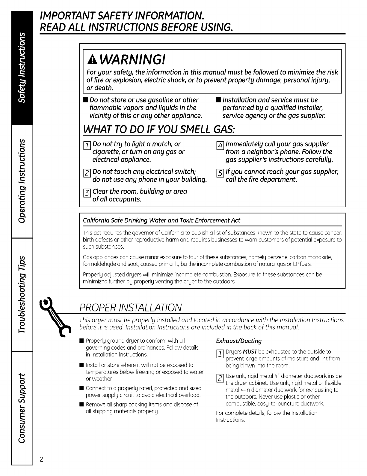
FOR YOUR SAFETY:
_aWA RNING- .is,o,Fire
• To reduce the risk of severe injury or death, follow
all installation instructions.
• Clothes dryer installation must be performed by a
qualified installer.
• Install the clothes dryer according to these
instructions and in accordance with local codes.
This dryer must be exhausted to the outdoors.
Use only 4" rigid metal ducting for exhausting the
clothes dryer to the outdoors.
DO NOT install a clothes dryer with flexible plastic
ducting materials. If flexible metal (semi-rigid or
foil-type) duct is installed, it must be UL-listed and
installed in accordance with the instructions found
in "Connecting the Dryer to House Vent" on page 26
of this manual. Flexible ducting materials are known
to collapse, be easily crushed and trap lint. These
conditions will obstruct dryer airflow and increase
the risk of fire.
• Do not install or store this appliance in any location
where it could be exposed to water and/or weather.
• Save these instructions. (Installers: Be sure to leave
these instructions with the customer.)
FOR GAS MODELS ONLY:
NOTE: Installation and service of this dryer must be
performed bg a qualified installer, service agency or
the gas supplier.
In the Commonwealth of Massachusetts:
• This product must be installed bg a licensed
plumber or gas fitter.
• When using ball-type gas shut-off valves, they
shall be T-handle-type.
• A flexible gas connector, when used, must not
exceed 3 feet.
UPVH890
I
14
Installation Instructions
UNPACKING YOUR DRYER
Tilt the dryer sideways and remove the foam
shipping pads by pulling at the sides and breaking
them away from the dryer legs. Be sure to remove
all of the foam pieces around the legs.
Remove the bag containing the literature and serial
cable.
LOCATION OF YOUR DRYER
MINIMUM CLEARANCE OTHER THAN
ALCOVE OR CLOSET INSTALLATION
Minimum clearance to combustible surfaces and
for air openings are:
• 0 inch clearance both sides
• 1 inch front
• 3 inches rear
Consideration must be given to provide adequate
clearance for proper operation and service.
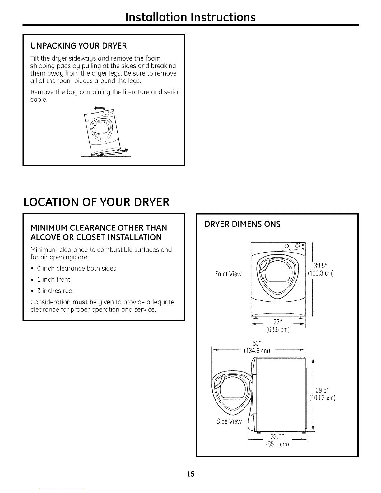
DRYER DIMENSIONS
FrontView
f _
(68.6cm)
53 _'
'_ (134.6cm)
oO_ 8: o
27"
oooo o
T
39.5"
(100.3 cm)
39.5"
(100.3cm)
Side View
33.5" __,,,
(85.1 cm)
15
Instollotion Instructions
REQUIREMENTS FOR ALCOVE OR
CLOSET INSTALLATION
• Your dryer is approved for installation in
an alcove or closet, as stated on a label on
the dryer back.
• The dryer MUST be vented to the outdoors. See
the EXHAUSTING THE DRYERsection.
• Minimum clearance between dryer cabinet and
adjacent walls or other surfaces is:
0" either side
::3"front and rear
• Minimum vertical space from floor to overhead
shelves, cabinets, ceilings, etc., is 52".
• Closet doors must be Iouvered or otherwise
ventilated and have at least 60 square inches
of open area equally distributed. If the closet
contains both a washer and a dryer, doors must
contain a minimum of 120 square inches of open
area equally distributed.
• The closet should be vented to the outdoors
to prevent gas pocketing in case of gas in the
supply line.
• No other fuel-burning appliance shall be
installed in the same closet with the dryer
(gas models only).
NOTE: WHEN THE EXHAUST DUCT IS LOCATEDAT
THE REAROF THE DRYER, MINIMUM CLEARANCE
FROM THE WALL IS 5.5 INCHES.
BATHROOM OR BEDROOM
INSTALLATION
• The dryer MUST be vented to the outdoors. See
EXHAUSTING THE DRYER.
• The installation must conform with local codes or,
in the absence of local codes, with the NATIONAL
ELECTRICALCODE, ANSI/NFPA NO. 70 (for electric
dryers) or NATIONAL FUEL GASCODE, ANSI Z223
(for gas dryers).
MOBILE OR MANUFACTURED HOME
INSTALLATION
• The installation must conform to the
MANUFACTURED HOME CONSTRUCTION & SAFETY
STANDARD, TITLE 24, PART:32-80 or, when such
standard is not applicable, with AMERICAN
NATIONAL STANDARD FORMOBILE HOME,
NO. 50lB.
• The dryer MUST be vented to the outdoors with
the termination securely fastened to the mobile
home structure. (See EXHAUSTING THE DRYER.)
• The vent MUST NOT be terminoted beneoth o
mobile or manufactured home.
• The vent duct moteriol MUST BEMETAL.
• FOR GAS MODELS ONLY:KIT 14-D346-33 MUST be
used to ottoch the dryer securely to the structure.
• FOR GAS MODELS ONLY:The vent MUST NOT be
connected to any other duct, vent or chimney.
• Do not use sheet metol screws or other
refustening devices which extend into the interior
of the exhaust vent.
• Provide an opening with u free urea of at least
25 sq. in. for introduction of outside air into the
dryer room.
16
Installation Instructions
CONNECTING INLET HOSES
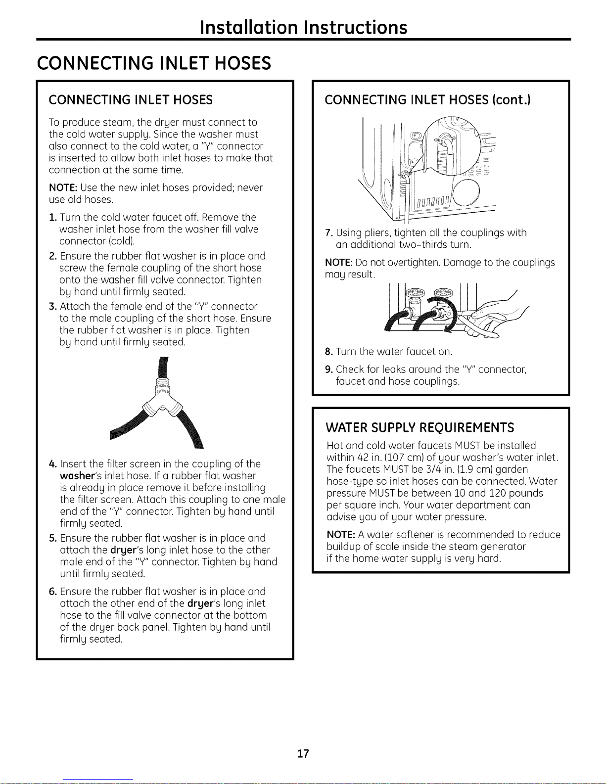
CONNECTING INLET HOSES
To produce steam, the dryer must connect to
the cold water supply. Since the washer must
also connect to the cold water, a "Y" connector
is inserted to allow both inlet hoses to make that
connection at the same time.
NOTE: Use the new inlet hoses provided; never
use old hoses.
, Turn the cold water faucet off. Remove the
washer inlet hose from the washer fill valve
connector (cold).
2. Ensure the rubber flat washer is in place and
screw the female coupling of the short hose
onto the washer fill valve connector. Tighten
by hand until firmly seated.
3. Attach the female end of the "Y" connector
to the male coupling of the short hose. Ensure
the rubber flat washer is in place. Tighten
by hand until firmly seated.
CONNECTING INLET HOSES {cont.}
7. Using pliers, tighten all the couplings with
an additional two-thirds turn.
NOTE: Do not overtighten. Damage to the couplings
may result.
8. Turn the water faucet on.
9. Check for leaks around the "Y" connector,
faucet and hose couplings.
4. Insert the filter screen in the coupling of the
washer's inlet hose. If a rubber flat washer
is already in place remove it before installing
the filter screen. Attach this coupling to one male
end of the "Y" connector. Tighten by hand until
firmly seated.
5. Ensure the rubber flat washer is in place and
attach the dryer's long inlet hose to the other
male end of the "Y" connector. Tighten by hand
until firmly seated.
,
Ensure the rubber flat washer is in place and
attach the other end of the dryer's long inlet
hose to the fill valve connector at the bottom
of the dryer back panel. Tighten by hand until
firmly seated.
WATER SUPPLY REQUIREMENTS
Hot and cold water faucets MUST be installed
within/42 in. (107 cm) of your washer's water inlet.
The faucets MUST be ::3//4in. (1.9 cm) garden
hose-type so inlet hoses can be connected. Water
pressure MUST be between 10 and 120 pounds
per square inch. Your water department can
advise you of your water pressure.
NOTE: A water softener is recommended to reduce
buildup of scale inside the steam generator
if the home water supply is very hard.
17
Installation Instructions
CONNECTING A GAS DRYER(skip for electric dryers)
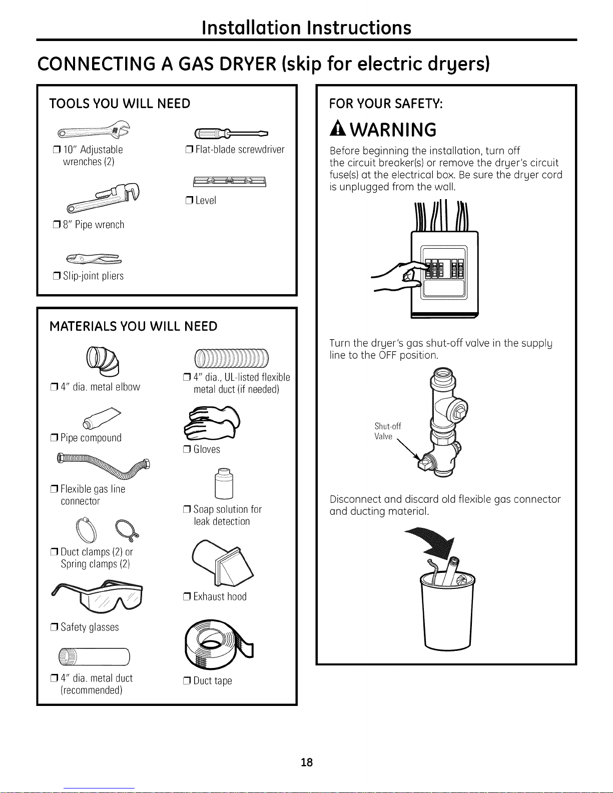
TOOLS YOU WILL NEED
[] 10" Adjustable
wrenches (2)
[] 8" Pipewrench
[] Slip-joint pliers
[] Flat-blade screwdriver
[] Level
MATERIALS YOU WILL NEED
%
[] 4" dia. metal elbow
[] 4" dia.,UL-listedflexible
metal duct(if needed)
FOR YOUR SAFETY:
-AWARNING
Before beginning the installation, turn off
the circuit breaker(s) or remove the dryer's circuit
fuse(s) at the electrical box. Be sure the dryer cord
is unplugged from the wall.
Turn the dryer's gas shut-off valve in the supply
line to the OFF position.
[] Pipecompound
[] Flexible gas line
connector
%
[] Duct clamps(2) or
Spring clamps (2)
[] Safety glasses
[] 4" dia. metal duct
(recommended)
[] Gloves
[] Soap solution for
leakdetection
[] Exhaust hood
[] Duct tape
Shut-off
Valve
Disconnect and discard old flexible gas connector
and ducting material.
18
Installation Instructions
GAS REQUIREMENTS
-AWARNING
Installation must conform to local codes
and ordinances, or in their absence, the
NATIONAL FUEL GAS CODE, ANSI Z223.
• This gas dryer is equipped with a Valve and
Burner Assembly for use only with natural gas.
Using conversion kit ]_4-A048, your local service
organization can convert this dryer for use with
propane (LP)gas. ALL CONVERSIONS MUST BE
MADE BY PROPERLYTRAINED AND QUALIFIED
PERSONNEL AND IN ACCORDANCE WITH LOCAL
CODES AND ORDINANCE REQUIREMENTS.
• The dryer must be disconnected from the gas
supply piping system during any pressure testing
of that system at a test pressure in excess of
0.5 PSi (3.4 KPa).
The dryer must be isolated from the gas supply
piping system by closing the equipment shut-off
valve during any pressure testing of the gas
supply piping of test pressure equal to or less
than 0.5 PSi (3.4KPa).
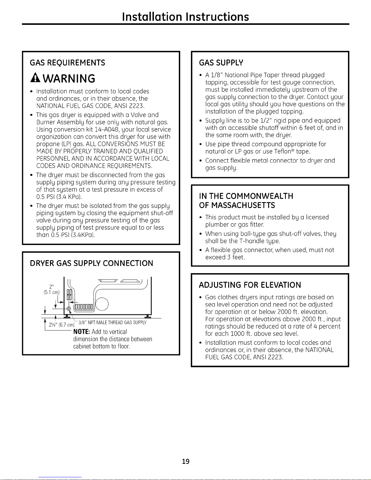
DRYER GAS SUPPLY CONNECTION
GAS SUPPLY
• A 1/8" National Pipe Taper thread plugged
tapping, accessible for test gauge connection,
must be installed immediately upstream of the
gas supply connection to the dryer. Contact your
local gas utility should you have questions on the
installation of the plugged tapping.
• Supply line is to be 1/2" rigid pipe and equipped
with an accessible shutoff within 6 feet of, and in
the same room with, the dryer.
• Use pipe thread compound appropriate for
natural or LP gas or use Teflon ®tape.
• Connect flexible metal connector to dryer and
gas supply.
IN THE COMMONWEALTH
OF MASSACHUSETTS
• This product must be installed by a licensed
plumber or gas fitter.
• When using ball-type gas shut-off valves, they
shall be the T-handle type.
• A flexible gas connector, when used, must not
exceed 3 feet.
2- lu
2%' (6.7.cm) 3/8" NPTMALETHREADGASSUPPLY
/
NOTE: Add to vertical
dimension the distance between
cabinet bottom to floor.
ADJUSTING FOR ELEVATION
Gas clothes dryers input ratings are based on
sea level operation and need not be adjusted
for operation at or below 2000 ft. elevation.
For operation at elevations above 2000 ft., input
ratings should be reduced at a rate of/4 percent
for each 1OOOft. above sea level.
Installation must conform to local codes and
ordinances or, in their absence, the NATIONAL
FUEL GAS CODE, ANSI Z223.
19
Installation Instructions
CONNECTING A GAS DRYER (cont.)
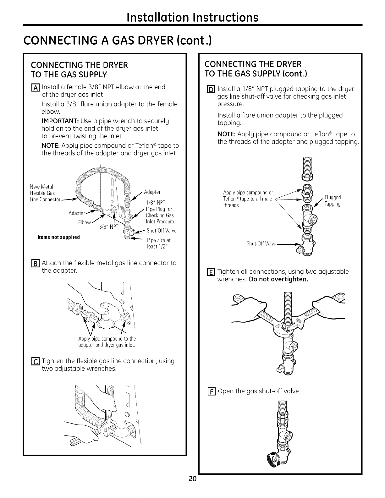
CONNECTING THE DRYER
TO THE GAS SUPPLY
Install a female 3/8" NPT elbow at the end
of the drger gas inlet.
Install a 3/8" flare union adapter to the female
elbow.
IMPORTANT: Use a pipe wrench to securelg
hold on to the end of the drger gas inlet
to prevent twisting the inlet.
NOTE: Applg pipe compound or Teflon ®tape to
the threads of the adapter and drger gas inlet.
NewMetal
FlexibleGas _ I ]I /Adapter
LineConnector___ I _ i "_ 1/8" NPT
Adapter [_1¢" Checking Gas
Elbow/ ix. _ Inlet Pressure
3/8" NPT i%_.. -- Shut-OffVave
Itemsnotsupplied _ Pipesizeat
least1/2"
CONNECTING THE DRYER
TO THE GAS SUPPLY (cont.)
@Install a 2/8" NPT plugged tapping to the dryer
gas line shut-off valve for checking gas inlet
pressure.
Install a flare union adapter to the plugged
tapping.
NOTE: Apply pipe compound or Teflon ® tape to
the threads of the adapter and plugged tapping.
Applypipecompoundor _w'_
Teflon®tape to all male N_---------b_'_ / Plugged
threads. _ _1¢ Tapping
Shut-OffValve__ !
IB1 Attach the flexible metal gas line connector to
the adapter.
Applypipecompoundtothe
adapteranddryergasinlet.
[] Tighten the flexible gas line connection, using
two adjustable wrenches.
' "4
_j
I-_ Tighten all connections, using two adjustable
wrenches. Do not overtighten.
[] Open the gas shut-off valve.
2O
Installation Instructions
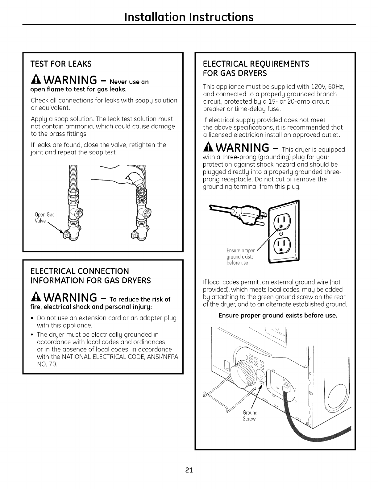
TEST FOR LEAKS
WARNING - Neverusean
open flame to test for gas leaks.
Check all connections for leaks with soapy solution
or equivalent.
Apply a soap solution. The leak test solution must
not contain ammonia, which could cause damage
to the brass fittings.
If leaks are found, close the valve, retighten the
joint and repeat the soap test.
OpenGas
Valve
ELECTRICAL REQUIREMENTS
FOR GAS DRYERS
This appliance must be supplied with 120V, 60Hz,
and connected to a properly grounded branch
circuit, protected by a 15- or 20-amp circuit
breaker or time-delay fuse.
If electrical supply provided does not meet
the above specifications, it is recommended that
a licensed electrician install an approved outlet.
WARNING - Thisdryerisequipped
witha three-prong(grounding)plugforyour
protectionagainstshock hazard and should be
plugged directlyintoa properlygrounded three-
prong receptacle.Do not cutor remove the
groundingterminalfrom thisplug.
ELECTRICAL CONNECTION
INFORMATION FOR GAS DRYERS
-A WARNING - Toreducetheriskof
fire, electrical shock and personal injury:
Do not use an extension cord or an adapter plug
with this appliance.
The dryer must be electrically grounded in
accordance with local codes and ordinances,
or in the absence of local codes, in accordance
with the NATIONAL ELECTRICALCODE, ANSI/NFPA
NO. 70.
Ensureproper
groundexists
beforeuse.
If local codes permit, an external ground wire (not
provided), which meets local codes, may be added
by attaching to the green ground screw on the rear
of the dryer, and to an alternate established ground.
Ensure proper ground exists before use.
Ground
Screw
21
Installation Instructions
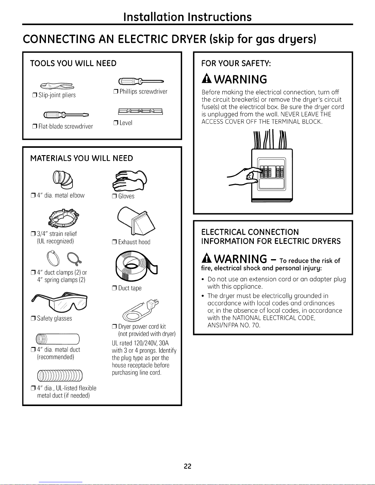
CONNECTING AN ELECTRICDRYER(skip for gas drgers)
TOOLS YOU WILL NEED
[] Slip-joint pliers
[] Flat-blade screwdriver
MATERIALS YOU WILL NEED
[] Phillips screwdriver
[] Level
%
[] 4" dia. metal elbow
[] 3/4" strain relief
(ULrecognized)
[] Gloves
[] Exhausthood
FOR YOUR SAFETY:
-AWARNING
Before making the electrical connection, turn off
the circuit breaker(s) or remove the dryer's circuit
fuse(s) at the electrical box. Be sure the dryer cord
is unplugged from the wall. NEVER LEAVETHE
ACCESSCOVER OFF THE TERMINAL BLOCK.
ELECTRICAL CONNECTION
INFORMATION FOR ELECTRIC DRYERS
%%
[] 4" duct clamps (2)or
4" spring clamps (2)
[] Safety glasses
)
[] 4" dia. metal duct
(recommended)
[] 4" dia., UL-listedflexible
metal duct (if needed)
[] Duct tape
[] Dryerpowercord kit
(notprovidedwith dryer)
ULrated 120/240V,30A
with 3 or 4 prongs.Identify
the plug type as perthe
housereceptaclebefore
purchasingline cord.
-A WARNING - Toreducetheriskof
fire, electrical shock and personal injury:
• Do not use an extension cord or an adapter plug
with this appliance.
• The dryer must be electrically grounded in
accordance with local codes and ordinances
or, in the absence of local codes, in accordance
with the NATIONAL ELECTRICALCODE,
ANSI/NFPA NO. 70.
22
Installation Instructions
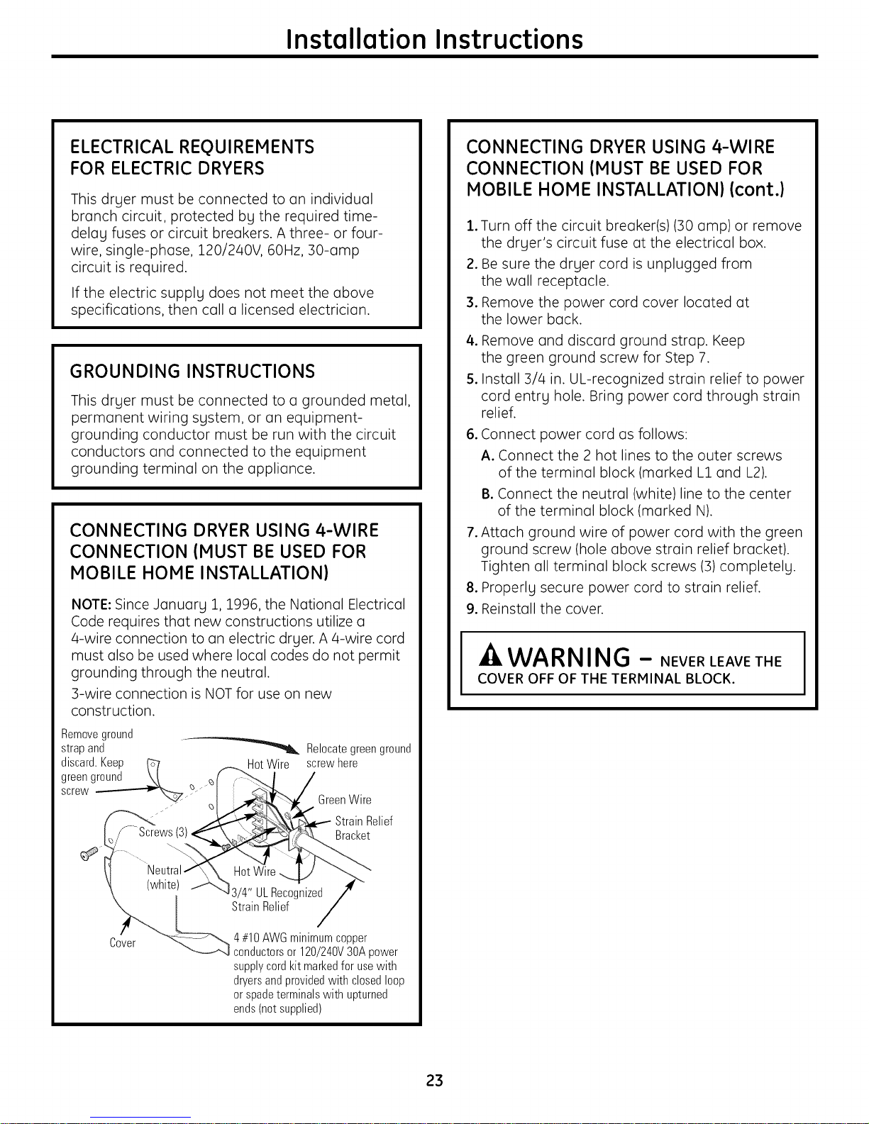
ELECTRICAL REQUIREMENTS
FOR ELECTRIC DRYERS
This dryer must be connected to an individual
branch circuit, protected by the required time-
delay fuses or circuit breakers. A three- or four-
wire, single-phase, 120/240V, 60Hz, 30-amp
circuit is required.
If the electric supply does not meet the above
specifications, then call a licensed electrician.
GROUNDING INSTRUCTIONS
This dryer must be connected to a grounded metal,
permanent wiring system, or an equipment-
grounding conductor must be run with the circuit
conductors and connected to the equipment
grounding terminal on the appliance.
CONNECTING DRYER USING 4-WIRE
CONNECTION (MUST BE USED FOR
MOBILE HOME INSTALLATION}
NOTE: Since January 1, 1996, the National Electrical
Code requires that new constructions utilize a
a-wire connection to an electric dryer. A 4-wire cord
must also be used where local codes do not permit
grounding through the neutral.
3-wire connection is NOT for use on new
construction.
Removeground
strap and "_ Relocate green ground
discard.Keep _7 HotWire screwhere
greenground \/ _f J_.. I /
CONNECTING DRYER USING 4-WIRE
CONNECTION (MUST BE USED FOR
MOBILE HOME INSTALLATION} (cont.}
.
Turn off the circuit breaker(s)(30 amp) or remove
the dryer's circuit fuse at the electrical box.
2.
Be sure the dryer cord is unplugged from
the wall receptacle.
3.
Remove the power cord cover located at
the lower back.
4.
Remove and discard ground strap. Keep
the green ground screw for Step 7.
5.
Install 3/4 in. UL-recognized strain relief to power
cord entry hole. Bring power cord through strain
relief.
.
Connect power cord as follows:
A. Connect the 2 hot lines to the outer screws
of the terminal block (marked L1 and L2).
B.Connect the neutral (white)line to the center
of the terminal block (marked N).
.
Attach ground wire of power cord with the green
ground screw (hole above strain relief bracket).
Tighten all terminal block screws (3) completely.
.
Properly secure power cord to strain relief.
9.
Reinstall the cover.
WARNING - NEVERLEAVETHE
COVER OFF OF THE TERMINAL BLOCK.
screw __ GreenWire
_ __\\_\P-_d-. _ StrainRelief
I_/ Screws(3)_:_X__£._ Bracket
(white_ UL Reco_ized /"
_ [ ..... StrainRelief /
" "_--_ 4#10 AWGminimumcopper
_cver _'_-----.A_ conductorsor 120/240V30Apower
supplycordkit markedfor usewith
dryersandprovidedwith closedloop
or spadeterminalswith upturned
ends(net supplied)
23
Installation Instructions
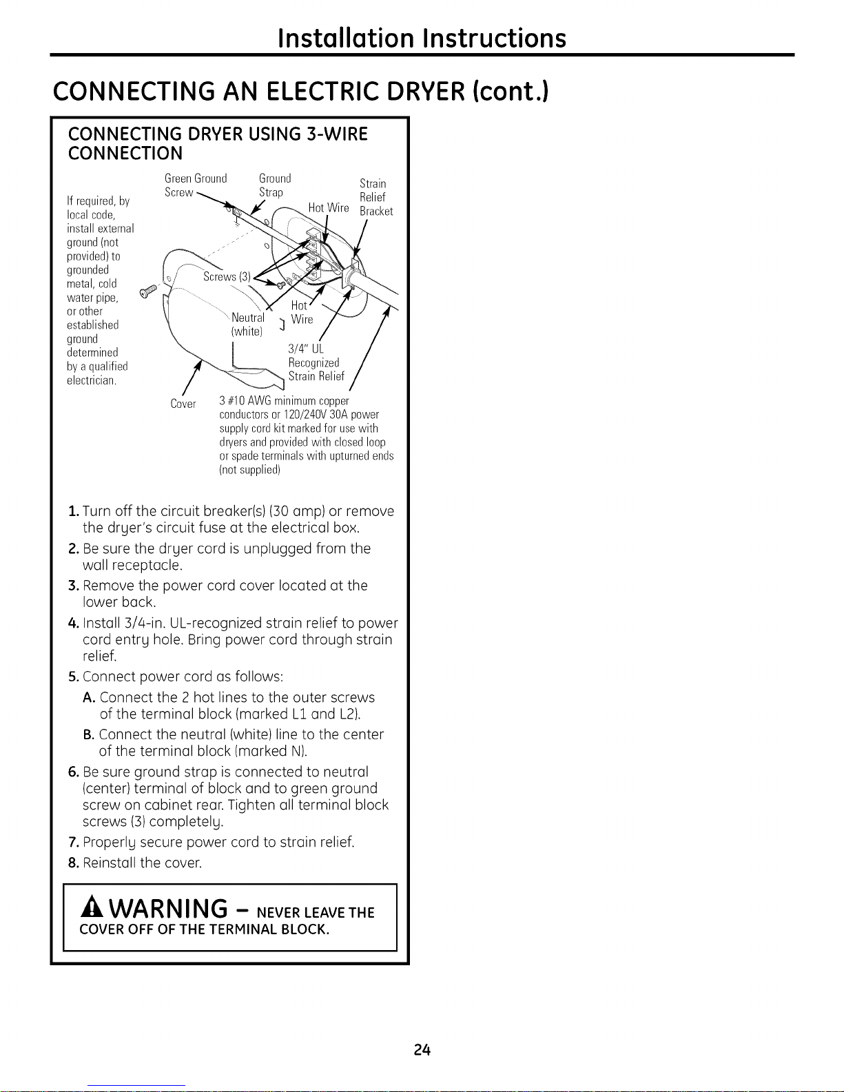
CONNECTING AN ELECTRICDRYER(cont.)
CONNECTING DRYER USING 3-WIRE
CONNECTION
GreenGround Ground Strain
Ifrequired,by
localcode,
installexternal
ground(not
provided)to
grounded
metal,cold
water pipe,
or other
established
ground
determined
byaqualified
electrician.
Screw Strap Relief
HotWire Bracket
Screws
.Neutral Wire
(white) ]
3/4" UL
Recognized
StrainRelief
Cover
3#10AWGminimumcopper
conductorsor 120/240V3OApower
supplycordkit markedfor usewith
dryersandprovidedwith closedloop
or spadeterminalswith upturnedends
(notsupplied)
1.Turn off the circuit breaker(s)(30 amp) or remove
the dryer's circuit fuse at the electrical box.
2. Be sure the dryer cord is unplugged from the
wall receptacle.
3. Remove the power cord cover located at the
lower back.
4. Install 3/4-in. UL-recognized strain relief to power
cord entrg hole. Bring power cord through strain
relief.
5. Connect power cord as follows:
A. Connect the 2 hot lines to the outer screws
of the terminal block (marked L1 and L2).
B.Connect the neutral (white)line to the center
of the terminal block (marked N).
6. Be sure ground strap is connected to neutral
(center) terminal of block and to green ground
screw on cabinet rear. Tighten all terminal block
screws (3) completely.
7. Properly secure power cord to strain relief.
8. Reinstall the cover.
WARNING - NEVERLEAVETHE
COVER OFF OF THE TERMINAL BLOCK.
24

Installation Instructions
EXHAUSTING THE DRYER
-A WARNING - Toreducethe
risk of fire or personal injury:
• This clothes dryer must be exhausted to the outdoors.
• Use only 4" rigid metal ducting for the home
exhaust duct.
• Use only 4" rigid metal or UL-listed flexible metal
(semi-rigid or foil-type) duct to connect the dryer
to the home exhaust duct. It must be installed
in accordance with the instructions found in
"Connecting the Dryer to House Vent" on page 26
of this manual.
• Do not terminate exhaust in a chimney, a wall, a
ceiling, gas vent, crawl space, attic, under an
enclosed floor, or in any other concealed space of
a building.
• Never terminate the exhaust into a common duct
with a kitchen exhaust system. A combination of
grease and lint creates a potential fire hazard.
• Do not use duct longer than specified in the exhaust
length table. Longer ducts can accumulate lint,
creating a potential fire hazard.
• Never install a screen in or over the exhaust duct.
This will cause lint to accumulate, creating a
potential fire hazard.
• Do not assemble ductwork with any fasteners that
extend into the duct. These fasteners can
accumulate lint, creating a potential fire hazard.
• Do not obstruct incoming or exhausted air.
• Provide an access for inspection and cleaning of
the exhaust system, especially at turns and joints.
Exhaust system shall be inspected and cleaned at
least once a year.
• This dryer comes ready for rear exhausting. Ifspace
is limited, use the instructions on pages 29-:31 to
exhaust directly from the sides or bottom of the
cabinet.
EXHAUST SYSTEM CHECKLIST
HOOD OR WALL CAP
• Terminate in a manner to prevent back drafts or
entry of birds or other wildlife.
• Termination should present minimal resistance to
the exhaust airflow and should require little or no
maintenance to prevent clogging.
• Never install a screen in or over the exhaust duct.
• Wall caps must be installed at least 12" above
ground level or any other obstruction with the
opening pointed down.
SEPARATIONOF TURNS
• For best performance, separate all turns by
at least 4 ft. of straight duct, including distance
between last turn and dampened wall cap.
SEALING OF JOINTS
• All joints should be tight to avoid leaks. The male
end of each section of duct must point away
from the dryer.
• Do not assemble the ductwork with fasteners that
extend into the duct. They will serve as a collection
point for lint.
• Duct joints should be made air- and moisture-tight
by wrapping the overlapped joints with duct tape
or aluminum tape.
• Horizontal runs should slope down towards the
outdoors 1/4" per foot.
INSULATION
• Ductwork that runs through an unheated area
or is near air conditioning should be insulated
to reduce condensation and lint buildup.
TOOLS AND MATERIALS YOU WILL
NEED TO INSTALL EXHAUST DUCT
[] Phillips-head screwdriver
[] Drill with 1/8" drill bit
(for bottom venting)
[] Duct tape or duct clamp
[] Hacksaw
1)
[] Rigid or UL-listedflexible
metal 4" (10.2cm)duct
[] Vent hood
25
Installation Instructions
EXHAUSTING THE DRYER (cont.)
CONNECTING THE DRYER TO
HOUSE VENT
RIGID METALTRANSITION DUCT
• For best drying performance, a rigid metal
transition duct is recommended.
• Rigid metal transition ducts reduce the risk of
crushing and kinking.
UL-LISTED FLEXIBLEMETAL (SEMI-RIGID)
TRANSITION DUCT
• If rigid metal duct cannot be used, then ULdisted
flexible metal (semi-rigid)ducting can be used
(Kit WX08X10077).
• Never install flexible metal duct in walls, ceilings,
floors or other enclosed spaces.
• Total length of flexible metal duct should not
exceed 8 feet (2.4 m).
• For many applications, installing elbows at both
the dryer and the wall is highly recommended (see
illustrations at right). Elbows allow the dryer to sit
close to the wall without kinking and/or crushing
the transition duct, maximizing drying performance.
• Avoid resting the duct on sharp objects.
UL-LISTED FLEXIBLEMETAL (FOIL-TYPE)
TRANSITION DUCT
In special installations, it may be necessary to
connect the dryer to the house vent using a flexible
metal (foil-type)duct. A UL-listed flexible metal
(foil-type) duct may be used ONLYin installations
where rigid metal or flexible metal (semi-rigid)
ducting cannot be used AND where a 4" diameter
can be maintained throughout the entire length
of the transition duct.
In Canada and the United States, only the flexible
metal (foil-type) ducts that comply with the "Outline
for Clothes Dryer Transition Duct Subject 2158A"
shall be used.
Never install flexible metal duct in walls, ceilings,
floors or other enclosed spaces.
Total length of flexible metal duct should not
exceed 8 feet (2.4 m).
Avoid resting the duct on sharp objects.
For best drying performance:
1.Slide one end of the duct over the clothes
dryer outlet pipe.
2. Secure the duct with a clamp.
3. With the dryer in its permanent position,
extend the duct to its full length. Allow 2" of
duct to overlap the exhaust pipe. Cut off and
remove excess duct. Keep the duct as straight
as possible for maximum airflow.
4. Secure the duct to the exhaust pipe with the
other clamp.
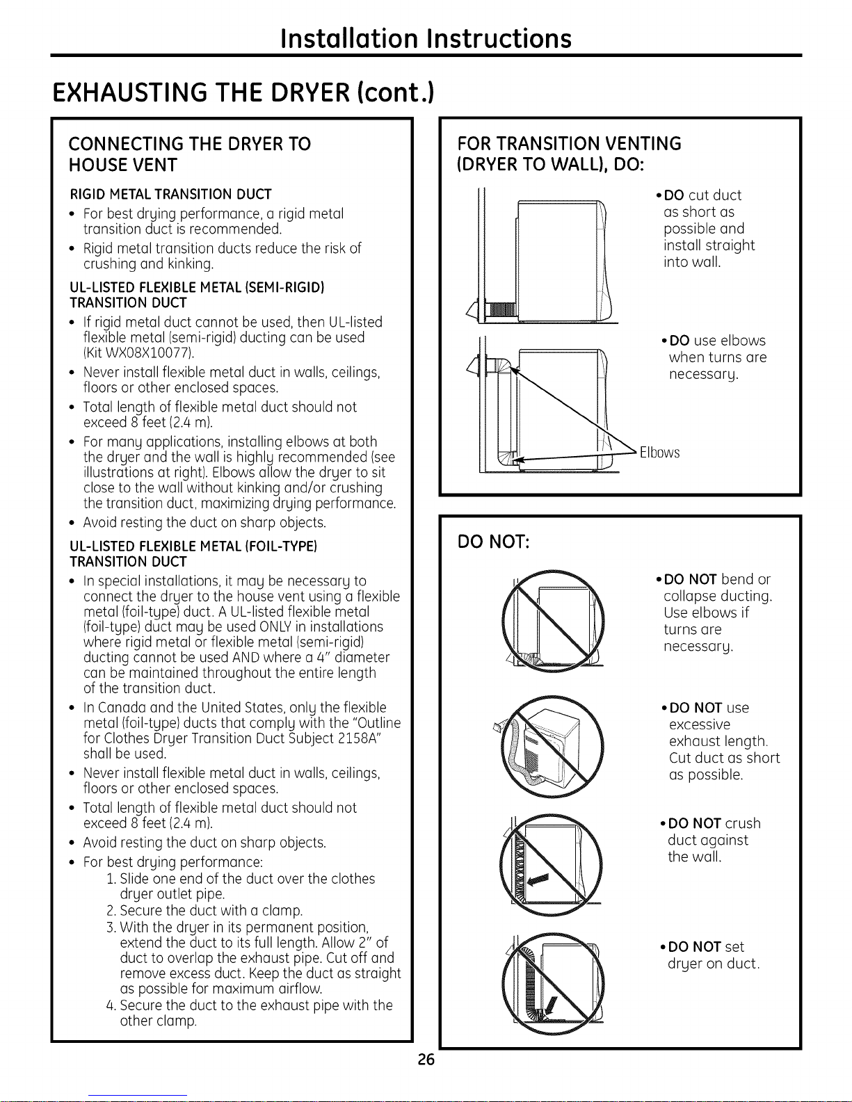
FOR TRANSITION VENTING
(DRYER TO WALL}, DO:
• DO cut duct
DO NOT:
• DO NOT bend or
'@
@
@
@
as short as
possible and
install straight
into wall.
• DO use elbows
when turns are
necessary.
collapse ducting.
Use elbows if
turns are
necessary.
• DO NOT use
excessive
exhaust length.
Cut duct as short
as possible.
•DO NOT crush
duct against
the wall.
• DO NOT set
dryer on duct.
26
Installation Instructions
-A WARNING - USEONLYMETAL
4" DUCT. DO NOT USE DUCT LONGER THAN
SPECIFIED IN THE EXHAUST LENGTH TABLE.
Using exhaust longer than specified length will:
• Increase the drging times and the energg cost.
• Reduce the drger life.
• Accumulate lint, creating a potential
fire hazard.
The correct exhaust installation is YOUR
RESPONSIBILITY.
Problems due to incorrect installation
are not covered bg the warrantg.
EXHAUST SYSTEM CHECKLIST
HOOD OR WALL CAP
• Terminate in a manner to prevent back drafts
or entry of birds or other wildlife.
• Termination should present minimal resistance
to the exhaust airflow and should require little
or no maintenance to prevent clogging.
• Never install a screen in or over the exhaust
duct. This could cause lint buildup.
• Wall caps must be installed at least 12" above
ground level or ang other obstruction with the
opening pointed down.
SEPARATION OF TURNS
The MAXIMUM ALLOWABLE length of
the exhaust sgstem depends upon the tgpe
of duct, number of turns, the tgpe of exhaust
hood (wall cap) and all conditions noted below.
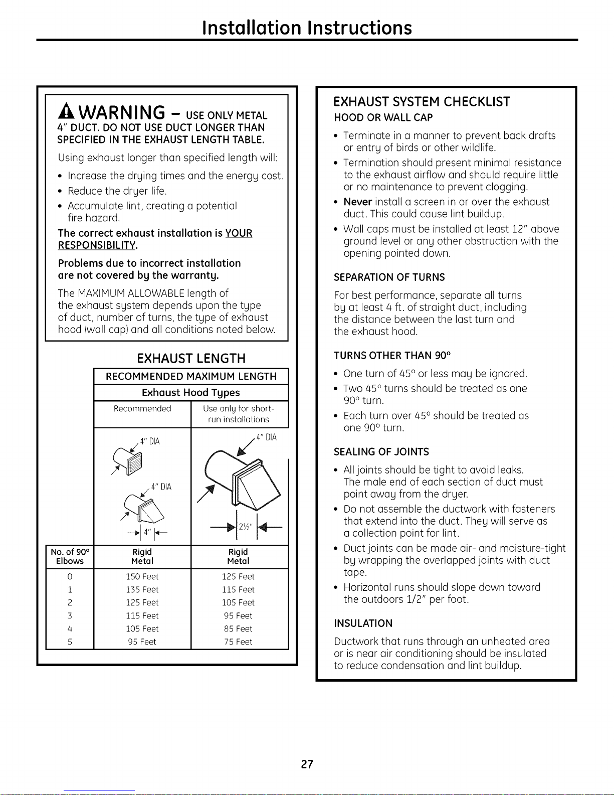
EXHAUST LENGTH
RECOMMENDED MAXIMUM LENGTH
Exhaust Hood Types
Recommended Use onlg for short-
run installations
4" DIA
_. 4" DIA
-_ 4" I_---
No. of 90°
Elbows
0
1
2
3
4
5
Rigid
Metal
150 Feet
135 Feet
125 Feet
115 Feet
105 Feet
95 Feet
Rigid
Metal
125 Feet
115 Feet
105 Feet
95 Feet
85 Feet
75 Feet
4" DIA
For best performance, separate all turns
bg at least/4 ft. of straight duct, including
the distance between the last turn and
the exhaust hood.
TURNS OTHER THAN 90 °
• One turn of 45 ° or less may be ignored.
• Two 45 ° turns should be treated as one
90 ° turn.
• Each turn over 45 ° should be treated as
one 90° turn.
SEALING OF JOINTS
• All joints should be tight to avoid leaks.
The male end of each section of duct must
point awag from the drger.
• Do not assemble the ductwork with fasteners
that extend into the duct. Theg will serve as
a collection point for lint.
• Duct joints can be made air- and moisture-tight
bg wrapping the overlapped joints with duct
tape.
• Horizontal runs should slope down toward
the outdoors 1/2" per foot.
INSULATION
Ductwork that runs through an unheated area
or is near air conditioning should be insulated
to reduce condensation and lint buildup.
27
Installation Instructions
EXHAUSTING THE DRYER (cont.)
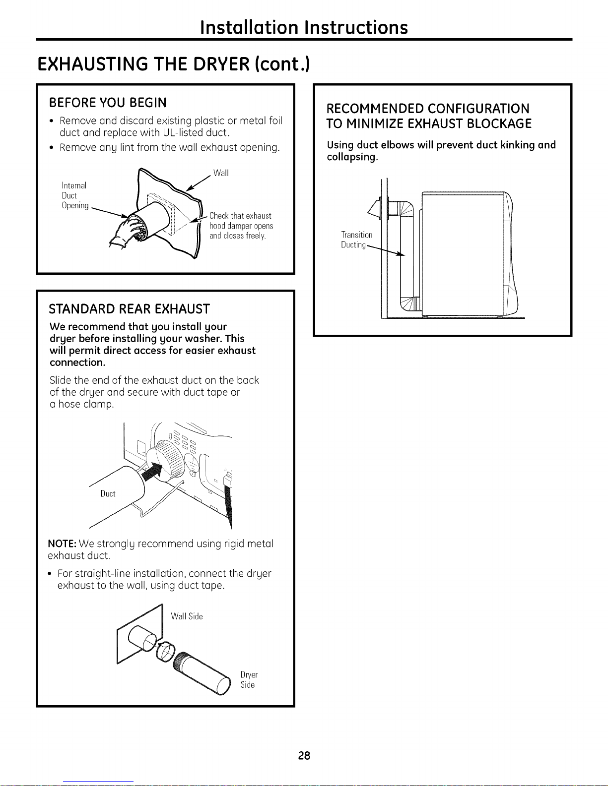
BEFORE YOU BEGIN
• Remove and discard existing plastic or metal foil
duct and replace with UL-listed duct.
• Remove ang lint from the wall exhaust opening.
Wall
Internal
Duct
Opening
"__ Checkthat exhaust
and closes freely.
hooddamperopens
STANDARD REAR EXHAUST
We recommend that gou install gour
drger before installing gour washer. This
will permit direct access for easier exhaust
connection.
Slide the end of the exhaust duct on the back
of the druer and secure with duct tape or
a hose clamp.
RECOMMENDED CONFIGURATION
TO MINIMIZE EXHAUST BLOCKAGE
Using duct elbows will prevent duct kinking and
collapsing.
Transition
Ducting_
Duct
NOTE: We strongly recommend using rigid metal
exhaust duct.
• For straight-line installation, connect the dryer
exhaust to the wall, using duct tape.
Dryer
Side
28
Installation Instructions
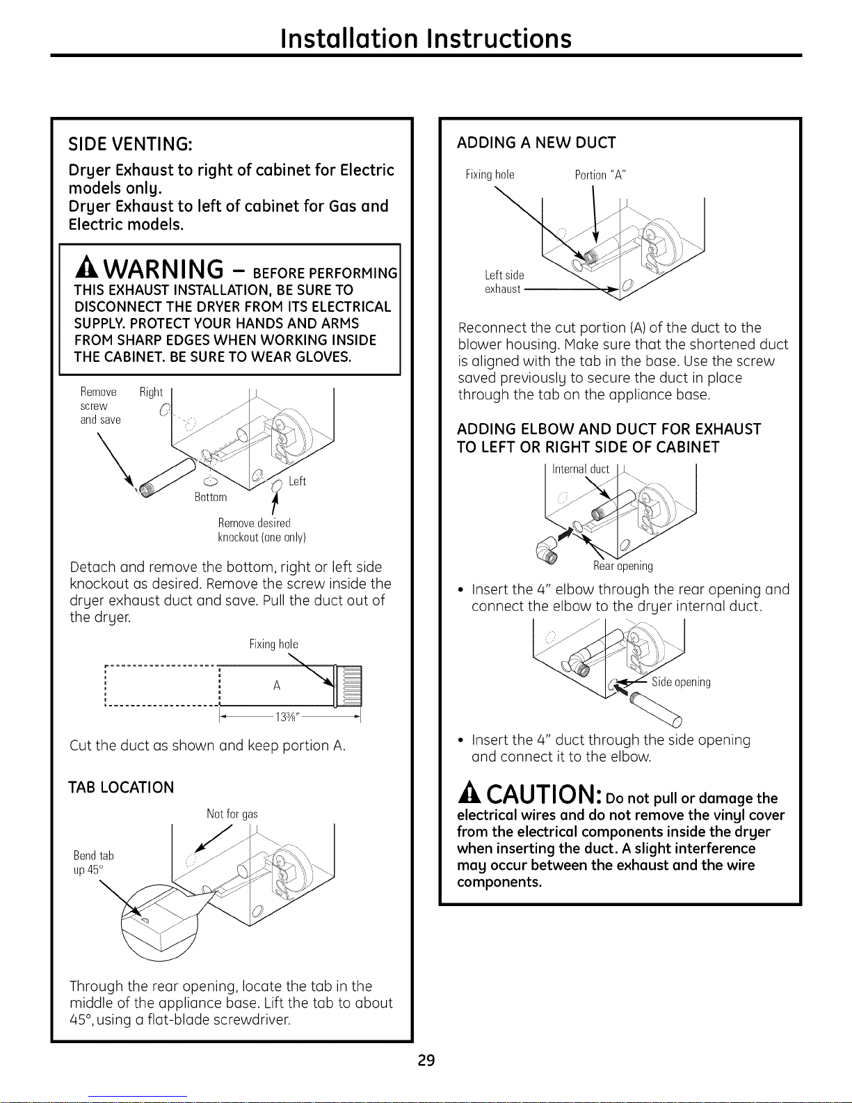
SIDE VENTING:
Dryer Exhaust to right of cabinet for Electric
models only.
Dryer Exhaust to left of cabinet for Gas and
Electric models.
-A WARNING - BEFOREPERFORMING
THIS EXHAUST INSTALLATION, BE SURE TO
DISCONNECT THE DRYER FROM ITS ELECTRICAL
SUPPLY. PROTECT YOUR HANDS AND ARMS
FROM SHARP EDGES WHEN WORKING INSIDE
THE CABINET. BE SURE TO WEAR GLOVES.
Remove
screw
and save
Right
Left
Bottom
Removedesired
knockout(oneonly)
ADDING A NEW DUCT
Fixinghole Portion"A"
Reconnect the cut portion (A)of the duct to the
blower housing. Make sure that the shortened duct
is aligned with the tab in the base. Use the screw
saved previously to secure the duct in place
through the tab on the appliance base.
ADDING ELBOW AND DUCT FOR EXHAUST
TO LEFT OR RIGHT SIDE OF CABINET
Internalduct
Detach and remove the bottom, right or left side
knockout as desired. Remove the screw inside the
dryer exhaust duct and save. Pull the duct out of
the dryer.
Fixinghole
Cut the duct as shown and keep portion A.
TAB LOCATION
Notfor gas
Bendtab
up45°
Rear opening
• Insert the 4" elbow through the rear opening and
connect the elbow to the dryer internal duct.
Sideopening
• Insert the 4" duct through the side opening
and connect it to the elbow.
-A CAUTION: Do not pull or damage the
electrical wires end do not remove the vingl cover
from the electrical components inside the drger
when inserting the duct. A slight interference
meg occur between the exhaust end the wire
components.
Through the rear opening, locate the tab in the
middle of the appliance base. Lift the tab to about
/45°, using a flat-blade screwdriver.
29
Installation Instructions
EXHAUSTING THE DRYER (cont.)
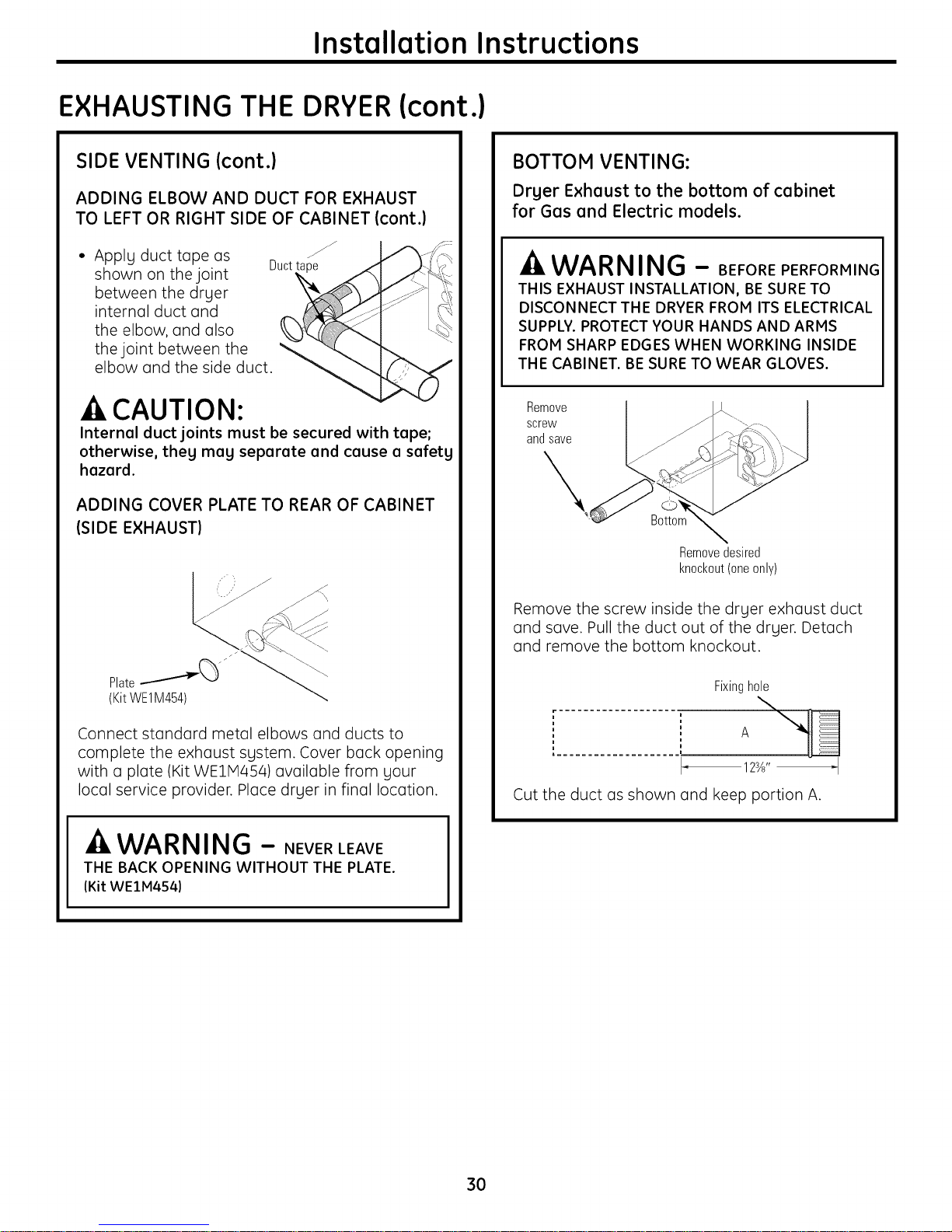
SIDE VENTING (cont.)
ADDING ELBOW AND DUCT FOR EXHAUST
TO LEFT OR RIGHT SIDE OF CABINET (cont.)
• Apply duct tape as
shown on the joint
between the dryer
internal duct and
the elbow, and also
the joint between the "
elbow and the side duct.
Duct
-ACAUTION:
Internal duct joints must be secured with tape;
otherwise, they may separate and cause a safety
hazard.
ADDING COVER PLATE TO REAR OF CABINET
(SIDE EXHAUST)
BOTTOM VENTING:
Drger Exhaust to the bottom of cabinet
for Gas and Electric models.
WARNING - BEFOREPERFORMING
THIS EXHAUST INSTALLATION, BE SURE TO
DISCONNECT THE DRYER FROM ITS ELECTRICAL
SUPPLY. PROTECT YOUR HANDS AND ARMS
FROM SHARP EDGES WHEN WORKING INSIDE
THE CABINET. BE SURE TO WEAR GLOVES.
Remove
screw
and save
Bottom
Removedesired
knockout(oneonly)
Remove the screw inside the dryer exhaust duct
and save. Pull the duct out of the dryer. Detach
and remove the bottom knockout.
Connect standard metal elbows and ducts to
complete the exhaust system. Cover back opening
with a plate (Kit WEllVl4S4) available from your
local service provider. Place dryer in final location.
WAR NING - NEVERLEAVE
THE BACK OPENING WITHOUT THE PLATE.
(Kit WEIM454)
Fixinghole
123_'' _1
Cut the duct as shown and keep portion A.
3O
 Loading...