

Page 1
C
GE Consumer Home Services Training
TECHNICAL SERVICE GUIDE
Profile Stainless Steel
Gas and Electric Dryers
MODEL SERIES:
DPSB650
DPSB620
PUB # 31-9096 10/02
Page 2

!
IMPORTANT SAFETY NOTICE
The information in this service guide is intended for use by
individuals possessing adequate backgrounds of electrical,
electronic, and mechanical experience. Any attempt to repair a
major appliance may result in personal injury and property
damage. The manufacturer or seller cannot be responsible for the
interpretation of this information, nor can it assume any liability in
connection with its use.
WARNING
If the information in this manual is not followed exactly, a fire or
explosion may result causing proper ty damage, personal injury or
death. If you smell gas:
- Do not try to light any appliance.
- Do not touch any electrical switch; do not use any phone in
the building.
- Immediately call the gas supplier from a neighbor’s phone.
Follow the gas supplier’s instructions.
- If you cannot reach the gas supplier , call the fire department.
WARNING
To avoid personal injury, disconnect power before servicing this
product. If electrical power is required for diagnosis or test
purposes, disconnect the power immediately after performing the
necessary checks.
RECONNECT ALL GROUNDING DEVICES
If grounding wires, screws, straps, clips, nuts, or washers used
to complete a path to ground are removed for ser vice, they must
be returned to their original position and properly fastened.
GE Consumer Home Services Training
Technical Service Guide
Copyright © 2002
All rights reserved. This service guide may not be reproduced in whole or in part
in any form without written permission from the General Electric Company.
Page 3

T able of Contents
Airflow.............................................................................................................................. 22
Belt Switch ......................................................................................................................19
Belt, Drive........................................................................................................................19
Component Locator Views.............................................................................................. 14
Control Drying Cycles ..................................................................................................... 10
Control Dryness Levels................................................................................................... 10
Control Easy Touch Selections .........................................................................................8
Control Features ............................................................................................................... 4
Control Heat Settings ...................................................................................................... 11
Control Panel...................................................................................................................16
Control Quick Start Cycles................................................................................................ 6
Cycle Chart .....................................................................................................................13
Cycle Options.................................................................................................................. 12
Cycle Status ....................................................................................................................12
Door Switch ....................................................................................................................17
Drum ...............................................................................................................................17
Drum Shaft Bearing ........................................................................................................18
Drum Slide Assembly...................................................................................................... 18
Dryer Components..........................................................................................................16
Electronic Control Board ................................................................................................. 28
Error Codes ....................................................................................................................34
Front Panel......................................................................................................................16
Gas V a lv e ........................................................................................................................ 23
Glo-Bar Igniter Circuit Operation ..................................................................................... 24
Heater Assembly (Electric Models) ................................................................................. 23
Light, Drum .....................................................................................................................17
Motor and Blower Wheel ................................................................................................. 20
Nomenclature....................................................................................................................2
Schematic.......................................................................................................................42
Sensor Rods ................................................................................................................... 27
Serial Number ...................................................................................................................2
Service Mode................................................................................................................... 30
T emperature Setpoint Charts .......................................................................................... 29
Thermistor , Inlet............................................................................................................... 25
Thermistor , Outlet ........................................................................................................... 26
Thermostat, Hi-Limit (Electric Models)............................................................................27
Thermostat, Inlet Safety .................................................................................................. 25
Thermostat, Outlet Control Backup................................................................................. 26
Top Panel ........................................................................................................................ 16
Troubleshooting Flowcharts ............................................................................................ 38
Troubleshooting Guide..................................................................................................... 35
Warranty............................................................................................................................ 3
– 1 –
Page 4
Nomenclature
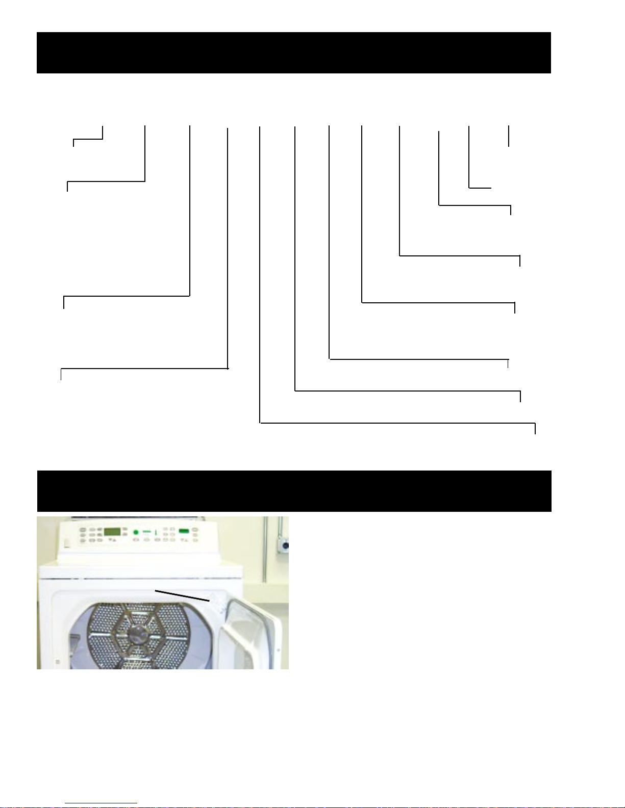
D P S B 6 5 0 E C 0 W W
GE Dryer
Feature Pack
Common Brand Features
Exceptions:
H = Energy Star
P = Profile™
K, N = Special
S = Spacemaker®
Capacity/Configuration
L = Large S = Super
X = Extra-Large K = Compact
Control Platform
B = Buttons (T ouch Pad)
Q = QuickClean S = Stationary
R = Rotary F = Fabric Care
P = Portable H = Horizontal A xi s D ry in g Machine
Backsplash
Color
Body Color
Model Y ear
Designator
Engineering
Revision
Fuel/Voltage
E = Electric
G = Gas
Dryer Control
Number of Cycles
Heat Selections
Model and
Serial Numbers
Note: Model number and serial number are
located on the front panel inside the door .
• The technical sheet is located behind
the control panel.
Serial Number
The first two characters of the serial number
identify the month and year of manufacture.
Example: AD123456S = January 2002
A - JAN 2005 - H
D - FEB 2004 - G
F - MAR 2003 - F
G - APR 2002 - D
H - MAY 2001 - A
L - JUN 2000 - Z
M - JUL 1999 - V
R - AUG 1998 - T
S - SEP 1997 - S
T - OCT 1996 - R
V - NOV 1995 - M
Z - DEC 1994 - L
– 2 –
The letter designating
the year repeats every
12 years.
Example:
T - 1974
T - 1986
T - 1998
Page 5
Warranty
■ Ser vice trips to your home to teach you how to use
the product.
■ Improper installation.
■ Failure of the product if it is abused, misused or used for
other than the intended purpose or used commercially.
■ Replacement of house fuses or resetting of circuit
breakers.
■ Damage to the product caused by accident, fire, floods
or acts of God.
■ Incidental or consequential damage caused by possible
defects with this appliance.
What Is Not Covered:
This warranty is extended to the original purchaser and any succeeding owner for products purchased for home
use within the USA. In Alaska, the warranty excludes the cost of shipping or service calls to your home.
Some states do not allow the exclusion or limitation of incidental or consequential damages. This warranty gives
you specific legal rights, and you may also have other rights which vary from state to state. To know what your
legal rights are, consult your local or state consumer affairs office or your state’s Attorney General.
Warrantor: General Electric Company. Louisville, KY 40225
All warranty service provided by our Factory Service Centers,
or an authorized Customer Care
®
technician. To schedule service,
on-line, 24 hours a day, visit us at www.GEAppliances.com,
or call 800.GE.CARES (800.432.2737).
For The Period Of: We Will Replace:
One Year Any part of the dryer which fails due to a defect in materials or workmanship. During this
From the date of the full one-year warranty, GE will also provide, free of charge, all labor and related service costs
original purchase to replace the defective part.
Second Year Any part of the dryer which fails due to a defect in materials or workmanship. During this
From the date of the additional one-year limited warranty, you will be responsible for any labor or related service costs.
original purchase
Third through Fifth Year The extra large or super capacity dryer drum and main electronic control board if any of these
From the date of the parts should fail due to a defect in materials or workmanship. During this additional three-year
original purchase limited warranty, you will be responsible for any labor or related service costs.
GE Dryer Warranty.
(For customers in the United States)
– 3 –
Page 6
Control Features
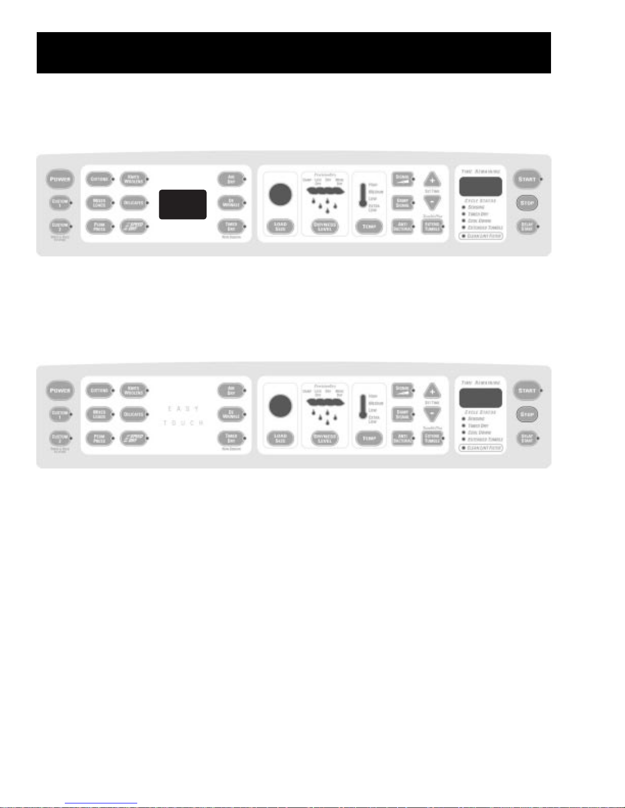
Note: Throughout this manual, features and appearance may vary from your model.
Model DPSB650
Model DPSB620
– 4 –
Page 7
Control Features
START
■ After you have selected a new cycle, press once to start the cycle.
■ Press twice to select the last cycle used and start the dryer.
■ If the dryer is running, press once to interrupt the cycle; press again to continue
the cycle.
STOP
If the dryer is running, press once to interrupt the cycle; press again to cancel the cycle.
Time Remaining
Displays the approximate time remaining until the end of the cycle.
As the cycle begins, you will see the approximate total cycle time in the display. Then
lights will “race” in the display. This means the dryer is continuously monitoring the
amount of moisture in the load. The lights will continue until the dryer senses a low level
of moisture in the load. At that point, the dryer will calculate and display the approximate
time remaining.
– 5 –
Page 8
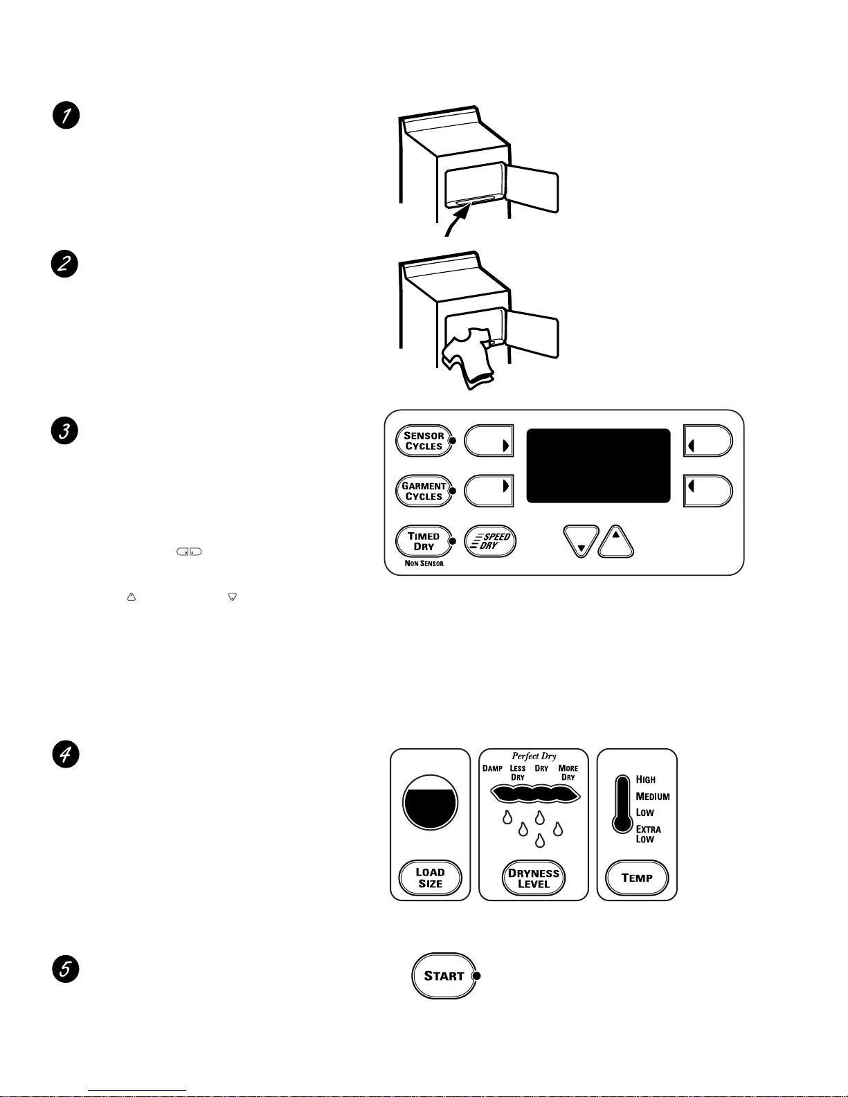
Control Quick Start Cycles (Model DPSB650)
Clean the lint filter.
IMPORTANT: Clean the lint filter each
time you use the dryer.
Add clothes. Do not overload. This wastes
energy and causes wrinkling.
Select one of the three drying methods:
■
Press SENSOR CYCLES to dry according
to load type
■
Press GARMENT CYCLES to dry
according to clothing type
■
Press TIMED DRY to specify dry time
Select the dry cycle by pressing the
arrow pads ( ) at the sides of the
display. You can scroll up and down
through the list of cycles by pressing the
UP ( ) and DOWN ( ) arrow pads
beneath the display.
For TIMED DRY, you can use either the
display or the SET TIME arrow pads to set
the drying time.
NOTE: Any time you make a selection that
is incompatible with the chosen dry cycle,
the dryer will beep twice.
Change any of the automatic settings,
if desired, by pressing the pad beneath
the setting.
■
For best performance, adjust load size
to appropriate setting
■
Dryness level determines how dry your
clothes will be at the end of the cycle
■
Adjust temperature as recommended
on the fabric manufacturer’s care label
Close the door and press START.
– 6 –
Page 9

Control Quick Start Cycles (Model DPSB620)
Clean the lint filter.
IMPORTANT: Clean the lint filter each
time you use the dryer.
Add clothes. Do not overload. This wastes
energy and causes wrinkling.
Select the dry cycle and other
options.
For TIMED DRY, use the SET TIME
arrow pads to set the drying time.
NOTE: Any time you make a selection
that is incompatible with the chosen
dry cycle, the dryer will beep twice.
Change any of the automatic settings,
if desired, by pressing the pad beneath
the setting.
■
For best performance, adjust load size
to appropriate setting
■
Dryness level determines how dry your
clothes will be at the end of the cycle
■
Adjust temperature as recommended
on the fabric manufacturer’s care label
Close the door and press START.
– 7 –
Page 10
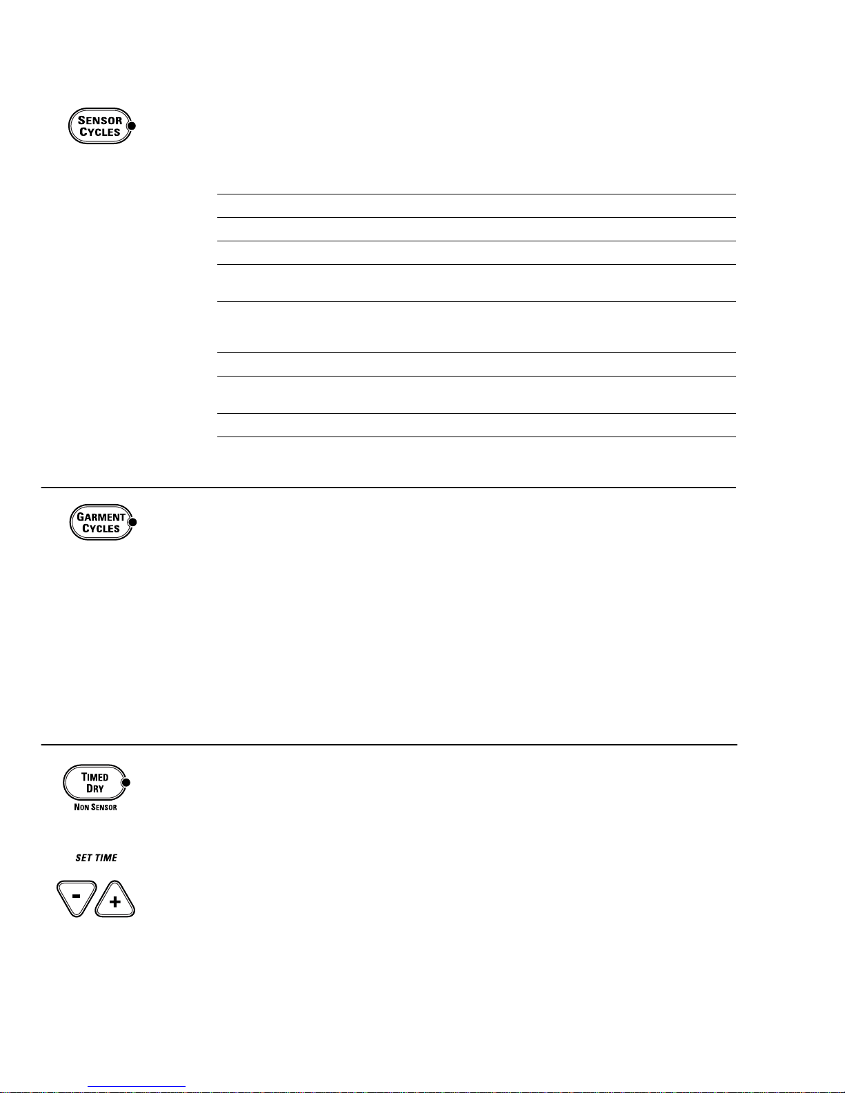
Control Easy T ouch Selections (Model DPSB650)
SENSOR CYCLES
COTTONS For cottons and most linens.
PERM PRESS
For wrinkle-free, permanent press and delicate items, and knits.
MIXED LOAD For loads consisting of cottons and poly-blends.
KNITS For knits with fabric care labels that say “Machine Dry.”
SPEED DRY For small loads that are needed in a hurry, such as sport or school uniforms. Can also
be used if the previous cycle left some items damp, such as collars or waistbands.
DRYEL Designed for use with the DRYEL
™
“dry-clean only” fabric care system. See product
package for directions. For questions or issues related to the use and performance
of DRYEL™, call 1.800.214.8913, or visit the DRYEL™Website at www.dryel.com.
DELICATES For lingerie and special-care fabrics.
DEWRINKLE For removing wrinkles from items that are dry or slightly damp. This cycle is not
recommended for delicate fabrics.
WARM UP Provides 10 minutes of warming time to warm up clothes.
RACK DRY For use with the drying rack.
The Sensor Cycles continuously monitor the amount of moisture in the load and stop
the dryer when the clothes are dry.
GARMENT CYCLES
The Garment Cycles are customized to provide optimum drying for a variety of fabrics
and clothing types.
Garment Cycles include:
■
Jeans
■
Underwear
■
Sheets
■
Dress Shirts
■
Play Clothes
■
Linens
■
Khakis
■
Everyday Wear
■
Infant Wear
■
Knit Shirts
■
Towels
■
Lingerie
■
Athletic Wear
■
Mats/Rugs
■
Washable Silks
Use to set your own drying time. TIMED DRY is also recommended for small loads.
To use TIMED DRY:
1. Press TIMED DRY.
2. Select the drying time.
3. Select the TEMP setting.
4. Select any OPTIONS. (NOTE: The ANTI-BACTERIAL and EXTEND TUMBLE options are
not available with TIMED DRY cycles.)
5. Close door.
6. Push START.
TIMED DRY
– 8 –
Page 11
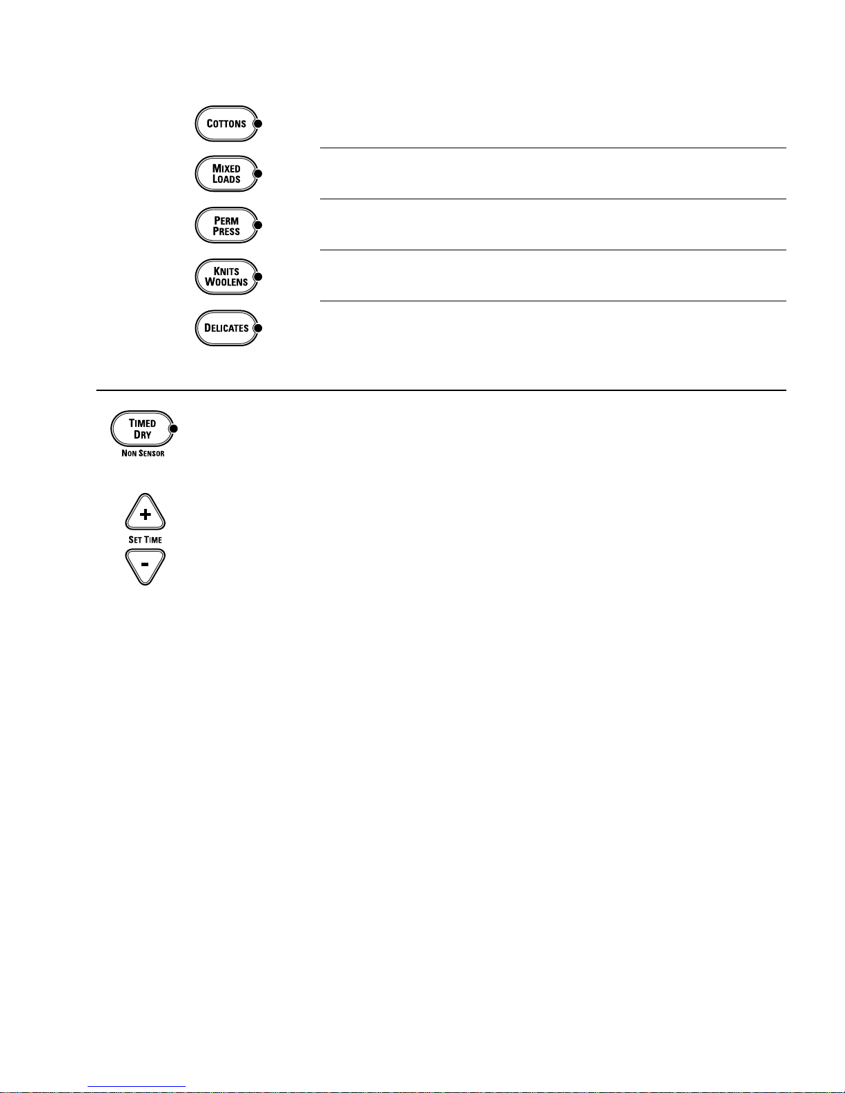
Control Easy T ouch Selections (Model DPSB620)
COTTONS For cottons and most linens.
MIXED LOADS
For loads consisting of cottons and poly-blends.
PERM
PRESS
For wrinkle-free, permanent press and delicate items, and knits.
KNITS For knits with fabric care labels that say “Machine Dry.”
WOOLENS
DELICATES For lingerie and special-care fabrics.
Use to set your own drying time. TIMED DRY is also recommended for small loads.
To use TIMED DRY:
1. Press TIMED DRY.
2. Select the drying time.
3. Select the TEMP setting.
4. Select any options. (NOTE: The ANTI-BACTERIAL and EXTEND TUMBLE options are not
available with TIMED DRY cycles.)
5. Close door.
6. Push START.
TIMED DRY
– 9 –
Page 12
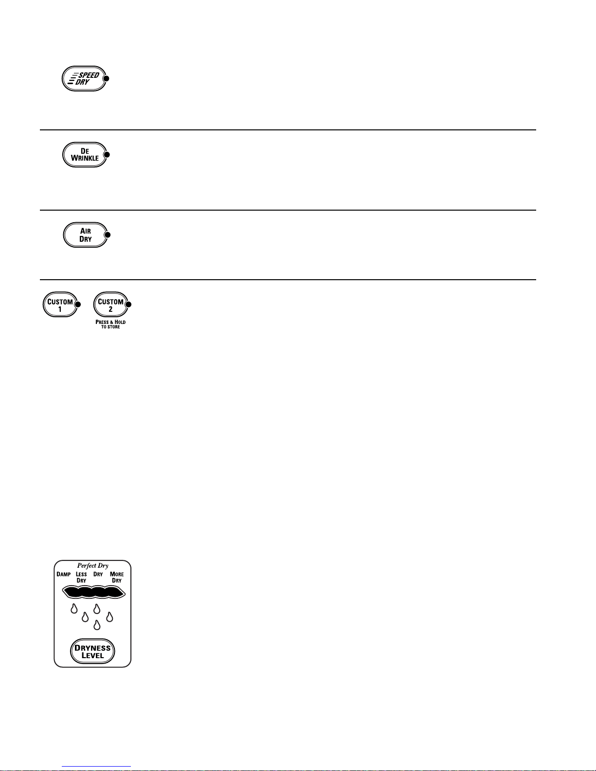
Control Drying Cycles
SPEED DRY
For small loads that are needed in a hurry, such as sport or school uniforms. Can also be
used if the previous cycle left some items damp, such as collars or waistbands.
DEWRINKLE
Use this feature to remove wrinkles from items that are dry or slightly damp. This cycle is
not recommended for delicate fabrics.
AIR DRY
Use this feature to tumble items without heat.
CUSTOM Cycles
(on some models)
Set up your favorite combination of settings and save them here for one-touch recall.
These custom settings can be set while a cycle is in progress.
To store a custom combination of settings:
1. Select an EASY TOUCH setting.
2. Change LOAD SIZE, DRYNESS LEVEL and TEMP setting to fit your needs.
3. Select any drying OPTIONS you want.
4. Press and hold the CUSTOM pad for three seconds to store your selection.
A beep will sound and the pad will light up.
To recall your stored combination:
Press the CUSTOM pad, then press START.
To reprogram the CUSTOM settings:
Repeat steps 1-4 above.
MORE DRY
Use for heavy-duty fabrics.
DRY
Use for a normal dryness level suitable for most loads. This is the preferred cycle
for energy saving.
LESS DRY
Use for lighter fabrics.
DAMP
For leaving items partially damp.
Control Dryness Levels
– 10 –
Page 13

Control Heat Settings
HIGH
For regular to heavy cottons.
MEDIUM
For synthetics, blends and items labeled permanent press.
LOW
For delicates, synthetics and items labeled Tumble Dry Low.
EXTRA LOW
For lingerie and special-care fabrics.
(Appearance and
features may vary)
SIGNAL
Alerts you that the cycle is complete. The beeper will continue to sound every two
minutes for the next 6 minutes, until the clothes are removed. The clothes should
be removed when the beeper goes off so wrinkles won’t set in.
Press SIGNAL to select low, medium or high volume, or to turn the beeper off.
EXTEND TUMBLE PLUS
Minimizes wrinkles by adding approximately 60 minutes of no-heat tumbling after clothes
are dry. The beeper will sound every 5 minutes to remind you to remove the clothes.
The TIME REMAINING display will show 00.
ANTI-BACTERIAL
(on some models)
This option can only be used with the COTTONS or MIXED LOADS cycles. This option
reduces certain types of bacteria by 99.9%, including: Staphylococcus aureus, Pseudomonas
aeruginosa and Klebsiella pneumoniae*. The anti-bacterial process occurs when high heat
is used during a portion of the drying cycle.
NOTE: Do not use this cycle on delicate fabrics.
* The Anti-Bacterial Cycle is Certified by NSF International (formerly National Sanitation
Foundation) to NSF Protocol P154 Sanitization Performance of Residential Clothes Dryers.
NSF Protocol P154
Sanitization Performance of
Residential Clothes Dryers
R
E
S
I
D
E
N
T
I
A
L
Cycle Options
– 11 –
Page 14

DELAY START
(on some models)
Use to delay the start of your dryer.
1. Choose your dry cycle and any options.
2. Press DELAY START. You can change the delay time in 30 minute increments using the
SET TIME arrow pads.
3. Press the START pad to start the countdown.
The countdown time will be shown in the TIME REMAINING display.
NOTE: If the door is opened while the dryer is in DELAY, the countdown time will not
restart unless the door is closed and START has been pressed again.
DAMP SIGNAL
(on some models)
This option causes the dryer to beep when clothes have dried to a damp level. Remove
items that you wish to hang dry. The DAMP SIGNAL will only beep when the dryer SIGNAL
is turned on.
Removing clothes and hanging them when they are damp can reduce the need to iron
some items.
The cycle status indicator lights (on some models) show what part of the cycle the dryer is in and remind you to
clean the lint filter. On models without indicator lights, the cycle status will show in the display.
SENSING
This light comes on when an E
ASY
T
OUCH
Sensor Dry Cycle is active.
TIMED DRY
This light comes on when AIR DRY, DEWRINKLE, DRYEL™(on some models), TIMED DRY
or RACK DRY is selected.
EXTENDED TUMBLE
This light comes on when the dryer is in the EXTEND TUMBLE mode.
CLEAN LINT FILTER
This light is a reminder to clean the lint filter. It comes on at the end of a cycle and
goes off when the door is opened.
Cycle Status
– 12 –
Page 15
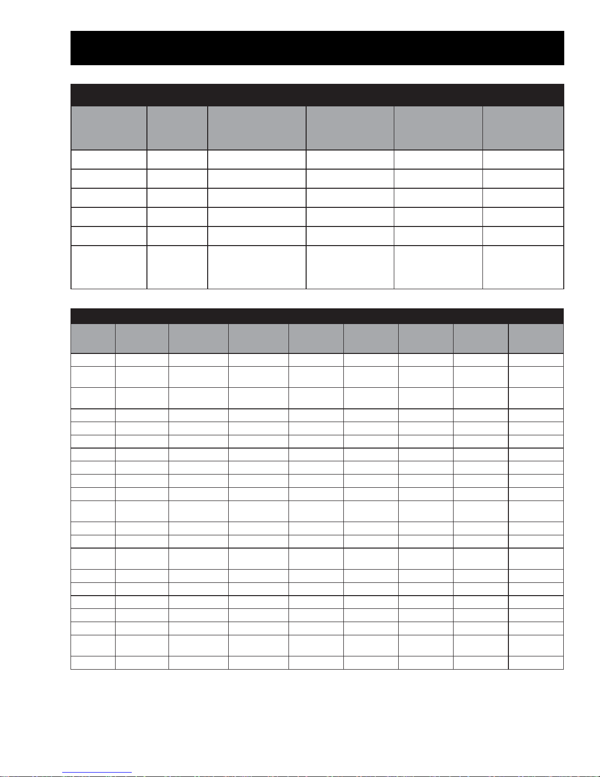
Cycle Chart
selcyCemiT
elcyC
Air Dry
De-Wrinkle
Dryel
Warm-Up
Rack Dry
tluafeD
gniyrD
emiT
10
10
20
10
30
0
5
5
0
10
dexiF
nwodlooC
emiT
None
Medium
Medium
Medium
Medium
gniyrDtluafeD
erutarepmeT
gniyrDlanoitpO
erutarepmeT
None
Medium
Medium
Any
Any
Generic
(10 minutes
30
5
Medium
Any
to 120 min)
selcyCrosneS
rosneS
elcyC
snottoCmuideMynAyrDynAhgiHynA5 F°411
sdaoLdexiMmuideMynAyrDynAhgiH
tnenamreP
sserP
stinKllamSynAyrDsseLynAwoLwoLartxE5F°79
yrDdeepSllamSynAyrDynAhgiHhgiH2 F°411
setacileDllamSynAyrDsseLynAwoLartxEwoL5 F°79
snaeJmuideMynAyrDeroMynAhgiHynAelbairaVF°411
sikahKmuideMynAyrDynAhgiHynAelbairaVF°411
strihSsserDllamSynAyrDynAmuideMynAelbairaVF°79
strihStinKmuideMynAyrDynAmuideMynAelbairaVF°411
citelhtA
raeW
sehtolCyalPmuideMynAyrDeroMynAhgiHynAelbairaVF°411
raewrednUllamSynAyrDynAmuideMynAelbairaVF°411
yadyrevE
raeW
slewoTmuideMynAyrDeroMynAhgiHynAelbairaVF°411
steehSmuideMynAyrDeroMynAhgiHynAelbairaVF°411
sguR/staMmuideMynAyrDynAmuideMynAelbairaVF°411
neniLelbaTllamSynAyrDynAmuideMynAelbairaVF°79
raeWtnafnImuideMynAyrDynAmuideMynAelbairaVF°411
elbahsaW
skliS
eiregniLllamSynAyrDsseLynAwoLartxEwoLartxEelbairaVF°79
daoLtluafeD
eziS
muideMynAyrDynAmuideMynA01F°79
llamSynAyrDsseLynAmuideMynAelbairaVF°411
muideMynAyrDynAmuideMynAelbairaVF°411
llamSynAyrDynAwoLartxEwoLelbairaVF°79
daoLlanoitpO
seziS
ssenyrDtluafeD
leveL
lanoitpO
leveLssenyrD
gniyrDtluafeD
erutarepmeT
lanoitpO
gniyrD
erutarepmeT
,woL,woLxE
muideM
mumixaM
emiT
5F°411
elbatsujdA
emiTgniyrD
Yes
Yes
No
Yes
Yes
Yes
nwoD-looC
nwoD-looC
erutarepmeT
F°411
Note:
• The DSSD will display cd during the cooldown portion of the cycle.
• During sensor drying, if the sensor rods are not shorted within the first 6 minutes of the cycle, the
unit will determine that the drum is empty and terminate the drying cycle.
– 13 –
Page 16
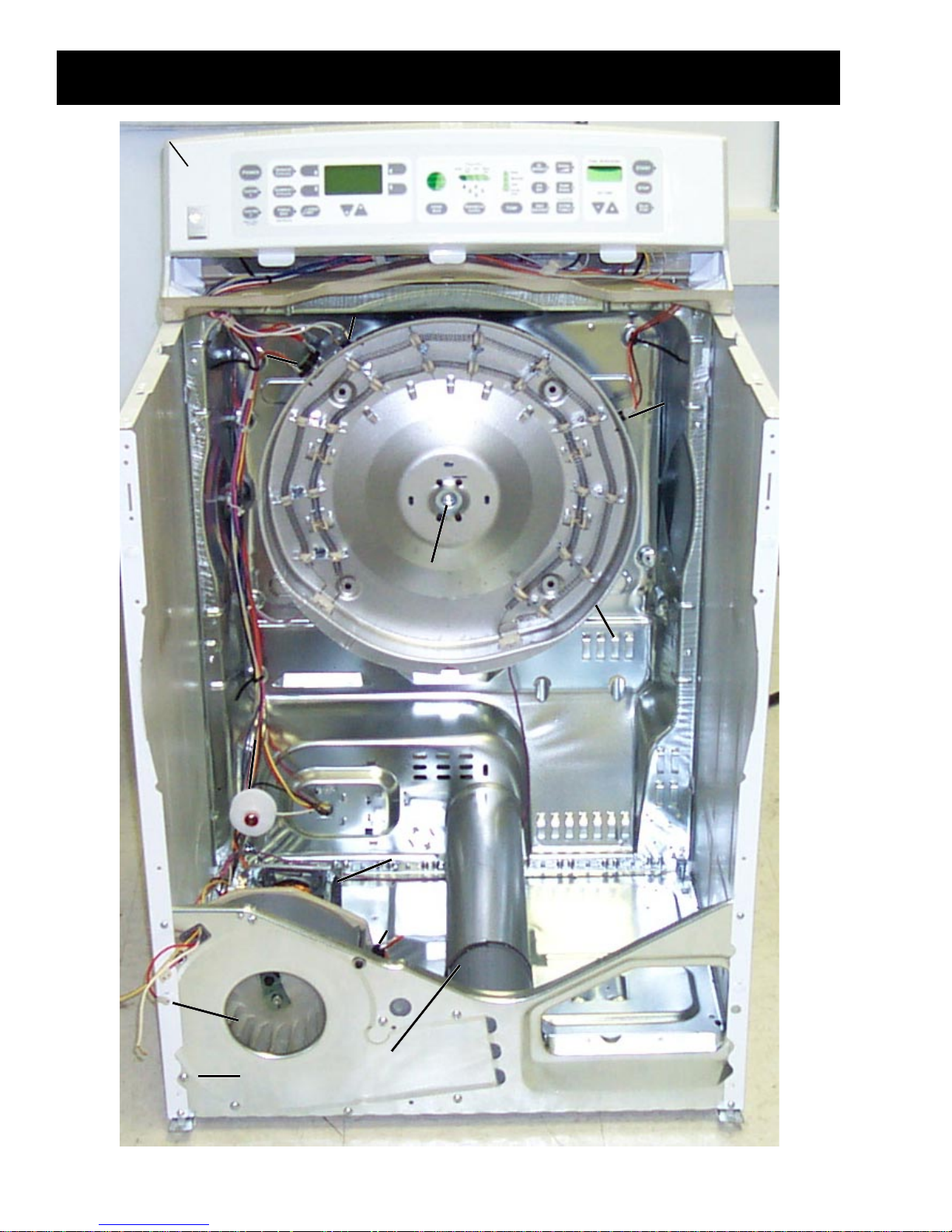
Control Panel
Control Panel
Inlet Safety
Inlet Safety
Thermostat
Thermostat
Component Locator View
Inlet Thermistor
Inlet Thermistor
Hi-Limit
Hi-Limit
Thermostat
Thermostat
Blower
Blower
Wheel
Wheel
Idler Pulley
Idler Pulley
Bearing Retainer
Bearing Retainer
Motor
Motor
Outlet Control
Outlet Control
Thermostat
Thermostat
Outlet Thermistor
Outlet Thermistor
(in blower housing)
(in blower housing)
Heater Assembly
Heater Assembly
Belt Switch
Belt Switch
(on motor bracket)
(on motor bracket)
Electric Model
– 14 –
Page 17
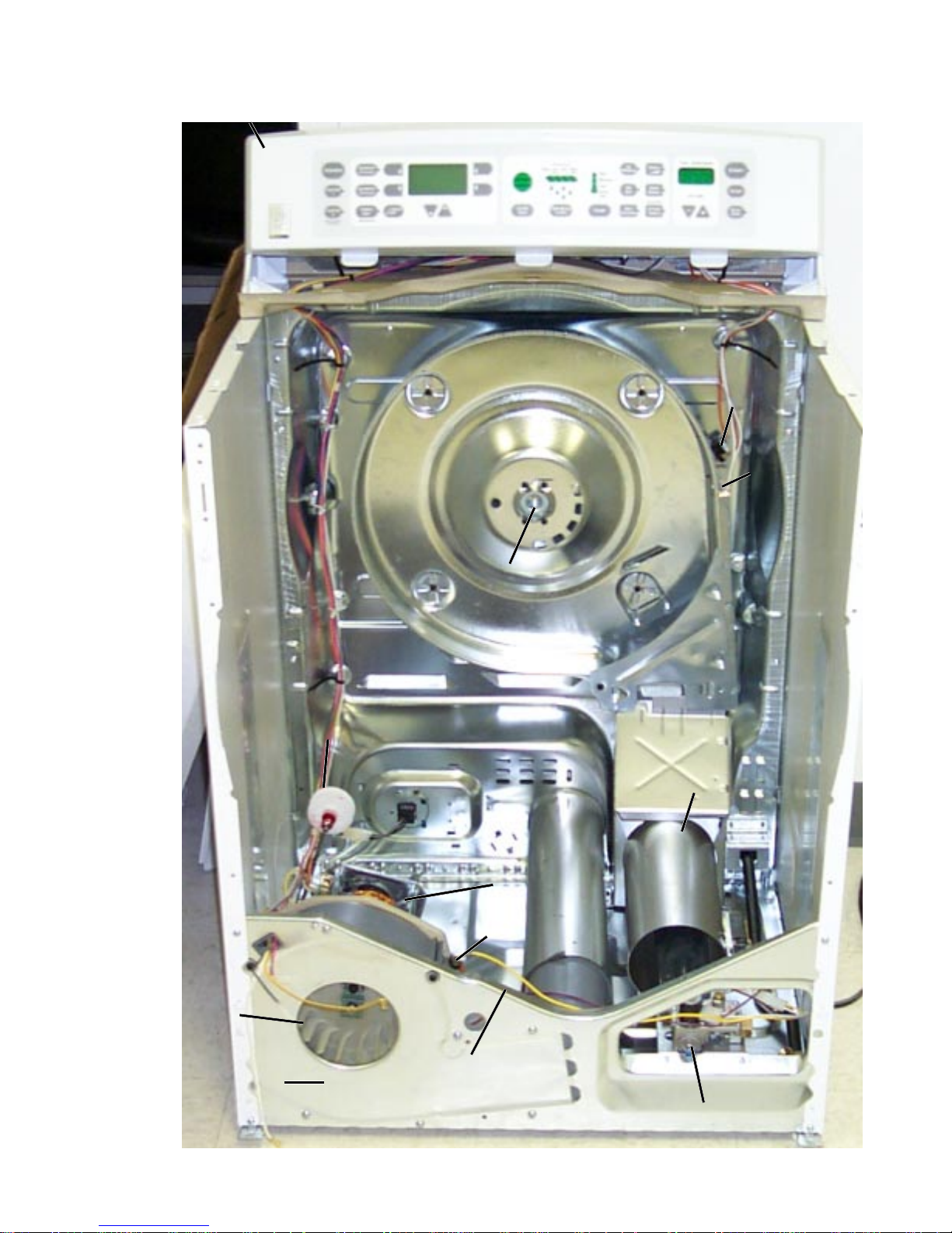
Control Panel
Control Panel
Inlet Safety
Inlet Safety
Thermostat
Thermostat
Inlet Thermistor
Inlet Thermistor
Blower
Blower
Wheel
Wheel
Idler Pulley
Idler Pulley
Bearing Retainer
Bearing Retainer
Motor
Motor
Outlet Control
Outlet Control
Thermostat
Thermostat
Outlet Thermistor
Outlet Thermistor
(in blower housing)
(in blower housing)
Combustion
Combustion
Chamber
Chamber
Belt Switch
Belt Switch
(on motor bracket)
(on motor bracket)
Gas Model
– 15 –
Gas V a l v e
Gas V a l v e
Page 18
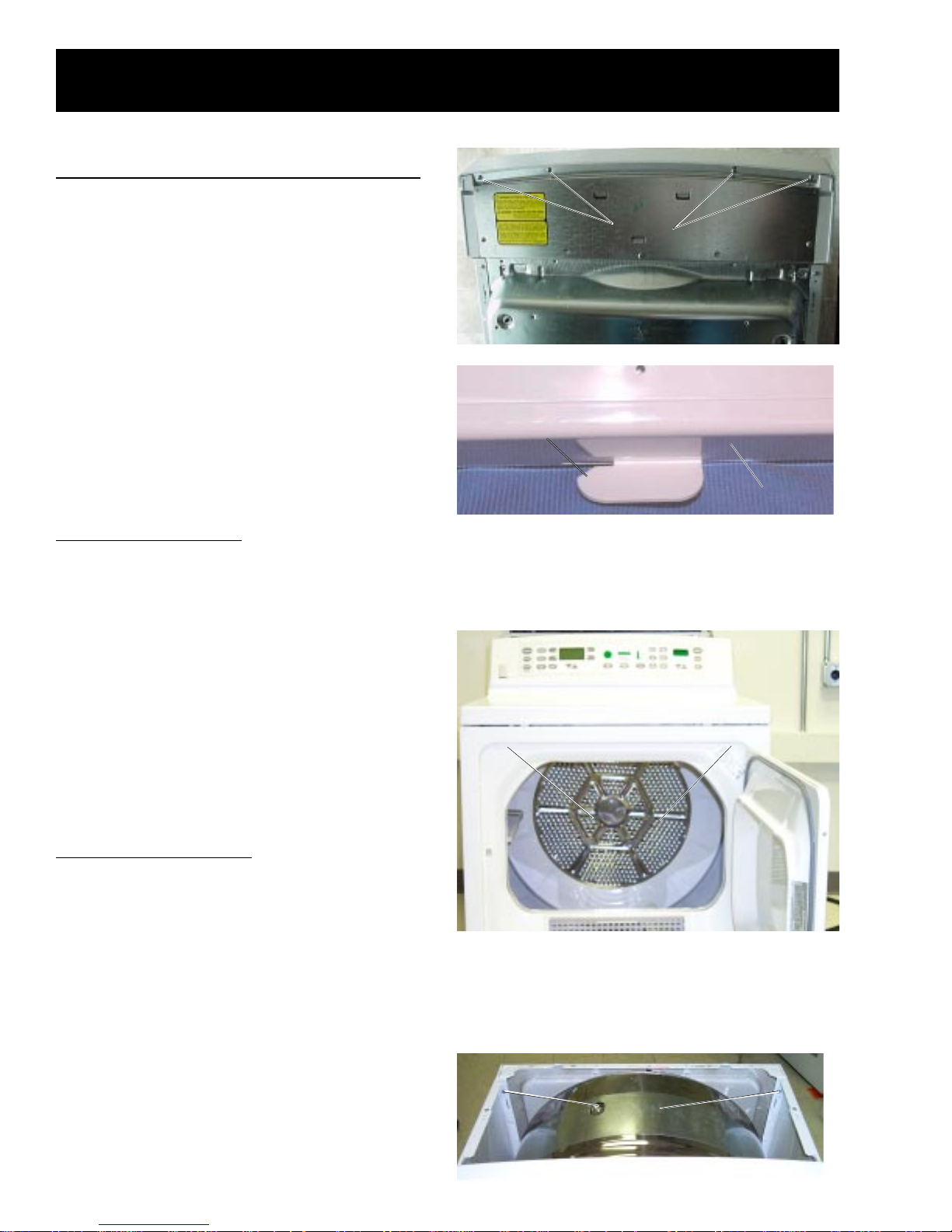
Dryer Components
Control Panel
To place the control panel in the service position:
1. Remove 4 screws from the rear of the control
panel.
2. Gently pull on each corner to unsnap the
control panel from the sides of the unit.
3. Rotate the control panel forward approximately
1 inch and slide to the right to unlock the
bottom locking tabs.
4. Lift up and off the top panel.
Screws
Screws
T op Panel
The top panel is fastened at the front by 2 screws
and at the rear by locking tabs protruding from the
bottom of the control panel.
To remove the top panel:
1. Remove the control panel.
2. Remove 2 screws that secure the top panel to
the cabinet and the top panel.
Front Panel
Warning: Sharp edges may be exposed when the
front panel is removed. Use caution to avoid injury
when servicing dryer .
The front panel is fastened to the cabinet at the
inside front by 2 screws and at the bottom by 2
tabs protruding from the base of the cabinet.
To remove the front panel:
Locking Tab
Locking T ab
Screws
Screws
Control
Control
Panel
Panel
1. Remove the control panel and top panel. (See
Control Panel and Top Panel.)
2. Remove 2 screws from the front inside edge of
the front panel.
3. T ilt the top edge of the front panel out and lift off
the bottom tabs.
4. Disconnect wiring to the door switch, light, and
sensor rods and remove the front panel.
– 16 –
Screws
Screws
Page 19
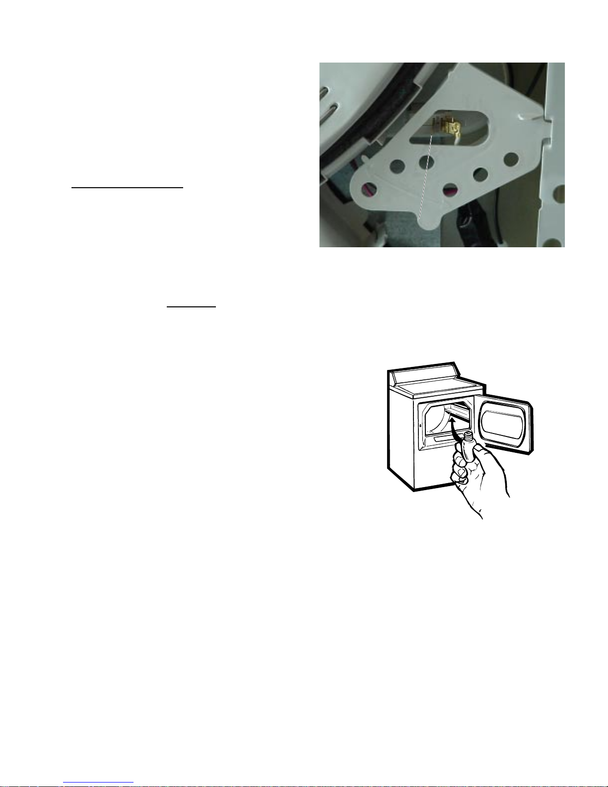
Door Switch
The door switch is fastened to the front panel by
2 locking tabs and is common to all dryer
functions. When the dryer door is closed, the
switch will complete the motor circuit, allowing
dryer operation. When the dryer door is open,
the switch will open the motor circuit, interrupting
dryer operation. Opening the dryer door will also
cause the door switch to close the drum light
circuit, allowing the drum light to be energized.
To test the door switch:
Place the unit in service mode. Index to the door
switch function. Open and close the door while
observing the DSSD. When the door is open,
OPn should be displayed on the DSSD. When
the door is closed, CLS should be viewed on the
DSSD.
Note: If the dryer door switch has not opened
after 3 consecutive
will log the door switch error code and disable
the dryer . See Error Codes.
completed cycles, the dryer
Door Switch
Door Switch
Drum Light
The drum light is a screw-in 10-watt, 120-V AC
bulb located in the top of the front panel. The
light is connected to the L2 circuit for electric
models and to L1 for gas models. Both models
are switched on the neutral side by the door
switch. Replace only with a bulb of the same
size and type.
Drum
Warning: Sharp edges may be exposed. Use extreme caution when removing the drum.
The dryer drum is made of stainless steel and has 3 replaceable drum vanes attached to the inside.
The drum is mounted in the same manner as the previous Wizard model. The rear of the drum has a
shaft and bearing that fits into a bearing retainer , which is fastened to the center of the heater assembly .
The front of the drum rides on a slide assembly consisting of 2 guide slides and 2 weight-bearing slides.
– 17 –
Page 20
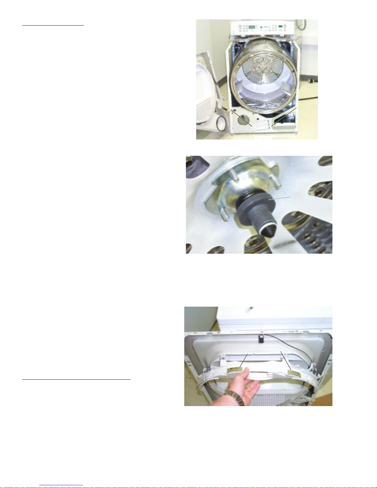
To remove the drum:
1. Remove the top panel and the front panel. (See
T op Panel and Front Panel.)
2. Remove the drive belt from the motor . (See
Belt.)
3. Remove 1 screw from each side of the cabinet
and gently spread the sides apart to provide
clearance for the tub.
4. Using the belt as a handle, pull the drum
forward and guide out of the cabinet.
Drum Shaft Bearing
The drum shaft bearing (PN WE25M40) is mounted
on the drum shaft at the rear of the drum. The
bearing fits into the bearing retainer in the center of
the heater assembly .
Caution: Do not lubricate the drum shaft or
bearing.
Screws
Screws
Drum Shaft
Drum Shaft
Bearing
Bearing
Drum Slide Assembly
The drum slide assembly , located on the back side
of the front panel, utilizes 4 drum slides. T wo white
outer slides are used as guides, and 2 dark color
center (top) slides are used to support the weight of
the drum. When replacing the slides, the dark color
support slides must be replaced with the support
slide replacements. Guide slides may also be
replaced with support slides. Do not replace the
center (top) support slides with white guide
slides. Damage to the dryer will result.
To remove the drum glide assembly:
1. Remove the top panel and the front panel. (See
T op Panel and Front Panel.)
2. Remove the drum lightbulb.
3. Grasp the top, inside edge of the support
assembly and unsnap the support from the front
panel and remove.
Slide Support
Slide Support
Assembly
Assembly
Guide Slide
Guide Slide
Support Slides
Support Slides
Guide Slide
Guide Slide
– 18 –
Page 21
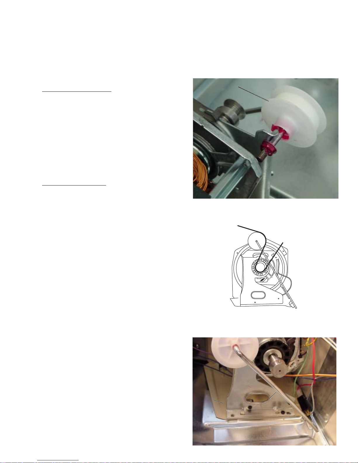
Drive Belt
Warning: Sharp edges may be exposed. Use
caution to avoid injury when removing or installing
the drive belt.
The drive belt (P/N WE12M22) extends from the
motor pulley , past the idle pulley , and around the
perimeter of the dryer drum. (See belt diagram.)
To remove the drive belt:
1. Remove the top panel and front panel. (See
T op Panel, and Front Panel.)
2. Reach under the left-hand side of the drum,
push the idler pulley down and to the right, and
lock the pulley shaft on the top corner of the
motor bracket to release belt tension.
(See photo.)
3. Remove the belt from the motor pulley and
remove through the front of the dryer .
To install the drive belt:
Idler Pulley
Idler Pulley
1. Remove the top and front panels. (See T o p
Panel and Front Panel.)
2. Reach under the left-hand side of the drum,
push the idler pulley down and to the right and
lock the pulley shaft on the top corner of the
motor bracket. (See photo.)
3. Place the belt in position around the center of
the drum through the front of the dryer .
4. Place the belt in position around the motor
pulley (see diagram), release the idler pulley
from the motor bracket, and guide onto the belt.
5. Check to make sure the belt is in place and not
twisted before installing the top and front
panels.
Belt Switch
A belt switch, activated by the idler spring, is
fastened to the motor bracket by 2 screws. Should
the drive belt break, the belt switch will open the
drive motor circuit, interrupting dryer operation.
Pulley shown in locked position.
Motor
Motor
Bracket
Bracket
– 19 –
Idler Spring
Idler Spring
Belt Switch
Belt Switch
Page 22
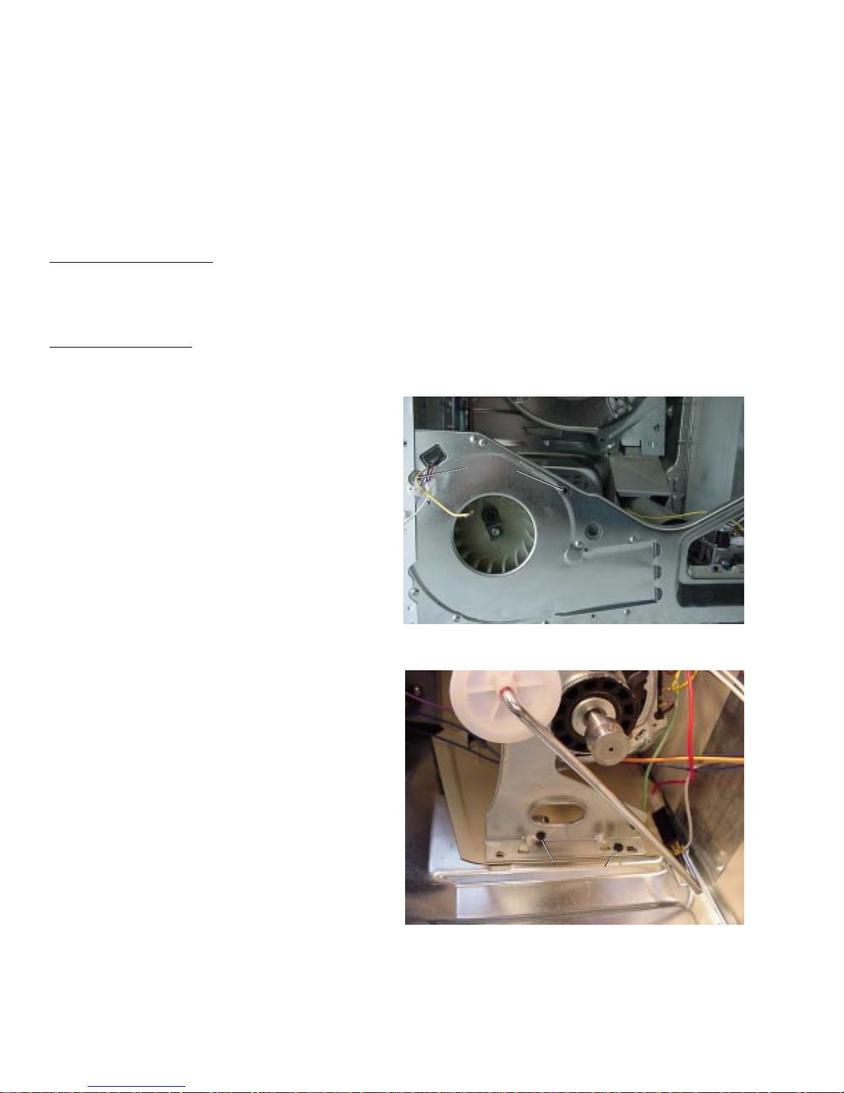
Motor and Blower Wheel
The drive-motor is a single-speed, dual-shaft,
¼-hp, 1725-rpm motor with an automatic reset
overload protector. The overload protector is an
internal component of the motor and cannot be
replaced separately . The motor contains a
centrifugal switch that serves three purposes: It
disengages the motor start winding (M6), engages
the motor run winding (M5), and closes the circuit
contacts (M1 to M2) for the heat source.
Motor resistance values:
Start winding = 5 ohms
Run winding = 4 ohms
To remove the motor:
1. Disconnect power to the unit.
2. Remove the top panel, the front panel, and the
drum. (See Top Panel, Front Panel,
and Drum.)
3. Remove 2 Phillips screws fastening the blower
housing to the cabinet.
4. Remove 1 (Phillips) screw and 1 (1/4-in.)
screw fastening the motor bracket to the
cabinet.
5. Disconnect the motor and belt switch wiring.
Screws
Screws
– 20 –
Screws
Screws
Page 23
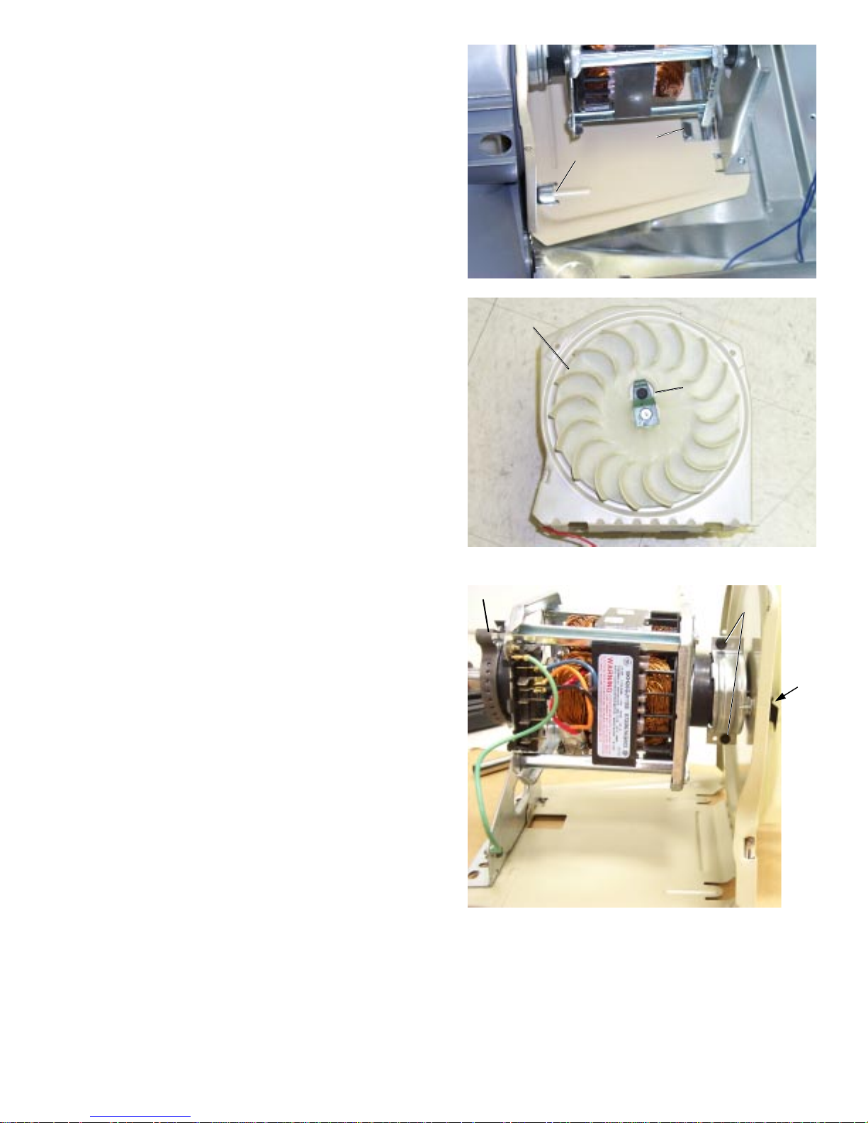
6. Lift the rear of the motor bracket up and over
the tab protruding from the dryer bottom.
7. Slide the motor bracket back until the bracket
tabs clear the slots in the base of the cabinet.
Remove the blower and motor .
8. Disconnect the motor ground wire from the
motor bracket.
Bracket
Bracket
Tab
Tab
Tab
Ta b
9. Loosen the blower wheel clamp and pull the
blower off the motor shaft.
10 . Remove 2 screws (from the blower side of the
motor bracket) securing the front motor strap.
1 1. Loosen 2 motor strap screws and remove the
front motor strap from the motor .
12 . Compress the rear motor strap and remove
from the motor bracket.
Blower Wheel
Blower Wheel
Motor Strap
Motor Strap
Blower Wheel
Blower Wheel
Clamp
Clamp
Strap
Strap
Screws
Screws
ScrewsScrews
13 . Remove the motor from the bracket.
– 21 –
Page 24
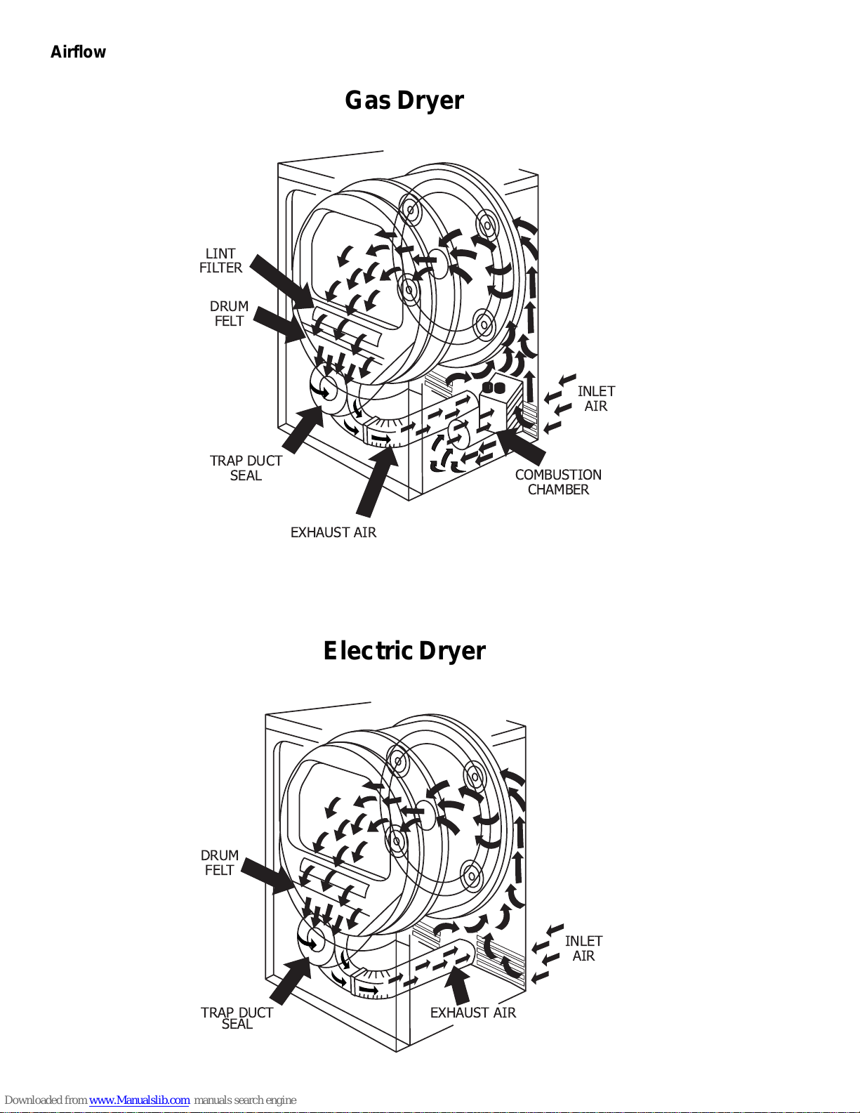
Airflow
LINT
FILTER
DRUM
FELT
TRAP DUCT
SEAL
GAS DRYER
Gas Dryer
INLET
AIR
COMBUSTION
CHAMBER
DRUM
FELT
EXHAUST AIR
ELECTRIC DRYER
Electric Dryer
TRAP DUCT
SEAL
INLET
AIR
EXHAUST AIR
– 22 –
Page 25
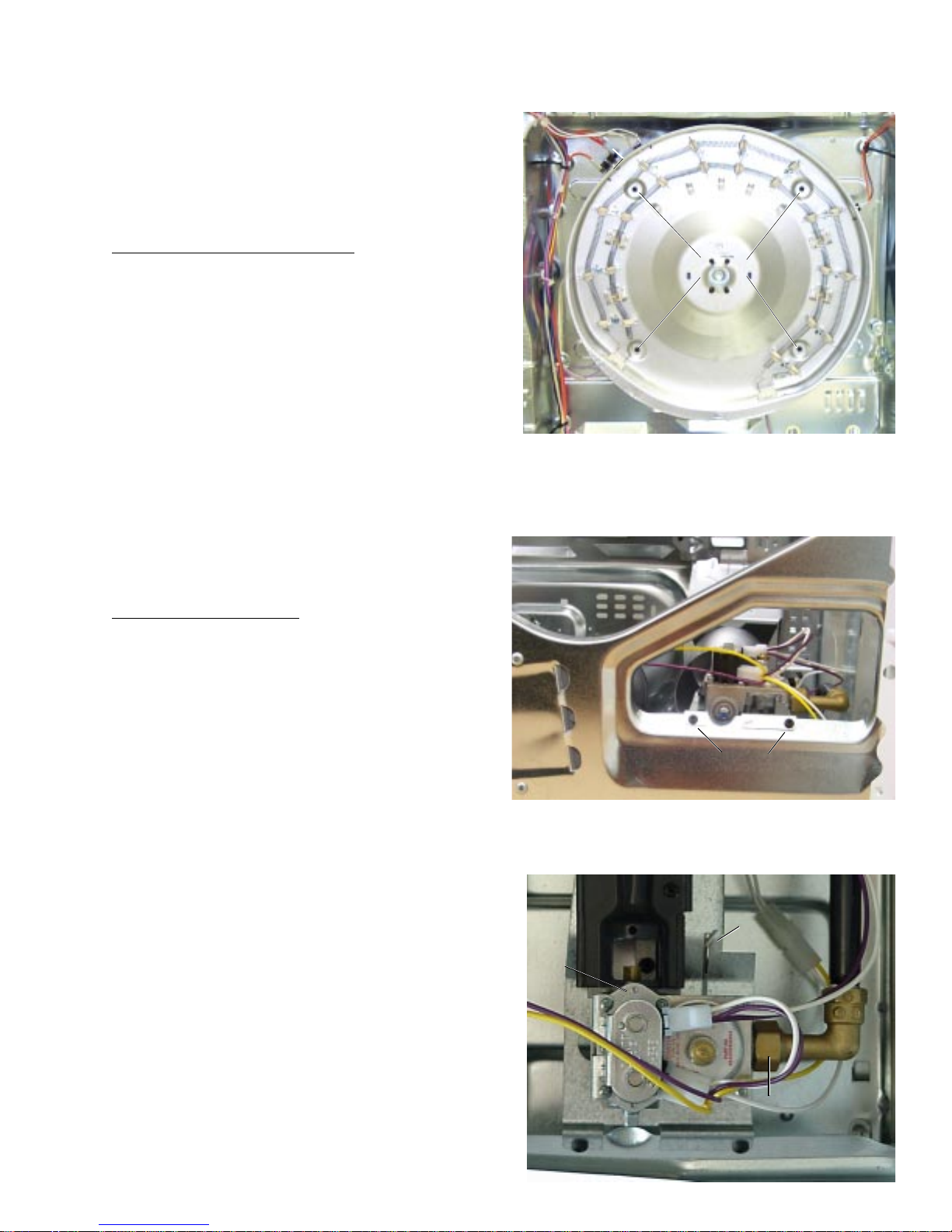
Heater Assembly (electric models)
The heater assembly is located behind the drum
and consists of 2 open coils fastened to a single
housing. Holes in the back of the drum allow air to
be drawn over the heating coils and into the drum.
Each heater coil is individually controlled by a
separate relay on the board and should have a
resistance reading of approximately 20 ohms.
To remove the heater assembly:
1. Remove the top panel, the front panel, and the
drum. (See Top Panel, Front Panel,
and Drum.)
2. Disconnect the lead wires from the heaters,
thermistor, inlet safety thermostat, and hi-limit
thermostat.
3. Remove 4 screws and the heater assembly .
Gas V alve
Heater
Heater
Assembly
Assembly
Screws
Screws
The gas valve is mounted by 2 screws to the front
right-hand side of the cabinet, behind the front
panel.
To remove the gas valve:
1. Shut the gas off to the unit.
2. Remove the top panel, front panel, and drum.
(See T op Panel, Front Panel, and Drum.)
3. Disconnect the elbow coupling from the gas
valve by turning counterclockwise (toward the
rear of the dryer).
Gas
Gas
Valve
Valve
Screws
Screws
Tab
Tab
4. Straighten the tab fastening the gas valve to
the dryer bottom.
5. Disconnect the wiring from the gas valve.
6. Remove 2 screws fastening the gas valve to
the cabinet, lift the valve off the tab, and
remove.
– 23 –
Elbow
Elbow
Page 26
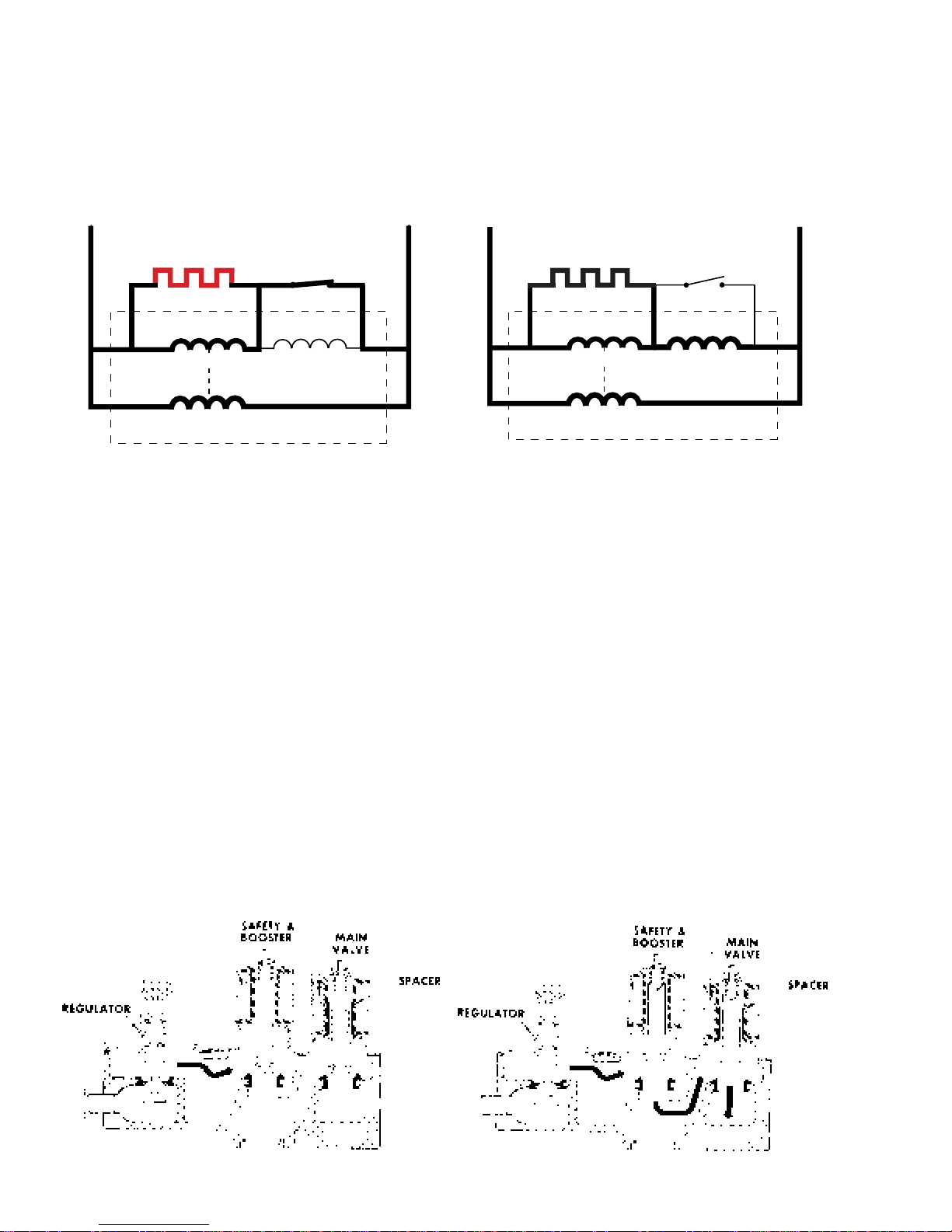
Glo-Bar Igniter Circuit Operation
The glo-bar igniter circuit is made up of the following components: a gas valve with safety and main
valve s, a glo -bar ign iter , and a flame detector . The safety valve is actuated by a double coil, that
comprises a safety coil (resistance approximately 1400 ohms) and a booster coil (resistance
approximately 580 ohms). Both coils are needed to open the safety valve. Once energized, the safety
coil alone will hold the valve open. The main valve has a single coil (resistance approximately
1300 ohms).
L1
N
L1
N
IGNITOR
(GLOWING RED)
BOOSTER
SAFETY
Ignitor On
DETECTOR
MAIN
IGNITOR
(NOT GLOWING)
BOOSTER
SAFETY
Gas Valve Open
DETECTOR
MAIN
The flame detector (< 1 ohm) is mounted on the combustion chamber . It is normally in the closed
position (N.C.). The flame detector is opened by the radiant heat produced by the glo-bar; and once
open, the flame detector will be held open by the radiant heat produced by the gas flame.
When the control system calls for heat, the following circuits are energized:
1. N- through detector, igniter , outlet control backup, inlet safety thermostats to L1.
2. N- through detector, booster coil, outlet control backup, inlet safety thermostats to L1.
3. N- through safety coil and outlet control backup, inlet safety thermostats to L1.
When the glo-bar is heating, the booster and safety coils are both energized and will open the safety
valve. The main valve is closed as its coil is bypassed by the N.C. flame detector . When the glo-bar
reaches ignition temperature, approximately 60 seconds or less, the flame detector is heated and
opens, which places the main coil in series with the glo-bar . The main valve opens, allowing gas to flow
into the combustion chamber and ignite.
The main coil, now in series with the glo-bar , causes the glo-bar to cool down. However , the flame
detector is held open by the radiant heat from the gas flame. The booster coil is now also in series with
the main coil and is essentially inoperative. Should a momentary power failure occur , the gas valve will
shut off and an attempt to restart will not occur until the flame detector cools and resets, approximately
30 seconds.
Valves Closed
– 24 –
Valves Open
Page 27
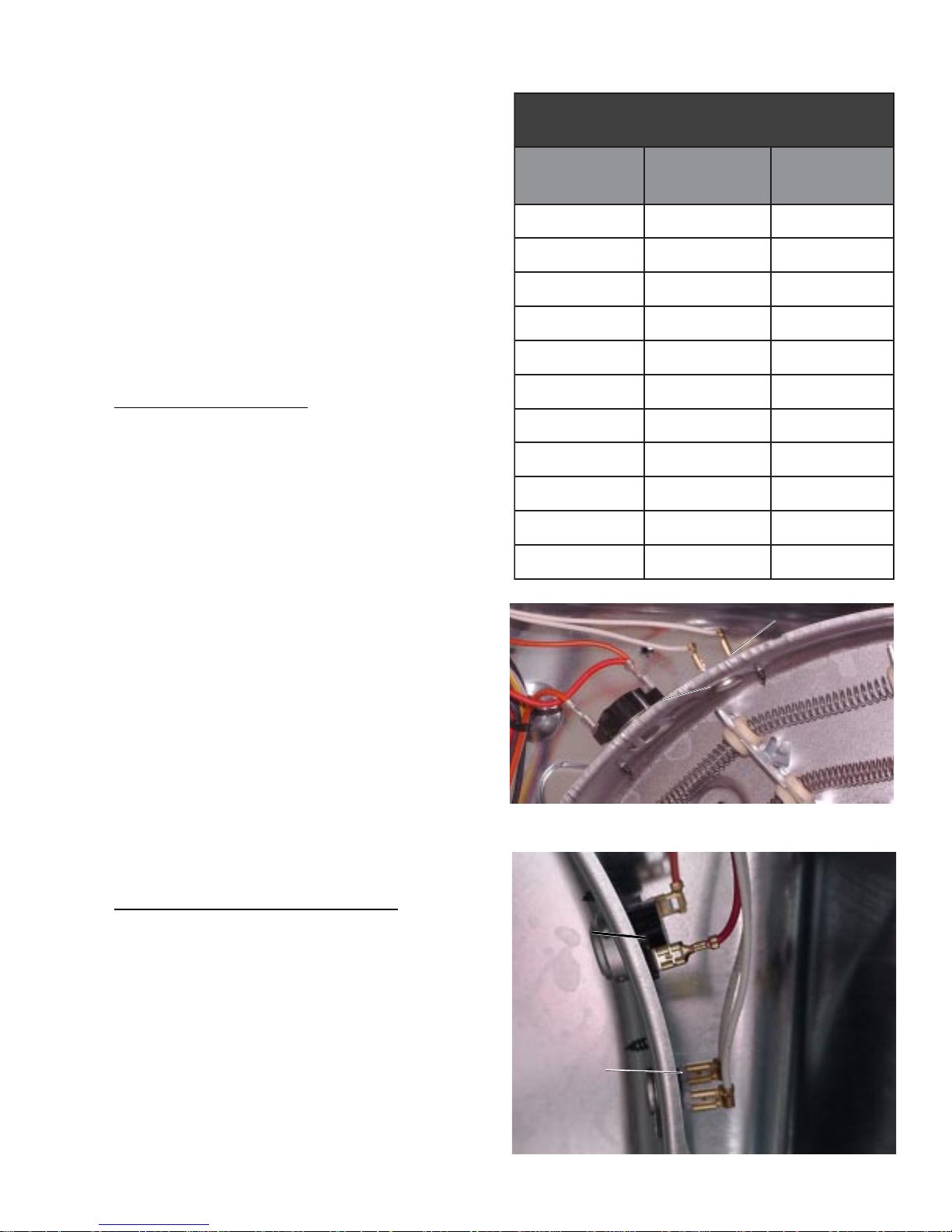
Inlet Thermistor
seulaVecnatseRrotsimrehT
erutarepmeT
C°
erutarepmeT
F°
ecnatsiseR
smho-K
0105202
6106151
1207021
5277001
230947
8300175
9402173
7553172
6605191
390028
1210523
The inlet thermistor is located on the top left side
of the heater housing on electric models and on
the top right side of the housing on gas models.
The inlet thermistor measures the inlet air
temperature and will respond to temperature
changes of 3 °F . The inlet thermistor provides
temperature change information to the electronic
control board. The electronic control board makes
heating decisions based on this information. The
thermistor’s resistance has a negative coef fi cient,
as the temperature increases, the thermistor’s
resistance decreases.
T o check thermistor resistance, refer to the
thermistor resistance chart.
To remove the thermistor:
1. Remove the top panel, the front panel, and the
drum. (See Top Panel, Front Panel and
Drum.)
2. Disconnect the lead wires to the thermistor .
3. Remove 1 screw and the thermistor .
Inlet Safety Thermostat
An inlet safety thermostat is located on the left side
of the heater housing on electric dryer models, and
on the right side of the housing on gas dryer
models. The electric model has an L210-30 °F
rating and the gas model has an L300-40 °F rating.
The inlet thermostat is wired in series with the
outlet control thermostat. If the thermostat
reaches 210 °F on electric models or 300 °F on
gas models, it will open the L1 side of the heater or
gas valve circuit, interrupting heater or gas valve
operation. The thermostat will close when it has
cooled to 180 °F on electric models and 260 °F on
gas models, restoring heater operation.
To remove the inlet safety thermostat:
1. Remove the top panel, the front panel, and the
drum. (See Top Panel, Front Panel
and Drum.)
Inlet
Inlet
Thermistor
Thermistor
Inlet
Inlet
Safety
Safety
Thermostat
Thermostat
Electric Model
Inlet Safety
Inlet Safety
Thermostat
Thermostat
2. Disconnect the thermostat wiring.
3. Remove 1 screw and the thermostat.
– 25 –
Inlet
Inlet
Thermistor
Thermistor
Gas Model
Page 28
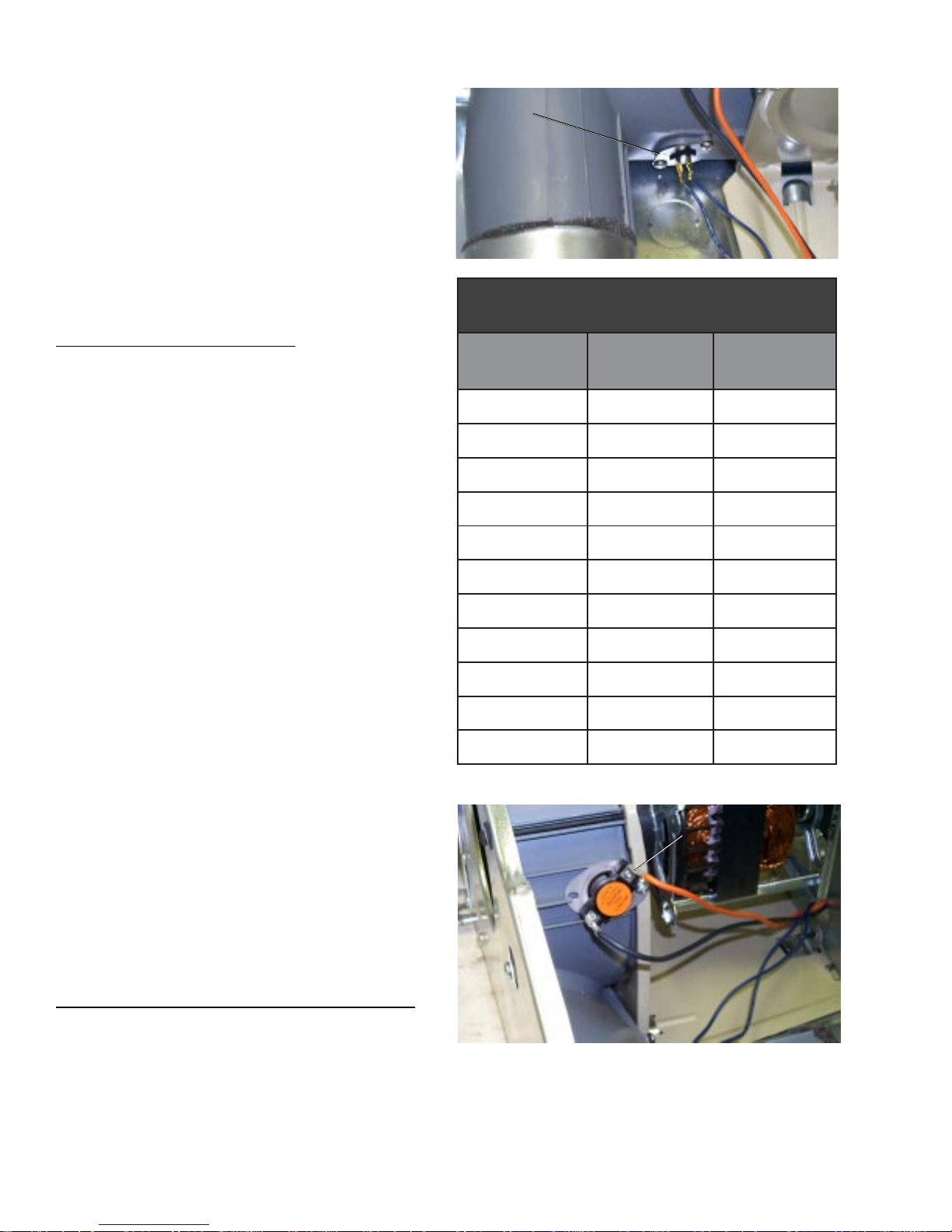
Outlet Thermistor
The outlet thermistor is attached to the blower
housing. The outlet thermistor reads the
temperature of the air being exhausted from the
dryer and will respond to temperature changes of
3 °F . The outlet thermistor provides temperature
change information to the electronic control board.
The electronic control board makes heating
decisions based on this information.
The thermistor’s resistance has a negative
coefficient. As the temperature increases, the
ther mi st or’ s resistance decreases.
To remove the outlet thermistor:
1. Remove the top panel, the front panel, and the
drum. (See Top Panel, Front Panel,
and Drum.)
2. Disconnect the thermistor wiring.
3. Remove 2 screws and the thermistor .
Outlet Thermistor
Outlet Thermistor
erutarepmeT
C°
F°
erutarepmeT
0105202
6106151
1207021
5277001
seulaVecnatseRrotsimrehT
ecnatsiseR
smho-K
Outlet Control Backup Thermostat
An L165-10 °F outlet control backup thermostat is
located on the blower housing. The same
thermostat is used on both gas and electric
models. It is wired in series with the inlet safety
thermostat and heater relay . If the thermostat
reaches 165 °F , it will open the L1 side of the
heater circuit, interrupting heater operation. The
thermostat will close when it has cooled to 155 °F ,
restoring heater operation.
230947
8300175
9402173
7553172
6605191
390028
1210523
Outlet Control
Outlet Control
Backup Thermostat
Backup Thermostat
To remove the outlet control backup thermostat:
1. Remove the top panel and the front panel.
(See T op Panel and Front Panel.)
2. Disconnect the thermostat wiring.
3. Remove 1 screw and the thermostat.
– 26 –
Page 29
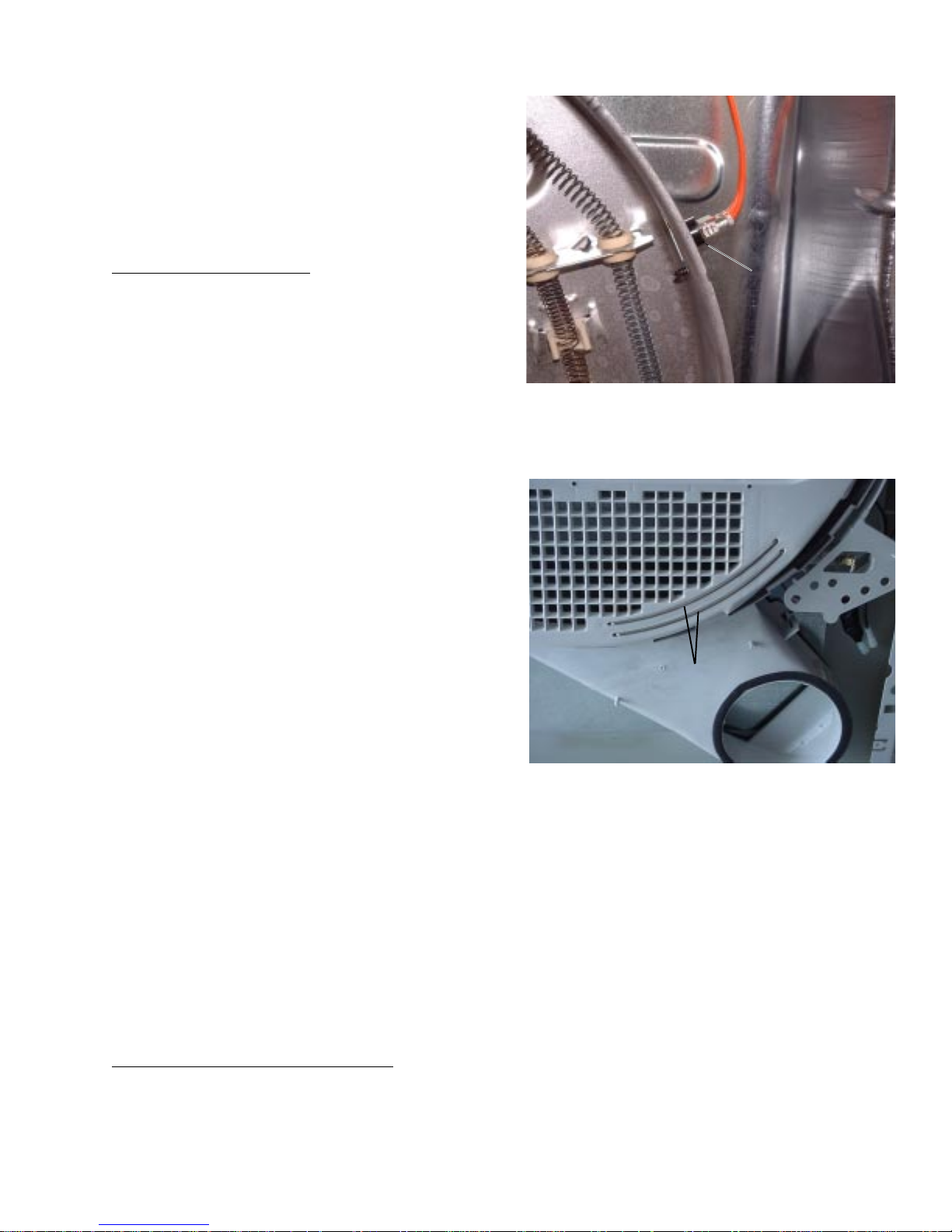
Hi-Limit Thermostat (Electric Models)
An L315-65F hi-limit thermostat is located on the left
side of the heater assembly (electric models only).
The hi-limit thermostat is wired in series with the L1
side of the motor relay . The thermostat will open if
an excessive temperature of 315 °F is attained,
disabling all dryer functions. The hi-limit thermostat
will close when its temperature has cooled
to 250 °F .
To remove the thermostat:
Hi-Limit Thermostat
Hi-Limit Thermostat
1. Remove the top panel, the front panel, and the
drum. (See Top Panel, Front Panel, and Drum.)
2. Disconnect the lead wires to the hi-limit
thermostat.
3. Remove 1 screw and the thermostat.
Sensor Rod Circuit
The moisture-sensing rods are part of a circuit that
is designed to utilize a low-voltage capacitor that
charges to 5 VDC when the circuit is open and
discharges to 1 VDC when the circuit is shorted. A
space between the 2 rods causes an open in the
sensor rod circuit. When wet clothes touch the two
rods, they create a short, which discharges the
capacitor. When the clothes become dry , they
cannot short the circuit; and the charge across the
capacitor builds to 5 VDC. If the electronic control
board reads 1 VDC across the capacitor , it is
determined that the clothes are wet. As the clothes
are dried, the voltage across the capacitor
increases. When the electronic control board reads
5 VDC across the capacitor , it is determined that the clothes are completely dry . The capacitor for the
sensor rod circuit is in the wire harness near the sensor rods and can be replaced as a separate
component.
Sensor
Sensor
Rods
Rods
Note:
• Proper leveling of the dryer is vital for accurate sensor drying. Excessive rearward adjustment will
cause clothes to tumble toward the rear of the drum, preventing contact with the senor rods, thus
producing a false dryness reading.
• During sensor drying, if the sensor rods are not shorted within the first 6 minutes of the cycle, the
unit will determine that the drum is empty and terminate the drying cycle.
The dryer will signal when the clothes are at 17% moisture level if equipped with a damp signal that has
been selected.
Approximate values for dryness level:
Damp = 1 7 %
Less dry = 10 %
Dry = 2-6%
More dry = <2%
– 27 –
Page 30
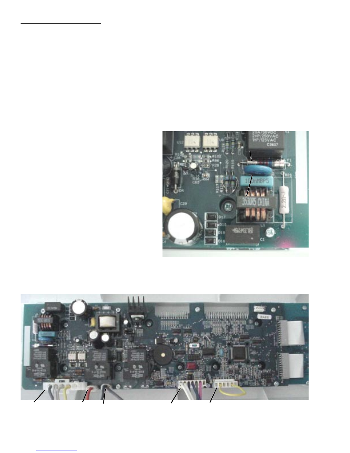
To test the sensor rod circuit:
Place the dryer in service mode and index to the rod voltage test. The rod voltage, in hundredths of a
volt, shall be displayed on the DSSD. Open the door and touch the rods with your hands and view the
DSSD. The voltage displayed on the DSSD should diminish, indicating that the capacitor is discharging
properly . No change on the DSSD indicates that either the rods are not connected to the board, an open
exists in the sensor rod circuit, or there is some other problem on the board. When the rods are
released, the voltage displayed on the DSSD should increase. The sensor rods come as part of the air
duct assembly .
Note: W ait at least 45 seconds before repeating the test to allow the capacitor to charge fully .
Electronic Control Board
The electronic control board consists of 2 circuit
boards connected by 2 ribbons. The boards are
attached to the back of the control panel and
control all washer functions. The boards are
replaced with the control panel as an assembly .
If a faulty board is suspect, check for continuity
across the fuse and visually inspect the surge
protector mounted on the board. If no continuity
is read across the fuse or if the surge protector
appears burnt or damaged, replace the board.
Caution:
FuseFuse
Surge
Surge
Protector
Protector
• When replacing the control panel, remove
the protective coating from the overlay prior
to power-up to prevent ESD from damaging
the new board.
• T o prevent electrostatic discharge, ground
yourself to the washer cabinet or use an
ESD wristband.
J2
16
J
J3
– 28 –
J5
Page 31
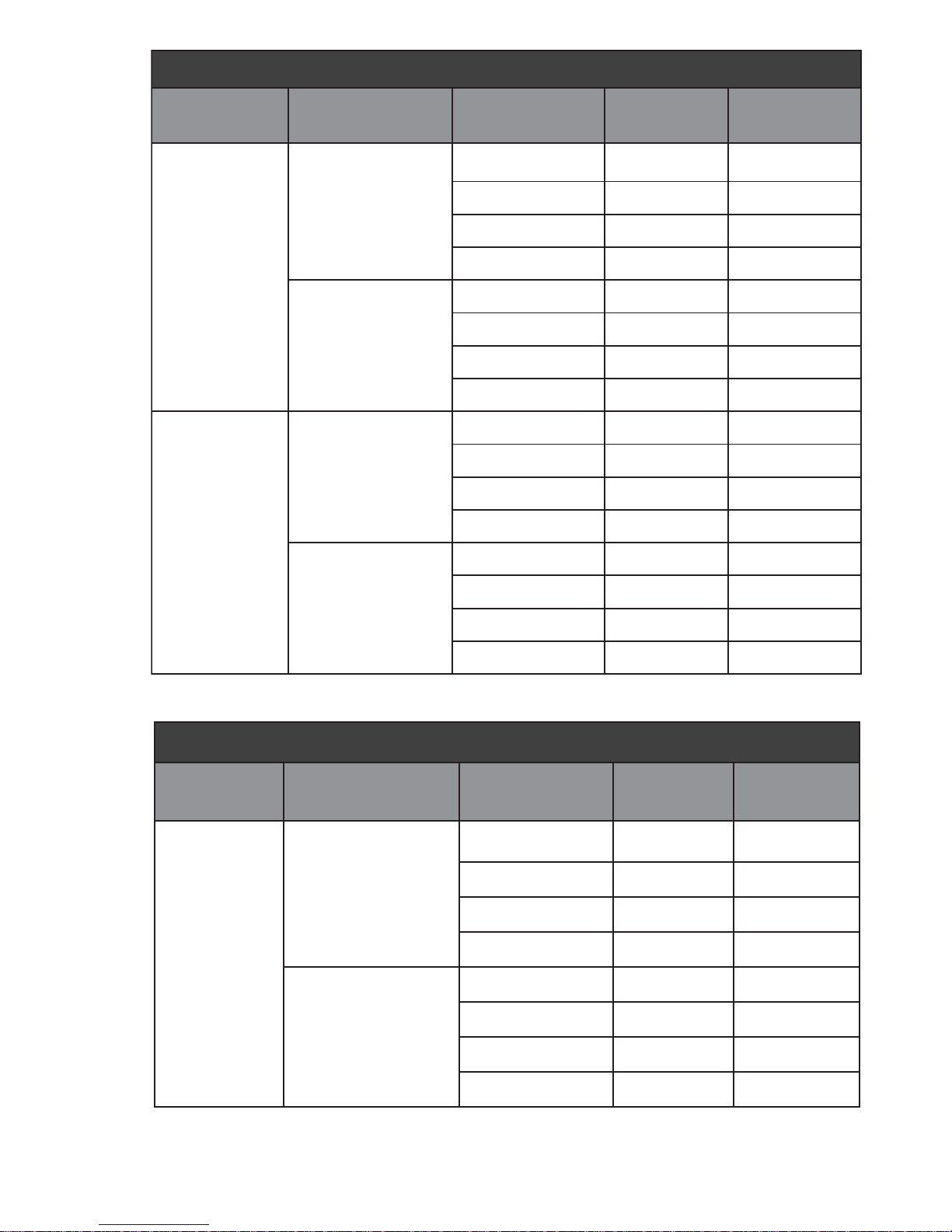
)cirtcelE(stniopteSerutarepmeT
ecruoStaeH
cirtcelE
lioCrennI
cirtcelE
lioCretuO
erutarepmeT
tniopteS
teltuO
telnI
teltuO
taeH
gnitteS
woLartxEF°201F°701
woLF°711F°421
muideMF°721F°331
hgiHF°031F°241
woLartxEF°251F°251
woLF°102F°342
muideMF°022F°352
hgiHF°522F°072
woLartxE00
woL611911
muideM521821
hgiH431731
woLartxE00
woL
tniopteS
tniopteShgiH
woL671971
telnI
muideM102402
hgiH722032
)saG(stniopteSerutarepmeT
ecruoStaeH
erutarepmeT
tniopteS
gnitteStaeH
woLartxEF°201F°701
woLF°711F°421
teltuO
muideMF°721F°331
hgiHF°031F°241
saG
woLartxEF°251F°251
woLF°102F°342
telnI
muideMF°022F°352
woL
tniopteS
hgiH
tniopteS
hgiHF°522F°072
– 29 –
Page 32
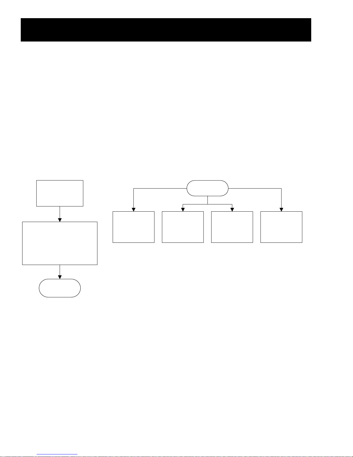
Service Mode
Service Mode
Service Mode enables individual machine functions to be selected and performed apart from the unit’s
normal operation. Field Service Mode also allows error codes to be displayed.
T o enter Service Mode:
1. T urn the unit of f at the POWER pad.
2. Remove power to the unit by unplugging it for 15 seconds.
3. Restore power. Within 30 seconds of power-up, simultaneously press and hold the POWER and
the ST A RT pads for 3 seconds.
When Service Mode is entered, the control panel will display the dryer model code. (See
Model Codes chart.)
Enter Service Mode
Remove power
to the unit.
Press the
Restore power to the unit.
Within 30 seconds of power-
up, simultaneously press
and hold the POWER and
START pads for 3 seconds.
Service Mode
Service Mode can be exited in 4 ways:
1. Press the STOP pad.
STOP pad.
Exit Service Mode
Service Mode
Press the
POWER pad.
30-minute time
out.
Loss of power
to the
electronic
control board.
2. Press the POWER pad.
3. Unplug the unit.
4. 30-minute time-out.
– 30 –
Page 33
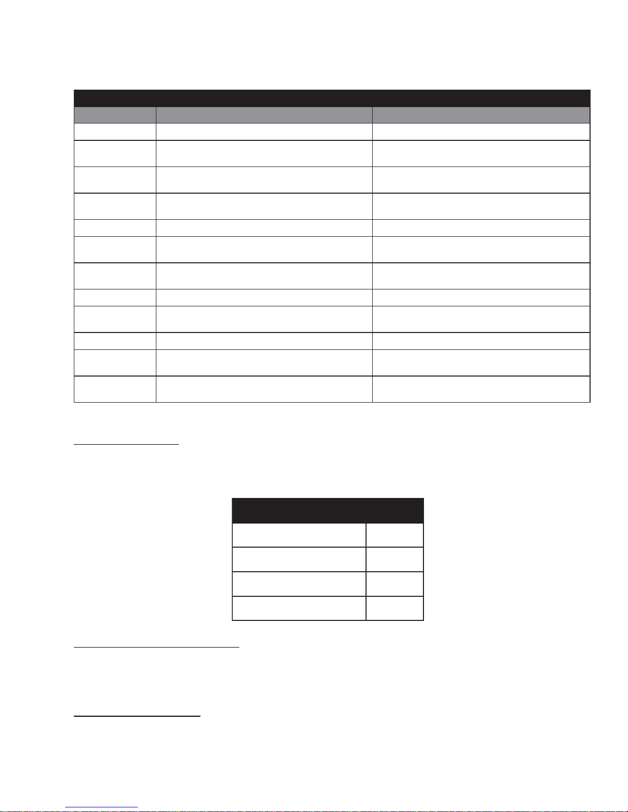
To index to the next function within Service Mode, press the CUSTOM 2 pad. To index back to the
previous function, press the CUSTOM 1 pad.
The chart below lists the order and various functions of service mode.
snoitcnuFedoMecivreS
edoM yalpsiDtluafeD tratSsserP
tseTyalpsiDledoMtrahcsedocledomeeS rebmungulprotcelesledoM
noisreVerawtfoS
tseT
MORPEEmargorP
tseT
rorrEyalpsiD
sedoC
tseTecafretnIresUdetanimulliDCLdnas'DELllA DCLnodraobrekcehcselggoT
erutarepmeTtelnI
tseT
erutarepmeTteltuO
tseT
tseThctiwSrooD
tseTegatloVdoR
tseTrotoMmurD
rennIretaeH
retuOretaeH
tseTlioC
00E tsom,deggolerasrorrefirodeggolrorreonfi
nPO -nepofi SLC desolcfi
tseTevlaVsaG/lioC
PEE
yalpsidlliW.F°59 nPO .F°572nahtretaergfi
yalpsidlliW.F°08woleb nPO .F°061nahtretaergfi
FOd yrtnenopu
FOi )cirtcele(ffo=
FOG )sag(ffo=
FOo/NOo
rebmunnoisreverawtfostigideerhT
yalpsidlliwedoctnecer
yalpsidlliW.F°nierutarepmettelnItnerruC OL wolebfi
yalpsidlliW.F°nierutarepmetteltuotnerruC OL fi
egnahcoN
nisdorgnisneserutsiomehtfoegatlovehtsyalpsiD
tlovafoshtderdnuh
egnahcoN
rotometavitcA
rebmunMORPEEtigid2dnaE
hsalfmorfMORPEEsmargorpeR
dnaedocrorredeyalpsidsraelC
edocrorretnecertsomtxensyalpsid
noitareporotomdnagnitaehsetaitinI
noitareporotomdnagnitaehsetaitinI
syalpsid;)reyrdcirtcele(liocretaehrennisetavitcA FOi
syalpsid;)reyrdsag(evlavsagsetavitcA Oo n
)reyrdcirtcele(liocretaehretuosetavitcA
Dryer Model Codes
The model code shall be displayed on the DSSD upon entering the Model Display Test.
Pressing the ST AR T pad while in the Model Display Test will display the model selector group.
Software Version Number Test
Upon entering the Software V ersion Number T est, the 3 digit software version number will be displayed
on the DSSD. When the ST A R T pad is pressed and held, the appliance will display E and the 2 digit
EEPROM version number on the DSSD.
Program EEPROM Test
Upon entering the program EEPROM test, EEP will be displayed on the DSSD. The appliance shall
reprogram the EEPROM from flash if the ST AR T pad is pressed during the test. A (key press) beep will
sound after successfully reprogramming EEPROM. The appliance shall display Err on the DSSD and
sound a warning beep if the EEPROM can not be reprogrammed.
sedoCledoMreyrD
cirtcelEDCLErS
saGDCLGrS
cirtcelEDCL-noNErJ
saGDCL-noNGrJ
– 31 –
Page 34
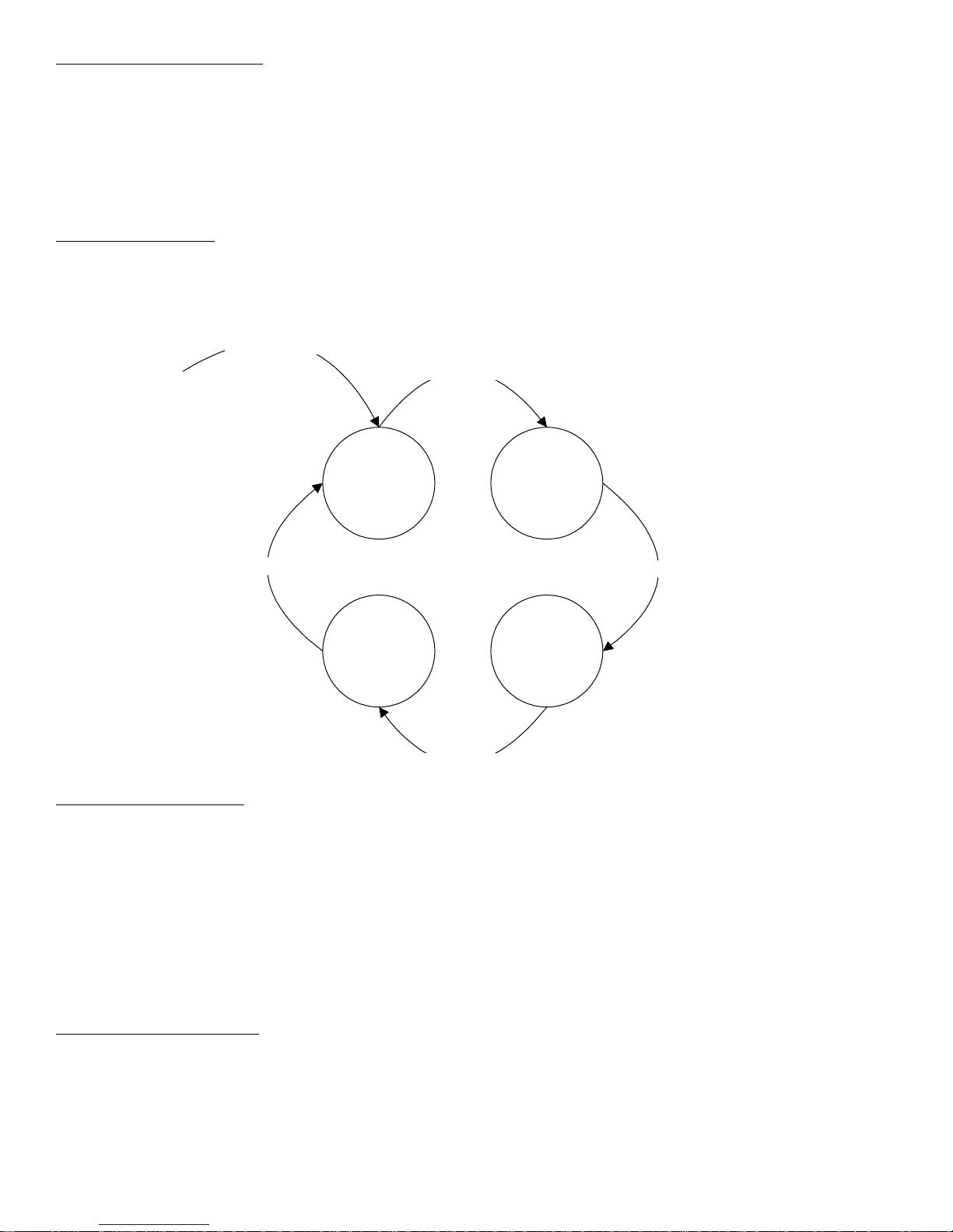
Display Error Codes Test
Upon entering the Display Error Codes T est, the most recent error code recorded in the fault log will be
displayed on the DSSD. If no errors are recorded in the fault log, E00 will be displayed. Pressing
ST A RT will clear any displayed error codes from the fault log and cause the next most recent error code
recorded to be displayed.
After clearing all errors from the fault log, the appliance shall display E00 on the DSSD.
User Interface Test
Upon entering the User Interface Test, all LED’ s and the LCD’s (LCD models only) will be illuminated.
The LCD model will turn on the LCD backlight and display a 1x1 checkerboard pattern upon entry .
Pressing the ST AR T pad will scroll the LCD through the display patterns as defined in the diagram
below.
Enter User Interface Test
Press Start Key
1 X 1
Checkerboard
Press Start Key
All Pixels Off All Pixels On
Press Start Key
1 X 1
Reverse
Checkerboard
Press Start Key
Inlet Temperature Test
Upon entering the Inlet Air T emperature T est, the inlet air sensor temperature in degrees Fahrenheit will
be displayed on the DSSD. If the measured temperature is less than 95 °F , LO will be displayed. If the
measured temperature is greater than 275 °F , OPn shall be displayed on the DSSD.
Pressing the ST AR T pad while in the Inlet Temperature Test will initiate heat and drive motor operation.
The ST AR T pad should be pressed to increase the inlet air temperature before testing the inlet
temperature sensor .
The Inlet T emperature T est displays the inlet air temperature sensor reading. It does not include room
air temperature.
Outlet Temperature Test
Upon entering the Outlet Air T emperature T est, the outlet air sensor temperature in degrees Fahrenheit
will be displayed on the DSSD. If the measured temperature is less than 80 °F , LO will be displayed on
the DSSD. If the measured temperature is greater than 160 °F , OPn shall be displayed on the DSSD.
Pressing the ST AR T pad while in the Inlet T emperature T est function will initiate heat and drive motor
operation. The ST A RT pad should be pressed to increase the outlet air temperature before testing the
outlet temperature sensor .
– 32 –
Page 35

Door Switch T e s t
Upon entering the Door Switch Test, OPn will be displayed on the DSSD if the door switch is in the open
position. If the door switch is in the closed position, CLS will be displayed.
Rod V oltage Test
Upon entering the Rod V oltage Test, the voltage of the moisture-sensing rods will be displayed in
hundredths of a volt on the SDDS. (See Sensor Rod Circuit.)
Drum Motor Test
Upon entering the Drum Motor T est, dOF will be displayed on the DSSD. Pressing ST AR T will activate
the drum motor and change the DSSD display to dOn. The dryer shall turn off the drum motor when
the Drum Motor T est has been exited.
Heater Inner Coil/Gas V alve Test
Upon entering the Heater Inner Coil/Gas V alve T est, the DSSD will display iOF, indicating the inner
heater is off (electric models) or GOF, indicating the gas valve is of f (gas models).
Pressing the ST AR T pad will activate the inner heater (electric models) or the gas valve (gas models)
and activate the motor . The DSSD display will change to iOn (electric models) or GOn (gas models),
indicating that the heater or gas valve is on. The dryer shall turn off the heater/gas valve and drum
motor when the Heater Inner Coil/Gas V alve T est has been exited.
Heater Outer Coil Test (Electric Models)
Upon entering the Heater Outer Coil Test, the DSSD will display oOF, indicating the outer heater coil is
off.
Pressing the ST AR T pad will activate the outer heater (electric models) and motor . The DSSD display
will change to oOn, inidcating the heater is on. The dryer shall turn the heater and drum motor off when
the Heater Outer Coil T est has been exited.
– 33 –
Page 36
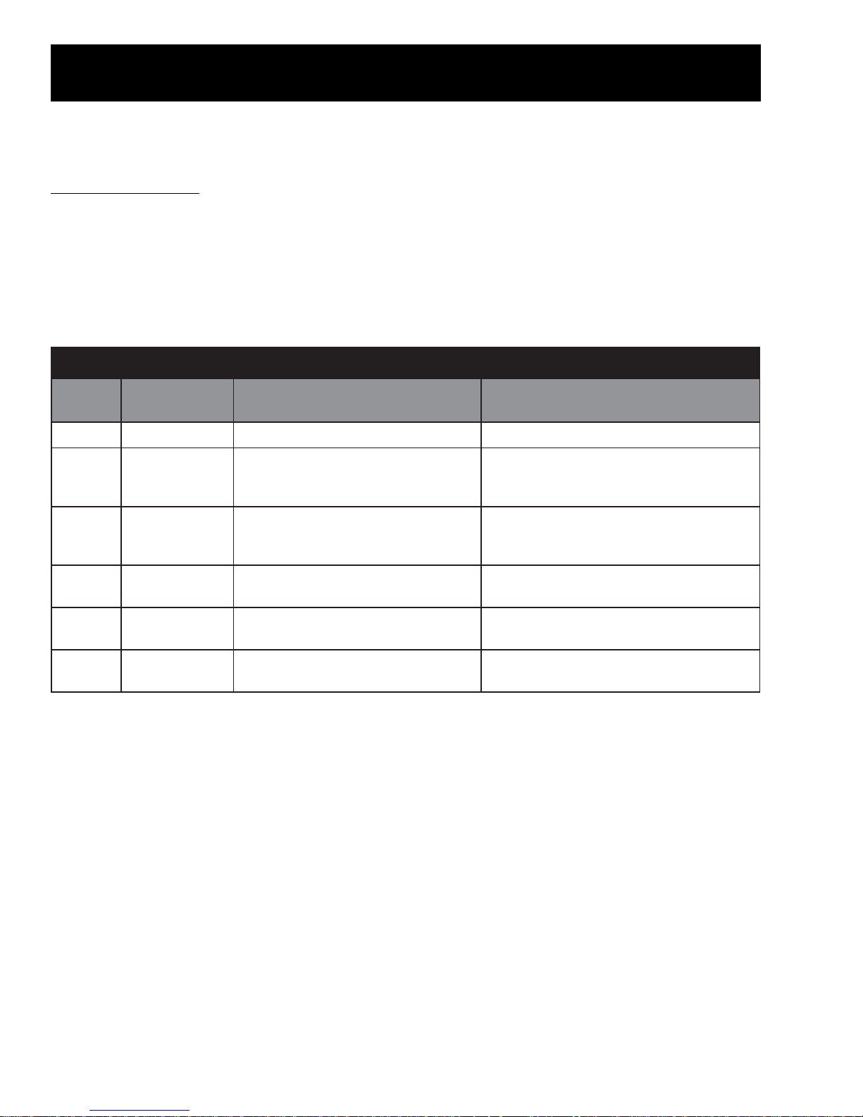
Error Codes
Refer to steps below to check error codes. Refer to the Error Codes table for a listing and description of
all error codes.
To check error codes:
1. Enter field service mode.
2. Index to the Error Codes function using the CUSTOM CYCLE 2 pad.
• If an error code is present, the error code will display immediately . If there is more than one
error, pressing the ST AR T pad will clear the displayed error code from the fault log and cause
the next most recent error to be displayed.
sedoCrorrE
yalpsiD
00EllArorrEoNlamroN
20E
05E
06E
16E
26E
/noitcnuF
rorrE
egatloVdoR
rorrE
cinortcelE
rorrElortnoC
hctiwsrooD
rorrE
rotsimrehTtelnI
rorrE
teltuO
rorrErotsimrehT
melborP noituloS
.dorgnisneserutsiomdetrohsronepO
.draoblortnoc
.eruliafMORPEE
3tsaldenepotonsahhctiwsrooD
.selcycdetelpmoc
.detrohsrotsimrehttelnI
.detrohsrotsimrehtteltuO
** If the door switch has not been opened (due to failure to open the door or a faulty switch) for 3
consecutive completed cycles, the dyer will be disabled on the 4th cycle attempt. Once the switch
has opened, dryer operation will automatically be restored.
dnadorgnisneserutsiomkcehC
cinortcleleecalper,KOfI.snoitcennoc
ecivresdleifgnisuMORPEEmargorpeR
tonsimelborpfI.tseTMORPEEedom
.draoblortnoccinortceleecalperdetcerroc
fI.edomecivresgnisuhctiwsroodtseT
**.edocrorreteserdnahctiwsecalper,ytluaf
.snoitcennocdnarotsimrehttelnikcehC
.dedeensaecalperroriapeR
.snoitcennocdnarotsimrehtteltuokcehC
.dedeensaecalperroriapeR
– 34 –
Page 37
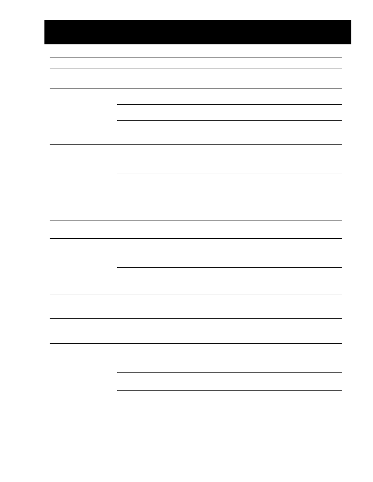
OPERATION Possible Causes What To Do
Control pads not Controls accidentally put in • Press STOP.
responding service mode
Dryer doesn’t start Control panel is “asleep” • This is normal. Press START twice to choose the last cycle
you used and to start the dryer.
Dryer is unplugged • Make sure the dryer plug is pushed completely into
the outlet.
Fuse is blown/circuit breaker • Check the building’s fuse/circuit breaker box and
is tripped replace fuse or reset breaker. NOTE: Electric dryers
use two fuses or breakers.
Dryer doesn’t heat Fuse is blown/circuit breaker • Check the building’s fuse/circuit breaker box and
is tripped; the dryer may tumble replace both fuses or reset both breakers. Your dryer
but not heat may tumble if only one fuse is blown or one breaker
tripped.
Gas service is off • Make sure gas shutoff at dryer and main shutoff are
fully open.
LP gas supply tank is empty • Refill or replace tank. Dryer should heat when utility
or there has been a utility service is restored.
interruption of natural gas
(gas models)
Dryer shakes or Some shaking/noise is normal. • Move dryer to an even floor space, or adjust leveling legs
makes noise Dryer may be sitting unevenly as necessary until even.
Inconsistent drying times Type of heat • Drying time will vary according to the type of heat used.
If you recently changed from an electric to a gas
(natural or LP) dryer, or vice versa, the drying time
could be different.
Type of load and • The load size, types of fabric, wetness of clothes and the
drying conditions length and condition of the exhaust system will affect
drying times.
No numbers displayed Dryer is continuously • This is normal. When the dryer senses a low level of
during cycle, only lights monitoring the amount of moisture in the load, the dryer will display the dry time
moisture in the clothes remaining.
Time Remaining The estimated time may change • This is normal.
jumped to a when a smaller load than usual
lower number is drying
Clothes are still wet The door was opened mid-cycle. • A dry cycle must be reselected each time a new load
and dryer shut off The load was then removed from is put in.
after a short time the dryer and a new load put in
without selecting a new cycle
Small load • When drying only a few items, choose SPEED DRY or
TIMED DRY.
Load was already dry except • Choose SPEED DRY or TIMED DRY to dry damp collars
for collars and waistbands and waistbands. In the future, when drying a load with
collars and waistbands, choose MORE DRY.
Troubleshooting Guide
– 35 –
Page 38
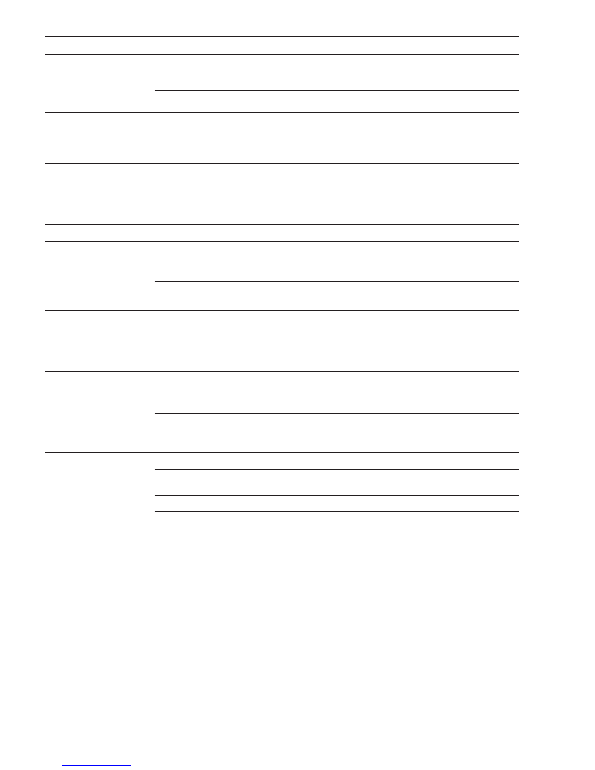
OPERATION Possible Causes What To Do
The DRY dryness level Load consists of a mixture • When combining heavy and light fabrics in a load,
was chosen but load is of heavy and light fabrics choose MORE DRY.
still damp
Exhaust system is blocked • Inspect and clean exhaust system.
Cannot make a The DRYNESS LEVEL, TEMP • This is normal.
selection and the or OPTION that you are
dryer beeps twice trying to select is incompatible
with the chosen dry cycle
Dryer is running but The EXTEND TUMBLE • This is normal. During extended tumbling, the time
00 is displayed in option was chosen remaining is not displayed. The extended tumbling
Time Remaining option lasts approximately 20 minutes.
LAUNDRY PRACTICES Possible Causes What To Do
Clothes are wrinkled Overdrying • Select a shorter drying time.
• Remove items while they still hold a slight amount of
moisture. Select a LESS DRY or DAMP setting.
Letting items sit in dryer after •Remove items when cycle ends and fold or hang
cycle ends immediately, or use the EXTEND TUMBLE option.
Clothes shrink Some fabrics will naturally shrink • To avoid shrinkage, follow garment care labels exactly.
when washed. Others can be
safely washed, but will shrink
• Some items may be pressed back into shape after drying.
in the dryer
• If you are concerned about shrinkage in a particular
item, do not machine wash or tumble dry it.
Greasy spots on clothes Improper use of fabric softener • Follow directions on fabric softener package.
Drying dirty items • Use your dryer to dry only clean items. Dirty items can
with clean ones stain clean items and the dryer.
Clothes were not • Sometimes stains which cannot be seen when the
completely clean clothes are wet appear after drying. Use proper washing
procedures before drying.
Lint on clothes Lint filter is full • Clean lint screen before each load.
Improper sorting • Sort lint producers (like chenille) from lint collectors
(like corduroy).
Static electricity can attract lint • See suggestions in this section under STATIC.
Overloading • Separate large loads into smaller ones.
Paper, tissue, etc., left in pockets • Empty all pockets before laundering clothes.
– 36 –
Page 39
LAUNDRY PRACTICES Possible Causes What To Do
Static occurs No fabric softener was used • Try a fabric softener.
• Bounce
®
Fabric Conditioner Dryer Sheets have been
approved for use in all GE Dryers when used in
accordance with the manufacturer’s instructions.
Overdrying • Try a fabric softener.
• Adjust setting to LESS DRY or DAMP.
Synthetics, permanent press • Try a fabric softener.
and blends can cause static
Collars and waistbands The dr yness monitor senses • Choose SPEED DRY or TIMED DRY to dry damp collars
still wet at end of cycle that the body of the clothes and waistbands. In the future, when drying a load with
is dry collars and waistbands, choose MORE DRY.
Clothes take too long Improper sorting • Separate heavy items from lightweight items (generally,
to dry a well-sorted washer load is a well-sorted dryer load).
Large loads of heavy fabrics • Large, heavy fabrics contain more moisture and take
(like beach towels) longer to dry. Separate large, heavy fabrics into smaller
loads to speed drying time.
Controls improperly set • Match control settings to the load you are drying.
Lint filter is full • Clean lint filter before every load.
Improper or obstructed ducting •Check installation instructions for proper
ducting/venting.
• Make sure ducting is clean, free of kinks and
unobstructed.
• Check to see if outside wall damper operates easily.
• Check the Installation Instructions to make sure the
dryer venting is correct.
Blown fuses or tripped circuit • Replace fuses or reset circuit breakers. Since most
breaker dryers use 2 fuses/breakers, make sure both are
operating.
Overloading/combining loads •Do not put more than one washer load in the dryer at
a time.
Underloading • If you are drying only one or two items, add a few items
to ensure proper tumbling.
– 37 –
Page 40
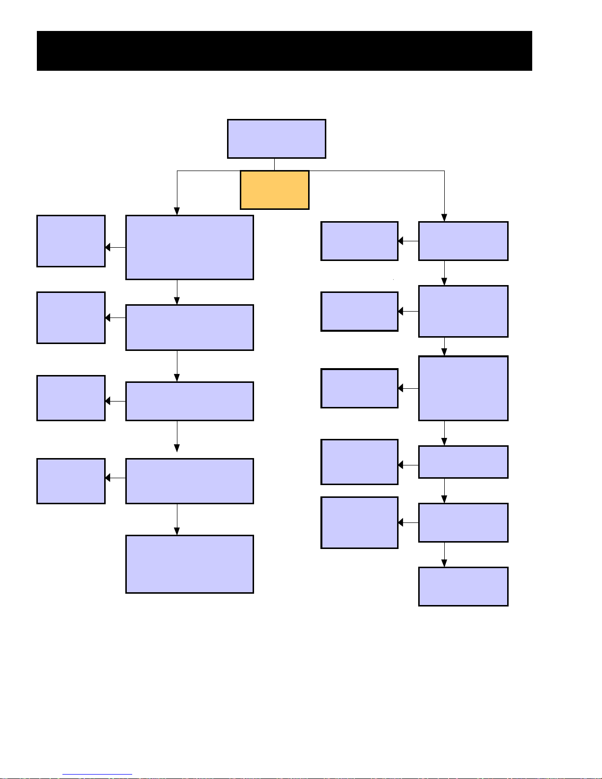
Troubleshooting Flowcharts
y
y
y
g
g
g
y
g
g
No Heat - Drum Turns
Gas Dryer
Bad connection
or defective
board.
R eplace open
t’stat or repair
wirin
R eplace
defective i
niter
R eplace Fla me
D etrector
N
Heat selected & motor running.
N
C heck for 120VAC at pin 16
on the
as valve to neutral.
Y
N
C heck Inlet safety & outle t
backup t’stats. Clo sed circuits?
Y
N
Igniter OK? 50 to 400 ohms
Y
N
Flam e Detector contacts
closed?
Ignito r Glowing?
Fix Supply
problem
R eplace Ignito r
R eplace Detector
R eplace gas
valve assemb l
Y
N
Gas Supply OK to
er?
dr
Y
Ignito r betw een 50 &
N
400 ohm s at room
tem perature?
Y
Flam e Detector
N
contacts open after
nitor on 15-90
i
seconds?
Y
G as va lve solenoid s
N
check OK?
Y
Y
Manually push motor cent rifugal
switch & ch eck f or continu it
betw een M1& M2?
– 38 –
Open wiring in
as valve circu it,
locate & repair.
N
120VAC to gas va lve
soleno ids?
Y
R eplace gas valve
assem bl
Page 41
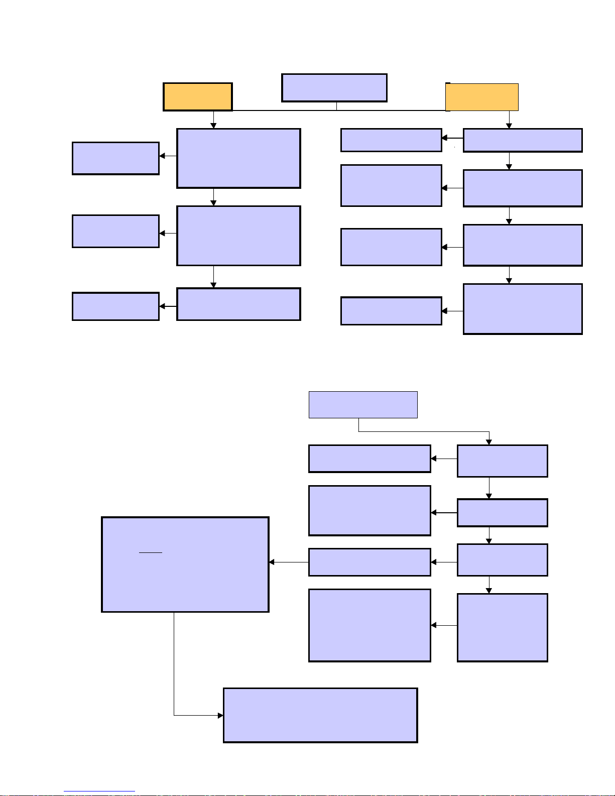
No Heat or Partial Heat - Drum T urns
g
g
y
g
g
y
g
g
y
y
y
y
y
g
g
g
y
g
g
y
Repa ir co nnec t ion
or replace board
Repa ir co nnec t ion
or replace board
Replace defective
heater
Part ial Heat
Y
With heat selected & motor
runnin
N
N
N
, ch e ck for 240 V AC
at heater rela
(J2 plu
240VAC?
With heat selected & motor
runnin
at heater rela
(J2 plu
240VAC?
Check he aters - appx 20
ohms each
.
pin 16 & L2
). Do you have
Y
, ch e ck for 240 V AC
pin 10 & L2
). Do you have
Y
Electric Dryer
House supply problem
Terminal block, wirin
pro ble m, inle t sa fety
or outlet backup t’stat
Repa ir co nnec t ion or
replace def ective
heaters
Replace defective
motor
Dryer Will Not Run
No Heat
Y
N
240VAC to dryer?
Y
Check for 240VAC at L2
N
(J2 plu
rela
Check heaters at heater
N
rela
40 ohms ?
Manually push motor
centrifugal switch & check
N
for continuit
&M2?
) & L1(heater
)
Y
s pins 16 & 10. Appx
Y
between M1
Check resistance at J2 (m otor plug) on
control board a t 2A (Gra
Open
wires.
switch, motor & associated wiring)
(If resistance readin
moto r & id le r sw itc h a r e ok.)
Proceed to next step
? (If yes - check idler
) & DS (W)
is 2.5 ohms,
Gas Dryer
House fuse, breaker, or
outlet problem
Check L1 (Blk) & N (Y)
connect ion on board.
120VAC? (If no - repair
connection/wirin
Y
Door switch OK? (If No correct)
Check resistance at J2
(motor plu
board at 2A (Gray) & DS (W)
wires. 4 or 5 ohms indicates
open start or run windin
Replace Motor
.
)
) on c ontr o l
N
Adequate voltage
to dr
er?
Y
N
Display Lights up?
Y
N
Does motor hum?
Y
Obstruction in
blower wheel?
N
(If Yes - correct)
?
Stalled motor? (If
Replace
es -
Motor
)
Se lect “Air Dry” push the “Start” pad &
read volta
ou should read 120VAC. (If 0VAC, check
&
connect ions?)
e at the J2 plug 2A (G ray)& N (Y)
Replace Board
– 39 –
Page 42
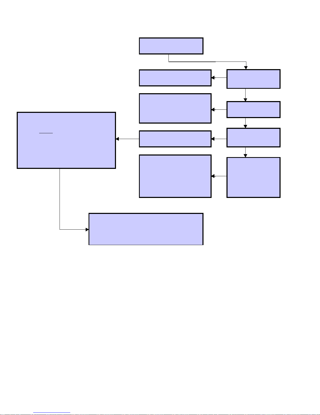
Dryer Will Not Run
Electric Dryer
Check resistance at J2 (mo tor plug) on
contro l boar d at 2A (Gray ) & DS (W/Br)
wires .
switch, motor & associated wiring)
(If resistance reading is 2.5 ohms,
mo tor & idl e r s witch ar e o k.)
Proceed to next st ep
? (If yes - check idler
Open
Select “Air Dry” push the “Start” pad &
read volt age at th e J2 plug 2A (Gray) & N (Y)
& you should read 120VAC. (If 0VAC, check
connections?)
House fuse, breaker, or
outlet problem
Veri fy Hi-lim it t’stat circui t at
L1 (J2 plug) & N (J2 plug) 120VAC? (If no - repair
connection/wiring)
Y
Door switch OK? (If No correct)
Check resistance at J2
(motor plug) on co ntrol
board at 2A (Gray ) & DS
(W/B r) wires . 4 or 5 ohms
indicat es open start or run
windi n g ?
.
Replace Board
Repl ac e Motor
N
A d eq u at e v o l tag e
to dryer?
Y
N
Display Lights up?
Y
Does motor hum?
Y
Obstruction in
blower wheel?
N
(If Y es - corre ct)
Stalle d mo tor? (If
Replace
yes -
Motor
)
– 40 –
Page 43
Notes
– 41 –
Page 44
Schematics
L2
Black
N
Yellow
Black
BlackWhite
Drum Lamp
NC
DR.O
NO
Door Switch
COM
Thermistor Assemblies
DR,C
White
Inlet
White
White
1
J3
Blue
2
3
Outlet
Gray
Gray
Blue
4
1VS
1VS
Upper Rod
Lower Rod
Pink
Pink
5
6
Green
7
M1M2
Black/Red
Yellow?Brown
run
M6 start
Drum/Blower Motor
M5 M4
Red
gray
Orange
hi-limit
Orange
1
3
2
J5
L1
transformer
N
Motor relay
Power Board
relay
heater
relay
heater
4
K3
K2
K1
Idler Switch
Gray
Gray
Purple
inner coil
outer coil
J2
L1
D
A
2
N
L2
S
White/Brown
6
5
5
4
3
2
1
10
9
Heater Housing
16
J
outlet
control
backup
Black
Black
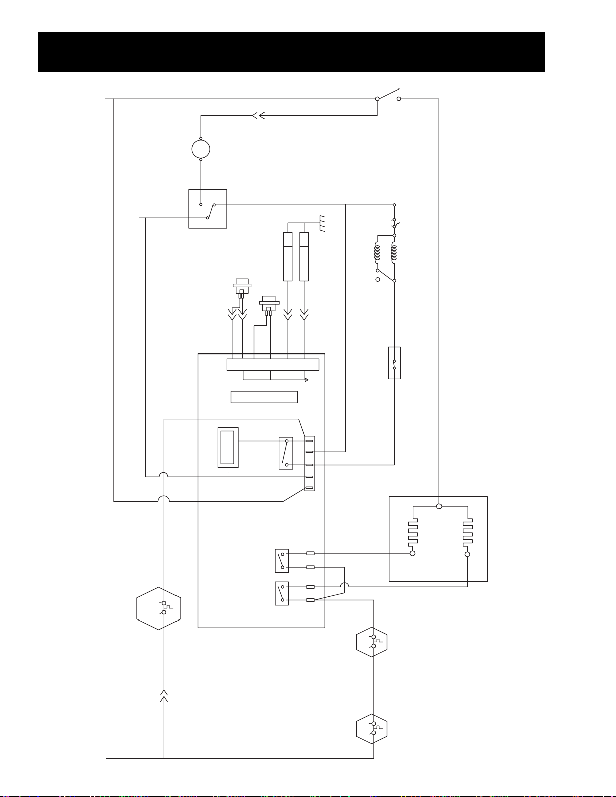
Purple
Orange
Warning: Disconnect electrical power before servicing.
Caution: Label all wires prior to disconnection. Wiring errors can cause improper and dangerous operation. V erify operation after servicing.
L1
Red
– 42 –
inlet
safety
orange
Page 45
BLACK
BLACKWHITE
DRUM LAMP
M1
M2
WHITE
DRUM/BLOWER MOTOR
YELLOW/BROWN
START
M6
M5 M4RUN
REDGRAY
IDLER SWITCH
PURPLE
N
DOTTED LINES REPRESENT
SOLDER TRACES ON PC BOARD
GANGED SWITCH
M5M4M6M1M2
23 45
1
L2 N 2A DS L1
CONNECTOR 643405-1
PURPLE
COIL
MAIN
WHITE
GAS VALVE
YELLOW/BROWN
NC
WHITE
N0
COM
DR,C
Inlet
1VS
Green
1VS
DR.0
N
DOOR SWITCH
Outlet
Upper Rod
Lower Rod
WHITE
YELLOW
WHITE
THERMISTOR ASSEMBLIES
BLUE
WHITE
WHITE
123
J3
12345
J5
L1
TRANSFORMER
N
BLUE
4
MOTOR RELAY
Gray
GRAY
5
6
Pink
PINK
6
7
345
12
2A DS L1
N
L2
BLACK
L1
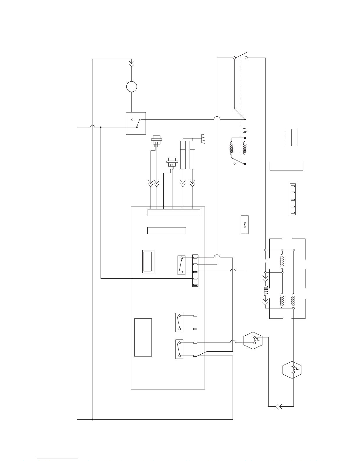
Warning: Disconnect electrical power before servicing.
Caution: Label all wires prior to disconnection. Wiring errors can cause improper and dangerous operation. V erify operation after servicing.
RELAY
SPARE
POWER BOARD
RELAY
GAS VALVE
BLACK
– 43 –
J16910
BLACK
ORANGE
INLET
SAFETY
IGNITOR DETECT
BOOSTER
ORANGE
COIL
OUTLET
BACKUP
CONTROL
COIL
YELLOW
ORANGE YELLOW SAFETY
 Loading...