

GE CP350ST1SS, JP340BM1BB, JP340BM2BB, JP346BM1BB, JP346BM2BB Installation Guide
...
Installation
30" Electric Cooktop
Instructions
I r_ ,,if you have questions, call 800.GE.CARES or visit our website at: ge.com" I
BEFORE YOU BEGIN
Read these instructions completely and carefully.
CP350, JP340, JP346, JP356, PP912, PP932, PP942,
PP944, PP945, PP950
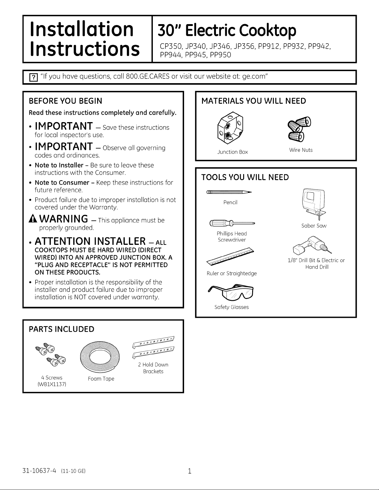
MATERIALSYOUWILL NEED
•IMPORTANT - Savetheseinstructions
for local inspector's use.
•IMPORTANT - Observeoligoverning
codes and ordinances.
• Note to Installer-Be sureto leavethese
instructionswiththe Consumer.
Junction Box Wire Nuts
TOOLS YOU WILL NEED
• Note to Consumer - Keep these instructionsfor
future reference.
• Product failure due to improper installation is not
covered under the Warranty.
_i _,_
Pencil
-_ WARNING - Thisappliance mustbe
properly grounded.
•ATTENTION INSTALLER - ALL
COOKTOPS MUST BE HARD WIRED (DIRECT
WIRED) INTO AN APPROVED JUNCTION BOX. A
"PLUG AND RECEPTACLE" IS NOT PERMITTED
ON THESE PRODUCTS.
• Proper installation is the responsibility of the
installer and product failure due to improper
installation is NOT covered under warranty.
Phillips Head
Screwdriver
Ruler or Straightedge
Safety Glasses
SaberSaw
1/8"DrillBit& Electricor
HandDrill
PARTS INCLUDED
2 HoldDown
Brackets
4 Screws
(WBlXllS7)
31-10637-4 (11-1oGE) 1
Foam Tape
Installation Instructions
IMPORTANT SAFETY INSTRUCTIONS
FOR YOUR SAFETY
• For Personal Safety, remove house fuse or open
circuit breaker before beginning installation.
Failure to do so could result in serious injury or
death.
• Be sure your cooktop is installed properly by a
qualified installer or service technician.
• To eliminate the risk of burns or fire due to
reaching over heated surface elements, cabinet
storage located above the surface units should
be avoided. If cabinet storage space is to be
provided, the risk can be reduced by installing a
range hood that projects horizontally a minimum
of 5" beyond the bottom of the cabinets. Cabinet
installation above the cooktop may be no deeper
than 13".
• Hake sure the cabinets and wall coverings
around the cooktop can withstand the
temperatures (up to 200°F) generated y the
cooktop.
• The cooktop should be easy to reach and lighted
with natural light during the day.
• Always disconnect the electrical service to
the cooktop before repairing or servicing the
cooktop. This can be done by disconnecting the
fuse or circuit breaker. Failure to do this could
result in a dangerous or fatal shock. Know where
your main disconnect switch is located. If you do
not know, have your electrician show you.
ELECTRICAL REQUIREMENTS
This appliance must be supplied with the proper
voltage and frequency, and connected to an
individual, properly grounded branch circuit,
protected by a circuit breaker or a time delay fuse
as noted on name plate.
We recommend you have the electrical wiring and
hookup of your cooktop connected by a qualified
electrician. After installation, have the electrician
show you where your main cooktop disconnect is
located.
Wiring must conform to National Electrical Code.
You can get a copy of the National Electrical Code,
ANSI/NFPA No. 70-Latest Edition, by writing:
National Fire Protection Association
Batterymarch Park
Quincy, IVlA 02269
The cooktop conduit wiring is approved for copper
wire connection only, and if you have aluminum
house wiring, you must use special UL approved
connectors for joining copper to aluminum.
You must use a two-wire, three conductor 208/2/40
VAC, 60 Hertz electrical system. A white (neutral)
wire is not needed for this unit. The cooktop must
be installed in a circuit that does not exceed 125
VAC nominal to ground.
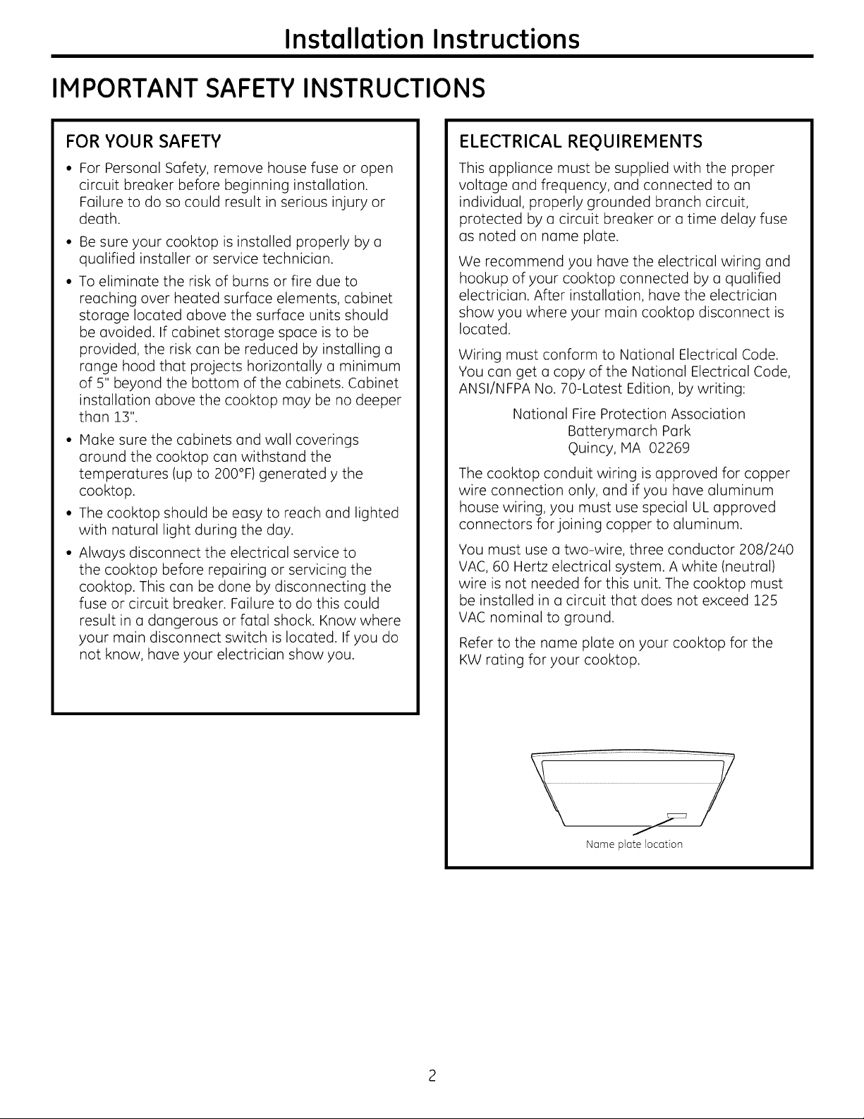
Refer to the name plate on your cooktop for the
KW rating for your cooktop.
Name plate location
Installation Instructions
PRE-INSTALLATION CHECKLIST
--&WAR NIN6 - Theelectricalpowerto
the cooktop supply line must be shut off while
connections (]re being made. Failure to do so
could result in serious injury or death.
F_l When preparing cooktop opening, make sure
the inside of the cabinet and the cooktop do
not interfere with each other. (See section on
preparing the opening.)
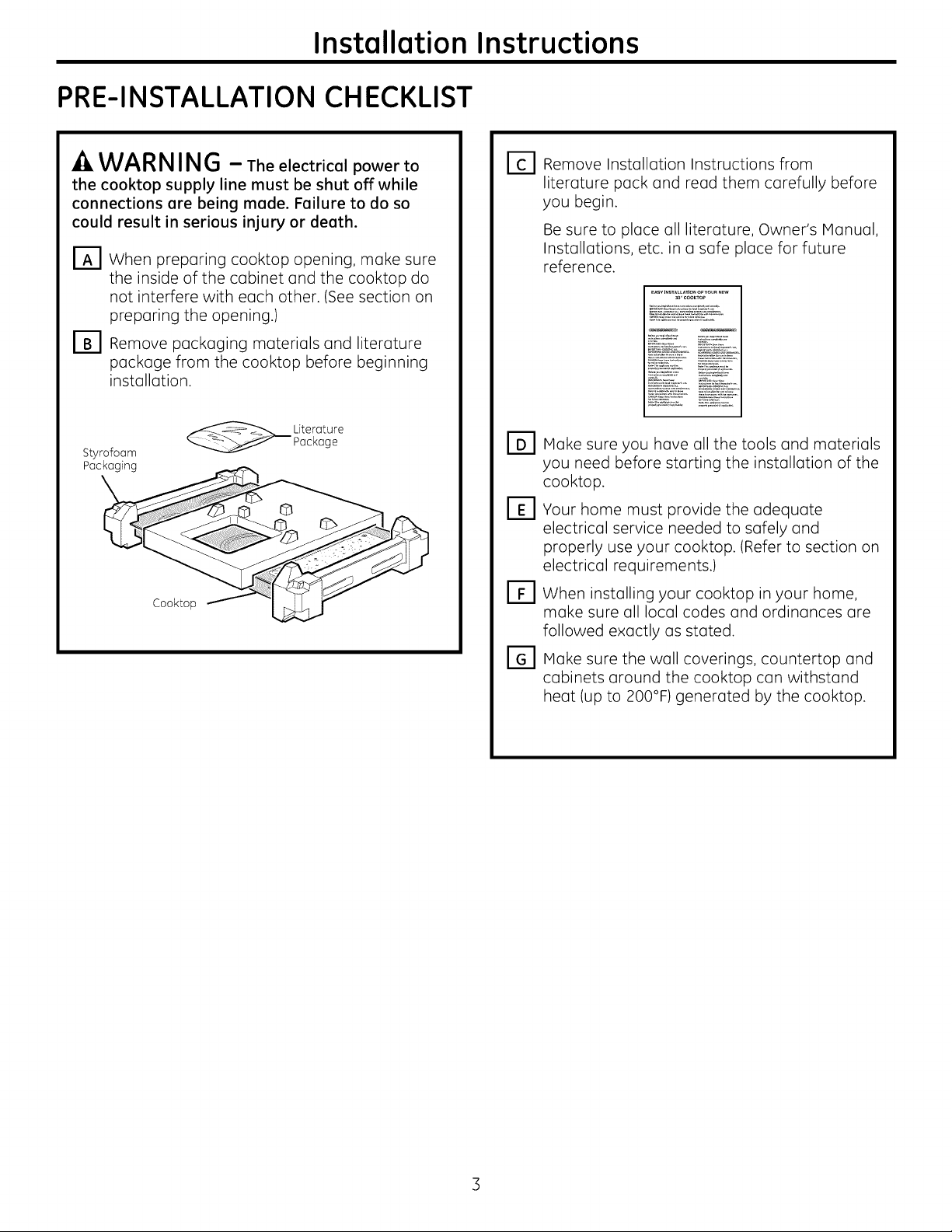
r_ Remove packaging materials and literature
package from the cooktop before beginning
installation.
_ iterature
Styrofoam
Packaging
Cooktop
Package
©
db
_] Remove Installation Instructions from
literature pack and read them carefully before
you begin.
Be sure to place all literature, Owner's Manual,
Installations, etc. in a safe place for future
reference.
_AsYINSTAL_ATIO_OFYOU_mEW
SO¸'C_KTO_
Make sure you have all the tools and materials
you need before starting the installation of the
cooktop.
B]
Your home must provide the adequate
electrical service needed to safely and
properly use your cooktop. (Refer to section on
electrical requirements.)
[B
When installing your cooktop in your home,
make sure all local codes and ordinances are
followed exactly as stated.
Make sure the wall coverings, countertop and
cabinets around the cooktop can withstand
heat (up to 200°F) generated by the cooktop.
Installation Instructions
PREPARING THE OPENING
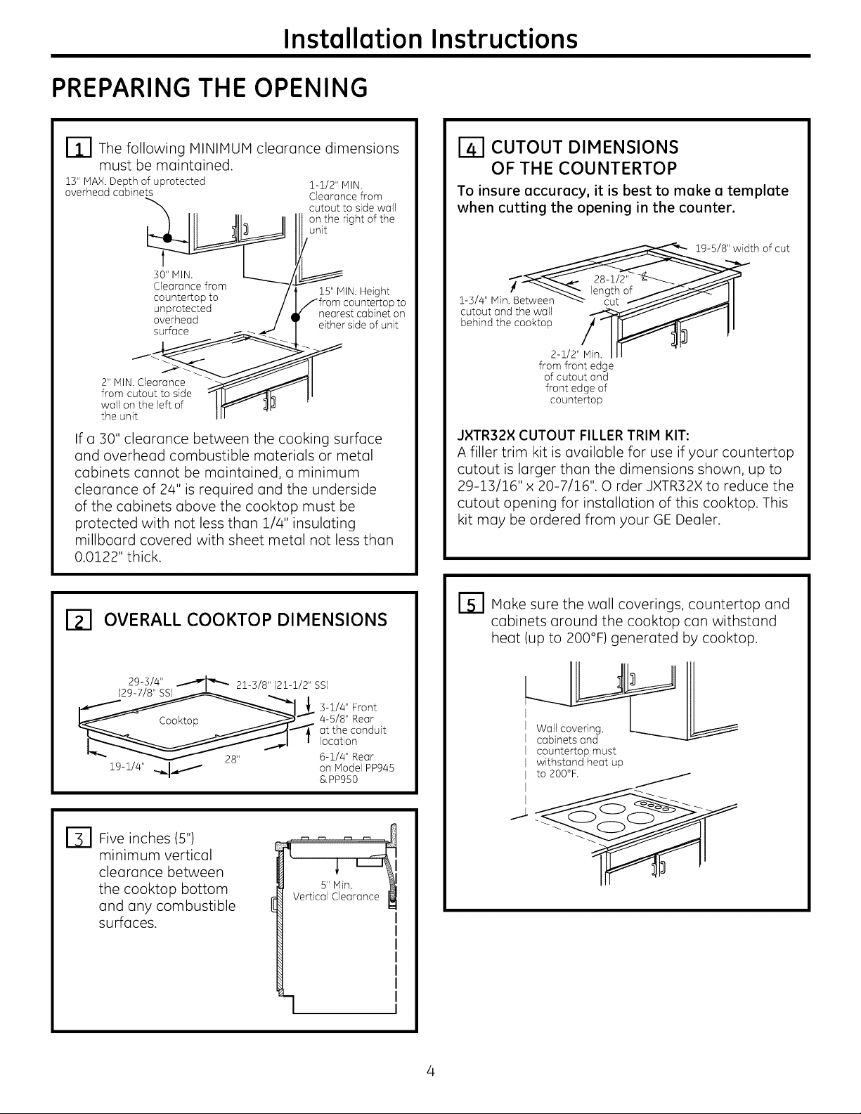
rll The following MINIMUM clearance dimensions
must be maintained.
13" MAX. Depth of uprotected 1-1/2" MIN.
overhead cabinets Clearance from
cutout to side wall
on the right of the
unit
30" IV]IN.
Clearance from 15" MIN. Height
countertop to countertop to
unprotected nearest cabinet on
overhead either side of unit
surface
2" IV]IN.Clearance
from cutout to side
wall on the left of
the unit
If a 30" clearance between the cooking surface
and overhead combustible materials or metal
cabinets cannot be maintained, o minimum
clearance of 24" is required and the underside
of the cabinets above the cooktop must be
protected with not less than 1/#' insulating
millboard covered with sheet metal not less than
0.0122" thick.
CUTOUT DIMENSIONS
OF THE COUNTERTOP
To insure accuracy, it is best to make a template
when cutting the opening in the counter.
th of cut
1-3//4 'l Min. Between _" cut I_ " _1
cutout and the wall __ _ I
2-1/2 _Nin. III
from front edge
of cutout and
front edge of
countertop
JXTR32X CUTOUT FILLER TRIM KIT:
A filler trim kit is available for use if your countertop
cutout is larger than the dimensions shown, up to
29-13/16" x 20-7/16". O rder JXTR32X to reduce the
cutout opening for installation of this cooktop. This
kit may be ordered from your GE Dealer.
OVERALL COOKTOP DIMENSIONS
29-3/4"
_._ -1/4" Front
19-1/4" .._1_......._ on Model PP945
Five inches (5")
B]
minimum vertical
clearance between
the cooktop bottom
and any combustible
surfaces.
__I
-_r r''" 21-3/8" (21-i/2" SS)
-"_ at the conduit
Vertical Clearance
4-5/8" Rear
location
6-1/4" Bear
&PP950
l i
5"Min. I ' I_
]
Make sure the wall coverings, countertop and
cabinets around the cooktop can withstand
heat (up to 200°F) generated by cooktop.
_cWaablilnCe_sVearinndg'
countertop must
withstand heat up
to 200°F.
Installation Instructions
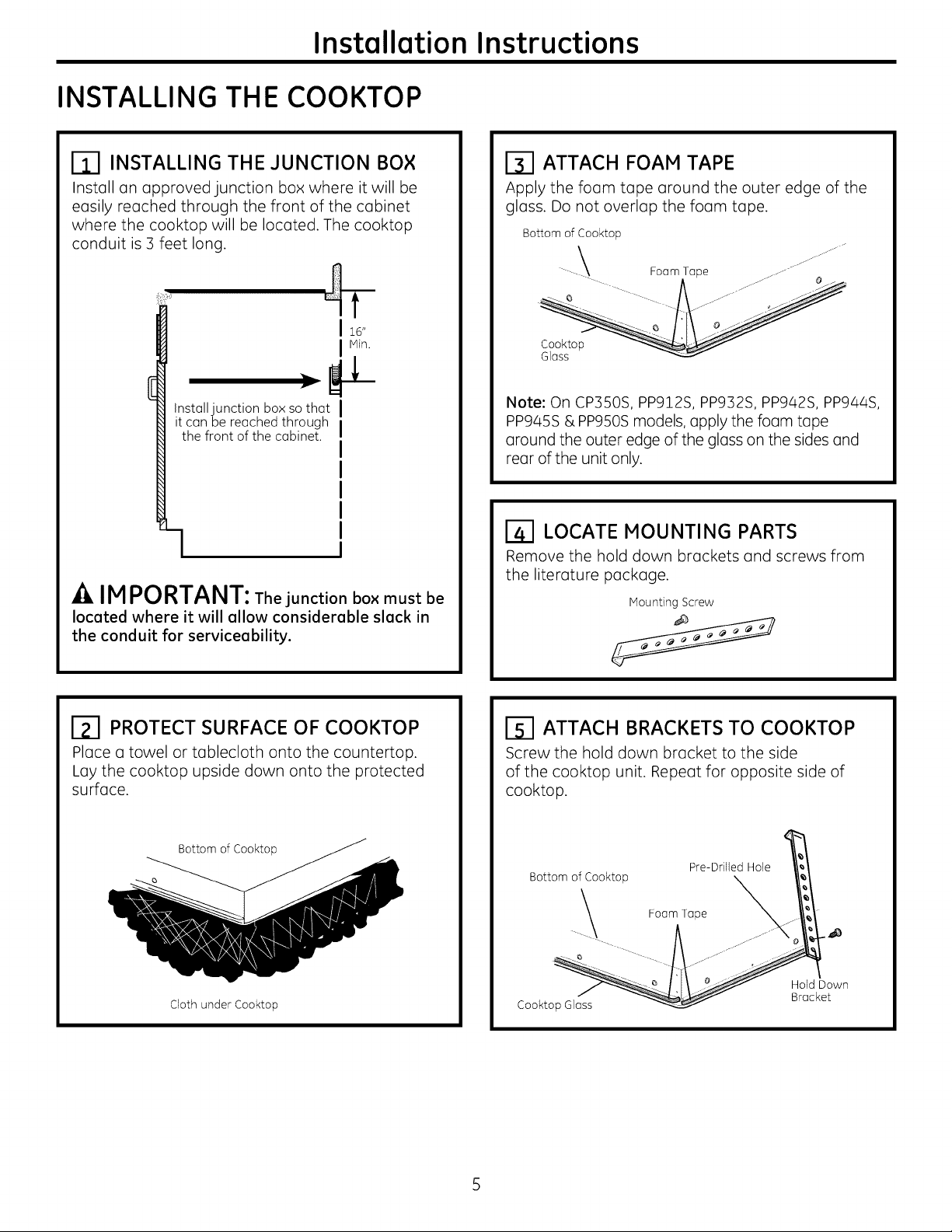
INSTALLING THE COOKTOP
rim INSTALLING THE JUNCTION BOX
Install an approved junction box where it will be
easily reached through the front of the cabinet
where the cooktop will be located. The cooktop
conduit is 3 feet long.
F
16"
Min.
_L
Install junction box sothat
it can be reached through
the front of the cabinet
-1
A IMPORTANT: The junction box must be
located where it will allow considerable slack in
the conduit for serviceability.
ITl ATTACH FOAM TAPE
Apply the foam tape around the outer edge of the
glass. Do not overlap the foam tape.
Bottom of Cooktop
- - -.. Foam Tape .---- ...........'"e z
Note: On CP350S, PP912S, PP932S, PP942S, PP944S,
PP945S & PP950Smodels, apply the foam tape
around the outer edge of the glass on the sides end
rear of the unit only.
LOCATE MOUNTING PARTS
Remove the hold down brackets and screws from
the literature package.
Mounting Screw
ITl PROTECT SURFACE OF COOKTOP
Place a towel or tablecloth onto the countertop.
Lay the cooktop upside down onto the protected
surface.
Bottom of Cooktop_
Cloth under Cooktop
ITI ATTACH BRACKETS TO COOKTOP
Screw the hold down bracket to the side
of the cooktop unit. Repeat for opposite side of
cooktop.
Pre-Drilled Hole
Bottom of Cooktop _
Cookto cket
--_--_. l j\ _i_....... Id Down
 Loading...