

GE POWER LEADER DEH-210 User Manual

POWER LEADER™
PMCS 6.8 for
CIMPLICITY
©
HMI
Interface Toolkit
User’s Guide
DEH-210
GE Power Management Control System 6.8

Notice
The information contained in this document is subject to change without notice. GE makes no warranty of any
kind with regard to this material, including, but not limited to, the implied warranties of merchantability and
fitness for a particular purpose. GE shall not be liable for errors contained herein or incidental consequential
damages in connection with the furnishing, performance, or use of this material.
This document con ta ins propri etary information wh ich is protected b y copyrigh t. A ll rights are reserved. No
part of this docu ment ma y be phot ocopie d or otherwise reproduc e d without c onsen t of GE.
Copyright ©2000 by GE. Published in a limited copyright sense, and all rights, including trade secrets, are
reserved.
Document Edition - First 04/98
Second 05/99
Third 08/99
Fourth 03/00
Fifth 10/00
The foll o wing are pr od u cts of Genera l Electric Company:
POWER LEADERTM Meter Power Quality Meter (PQM) GE Fanuc Series 90/30 PLC
POWER LEADER Modbus Monitor 239 Motor Protection Relay GE Fanuc Series 90/70 PLC
POWER LEADER Electronic Power
Meter
Spectra MicroVersaTrip 369 Motor Manag em ent Relay
Enhanced MicroVersaTrip-C SR469 Motor Management Relay
Enhanced MicroVersaTrip-D SR489 Generator Management Relay
MDP Overcurrent Relay 565 Feeder Management Relay
Spectra Electronic Control Module 735 Feeder Relay
Universal R elay devices SR74 5 Trans former Ma n agement Relay
269 Plus Motor Manag em ent Relay Motor Manager II (MMII)
SR750/SR760 Feeder Management Relay
CIMPLICITY HMI is a registered trademark of General Electric Company.
DFP 100 and DFP 200 Feeder Management Relay® and Multilin 269+ Motor Management Relay® are
registered trademarks of Multilin Inc., and Multilin SR489 Generator Management Relay™ and Multilin SR745
Transformer Management Relay™ are trademarks of Multilin Inc.
Electronic Power Meter 3710, Electronic Power Meter 3720, Electronic Power Meter 7300, Electronic Power
Meter 7500, Electronic Power Meter 7600 and Electronic Power Meter 7700 are products of Power
Measurement Li mited.
US Pat Nos 5,768,148; 5,764,155; 5,862,391

Contents
Introduction 1
Welcome..............................................................................................................................1
How should I use this manual?.............................................................................................. 2
Conventions .........................................................................................................................3
About the Interface Toolkit...................................................................................................3
Installation ........................................................................................................................... 4
Configuring and Using PMCS Wizards 5
About the Wizards ................................................................................................................5
Configuring a CIMPLICITY Project for PMCS.....................................................................6
PMCS PowerBuilder - Configuring Advanced Wizards.........................................................8
Using a PMCS Wizard........................................................................................................ 20
Small Faceplate Wizards.....................................................................................................23
Large Faceplate/Tabular Wizards........................................................................................26
One-Line Wizards..............................................................................................................33
Elevation Wizards..............................................................................................................40
Floor Plan Wizards.............................................................................................................41
Annunciator Panel Wizard..................................................................................................42
Manually Configuring Wizards without using PMCS Power Builder......................15
Manually Configuring the EPM 7700 Wizard........................................................17
Sample Application...............................................................................................21
Usage.................................................................................................................... 23
Small Faceplate Configuration ..............................................................................24
Usage.................................................................................................................... 26
Special Considerations..........................................................................................26
Configuration........................................................................................................27
Usage.................................................................................................................... 33
Configuration........................................................................................................34
Circuit Breaker One-Line Wizards ........................................................................ 39
Usage.................................................................................................................... 40
Configuration........................................................................................................40
Usage.................................................................................................................... 41
Configuration........................................................................................................41
Usage.................................................................................................................... 42
Configuration........................................................................................................46
Creating Floor Plans, Elevation Views, and One-Line Diagrams 49
Introduction........................................................................................................................49
Elevation Views.................................................................................................................49
Floor Plans .........................................................................................................................51
Electrical One-Line Diagrams.............................................................................................52
PMCS Interface Toolkit Contents • i

Sample Application 59
Creating a bas ic interface....................................................................................................59
Features of GE Large Faceplate Wizards 63
About the Large Faceplate Wizards.....................................................................................63
POWER LEADER EPM.....................................................................................................64
Spectra MicroVersa Trip
Enhanced MicroVersaTrip PM-C Trip Unit......................................................................... 68
Enhanced MicroVersaTrip PM-D Trip Unit ........................................................................ 70
POWER LEADER™ Meter................................................................................................72
Spectra ECM......................................................................................................................74
MDP Digital Overcurr ent Relay..........................................................................................76
Power Quality Meter (PQM)...............................................................................................78
EPM 3710 Meter................................................................................................................80
EPM 3720 Meter................................................................................................................82
EPM 7300 Meter................................................................................................................84
EPM 7700 Meter................................................................................................................87
239 Motor Protection Relay................................................................................................89
269 Plus Motor Management Relay.....................................................................................91
SR469 Motor Management Relay .......................................................................................96
SR489 Generator Management Relay..................................................................................98
565 Feeder Management Relay.........................................................................................100
735 Feeder Relay ..............................................................................................................106
SR745 Transformer Management Relay ............................................................................107
SR750/SR760 Feeder Management Relay.........................................................................109
®
Trip U ni t .....................................................................................67
Features of Tabular Data Screen Wizards 113
Introduction......................................................................................................................113
Features of Tabular Data Screens......................................................................................113
Power Leader EPM...........................................................................................................115
Spectra MicroVersaTrip....................................................................................................116
Enhanced MicroVersaTrip-C Trip Unit .............................................................................117
Enhanced MicroVersaTrip-D Trip Unit.............................................................................118
POWER LEADER Meter................................................................................................. 119
Spectra ECM....................................................................................................................120
MDP Digital Overcurr ent Relay........................................................................................121
PQM (Power Quality Meter).............................................................................................122
Motor Manager II (MMII) ................................................................................................123
EPM 3710 Meter..............................................................................................................124
EPM 3720 Meter..............................................................................................................125
EPM 7300 Meter..............................................................................................................126
EPM 7500/7600 Meter...................................................................................................... 127
Metering Tab......................................................................................................127
Min/Max Tab......................................................................................................129
Power Quality Tab..............................................................................................130
Dema nd Tab.......................................................................................................13 1
Inputs Tab...........................................................................................................132
Setup 1 Tab.........................................................................................................133
Setup 2 Tab.........................................................................................................135
EPM 7700 Meter..............................................................................................................137
Metering Tab......................................................................................................137
Min/Max Tab......................................................................................................139
Power Quality Tab..............................................................................................140
ii • Contents PMCS Interface Toolkit

Dema nd Tab.......................................................................................................14 1
Inputs Tab...........................................................................................................142
Setup 1 Tab.........................................................................................................143
Setup 2 Tab.........................................................................................................145
Universal Relay................................................................................................................147
Metering Tab......................................................................................................147
Power Quality Tab..............................................................................................149
Prote ction Control T ab........................................................................................150
Power System Configuration Tab ........................................................................151
Transformer Tab.................................................................................................152
Elements Tab......................................................................................................153
Digital Counter Tab............................................................................................154
Virtual Inputs Tab............................................................................................... 155
Virtual Outputs Tab............................................................................................156
Contact Inputs Tab..............................................................................................157
Contact Output Tab.............................................................................................158
DCMA Tab.........................................................................................................159
Source Tabs........................................................................................................160
Dema nd Tab.......................................................................................................16 1
Line Tab.............................................................................................................162
Breaker Tab........................................................................................................163
Contact Output Current States Tab......................................................................164
Remote Temperature Detection Tab....................................................................165
Bus Tab..............................................................................................................166
239 Motor Protection Relay..............................................................................................167
269 Plus Motor Management Relay................................................................................... 168
369 Motor Management Relay..........................................................................................169
Metering Tab......................................................................................................169
Alarms Tab.........................................................................................................171
Trip Data Tab .....................................................................................................172
Trip Counter Tab................................................................................................173
Dema nd Tab.......................................................................................................17 4
Local RTD Tab...................................................................................................175
Remote RTD Tab................................................................................................176
Control Tab ........................................................................................................177
Setup Tab...........................................................................................................178
SR469 Motor Management Relay .....................................................................................179
SR489 Generator Management Relay................................................................................180
565 Feeder Management Relay.........................................................................................181
SR735 Feeder Relay.........................................................................................................183
SR745 Transformer Management Relay ............................................................................184
SR750/SR760 Feeder Management Relay.........................................................................185
DFP100 Relay..................................................................................................................187
DFP200 Relay..................................................................................................................189
Fanuc 90/30......................................................................................................................191
Fanuc 90/70......................................................................................................................191
Troubleshooting 193
EPM 3710/EPM 3720 – no data or incorrect data displayed ............................................... 193
EPM 3720 – KVAH import values incorrect .....................................................................193
Long update when changing setpoints ............................................................................... 193
PLEPM – Wrong Metering tab displayed..........................................................................194
PMCS Interface Toolkit Contents • iii

Appendix A: EPM 3720 Sliding Window Demand Keys 195
Downloading Sliding Demand Window Keys to the EPM 3720.........................................195
Appendix B: Automatic Waveform Capture and Waveform Retrieval on
EPM 3720 201
Using a setpoint to trigger waveform capture or record on the EPM 3720..........................201
Index 215
iv • Contents PMCS Interface Toolkit

Introduction
Welcome
The PMCS Interface Toolkit i s a POWER LEADER Power Manag em ent Contr ol
System (P M C S) tool that provides a cus tom toolki t to efficient ly create flexible,
accurate, and friendly user interfaces to your power management data. With the
PMCS Wizards (accurate graphical representations of power management devices
and other commonly encountered objects), you can create applications to provide a
customized interface that accurately represents physical, electrical, and geographical
plant layouts. The wizards can significantly cut new system development time,
providing results in less than an hour.
The PMCS Interface Toolkit allows you to create one-line diagrams, elevation views,
and fl oor plans that you ca n com bi ne with tabular data s cr eens and thr ee-dimensi on a l
device wizards to create a virtual representation of your facility and equipment. With
this graphical us er in terface, you a ctually see and control devices on the screen,
withou t having to mak e a trip ou t to the mete r o r tr ip unit.
The Toolkit, which consists of the CIMPLICITY
coupled with GE’s PMCS wizards, is easy to use, taking advantage of state-of-the-art
drag-and-drop technology. Wizards are provided for all the devices most commonly
used with the PMCS DDE Server. Creating a custom interface is as easy as selecting
wizards for the devices installed in a facility and placing them on the screen.
®
HMI development environment
PMCS Interface Toolkit Introduction • 1
Here’s what you’ll find in this guide:
• Chap ter 2 explains th e kinds of PMCS Wizards, th eir use and
configuration – Small Faceplate wizards, Large Faceplate wizards,
Tabular Data Screen wizards, One- Line wizards, Elevation wizards,
and Floor Plan wizards. Includes instructions on using the PMCS
Advanced Wizards, including Small Faceplates, Large Faceplates, and
Tabular Wizards.
• Chapter 3 illustrates the use of the GE wizards described in Chapter 2
to create animated displays of the facility floor plan, switchgear
elevations, and system one- line diagrams.
• Chapter 4 gives an example of application development, using the
wizards described in Chapters 2 and 3 to create an actual PMCS
application.
• Chapter 5 describes the functions available with each of the GE Large
Faceplate wizards. These wizards are accurate graphical

representations of power management devices, complete with working
controls that ar e linked to th e correspon ding devices in your facil ity.
• Chapter 6 describes the Tabular Data wizards. These wizards list the
data and setpoints of power management devices in a tabular format.
Simply point and click to select the appropriate tab of information to
display and view the related data.
The exam ples and refer ences in th is guide enabl e you to creat e cu stom inter fa ces for
your PMCS s yst em, and all ow you to access po wer manag ement data in th e wa y that
best suits you.
How should I use this manual?
How you use t his book depends on your l e vel of expertise with CI M PLICITY.
Consult the table below to determine where you should start.
If this describes you… Start here:
I’ve never seen this stuff before! What’s
CIMPLICITY HMI? What are
“Wizards”?
I’ve just op ened this package – where
do I go first?
I’m familiar with CIMPLICITY HMI
and I’d like to build a custom
application for some GE power
management devices.
The GE PMC S Wizards are already
installed on my system, I’m already
experienced with CIMPLICITY HMI ,
and I’m ready to start building custom
applications.
Just tell me about the wizards; I’m an
old pro an d ready t o go!
Refer to the document ation tha t cam e wi th your
CIMPLICITY HMI package. Start with the
introduction and tutorial sections, which will teach
you about CIMPLICITY HMI and how to use it to
create custom applications. When you understand
what wiz ards are and h ow to us e t hem, come back
here.
Go to Chapter 1, Introduction. Chapter 1 explains
what the Interface Toolkit is, what it’s good for, and
where to go after that.
Go to Chapter 1 for installation instructions, then to
Chapter 2 for descriptions of the wizards and how to
use them. Chapter 4 provides a demo of actual
application developme nt . This pack age contai ns
wizards for the power management devices
supported by GE’s PMCS software.
Turn to Chapter 2 for information on how to use the
GE PMCS Wizards, and Chapter 4 for a quick
example of application development. For detailed
descriptions of the Large Faceplate screens or the
Tabular Data screens, refer to Chapters 5 and 6
respectively.
Ski m throu gh Chap ters 2 and 3 for an overview of
what ’ s in the packag e, then Chapt er 4 for a qu ick
example of application development. Chapter 5
describes the GE Lar ge Faceplate screen s and
Chapter 6 the associated Tabular Data screens.
Conventions
2 • Introduction PMCS Interface Toolkit
You will find this book easy to use if you look for these si mple conven tions :

• Boldface type indicates the name of an item you need to select.
• Monospace type indicates an example or text that is displayed on the
screen.
• UPPERCASE type indicates a file name, command name, or acronym.
About the Interface Toolkit
The Interface Toolkit consists of the CIMPLICITY HMI development environment
and a special set of wizards developed for use with the power management devices
supported by PMCS 6.8.
PMCS Interface Toolkit Introduction • 3
Installation
To install the Interface Toolkit from the CD-ROM, refer to the instructions provided
in DEH-211, the PMCS Read This Book First . When install ing CI MPLICITY HMI
4.01, be sure to include the Advanced DDE Communications" option.
For PMCS View Nodes, be sure to install the appropriate PMCS software to support
CIMPLICITY wizard operation. A runtime view node installation provides files
needed to operate the wizards, th e wi z ard help fil es , and the Even tViewer and
Waveform client applications. Without these files, your screens will not function
corr ectly on the view node.
For WebView users, pl ease note th at the EventViewer and Waveform client
applications cannot be viewed, but all information displayed in the wizard is
available.
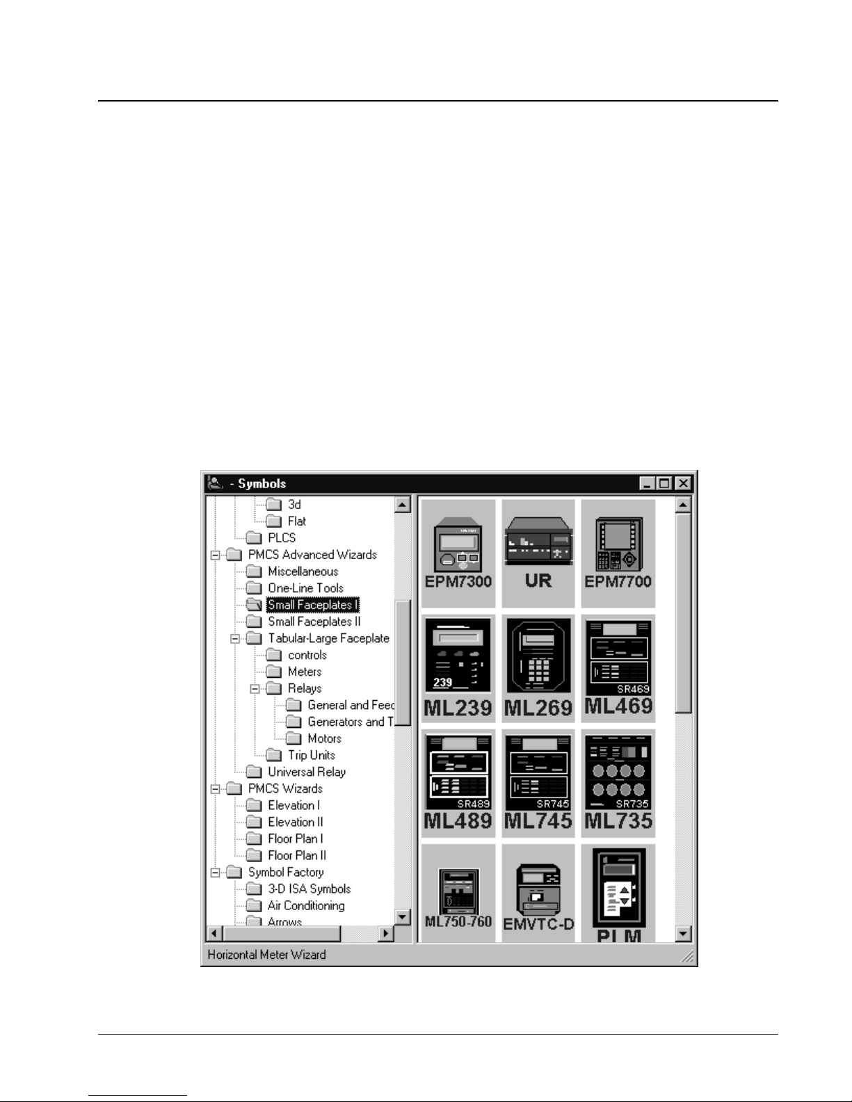
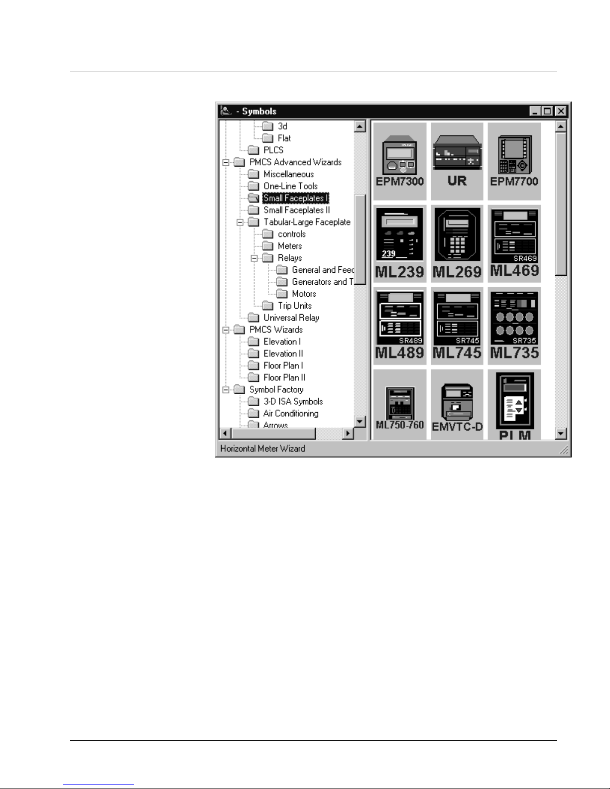
You can verify successful installation of the PMCS Wizards into CIMPLICITY HMI
by opening CimEdit, and clicking the Object Explorer button to display the symbols
library window. The PMCS Wizar ds should be li s ted in the dir ectory stru cture on the
left side of the Symbols window as shown below. If they are not, reinstall from the
PMCS CD-ROM. PMCS Advanced Wizar d s (device wizard s) are l ocat ed in the
PMCS Advanced Wizards directory; standard PMCS Wizards (such as Elevation and
Floor Plan wizards) are located in the PMCS Wizards directory.
4 • Introduction PMCS Interface Toolkit

Configuring and Using
PMCS Wizards
About the Wizards
The wizards contained in the PMCS Interface Toolkit allow you to quickly build
accurate and friendly user interfaces with CIMPLICITY HMI. In addition to the
various wizards standard with CIMPLICITY HMI development systems, the User
Scr e e n Configur a tor pr ovides five types of powerful GE wiza rds:
• GE Small Faceplate Wizards
• GE Large Faceplate/Tabular Data Wizards
• GE One- Line Tool Wizards
• GE Elev ation Wiza rds
• GE Floor Plan Wizar d s
PMCS Interface Toolkit Configuring and Using PMCS Wizards • 5

Configuring a CIMPLICITY Project for PMCS
Using the wizards is straightforward. The procedure outlined in this section describes
how to place and configure a PMCS wizard in CIMPLICITY HMI. Later sections
describe using/testing a wizard and go further into describing each kind of wizard.
1. From CIMPLICITY HMI, create a new project by clicking the New Project
button or selecting File: New Project. The New Project window appears:
2. Enter the Project Name and select a directory wh ere the project s hould be st ored
(usually in the cimplicity\hmi\projects\ ). Under Options, select
PMCS Power Builder. Finally, click the Create button to write the project file to
disk and open the Project Properties window:
6 • Configuring and Using PMCS Wizards PMCS Interface Toolkit
3. In the Project Properties window (Options tab), select the Enable project
broadcast checkbox if you will be using CIMPLICITY HMI view nodes.
Make sure the Computer name field matches the name of the host machine.
Disregard the Startup Timeout field and the General tab. Select OK to
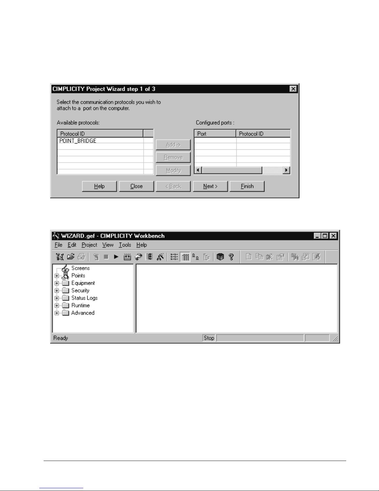
open the CIMPLICITY HMI Project Wizard:
4. In the CIMPLICITY Project Wizard step 1 of 3 window, choose Finish to
complete the project setup.
5. The CIMPLICITY W orkbench is displayed as shown be low:
PMCS Interface Toolkit Configuring and Using PMCS Wizards • 7
Double-click PMCS Power Builder to begin adding devices, and refer to PMCS
PowerBuilder - Configuring Advanc ed Wizar ds in the following section for details
on placing a PMCS Advanced Wizard in a CIMPLICITY project.
PMCS PowerBuilder - Configuring Advanced Wizards
PMCS Power Builder is a powerful tool to drastical reduce development time,
enabling you to quickly and easily add many devices to a new CIMPLICITY project.
Besides enhancing your productivity as a developer, PMCS Power Builder also
allows you to create more efficient applications which use fewer system resources
and enjoy greater performance. This is due to PMCS Power Builder's integration
with the PMCS Advanced Wizards. These wizards employ tech nology and
configuration techniques that take advantage of the power of CIMPLICITY HMI
version 4.01. The PMCS Advanced Wizards use a two-step configuration process
where the device dat a points are configur ed separatel y from the graphi cal portion of
the wizards. This section explains the procedures for configuring and using these
new wizards.
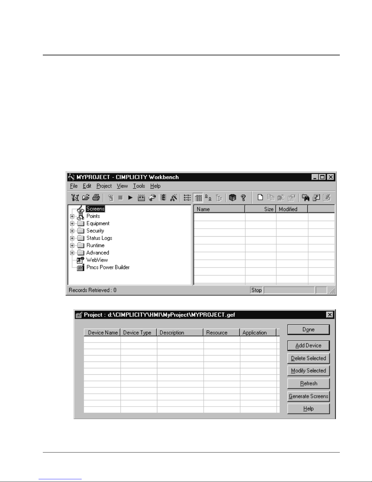
Beginning at the CIMPLICITY Workbench, double-click the PMCS Power Builder
option to begin adding devices to this project.
8 • Configuring and Using PMCS Wizards PMCS Interface Toolkit
The PMCS Power Builder tool appear s:
The command buttons displayed in the PMCS Power Builder window are:
Add Device – use this button to create a new device in your application. You can
also a d d a devi ce by double clicking an y empty line in the device information s ection
of the PowerBuilder screen, or right clicking and selecting "Add" from the drop
down menu.
Modify Selected – use this button to change the Description, Resource, an d
application information for an existing (selected) device. You can also modify a
device’s configuration by double-clicking a listed device, or by right-clicking an
exist ing device and selecting "Modify Sel ect ed" from the drop down men u. Device
Name an d Devi ce Type cann ot be m od ified once a device is cr eated. If you need to
chang e the device na me or device type, you must del ete the sel ected device and add
a new one.
Delete Selected – use this button to completely remove the selected device and its
points from the project. You also delete a device by right clicking and selecting
"Delete S elected" from the drop d own menu.
Refresh – use this button to refresh the display of devices in the PowerBuilder
display. You can also refresh the display by right clicking anywhere within the
device i nformation area and s electing "Refresh" from the drop down menu.
Help – use this button to access PMCS Power Builder help information.
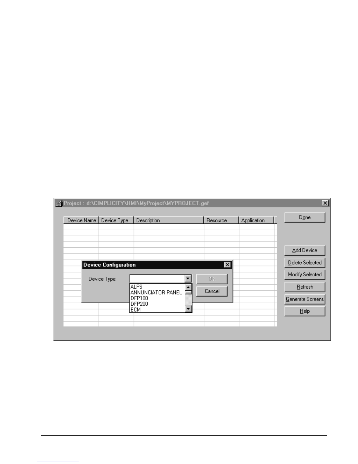
Select the Add Device button to begin adding device points to this project. The
Device Configuration dialog appears, prompting you to select a device type to add:
PMCS Interface Toolkit Configuring and Using PMCS Wizards • 9
Select the device type to add, and the Device Configuration dialog dynamically
expands to display the device-specific configuration parameters. For example, while
most devices require only five parameters (Type, Name, Description, Resource, and
the Server's Application name), some more complex device types require additional
parameters, such as selecting which Tabs will appear on the Tabular wizard screen at
runtime.
Most PMCS Advanced Wizards share a similar configuration dialog, as shown in the
first example below. However, as mentioned above, some more complex device
types such as the Universal Relay, Multilin 369, and EPM 7700, require some
addit ional confi g uration in formation, and these examples are sh own s ep arately.
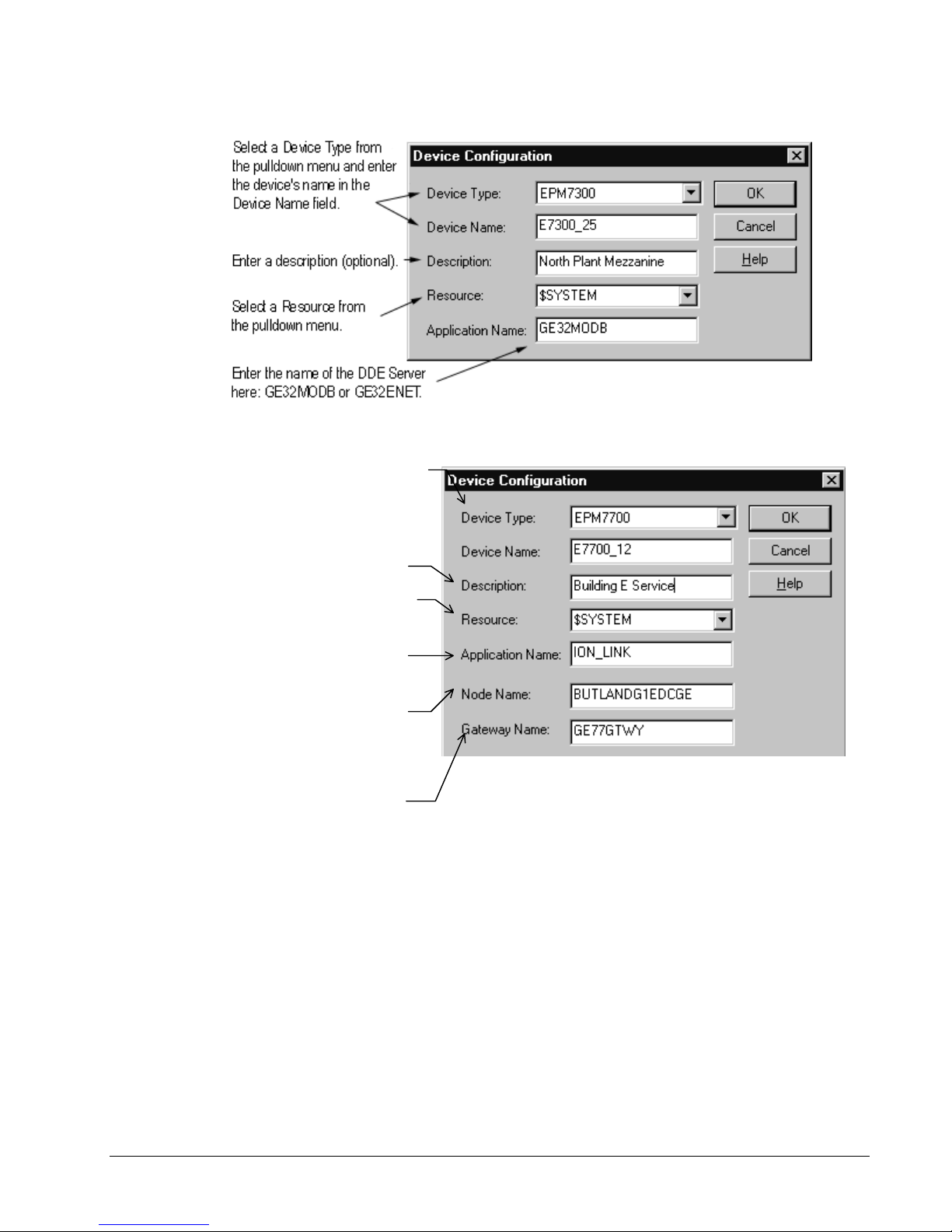
field with ION_LINK.
Select a Device Type from the
pulldown menu and enter the device's
name in the Device Name field.
Enter a description (optional).
Select a Resource from the pulldown
menu.
Complete the Application Name
Complete the Node Name field
with the name of the computer
running the Comm Server
connected to this particular device.
Complete the Gateway Name field
with GE77GTWY. See the
following note for details.
Devi ce Conf iguration Di alog - mo st PMCS Advanced Wi zards
Device Configuration Dialog - EPM 7700
10 • Configuring and Using PMCS Wizards PMCS Interface Toolkit
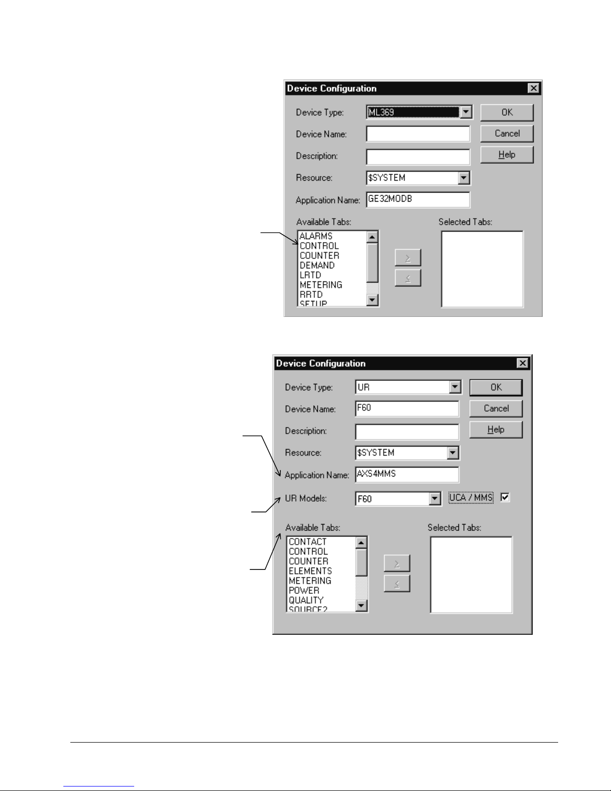
Choose the desired tabs to
display on the Wizard, and use
the right and left arrow buttons to
move the desired tabs from the
Available Tabs box to the
Selected Tabs box.
Complete the Application Name
field; typically GE32MODB, but
if UCA/MMS is selected, enter
AXS4MMS or name of MMS
Server.
Select the Model of UR which you
are configuring. This determines
the contents of the Available Tabs
list.
Devi ce Conf igurat ion Di alog - 369
Use the right and left arrow
buttons to move the highlighted
tabs between the Available and
Selected Tabs fields.
PMCS Interface Toolkit Configuring and Using PMCS Wizards • 11
Devi ce Conf iguration Di alog - Uni versal Relay d evices
When you have completed the Device Configuration dialog for the selected device,
click OK to add the device to the list displayed in the PMCS Power Builder window.
In th e exa mp le below, an F6 0 mod el UR, an ML 369, and five Mi croVersaTrip
devices have been added.
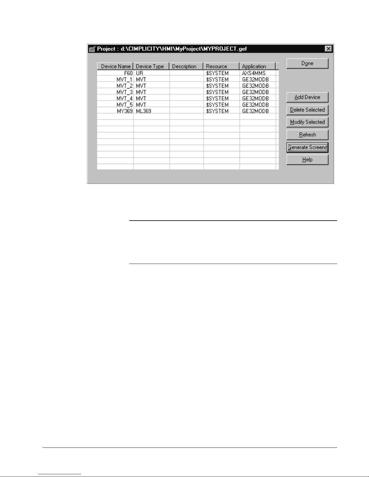
When you are done adding devices, you can generate the scr een s for all devices i n
one step by choosing th e Generate Scr eens but t on. Th e PMCS Power Buil der tool
creates one tabular screen per device type and one small faceplate per individual
device, following the many-to-one ar ch itectur e of the PMCS Advanced Wizards .
Note: While PMCS Power Buil der can gen erat e scr eens for m ost of the PMCS
Advan ced wi zards, th er e are some exceptions. Th e Annunciator Panel and the
EPM7700 screens are not automatically drawn by PMCS Power Builder, but instead
must be created manually after the points are created by PMCS Power Builder.
Follow the manual configuration instructions provided elsewhere in this guide to
configure the Annunciator Panel and EPM7700 points.
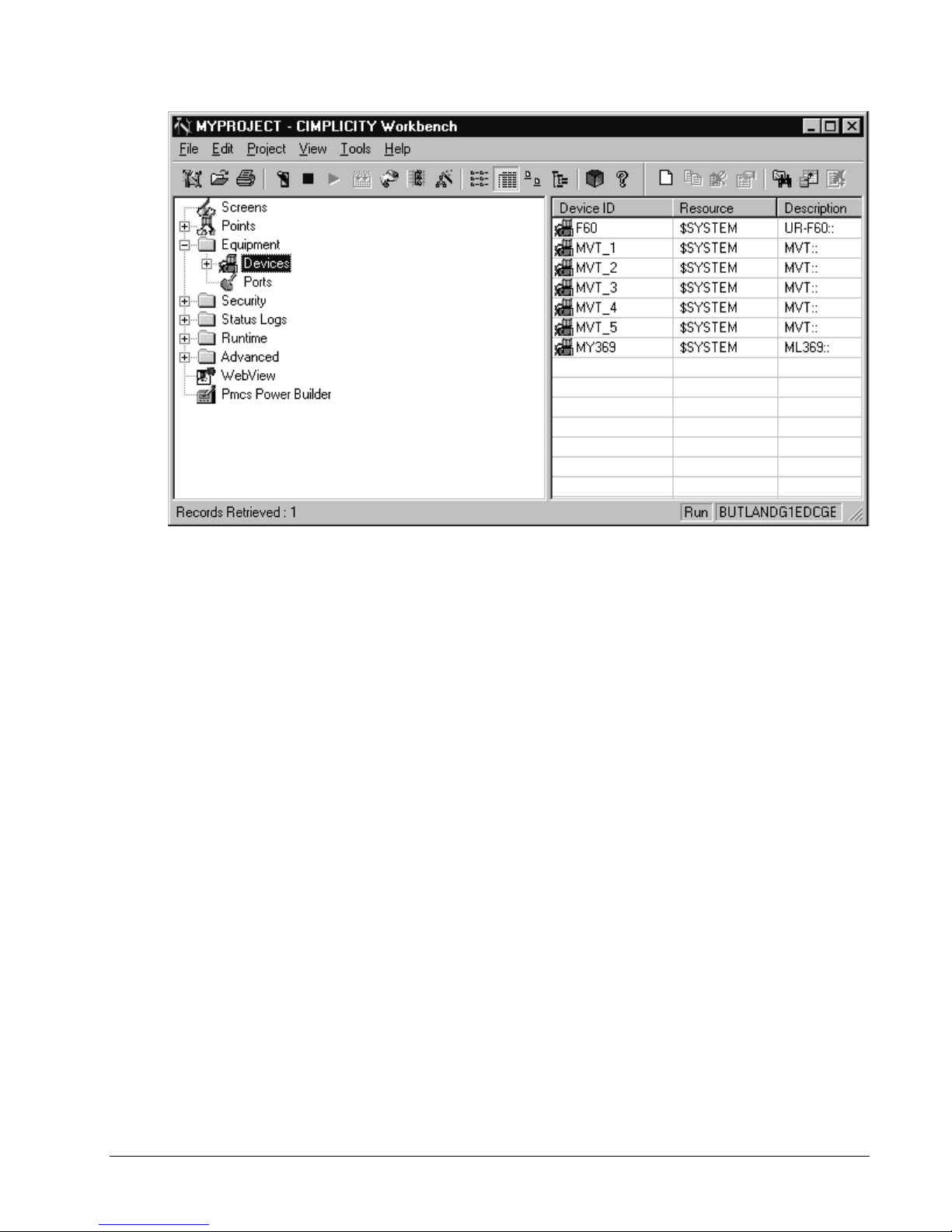
When Power Bu ilder ha s finished gen er ating scr eens for the configured d evi ces , click
the Done button to finish. PowerBuilder has automatically updated the project
configu ration and started the project for you. You can now browse the d evices,
poin ts, and screens created for you by PowerBui lder in th e Workbench. I f you don’t
see some i tems, hit the F5 key to refresh the Work bench displa y.
12 • Configuring and Using PMCS Wizards PMCS Interface Toolkit
For th e hi gh ly-flexibl e UR and 369 type devices, Pow er Build er creates a blank
"framework" wizard, with no pre-drawn tabs. In CimEdit the wizard will show no
tabs - the tabs will be dynamically redrawn based on the physical device being
accessed . For exam ple, if you use different models of th e Universal Rel ay in your
application, you might need to display a unique set of tabs for each type of relay.
With dynamic r e draw, you only need a single t abula r wizard in you r pr oje c t to show
any combination of tabs for any UR device. (The dynamic redraw feature can be
disa bl ed ; see Disabling Dynamic Redraw (369 and UR Tabular Wizards) for details.)
PMCS Interface Toolkit Configuring and Using PMCS Wizards • 13

Device Configuration -
Special Considerations for EPM 7700 only
The EPM 7700 Device Configuration dialog box contains two extra fields, which
must be completed during configuration. The Node Name field r equires that you
enter the name of the computer running the Communicati ons Server tha t con nects to
this particular device. Depending on the configuration of the EPM 7700 network,
this can be ei ther the Primary node comp uter, or a computer setu p a s a "Fu ll Station "
Secondary node. Refer to DEH-40035, the GE 7700 Gateway Users Guide, and
GEH-6514, PM CS Read This Book First, for m ore inf ormation on network
configuration. The Node Name field is required because the EPM 7700 does not use
the sam e DD E server as the rest of the standard PMC S devi ces , and the wi zard must
be directed to the location of the correct Communications Server for proper
configuration of DDE topic names.
Also, the Application Name field must be completed as ION_LINK rather than
GE32MODB or GE32ENET for the EPM 7700 device. The ION LINK program is
installed during initial PMCS setup if the EPM 7700 software option is selected.
When configuring Wizards on Secondary nodes, the Application Name field entry
does not fol low the PM C S wi zard convention of “\\Rem ot eC om p uter\I ON _ LI N K ” .
EPM 7700 Secondary nodes run a local copy of the ION LINK server, thus the
application name for EPM 7700 Large Faceplate wizards is always “ION_LINK”
whether the wizar d is install ed on the Primary node or a Secondary node. The Nod e
Name entry determines if the wizard is on a Secondary node.
The Gateway Name field must be completed with GE77GTWY, the application
name of the GE 7700 Gateway Server program. When configuring the EPM 7700
Tabular wizard on a Secondary node, the Gateway Name does follow the PMCS
wizard convention of “\\RemoteComputer\GE77GTWY” in the Gateway Name field,
where ‘ Rem oteComput er’ is the name of the PC wher e the GE 7700 Gateway
application is running – the Primary Node. The previous figure shows a Tabular Data
Dialog box as it would appear when configuring a Tabular Data wizard on a
Second ary node. The Node Name field contain s th e na me of the Primary Node
computer, the Application Name field is ION_LINK (as it is for ALL EPM 7700
wizards on ANY node) and the Gateway Name field points to the GE 7700 Gateway
Server running on the Primary Node PC.
14 • Configuring and Using PMCS Wizards PMCS Interface Toolkit
Refer to DEH-40035 for information on the Communications Server and 7700
Gateway Server.
Manually Configuring Wizards without using PMCS
Power Builder
This section explains the procedures for manually creating a device graphic wizard.
With on e ex cep tion (the EPM 7700 device type), the Advanced wi zards all share the
same configuration procedures.
NOTE: If you are configuring an EPM 7700 wizard, skip this section and go to
Manually Configuring the EPM 7700 on page 17, which details this wizard’s special
requirements.
To config u re the device g r aphics for a PMCS Advanced Wizard:
1. Open a new CimEdit screen.
2. Select a P MCS Advanced Wizard usin g th e O bject Explor er and drop it into the
ne w win dow.
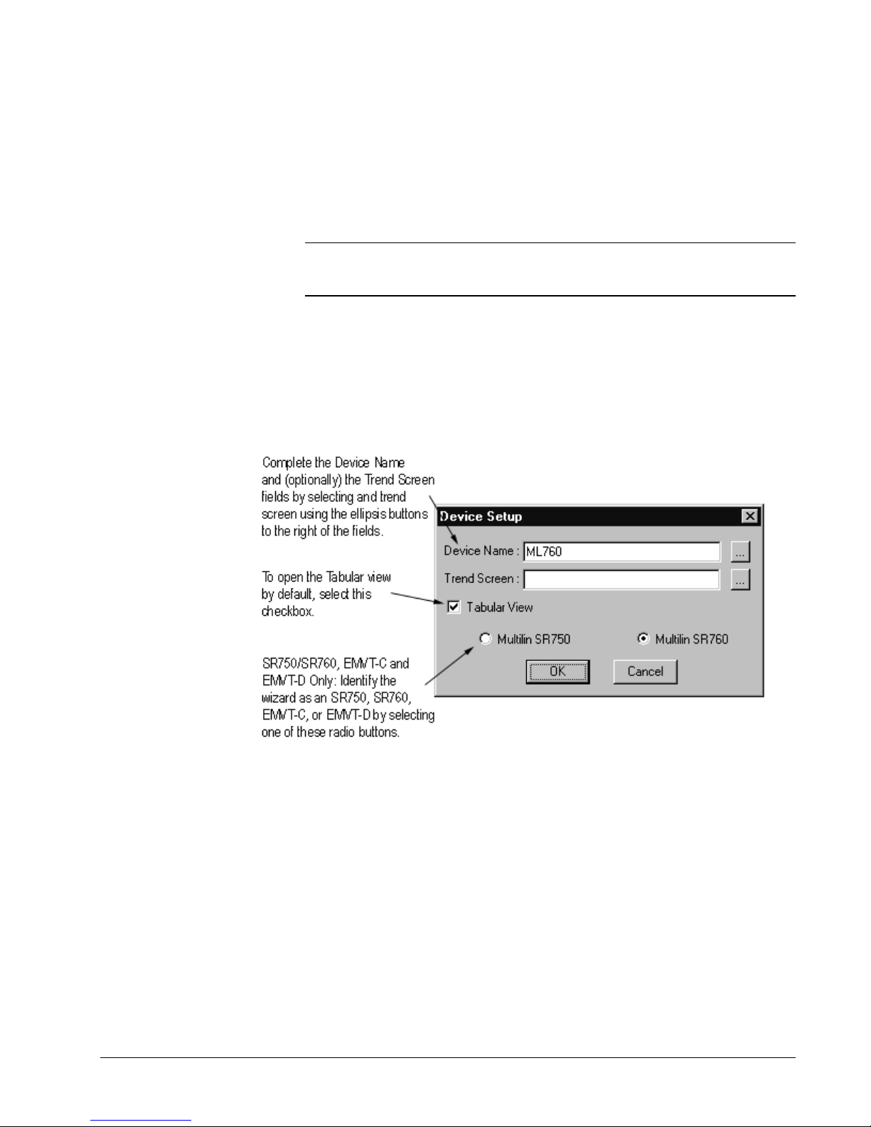
3. Dropping a wizard in the CimEdit screen causes the Device Setup dialog box to
appear, as shown below.
PMCS Interface Toolkit Configuring and Using PMCS Wizards • 15
4. Choose a default view for the wizard by selecting or deselecting the Tabular
View checkbox. If the Tabular View checkbox is s elected, the Tabular wi zard
will be displayed whenever this window is opened. If the Tabular View
checkbox is not selected, the Large Faceplate wizard is displayed by default.
5. To complete the Device N a me and Trend S cr een fields , click the ell ipsis butt on
to the right of each of these fields. This button displays a list of the devices
available in the project. (If no devices are available, stop and restart the project,
then continue; the devices should appear.) The Select Device dialog box is
shown in the following figure.
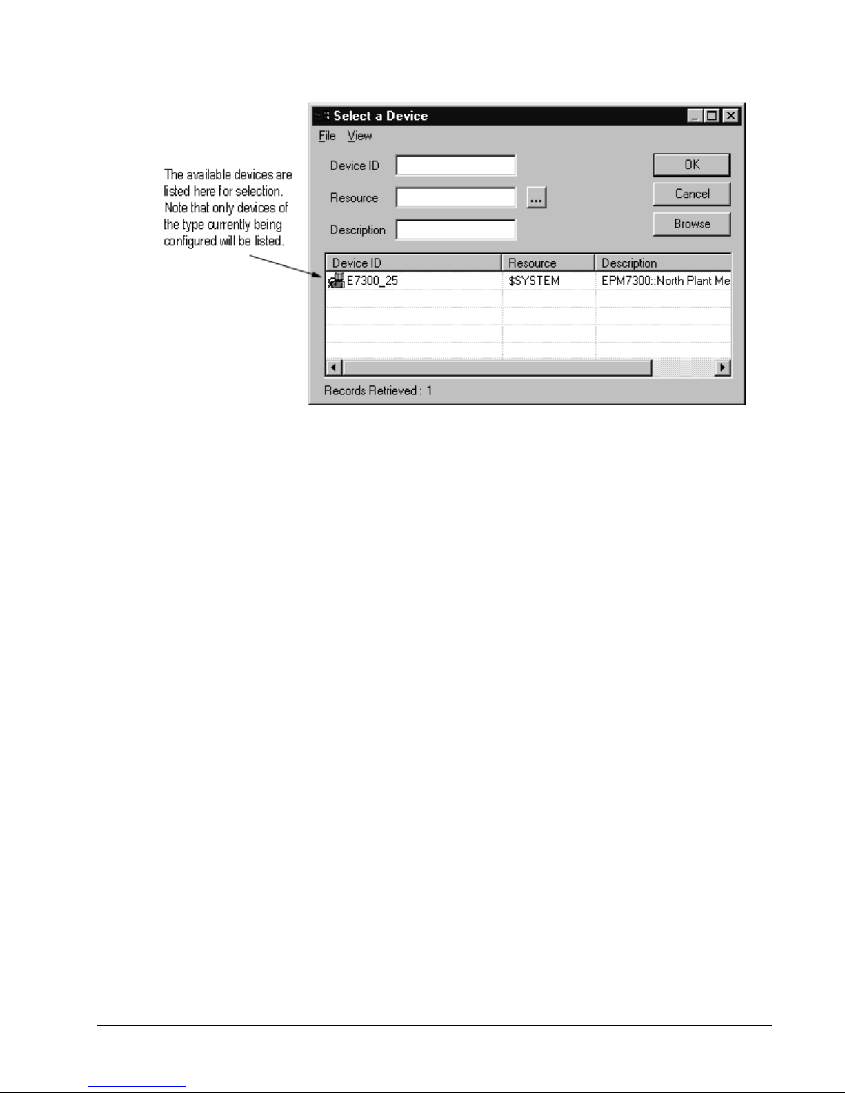
6. Select the appropriate device from the list and click OK.
7. After the wizard i s configured, save the win dow and close it.
8. Once you have configured an Advanced large faceplate/tabular graphic wizard,
you have t wo options. You can contin ue creatin g new wiz ard screens for each
physical device in the system, or you can use a single device wizard to view the
data of any physical device of that type using the new functionality provided by
the Advanced small faceplate wizards. See the Sample Application sec tion for
more information.
16 • Configuring and Using PMCS Wizards PMCS Interface Toolkit

Manually Configuring the EPM 7700 Wizard
The EPM 7700 device type is more complex than the other PMCS Advanced
Wizards, and its wizard reflects this. Dropping the EPM 7700 wizard into a project
creates eight separate screens, each linked to the others. Another unique property of
the EPM 7700 wizard is that the wizard itself is disposable. It is used only for the
initial configuration, and should be deleted after configuration is completed. The
eight s cr eens created by the wizar d ar e left for run- time use. The procedure for
configuring an EPM 7700 wizard is explained below.
Important: Follow the procedure to configure an EPM 7700 carefully - the wizard's
configuration should not be altered after it has been dropped. Changing the wizard
once it has been dropped requires you to delete the screens and re-create the wizard
with the desired prop erties.
1. Open a new CimEdit screen, using the Screens>New command.
Tip: If you plan to implement a Trend Window, create it before configuring the
EPM 7700 wizard, so that it will be available when you configure the device
graphics portion of the wizard.
2. Select a n EPM 7700 wizard using th e O bject Explorer an d dr op it into the new
window. You may see a warning message about not being able to undo this
action - disregard th is message .
3. Dropping a wizard in the CimEdit screen causes the Wizard Setup dialog box to
appear, as shown below. Note that there is no Tabular View checkbox; because
each of the Tabular s creens is cr eated independently of one another and the
Large Faceplate screen is also an independent screen, you are free to navigate to
any desired view. The notion of a default view does not apply to the EPM 7700
wizard.
PMCS Interface Toolkit Configuring and Using PMCS Wizards • 17
4. To complete the Device N a me and Trend S cr een fields , click the ell ipsis butt on
to the right of each of these fields, which displays a list of the devices available
in the project. (If n o devices are availabl e, stop and restart the pr oject , then
continue; the devices should appear.) The Select Device dialog box is shown
below.
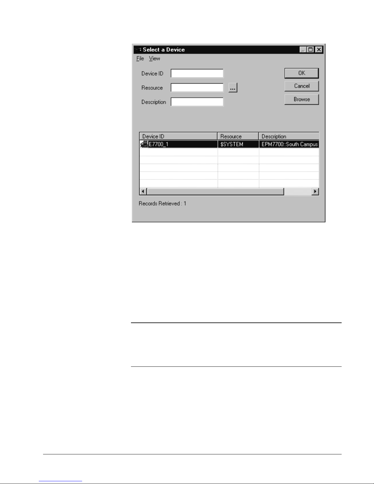
5. Select t he appropriate EPM 770 0 devi ce from the list and cli ck OK.
6. Select a Trend Window using the trend window list available by clicking the
ellipsis to the right of the trend window text box.
7. When the wizard has completed its configuration, close the current window and
DO NOT save it – it is not a functional part of the wizard, and it cannot be used
to create graphics for additional devices. All of the functional wizard screens
were created and sa ved during the configuration process.
8. Stop an d r estart the project, th en hi t F 5 to r efresh the list of screens in the
project .
Repeat steps 1 – 8 to create additional EPM 7700 device screens as necessary for
your application.
Note: Refer to the Sample Application section when de s igning your project to
understand and take advantage of PMCS Advanced Wizard functions such as the
many-to-one relationships possible with Advanced Small Faceplate Wizards and
Large Faceplate/Tabular Wizards. The configuration techniques available may save
considerable development time and effort, especially with regard to the EPM 7700
device type.
The fig ure below shows the one of the eight Tabul ar screens r es u lting from the
correct configuration of the EPM 7700 wizard. You can verify that there are in fact
eight separate screens rather than multiple pages of a single screen by selecting
different tabs at the bottom of the tabular wizard. Observe the file name at the top of
the window - the file name will change to match the selected tab.
18 • Configuring and Using PMCS Wizards PMCS Interface Toolkit
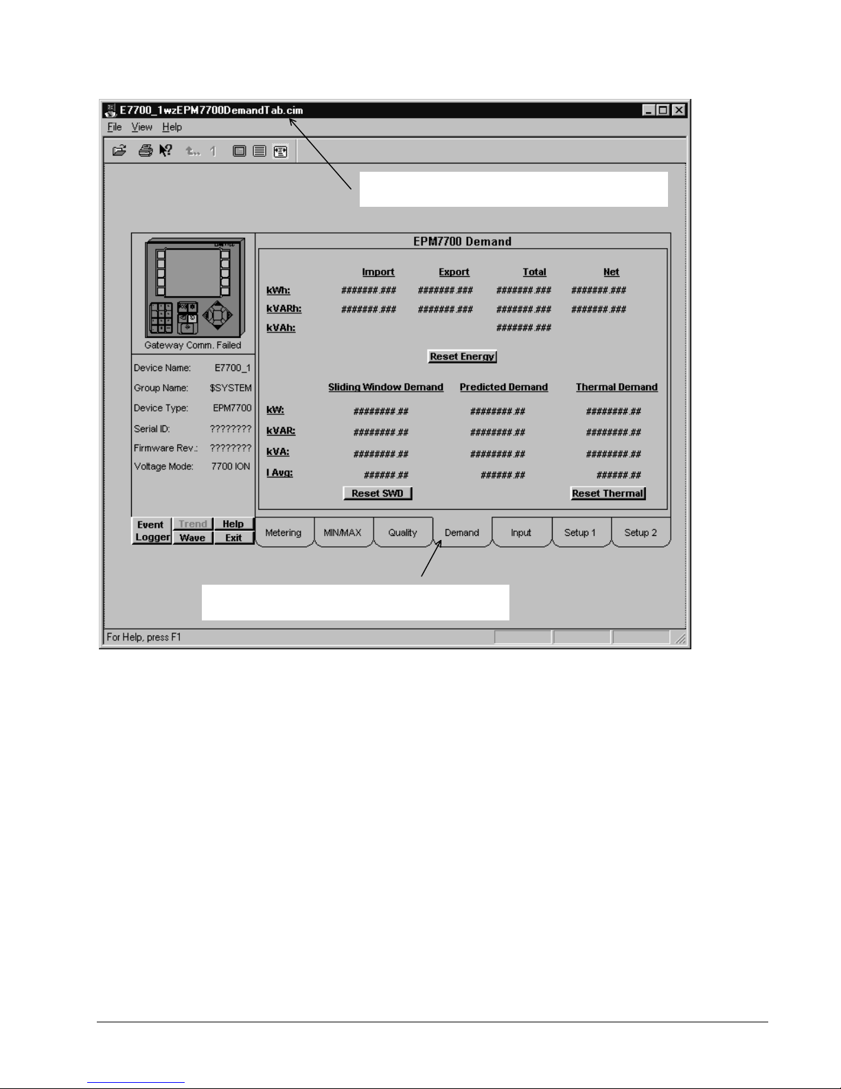
Selecting tabs here changes th e screen disp layed - note the file
Note the file name here - changes depending on the tab selected,
showing that each tab represents a separate screen file.
name at the top of the window changing to match the tab selected.
PMCS Interface Toolkit Configuring and Using PMCS Wizards • 19
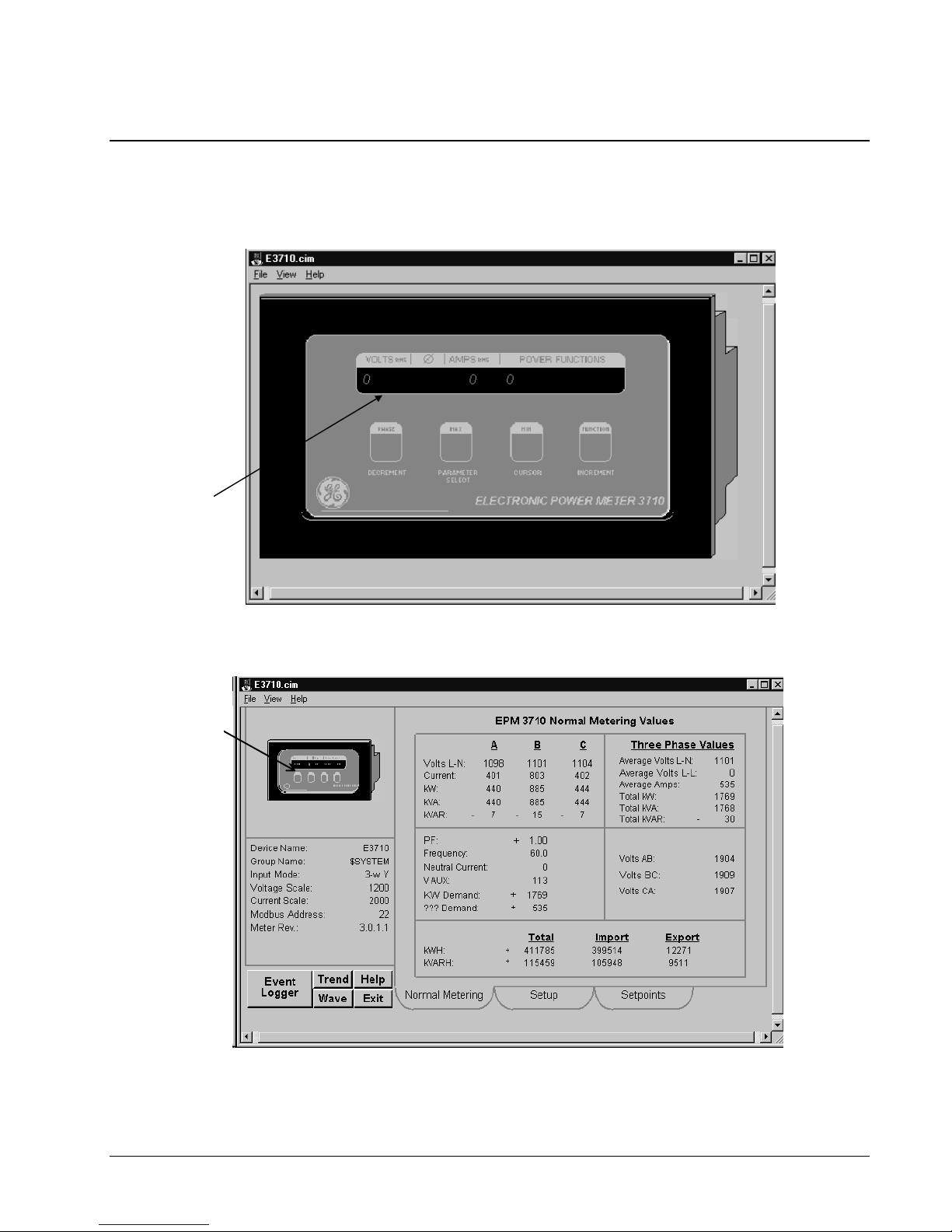
Using a PMCS Wizard
With th e wi zard confi g ured, you can t es t i t by launching the *.cim screen from
Windows Explorer or add it to a n exis t i ng proj e ct. Remembe r that the PM CS DDE
Server must be running before launching the wizard if it is to display real data.
Click the Large
Faceplate to open the
Tabular Data view.
Click the faceplate to
open th e Large
Faceplate view.
Click on the device’s display in the large faceplate wizard to open the Tabular data
screen wizard: Cl ick on the device icon in th e tabular wizard to return to the Large
Faceplate screen.
20 • Configuring and Using PMCS Wizards PMCS Interface Toolkit

Sample Application
The scenario described in this section illustrates the integration and time-saving
benefi ts of the PMC S Advanced Wizards.
The Small Faceplate wizards are often used to create visually accurate
representations of physical equipment line-up. Each Small Faceplate has a one-to-
one relationship with not only the physical device, but also the Large
Faceplate/Tabular wizard for that device. Clicking the Small Faceplate wizard for a
particular device opens a unique Large Faceplate/Tabular wizard associated with the
same physical device. We'll call this a one-to-one relationship of Small Faceplate to
Large Faceplate/Tabular.
PMCS Adva nced Wizard s may be used in th e standard, one-to-one m an ner.
However, they also support many-to-one configuration. In this scenario, several
Small Faceplate wizards of the same device type may all refer to a single Large
Faceplate/Tabular wizard. When the user clicks a particular Small Faceplate wizard,
the unique device identity information associated with that wizard is passed to the
Large Faceplate/Tabular wizard, which displays the data for the requested device.
Thus, with a single Large Faceplate/Tabular wizard, all the devices of a given type
may be viewed. The user navigates from the overview to the elevation view, then
selects a small faceplate wizard to open the tabular screen. However, instead of
configuring many separate tabular screens, only one is required. Obviously, this
saves considerable configuration time, as well as saving substantial system memory
during runtime. The one drawback of the many-to-one configuration is that since the
Small Faceplates all share access to the same Large Faceplate/Tabular wizard, only
one device's data may be displayed at a time. To display a Large Faceplate/Tabular
screen for multi ple PMCS Advanced Wizar d s at on ce, they must be configur ed in the
one-to-one manner, sacrificing the configuration time and system memory savings.
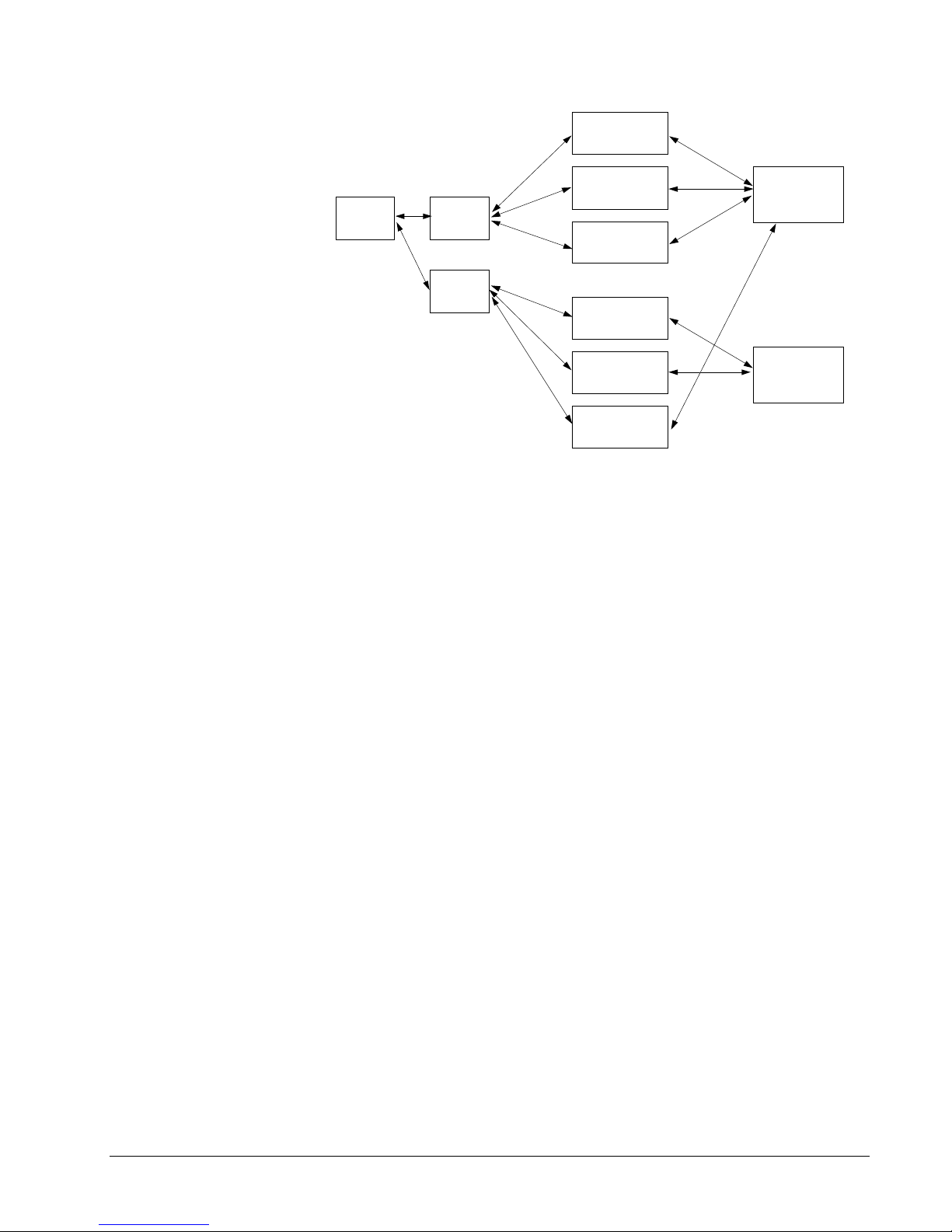
In the following example, the application has an Intro screen, from which the user
can access either of two panel boards of equipment. Panel Board #1 is equipped with
three EPM 7300 devices, while Panel Board #2 is equipped with two EPM 7700
devices and a single EPM 7300 device. Each device has an individual Small
Faceplate Wizard, which provides access to the Large Faceplate/Tabular wizard.
With th is architecture, only one Large Fa cep late/Tabu lar wizar d mu st be configured
for ea ch d evi ce type. Each of the Small Fa cep late wizards has access t o the
appropriate Large Faceplate/Tabular wizard, and when a Small Faceplate wizard is
invoked, it passes its identity information to the Large Faceplate/Tabular wizard,
which displays the data corresponding to the device associated with the invoked
Small Faceplate wizard.
PMCS Interface Toolkit Configuring and Using PMCS Wizards • 21
Intro
Screen
Panel
Boar
d #1
Panel
Boar
d #2
EPM 7300_1
Small Faceplate
EPM 7300_2
Small Faceplate
EPM 7300_3
Small Faceplate
EPM 7700_1
Small Faceplate
EPM 7700_2
Small Faceplate
EPM 7300_4
Small Faceplate
EPM 7300
Tabular/Large
Faceplate
EPM 7700
Me te ring
Screen
The details of configuring one-to-one or one-to-many are described in Small
Faceplate Configuration on page 24.
22 • Configuring and Using PMCS Wizards PMCS Interface Toolkit
Small Faceplate Wizards
Usage
The Small Faceplate wizards are icon-sized graphics typically used to create accurate
elevation views and one-line diagrams. These wizards are provided with logic to
open another window, typically either a Large Faceplate/Tabular Data Screen
wizard. There are several directories of Small Faceplate wizards to choose from.
PMCS Interface Toolkit Configuring and Using PMCS Wizards • 23
Small Faceplate Config uratio n
The Small Faceplate wizard for the PMCS Advanced Wizards offers additional
fun c tions beyond sim ply opening a designated wind ow. If you so c hoose , you may
configure a single Large Faceplate/Tabular wizard for each device type, regardless of
how many actual devices of that type are installed, and use multiple Small Faceplate
wizards to access data on each device. This feature operates by assigning an identity
to each Small Faceplate wizard, and passing this identity information to the Large
Faceplate/Tabular wizard when the Small Faceplate wizard is selected. The single
Large Faceplate/Tabular wizard opens, displaying the data for the selected device.
The many-to-one wizard configuration offers substantial configuration time savings
and mem ory saving s, esp ecially for the EPM 7700, where each Large
Faceplate/Tabular wizard actually consists of eight separate screens. A minor
drawback to this approach is that you may only display the Large Faceplate/Tabular
wizard for a single device at a time. To view data on a different Advanced Wizard
sharing this Larg e F aceplate/ Tabular screen, you must close th e Large
Faceplate/Tabular wizard and open it again through the desired device's Small
Faceplate wizard.
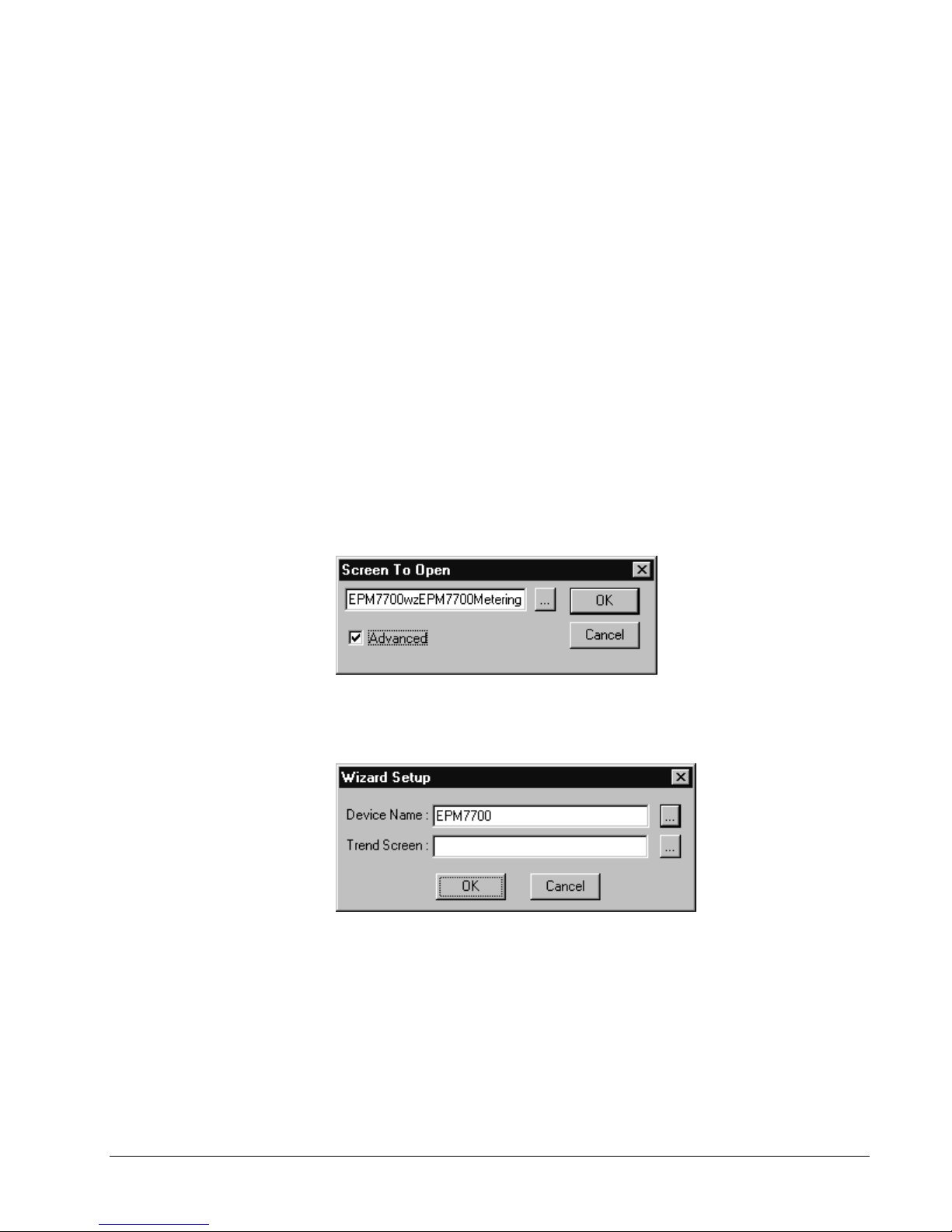
If you ch oos e to use this man y-t o-one technique, select the Advanced check box i n
the Wizard Configuration dialog, as shown in the following figure. If the Advanced
checkbox is not selected, the Small Faceplate wizard functions like any other Small
Faceplate wizard, simply opening the selected screen.
Selecting the OK button in the Screen To Open dialog box, with a device screen
selected and the Adva nced checkb ox s elected, d isplays th e Wizard Setu p dialog box
(shown below), prompting you to choose the identity of the device you wish to
associate with this Small Faceplate Wizard.
24 • Configuring and Using PMCS Wizards PMCS Interface Toolkit
 Loading...