

GE PNRQ21RRB00, PNRQ21RBN00 Owner’s Manual

Safety Instructions
Safety Instructions .............. 9
Specification Guidelines ......... 3
Operating Instructions
About the RO System ......... 4, 5
Installation Instructions
Tools and Materials Required ..... 6
Before Beginning Installation ...6, 7
Mounting System Installation ..... 8
Feed Water Supply ........... 9-19
Faucet Assembly ............ 13, 14
Batter T Installation ............ 14
Filtration Drain Connection . .15, 16
Storage Tank and Startup ....... 17
ge.com
PNRQ21LBN
PNRQ21Lt_
Osmose Invers e
Syst&mede Filtration
La section fran_aise commence a la page 27
>
Care and Cleaning
Prefilte_, Postfiher and
RO Cartridge Replacement ...... 18
Sanitization .................. 19
Water Test Kit ................ 90
Troubleshooting Tips .2 -2.
...... _1 _3
Consumer Support
Consumer Support ..... Back Cover
Parts i,ist/Catalog .......... 94, 95
Warranty .................... 26
Tested andCertified by NSFInternational to
NSF/ANSI Standard 58. For the reduction of the
claims specified, see the Performance Data Sheet.
Essay_et certifi_ par NSFInternational
conform_ment aux normes 58NSF/ANSI. Pour
la r_duction descaract_ristiques indiqu_es,
consultez la feuille de donn_es de rendement.
Probado y certificado por NSF International por
cumplir con el est_ndar 58.Parala reducci6n de
reclamos especificados, ver la hoja de datos de
desempefio.
Osmosis Inversa
Sistema de Filtraci6n
La seccion en espa_ol empieza en la pagina 55
Write the model and serial
numbers here:
Model #
Serial #
You can find them on the bracket.
215Cl174P007 49-50214101710 05-06JR
iMPORTANTSAFETYiNFORMATiON.
READALL INSTRUCTIONSBEFOREUSING.
n W WI-III IIWIIW LI -
SAFETYPRECAUTIONS
• Check with your state and local public works
depamnent for plumbing and sanitation codes.
You must ff}llow these guidelines _s you install the
Revexse Osmosis system. Using a qualified instal/or
is recommended.
• If house water pressure is over the rnaxiI-ntm]
(120 pounds per square inch), install a pressure
reducing valve in tile water supply line to tile
Reverse Osmosis system.
• Be sure the water suppl)' confbmls with the
SpecificationGuidelines.If tile water suppl)' conditions
axe unknown, contact your municipal water company
or your local health department for a list of
contaminan ts ill your area and a list of laboratories
certified by your state to analyze drinking x_ater
WARNIN&Bef .eusingtileRe,'e,seOsmosis
system for tile first time, tile system must be
purged. The Reverse Osmosis camidge contains
a food grade preservative that m ust be purged
flom the system. The presets,alive will give product
water an unpleasant taste and odor
WARNING:Do.or usewithwateithatis
nlicrobiologica/ly unsafe or of unknown quality
• property damage or persona/injury.
without adequate disinfection before or after file
systenl. Sysmms cerdfied for O,st reduction may
be used on disinfected water that nlay contain
filmrable cysts.
This system ll_k',;been tested for file treamlent of
water cont_dning pentavalent aisenic (a/so hlown
_ksAs(V), As(+5) or aIsenate) at concenm_tions
of 0.050 mg/L or less. This system reduces
penmva/ent aisenic, N_t mW not renlove oilier
fbrnls of msenic. This sysmm is to be used on wamr
supplies containing a demctable fiee chlonne
residuN or on wamr supplies that have been
dem(mstrated to contain only penmva/ent msenic.
Treatment with chloramine (.combined chlonne)
is not sufi_icientto ensure conlplete conversion of
t]iva/ent aisenic to penmva/ent arsenic. Please see
the Arsenic Facts section of the Perfbmlance Data
Sheet for fi_rther infbrInation.
This reverse osmosis system contains a replaceable
component cddca/to effidency of tile sysmm.
Replacement of tile reverse osnlosis component
should be with one of identical spedfications, as
defined by the nlanufilcmre_; to _L%tne tile stone
effidency and contaminant reduction perfbmlance.
This Reverse Osmosis system must be properly installed and located in accordance with the
Installation Instructions before it is used.
PROPERINSTALLATIONANDMAINTENANCE
• Install or store where it will not be exposed to InstaUing a second tank will improve this
temperatures below fieezing or exposed to any _pe perfomlance. An RVKIT call be used.
of weatheL _tei fleezing in tlle system will • If Rex'else Osmosis system is connected to a
damage it. Do not attempt to treat water over 100°E refligerator icemake[; aspecial icemaker
• Do not install on NOT WATER.Tile temperature connection kit is required (RVKIT). Do not use
of tile water supply to tile Rex'else Osmosis system copper tubing for tile connection between tile
illtlSt be between tile nlininmnl of 40°F and tile _ Reverse Osnlosis syste[I1 and tile refligelv_toi.
illaxililtni1 of 100°E See tile
• Extended non-use ofthe Reverse Osmosis system, material mCterinstallation. Small parts remaining Jter
If die system has not been used for one week or
more, open tile RO wamr faucet and allow the
system to drahl. Close tile RO water faucet and
allow tile sysmnl m regenerate tile wamr supply:
• Recommended instaUation is under tile sink.
Howevei; tile unit call be instaUed in a relnom
location, up m 20 feet away flom tile sink.
• HoweveI; additional mamrials will be required,
including additional robing and exmnsion
phone cable. This exmnoon phone cable
Illtlst be 6 conductor wire and connecmls;
l),pi(_d4 conductor wire will not work. See parts
list m obtain additional mamfials flom GE.
• I,ocating the rank on a b_ksement tool; with the
faucet at a filSt floor sink may result ill some loss
of flow rate and capad b, (approxinlately 20%).
Specification
Guidelines.
IL WARNING:Discard all unttsed pmts mid packaging
file instaUation could be a dloke haaud.
• Sanitize upon installation of the Rex'else Osmosis
system and _ffterselwicing inner parts, in dudin g
replacement of prefiltei; posdilter and Reverse
Osmosis cartridge. It is important to have clean
hands while handling inner parts of the system.
See tile SanitizingtheReverseOsmosisSystemsection.
• This Reverse Osmosis system contains a replaceable
treatment component critical for eff)ctive
reduction of total dissoked solids. This product
water shall be tested periodically to veal6' that the
system is performing satisfactorily See tile About
the Water Test Kitsection.
BESURETOFOLLOWALLAPPLICABLESTATE
ANDLOCALCODES.
READAND FOLLOWTHISSAFETYINFORMATIONCAREFULLY.
SAVETHESEINSTRUCTIONS
2
Specificationguidelines, gecom
Product- height11" width 10.5" depth4"
The system makes a good supply of ddnking water each day.
How muchit will makedependsprimarilyonthesethings...
Feedwater pressurelimits--pounds persquareinch (psi) ...................... 40-1208
Feedwater temperaturelimits_inimum/maximum degreesF ................. 40-100
MaximumTotalDissolvedSolids(TDS)--partspermillion(ppm)................ 2000
Maximumwaterhardness@6.9pH recommendedtooptimizemembrane
life--grains pergallon(gpg)................................................. 10
8
7.5
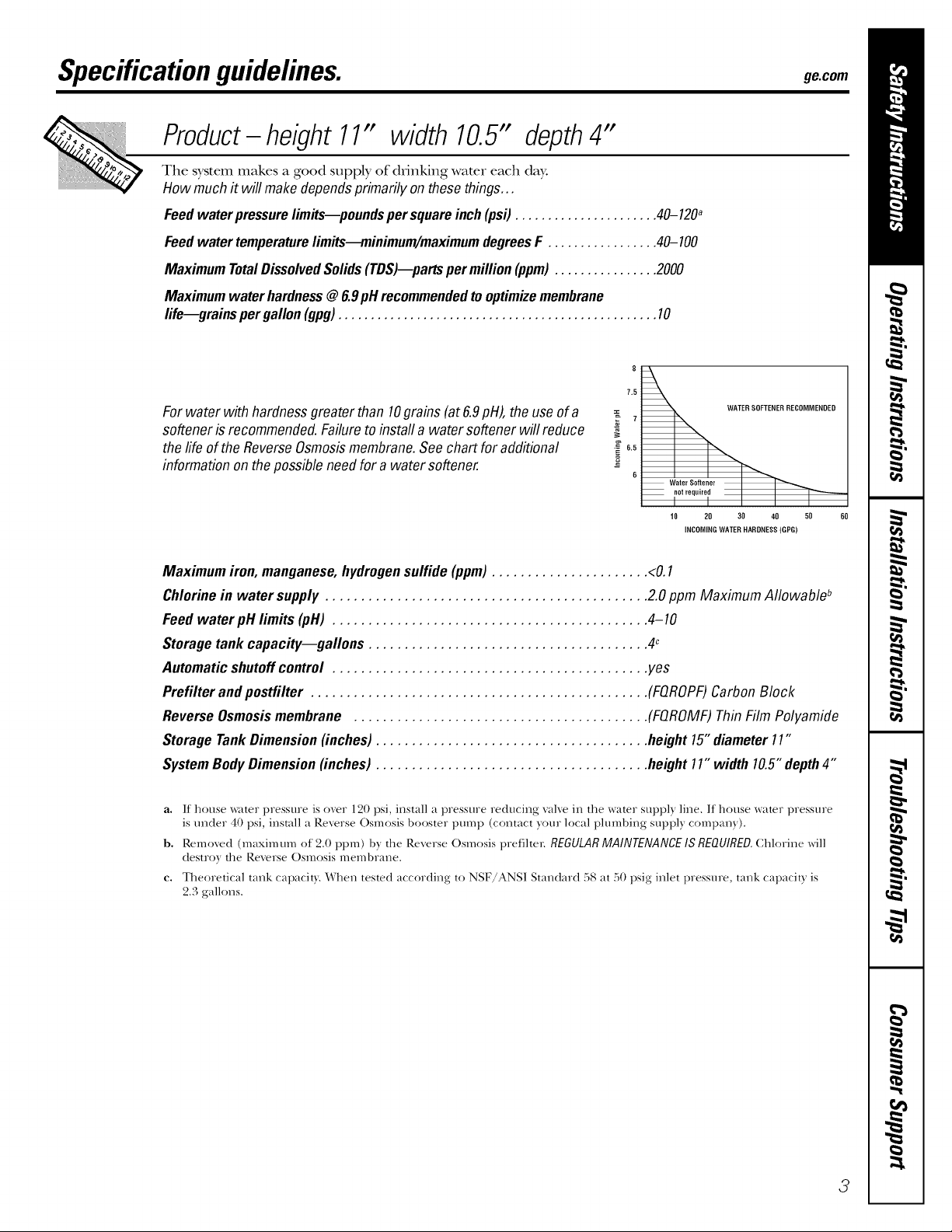
Forwater with hardnessgreaterthan 10grains(at 6.9pH),the useofa
softenerisrecommended.Failuretoinstafla watersoftener willreduce
the lifeof theReverseOsmosismembrane.See chartforadditional
informationon thepossible needfor a watersoftener.
==
6.5
6
Water Softener
WATER SOFTENER%_RECONNENRED
I I I I I
10 20 30 40 50 60
INCONNGWATER HARONESS(GPG)
Maximumiron,manganese,hydrogensulfide (ppm)...................... <0.1
Chlorinein water supply ............................................. 2.0ppm Maximum Allowableb
Feedwater pH limits (pH) ............................................ 4-10
Storage tank capac#y--gallons ....................................... 4c
Automaticshutoff control ............................................ yes
Prefilter andpostfilter ............................................... (FQROPF)Carbon Block
ReverseOsmosismembrane ......................................... (FQROMF)ThinFilm Polyamide
StorageTankDimension(inches)...................................... height15"diameter11"
SystemBodyDimension(inches) ...................................... height11"width10.5"depth4"
a. If house _lter pressure is over 120 psi, install a pressure reducing valve in the water stEppl) line. If house water pressure
is under 40 psi, install a Reverse Osmosis booster pmnp (contact)our local plumbing suppl) compan)).
b. Removed (maximum of 2.0 ppm) b) the Reverse Osmosis pref]ltel: REGULAR MAINTENANCE IS REQUIRED. Chlorine will
destro} the Reverse Osmosis membrane.
C,
Theoretical tank capacity. \,Xhen tested according to NSF/ANS] Standard 58 at 50 psig inlet pressm_e, tank capacity is
2.3 gallons.
3
Aboutthe reverseosmosissystem.
How the Reverse Osmosis System Works
Reverse Osmosis reduces Total DissoNed Solids (TDS) and organic matter fiom wamr by diffi_sing it through a special
membrane. The membrane sepmates minerals and impmities fiom the water and they are flushed to the drain. For the
reduction of the claims specified, see Perfbmmnce Dam Sheet. High qualitT product water goes directly to the drinking
water faucet or to the storage rank. The sysmm makes a good supply of drinking wamr each day. How much it makes
depends on the feed wamr supply pressure, temperature and quality.
The prefilter and posffilter are replaceable cartridges. The carbon prefilter reduces chlorine while also filtering sediments.
The posffilter reduces any other undesirable tastes and odors before you use the _ater
These systems include an elecnonic fimcet assembly with a prefilter and poslfilter change remindel; Rexerse Osmosis
membrane change reminder and a stares okay reminder
The prefilter and poslfilter change reminder will flash amber aRer six months haxe passed or 900 gallons haxe been used.
When this occurs, it is time to replace these cartridges and sanitize the system.
The membrane change reminder flashes amber xd-len the TDS monitor in the system has measured the amount of impurities
remoxed is lessthan 75%. When this occm_, it is time to replace this Rexerse Osmosis membrane cartridge and sanitize the system.
Finally, a green flashing ligt_t _ill indicate the system is flmctioning properly.
Description of theReverse Osmosis System
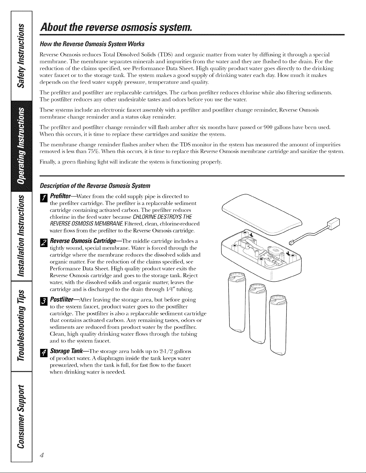
_Prefi/ter_Water from the cold supply pipe is directed to
the prefilter cartridge. The prefilter is a replaceahle sediment
cartridge containing activated carbon. The prefilter reduces
chlorine in the feed water because CHLORINEDESTROYSTHE
REVERSEOSMOSISMEMBRANE.Filtered, cleau,chlorine-reduced
water flowsfi'om the prefilter to the ReverseOsmosiscartridge.
_'_Reverse OsmosisCartridge--_he middle cartridge includes a
tightb,' wound, special membrane. Water is forced through the
cartridge _d_ere the membrane reduces the dissolved solids m_d
orgmfic matten For the reduction of the claims specified, see
Performance Dam Sheet. High quality product water exits the
Reverse Osmosis cartridge and goes m the storage tank. Reject
wam_;,dth the dissoked solids and organic matte_; leaves the
cartridge and is discharged to the drain through 1/4" robing.
_]Postfilter--Atker leaving the storage area, but before going
to the system faucet, product water goes to the postfilter
cartridge. The postfilmr is also a replaceable sediment carnidge
that contains activated carbon. Any remaining tasms, odors or
sediments are reduced fiom product wamr by the postfilmL
Clean, high qualitT drinking wamr flows through the robing
and m the sysmm faucet.
ErJStorage Tank--The storage area holds up to 2-1l/2 gallons
of product wateL A diaphragm1 inside file tank keeps water
pressurized, when the rank is fifll,for fast flow m file fimcet
when drinking water is needed.
4
_e.com
_'_ghock Va/vO--The check valve ptevents a backward flow of product water fiom the storage tank. A backward flow could
cause the Reverse Osmosis meInblane to rupture.
_]Automatic ShutoffAssembly--To conserve water, the drinking water s_stem has an automatic shutoff When the storage rank
has filled to capaci_ and the drinking water f:,mcetis closed, presstHe closes the shutoff Water flow to the ReveFseOsmosis
housing is shut offuntil drinking water is used again, and p_essme drops in the Reverse Osmosis s_stem.
F_F/ow Control--The flow cont_ol regulates the flow of water th_ough the Revezse Osmosis cartti(tge at the requiled rate to
p,oduce high quality water The control is located in the 1/4" drain line exiting off the manifold.
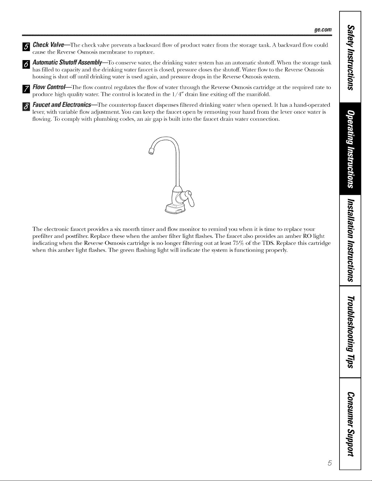
FaucetandE/ectronics--Whecountertop faucet dispenses filtered drinking water when opened. It h_ksa hand-operated
leve_;with variable flow adjustment. You can keep the faucet open b}_removing },,ourhand flom the level once water is
flowing. To comply with plumbing codes, an air gap is built into the faucet drain water connection.
The electronic faucet provides a six monfll timer and flow monitor m remind you when it is time to replace your
prefilmr and postlqlm_. Replace these when the amber filter light flashes. The faucet also provides an amber RO light
indicating when the Reverse Osmosis caruidge is no longer filmring out at least 75% of the TDS. Replace this cartridge
when this amber light flashes. The green flashing light will indicam the system is flmcfioning properly.
5
[Insta..ation[,everseOsmos,sF,,trat,onS,stem]
nstructl Ons ModelsPNRQ21LBNandPNRQ21LRB
I Questions? Call 800.GE.CARES (800.432.2737) I
-& WARNING: Read entire manual. Failure to follow all guides and rules could cause
personal injury or property damage.
• Check with your state and/or local public works department for plumbing codes. You must
follow their guides as you install the Water Filtration system.
NOTE: Failure to comply with these installation instructions will void the product warranty, and
the installer will be responsible for any service, repair or damages caused thereby.
TOOLS AND MATERIALS
REQUIRED FOR INSTALLATION
• Electric drill and 1-1/4" Drill Bit (type as
required) if mounting is needed for faucet
• Two (2) Adjustable Wrenches
• 1/16" Drill Bit (optional for pilot holes)
• Tape Measure
• Phillips and Flat Blade Screwdrivers
• Utility Knife
• If your main water line is a rigid pipe,
you will require a compression fitting
and possibly other plumbing hardware
to complete the installation.
A
-&CAUTION: To avoid damaging the
sink, consult a qualified plumber or installer
for drilling procedures. Special drill bits may
be needed for porcelain or stainless steel.
CONTENTS INCLUDED
WITH PRODUCT
BEFORE BEGINNING INSTALLATION
Read these instructions completely
and carefully.
• IMPORTANT - Savethese
instructions for local inspector's use.
• IMPORTANT - Observeall
governing codes and ordinances.
• Note to Installer- Be sure to leave these
instructions with the Consumer.
• Note to Consumer- Keep these
instructions for future reference.
• Proper installation is the responsibility
of the installer.
• Product failure due to improper installation
is not covered under the Warranty.
• A shutoff valve must be available or added
near the installation point.
• Reverse Osmosis Assembly and Tubing
• Product Literature (Owner's Manual and
Installation Instructions)
• Performance Data Sheet
• Feed Water Adapter and Supply Valve
• Faucet Assembly with Electronic Base
Monitor and Tubing
• Storage Tank
• Drain Line Adapter
6
Installation instructions
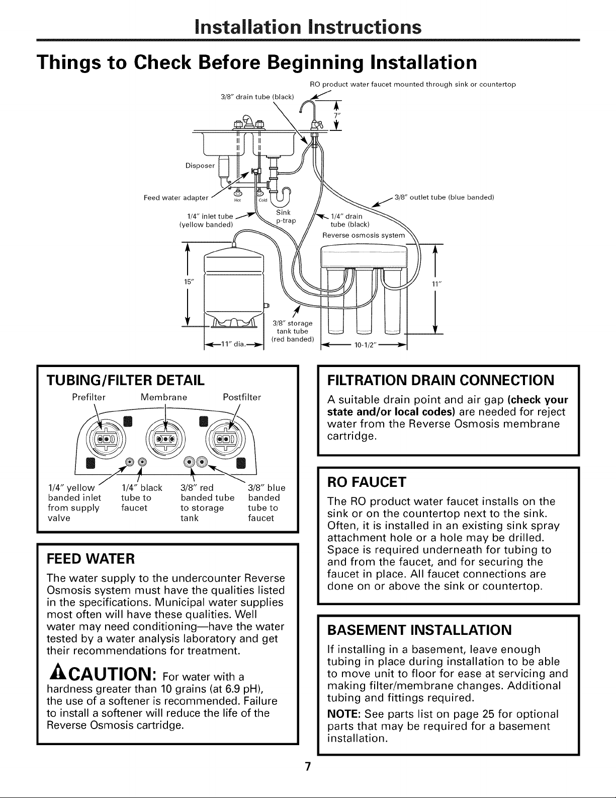
Things to Check Before Beginning Installation
RO product water faucet mounted through sink or countertop
3/8" drain tube (black)
Disposer
Feed water adapter
1/4" inlet tube
(yellow banded)
T
15"
!
TUBING/FILTER DETAIL
Prefilter Membrane Postfilter
®
1/4" yellow 1/4" black 3/8" red 3/8" blue
banded inlet tube to banded tube banded
from supply faucet to storage tube to
valve tank faucet
FEED WATER
The water supply to the undercounter Reverse
Osmosis system must have the qualities listed
in the specifications. Municipal water supplies
most often will have these qualities. Well
water may need conditioning--have the water
tested by a water analysis laboratory and get
their recommendations for treatment.
Ji11_/-&U/IUl_l: For water with a
hardness greater than 10 grains (at 6.9 pH),
the use of a softener is recommended. Failure
to install a softener will reduce the life of the
Reverse Osmosis cartridge.
3/8" storage
tank tube
(red banded)
j 3/8" outlet tube (blue banded)
10-1
FILTRATION DRAIN CONNECTION
A suitable drain point and air gap (check your
state and/or local codes) are needed for reject
water from the Reverse Osmosis membrane
cartridge.
RO FAUCET
The RO product water faucet installs on the
sink or on the countertop next to the sink.
Often, it is installed in an existing sink spray
attachment hole or a hole may be drilled.
Space is required underneath for tubing to
and from the faucet, and for securing the
faucet in place. All faucet connections are
done on or above the sink or countertop.
BASEMENT INSTALLATION
If installing in a basement, leave enough
tubing in place during installation to be able
to move unit to floor for ease at servicing and
making filter/membrane changes. Additional
tubing and fittings required.
NOTE: See parts list on page 25 for optional
parts that may be required for a basement
installation.
7
Installation instructions
REVERSE OSMOSIS ASSEMBLY
MOUNTING SYSTEM
INSTALLATION
Choose a location under the sink to mount
the system. Location should be easily
accessible, with adequate clearance between
the bottom of the filter cartridges and the
floor or bottom of the cabinet for removal
of filter cartridges. Allow enough space on
either side of the system for the tubing
connections.
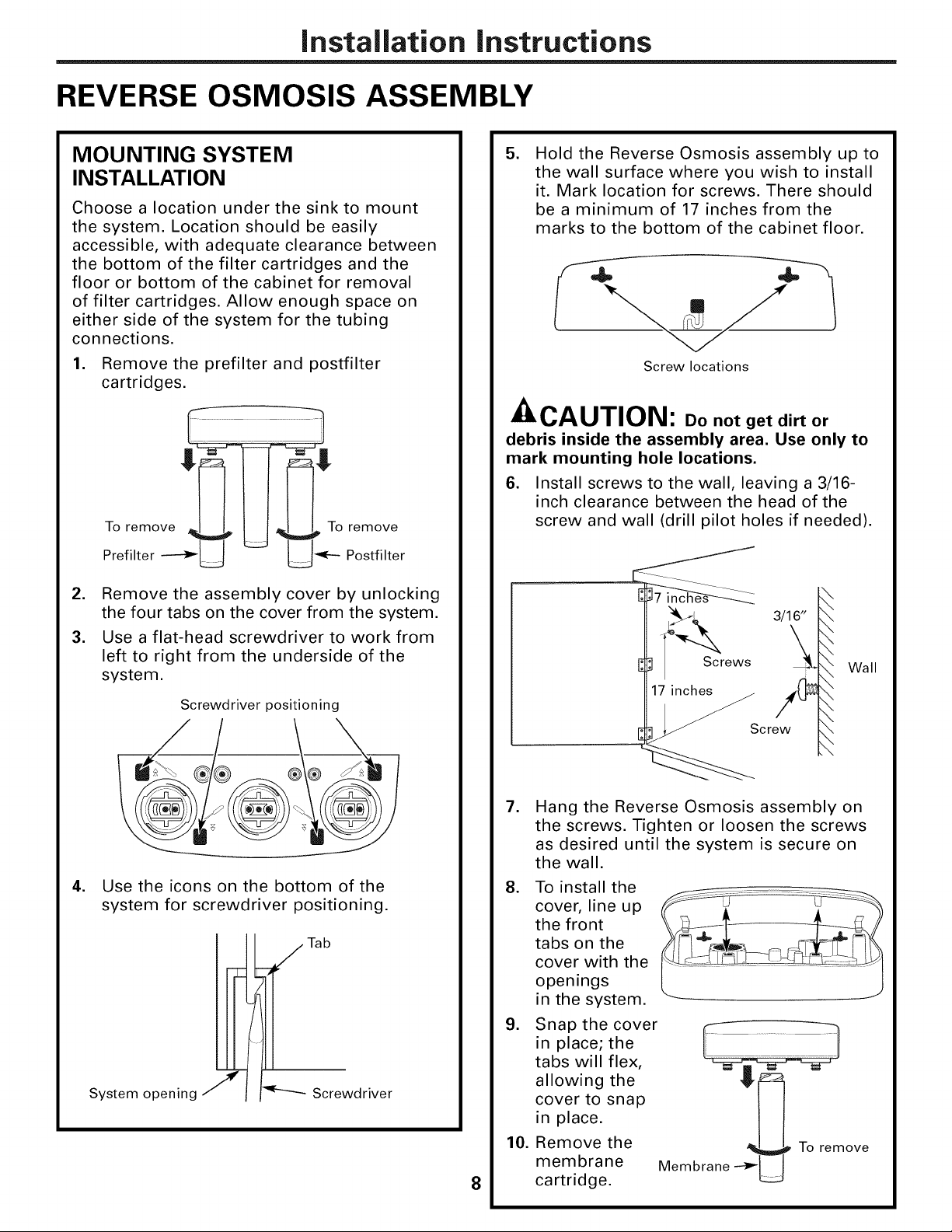
1. Remove the prefilter and postfilter
cartridges.
To remove To remove
Prefilter _ _ Postfilter
2. Remove the assembly cover by unlocking
the four tabs on the cover from the system.
3. Use a flat-head screwdriver to work from
left to right from the underside of the
system.
.
Hold the Reverse Osmosis assembly up to
the wall surface where you wish to install
it. Mark location for screws. There should
be a minimum of 17 inches from the
marks to the bottom of the cabinet floor.
Screw locations
A,,,^, ,-,-,,-,R,
JULIL,/-IUIIUI_I: Do not get dirt or
debris inside the assembly area. Use only to
mark mounting hole locations.
6. Install screws to the wall, leaving a 3/16-
inch clearance between the head of the
screw and wall (drill pilot holes if needed).
3/16'_
Screws
Wall
Screwdriver positioning
.
Use the icons on the bottom of the
system for screwdriver positioning.
//Tab
I
1
System opening J
Screwdriver
.
Hang the Reverse Osmosis assembly on
the screws. Tighten or loosen the screws
as desired until the system is secure on
the wall.
8. To install the
cover, line up
the front
tabs on the
cover with the
openings
in the system.
9. Snap the cover
in place; the
tabs will flex,
allowing the
cover to snap
in place.
10. Remove the
membrane
8
cartridge.
crew
Membrane __ To remove
Installation instructions
FEED WATER SUPPLY
Check and comply with local plumbing codes as you plan, then install a cold feed water supply fitting.
A. PREFERRED INSTALLATION
Utilizing existing kitchen sink water supply
valve (A) and removable faucet tubing (B).
1. Refer to illustration below to complete
assembly depending on supply valve
size (A).
.
Close the cold water supply valve (A)
under the sink.
3.
Unscrew the flexible tubing line (B) from
the supply valve (A) that connects to the
COLD water riser.
NOTE: For rigid pipe, see C. Optional
Installation on page 10.
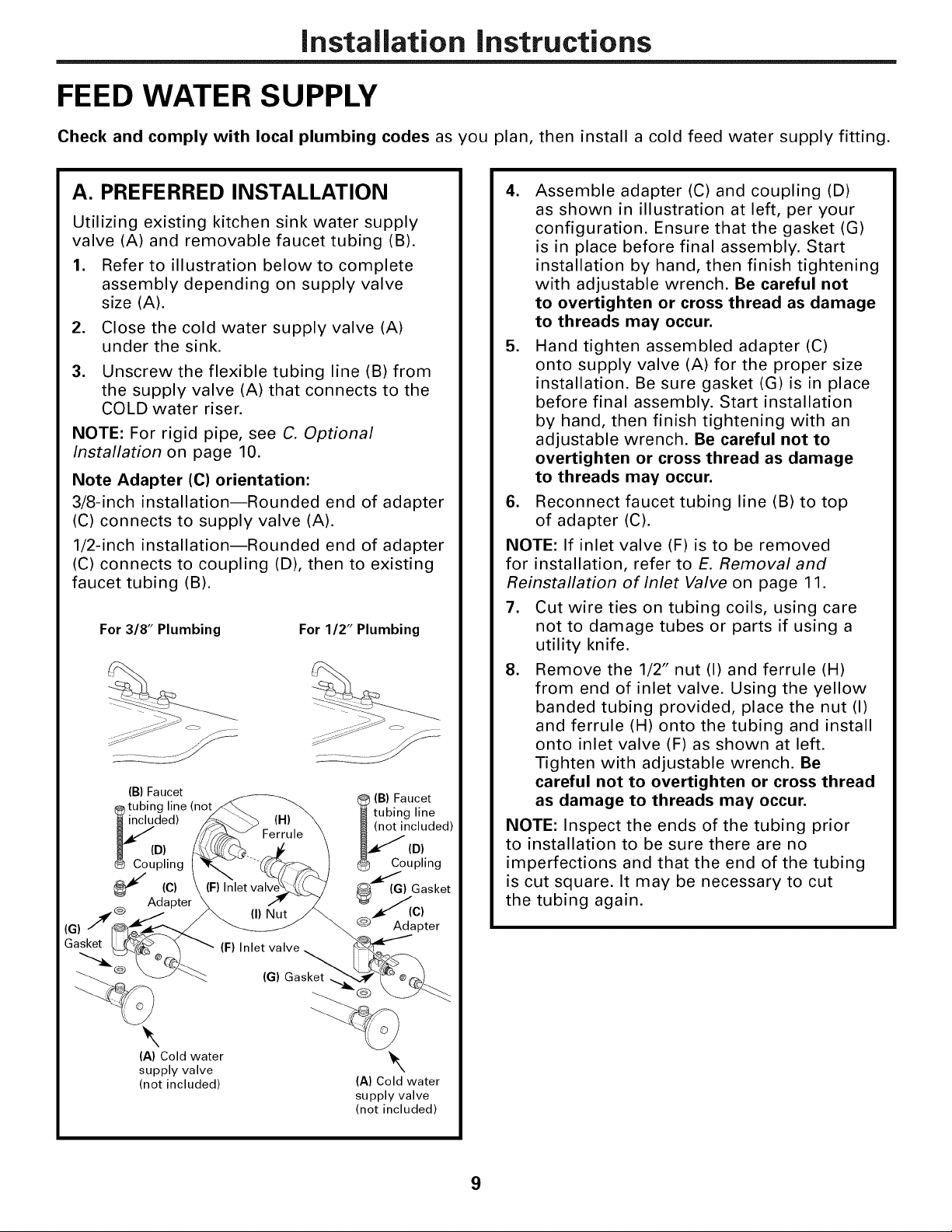
Note Adapter (C) orientation:
3/8-inch installation--Rounded end of adapter
(C) connects to supply valve (A).
1/2-inch installation--Rounded end of adapter
(C) connects to coupling (D), then to existing
faucet tubing (B).
For 3/8" Plumbing For 1/2" Plumbing
(B) Faucet
tubing line (not
ded)
D)
piing
(c)
@ Adapter
--_/'!__ (I) Nut
(G)
Gasket [L_,_ "_ _ (F) Inlet valve .
(B) Faucet
tubing line
_) Gasket
@_A d(C_ter
cluded)
D)
upling
4. Assemble adapter (C) and coupling (D)
as shown in illustration at left, per your
configuration. Ensure that the gasket (G)
is in place before final assembly. Start
installation by hand, then finish tightening
with adjustable wrench. Be careful not
to overtighten or cross thread as damage
to threads may occur.
5. Hand tighten assembled adapter (C)
onto supply valve (A) for the proper size
installation. Be sure gasket (G) is in place
before final assembly. Start installation
by hand, then finish tightening with an
adjustable wrench. Be careful not to
overtighten or cross thread as damage
to threads may occur.
6. Reconnect faucet tubing line (B) to top
of adapter (C).
NOTE: If inlet valve (F) is to be removed
for installation, refer to E. Removal and
Reinstallation of Inlet Valve on page 11.
7. Cut wire ties on tubing coils, using care
not to damage tubes or parts if using a
utility knife.
8. Remove the 1/2" nut (I) and ferrule (H)
from end of inlet valve. Using the yellow
banded tubing provided, place the nut (I)
and ferrule (H) onto the tubing and install
onto inlet valve (F) as shown at left.
Tighten with adjustable wrench. Be
careful not to overtighten or cross thread
as damage to threads may occur.
NOTE: Inspect the ends of the tubing prior
to installation to be sure there are no
imperfections and that the end of the tubing
is cut square. It may be necessary to cut
the tubing again.
_Q'_ (G) Gasket
\
(A) Cold water
supply valve
(not included)
\
(A) Cold water
supply valve
(not included)
9
Installation instructions
FEED WATER SUPPLY (cont.)
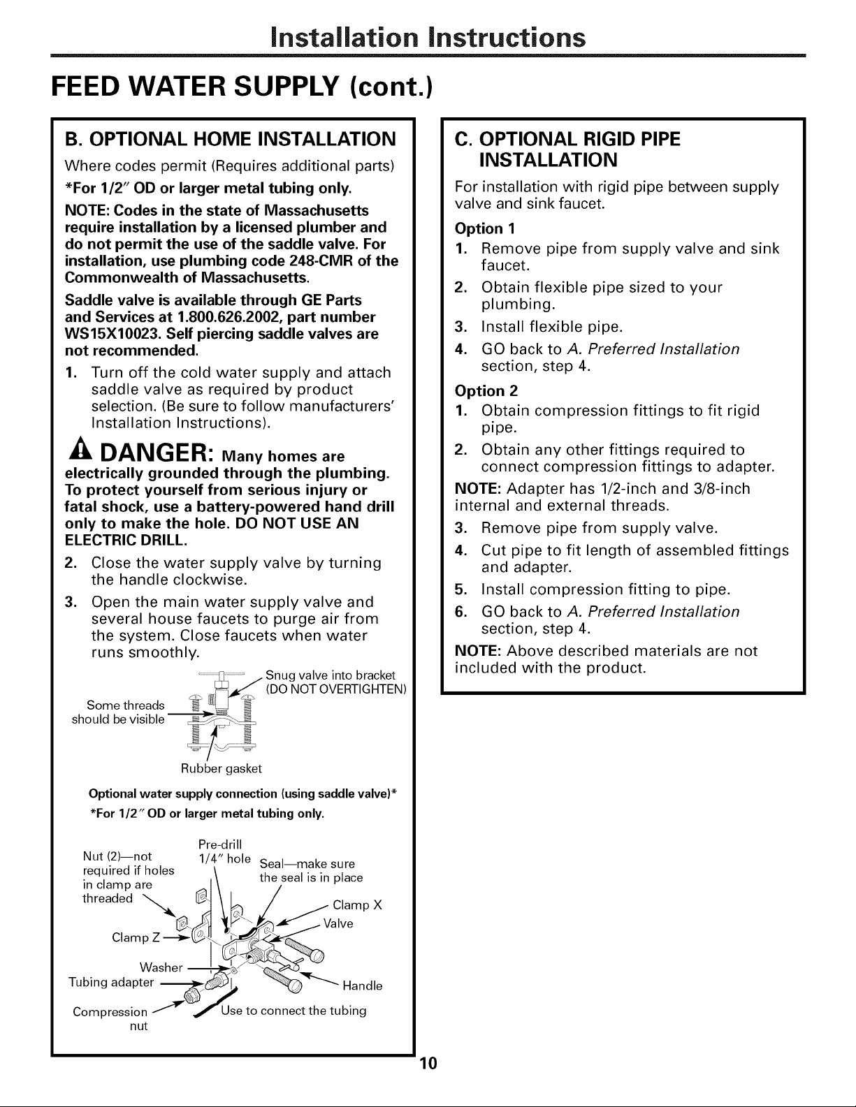
B. OPTIONAL HOME INSTALLATION
Where codes permit (Requires additional parts)
*For 1/2" OD or larger metal tubing only.
NOTE: Codes in the state of Massachusetts
require installation by a licensed plumber and
do not permit the use of the saddle valve. For
installation, use plumbing code 248-CMR of the
Commonwealth of Massachusetts.
Saddle valve is available through GE Parts
and Services at 1.800.626.2002, part number
WS15X10023. Self piercing saddle valves are
not recommended.
1. Turn off the cold water supply and attach
saddle valve as required by product
selection. (Be sure to follow manufacturers'
Installation Instructions).
-& DANGER: Many homes are
electrically grounded through the plumbing.
To protect yourself from serious injury or
fatal shock, use a battery-powered hand drill
only to make the hole. DO NOT USE AN
ELECTRIC DRILL.
.
Close the water supply valve by turning
the handle clockwise.
3.
Open the main water supply valve and
several house faucets to purge air from
the system. Close faucets when water
runs smoothly.
Snug valve into bracket
(DO NOT OVERTIGHTEN)
C. OPTIONAL RIGID PIPE
INSTALLATION
For installation with rigid pipe between supply
valve and sink faucet.
Option 1
1. Remove pipe from supply valve and sink
faucet.
2. Obtain flexible pipe sized to your
plumbing.
3. Install flexible pipe.
4. GO back to A. Preferred Installation
section, step 4.
Option 2
1. Obtain compression fittings to fit rigid
pipe.
2. Obtain any other fittings required to
connect compression fittings to adapter.
NOTE: Adapter has 1/2-inch and 3/8-inch
internal and external threads.
3. Remove pipe from supply valve.
4. Cut pipe to fit length of assembled fittings
and adapter.
5. Install compression fitting to pipe.
6. GO back to A. Preferred Installation
section, step 4.
NOTE: Above described materials are not
included with the product.
Rubber gasket
Optional water supply connection (using saddle valve)*
*For 1/2" OD or larger metal tubing only.
Nut (2)--not
required if holes
in clamp are
threaded "'_O-
Clam
Washer --
Tubing adapter
Compression
nut
Pre-drill
1/4" hole Seal--make sure
the seal is in place
Use to connect the tubing
10

Installation instructions
D. OPTIONAL REMOTE LOCATION
INSTALLATION
(requires additional part)
1. Turn off the cold water supply.
2. Complying with plumbing codes, install a
fitting on the cold water pipe to adapt 1/4"
OD tubing. A typical connection is shown
in illustration below. Make sure a water
supply valve is used.
3. If the RO unit is to be installed more than
6 feet from the valve, replace the yellow
banded inlet tubing with a longer length
of GE 1/4" tubing. A 33 foot length of 1/4"
tubing is available through GE Parts and
Services at 1.800.626.2002, part number
WS07X10018. DO NOT SUBSTITUTE
TUBING OF UNKNOWN QUALITY.
. If the RO unit is to be installed more than
6 feet from the faucet, replace the blue
banded outlet tubing with a longer length
of GE 3/8" tubing. A 33 foot length is
available through GE Parts and Services at
1.800.626.2002, part number WS07X10019.
See Faucet Installation on page 13 for more
details. DO NOT SUBSTITUTE TUBING OF
UNKNOWN QUALITY.
Preferred water supply connection
(using compression fitting)
Water supply valve
Insert (not included)
Cold
RO
pipe
1/4" (yellow banded) _4-_,_"4_ _
tubing to inlet
E. REMOVAL AND RE-INSTALLATION
OF INLET VALVE (required only if
inlet valve needs to be removed to
complete Step 5 on page 13)
1. Remove inlet valve (F) from adapter (C)
using adjustable wrench on valve body.
See illustration below for detail. DO NOT
USE WRENCH ON HEX NUT END OF
VALVE AS LEAK MAY OCCUR.
(c)
(F) Inlet valve
2. Remove all sealing tape from inlet valve
(F) and adapter (C) threads.
3. Hand tighten assembled adapter (C)
onto supply valve (A) for the proper size
installation. Be sure the gaskets (G), as
shown on page 13, are in place before
final assembly. Finish tightening with
adjustable wrench. Be careful not to
overtighten or cross thread as damage
to threads may occur.
4. Using white thread sealing tape provided,
apply approximately 9 wraps of tape
around the large threads on inlet valve (F)
in a clockwise direction, as shown below.
If you are using copper tubing, DO NOT
connect it directly onto the RO unit. Purchase a
connector and use a short length of the yellow
banded tubing provided to make final connection
to RO. Do not use copper tubing to attach to
icemaker or faucet.
11
.
Hand tighten inlet valve (F) into the adapter
(C), then finish tightening with adjustable
wrench. DO NOT USE WRENCH ON HEX
NUT END OF VALVE AS LEAK MAY OCCUR.
Installation instructions
TUBING AND FLOW RESTRICTOR INSTALLATION
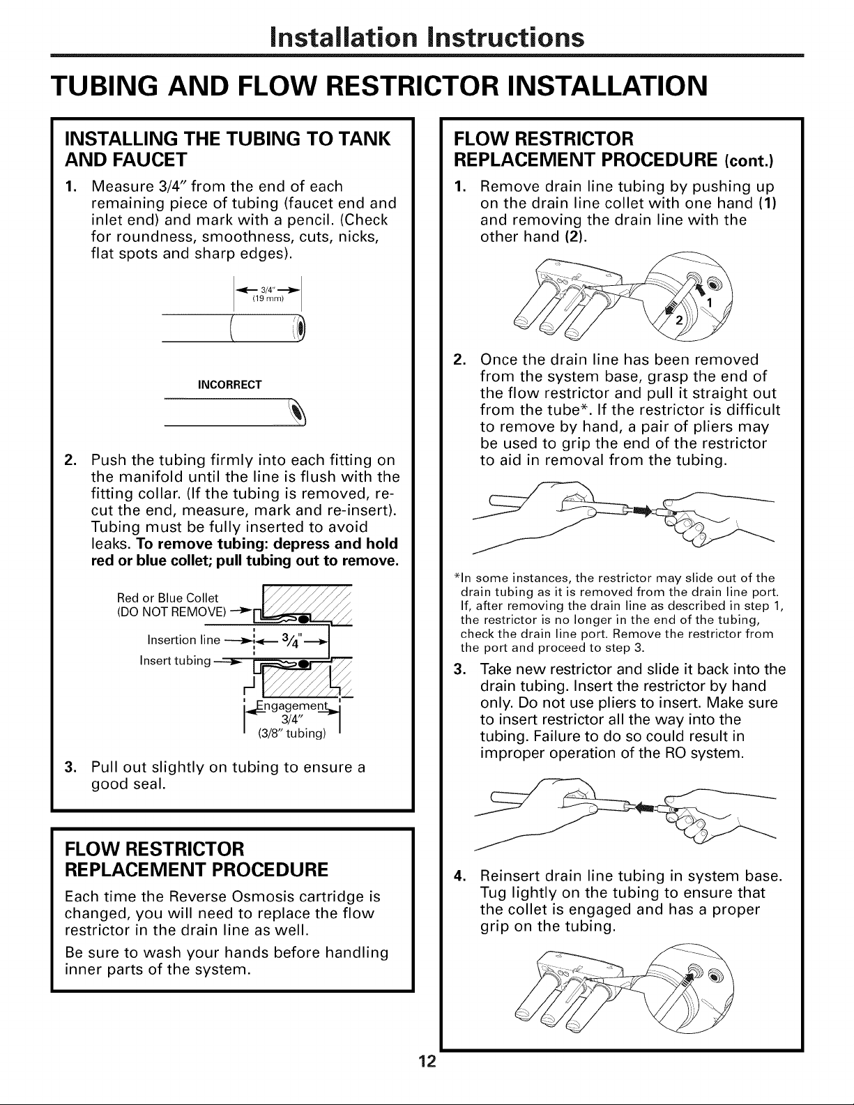
INSTALLING THE TUBING TO TANK
AND FAUCET
.
Measure 3/4" from the end of each
remaining piece of tubing (faucet end and
inlet end) and mark with a pencil. (Check
for roundness, smoothness, cuts, nicks,
flat spots and sharp edges).
3/4"
19 mm
INCORRECT
.
Push the tubing firmly into each fitting on
the manifold until the line is flush with the
fitting collar. (If the tubing is removed, re-
cut the end, measure, mark and re-insert).
Tubing must be fully inserted to avoid
leaks. To remove tubing: depress and hold
red or blue collet; pull tubing out to remove.
/ /
Red or Blue Collet F_
(DO NOT REMOVE) --__
Insertion line _ 3/4"._
Insert tubing ----_ _l_'?-
i
i
i
ngagement-_
3/4" --
/8" tubing)
.
Pul out slightly on tubing to ensure a
good seal.
//
/
FLOW RESTRICTOR
REPLACEMENT PROCEDURE (cont.)
.
Remove drain line tubing by pushing up
on the drain line collet with one hand (1)
and removing the drain line with the
other hand (2).
. Once the drain line has been removed
from the system base, grasp the end of
the flow restrictor and pull it straight out
from the tube*. If the restrictor is difficult
to remove by hand, a pair of pliers may
be used to grip the end of the restrictor
to aid in removal from the tubing.
*In some instances, the restrictor may slide out of the
drain tubing as it is removed from the drain line port.
If, after removing the drain line as described in step 1,
the restrictor is no longer in the end of the tubing,
check the drain line port. Remove the restrictor from
the port and proceed to step 3.
3. Take new restrictor and slide it back into the
drain tubing. Insert the restrictor by hand
only. Do not use pliers to insert. Make sure
to insert restrictor all the way into the
tubing. Failure to do so could result in
improper operation of the RO system.
FLOW RESTRICTOR
REPLACEMENT PROCEDURE
Each time the Reverse Osmosis cartridge is
changed, you will need to replace the flow
restrictor in the drain line as well.
Be sure to wash your hands before handling
inner parts of the system.
12
.
Reinsert drain line tubing in system base.
Tug lightly on the tubing to ensure that
the collet is engaged and has a proper
grip on the tubing.
Installation instructions
FAUCET ASSEMBLY
FAUCET MOUNTING INSTALLATION
Be sure there is room underneath the sink to
make the needed connections. Select one of
the following locations to install the faucet:
• In an existing sink spray attachment or soap
dispenser hole.
• In a hole to be drilled in the sink top.
• In a hole to be drilled in the countertop,
next to the sink.
NOTE: Be sure the faucet base will fit flat
against the surface at the selected location
so the gasket will seal.
1. If drilling is needed, make a 1-1/4" dia.
hole. Be sure to use the proper procedure
for drilling porcelain or stainless steel.
Special drill bits may be needed. Consult
a qualified plumber for proper procedure.
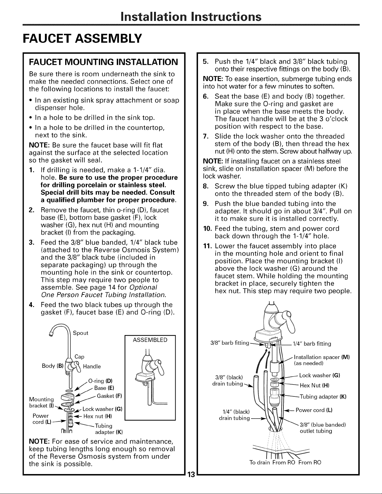
2. Remove the faucet, thin o-ring (D), faucet
base (E), bottom base gasket (F), lock
washer (G), hex nut (H) and mounting
bracket (I) from the packaging.
3. Feed the 3/8" blue banded, 1/4" black tube
(attached to the Reverse Osmosis System)
and the 3/8" black tube (included in
separate packaging) up through the
mounting hole in the sink or countertop.
This step may require two people to
assemble. See page 14 for Optional
One Person Faucet Tubing Installation.
4. Feed the two black tubes up through the
gasket (F), faucet base (E) and O-ring (D).
5. Push the 1/4" black and 3/8" black tubing
onto their respective fittings on the body (B).
NOTE: To ease insertion, submerge tubing ends
into hot water for a few minutes to soften.
6. Seat the base (E) and body (B) together.
Make sure the O-ring and gasket are
in place when the base meets the body.
The faucet handle will be at the 3 o'clock
position with respect to the base.
7. Slide the lock washer onto the threaded
stem of the body (B), then thread the hex
nut (H) onto the stem. Screw about halfway up.
NOTE: If installing faucet on a stainless steel
sink, slide on installation spacer (M) before the
lock washer.
8. Screw the blue tipped tubing adapter (K)
onto the threaded stem of the body (B).
9. Push the blue banded tubing into the
adapter. It should go in about 3/4". Pull on
it to make sure it is installed correctly.
10. Feed the tubing, stem and power cord
back down through the 1-1/4" hole.
11. Lower the faucet assembly into place
in the mounting hole and orient to final
position. Place the mounting bracket (I)
above the lock washer (G) around the
faucet stem. While holding the mounting
bracket in place, securely tighten the
hex nut. This step may require two people.
Spout
ASSEMBLED
Cap
Body (B)
bracket (I)
Mounting
Power I_1-- Hex nut (H)
cord (L) -----_1_ _..
_ Handle
/ O-ring (D)
p_z'/Base (E)
_w- /-Gasket (F)
Lock washer (G)
II_ _--Tubing
I_lln adapter (K)
NOTE: For ease of service and maintenance,
keep tubing lengths long enough so removal
of the Reverse Osmosis system from under
the sink is possible.
13
3/8" barb fittinc
3/8" (black)
drain tubin<
1/4" (black)
drain tubin(
barb fitting
spacer (M)
(as needed)
Lock washer (G)
Nut (H)
g adapter (K)
Power cord (L)
blue banded)
outlet tubing
To drain From RO From RO
Installation instructions
FAUCET ASSEMBLY (cont.)
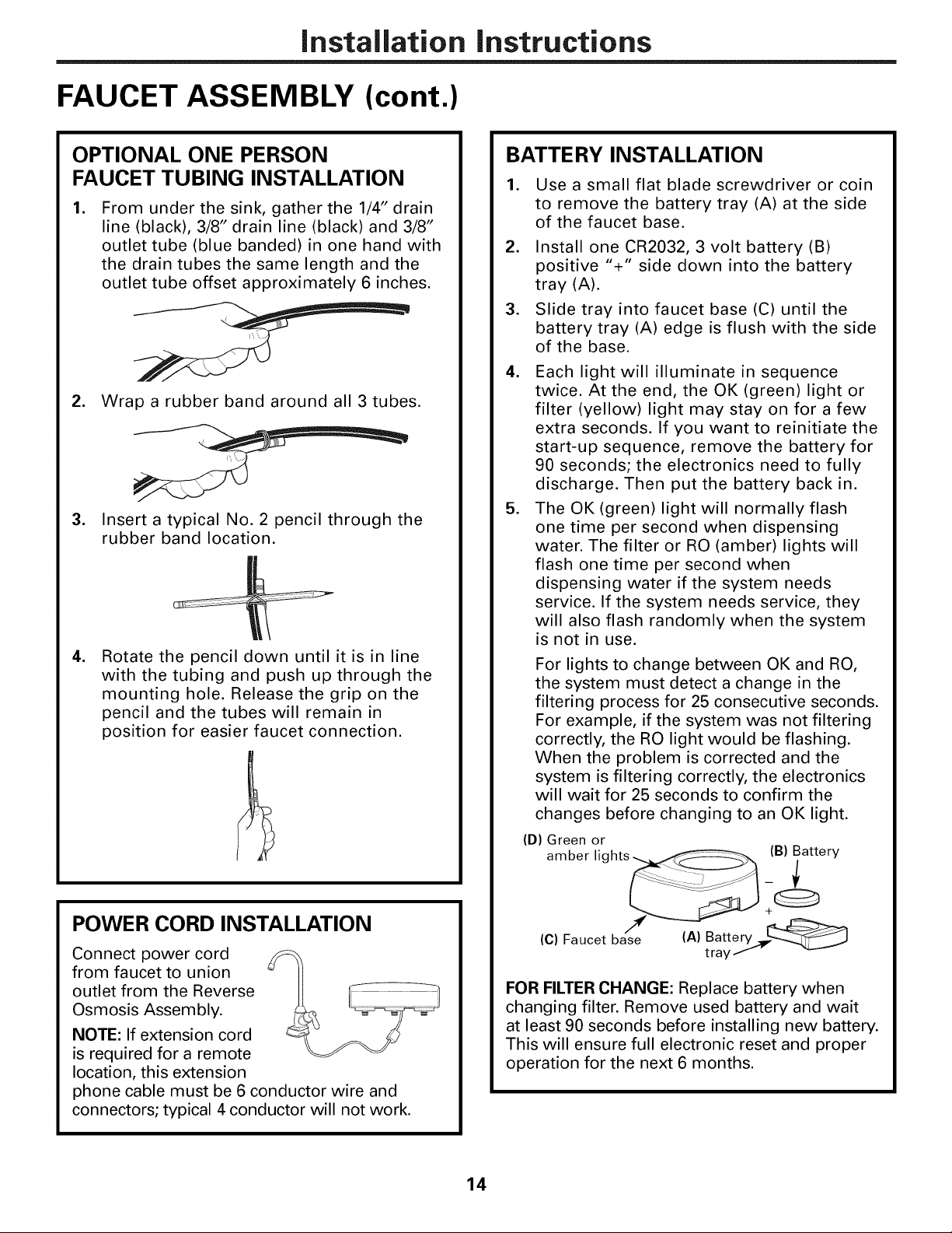
OPTIONAL ONE PERSON
FAUCET TUBING INSTALLATION
,
From under the sink, gather the 1/4" drain
line (black), 3/8" drain line (black) and 3/8"
outlet tube (blue banded) in one hand with
the drain tubes the same length and the
outlet tube offset approximately 6 inches.
2. Wrap a rubber band around all 3 tubes.
,
Insert a typical No. 2 pencil through the
rubber band location.
,
Rotate the pencil down until it is in line
with the tubing and push up through the
mounting hole. Release the grip on the
pencil and the tubes will remain in
position for easier faucet connection.
BATTERY INSTALLATION
, Use a small flat blade screwdriver or coin
to remove the battery tray (A) at the side
of the faucet base.
2. Install one CR2032, 3 volt battery (B)
positive "+" side down into the battery
tray (A).
3. Slide tray into faucet base (C) until the
battery tray (A) edge is flush with the side
of the base.
4. Each light will illuminate in sequence
twice. At the end, the OK (green) light or
filter (yellow) light may stay on for a few
extra seconds. If you want to reinitiate the
start-up sequence, remove the battery for
90 seconds; the electronics need to fully
discharge. Then put the battery back in.
5. The OK (green) light will normally flash
one time per second when dispensing
water. The filter or RO (amber) lights will
flash one time per second when
dispensing water if the system needs
service. If the system needs service, they
will also flash randomly when the system
is not in use.
For lights to change between OK and RO,
the system must detect a change in the
filtering process for 25 consecutive seconds.
For example, if the system was not filtering
correctly, the RO light would be flashing.
When the problem is corrected and the
system is filtering correctly, the electronics
will wait for 25 seconds to confirm the
changes before changing to an OK light.
(D) Green or
POWER CORD INSTALLATION
Connect power cord
from faucet to union
outlet from the Reverse
Osmosis Assembly.
NOTE: If extension cord
is required for a remote
location, this extension
phone cable must be 6 conductor wire and
connectors; typical 4 conductor will not work.
amber lights_ i_ery
A Batter
(C) Faucet base ( ) tray.S- _
FOR FILTER CHANGE: Replace battery when
changing filter. Remove used battery and wait
at least 90 seconds before installing new battery.
This will ensure full electronic reset and proper
operation for the next 6 months.
14
Installation instructions
FILTRATION DRAIN CONNECTION
Check and comply with local plumbing codes as you plan.
-& CAUTION: The options detailed below are the ONLY approved installation
configurations. Do not use any drain saddle device.
NOTE: Failure to follow these Installation Instructions will void the warranty, and the installer will
be responsible for any service, repair or damages caused thereby.
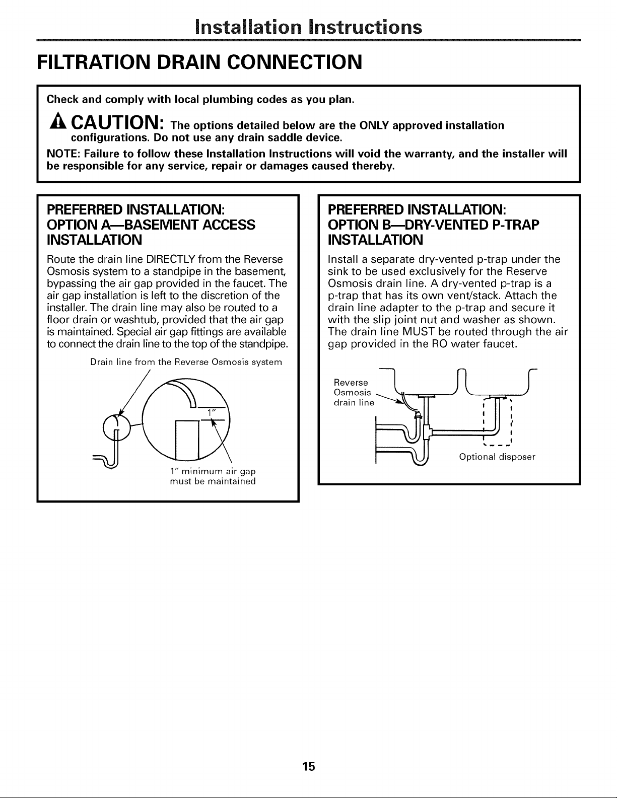
PREFERRED INSTALLATION:
OPTION A--BASEIVIENT ACCESS
INSTALLATION
Route the drain line DIRECTLY from the Reverse
Osmosis system to a standpipe in the basement,
bypassing the air gap provided in the faucet. The
air gap installation is left to the discretion of the
installer. The drain line may also be routed to a
floor drain or washtub, provided that the air gap
is maintained. Special air gap fittings are available
to connect the drain line to the top of the standpipe.
Drain line from the Reverse Osmosis system
1" minimum air gap
must be maintained
PREFERRED INSTALLATION:
OPTION B_DRY-VENTED P-TRAP
INSTALLATION
Install a separate dry-vented p-trap under the
sink to be used exclusively for the Reserve
Osmosis drain line. A dry-vented p-trap is a
p-trap that has its own vent/stack. Attach the
drain line adapter to the p-trap and secure it
with the slip joint nut and washer as shown.
The drain line MUST be routed through the air
gap provided in the RO water faucet.
ReveroSes_--'-'L_
I I
I
I
drain line_
I I
Optional disposer
15
Installation instructions
FILTRATION DRAIN CONNECTION (cont.)
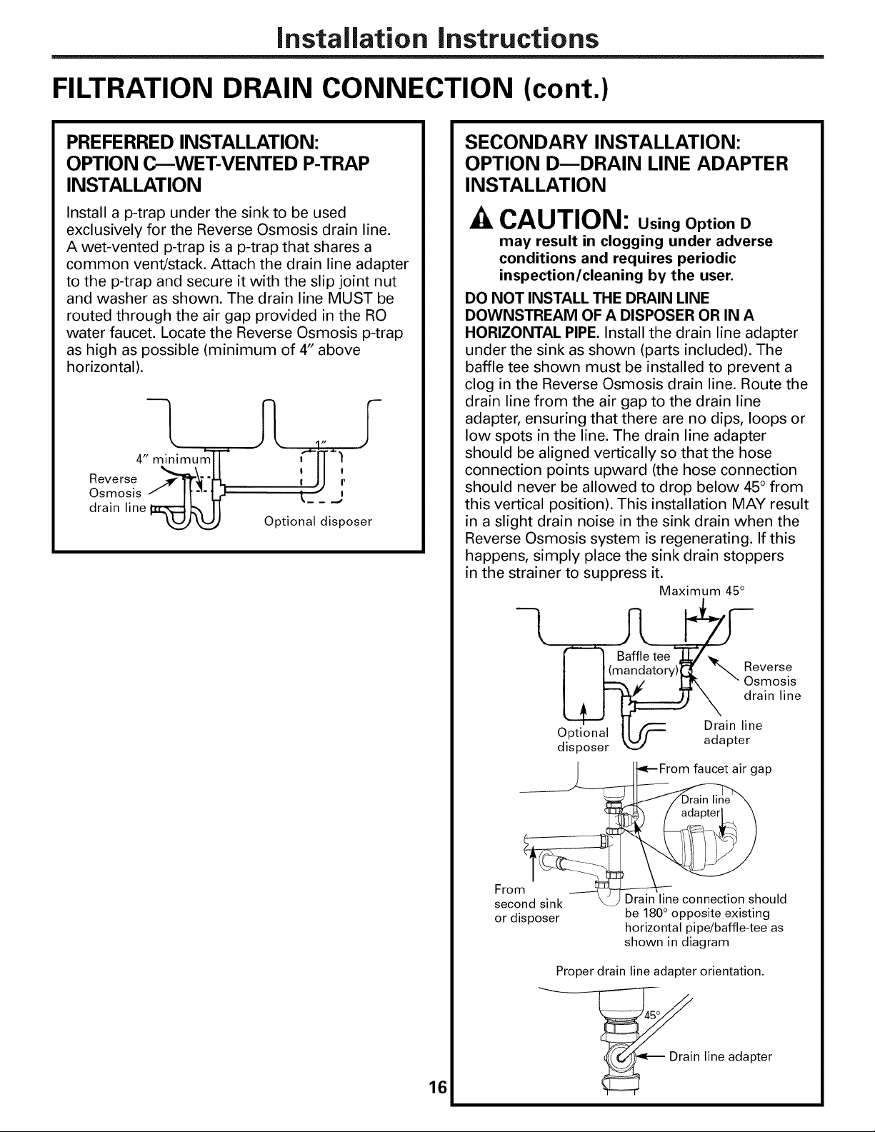
PREFERRED INSTALLATION:
OPTION C_WET-VENTED P-TRAP
INSTALLATION
Install a p-trap under the sink to be used
exclusively for the Reverse Osmosis drain line.
A wet-vented p-trap is a p-trap that shares a
common vent/stack. Attach the drain line adapter
to the p-trap and secure it with the slip joint nut
and washer as shown. The drain line MUST be
routed through the air gap provided in the RO
water faucet. Locate the Reverse Osmosis p-trap
as high as possible (minimum of 4" above
horizontal).
1 tz
4" minimum'T[" i'_-n--)
Reverse _--_[tr_ -ii-iiq : JJ 1,
Osmosis / I['_" Lr I -- i
drain line IzL--_ b, II t_ _ _,
WJLUJ
Optional disposer
SECONDARY INSTALLATION:
OPTION DmDRAIN LINE ADAPTER
INSTALLATION
CAUTION: Using Option D
may result in clogging under adverse
conditions and requires periodic
inspection/cleaning by the user.
DO NOT INSTALL THE DRAIN LINE
DOWNSTREAM OF A DISPOSER OR IN A
HORIZONTAL PIPE. Install the drain line adapter
under the sink as shown (parts included). The
baffle tee shown must be installed to prevent a
clog in the Reverse Osmosis drain line. Route the
drain line from the air gap to the drain line
adapter, ensuring that there are no dips, loops or
low spots in the line. The drain line adapter
should be aligned vertically so that the hose
connection points upward (the hose connection
should never be allowed to drop below 45° from
this vertical position). This installation MAY result
in a slight drain noise in the sink drain when the
Reverse Osmosis system is regenerating. If this
happens, simply place the sink drain stoppers
in the strainer to suppress it.
Maximum 45°
_ , II f-'- Drain line
Uptlonal II t(--- ]._: .
,.' U_')' aaapl:er
alsposer v
Fro
second sink _-_,
or disposer
Proper drain line adapter orientation.
Baffle tee _-7
ndatory)_ Reverse
Osmosis
drain line
_From faucet air gap
Drain line connection should
be 180 ° opposite existing
horizontal pipe/baffle-tee as
shown in diagram
16
_ Drain line adapter
Installation instructions
STORAGE TANK AND STARTUP
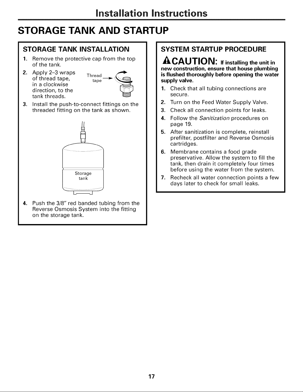
STORAGE TANK INSTALLATION
.
Remove the protective cap from the top
of the tank.
2.
Apply 2-3 wraps
of thread tape,
in a clockwise
direction, to the
tank threads.
.
Install the push-to-connect fittings on the
threaded fitting on the tank as shown.
Thread
tape
Storage
tank
SYSTEM STARTUP PROCEDURE
-&CAUTION: if installing the unit in
new construction, ensure that house plumbing
is flushed thoroughly before opening the water
supply valve.
1. Check that all tubing connections are
secure.
2. Turn on the Feed Water Supply Valve.
3. Check all connection points for leaks.
4. Follow the Sanitization procedures on
page 19.
5. After sanitization is complete, reinstall
prefilter, postfilter and Reverse Osmosis
cartridges.
6. Membrane contains a food grade
preservative. Allow the system to fill the
tank, then drain it completely four times
before using the water from the system.
7. Recheck all water connection points a few
days later to check for small leaks.
4. Push the 3/8" red banded tubing from the
Reverse Osmosis System into the fitting
on the storage tank.
17
Careand cleaningof the reverse osmosissystem.
Prefilter, Postfilter and Reverse Osmosis Membrane Cartridge Replacement Procedure
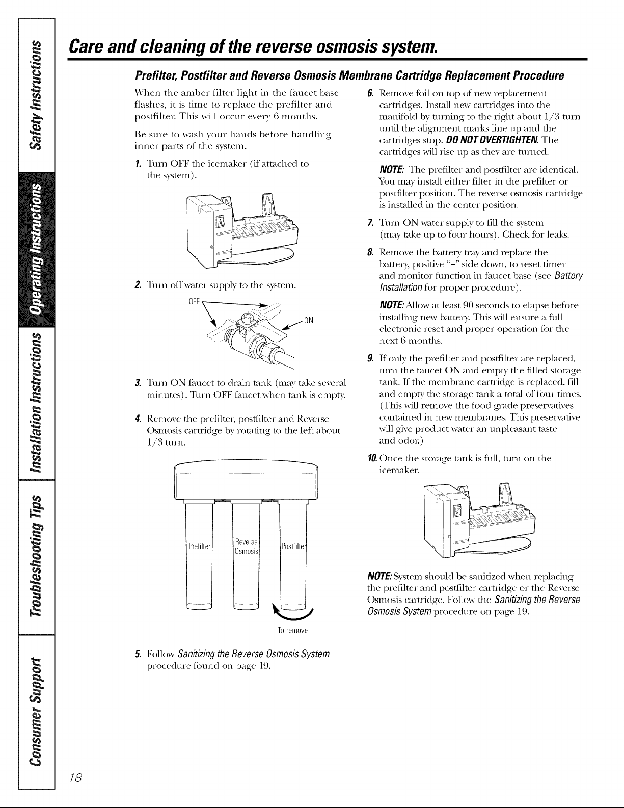
When the amber filter light in the faucet base
flashes, it is time to replace tim prefilter and
postfilteL This will occur every 6 months.
Be sure to wash your hands before handling
inner parts of the system.
1. Turn OFF file icemaker (if attached to
file sysmm).
2.
Turn offwater supply m file sysmm.
6.
Remove foil on top of new replacement
cam_idges. Install new cam_idges into the
manifold by turning to the right about 1/3 turn
until the alignment marks line up and the
cartridges stop. DONOT0VERnSHTEN.The
cam-idges will rise up as they are turned.
NOTE:The prefilter and postfilter are identical.
You mW install either filmr in the prefilter or
postfilmr position. The reverse osmosis cartridge
is installed in tile cenmr position.
Z
Turn ON wamr supply to fill file sysmm
(may take up to four hours). Check for leaks.
8.
Remove die battery tray and replace die
baEery, positive "+" side down, to reset timer
and monitor flmcfion in faucet base (see Battery
Installation for proper procedure).
OFF ._........-5:)
,,-"-:: "};i:K'-/" ON
3.
Turn ON faucet m drMn rank (may take seve_M
minutes). Turn OFF faucet when rank is empty.
4. Remove tile prefilmi; postfilter and Reveise
Osmosis camidge by romdng m tile left about
1/3 turn.
To remove
NOTE:Allowat least 90 seconds to elapse before
installing new battery. This will ensure a dill
elecnonic reset and proper operation for the
next 6 months.
9.
If only die prefilmr and postfilmr are replaced,
mrn the faucet ON and empty the flled storage
rank. If the membrane camidge is replaced, fill
and empty the storage rank a mt_fl of four times.
(This will remove the food grade preset, retires
contained in new membranes. This preservative
will gNe product wamr an unpleasant taste
and odoL)
10.Once die storage rank is full, mrn on die
icemakeL
NOTE:System should be sanitized when replacing
the prefilmr and postfilter cam_idge or the Reverse
Osmosis cartridge. Follow tlle Sanitizingthe Reverse
Osmosis System procedure on page 19.
18
5. Follow Sanitizing the Reverse Osmosis System
procedure found on page 19.
Sanitizing the Reverse Osmosis System
Sanitize upon installation of the Reverse Osmosis
systeIIl and after servicing inner parts, including
replacement of prefilter, postfilter and the
membrane cartridge.
Be sure to wash your hands beffne handling
inner parts of the system.
CAUTION'.Be ,,esa.itiz., ,t,es.,eto
remove all cartridges. Chlorine will destroy the
Reverse Osmosis membrane camidge.
E Follow steps 1 through 4 under Profiltor,
PostfilterandReverseOsmosisMembraneCartridge
ReplacementProcedure.
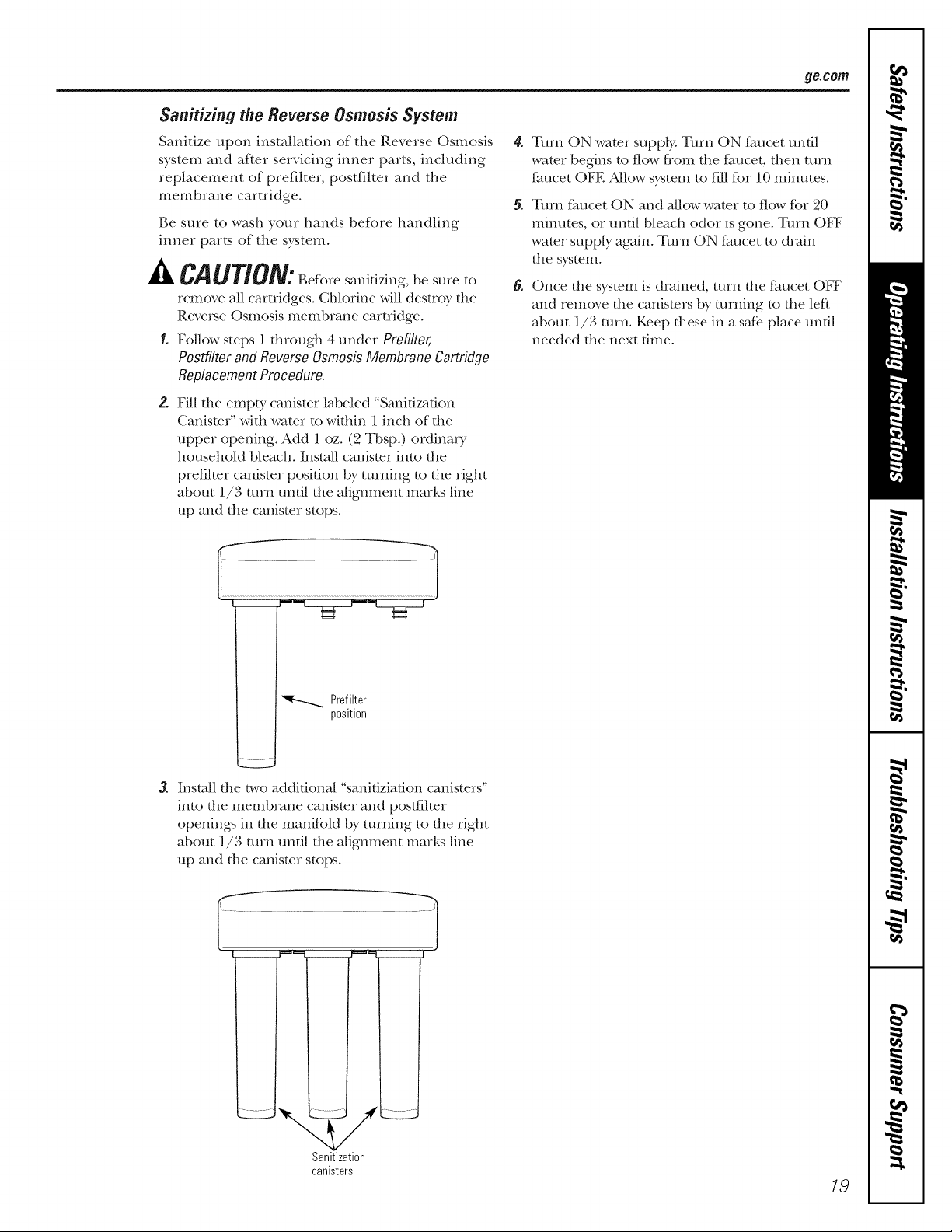
2. Fill die empty canister labeled "Sanidzadon
Canismr" with water to within 1inch of the
upper opening. Add 1 oz. (2 Tbsp.) ordinm T
household bleach. Install canister into the
prefilter canismr posidon by turning to the right
about 1/3 mrn undl the alignment marks line
up and the canismr stops.
ge.com
Turn ON water supply. Turn ON faucet until
water begins to flow fiom the faucet, then turn
faucet OFE Allow system to fill for 10 minutes.
Tmn faucet ON and allow water to flow ff_r 20
minutes, or until bleach odor is gone. Turn OFF
water supply again. Turn ON faucet to drain
the sysmm.
Once file sysmm is drained, turn file faucet OFF
and remove file canisters by turning to the left
about 1/3 turn. Keep dlese in a safe. place until
needed file next time.
Prefilter
position
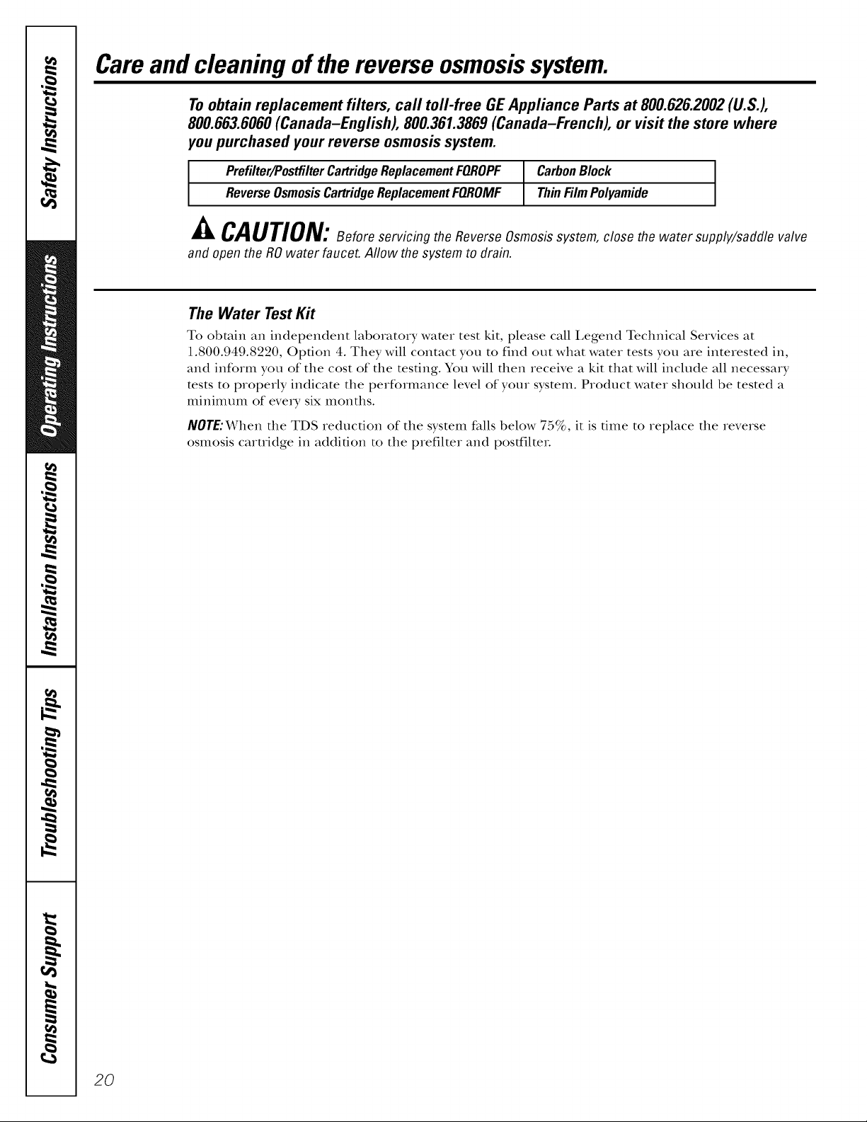
3. Install the two additional "sanifiziafion canl_te_'ss'
into the membrane canister and posffilter
openings in the manifold by turning to the right
about 1l/3 turn until the alignment marks line
up and the canister stops.
/
Sanitization
canisters
19
Careand cleaningof the reverse osmosissystem.
To obtain replacement filters, call toll-free GE Appliance Parts at 800.626.2002 (U.S.),
800.663.6060 (Canada-English), 800.361.3869 (Canada-French), or visit the store where
you purchased your reverse osmosis system.
Prefilter/Postfilter Cartridge Replacement FQROPF CarbonBlock
Reverse OsmosisCartridge Replacement FQROMF Thin FilmPolyamide
CAUTION:BeforeservicingtheReverseOsmosissystem,closethewatersupplyJsaddlevalve
anti open the RO water faucet. Allow the system to flrain.
The Water TestKit
To obtain an independent laboratory water test kit, please call I,egend Technical Services at
1.800.949.8220, Option 4. They will contact you to find out what water tests you are interested in,
and inform you of the cost of the testing. You will then receive a kit that will include all necessary
tests to property indicate the performance level of your system. Product water should be tested a
minimum of eve_T six months.
NOTE:When the TDS reduction of the system fidls below 75%, it is dine to replace the reverse
osmosis cartridge in addition to the prefilter and postfilteL
20
Before you call for service.., ge.cem
Troubleshooting 77ps
Save time and money! Review the charts on the following
pages first and you may not need to call for service.
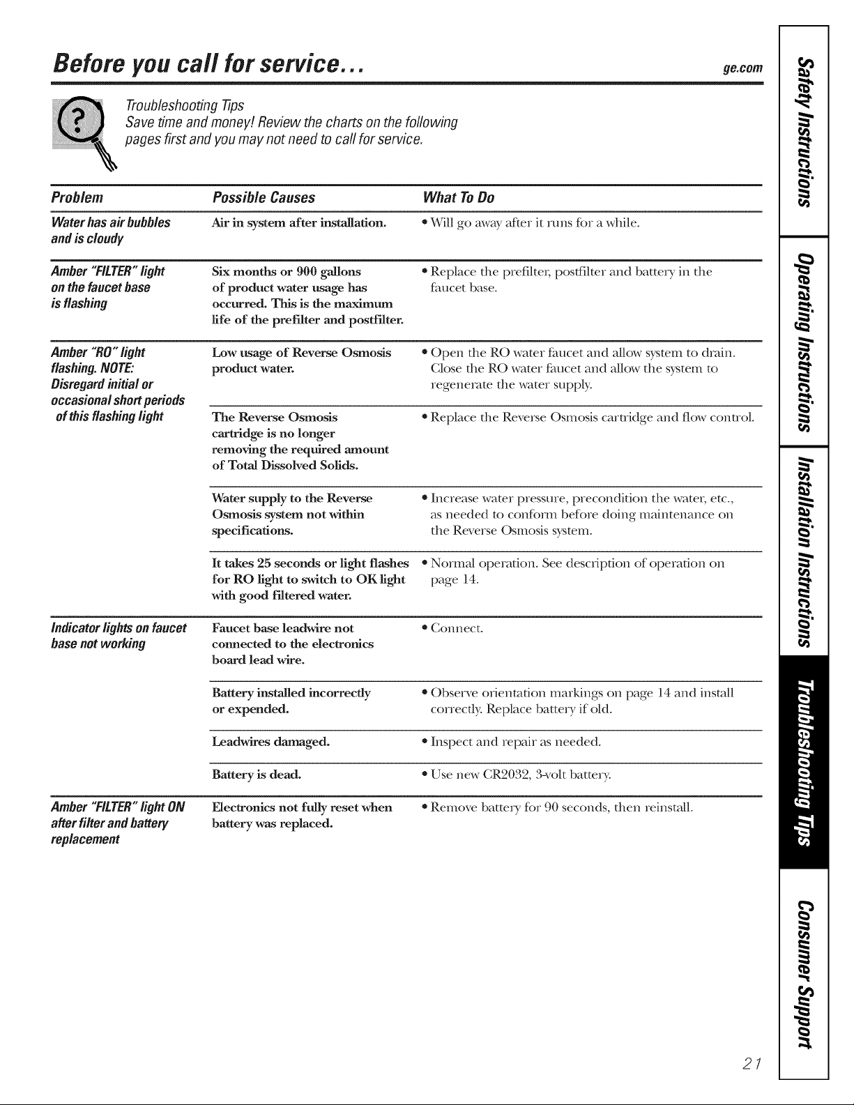
Problem Possible Causes What ToBe
Water has air bubbles Air in system after installation. * Will go away after k runs for a while°
and is cloudy
Amber"FILTER"light
onthefaucetbase
is flashing
Amber"RO"light
flashing. NOTE:
Disregard initialor
Six months or 900 gallons
of product water usage has
occurred. This is the maximum
life of the prefilter and postfilter.
Low usage of Reverse Osmosis
product water.
• Replace dte prefilteL postfilter and batte_ T ht the
faucet base°
• Open fire Re water faucet and allow system to drain°
Close rite Re water faucet and allow the system to
regenerate rite water supply°
occasionalshortperiods
ofthisflashinglight
indicator lights on faucet Faucet base leadwire not * Connect.
base not working connected to the electronics
The Reverse Osmosis
cartridge is no longer
removing the required amount
of Total Dissolved Solids.
Water supply to the Reverse
Osmosis system not within
specifications.
It takes 25 seconds or light flashes * Normal operation. See description of operation on
for Re light to switch to OK light page 14.
with good filtered water.
board lead wire.
* Replace rite Reve_e Osmosis cartridge and flow control
* Increase water pressure, precondition the watex; etc.,
as needed to conform before doing maintenance on
the Reverse Osmosis system°
Battery installed incorrectly * Observe orientation markings on page 14 and install
or expended, correctly. Replace batte W if old.
Leadwires damaged. * Inspect and repah as needed.
Battery is dead. * Use new CR2032, 3-volt battery.
Amber"FILTER"I_ghtON Electronics not fully reset when * Remove batte W for 90 seconds, then reinstall.
after filter and battery battery was replaced.
replacement
21
Before you call for service...
Troubleshooting -tips
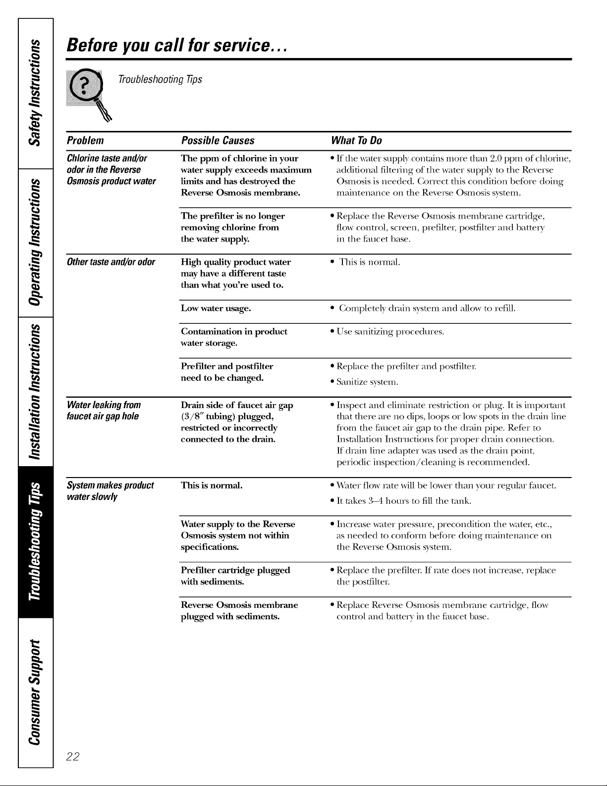
Problem
Chlorinetasteand/or
odorintheReverse
Osmosisproductwater
Othertasteand/orodor
Waterleakingfrom
faucetairgaphole
Possible Causes What ToDo
The ppm of chlorine in your
water supply exceeds maximum
limits and has destroyed the
Reverse Osmosis membrane.
The prefilter is no longer
removing chlorine from
the water supply.
High quality product water
may have a different taste
than what you're used to.
• ff the water supply contains more than 9.0 ppm of chlorine,
additional filmfing of the wamr supply m the Reverse
Osmosis is needed. Gorrect this condition before doing
maintenance on the Reverse Osmosis sysmm.
• Replace file Reveise Osmosis membrane caruidge,
flow control, screen, prefilte_, postfilmr and batm_T
in the faucet base.
• This is normal.
Low water usage. • Gomplemly drain sysmm and allow m refill.
Contamination in product • Use sanitizing procedures.
water storage.
Prefilter and postfilter • Replace the prefilter and posttilte_:
need to be changed. * Sanitize system.
Drain side of faucet air gap
(3/8" tubing) plugged,
restricted or incorrectly
connected to the drain.
• Inspect and eliminam resuicdon or plug. It is important
that there are no dips, loops or low spots in the drain line
flom the faucet air gap m the drain pipe. Refer m
Installation Insn-ucdons for proper drain connection.
If drain line adaptor was used as the drain point,
periodic inspec6on/cleaning is recommended.
Systemmakesproduct
waterslowly
22
This is normal.
• Water flow rote will be lower dlan your regular faucet.
• It takes ,3-4 hours m fill the rank.
Water supply to the Reverse
Osmosis system not within
specifications.
• Increase water pressure, precondition file wateL etc.,
as needed m conform before doing mainmnance on
the Reverse Osmosis sysmm.
Pref'dter cartridge plugged • Replace the prefilteL If rate does not increase, replace
with sediments, the postfilteL
Reverse Osmosis membrane
plugged with sediments.
• Replace Reverse Osmosis membrane cartridge, flow
control and batte U in the faucet base.

Commonproblems associated with filter
or RO cartridge replacement. ge.com
Troubleshooting -tips
Problem Possible Causes What ToDo
NOWater Water supply valve *Turn water supply valve on. See diagram on page 11.
not turned on.
After f'dter change, * It takes 3-4 hotn_ for RO system to provide enough
tank is empty, water to fill the tank.
Leaksat fittings Improperly installed. *Reinstall. See Installation Instructions.
Sounds you may hear Sink drain, drain water * Tiffs is nommL
from system.
• Drain line can be installed to an alternative drain,
such as a basement drain. See pages 15 and 16
for almrnative drain configurations.
Faucet air gap--drain water
flowing through the faucet
air gap. This may be assodated
with high pressure water supply,
generally 90 psi or greater.
*Install a pressure regulator in die house wamr supply
system to reduce the pressure below 90 psi.
*An almrnative flow restrictor for high pressure
installations is avaihble flom GE (see item #31 on the
parts list, page 25). Contact GE Parts and ask for Flow
Restficto_, High Pressure, Part Number WS15X10049.
23
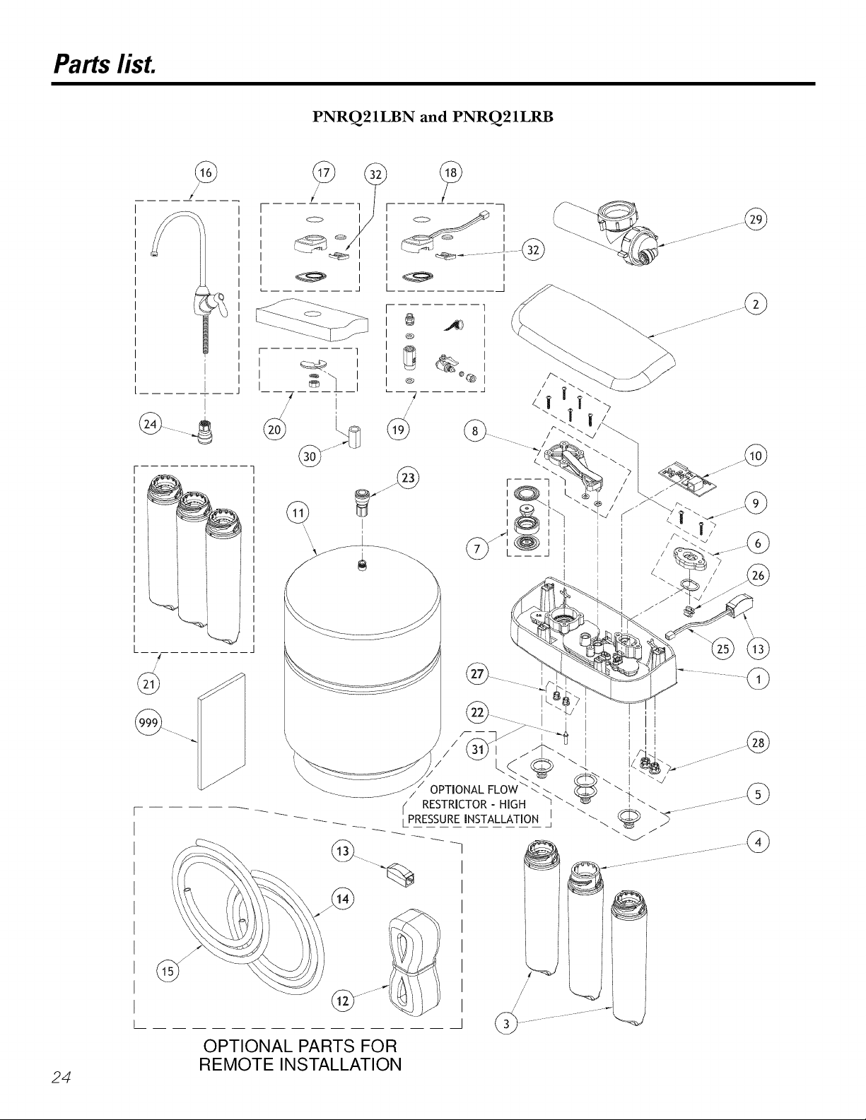
Parts lisL
PNRQ21LBN and PNRQ21LRB
r 1
I c_ I
I _'_
/ I
_Q_J
@
I I I
I
@
@
---7
/
/
/
I
I
I
I
I
I
24
@
/
/
@
/
/
/
/
-,
OPTIONAL PARTS FOR
REMOTE INSTALLATION
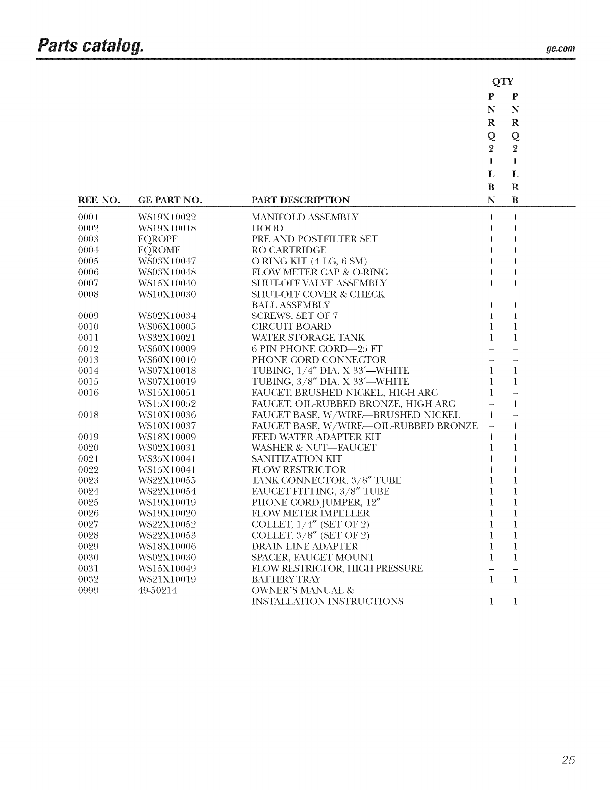
Parts cata/og, ge.o,
QTY
P P
N N
R R
Q Q
2 2
1 1
L L
B R
REE NO. GE PART NO.
0001 WS19X10022
0002 WS19X10018
0003 FQROPF
0004 FQROMF
0005 WS03X10047
0006 WS03X10048
0007 WS15X10040
0008 WS10X10030
0009 WS02X10034
0010 WS06X 10005
0011 WS32X10021
0012 WS60X 10009
0013 WS60X 10010
0014 WS07X10018
0015 WS07X10019
0016 WS15X10051
WS15X10052
0018 WS10X10036
WS10X10037
0019 WS18X10009
0020 WS02X10031
0021 WS35X10041
0022 WS15X10041
0023 WS22X10055
0024 WS22X10054
0025 WS19X10019
0026 WS19X10020
0027 WS22X10052
0028 WS22X10053
0029 WS18X10006
0030 WS02X10030
0031 WS15X10049
0032 WS21X10019
0999 49-50214
PART DESCRIPTION
MAN IFOI_D ASSEMBI Y
HOOD
PRE AND POSTFILTER SET
RO CARTRIDGE
O-RING KIT (4 LG, 6 SM)
FLOW METER CAP & O-RING
SHUT-OFF VALVE ASSEMBLY
SHUT-OFF COVER & CHECK
BALL ASSEMBLY 1 1
SCREWS, SET OF 7 1 1
CIRCU IT BOARD 1 1
WATER STORAGE TANK 1 1
6 PIN PHONE CORD--25 FT - -
PHONE CORD CONNECTOR - -
TUBING, 1/4" DIA. X 33"--WHITE 1 1
TUBING, 3/8" DIA. X 33"--WHITE 1 1
FAUCET, BRUSHED NICKEL, HIGH ARC 1 -
FAUCET, OII,-RUBBED BRONZE, HIGH ARC - 1
FAU CET BASE, W/WIRE--BRU SHED NICKEL 1 -
FAUCET BASE, W/WIRE--OIL-RUBBED BRONZE - 1
FEED WATER ADAPTER KIT 1 1
WASHER & NUT--FAU CET 1 1
SANITIZATION 14IT 1 1
FLOW RESTRICTOR 1 1
TANK CONNECTOR, 3/8" TUBE 1 1
FAUCET FITTING, 3/8" TUBE 1 1
PHONE CORD JUMPER, 12" 1 1
FLOW METER IMPELLER 1 1
COLLET, 1/4" (SET OF 2) 1 1
COLLET, 3/8" (SET OF 2) 1 1
DRAIN LINE ADAPTER 1 1
SPACER, FAUCET MOUNT 1 1
FLOW RESTRICTOR, HIGH PRESSURE - -
BATI'ERY TRAY 1 1
OWNER'S MANUAL &
INSTALLATION INSTRU CTIONS 1 1
N B
1 1
1 1
1 1
1 1
1 1
1 1
1 1
25
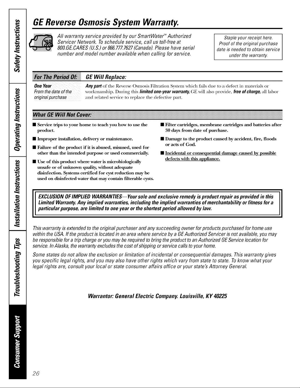
GEReverse OsmosisSystem Warranty.
Aft warranty service provided by our SmartWater TM Authorized
Servicer Network. Toschedule service, call us toll-free at
800.GE.CARES(U.S.) or 866.777.7627(Canada). Please have serial
number and model number available when calling for service.
GE Will Replace:
Anypart of file Reverse Osmosis Filtration System which fidls due to a defect in matedMs or
Fromthe dateofthe
originalpurchase
• Service trips to your home to teach you how to use the
product.
• Improper installation, delivery or maintenance.
• Failure of the product if it is abused, misused, used for
other than the intended purpose or used commercially.
• Use of this product where water is microbiologicaUy
tmsafe or of unknown quality, without adequate
disinfection. Systems certified for cyst reduction may be
used on disinfected water that may contain filterable cysts.
workmanship. During fllis limited one-year warranty, GE Mll Mso provide, free of charge, M1labor
and related service to replace tile defective part.
Staple your receipt here.
Proof of the original purchase
date is needed to obtain service
under the warranty.
• F'flter cartridges, membrane cartridges and batteries after
50 days from date of purchase.
• Damage to the product caused by accident, fire, floods
or acts of God.
• Incidental or consequential damage caused by possible
defects with this appliance.
EXCLUSIONOFIMPLIED WARRANTIES--Your sole and exclusive remedy is product repair as provided in this
Limited Warranty. Any implied warranties, including the implied warranties of merchantability or fitness for a
particular purpose, are limited to one year or the shortest period allowed by law.
This warranty is extended to the original purchaser and any succeeding owner for products purchased for home use
within the USA. If the product is located in an area where service by a GEAuthorized Servicer is not available, you may
be responsible for a trip charge or you may be required to bring the product to an Authorized GEService location for
service. In Alaska, the warranty excludes the cost of shipping or service calls to your home.
Some states do not allow the exclusion or limitation of incidental or consequential damages. This warranty gives
you specific legal rights, and you may also have other rights which vary from state to state. To know what your
legal rights are, consult your local or state consumer affairs office or your state's Attorney General
Warrantor: General Electric Company.Louisville, KY 40225
II
26
 Loading...