

GE PK7000DF Specification
PK7000DF
F
E
22
"
Conduit
40"
8-3/4" MAX.
Cutout depth
23-1/2" MIN
Cabinet 27"
A – Overlap of oven at top of cutout 1"
B – Overlap of oven over side of edges of cutout 1"
C – Overlap of oven at bottom of cutout 1"
Oven
D – Install depth 23-1/2"
E – Overall height with trim 28-7/8"
F – Overall width 26-3/4"
CK7000
PK7000
JK5000
JK3000
JK1000
B
27''
A
C
Cutout width
25" MIN.
25-1/4" MAX.
Recommended
cutout location
from oor
32-1/2"
Cutout height
27-5/8" MIN.
28-1/8" MAX.
23" minimum
door opening
allowance
22" to
bottom of
junction box
Junction box
location
D
F
E
22
"
Conduit
40"
8-3/4"
MAX.
Cutout depth
23-1/2" MIN
B
27''
A
C
Cutout width
25" MIN.
25-1/4" MAX.
Recommended
cutout location
from oor
32-1/2"
Cutout height
27-5/8" MIN.
28-1/8" MAX.
23" minimum
door opening
allowance
22" to
bottom of
junction box
Junction box
location
D
B
27''
A
C
Cutout width
25" MIN.
25-1/4" MAX.
Recommended
cutout location
from oor
32-1/2"
Cutout height
27-5/8" MIN.
28-1/8" MAX.
Cutout depth
23-1/2" MIN
CK7000
PK7000
JK5000
JK3000
JK1000
B
27''
A
C
Cutout width
25" MIN.
25-1/4" MAX.
Recommended
cutout location
from oor
32-1/2"
Cutout height
27-5/8" MIN.
28-1/8" MAX.
22" to
bottom of
junction box
Junction box
location
2-1/2" MIN
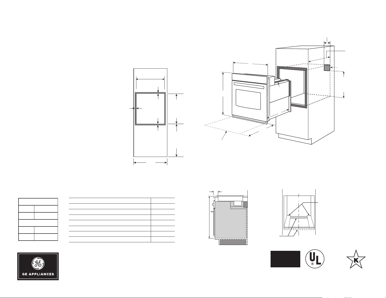
INSTALLATION ABOVE A WALL OVEN
Profile
DIMENSIONS AND INSTALLATION INFORMATION (IN INCHES)
NOTE: These ovens are NOT approved for
stackable or side-by-side installations.
NOTE: Cabinets installed adjacent to wall
ovens must have an adhesion spec of at least a
194°F temperature rating. For 27” built-in single
ovens, if marks, blemishes or the cutout opening
is visible above the installed oven, it may be
necessary to add wood shims under the runners
and front trim until the marks or openings are
covered.
NOTE: Door handle protrudes 3" from door face.
Cabinets and drawers on adjacent 45° and 90°
walls should be placed to avoid interference
with the handle.
Electric wall ovens are not approved for
installation with a plug and receptacle. They
must be hard wired in accordance
with installation instructions.
INSTALLATION I N FORMATI O N :
Before installing, consult installation
instructions packed with product for
current dimensional data.
KW RATING
240V 3.6
208V 2.7
BREAKER SIZE
240V 20 Amps
208V 20 Amps
™
Series 27" Built-In Single Convection Wall Oven
Cabinet 27"
A – Overlap of oven at top of cutout 1"
B – Overlap of oven over side of edges of cutout 1"
C – Overlap of oven at bottom of cutout 1"
Oven
D – Install depth 23-1/2"
E – Overall height with trim 28-7/8"
F – Overall width 26-3/4"
For answers to your Monogram, GE Café™ Series, GE Profile™ Series or
GE Appliances product questions, visit our website at geappliances.com
or call GE Answer Center® Service, 800.626.2000.
PK7000
Dimension and installation information are shown in inches.
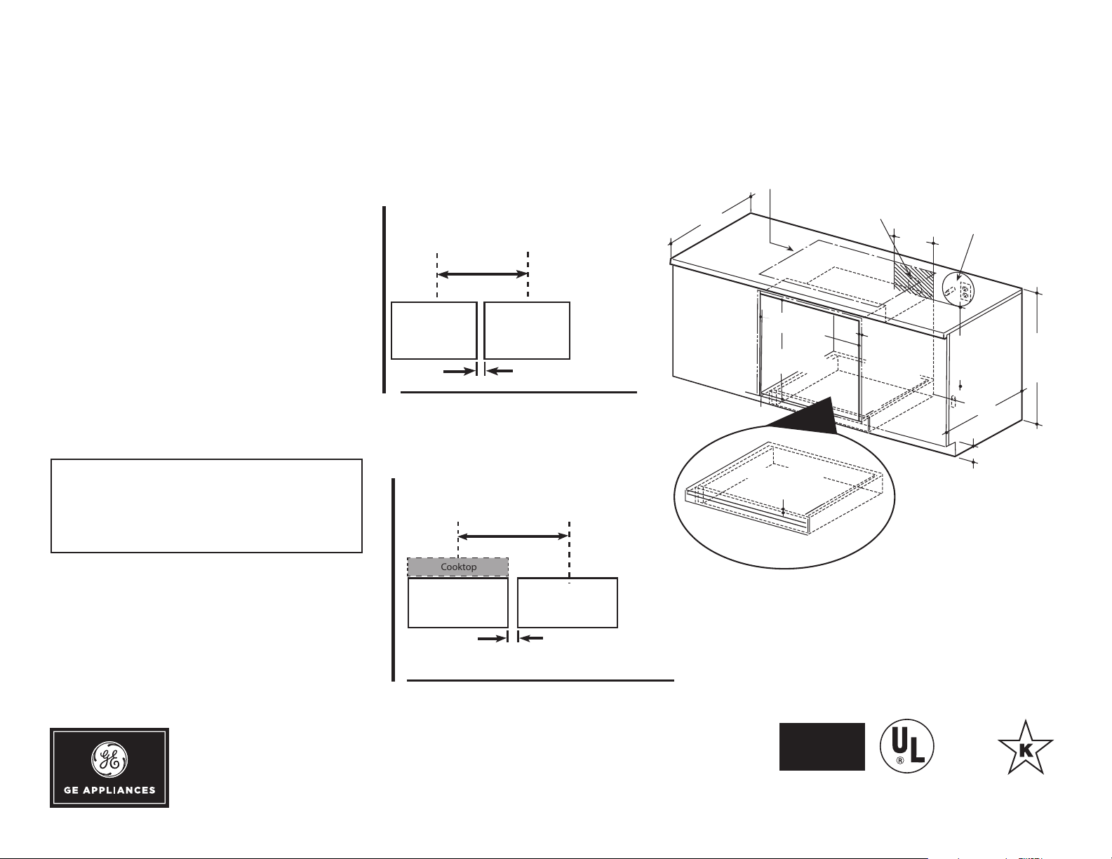
31-1/4" MIN
From top surface
of countertop to
top surface of
wall oven support
platform
From front edge
of countertop to front
edge of cooktop cutout
INSTALLATION BELOW A COOKTOP
Suitable
bracing
to support
runners
COMPLIANT
C
L
(must support 200 lbs.)
ADA
2 x 4 or
equivalent runners
level with bottom of cutout
and ush with sides of cutout
or solid bottom oor.
Listed by
Underwriters
Laboratories
Speci fication Revised 6/18
PK7000DF
25
Gas or electric cooktops may be installed over this
oven. See cooktop installation instructions for cutout size.
See label on top of oven for approved cooktop models.
Gas or electric connections
for gas cooktop must be
located in an adjacent
accessible location to the right
240V / 208V
Junction box
location
36"
Typical
countertop
height
24
4
"
Allow 1"
unit overlap
all edges
25" MIN.
25 1/4" MAX.
8-3/4"
27 5/8" MIN.
28 1/8" MAX.
3/4" Support
platform required
Must Support 200 Lbs.
22" MIN.
Above
support
platform
Side by Side single ovens
Side-by-Side Installations
Install two ovens in separate cutouts.
Center Line
Cutout -
observe all
dimensions and
requirements.
Cutout -
observe all
dimensions and
requirements.
Center Line
30" models
2
" MIN.
27" models
Side by Side single ovens
Side-by-Side Installations
Install two ovens in separate cutouts.
Center Line
Cutout observe all
dimensions and
requirements.
Cutout observe all
dimensions and
requirements.
Center Line
30" models
2
" MIN.
27" models
Side by Side single ovens
Side-by-Side Installations
Install two ovens in separate cutouts.
Center Line
Cutout -
observe all
dimensions and
requirements.
Cutout -
observe all
dimensions and
requirements.
Center Line
30" models
2
" MIN.
27" models
Side by Side single ovens under
cooktop and counter
Side-by-Side Installations
Install two ovens in separate cutouts.
Cooktop
Center LineCenter Line
NOTE: One cooktop may be centered over either oven in
the side-by-side istallation.
Cutout - observe
all dimensions and
requirements.
Cutout - observe
all dimensions and
requirements.
30" models
2
" MIN.
27" models
Profile
UNDERCOUNTER DIMENSIONS AND INSTALLATION INFORMATION
NOTE: 36" ribbon cooktops are approved
for use over GE 30" single wall ovens and
warming drawers. 30" ribbon cooktops are
approved for use over GE 30" and GE 27"
single wall ovens and warming drawers.
Refer to cooktop and wall oven installation
information packed with products for current
dimensional data.
NOTE: Oven is rated for use only under
GE 30" standard or sealed burner gas and
selected GE 30" smoothtop and Calrod®
electric cooktops.
INSTALLATION I N FORMATI O N :
Before installing, consult installation
instructions packed with product for
current dimensional data.
ELECTRIC WALL OVENS ARE NOT
APPROVED FOR INSTALLATION WITH
A PLUG AND RECEPTACLE. THEY
MUST BE HARD WIRED IN ACCORDANCE
WITH INSTALLATION INSTRUCTIONS.
™
Series 27" Built-In Single Convection Wall Oven
SIDE BY SIDE SINGLE OVENS
SIDE BY SIDE SINGLE OVENS UNDER
COOKTOP AND COUNTER
For answers to your Monogram, GE Café™ Series, GE Profile™ Series or
GE Appliances product questions, visit our website at geappliances.com
or call GE Answer Center® Service, 800.626.2000.
Dimension and installation information are shown in inches.
Listed by
ADA
COMPLIANT
Underwriters
Laboratories
Speci fication Revised 6/18
 Loading...