

Page 1
PI-450/950
PIR Camera
Page 2

© 2003 Kalatel, a GE Interlogix company
All Rights Reserved.
Any GE Interlogix, Kalatel division,
software supplied with GE Interlogix,
Kalatel division, products is proprietary and
furnished under license and can be used
or copied only in accordance with the
terms of such license.
This document contains proprietary
information that is protected by copyright.
No part of this document may be
reproduced or transmitted in any form or
by any means without the prior written
permission of GE Interlogix, Kalatel
division.
The information contained in this
document is subject to change without
notice. GE Interlogix, Kalatel division, in
keeping pace with technological advances,
is a company of product innovation.
Therefore, it is difficult to ensure that all
information provided is entirely accurate
and up-to-date. GE Interlogix, Kalatel
division, accepts no responsibility for
inaccuracies or omissions and specifically
disclaims any liabilities, losses, or risks,
personal or otherwise, incurred as a
consequence, directly or indirectly, of the
use or application of any of the contents of
this document.
For the latest product specifications, visit
GE Interlogix, Kalatel division, online at
www.kalatel.com or contact your Kalatel
sales representative.
For technical support before and after installation, call 800-469-1676.
Technical support is available 24 hours a day, 7 days a week.
Call: Tech Support 800-469-1676 (6 A.M. – 5 P.M. PST Monday through Friday)
Tech Support 541-740-3589 (all other times)
Main 800-343-3358 or 541-754-9133
Fax: Tech Support 541-752-9096 (available 24 hours a day)
Main 541-754-7162
Web: www.kalatel.com
1036380B / February 2003
Page 3

Installation Instructions PI-450/950 PIR Camera
BEFORE YOU BEGIN
Read these instructions before installing or operating this product.
Note: This installation should be made by a qualified service person and should conform to
local codes.
This manual provides installation and operation information. To use this
document, you must have the following minimum qualifications:
• A basic knowledge of CCTV systems and components
• A basic knowledge of electrical wiring and low-voltage electrical
hookups
Use this product only for the purpose for which it was designed.
Customer Support
For assistance in installing, operating, maintaining, and troubleshooting
this product, refer to this document and any other documentation
provided. If you still have questions, contact Kalatel Technical Support:
GE Interlogix, Kalatel division
Call: 800-469-1676
Fax: 541-752-9096
Note: You should be at the equipment, ready with details before calling Technical Support.
Conventions Used in this Manual
Boldface or button icons highlight command entries. The following
WARNING, CAUTION, and Note statements identify potential hazards:
* WARNING:
Improper use of this equipment can cause severe bodily injury or
equipment damage.
** CAUTION:
Improper use of this equipment can cause equipment damage.
Note: Notes contain important information about a product or procedure.
* This symbol indicates electrical warnings and cautions.
** This symbol indicates general warnings and cautions.
1036380B / February 2003 3
Page 4
PI-450/950 PIR Camera Installation Instructions
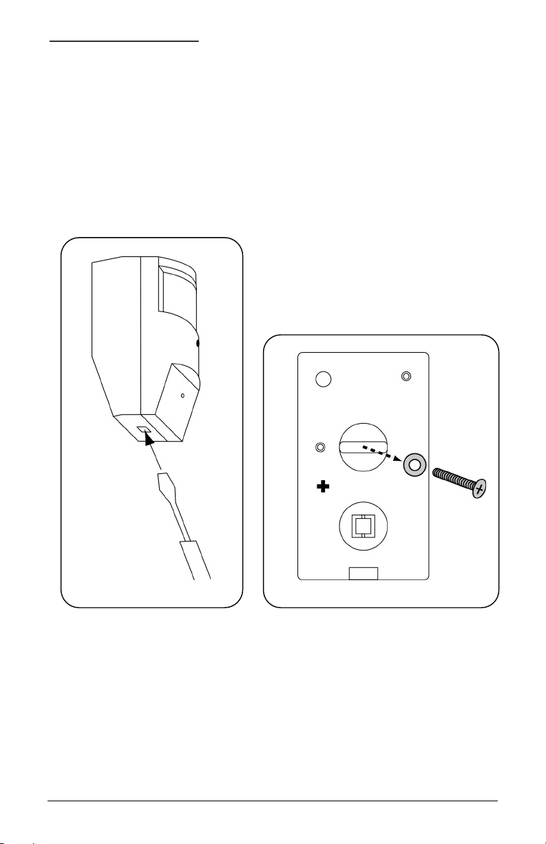
MOUNTING THE UNIT
1) Remove the cover (see Figure 1).
2) Unplug the cable.
3) Detach the wires by loosening the terminal screws.
4) Remove the mounting bracket by removing the screw and washer
(see Figure 2).
Figure 1. Removing the cover Figure 2. Removing the mounting bracket
4 1036380B / February 2003
Page 5

Installation Instructions PI-450/950 PIR Camera
Note: Mount the camera with a 3/8-inch (1 cm) clearance from the ceiling. For optimal PIR
coverage using the standard lens, mount the PIR 7 feet (2 m) above the floor. You may
have to compromise to get good PIR and camera coverage.
5) Mark the mounting holes on the mounting surface (see Figure 3).
Cable hole
for corner
mount
Corner-
mounting
holes
Surface-mounting holes
Figure 3. Mounting bracket
Note: The corner-mounting tabs can be removed for surface mounting.
6) Secure the mounting bracket to the mounting surface using the
provided screws and raw plugs.
1036380B / February 2003 5
Page 6

PI-450/950 PIR Camera Installation Instructions
CONNECTIONS
See Figure 4.
Video Not used
Video ground LED enable/disable jumper
Not used Tamper switch
Not used Tamper
Ground Tamper
12 VDC Normally open
Incoming cable harness Common
Interconnect to camera Normally closed
Figure 4. Circuit board connections
Note: Connections can be made using the supplied cable harness (
terminal strip (
6 1036380B / February 2003
– ).
) or the six-pin
Page 7

Installation Instructions PI-450/950 PIR Camera
LED ENABLE/DISABLE JUMPER
Enabled Disabled
HIGH DENSITY LENS
Figure 5 shows the pattern produced when the PIR is mounted flat
against the wall at a height of 7 feet (2 m). The pattern will vary when the
PIR is angled to get the best camera view.
Figure 5. Pattern produced when the PIR is mounted flat at 7 feet (2 m)
1036380B / February 2003 7
Page 8

PI-450/950 PIR Camera Installation Instructions
CAMERA VIEWS
3/8 in. 54º vertical 18º 69º horizontal
Figure 6. Camera views with a 3.6 mm lens
3/8 in. 36º vertical 18º 48º horizontal
Figure 7. Camera views with a 5 mm lens
8 1036380B / February 2003
Page 9

Installation Instructions PI-450/950 PIR Camera
PIR SPECIFICATIONS
Electrical
Voltage 12 VDC
Current 14 mA typical 20 mA max
Maximum loop rating 16 VDC, 50 mA
Alarm output Failsafe contacts-form C N/C N/O
Alarm duration 3.2 sec (± 0.5 sec)
Cover tamper contacts N/C
Environmental
Operating
temperatures
Humidity 5% to 95% noncondensing
RFI immunity >10 V/m from 10 to 1,000 MHz
Static immunity 20 kV
Lighting immunity 2.4 kV, 1.2 J max energy impulse,
Features
High density lens 35 ft x 90 ft
Mounting Wall or corner
Color White
14 ºF to 122 ºF (-10 ºC to 50 ºC)
100 microsecond duration on field
wiring
1036380B / February 2003 9
Page 10

PI-450/950 PIR Camera Installation Instructions
CAMERA SPECIFICATIONS
PI-450 PI-950
Image sensor 1/3-in. interline transfer
CCD
Lens options 3.6-mm pinhole standard
5-mm pinhole option
Scanning system 2:1 interlace, EIA
525 lines/ 60 fields
option: CCIR 625/50
Sync system Internal Internal
Resolution 425 TV lines 380 TV lines
Sensitivity 0.3 lux @ f1.2 3 lux @ f1.2
AGC Max 30 dB Max 30 dB
S/N ratio 48 dB 48 dB
Electronic shutter 1/60 – 1/100,000 sec 1/60 – 1/100,000 sec
BLC On (under AES), center
weighted
Video output Composite 1 V pk-pk at
75 Ω
Operating
temperature
0 ºF – 140 ºF
(-18 ºC – 60 ºC)
1/3-in. interline transfer
CCD
3.6-mm pinhole standard
5-mm pinhole option
2:1 interlace, NTSC
525 lines / 60 fields
option: PAL 625/50
On (under AES), center
weighted
Composite 1 V pk-pk at
75 Ω
0 ºF – 140 ºF
(-18 ºC – 60 ºC)
Power source 12 VDC 12 VDC
Power consumption 95 mA 120 mA
Weight 1 oz (28 g) 2 oz (60 g)
Size 32 mm x 32 mm 42 mm x 42 mm
10 1036380B / February 2003
Page 11

Page 12

 Loading...