

GE PGSS5PJXCSS, PGSS5PJXBSS, PGSS5NFXBSS, PGSS5NFXASS, PGCS1PJXCSS Owner’s Manual
...
0
ge.com
Safety Instructions ........... 2,3
Operating Instructions
Additional Features ................ 8
Automatic Icemaker ........... 11, 12
Care and Cleaning ............. 12-13
Controls ........................ /4-5
Crispers and Pans .................. 9
Freezer .......................... 10
Replacing the Light Bulbs .......... 1/4
Shelves and Bins ................. 7, 8
Water Filter ........................ 6
Installation Instructions
Installing the Anti-Tip
Floor Bracket .................. 16-17
Installing the Refrigerator ...... 18-22
Installing the Water Line ....... 30-32
Preparing to Install
the Refrigerator ................... 15
Removing and Replacing the
Freezer Drawers ............... 23-26
Removing and Replacing
the Doors (Double Door
Refrigerator Models only) ...... 27-29
Troubleshooting Tips ...... 33-37
Normal Operating Sounds ......... 33
Models 21 ond 2.5Double Freezer Drowers
¢ong_lateur inf_rieur
R frig rateurs
La section frangaise commence 6 la page 47
Congelador inferior
Refrigerodores
La secci6n en espafial empieza en la p6gina 87
--D
Consumer Support
Consumer Support ........ Back Cover
Performance Data Sheet .......... 45
Product Registration
for Canadian Customers ....... 41,/42
Product Registration
for U.S. Customers ............. B9,/40
State of California Water
Treatment Device Certificate ....... /46
Warrantg for Canadian
Customers ....................... 44
Warrantg for U.S.Customers ....... 4B
Write the model and serial
numbers here:
Model #
Serial #
Find these numbers on a label
on the right side, near the top of the
refrigerator compartment.
225D1804PO01
49-60524 !O-07JR
IMPORTANT SAFETY INFORMATION.
READ ALL INSTRUCTIONS BEFORE USING.
WARNING!
Use this appliance only for its intended purpose as described in this Owner's Manual.
SAFETYPRECAUTIONS
When using electrical appliances, basic safetg precautions should be followed, including the following:
?,i:Thisrefrigerator must be properluinstalled
and located in accordance with the Installation
Instructions before it isused.
:¢;_Donot allow childrento climb,stand or hang on the
shelvesin the refrigeratonThey could damage the
refrigerator and seriousluinjurethemselves.
::_¢Donot touch the cold surfaces in the freezer
compartment when hands are damp or wet.
Skinmag stick to these extremelu cold surfaces.
?_:Donot store or usegasoline or other flammable
vapors and liquidsin the vicinity of this or any other
appliance.
:¢;_Keepfingers out of the "pinch point" areas;
clearances between the doors and between the
doors and cabinet are necessarilusmall. Becareful
closing doorswhen children are in the area.
_/i,In refrigerators with automatic icemakers,avoid
contact with the moving parts ofthe ejector
mechanism, or with the heating element that
releasesthe cubes.Do not placefingers or hands
on the automatic icemaking mechanism while
the refrigerator isplugged in.
::i:_;Unplugthe refrigerator before cleaning and making
repairs.
NOTE:Westrongly recommend that any servicing
beperformed by a qualified individual.
_/i,Setting either or both controlsto O(off) does not
remove power to the light circuit.
_: Donot refreezefrozen foods which have
thawed completelu.
DANGER! RISK OF CHILD ENTRAPMENT
PROPERDISPOSAL OF THE REFRIGERATOR
Childentrapment and suffocation are not problems of
the past. Junked or abandoned refrigerators are still
dangerous_.evenif they will sit for 'just a few dags."
If Uouare getting rid of uour old refrigerator, please
follow the instructions belowto help prevent
accidents.
Refrigerants
All refrigeration products contain refrigerants,
which under federal law must be removed prior
to product disposal. If gou are getting rid of an
old refrigeration product, check with the compang
handling the disposal about what to do.
Before You ThrowAway Your Old
Refrigerator or Freezer:
ij_:,Takeoff the doors.
!i_:Leavethe shelves in place sothat children mag not
easiluclimb inside.
USEOF EXTENSION CORDS
Because of potentia! safety hazards under certain conditions, we strongly recommend against
the use of an extension cord.
However,if you must use an extension cord, it is absolutely necessary that it be a UL-listed(inthe United States)
or a CSAcertified (inCanada),3-wire grounding tgpe appliance extension cord having a grounding tgpe plug
and outlet andthat the electrical rating of the cord be 15 amperes (minimum) and 120volts.
WARNING!
HOW TO CONNECT ELECTRICITY
Do not, under any circumstances, cut or remove the third (ground)prong from the power card.
For personal safety, this appliance must be properly grounded.
ge.com
The power cord of this appliance is equipped with
a 3-prong (grounding)plugwhich mates with a
standard 3-prong (grounding)wall outletto
minimize the possibility of electricshock hazard
from this appliance.
Have the wall outlet and circuit checked by a qualified
electrician to make surethe outlet isproperly
grounded.
Where astandard 2-prong wall outlet isencountered,
it is your personal responsibility and obligation to
have it replaced with a propedy grounded 3-prong
wall outlet.
The refrigerator should always be plugged into its
own individual electrical outlet which hasa voltage
rating that matches the rating plate.
Thisprovides the best performance and alsoprevents
overloading house wiring circuits which could cause a
fire hazardfrom overheated wires.
Never unplug your refrigerator by pulling on the
power cord.Always grip plug firmly and pull straight
out from the outlet.
Repairor replaceimmediately all power cords that
have become frayed or otherwise damaged. Do not
use a cord that shows cracks or abrasion damage
along its length or at either end.
When moving the refrigerator away from the wall, be
careful not to rollover or damage the power cord.
READ AND FOLLOW THIS SAFETY INFORMATION
CAREFULLY.
SAVE THESE INSTRUCTIONS
About the controls with temperature settings.
EnerggSover Door Alarm
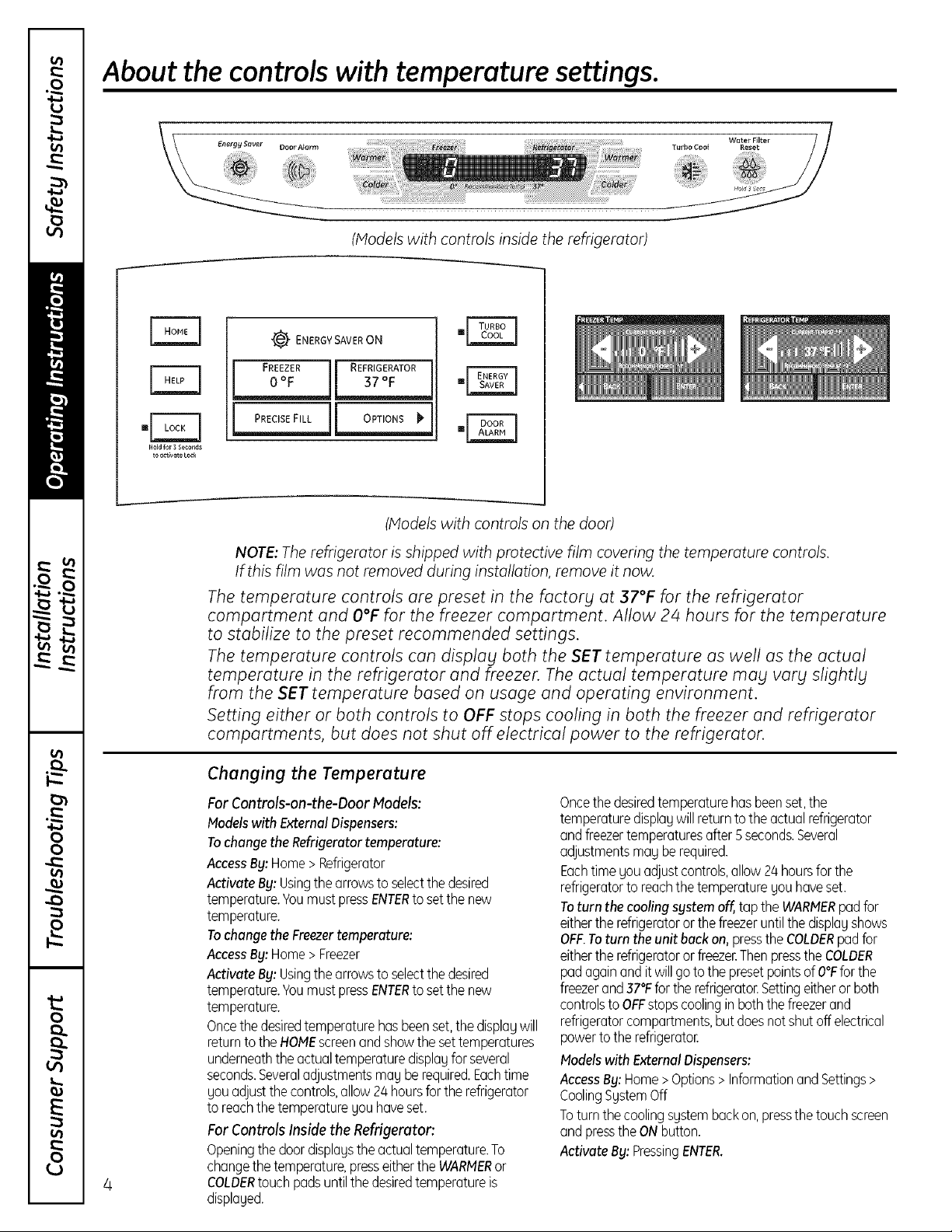
(Models with controls inside the refrigerator)
!_ ENERGYSAVERON
FREEZERJI REFRIGERATOR
°__EL_JL_2LE
Hold for 3 Seconds
to _ctlvate LOCE
(Models with controls on the door)
NOTE: The refrigerator is shipped with protective film covering the temperature controls.
If this film was not removed during installation, remove it now.
The temperature controls are preset in the factory at 37°F for the refrigerator
compartment and O°F for the freezer compartment. Allow 24 hours for the temperature
to stabilize to the preset recommended settings.
The temperature controls can display both the SET temperature as well as the actual
temperature in the refrigerator and freezer. The actual temperature may vary slightly
from the SET temperature based on usage and operating environment.
Setting either or both controls to OFF stops cooling in both the freezer and refrigerator
compartments, but does not shut off electrical power to the refrigerator.
Changing the Temperature
For Controls-on-the-Door Models:
Models with External Dispensers:
To change the Refrigerator temperature:
AccessBy: Home > Refrigerator
Activate By: Usingthe arrows to select the desired
temperature. Youmust pressENTERto setthe new
temperature.
To change the Freezer temperature:
AccessBy: Home > Freezer
Activate By: Usingthe arrows to select the desired
temperature. Youmust pressENTERto setthe new
temperature.
Once the desired temperature has been set,the dispbg will
return to the HOMEscreenand show the set temperatures
underneath the actual temperature display for several
seconds.Severaladjustments may be required.Each time
you adjust the controls, allow 24 hours for the refrigerator
to reach the temperature you have set.
For Controls Inside the Refrigerator:
Opening the door dispbgs the actual temperature. To
change the temperature, presseither the WARMERor
4
COLDERtouch pods until the desiredtemperature is
displayed.
Oncethedesiredtemperaturehasbeenset,the
temperaturedisplaywill returntotheactualrefrigerator
andfreezertemperaturesafter 5seconds.Several
adjustmentsmayberequired.
Eachtime youadjustcontrols,allow24hoursforthe
refrigeratorto reachthetemperatureyou haveset.
Toturn thecooling systemoff,top theWARMERpodfor
eithertherefrigeratororthefreezeruntilthedisplayshows
OFF.Toturn the unitbackon, pressthe COLDERpodfor
eithertherefrigeratororfreezer.ThenpresstheCOLDER
podagainand itwillgotothe presetpointsof O°Fforthe
freezerand37°Ffortherefrigerator.Settingeitheror both
controlsto OFFstopscoolinginboththefreezerand
refrigeratorcompartments,but doesnotshutoffelectrical
powerto therefrigeratoE
Modelswith ExternalDispensers:
AccessBy: Home>Options>InformationandSettings>
CoolingSgstemOff
Toturnthecoolingsystembackon,pressthe touchscreen
andpressthe ONbutton.
ActivateBy:PressingENTER.

About TurboCool.'"Ionsome models) ge.com
How it Works
How to Use
Press TurboCooL The refrigerator
temperature displag willshow bE.
After TurboCool is complete, the
refrigerator compartment willreturn
to the original setting.
NOTES: The refrigerator temperature cannot
be changed during TurboCooL
The freezer temperature is not
affected during TurboCooL
When opening the refrigerator door
during TurboCool, the fans will
continue to run iftheg have
cgcled on,
(on some models)
TURBOco_j
(onsomemodels)
TurboCool rapidly cools the refrigerator
compartment in order to more quickly
coolfoods. UseTurboCool when adding a
large amount of food to the refrigerator
compartment, putting awag foods after theg
have been sitting out at room temperature or
when putting awag warm leftovers. It can
also beusedif the refrigerator hasbeen
without power for an extended period.
Onceactivated, the compressor will turn on
immediately and the fans will cgcle on and
off at high speed as neededfor eight hours.
The compressorwill continue to run until
the refrigerator compartment cools to
approximately 34°F(I°C),then it will cycle
on and off to maintain this setting. After 8
hours,or if TurboCool ispressedagain, the
refrigerator compartment will return to the
original setting.
(on some models)
.i ooo ALARM i
(on some models)
Energg Saver
(on some models)
.[
About Door Alarm (onsome models)
The door alarm will sound if ang door isopen
for morethan 2 minutes.The beeping stops
when gou close the door.
About Energy Saver (onsomemodels)
This product is equipped with an Energg
Saverfeature. The refrigerator isshippedwith
the EnerggSaverfeature enabled.
Overtime, moisture can form onthe front
surface of the refrigerator cabinet and cause
rust. If moisture doesappear on the front
surface of the refrigerator cabinet, turn off
the EnerggSaverfeature bg pressing and
releasingthe ENERGYSAVERpad on the
control panel.
(onsomemodels)
About the water filter. (onsome models)
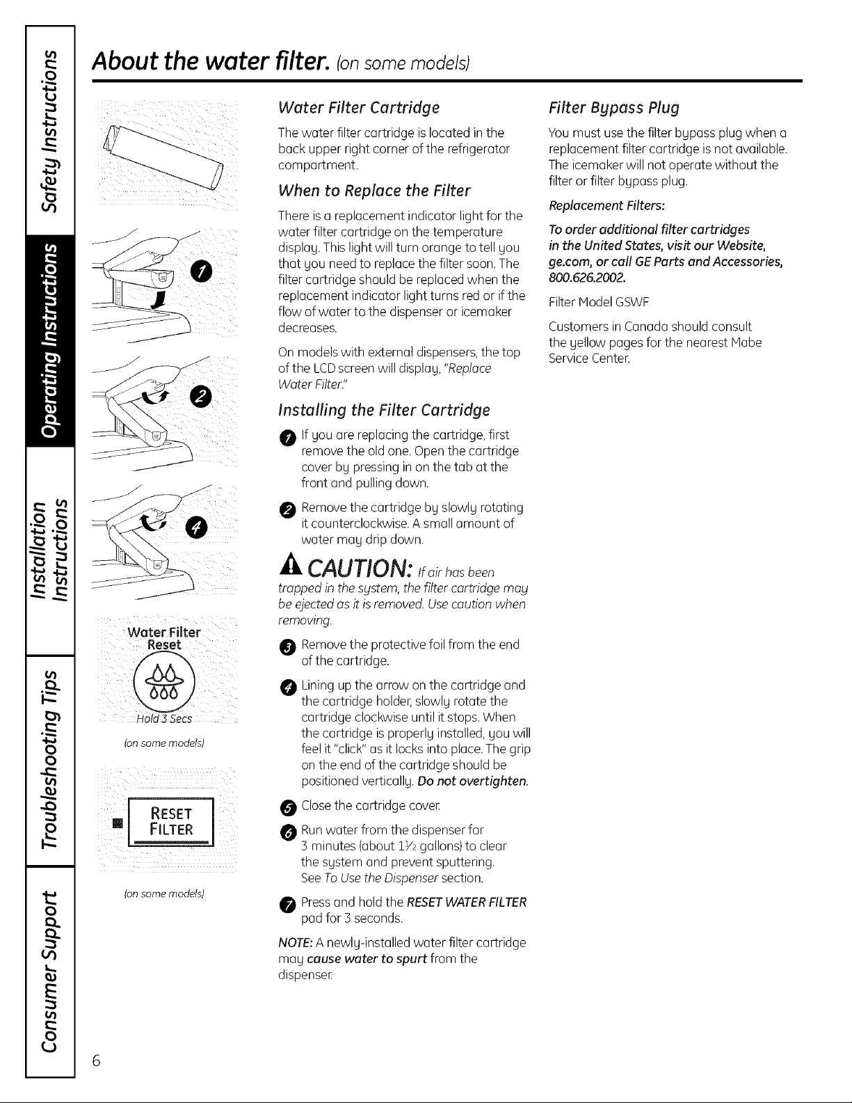
Water Filter Cartridge
Thewater filter cartridge islocated in the
back upper right corner of the refrigerator
compartment.
When to Replace the Filter
Thereis a replacement indicator light for the
water filter cartridge on the temperature
display.Thislight will turn orange to tell you
that you need to replace the filter soon.The
filter cartridge should be replacedwhen the
replacement indicator light turns red or if the
flow of water to the dispenseror icemaker
decreases.
On models with external dispensers, the top
of the LCD screen will display, "Replace
Water Filter."
Installing the Filter Cartridge
O If you are replacingthe cartridge, first
remove the old one. Openthe cartridge
cover bg pressinginon the tab atthe
front and pullingdown.
O Removethe cartridge bg slowlg rotating
it counterclockwise.A small amount of
water may drip down.
Filter Bypass Plug
Youmust usethe filter bgpassplug when a
replacement filter cartridge is not available.
The icemakerwill not operate without the
filter or filter bgpass plug.
Replacement Filters:
Toorder additional filter cartridges
in the United States, visit our Website,
ge.com, or call GEParts and Accessories,
800.626.2002.
Filter Model GSWF
Customersin Canada should consult
the gellow pages for the nearest Mabe
ServiceCenteE
Water Filter
Hold 3 Secs
(on some models)
RESET
FILTER
(on some models)
CAUTION: airhosbeen
trapped in the S_lstem,the filter cartridge may
be ejectedasit is removed.Usecautionwhen
removing.
Removethe protective foilfrom the end
of the cartridge.
Lining upthe arrow on the cartridge and
the cartridge holder,slowlg rotate the
cartridge clockwise until it stops. When
the cartridge isproperlg installed,gouwill
feel it "click"as it locks into place.The grip
on the end of the cartridge should be
positioned verticallg. Do not overtighten.
Closethe cartridge coveE
O Runwater from the dispenserfor
3 minutes (about 1V2gallons)to clear
the sgstem and prevent sputtering.
SeeToUsethe Dispensersection.
Pressand hold the RESETWATERFILTER
pad for 3 seconds.
NOTE:A newlg-installed water filter cartridge
may cause water to spurt from the
dispenseE
6
About the shelves and bins. gecom
Not all features are on all models.
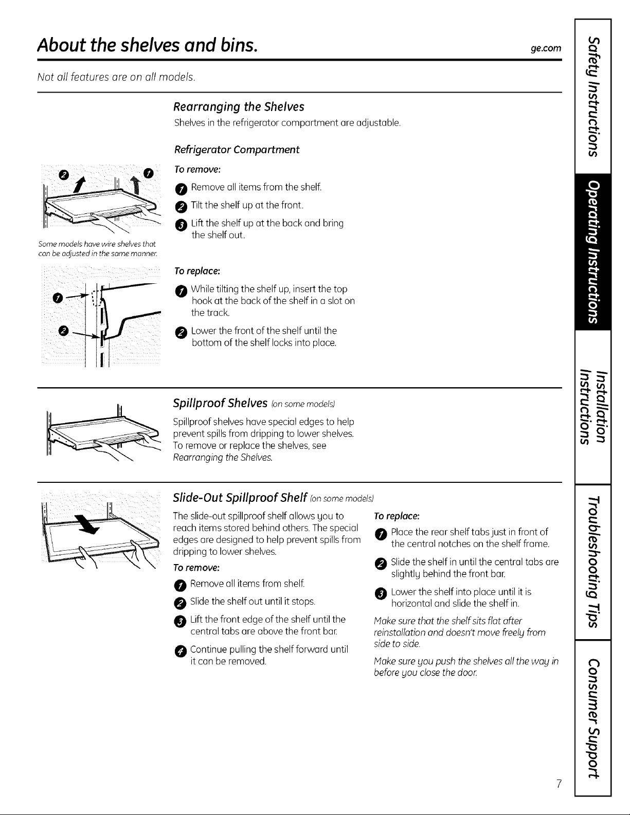
Rearranging the Shelves
Shelvesin the refrigerator compartment are adjustable.
Refrigerator Compartment
Toremove:
0 Removeall itemsfrom the shelf.
0 Tilt the shelf up at the front.
0 Liftthe shelf upat the back and bring
Some modelshave wire shelvesthat
can be adjusted in thesame mannec
the shelf out.
Toreplace:
While tilting the shelf up,insert the top
hook at the back of the shelf in a slot on
the track.
Lowerthe front ofthe shelf until the
bottom of the shelf locksinto place.
i 0
Spillproof Shelves Ionsome models)
Spillproofshelves havespecial edgesto help
prevent spillsfrom dripping to lower shelves.
To removeor replace the shelves,see
Rearrangingthe Shelves.
Slide-Out Spillproof Shelf Ionsome models)
The slide-outspillproof shelf allows Sou to
reach items stored behind others.Thespecial
edgesare designedto help prevent spillsfrom
dripping to lower shelves.
Toremove:
Removeall items from shelf.
Slidethe shelf out until it stops.
Lift thefront edge of the shelf untilthe
central tabs areabove the front bar
Continue pulling the shelf forward until
it can be removed.
Toreplace:
Placethe rear shelftabsjust in front of
the central notches on the shelf frame.
Slidethe shelf in until the central tabs are
slightlg behind the front bat
Lowerthe shelf into place until it is
horizontal and slidethe shelf in.
Hake surethat the shelf sitsflat after
reinstallotionand doesn'tmove freelL]from
sideto side.
Hake sureSoupush theshelvesall the wag in
beforeSou closethe door
About the shelves and bins.
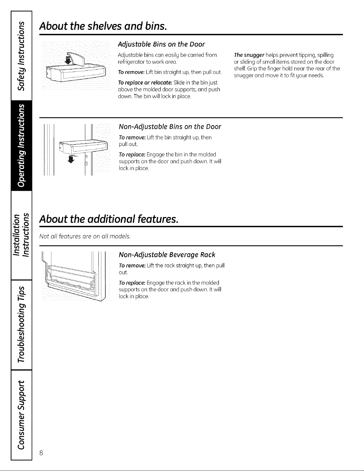
Adjustable Bins on the Door
Adjustable bins can easily be carried from
refrigerator to work area.
Toremove: Lift bin straight up,then pull out.
Toreplace or relocate: Slideinthe binjust
above the molded door supports,and push
down. Thebin will lock in place.
Non-Adjustable Bins on the Door
Toremove: Lift the bin straight up,then
pull out.
Toreplace: Engagethe bin in the molded
supports on the door and push down. It will
lock in place.
About the additional features.
Thesnugger helps prevent tipping, spilling
or slidingof small items stored on the door
shelf.Gripthe finger hold near the rear of the
snugger and move it to fit gour needs.
Not all features are on all models.
Non-Adjustable Beverage Rack
Toremove: Lift the rack straight up, then pull
k
out.
Toreplace: Engagethe rack in the molded
supports on the door and push down. It will
lock in place.
8
About the crispers and pans. ge.com
Not all features are on all models.
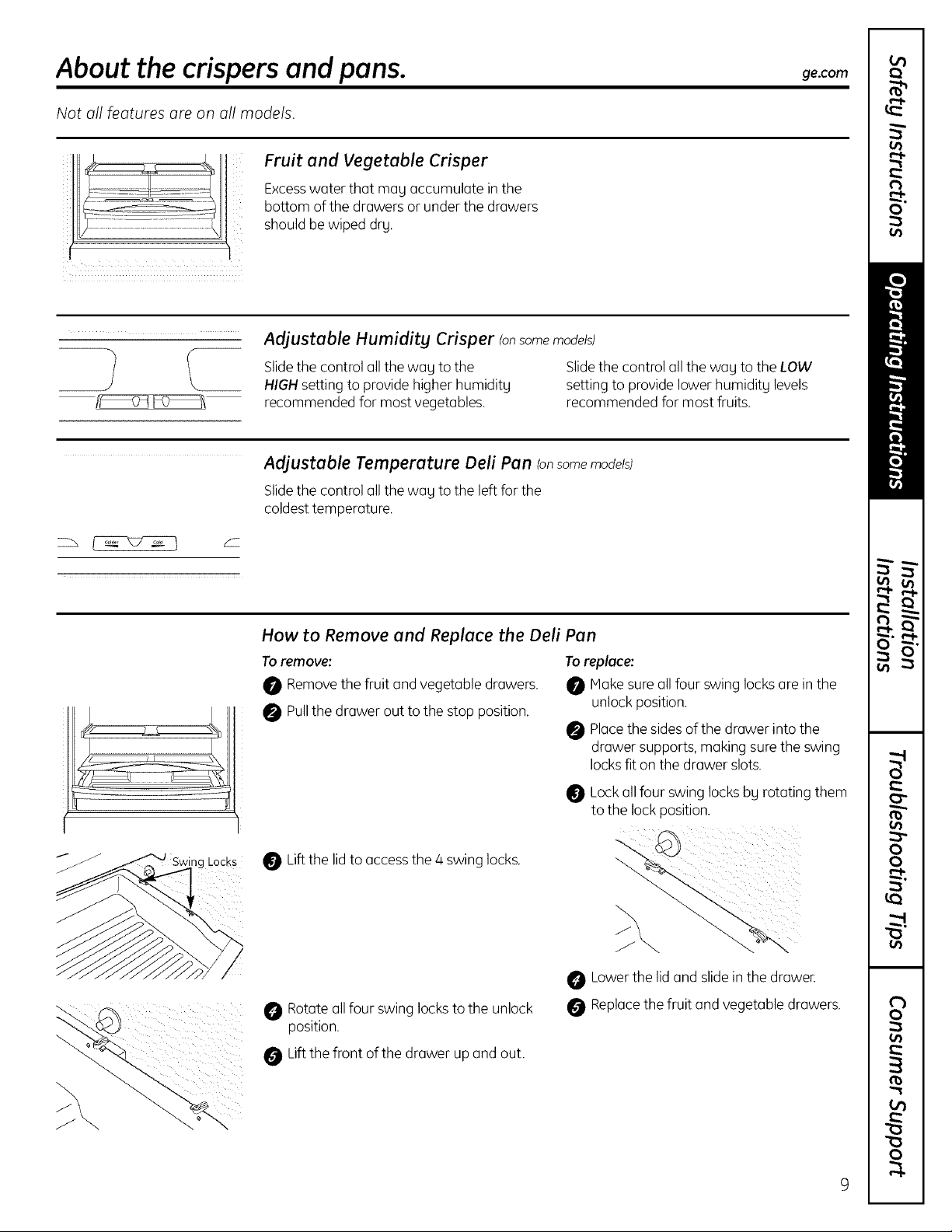
Fruit and Vegetable Crisper
Excesswater that mag accumulate in the
bottom of the drawers or under the drawers
should be wiped dry.
Adjustable Humidity Crisper (onsomemodels)
Slidethe control all the wag to the Slidethe control all the wag to the LOW
HIGHsetting to provide higher humiditg setting to provide lower humiditg levels
recommended for most vegetables, recommended for most fruits.
Adjustable Temperature Dell Pan (onsome models)
Slidethe control all the wag to the left for the
coldesttemperature.
LOCKS
How to Remove and Replace the Dell Pan
Toremove:
0 Remove the fruit and vegetable drawers.
0 Pullthe drawer out to the stop position.
Lift the lid to accessthe 4 swing locks.
Rotateall four swing locksto the unlock
position.
Lift thefront of the drawer up and out.
Toreplace:
Hake sure all four swing locksare in the
unlock position.
Placethe sidesof the drawer into the
drawer supports, making sure the swing
locksfit on the drawer slots.
Lock all four swing locks bg rotating them
to the lockposition.
Lowerthe lid and slidein the drawee
Replacethe fruit and vegetable drawers.
About the freezer.
Not all features are on all models.
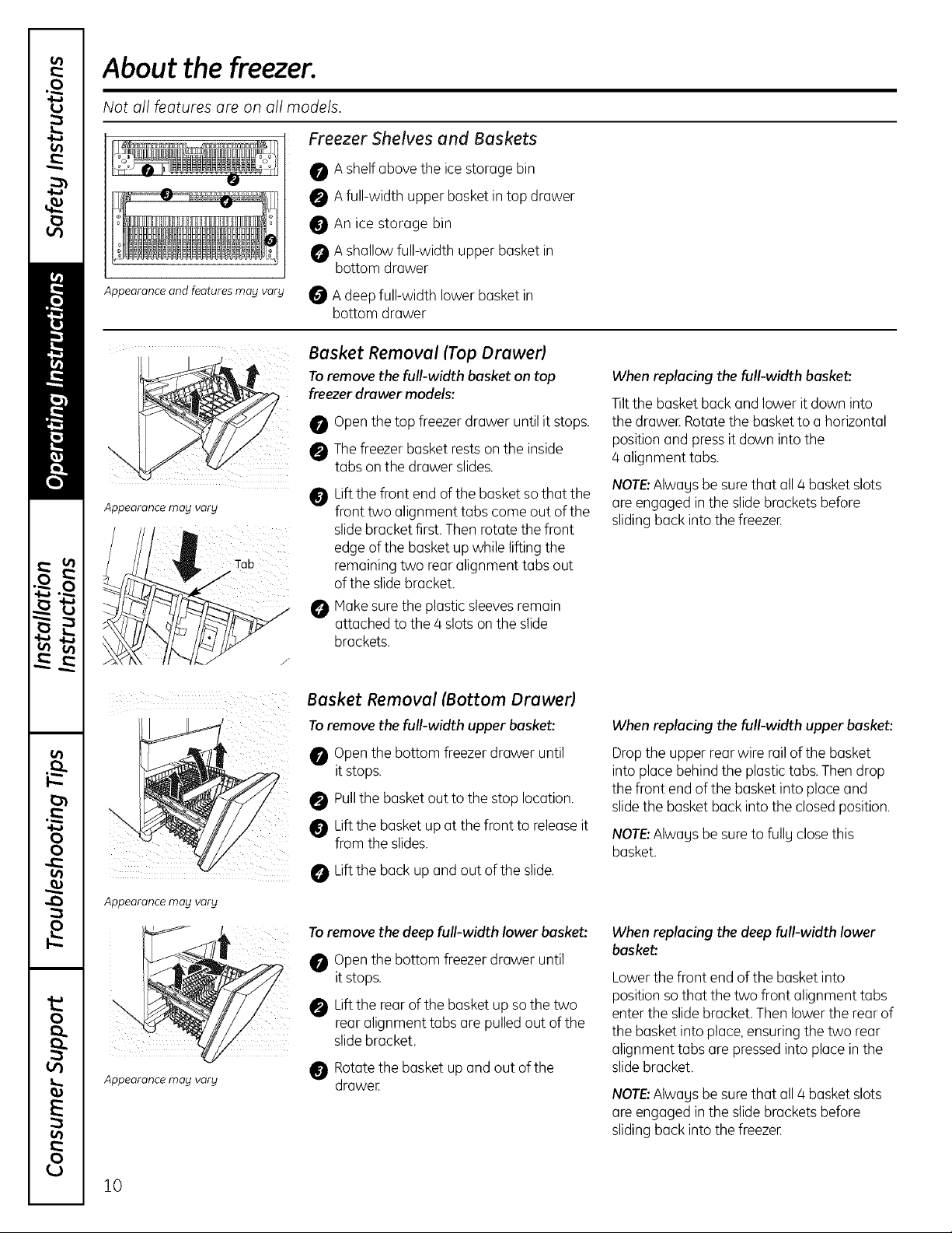
Freezer Shelves and Baskets
0 Ashelf above the ice storage bin
0 Afull-width upper basket in top drawer
Appearance and features may vary
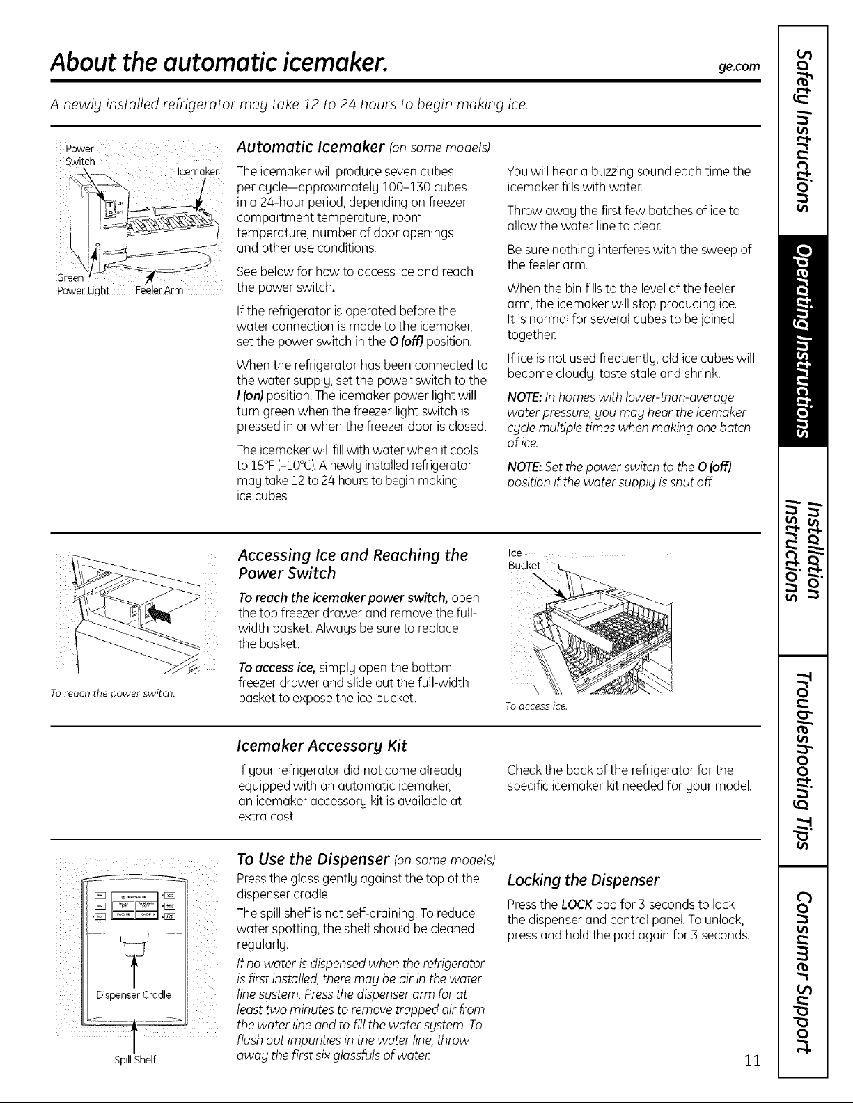
Basket Removal (Top Drawerl
Toremove the full-width basket on top
freezer drawer models:
i
Appearance may vary
An ice storage bin
A shallow full-width upper basket in
bottom drawer
A deep full-width lower basket in
bottom drawer
Openthe top freezer drawer until it stops.
Thefreezer basket rests on the inside
tabs on the drawer slides.
Liftthe front end ofthe basketso that the
front two alignment tabs comeout of the
slidebracket first. Then rotate the front
edge of the basket up while lifting the
remaining two rear alignment tabs out
ofthe slide bracket.
When replacing the full-width basket:
Tiltthe basket back and lower it down into
the drawen Rotate the basketto ahorizontal
position and press it down into the
4 alignment tabs.
NOTE:Alwagsbe sure that all4 basketslots
are engaged in the slidebrackets before
sliding backinto the freezeE
Appearance may varg
Appearance may varg
Make surethe plastic sleevesremain
attached to the 4 slots on the slide
brackets.
Basket Removal (Bottom Orawerl
Toremove the full-width upper basket:
Openthe bottom freezer drawer until
it stops.
Pullthe basket out to the stop location.
Liftthe basket up at the front to releaseit
from the slides.
Liftthe back up and out of the slide.
To remove the deep full-width lower basket:
Openthe bottom freezer drawer until
it stops.
Liftthe rear of the basketup sothe two
rear alignment tabs are pulled out of the
slidebracket.
Rotatethe basket up and out of the
drawee
When replacing the full-width upper basket:
Drop the upper rear wire rail of the basket
into place behind the plastic tabs. Thendrop
the front end of the basket into place and
slidethe basket back into the closed position.
NOTE:Alwagsbe sure to fullg closethis
basket.
When replacing the deep full-width lower
baske_.
Lower the front end of the basket into
position sothat the two front alignment tabs
enter the slide bracket. Then lower the rear of
the basket into place, ensuring the two rear
alignment tabs are pressedinto placein the
slidebracket.
NOTE:Alwagsbe sure that all4 basketslots
are engaged in the slidebrackets before
sliding backinto the freezeE
!0
About the automatic icemaker, ge.com
A newly installed refrigerator may take 12 to 24 hours to begin making ice.
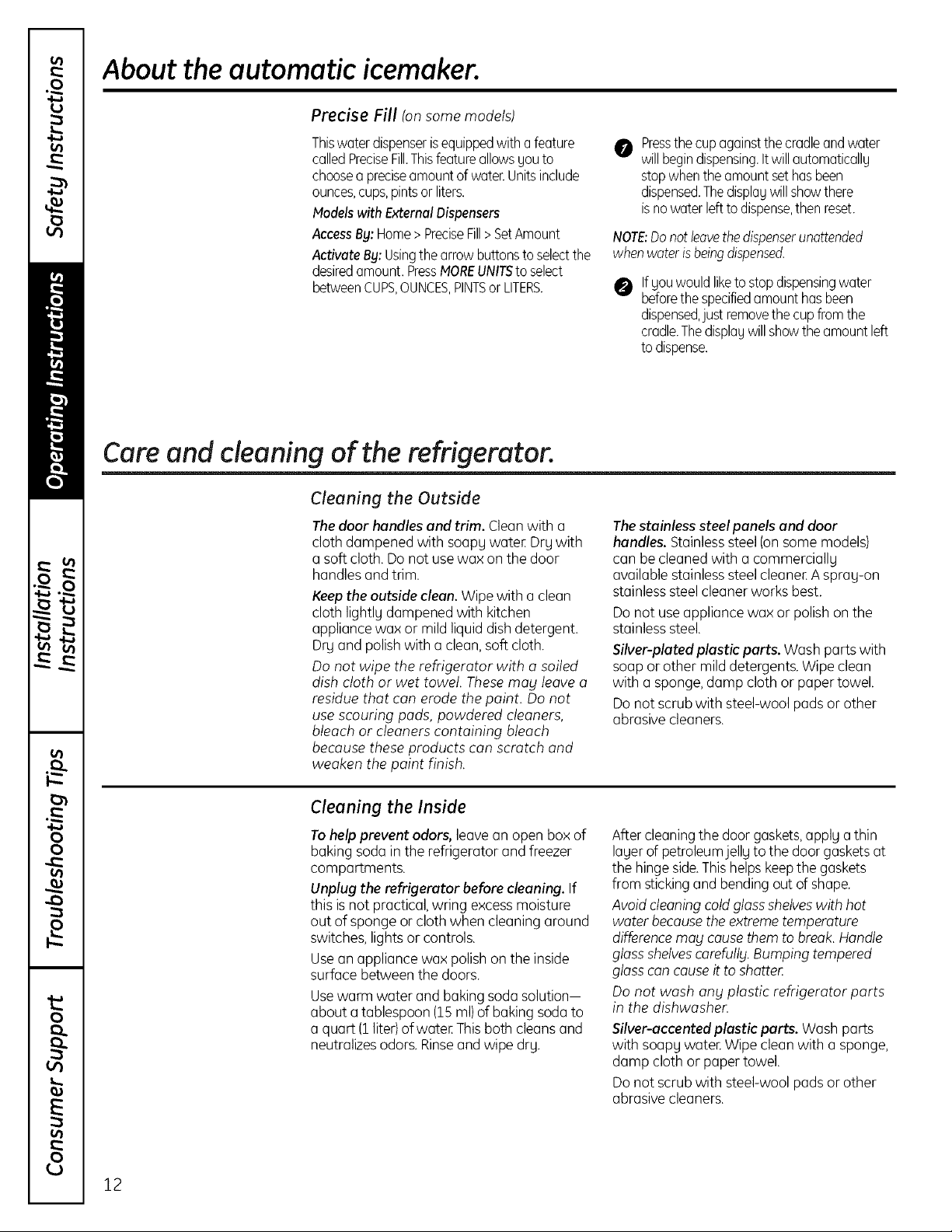
Power Automatic Icemoker tonsomemodels)
Switch
Icemaker
Green
Power Light
Theicemaker will produce sevencubes
per cycle-approximately i00-130cubes
in a 24-hour period,depending on freezer
compartment temperature, room
temperature, number of door openings
and other useconditions.
See below for how to access ice and reach
the power switch.
If the refrigerator is operated before the
water connection is made to the icemaker,
set the power switch in the 0 (of-fl position.
When the refrigerator has been connected to
the water supply, set the power switch to the
/ (on)position.Theicemaker power lightwill
turn green when the freezer light switch is
pressedin or when the freezer door isclosed.
Theicemaker willfillwith water when it cools
to 15°F(-IO°C).A newlyinstalledrefrigerator
may take 12to 24 hours to begin making
icecubes.
You will hear a buzzing sound each time the
icemaker fills with water
Throw away the first few batches of ice to
allow the water line to clear
Besure nothing interferes with the sweepof
the feeler arm.
When the bin fills to the levelof the feeler
arm, the icemakerwill stop producing ice.
It is normal for several cubes to bejoined
together
If ice isnot used frequently, old icecubes will
become cloudy,taste stale and shrink.
NOTE:Inhomes with lower-than-average
water pressure,you may hear the icemaker
cgde multiple timeswhen making one botch
of ice.
NOTE: Set the power switch to the 0 (off}
position if the water supply is shut off
To reach the power switch.
i _ ._ ._
i i i
Dispenser Cradle
SpillShelf
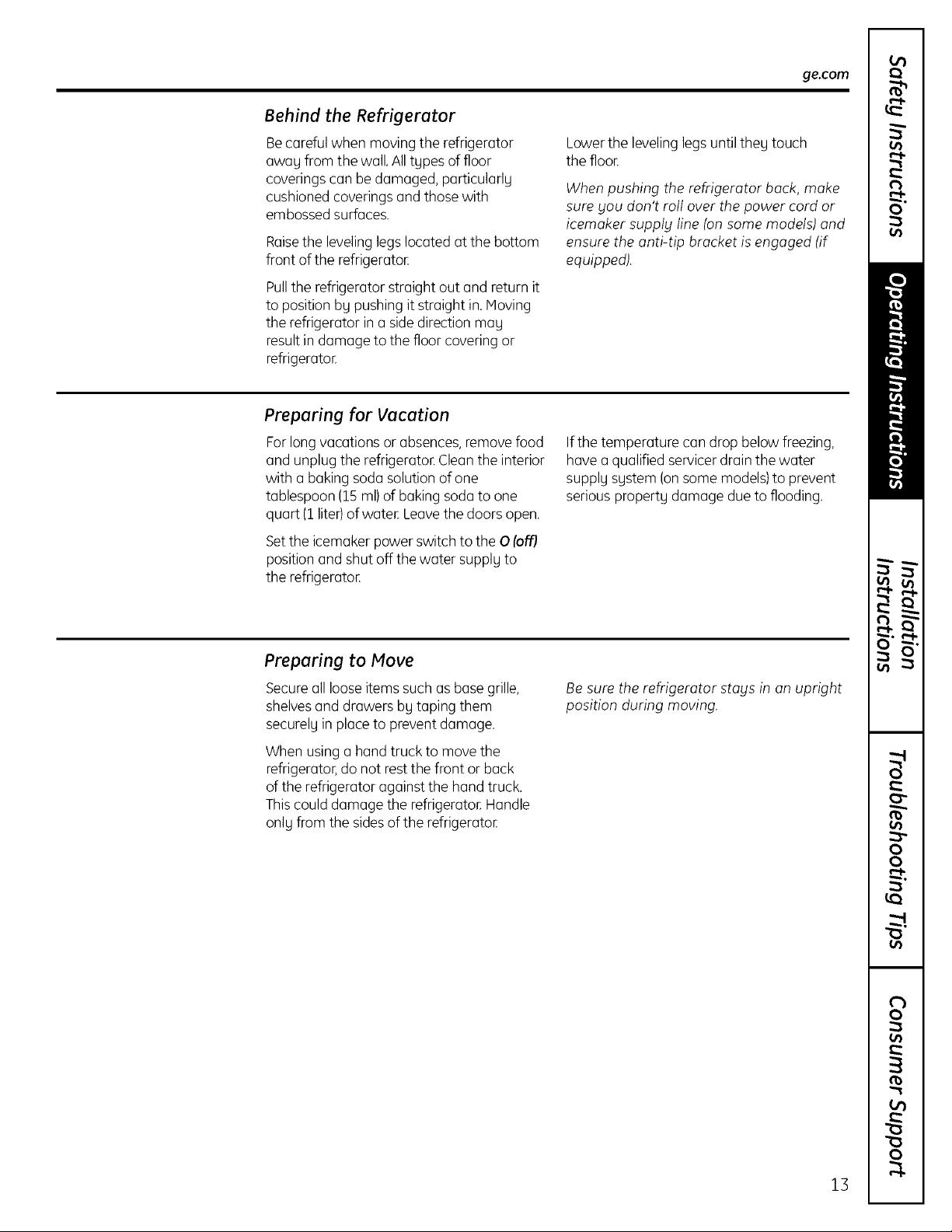
Accessing Iceand Reaching the
Power Switch
Ice
Bucket
To reach the icemaker power switch, open
the top freezer drawer and remove the full-
width basket. Always be sureto replace
the basket.
Toaccess ice, simply open the bottom
freezer drawer and slide out the full-width \
basketto exposethe ice bucket.
To access ice.
Icemaker Accessory Kit
If your refrigerator did not come already
equipped with an automatic icemaker,
an icemakeraccessory kit isavailable at
extra cost.
To Use the Dispenser (onsome models)
Pressthe glass gently against the top of the
dispensercradle.
Thespill shelfis not self-draining.Toreduce
water spotting, the shelf shouldbe cleaned
regularly.
Ifno water is dispensed when the refrigerator
is first installed, there mag be air in the water
line sgstem. Press the dispenser arm for at
least two minutes to remove trapped air from
the water line and to fillthe water sgstem. To
flush out impurities in the water line,throw
awag the first six glassfuls of water
Checkthe back of the refrigerator for the
specific icemaker kit needed for your model.
Locking the Dispenser
Pressthe LOCKpad for 3 seconds to lock
the dispenser and control panel. To unlock,
pressand hold the pad again for 3 seconds.
11
About the automatic icemaker.
Precise Fill ton some models)
Thiswaterdispenserisequippedwitha feature
calledPreciseFill.ThisfeatureallowsUouto
choosea preciseamountof water.Unitsinclude
ounces,cups,pintsorliters.
Modelswith ExternalDispensers
AccessBg:Home>PreciseFill>SetAmount
ActivateBy:Usingthe arrowbuttonsto selectthe
desiredamount PressMOREUNITSto select
betweenCUPS,OUNCES,PINTSor LITERS.
Care and cleaning of the refrigerator.
Cleaning the Outside
Thedoor handles and trim. Cleanwith a
cloth dampened with soapy water Dry with
a soft cloth. Donot use wax on the door
handlesand trim.
Keepthe outside clean.Wipe with a clean
cloth lightlg dampened with kitchen
appliancewax or mild liquid dish detergent.
Dry and polish with a clean, soft cloth.
Do not wipe the refrigerator with o soiled
dish cloth or wet towel. Thesemag leave o
residue that con erode the paint. Do not
use scouring pads, powdered cleaners,
bleach or cleaners containing bleach
because these products can scratch and
weaken the paint finish.
0 Pressthecupagainstthecradleandwater
willbegindispensing.Itwillautomaticallu
stopwhenthe amountsethasbeen
dispensed.Thedisplauwillshowthere
isnowaterleftto dispense,thenreset.
NOTE:Donotleavethedispenserunattended
whenwateris beingdispensed.
If gouwouldliketostopdispensingwater
beforethespecifiedamounthasbeen
dispensed,just removethe cupfromthe
cradle.Thedisplauwillshowthe amountleft
todispense.
Thestainless steel panels and door
handles. Stainlesssteel(onsome models)
can be cleaned with a commerciallg
availablestainless steel cleaner A sprag-on
stainlesssteel cleanerworks best.
Do not use appliance wax or polishon the
stainlesssteel.
Silver-plated plastic parts. Wash parts with
soap or other mild detergents.Wipe clean
with a sponge,damp cloth or papertowel.
Donot scrub with steel-wool padsor other
abrasive cleaners.
12
Cleaning the Inside
Tohelp prevent odors, leavean open box of
baking soda in the refrigerator and freezer
compartments.
Unplug the refrigerator before cleaning.If
this isnot practical,wring excess moisture
out of sponge or cloth when cleaning around
switches, lights or controls.
Usean appliance wax polish on the inside
surface between the doors.
Usewarm water and bakingsoda solution-
about a tablespoon (15ml) of bakingsoda to
a quart (1liter)ofwater. Thisboth cleansand
neutralizesodors. Rinseand wipe drg.
After cleaningthe door gaskets,apply athin
layerof petroleumjelly to the door gasketsat
the hinge side.Thishelpskeep the gaskets
from stickingand bendingout ofshape.
Avoidcleaning coldglossshelveswith hot
water becausethe extreme temperature
differencemag causethem to break.Handle
gloss shelvescorefullg.Bumping tempered
gloss concause it to shotte_
Do not wash ong plastic refrigerator ports
in the dishwasher.
Silver-accented plastic parts. Wash parts
with soapy water Wipe cleonwith o sponge,
damp cloth or papertowel.
Donot scrub with steel-wool podsor other
abrasive cleaners.
Behind the Refrigerator
Becareful when moving the refrigerator
uwoy from the woe All tgpes of floor
coveringscon be dumuged, porticulorlu
cushioned coverings ond those with
embossedsurfaces.
Roisethe leveling legs located at the bottom
front of the refrigeroton
Pullthe refrigerotor stroight out ond return it
to position bg pushing it struight in.Moving
the refrigerutor in o sidedirection mug
result in dumuge to the floor covering or
refrigeruton
Preparing for Vacation
Forlong vocations or obsences,remove food
and unplug the refrigeroto_ Cleonthe interior
with o boking sodu solution of one
tublespoon (15ml)of boking sodu to one
quart (1liter)of woten Leave the doors open.
Setthe icemuker power switch to the 0 (off)
position und shut off the water supplu to
the refrigeroton
ge.com
Lowerthe leveling legsuntil they touch
the floon
When pushing the refrigerator buck, make
sure you don't roll over the power cord or
icemuker supply line (on some models) and
ensure the unti-tip bracket is engaged (if
equipped).
If the temperoture con drop below freezing,
hove o quulified servicer droin the woter
supply system {onsome models)to prevent
serious property dumuge due to flooding.
Preparing to Move
Secureoil looseitems such as bose grille,
shelvesond drowers by toping them
securely inplaceto prevent domoge.
When using o bond truck to move the
refrigerotor,do not rest the front or buck
of the refrigerotor ogoinst the bond truck.
This could domoge the refrigerotor.Hondle
only from the sidesof the refrigerotoE
Be sure the refrigerator stays in on upright
position during moving.
13
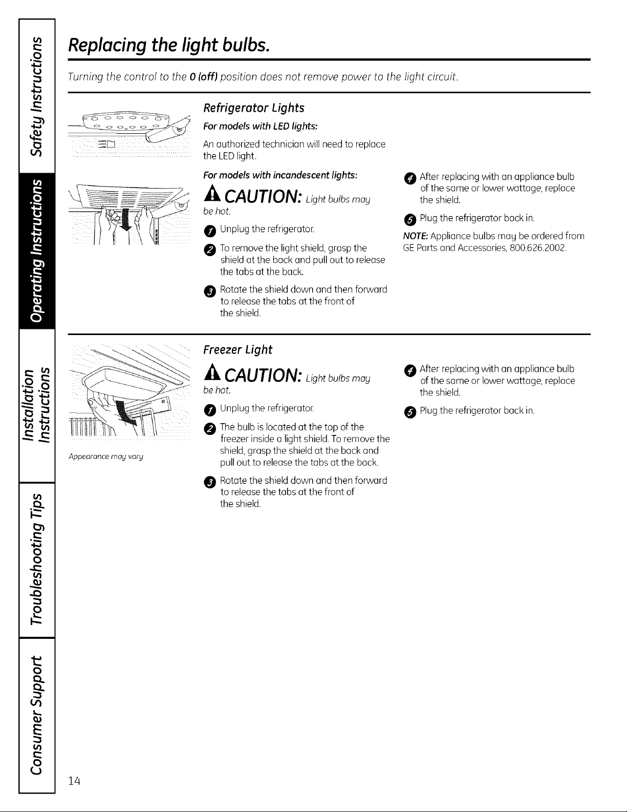
Replacingthe light bulbs.
Turning the control to the 0 (off) position does not remove power to the light circuit.
Refrigerator Lights
Formodels with LEDlights:
An authorized technician will needto replace
the LEDlight.
Appearance may varg
Formodels with incandescent lights:
CAUTION:Light bulbs may
be hot,
0 Unplug the refrigerator.
0 To remove the light shield, grasp the
shield at the back and pull out to release
the tabs at the back.
Rotatethe shielddown and then forward
to releasethe tabs at the front of
the shield.
Freezer Light
CAUTION:Light bulbs may
be hot,
Unplug the refrigerator.
Thebulb islocated at the top of the
freezer insidea light shield.Toremove the
shield,grasp the shield at the back and
pull out to releasethe tabs at the back.
Rotatethe shielddown and then forward
@
to releasethe tabs at the front of
the shield.
After replacing with an appliance bulb
of the same or lower wattage, replace
the shield,
Plug the refrigerator back in.
NOTE: Appliance bulbs may be ordered from
GE Parts and Accessories, 800.626.2002.
After replacing with an appliance bulb
of the same or lower wattage, replace
the shield,
Plugthe refrigerator back in.
!4
Installation
Refrigerator
Instructions
Questions? Call 800.GE.CARES (800.432.2737) or Visit our Website at: ge.com
I
BEFORE YOU BEGIN
Read these instructions completely and carefully.
• INPORTANT- Savetheseinstructionsforlocal
inspector's use.
• IMPORTANT- Observeallgoverning codes and
ordinances.
• Note to Installer- Besure to leavethese instructionswith
the Consumer.
• Note to Consumer- Keepthese instructionsfor future
reference.
• Skilllevel - Installation of this appliance requiresbasic
mechanical skills.
In Canada, call 1.800.561.3344 or Visit our Website at: www.geappliances.ca
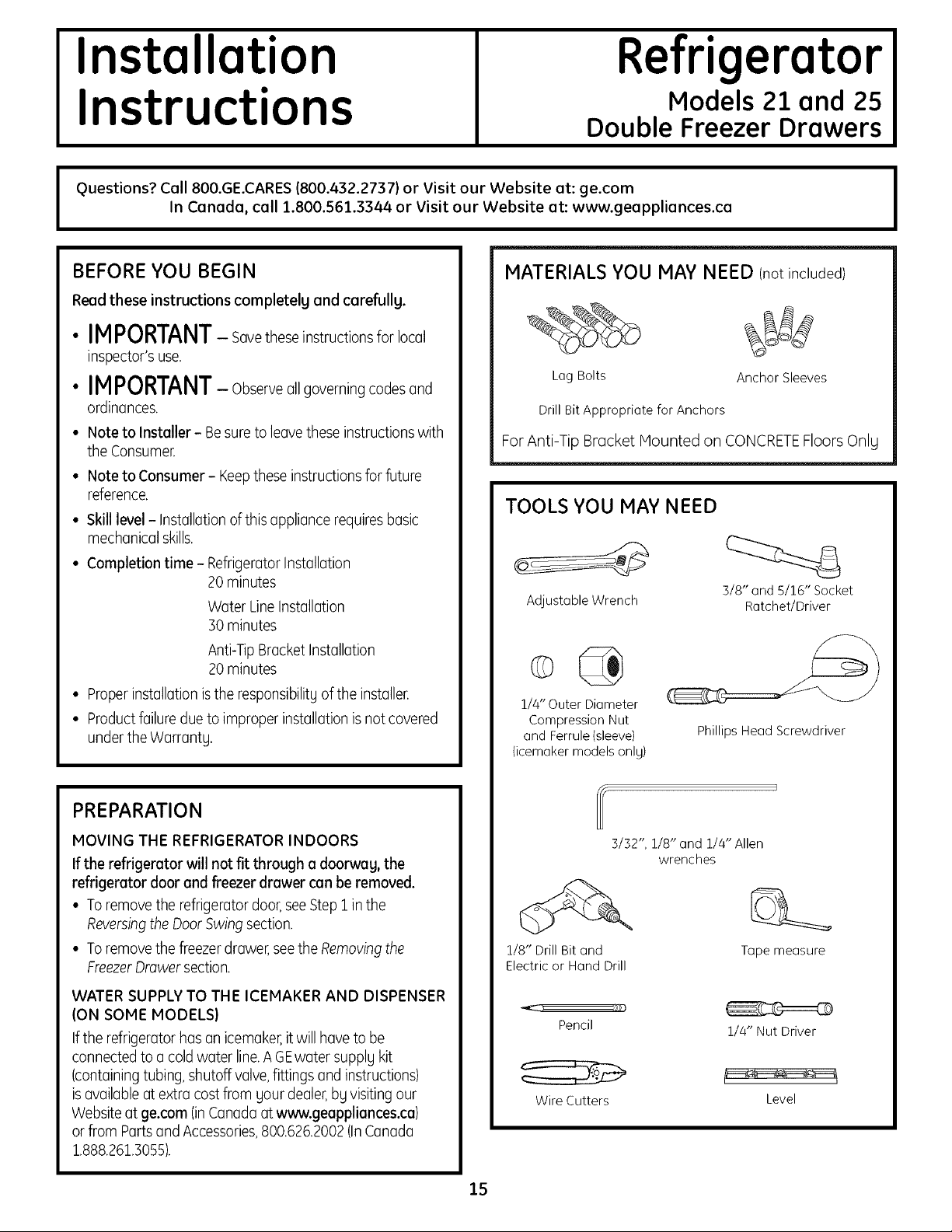
MATERIALS YOU MAY NEED (not included)
Lag Bolts
Drill Bit Appropriate for Anchors
ForAnti-Tip Bracket Mounted on CONCRETEFloors Onlu
TOOLS YOU MAY NEED
Models 21 and 25
Double Freezer Drawers
I
Anchor Sleeves
• Completion time- RefrigeratorInstallation
20 minutes
Water Line Installation
30 minutes
Anti-Tip Bracket Installation
20 minutes
• Properinstallation is the responsibilitUof the installer.
• Productfailure due to improper installation is notcovered
under the Warrantg,
PREPARATION
MOVING THE REFRIGERATOR INDOORS
If the refrigerator will not fit through a doorwag, the
refrigerator door and freezer drawer can be removed.
• To remove the refrigerator door,see Step1 in the
Reversingthe DoorSwing section.
• To remove the freezerdrawer,see the Removingthe
FreezerDrawer section.
WATER SUPPLYTO THE ICEMAKER AND DISPENSER
(ON SOME MODELS)
If the refrigerator has an icemaker,it will have to be
connected to a coldwater line.A GEwater supply kit
(containing tubing, shutoff valve,fittings and instructions)
isavailable at extra cost from your dealer,bg visiting our
Websiteat ge.com (inCanadaat www.geappliances.ca)
or from PartsandAccessories,800.626.2002(InCanada
1,888,261,3055),
Adjustable Wrench
i/4"Outer Diameter
Compression Nut
and Ferrule {sleeve)
(icemaker models only)
3/32", 1/8" and 1/4" Allen
1/8" Drill Bit and
Electric or Hand Drill
J ,,})Y)
Pencil
Wire Cutters
3/8" and 5/16" Socket
Ratchet/Driver
Phillips Head Screwdriver
wrenches
Tapemeasure
1/4" Nut Driver
Level
15
Installation Instructions
INSTALLING THE ANTI-TIP FLOOR BRACKET(on 21 ft. models)
A'kWARNING
N
Under certain circumstances, this refrigerator
can tip forward.
Injury to persons can result.
Install Anti-Tip Bracket packed with this
refrigerator.
[] MEASURE CABINET OPENING
AVAILABLE VS. REFRIGERATOR WIDTH
Measure width of cabinet opening where
refrigerator will be placed, W.
Be sure to account for any countertop
overhang, baseboard thickness and any
clearance desired. Width, W, should not be less
than 36 inches. The refrigerator will be placed
approximatelg in the middle of this opening.
Baseboard
Rear Wall
I
' W
I
14
l REFRIGERATOR
Front
"_' Is Greater) Plus
_I I_" Overhang
Thickness
or Countertop
, (Whichever
Ang Desired
Clearance
RH Side
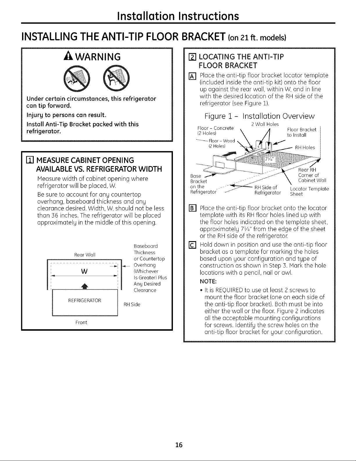
[] LOCATING THE ANTI-TIP
FLOOR BRACKET
Place the anti-tip floor bracket Iocator template
[]
(included inside the anti-tip kit) onto the floor
up against the rear wall, within W, and in line
with the desired location of the RH side of the
refrigerator (see Figure !).
Figure 1 - Installation Overview
2 Wall Holes
Bracket
on the .-o-"_ RHSide of Locator Template
Refrigerator _ Refrigerator Sheet
[] Place the anti-tip floor bracket onto the Iocator
template with its RH floor holes lined up with
the floor holes indicated on the template sheet,
approximately 7W' from the edge of the sheet
or the RH side of the refrigerator.
[] Hold down in position and use the anti-tip floor
bracket as a template for marking the holes
based upon your configuration and type of
construction as shown in Step 3. Mark the hole
locations with a pencil, nail or awl.
NOTE:
• It is REQUIREDto use at least 2 screws to
mount the floor bracket (one on each side of
the anti-tip floor bracket). Both must be into
either the wall or the floor. Figure 2 indicates
all the acceptable mounting configurations
for screws. Identify the screw holes on the
anti-tip floor bracket for your configuration.
16
instatlation instructions
[] LOCATING THE ANTI-TIP
FLOOR BRACKET (cont.)
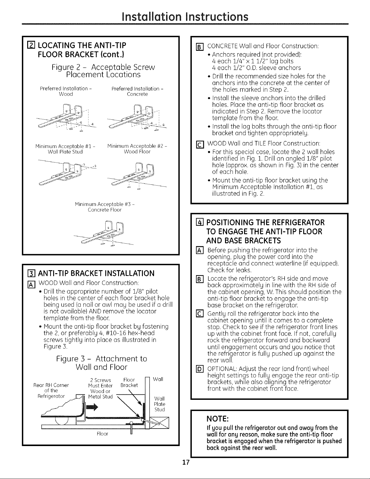
Figure 2 - Acceptable Screw
Placement Locations
Preferred Installation - Preferred Installation -
Minimum Acceptable #1 -
Wood Concrete
i i
i
Minimum Acceptable #2 -
Wall Plate Stud
Minimum Acceptable #3 -
Concrete Floor
Wood Floor
i i
[] CONCRETEWall and Floor Construction:
• Anchors required (not provided):
4 each 1/4" x 1 1/2" lag bolts
4 each 1/2" O.D. sleeve anchors
• Drill the recommended size holes for the
anchors into the concrete at the center of
the holes marked in Step 2.
• Install the sleeve anchors into the drilled
holes. Place the anti-tip floor bracket as
indicated in Step 2. Remove the Iocator
template from the floor.
• Install the lag bolts through the anti-tip floor
bracket and tighten appropriately.
[] WOOD Wall and TILE Floor Construction:
• For this special case, locate the 2 wall holes
identified in Fig. 1. Drill an angled 1/8" pilot
hole (approx. as shown in Fig. 3)in the center
of each hole.
• Mount the anti-tip floor bracket using the
Minimum Acceptable Installation #1, as
illustrated in Fig. 2.
[] ANTI-TIP BRACKET INSTALLATION
[] WOOD Wall and Floor Construction:
• Drill the appropriate number of 1/8" pilot
holes in the center of each floor bracket hole
being used (a nail or awl may be used if a drill
is not available) AND remove the Iocator
template from the floor.
• Mount the anti-tip floor bracket by fastening
the 2, or preferably 4, #10-16 hex-head
screws tightly into place as illustrated in
Figure 3.
Figure 3 - Attachment to
Wall and Floor
2 Screws Floor ["1 Wall
Rear RH Corner Must Enter Bracket I I
of the Wood or \ I I
Refrigerator _ Metal Stud _ N, H Wall
[] POSITIONING THE REFRIGERATOR
TO ENGAGE THE ANTI-TIP FLOOR
AND BASE BRACKETS
[] Before pushing the refrigerator into the
opening, plug the power cord into the
receptacle and connect waterline (if equipped).
Check for leaks.
[] Locate the refrigerator's RH side and move
back approximately in line with the RH side of
the cabinet opening, W. This should position the
anti-tip floor bracket to engage the anti-tip
base bracket on the refrigerator.
[] Gently roll the refrigerator back into the
cabinet opening until it comes to a complete
stop. Check to see if the refrigerator front lines
up with the cabinet front face. If not, carefully
rock the refrigerator forward and backward
until engagement occurs and you notice that
the refrigerator is fully pushed up against the
rear wall.
[] OPTIONAL: Adjust the rear (and front) wheel
height settings to fully engage the rear anti-tip
brackets, while also aligning the refrigerator
front with the cabinet front face.
17
NOTE:
If you pull the refrigerator out and away from the
wall for any reason, muke sure the unti-tip floor
brucket is enguged when the refrigerutor is pushed
buck uguinst the reur wull.
Installation Instructions
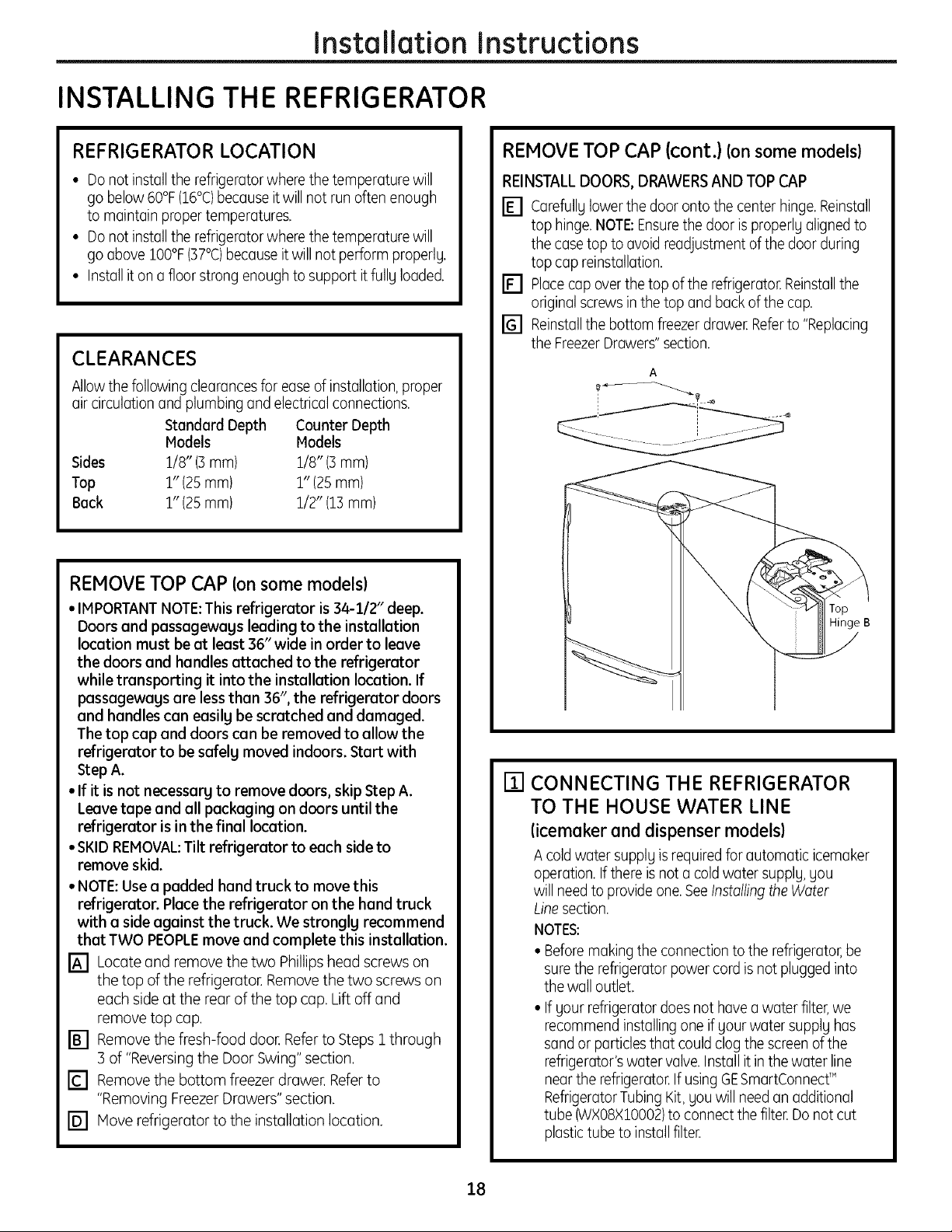
INSTALLING THE REFRIGERATOR
REFRIGERATOR LOCATION
• Do not install the refrigerator where the temperature will
go below 60°F(16°C)because it will not run often enough
to maintain proper temperatures.
• Do not install the refrigerator where the temperature will
go above IO0°F(37°C)because itwill not perform properlg.
• Installit on a floor strong enoughto support it fullg loaded.
CLEARANCES
Allowthe following clearancesfor easeofinstallation, proper
air circulationand plumbing and electricalconnections.
Standard Depth Counter Depth
Models Models
Sides 1/8" (3 mm) 1/8" (3 mm)
Top 1" (25mm) 1" (25mm)
Back 1" (25mm) 1/2" (13mm)
REMOVE TOP CAP (on some models)
• IMPORTANTNOTE:This refrigerator is 34-1/2" deep.
Doors and passagewags leading to the installation
location must be at least 36" wide in order to leave
the doors and handles attached to the refrigerator
while transporting it into the installation location. If
passagewags ore less than 36", the refrigerator doors
and handles con easilg be scratched and damaged.
The top cop and doors con be removed to allow the
refrigerator to be safelg moved indoors. Start with
Step A.
• If it is not necessarg to remove doors, skip Step A.
Leave tape and all packaging on doors until the
refrigerator is in the final location.
• SKIDREMOVAL:Tilt refrigerator to each side to
remove skid.
• NOTE:Usea podded hand truck to move this
refrigerator. Place the refrigerator on the hand truck
with a side against the truck. We stronglg recommend
that TWO PEOPLEmove and complete this installation.
[] Locate and remove the two Phillipshead screws on
the top of the refrigerator. Remove the two screws on
each side at the rear of the top cap. Lift off and
remove top cap.
[] Remove the fresh-food door. Refer to Steps 1 through
3 of "Reversing the Door Swing" section.
[] Remove the bottom freezer drawer. Referto
"Removing FreezerDrawers" section.
[] Move refrigerator to the installation location.
REMOVE TOP CAP (cont.} (on some models)
REINSTALLDOORS, DRAWERSAND TOPCAP
[] Carefullg lowerthe door onto the center hinge.Reinstall
top hinge.NOTE:Ensurethe door is properlg aligned to
the case top to avoid readjustment of the door during
top cap reinstallation.
[] Placecap overthe top of the refrigerator. Reinstallthe
original screwsin the top and back of the cap.
[] Reinstallthe bottom freezer drawer.Referto "Replacing
the FreezerDrawers"section.
Top
Hinge B
[] CONNECTING THE REFRIGERATOR
TO THE HOUSE WATER LINE
licemaker and dispenser models)
A coldwater supplgis required for automatic icemoker
operation. If there isnot a coldwater supplg,gou
will needto provide one.SeeInstallingthe Water
Linesection.
NOTES:
• Beforemaking the connectionto the refrigerator, be
surethe refrigerator power cord is notplugged into
the wall outlet.
• If gour refrigerator does not havea water filter,we
recommend installing one if gour water supplg has
sandor particlesthat couldclog the screen of the
refrigerator'swater valve. Installitin the water line
near the refrigerator.If usingGESmartConnectT'
RefrigeratorTubing Kit, gou will need an additional
tube (WXO8XIO002)to connect the filter.Do not cut
plastictube to installfilter.
18
Installation Instructions
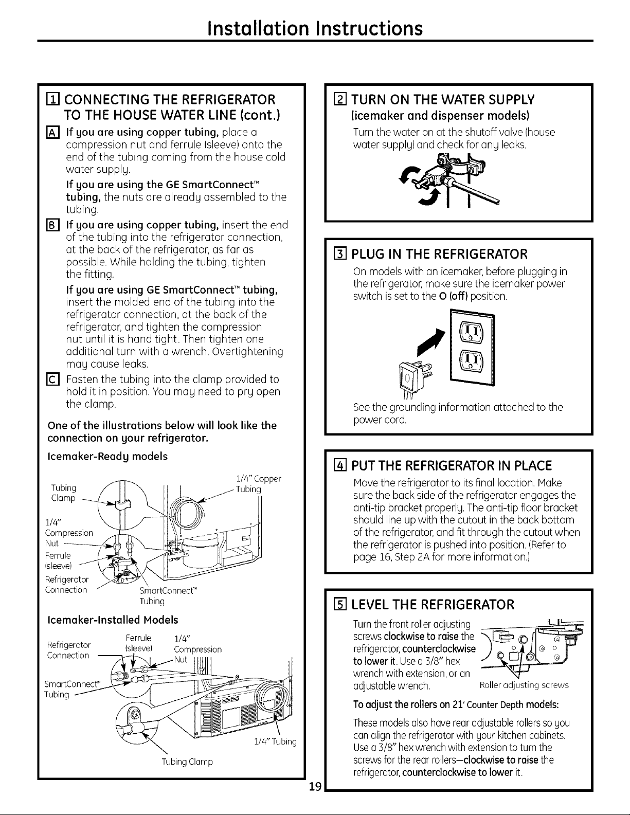
[] CONNECTING THE REFRIGERATOR
TO THE HOUSE WATER LINE (cont.)
[] If you ore using copper tubing, place a
compression nut and ferrule (sleeve) onto the
end of the tubing coming from the house cold
water supply.
If you are using the GE SmartConnect"
tubing, the nuts are already assembled to the
tubing.
[] If you are using copper tubing, insert the end
of the tubing into the refrigerator connection,
at the back of the refrigerator, as far as
possible. While holding the tubing, tighten
the fitting.
If you ore using GE SmortConnect TM tubing,
insert the molded end of the tubing into the
refrigerator connection, at the back of the
refrigerator, and tighten the compression
nut until it is hand tight. Then tighten one
additional turn with a wrench. Overtightening
may cause leaks.
[] Fasten the tubing into the clamp provided to
hold it in position. You may need to pry open
the clamp.
One of the illustrations below will look like the
connection on your refrigerator.
[] TURN ON THE WATER SUPPLY
(icemoker end dispenser models)
Turn the water on at the shutoff valve (house
water supply) and check for any leaks.
[] PLUG IN THE REFRIGERATOR
On models with an icemaker, before plugging in
the refrigerator, make sure the icemaker power
switch is set to the 0 (off) position.
See the grounding information attached to the
power cord.
Icemoker-Reodg models
Tubing
Clamp
1/4"
Compression
Nut
Ferrule
(sleeve)
Refrigerator
Connection SmartConnecf"
Tubing
Icemoker-lnstolled Models
Refrigerator
Connection
SmartConnect"
Tubing
Ferrule
(sleeve)
1/4"
Compression
TubingClamp
1/4"Copper
1/4" Tubing
[] PUT THE REFRIGERATOR IN PLACE
Hove the refrigerator to itsfinal location. Hake
suretheback sideoftherefrigeratorengages the
anti-tip bracket properly. The anti-tip floor bracket
should line up with the cutout in the back bottom
of the refrigerator, and fit through the cutout when
the refrigerator is pushed into position. (Refer to
page 16,Step 2A for more information.)
[] LEVEL THE REFRIGERATOR
Turnthe front rolleradjusting
screwsclockwise to raise the
refrigerator,counterclockwise
to lower it. Usea B/8" hex
wrench with extension,or an
adjustable wrench, Roller adjusting screws
Toadjust the rollers on 21'CounterDepthmodels:
Thesemodels alsohave rear adjustable rollersso you
can align the refrigerator with your kitchen cabinets,
Usea B/8" hexwrench with extensionto turn the
screwsfor the rearrollers-clockwise to raise the
refrigerator,counterclockwise to lower it.
19
instatlation Instructions
INSTALLING THE REFRIGERATOR(cont.)
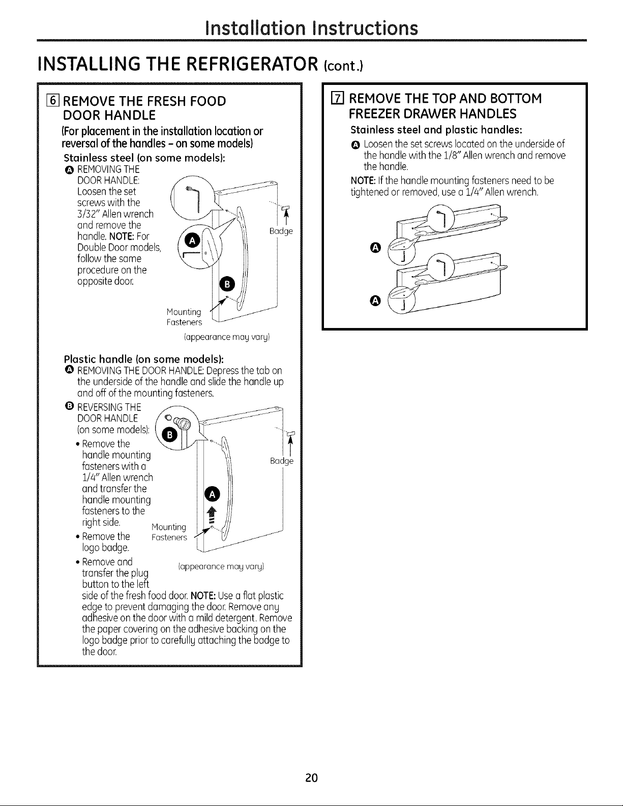
[] REMOVE THE FRESH FOOD
DOOR HANDLE
(Forplacement in the installation location or
reversal of the handles - on some models)
Stainless steel (on some models):
Q REHOVINGTHE
DOORHANDLE:
Loosenthe set
screwswith the
3/32" Allenwrench
and remove the
handle.NOTE:For
DoubleDoor models,
follow the same
procedure on the
opposite door.
Mounting
Fasteners
(appearance mag varg)
Plastic handle (on some models):
I_ REMOVINGTHEDOORHANDLE:Depressthetab on
the underside of the handle and slide the handle up
and off of the mounting fasteners.
Q
REVERSINGTHE
DOORHANDLE
(onsome models):
• Removethe
handle mounting
fasteners with a
1/4" Allen wrench
and transfer the
handle mounting
fasteners to the
right side.
• Removethe Fasteners
logo badge.
• Removeand (appearancemagvarg)
transfer the plug
button to the left
side ofthe fresh food door,NOTE:Usea flat plastic
edgeto preventdamagingthe door.Removeang
adhesive on the door with a mild detergent, Remove
the paper covering on the adhesivebacking on the
logo badge prior to carefullg attaching the badge to
the door.
Haunting
[] REMOVE THE TOP AND BOTTOM
FREEZER DRAWER HANDLES
Stainless steel and plastic handles:
O Loosenthe set screwslocated on the undersideof
the handle with the 1/8" Allenwrench and remove
the handle.
NOTE:Ifthe handle mounting fasteners need to be
tightened or removed,usea 1/4" Allenwrench.
Badge
@
Badge
2O
Installation Instructions
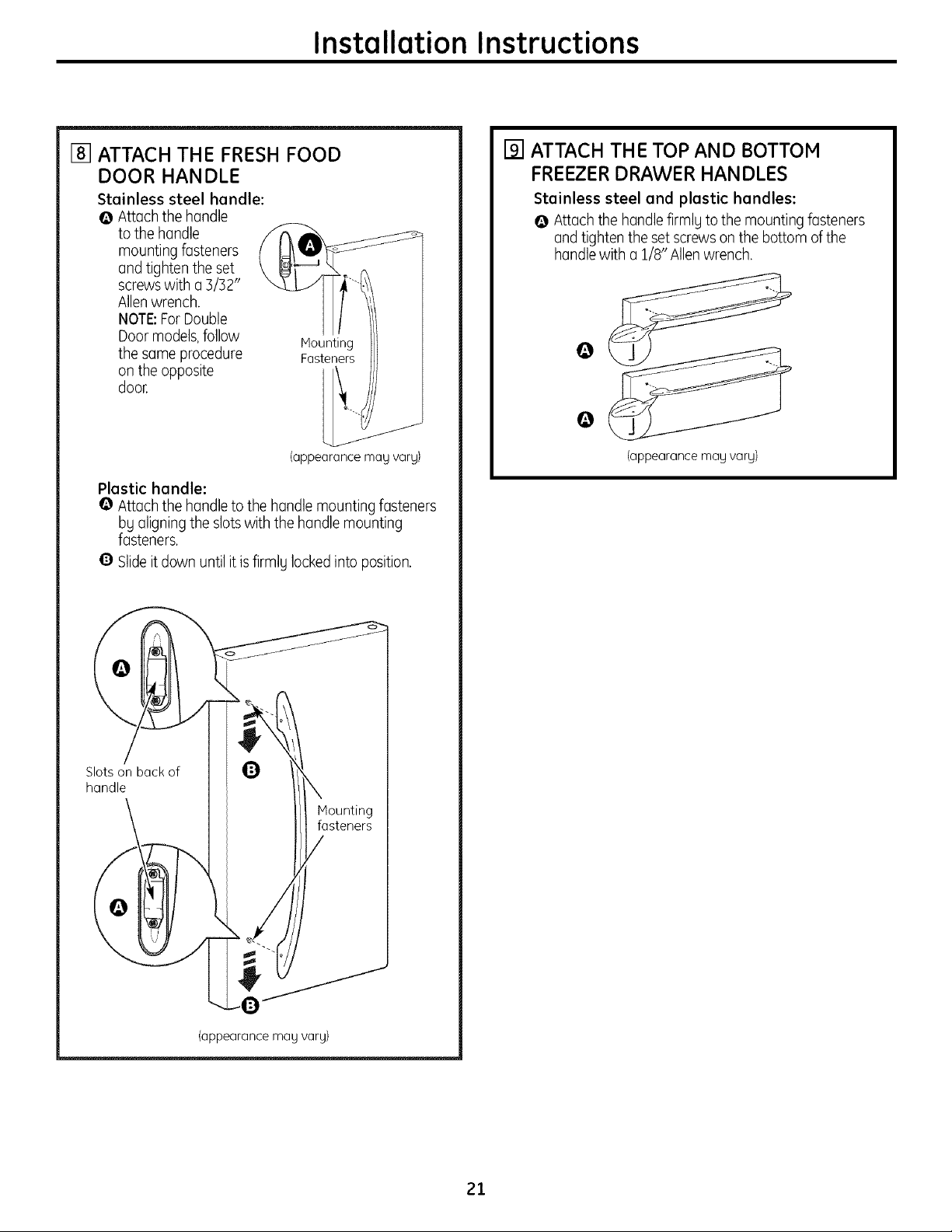
[] ATTACH THE FRESH FOOD
DOOR HANDLE
Stainless steel handle:
@ Attach the handle
to the handle
mounting fasteners
and tighten the set
screwswith a 3/32"
Allenwrench.
NOTE:ForDouble
Door models,follow
the same procedure
on the opposite
door,
Plastic handle:
O Attach the handle to the handle mounting fasteners
bUaligning the slots with the handle mounting
fasteners.
@ Slideitdown until it is firmlUlockedinto position.
Mounting
Fasteners
(appearance may vary)
[] ATTACH THE TOP AND BOTTOM
FREEZERDRAWER HANDLES
Stainless steel and plastic handles:
@ Attach the handlefirmlUto the mounting fasteners
and tighten the set screwson the bottom of the
handle with a 1/8" Allenwrench.
(appearancemaNvary)
Slotson backof U
handle
(appearance may vary)
A
Mounting
fasteners
21
Installation Instructions
INSTALLING THE REFRIGERATOR(cont.)
[] LEVEL THE REFRIGERATOR
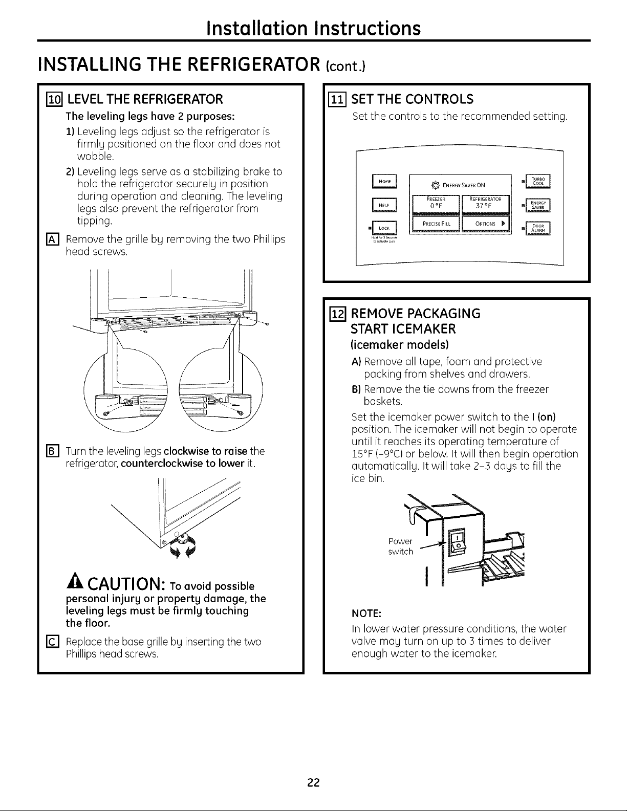
The leveling legs have 2 purposes:
2) Leveling legs adjust so the refrigerator is
firmlg positioned on the floor and does not
wobble.
2) Leveling legs serve as a stabilizing brake to
hold the refrigerator securelg in position
during operation and cleaning. The leveling
legs also prevent the refrigerator from
tipping.
[] Remove the grille bg removing the two Phillips
head screws.
[] Turn the leveling legs clockwise to raise the
refrigerator, counterclockwise to lower it.
[] SET THE CONTROLS
Set the controls to the recommended setting.
"_ ENERGY SAVER ON
.rzq
REMOVE PACKAGING
START ICEMAKER
(icemoker models)
A) Remove all tape, foam and protective
packing from shelves and drawers,
13)Remove the tie downs from the freezer
baskets.
Set the icemaker power switch to the I (on)
position. The icemaker will not begin to operate
until it reaches its operating temperature of
15°F (-9°C) or below. It will then begin operation
automaticallg, It will take 2-3 dags to fill the
ice bin.
_-/kCAUTION: To avoid possible
personal injurg or propertg damage, the
leveling legs must be firmlg touching
the floor.
[] Replace the base grille bg inserting the two
Phillips head screws.
NOTE:
In lower water pressure conditions, the water
valve mag turn on up to 3 times to deliver
enough water to the icemaken
22

Installation Instructions
REMOVING THE FREEZER DRAWERS
The freezer drawers cGn be removed, if needed, to fit
through tight areas.
Read these instructions completelg and carefullg.
TOP DRAWER
[]
REMOVE THE BASKET
[]
Open the freezer drawer until it stops.
[]
Cut the 2 wire ties off of the basket with wire
cutters,
Lift the front end of the basket so that the front
[]
two alignment tabs come out of the slide
bracket first.
[]
Then rotate the front edge of the drawer up
while lifting the remaining two rear alignment
tabs out of the slide bracket. Pull the basket up
and out ofthe drawee
[] REMOVE THE DRAWER FRONT FROM
THE SLIDES
[] Remove the 8 hex head screws from the door
and remove the door.
\
[] Set the drawer front on a non-scratching
surface.
[] Push the rail assemblies back into the cabinet.
23
Installation Instructions
REMOVING THE FREEZER DRAWERS (cont.)
The freezer drawers can be removed, if needed, to
fit through tight areas.
Read these instructions completely and carefully.
BOTTOM DRAWER
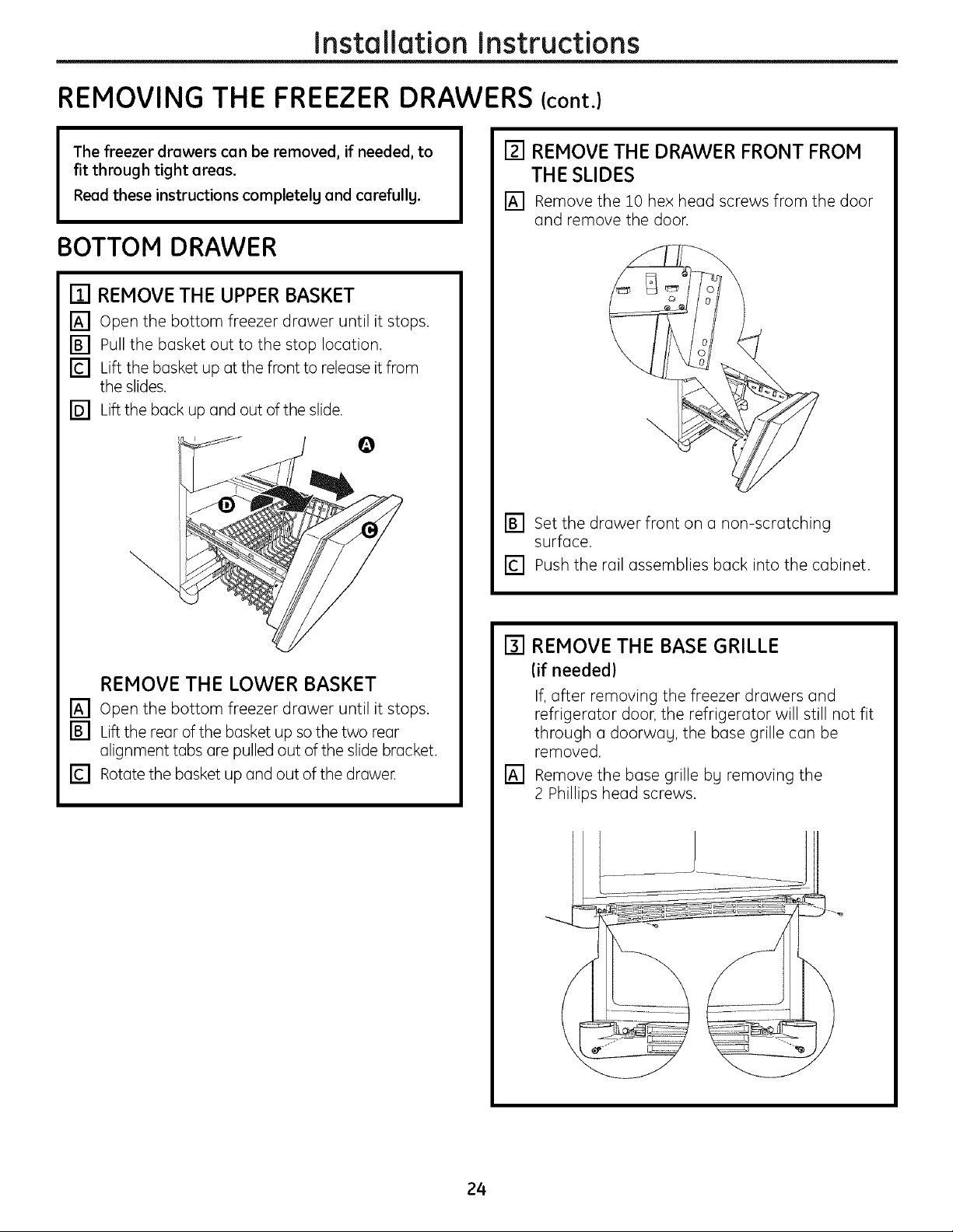
[] REMOVE THE UPPER BASKET
[] Open the bottom freezer drawer until it stops.
[] Pull the basket out to the stop location.
[] Lift the basket up at the front to release it from
the slides.
[] Lift the back up and out of the slide.
[] REMOVE THE DRAWER FRONT FROM
THE SLIDES
[] Remove the 10 hex head screws from the door
and remove the door.
\
[] Set the drawer front on a non-scratching
surface.
[] Push the rail assemblies back into the cabinet.
REMOVE THE LOWER BASKET
[] Open the bottom freezer drawer until it stops.
[] Lift the rear of the basket up so the two rear
alignment tabs are pulled out of the slide bracket.
[] Rotate the basket up and out of the drawe[
[] REMOVE THE BASE GRILLE
lif needed)
If, after removing the freezer drawers and
refrigerator door, the refrigerator will still not fit
through a doorwag, the base grille can be
removed.
[] Remove the base grille bg removing the
2 Phillips head screws.
24
Installation Instructions
REPLACING THE FREEZER DRAWERS
[] REPLACE THE FREEZER BASKET
kZJ
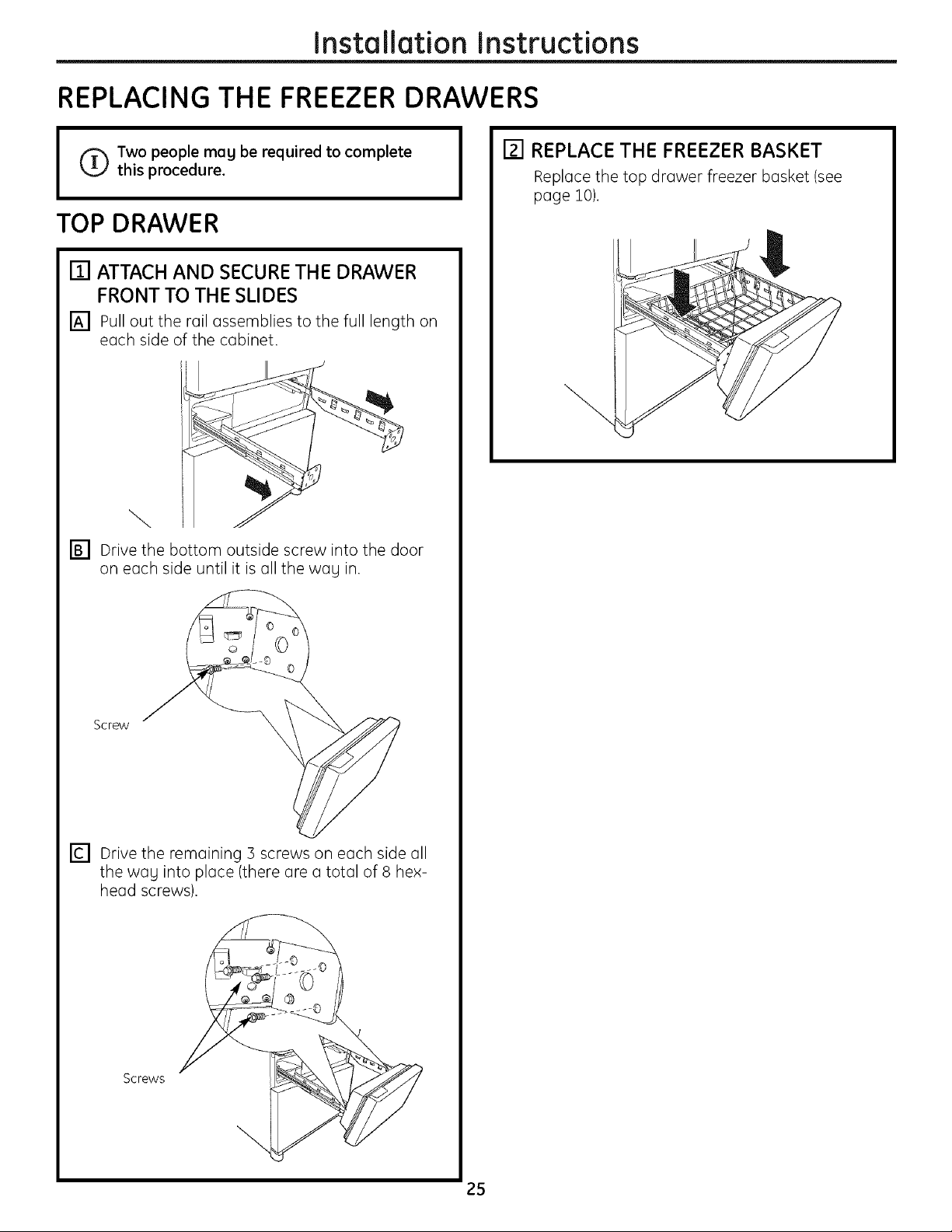
I _ Two people may be required to complete
TOP DRAWER
[] ATTACH AND SECURETHE DRAWER
[] Pull out the rail assemblies to the full length on
this procedure.
FRONT TO THE SLIDES
each side of the cabinet.
Replace the top drawer freezer basket (see
page 10),
\
[] Drive the bottom outside screw into the door
on each side until it is all the wag in.
Screw
[] Drive the remaining 3 screws on each side all
the wag into place (there are a total of 8 hex-
head screws).
Screws
25
Installation Instructions
REPLACING THE FREEZER DRAWERS (cont.)
[] ATTACH AND SECURETHE DRAWER
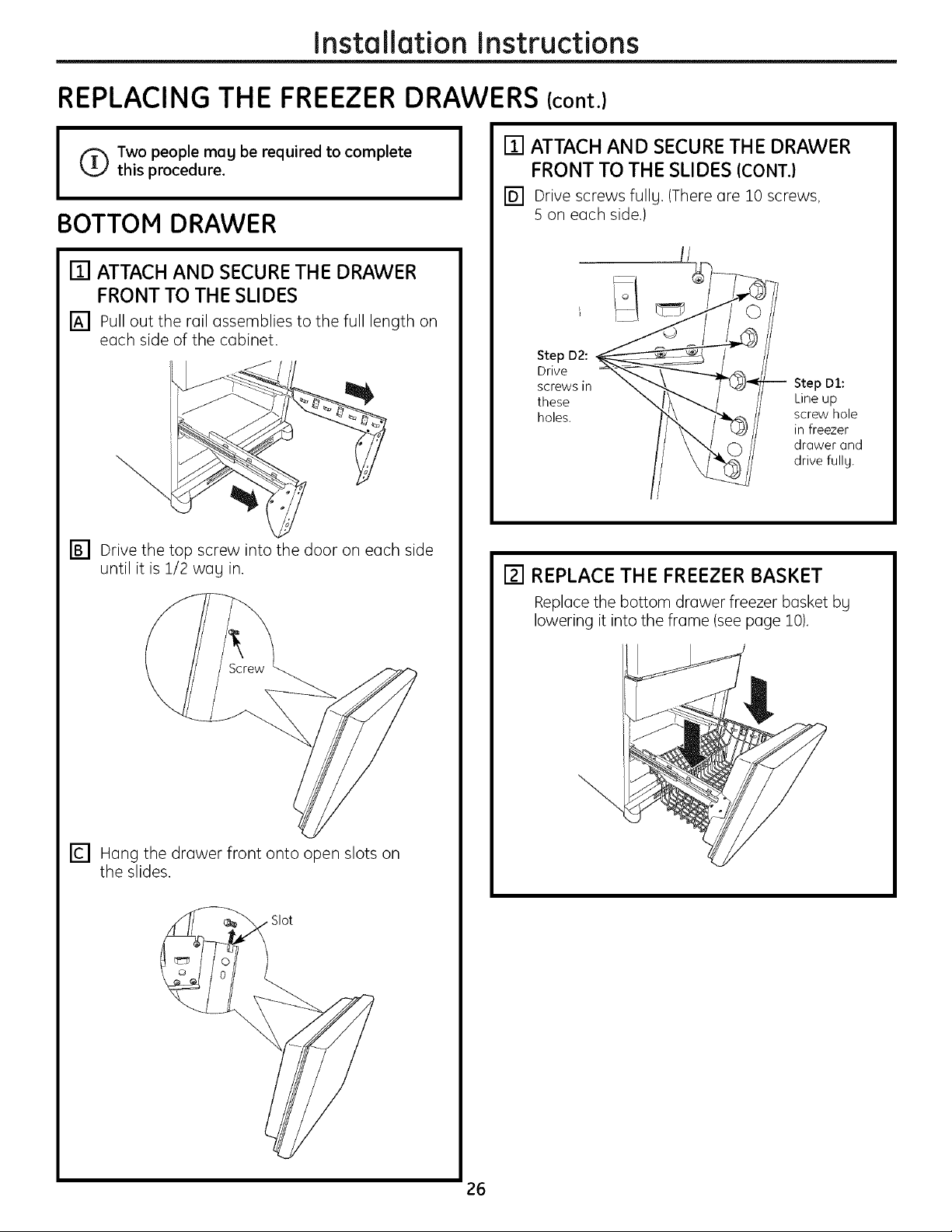
I _ Two people may be required to complete
this procedure.
BOTTOM DRAWER
[] ATTACH AND SECURETHE DRAWER
FRONT TO THE SLIDES
[] Pull out the rail assemblies to the full length on
each side of the cabinet.
FRONT TO THE SLIDES ICONT.}
[] Drive screws fullg. (There are 10 screws,
S on each side.)
Step D2:
Drive
screws in
these
holes.
Step DI:
Line up
screw hole
in freezer
drawer and
drive fully.
[] Drive the top screw into the door on each side
until it is 1/2 wag in.
[] Hang the drawer front onto open slots on
the slides.
[] REPLACE THE FREEZER BASKET
Replace the bottom drawer freezer basket bg
lowering it into the frame (see page 10),
Slot
26
Installation Instructions
REMOVING THE DOORS (Double Door Refrigerator Models onlg)
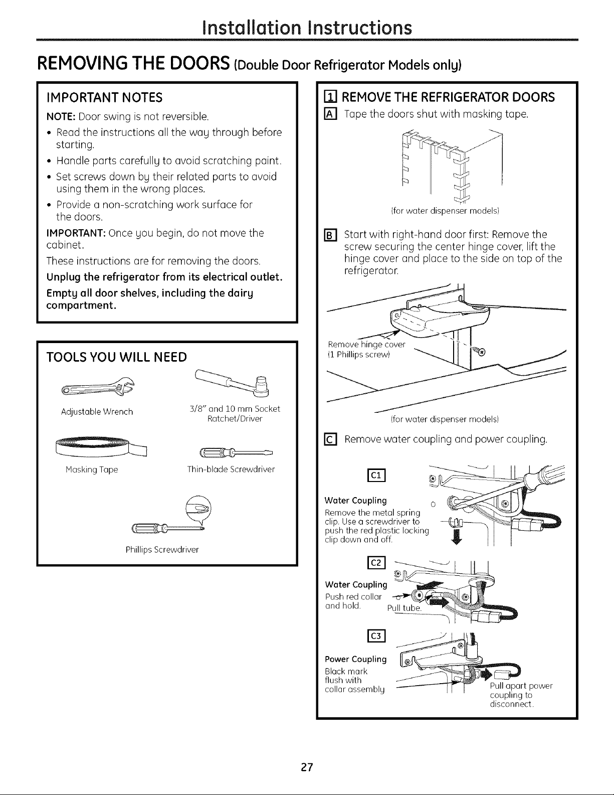
IMPORTANT NOTES
NOTE: Door swing is not reversible.
• Read the instructions all the wag through before
starting.
• Handle parts carefullg to avoid scratching paint.
• Set screws down bg their related parts to avoid
using them in the wrong places.
• Provide a non-scratching work surface for
the doors.
IMPORTANT: Once gou begin, do not move the
cabinet.
These instructions are for removing the doors.
Unplug the refrigerator from its electrical outlet.
Empty all door shelves, including the dairy
compartment.
TOOLS YOU WILL NEED
[] REMOVE THE REFRIGERATOR DOORS
[] Tape the doors shut with masking tape.
(for water dispenser models)
Start with right-hand door first: Remove the
[]
screw securing the center hinge cover, lift the
hinge cover and place to the side on top of the
refrigerator.
Remov__
Adjustable Wrench
MaskingTape
Phillips Screwdriver
3/8" and 10 mm Socket
Ratchet/Driver
Thin-blade Screwdriver
(for water dispenser models)
[] Removewater coupling and power coupling.
Water Coupling o
Remove the metal spring
clip.Usea screwdriverto
pushthe red plasticlocking
clipdown and off.
Power Coupling
Black mark
flush with
collar assembly
Pullapart power
coupling to
disconnect.
27
Installation Instructions
REMOVING THE DOORS (Double Door Refrigerator Models only)(cont.)
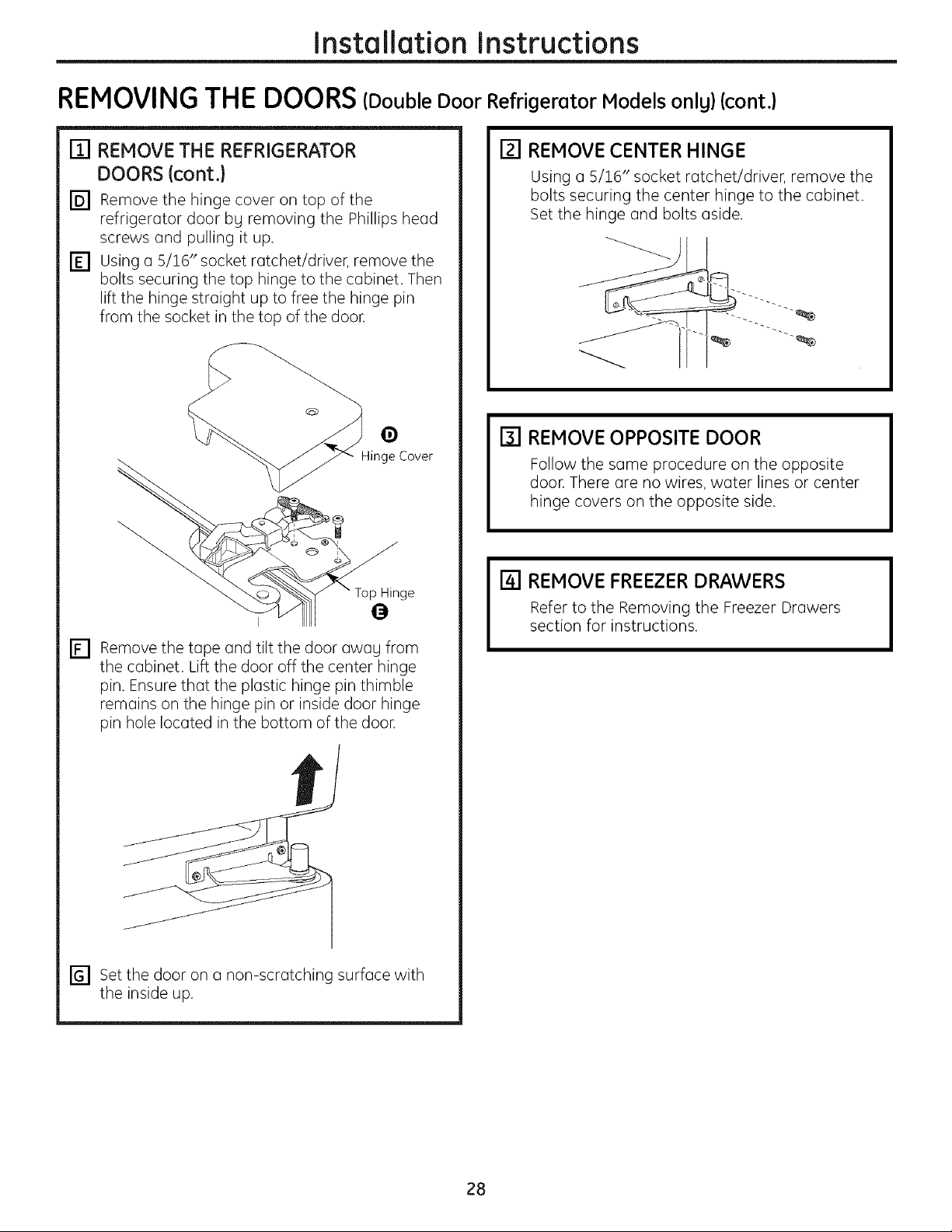
[] REMOVE THE REFRIGERATOR
DOORS(cont.}
[] Remove the hinge cover on top of the
refrigerator door bg removing the Phillips head
screws and pulling it up.
[] Using a 5/16" socket ratchet/driver, remove the
bolts securing the top hinge to the cabinet. Then
lift the hinge straight up to free the hinge pin
from the socket in the top of the door.
0
Hinge over
ge
[] REMOVE CENTER HINGE
Using a 5/16" socket ratchet/driver, remove the
bolts securing the center hinge to the cabinet.
Set the hinge and bolts aside.
[] REMOVE OPPOSITE DOOR
Follow the same procedure on the opposite
door. There are no wires, water lines or center
hinge covers on the opposite side.
[] REMOVE FREEZER DRAWERS
[] Remove the tape and tilt the door awag from
the cabinet. Lift the door off the center hinge
pin. Ensure that the plastic hinge pin thimble
remains on the hinge pin or inside door hinge
pin hole located in the bottom of the door.
[] Set the door on a non-scratching surface with
the inside up.
Refer to the Removing the Freezer Drawers
section for instructions.
28
Installation Instructions
REPLACI NG THE DOO RS(Double Door Refrigerator Models onlg)
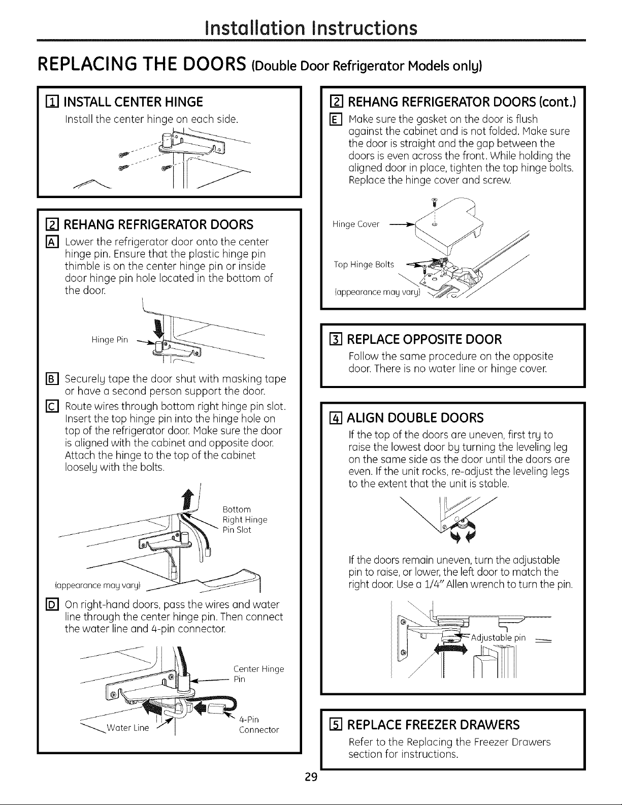
[] INSTALL CENTER HINGE
Install the center hinge on each side.
[] REHANG REFRIGERATOR DOORS
[] Lower the refrigerator door onto the center
hinge pin. Ensure that the plastic hinge pin
thimble is on the center hinge pin or inside
door hinge pin hole located in the bottom of
the door.
Hinge Pin _
[]
Securelg tape the door shut with masking tape
or have a second person support the door.
[]
Route wires through bottom right hinge pin slot.
Insert the top hinge pin into the hinge hole on
top of the refrigerator door. Hake sure the door
is aligned with the cabinet and opposite doon
Attach the hinge to the top of the cabinet
Iooselg with the bolts.
[]
REHANG REFRIGERATOR DOORS (cont.)
[]
Hake sure the gasket on the door is flush
against the cabinet and is not folded. Hake sure
the door is straight and the gap between the
doors is even across the front. While holding the
aligned door in place, tighten the top hinge bolts.
Replace the hinge cover and screw.
Hinge Cover- _ @
i_P iiiilci_t/i _
(pp y ary) _c,>../_
[] REPLACE OPPOSITE DOOR
Follow the same procedure on the opposite
door. There is no water line or hinge cover.
[] ALIGN DOUBLE DOORS
If the top of the doors are uneven, first trg to
raise the lowest door bg turning the leveling leg
on the same side as the door until the doors are
even. If the unit rocks, re-adjust the leveling legs
to the extent that the unit is stable.
Bottom
Right Hinge
Pin Slot
(appearance may vary)
[] On right-hand doors, pass the wires and water
line through the center hinge pin. Then connect
the water line and 4-pin connector.
Center Hinge
Pin
If the doors remain uneven, turn the adjustable
pin to raise, or lower, the left door to match the
right door. Use a 1/4"Allen wrench to turn the pin.
[] REPLACE FREEZER DRAWERS
Refer to the Replacing the Freezer Drawers
section for instructions.
29
installation Instructions
INSTALLING THE WATER LINE (ICEMAKER MODELS)
BEFORE YOU BEGIN
Recommended copper water supplg kits are WX8X2,
WX8X3 or WX8X4, depending on the amount of tubing
gou need. Approved plastic water supplg lines are GE
SmartConnect T"Refrigerator Tubing (WXO8XIO006,
WX08X10015 and WX08X10025).
When connecting your refrigerator to a GE Reverse
Osmosis Water System, the only approved installation
iswith a GE RVKit. For other reverse osmosis water
systems, follow the manufacturer's recommendations.
If the water supply to the refrigerator is from a
Reverse Osmosis Water Filtration System AND
the refrigerator also has a water filter, use the
refrigerator's filter bypass plug. Using the
refrigerator's water filtration cartridge in
conjunction with the RO filter can result in
hollow ice cubes.
This water line installation is not warranted by
the refrigerator or icemaker manufacturer. Follow
these instructions carefully to minimize the risk of
expensive water damage.
Water hammer (water banging in the pipes)
in house plumbing can cause damage to
refrigerator parts and lead to water leakage or
flooding. Call a qualified plumber to correct water
hammer before installing the water supplg line to
the refrigerator.
To prevent burns and product damage, do not hook
up the water line to the hot water line.
If gou use your refrigerator before connecting the
water line, make sure the icemaker power switch is
in the O {off) position.
Do not install the icemaker tubing in areas where
temperatures fall below freezing.
When using any electrical device (such as a power
drill) during installation, be sure the device is double
insulated or grounded in a manner to prevent the
hazard of electric shock, or is battery powered.
All installations must be in accordance with local
plumbing code requirements.
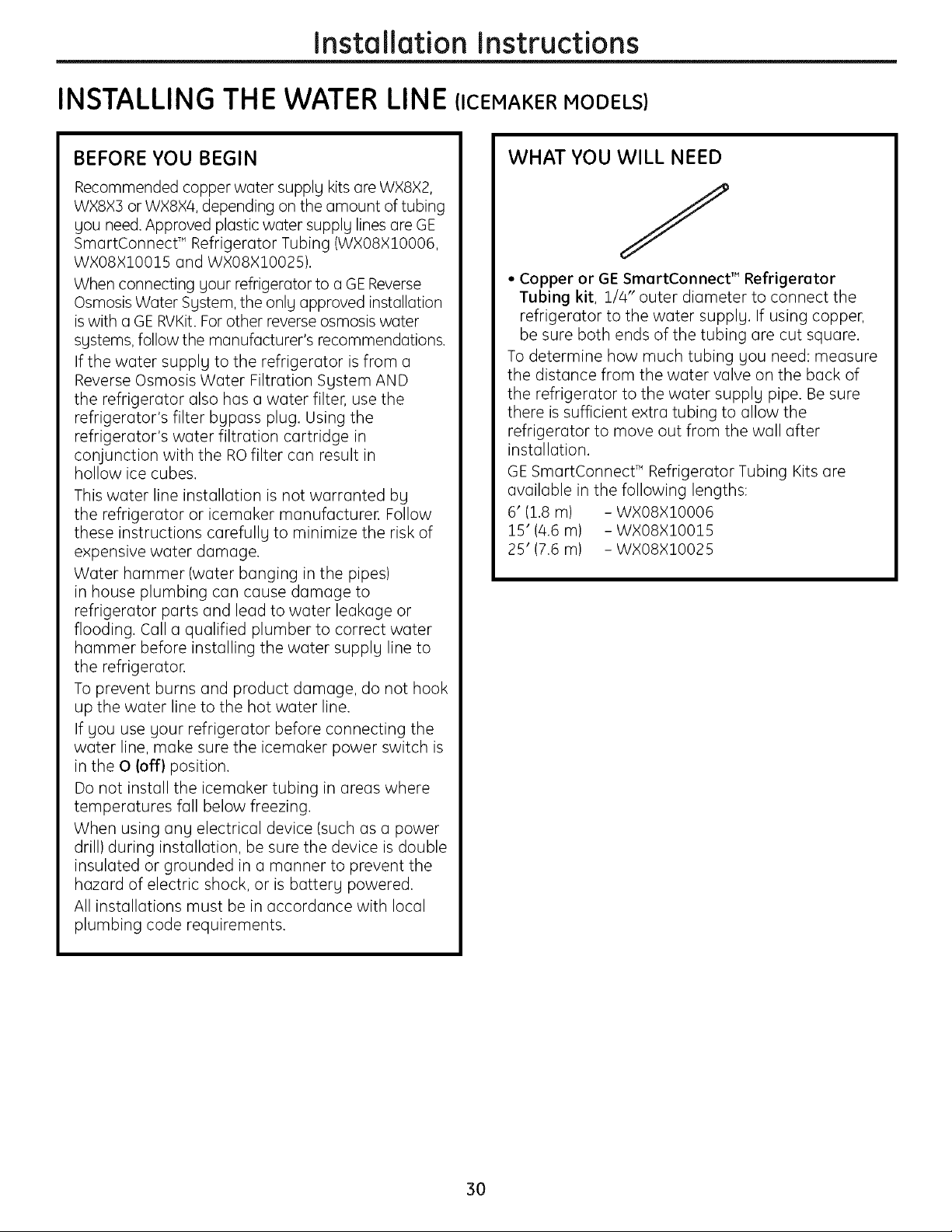
WHAT YOU WILL NEED
• Copper or GE SmartConnect TM Refrigerator
Tubing kit, 1/4" outer diameter to connect the
refrigerator to the water supplg. If using copper,
be sure both ends of the tubing are cut square.
To determine how much tubing gou need: measure
the distance from the water valve on the back of
the refrigerator to the water supplg pipe. Be sure
there is sufficient extra tubing to allow the
refrigerator to move out from the wall after
installation.
GE SmartConnect T'Refrigerator Tubing Kits are
available in the following lengths:
6' (1.8 m) - WXO8XIO006
15'(4.6 m) - WXO8X10015
25' (7.6 m) - WXO8X10025
3O
 Loading...