

Page 1
GEAppliances.com
Safety Information ............ 2
¢3
L._
-O
(--
O
U3
¢3
L9
Wa rra nty ........................ 8
Assistance /
Parts and Accessories ......... 9
Using The Cooktop
Cooktop Features ................. 10
Surface Burners ................... 11
Using The Downdraft
Vent System ..................... 12
Care and Cleaning
Cleaning The Cooktop ............. 13
Cleaning the Gloss Cooktop ........ 15
Installation Instructions ...... 17
Troubleshooting Tips ......... 35
PGP9830
PGP989
For a Spanish version of this
manual, visit our Website at
GEAppliances.com.
Para consultar una version
en espaflol de este manual
de instrucciones, visite
nuestro sitio de internet
GEAppliances.com.
Write the model and serial
numbers here:
Model #
Serial #
Find these numbers on a label
under the cooktop, on the side
of the vent chamber.
49-80516-4 03-15 GE
Page 2
Z
O
g
IMPORTANT SAFETY INFORMATION.
READ ALL INSTRUCTIONS BEFORE USING.
_E
O
I.i_
Z
!
>.
I--
I.U
i1
i_,WARNING i
For your safety, the information in this manual must be followed to minimize the risk of fire or explosion,
electric shock, or to prevent property damage, personal injury or loss of life,
WARNING: ifthe information in
this manual is not followed exactly, a fire
or explosion may result, causing property
damage, personal injury or death,
Do not store or use gasoline or other
flammable vapors and liquids in the
vicinity of this or any other appliance.
WHAT TO DO IF YOU
SMELL GAS
[] Do not try to light any appliance.
[] Do not touch any electrical switch; do
not use any phone in your building.
[] Immediately call your gas supplier
from a neighbor's phone. Follow the
gas supplier's instructions.
[] If you cannot reach your gas supplier,
call the fire department.
Installation and service must be
performed by a qualified installer, service
agency or the gas supplier.
GAS-FIRED
LISTED
SAVETHESEINSTRUCTIONS
49 80516 4
Page 3
STATE OF CALIFORNIA PROPOSITION 65 WARNING
(,D
3>
-r'l
rT'l
--i
.,<
The California Safe Drinking Water and Toxic Enforcement Act requires the Governor of California to
publish a list of substances known to the state to cause cancer, birth defects or other reproductive harm,
and requires businesses to warn customers of potential exposure to such substances.
IA WARNING IThisproductcontains one or more chemical known to the Sate of California to
cause cancer, birth defects or other reproductive harm.
Self-clean ovens can cause low-level exposure to some of these substances, including carbon monoxide,
during the cleaning cycle. Exposure can be minimized by venting with an open window or using a
ventilation fan or hood.
IAWARNING 1GENERAL SAFETY INSTRUCTIONS
Have the installer show you the location of the cooktop gas shut-off valve and how to shut it off if necessary.
[] Have your cooktop installed and properly
grounded by a qualified installer, in accordance
with the Installation Instructions. Any adjustment
and service should be performed only by
qualified gas cooktop installers or service
technicians.
[] Do not attempt to repair or replace any
part of your cooktop unless it is specifically
recommended in this manual. All other service
should be referred to a qualified technician.
[] Locate the cooktop out of kitchen traffic path and
out of drafty locations to prevent poor burner
performance.
[] Plug your cooktop into a 120-volt grounded outlet
only. Do not remove the round grounding prong
from the plug. If in doubt about the grounding
of the home electrical system, it is your
personal responsibility and obligation to have
an ungrounded outlet replaced with a properly
grounded, three-prong outlet in accordance with
the National Electrical Code. Do not use an
extension cord with this appliance.
[] Let the burner grates and other surfaces cool
before touching them or leaving them where
children can reach them.
[] Be sure all packaging materials are removed
from the cooktop before operating it to prevent
fire or smoke damage should the packaging
material ignite.
Be sure your cooktop is correctly adjusted by
a qualified service technician or installer for
the type of gas (natural or LP) which is to be
used. Your cooktop can be converted for use
with either type of gas. See the Installation
Instructions in the LP Conversion Kit.
A WARNING: These adjustments must
be made by a qualified service technician in
accordance with the manufacturer's instructions
and all codes and requirements of the authority
having jurisdiction. Failure to follow these
instructions could result in serious injury
or property damage. The qualified agency
performing this work assumes responsibility for
the conversion.
[] Do not leave children alone or unattended where
a cooktop is hot or in operation. They could be
seriously burned.
[] Do not allow anyone to climb, stand or hang on
the cooktop.
[] Do not operate or clean your cooktop if the glass
is broken or cracked. Cleaning solutions and
spillovers could penetrate the broken cooktop and
create a risk of electric shock. Call for service
immediately if the cooktop glass breaks or cracks.
Z
"TI
O
Z
!
O
49 80516 4
SAVETHESEINSTRUCTIONS
Page 4
Z
O
g
O
Z
!
I---
I1
u')
IMPORTANT SAFETY INFORMATION.
READ ALL INSTRUCTIONS BEFORE USING.
IAWARNING IGENERAL SAFETY INSTRUCTIONS
[]
[] A CAUTION •Itemsofinteresttochildren
should not be stored in cabinets above a
cooktop--children climbing on the cooktop to
reach items could be seriously injured.
[] Always keep wooden and plastic utensils and
canned food a safe distance away from your
cooktop.
[] Always keep combustible wall coverings, curtains
or drapes a safe distance from your cooktop.
[] Do not obstruct the flow of combustion and
ventilation air.
[] Leak testing of the appliance shall be conducted
according to the manufacturer's instructions.
[] Never wear loose-fitting or hanging garments
while using the appliance. Be careful when
reaching for items stored in cabinets over the
cooktop. Flammable material could be ignited if
brought in contact with flame or hot surfaces and
may cause severe burns.
[] Teach children not to play with the controls or
any other part of the cooktop.
AWARNING: NEVER use this appliance
as a space heater to heat or warm the room.
Doing so may result in carbon monoxide
poisoning and overheating of the oven.
[] Always keep dish towels, dishcloths, pot holders
and other linens a safe distance from your
cooktop.
[] Do not store flammable materials near a cooktop.
[] Do not store or use combustible materials,
gasoline or other flammable vapors and liquids in
the vicinity of this or any other appliance.
[] Do not let cooking grease or other flammable
materials accumulate on or near the cooktop.
[] Do not operate the burner without all burner parts
in place.
[] Do not place hot cookware on the glass cooktop.
This could cause glass to break.
[] Do not clean the cooktop with flammable or
volatile cleaning fluids.
[] Do not clean the cooktop when the appliance is
in use.
Avoid scratching the cooktop with sharp
instruments, or with rings and other jewelry.
[]
Never use the cooktop as a cutting board.
[]
Do not use water on grease fires. Never pick up
a flaming pan. Turn the controls off. Smother a
flaming pan on a surface burner by covering the
pan completely with a well-fitting lid, cookie sheet
or flat tray. Use a multi-purpose dry chemical or
foam-type fire extinguisher.
Flaming grease outside a pan can be put out by
covering it with baking soda or, if available, by
using a multi-purpose dry chemical or foam-type
fire extinguisher.
[]
WARNING: To reduce the risk of fire,
electrical shock or injury to persons, observe the
following:
A. Use this unit only in the manner intended
by the manufacturer. If you have questions,
contact the manufacturer.
B. Before servicing or cleaning the unit, switch
power off at service panel.
C. When cutting or drilling into wall or ceiling, do
not damage electrical wiring and other hidden
utilities.
D. Ducted fans must always be vented to the
outdoors.
E. To reduce the risk of fire, use only metal
ductwork.
F. Do not flame foods on the cooktop. If you do
flame foods under the hood, turn the fan on.
G. Sufficient air is needed for proper combustion
and exhausting of gases through the flue
(chimney) of fuel burning equipment to
prevent back drafting. Follow the heating
equipment manufacturer's guidelines and
safety standards, such as those published
by the National Fire Protection Association
(NFPA), the American Society for Heating,
Refrigeration and Air Conditioning Engineers
(ASHRAE) and the local code authorities.
When applicable, install any make up
(replacement) air system in accordance
with local building code requirements. Visit
GEAppliances.com for available makeup
air solutions.
SAVETHESEINSTRUCTIONS
49 80516 4
Page 5
(AWARNING 1GENERAL SAFETY INSTRUCTIONS
"r'l
rl'l
-4
.<
AWARNING. To reduce the risk of a
cooktop grease fire:
A. Keep fan, filters and grease-laden surfaces
clean.
B. Always turn vent ON when cooking at high
heat.
C. Use high settings on cooktop only when
necessary. Heat oil slowly on low to medium
setting.
Do Don't leave the cooktop unattended when
cooking.
E. Always use cookware and utensils
appropriate for the type and amount of food
being prepared.
,A CAUTION: For general ventilating
use only. Do not use to exhaust hazardous or
explosive materials and vapors.
[AWARNING !GLASS COOKTOP SURFACE
Use care when touching the glass cooktop surface. The glass surface of the cooktop will retain heat after
the controls have been turned off.
[] Avoid scratching the glass cooktop surface. The
glass surface can be scratched with items such
as sharp instruments, rings or other jewelry and
rivets on clothing.
[] Large scratches or impacts to glass cooktops can
lead to broken or shattered glass.
[] Do not operate the cooktop if the glass is broken.
Spillovers or cleaning solution may penetrate
a broken cooktop and create a risk of electrical
shock. Contact a qualified technician immediately
should your glass cooktop surface become broken.
[] Never use the glass cooktop surface as a cutting
board.
[] Do not place or store items that can melt or catch
fire on the glass cooktop surface, even when it is
not being used.
[] Be careful when placing spoons or other stirring
utensils on glass cooktop surface when it is in use.
They may become hot and could cause burns.
[] Clean the cooktop surface with caution. (f a wet
sponge or cloth is used to wipe spills on a hot
surface, be careful to avoid steam burns. Some
cleaners can produce noxious fumes if applied to
a hot surface. NOTE: We recommend that you
avoid wiping any surface unit areas until they
have cooled and the indicator light has gone off.
Sugar spills are the exception to this. Please
see Cleaning the Glass Cooktop in the Care and
Cleaning section.
[] When the cooktop is cool, use only
CERAMA BRYTE ®Ceramic Cooktop Cleaner
and the CERAMA BRYTE ® Cleaning Pad to
clean the cooktop.
[] To avoid possible damage to the cooking
surface, do not apply cleaning cream to the glass
surface when it is hot.
[] After cleaning, use a dry cloth or paper towel to
remove all cleaning cream residue.
[] Read and follow all instructions and warnings on
the cleaning cream labels.
Z
O
Z
!
O
49 80516 4
SAVETHESEINSTRUCTIONS
Page 6
Z
O
g
IMPORTANT SAFETY INFORMATION.
READ ALL INSTRUCTIONS BEFORE USING.
IAWARNING ISURFACE BURNERS
O
Z
!
I---
I1
u')
Use proper pan size--avoid pans that are unstable or easily tipped. Select cookware having flat bottoms
large enough to cover burner grates. To avoid spillovers, make sure cookware is large enough to contain
the food properly. This will both save cleaning time and prevent hazardous accumulations of food,
since heavy spattering or spillovers left on cooktop can
grasped and remain cool.
[] Always use the LITE position when igniting the top
burners and make sure the burners have ignited.
[] Never leave the surface burners unattended at
high flame settings. Boilovers cause smoking and
greasy spillovers that may catch on fire.
[] Use only dry pot holders--moist or damp pot
holders on hot surfaces may result in burns from
steam. Do not let pot holders come near open
flames when lifting cookware. Do not use a towel
or other bulky cloth in place of a pot holder. Such
cloths can catch fire on a hot burner.
[] When using glass cookware, make sure it is
designed for cooktop cooking.
[] To minimize the possibility of burns, ignition of
flammable materials and spillage, turn cookware
handles toward the side or center of the cooktop
without extending over adjacent burners.
[] Always turn the surface burner controls off before
removing cookware.
[] Carefully watch foods being fried at a high flame
setting.
[] Always heat fat slowly and watch as it heats.
[] Do not leave any items on the cooktop. The hot
air from the vent may ignite flammable items and
will increase pressure in closed containers, which
may cause them to burst.
ignite. Use pans with handles that can be easily
[] If a combination of oils or fats will be used in frying,
stir together before heating or as fats melt slowly.
[] Do not use a wok on the cooking surface if the
wok has a round metal ring that is placed over
the burner grate to support the wok. This ring
acts as a heat trap, which may damage the
burner grate and burner head. Also, it may cause
the burner to work improperly. This may cause
a carbon monoxide level above that allowed by
current standards, resulting in a health hazard.
[] Foods for frying should be as dry as possible.
Frost on frozen foods or moisture on fresh foods
can cause hot fat to bubble up and over the
sides of the pan.
[] Use the least possible amount of fat for effective
shallow or deep-fat frying. Filling the pan too full
of fat can cause spillovers when food is added.
[] Use a deep fat thermometer whenever possible to
prevent overheating fat beyond the smoking point.
[] Never try to move a pan of hot fat, especially a
deep fat fryer. Wait until the fat is cool.
[] Do not flame foods on the cooktop. If you do
flame foods under the hood, turn the fan on.
SAVETHESEINSTRUCTIONS
49 80516 4
Page 7
IA WARNING 1SURFACE BURNERS
I,D
:1>
"TI
r'n
-4
.<
Adjust the burner flame size so it does not extend beyond the edge of the cookware. Excessive flame is
hazardous.
[] Do not leave plastic items on the cooktop-- they
may melt if left too close to the vent.
[] Keep all plastics away from the surface burners.
[] If you smell gas, turn off the gas to the cooktop
and call a qualified service technician. Never use
an open flame to locate a leak.
[] To avoid the possibility of a burn, always be
certain that the controls for all burners are at
the off position and all grates are cool before
attempting to remove them.
[] Never clean the cooktop surface when it is hot.
Some cleaners produce noxious fumes and wet
cloths could cause steam burns if used on a hot
surface.
[] Never leave jars or cans of fat drippings on or
near your cooktop.
[] Do not use aluminum foil under burner grates.
Misuse could result in a fire hazard or damage to
the cooktop.
[] Do not cover or block the area around the
cooktop knobs. This area must be kept clear for
proper ventilation and burner performance.
[] Clean only parts listed in this Owner's Manual.
I_ WARNING 1COOK MEAT AND POULTRYTHOROUGHLY
Cook meat and poultry thoroughly--meat to at least an INTERNAL temperature of 160°F and poultry to
at least an INTERNAL temperature of 180°F. Cooking to these temperatures usually protects against
foodborne illness.
Z
-rl
O
Z
!
O
[_ WARNING i CONVERTINGTO LP GAS
(orconvertingback to naturalgas from LP)
This cooktop leaves the factory set for use with natural gas.
If you want to convert to LP gas, the conversion must be performed by a qualified LP gas installer.
The conversion instructions, conversion sticker and LP orifices can be found attached to the pressure
regulator.
There is a second set of instructions included in the envelope containing the product wiring diagrams
on the side of the cooktop. Keep these instructions and the orifices in case you want to convert back to
natural gas.
SAVETHESE INSTRUCTIONS
49 80516 4 7
Page 8
)-
I--
"_.o
Thonk You! ooofor your purchase of o GEBrand appliance.
Register Your Appliance: Register your new appliance on-line at your convenience!
www.geappliances.comlservice and supportlregisterl
Timely product registration will allow for enhanced communication and prompt service under the terms of your warranty,
should the need arise. You may also mail in the pre-printed registration card included in the packing material.
GEGos Cooktop Worronty
GEAppliances.com
All warranty service is provided by our Factory Service Centers, or an authorized Customer Care®technician.
To schedule service, on-line, visit us at www.geappliances.com/service_and_support/, or call 800.GE.CARES
(800.432.2737). Please have serial number and model number available when calling for service.
Servicing your appliance may require the use of the onboard data port for diagnostics. This gives a GE factory
service technician the ability to quickly diagnose any issues with your appliance and helps GE improve its products
by providing GE with information on your appliance. If you do not want your appliance data to be sent to GE, please
advise your technician not to submit the data to GE at the time of service.
For the period of one year from the date of the original purchase• GE will provide any part of the cooktop which
fails due to a defect in materials or workmanship• During this limited one-year warranty, GE will also provide, free of
charge, all labor and in-home service to replace the defective part.
What GEwill not cover:
[] Service trips to your home to teach you how to use
the product.
[] Improper installation, delivery or maintenance•
[] Failure of the product if it is abused, misused,
modified or used for other than the intended purpose
or used commercially•
[] Replacement of house fuses or resetting of circuit
breakers•
09
[] Damage to the product caused by accident, fire,
=._ fib
floods or acts of God.
EXCLUSION OF IMPLIED WARRANTIES
Your sole and exclusive remedy is product repair as provided in this Limited Warranty, Any implied warranties,
including the implied warranties of merchantability or fitness for a particular purpose, are limited to one year or the
shortest period allowed by law.
r-
:::9
This warranty is extended to the original purchaser and any succeeding owner for products purchased for home use
within the USA. If the product is located in an area where service by a GE Authorized Servicer is not available, you
may be responsible for a trip charge or you may be required to bring the product to an Authorized GE Service location
(_ r'-
for service• In Alaska, the warranty excludes the cost of shipping or service calls to your home.
Some states do not allow the exclusion or limitation of incidental or consequential damages• This warranty gives you
O
specific legal rights, and you may also have other rights which vary from state to state• To know what your legal rights
are, consult your local or state consumer affairs office or your state's Attorney General.
•-! fl_
Warrantor: General Electric Company. Louisville, KY40225
[] Incidental or consequential damage caused by
possible defects with this appliance•
[] Damage caused after delivery•
[] Product not accessible to provide required service.
[] Service to repair or replace light bulbs, except for
LED lamps•
[] Installation or service for a makeup (replacement)
air system.
Extended Warranties: Purchase a GE extended warranty and learn about special discounts that are available while
your warranty is still in effect. You can purchase it on-line anytime
www.geappliances.com/service and_support/shop-for-extended-service-plans.htm
or call 800•626•2224 during normal business hours. GE Consumer Home Services will still be there after your
warranty expires.
49 80516 Z_
Page 9
Have a question or need assistance with your appliance?
Try the GE Appliances Website (www.geappliances.com/service=and=support/) 24 hours a day, any day of the
year! For greater convenience and faster service, you can now download Owner's Manuals, order parts or even
schedule service on-line.
Schedule Service: Expert GE repair service is only one
step away from your door. Get on-line and schedule your
service at www.geappliances.com/service_and_support/
Or call 800.GE.CARES (800.432.2737) during normal
business hours.
Parts and Accessories: Individuals qualified to service
their own appliances can have parts or accessories sent
directly to their homes (VISA, MasterCard and Discover
cards are accepted).Order on-line today, 24 hours
every day or by phone at 800.626.2002 during normal
business hours.
Instructions contained in this manual cover procedures
to be performed by any user. Other servicing generally
should be referred to qualified service personnel. Caution
must be exercised, since improper servicing may cause
unsafe operation.
Real Life Design Studio: GE supports the Universal
Design concept of products, services and environments
that can be used by people of all ages, sizes and
capabilities. We recognize the need to design for a wide
range of physical and mental abilities and impairments.
For details of GE's Universal Design applications,
including kitchen design ideas for people with disabilities,
check out our Website today. For the hearing impaired,
please call 800.TDD.GEAC (800.833.4322).
Contact Us: If you are not satisfied with the service you
receive from GE, contact us on our Website with all the
details including your phone number, or write to:
General Manager, Customer Relations
GE Appliances, Appliance Park Louisville, KY 40225
:1>
¢D
m
I,D
Z
db
rn
---4
I,D
:I>
Z
!C!
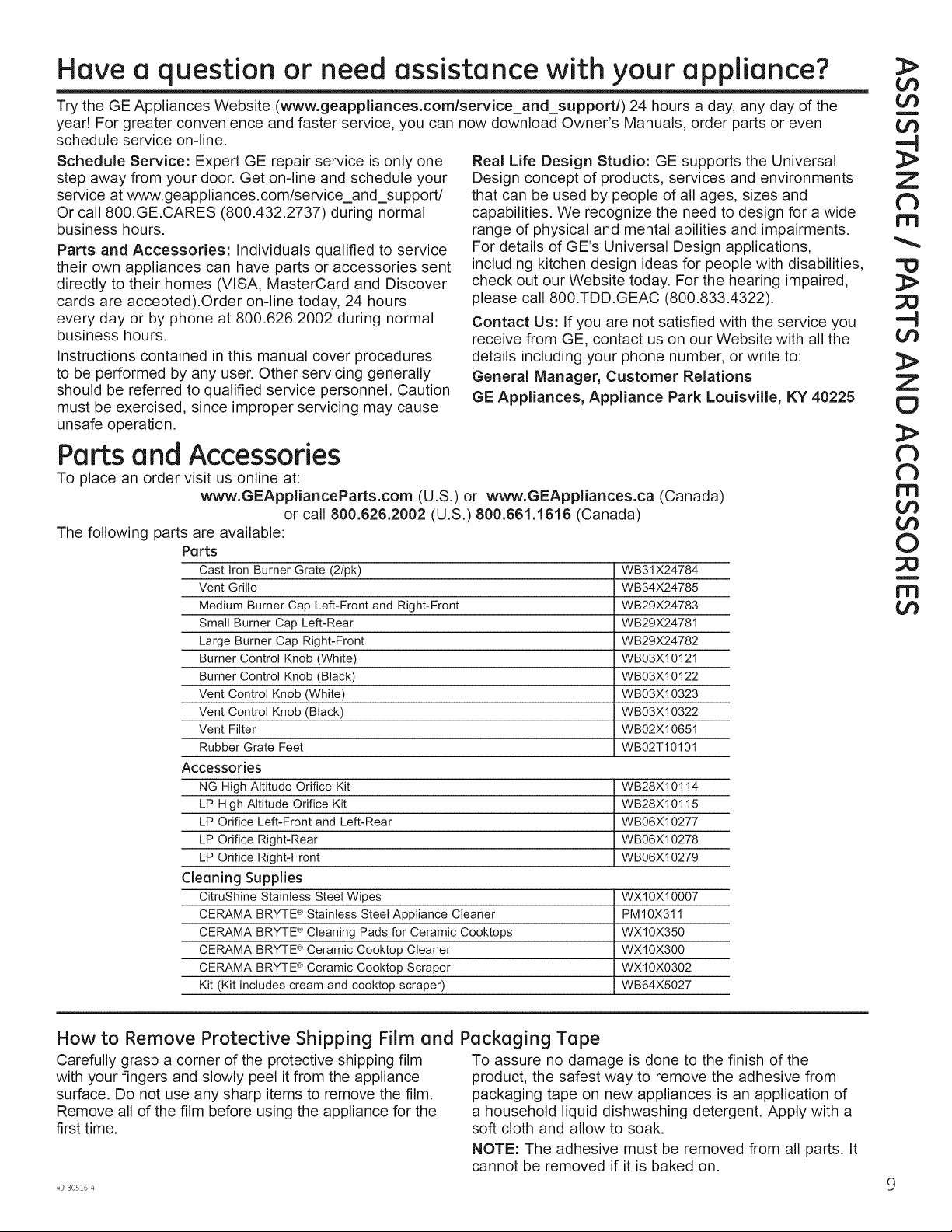
Parts and Accessories
To place an order visit us online at:
www.GEApplianceParts.com (U.S.) or www.GEAppliances.ca (Canada)
or call 800.626.2002 (U.S.) 800.661.1616 (Canada)
The following parts are available:
Parts
Cast Iron Burner Grate (2/pk) WB31X24784
Vent Grille WB34X24785
Medium Burner Cap Left-Front and Right-Front WB29X24783
Small Burner Cap Left-Rear WB29X24781
Large Burner Cap Right-Front WB29X24782
Burner Control Knob (White) WB03X10121
Burner Control Knob (Black) WB03X10122
Vent Control Knob (White) WB03X10323
Vent Control Knob (Black) WB03X10322
Vent Filter WB02X10651
Rubber Grate Feet WB02T10101
Accessories
NG High Altitude Orifice Kit WB28X10114
LP High Altitude Orifice Kit WB28X10115
LP Orifice Left-Front and Left-Rear WB06X10277
LP Orifice Right-Rear WB06X10278
LP Orifice Right-Front WB06X10279
Cleaning Supplies
CitruShine Stainless Steel Wipes WX10X10007
CERAMA BRYTE ®Stainless Steel Appliance Cleaner PM10X311
CERAMA BRYTE ®Cleaning Pads for Ceramic Cooktops WX10X350
CERAMA BRYTE ®Ceramic Cooktop Cleaner WX10X300
CERAMA BRYTE ®Ceramic Cooktop Scraper WXl0X0302
Kit (Kit includes cream and cooktop scraper) WB64X5027
db
db
rr'l
U3
I,D
O
I"1'1
¢D
How to Remove Protective Shipping Film and Packaging Tape
Carefully grasp a corner of the protective shipping film
with your fingers and slowly peel it from the appliance
surface. Do not use any sharp items to remove the film.
Remove all of the film before using the appliance for the
first time.
To assure no damage is done to the finish of the
product, the safest way to remove the adhesive from
packaging tape on new appliances is an application of
a household liquid dishwashing detergent. Apply with a
soft cloth and allow to soak.
NOTE: The adhesive must be removed from all parts. It
cannot be removed if it is baked on.
Page 10
O0
Cooktop Features
4=J
C3
(b
CL
O
4--J
X/
O
O
CP
6:
O
O
O
LLI
F-
L9
Z
i
U3
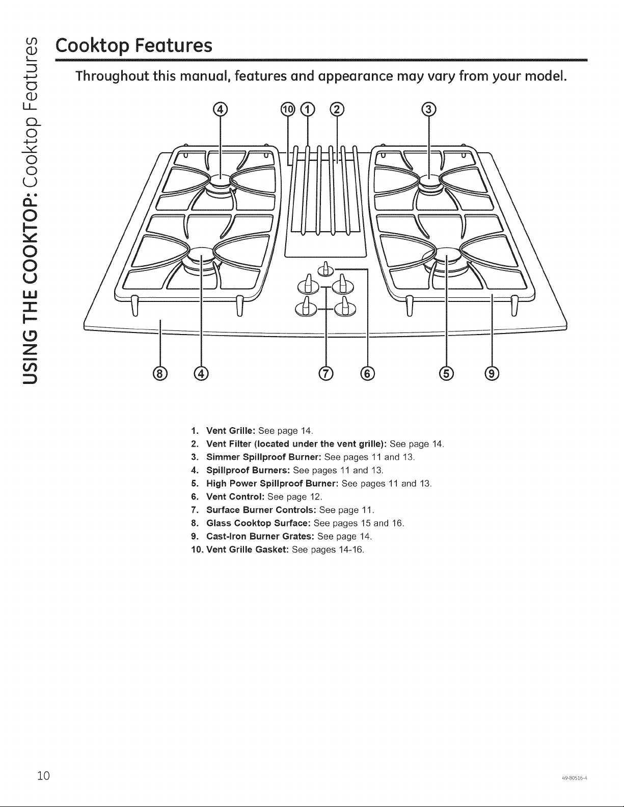
Throughout this manual, features and appearance may vary from your model.
1. Vent Grille: See page 14.
2. Vent Filter (located under the vent grille): See page 14.
3. Simmer Spillproof Burner: See pages 11 and 13.
4. Spillproof Burners: See pages 11 and 13.
5. High Power Spillproof Burner: See pages 11 and 13.
6. Vent Control: See page 12.
7. Surface Burner Controls: See page 11.
8. Glass Cooktop Surface: See pages 15 and 16.
9. Cast-Iron Burner Grates: See page 14.
10. Vent Grille Gasket: See pages 14-16.
10 49 80516 4
Page 11
Surface Burners
C:
Throughout this manual, features and appearance may vary from your model.
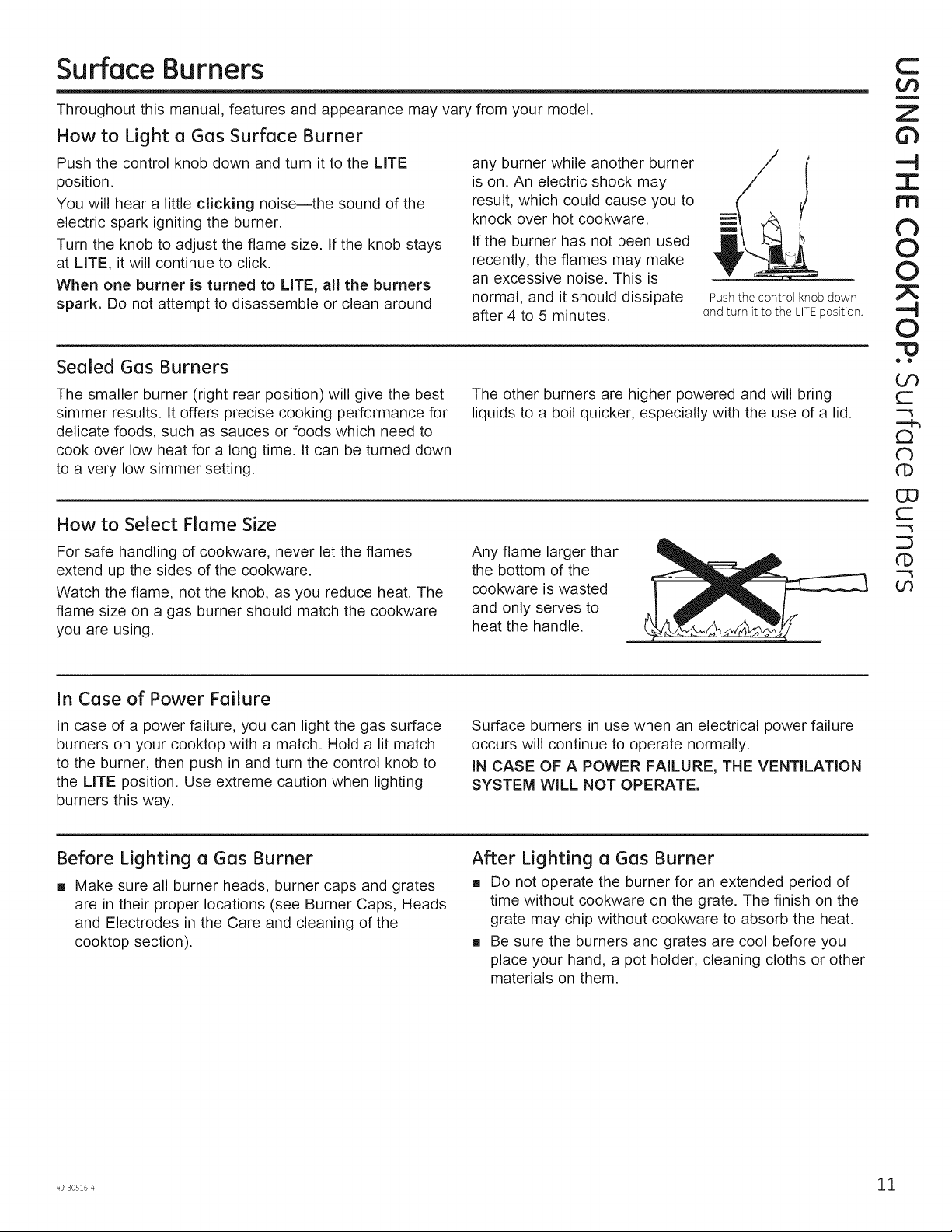
How to Light a Gas Surface Burner
Push the control knob down and turn it to the LITE
position.
You will hear a little clicking noise--the sound of the
electric spark igniting the burner.
Turn the knob to adjust the flame size. If the knob stays
at LITE, it will continue to click.
When one burner is turned to LITE, all the burners
spark. Do not attempt to disassemble or clean around
any burner while another burner
is on. An electric shock may
result, which could cause you to
knock over hot cookware.
If the burner has not been used
recently, the flames may make
an excessive noise. This is
normal, and it should dissipate
after 4 to 5 minutes.
Sealed Gas Burners
The smaller burner (right rear position) will give the best
simmer results. Itoffers precise cooking performance for
delicate foods, such as sauces or foods which need to
cook over low heat for a long time. It can be turned down
to a very low simmer setting.
The other burners are higher powered and will bring
liquids to a boil quicker, especially with the use of a lid.
How to Select Flame Size
For safe handling of cookware, never let the flames
extend up the sides of the cookware.
Watch the flame, not the knob, as you reduce heat. The
flame size on a gas burner should match the cookware
you are using.
Any flame larger than
the bottom of the
cookware is wasted
and only serves to
heat the handle.
Z
I
rn
0
0
Push the control knob down
ond turn it to the LITEposition.
0
• •
GO
C
Q
N
O3
C
GO
In Case of Power Failure
In case of a power failure, you can light the gas surface
burners on your cooktop with a match. Hold a lit match
to the burner, then push in and turn the control knob to
the LITE position. Use extreme caution when lighting
burners this way.
Before Lighting a Gas Burner
[] Make sure all burner heads, burner caps and grates
are in their proper locations (see Burner Caps, Heads
and Electrodes in the Care and cleaning of the
cooktop section).
Surface burners in use when an electrical power failure
occurs will continue to operate normally.
IN CASE OF A POWER FAILURE, THE VENTILATION
SYSTEM WILL NOT OPERATE.
After Lighting a Gas Burner
[] Do not operate the burner for an extended period of
time without cookware on the grate. The finish on the
grate may chip without cookware to absorb the heat.
[] Be sure the burners and grates are cool before you
place your hand, a pot holder, cleaning cloths or other
materials on them.
Page 12
E
CO
>,,
oO
(]J
:>
E]
L_.
-O
c-
O
Cb
c-
F--
Oh
c"
LO
U]
L_
(]J
c"
Surface Burners (Cont.)
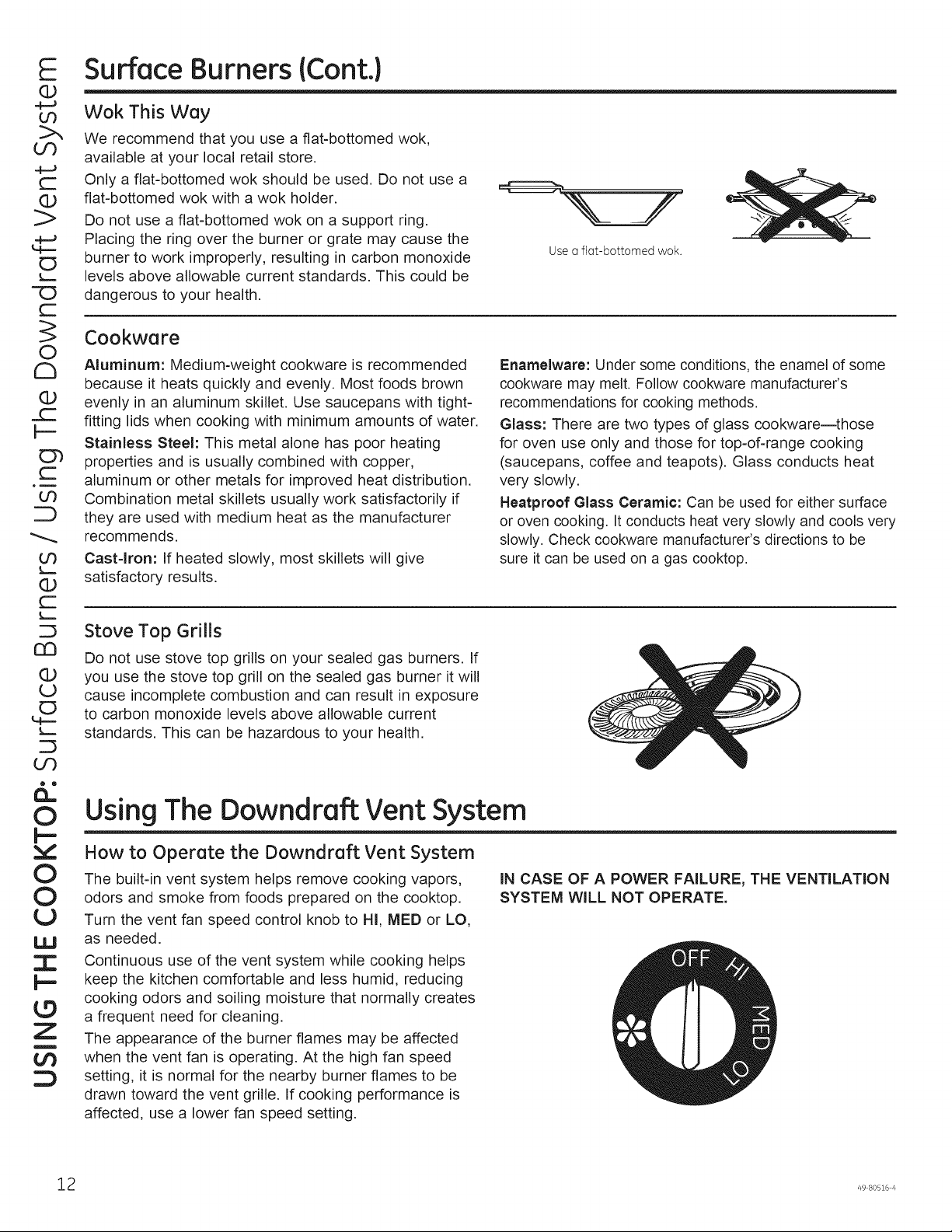
Wok This Way
We recommend that you use a flat-bottomed wok,
available at your local retail store.
Only a flat-bottomed wok should be used. Do not use a
flat-bottomed wok with a wok holder.
Do not use a flat-bottomed wok on a support ring.
Placing the ring over the burner or grate may cause the
burner to work improperly, resulting in carbon monoxide
levels above allowable current standards. This could be
dangerous to your health.
Cookware
Aluminum: Medium-weight cookware is recommended
because it heats quickly and evenly. Most foods brown
evenly in an aluminum skillet. Use saucepans with tight-
fitting lids when cooking with minimum amounts of water.
Stainless Steel: This metal alone has poor heating
properties and is usually combined with copper,
aluminum or other metals for improved heat distribution.
Combination metal skillets usually work satisfactorily if
they are used with medium heat as the manufacturer
recommends.
Cast-Iron: If heated slowly, most skillets will give
satisfactory results.
Use a flat-bottomed wok.
Enamelware: Under some conditions, the enamel of some
cookware may melt. Follow cookware manufacturer's
recommendations for cooking methods.
Glass: There are two types of glass cookware--those
for oven use only and those for top-of-range cooking
(saucepans, coffee and teapots). Glass conducts heat
very slowly.
Neatpreof Glass Ceramic: Can be used for either surface
or oven cooking. Itconducts heat very slowly and cools very
slowly. Check cookware manufacturer's directions to be
sure it can be used on a gas cooktop.
c£]
(]J
U
E]
OO
&:
O
I--
O
O
£3
UJ
I
Z
Stove Top Grills
Do not use stove top grills on your sealed gas burners. If
you use the stove top grill on the sealed gas burner it will
cause incomplete combustion and can result in exposure
to carbon monoxide levels above allowable current
standards. This can be hazardous to your health.
Using The Downdraft Vent System
How to Operate the Downdraft Vent System
The built-in vent system helps remove cooking vapors,
odors and smoke from foods prepared on the cooktop.
Turn the vent fan speed control knob to HI, MED or LO,
as needed.
Continuous use of the vent system while cooking helps
keep the kitchen comfortable and less humid, reducing
cooking odors and soiling moisture that normally creates
a frequent need for cleaning.
The appearance of the burner flames may be affected
when the vent fan is operating. At the high fan speed
setting, it is normal for the nearby burner flames to be
drawn toward the vent grille. If cooking performance is
affected, use a lower fan speed setting.
IN CASE OF A POWER FAILURE, THE VENTILATION
SYSTEM WILL NOT OPERATE.
2 49 80516 z_
Page 13
Cleaning The Cooktop
N
Be sure electrical power is off and all surfaces are cool before cleaning any part of the cooktop.
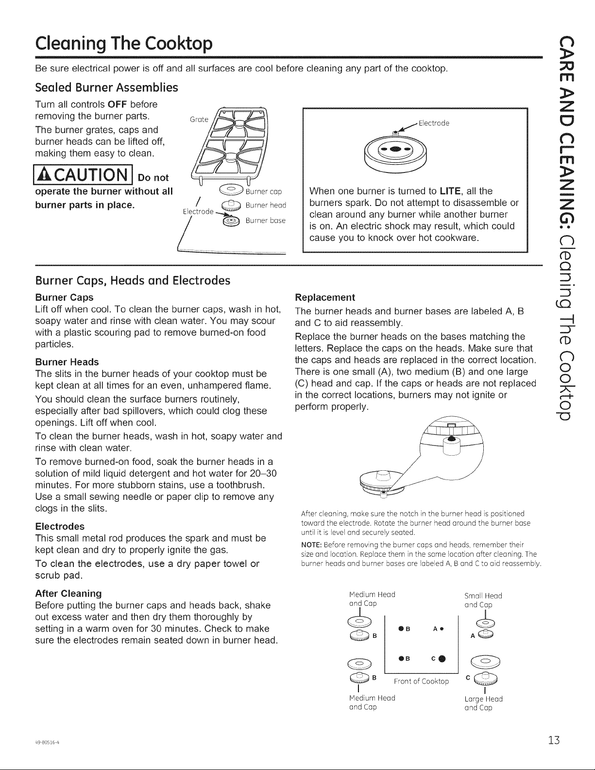
Sealed Burner Assemblies
Turn all controls OFF before
removing the burner parts.
The burner grates, caps and
burner heads can be lifted off,
making them easy to clean.
[,&CAUTION] Donor
operate the burner without all
burner parts in place.
Burner Caps, Heads and Electrodes
Burner Caps
Lift off when cool. To clean the burner caps, wash in hot,
soapy water and rinse with clean water. You may scour
with a plastic scouring pad to remove burned-on food
particles.
Burner Heads
The slits in the burner heads of your cooktop must be
kept clean at all times for an even, unhampered flame.
You should clean the surface burners routinely,
especially after bad spillovers, which could clog these
openings. Lift off when cool.
To clean the burner heads, wash in hot, soapy water and
rinse with clean water.
To remove burned-on food, soak the burner heads in a
solution of mild liquid detergent and hot water for 20-30
minutes. For more stubborn stains, use a toothbrush.
Use a small sewing needle or paper clip to remove any
clogs in the slits.
Electrodes
This small metal rod produces the spark and must be
kept clean and dry to properly ignite the gas.
To clean the electrodes, use a dry paper towel or
scrub pad.
Grate/
ctrode
_cap
When one burner is turned to LITE, all the
burners spark. Do not attempt to disassemble or
clean around any burner while another burner
is on. An electric shock may result, which could
cause you to knock over hot cookware.
Replacement
The burner heads and burner bases are labeled A, B
and C to aid reassembly.
Replace the burner heads on the bases matching the
letters. Replace the caps on the heads. Make sure that
the caps and heads are replaced in the correct location.
There is one small (A), two medium (B) and one large
(C) head and cap. If the caps or heads are not replaced
in the correct locations, burners may not ignite or
perform properly.
After cleaning, make sure the notch in the burner head is positioned
toward the electrode. Rotate the burner head around the burner base
until it is level and securely seated.
NOTE: Before removing the burner caps and heads, remember their
size and location. Replace them in the same location after cleaning. The
burner heads and burner bases are labeled A, B and C to aid reassembly.
m
N
m
Z
!
@ @
n
CD
C3
_D
---4
Z3-
CD
Ch
O
O
O
-O
After Cleaning
Before putting the burner caps and heads back, shake
out excess water and then dry them thoroughly by
setting in a warm oven for 30 minutes. Check to make
sure the electrodes remain seated down in burner head.
Medium Head Small Head
P and Ca_
OB Ae
@B AQ
B
FrontofCooktop c ._
I I
Medium Head Large Head
and Cap and Cap
Page 14
CL
O
,,,f
O
O
U
(D
c-
F--
O7
c-
C
E3
(b
U
Z
!
Z
<I:
-,J
U
a
Z
<1:
t_
<1:
U
Cleaning The Cooktop
Burner Grates, Vent Grille and Gasket
Lift off when cool. Grates, grille and gasket should be
washed regularly and, of course, after spillovers.
To clean, wash them in hot, soapy water and rinse with
clean water.
Discoloration on the grates may also be removed by
using the provided cooktop cleaning cream. Apply a drop
or two on a damp cloth and rub across the discolored
area. Rinse and dry. After cleaning, replace the burner
grates and make sure they are positioned securely over
the burners.
To remove burned-on food,
use a soap-filled scouring pad.
Although they are durable, the
grates will gradually lose their
shine, regardless of the best
care you can give them. This is
due to their continual exposure
to high temperatures. You will
notice this sooner with lighter
color grates.
Do not operate a burner for
an extended period of time
without cookware on the
burner grate. The finish on
the grate may chip without
cookware to absorb the heat.
Vent Filter and Chamber
Appearance may vary.
The grate legs have four rubber
feet. To order replacement rubber
grate feet, see the Assistance /
Parts and Accessories section.
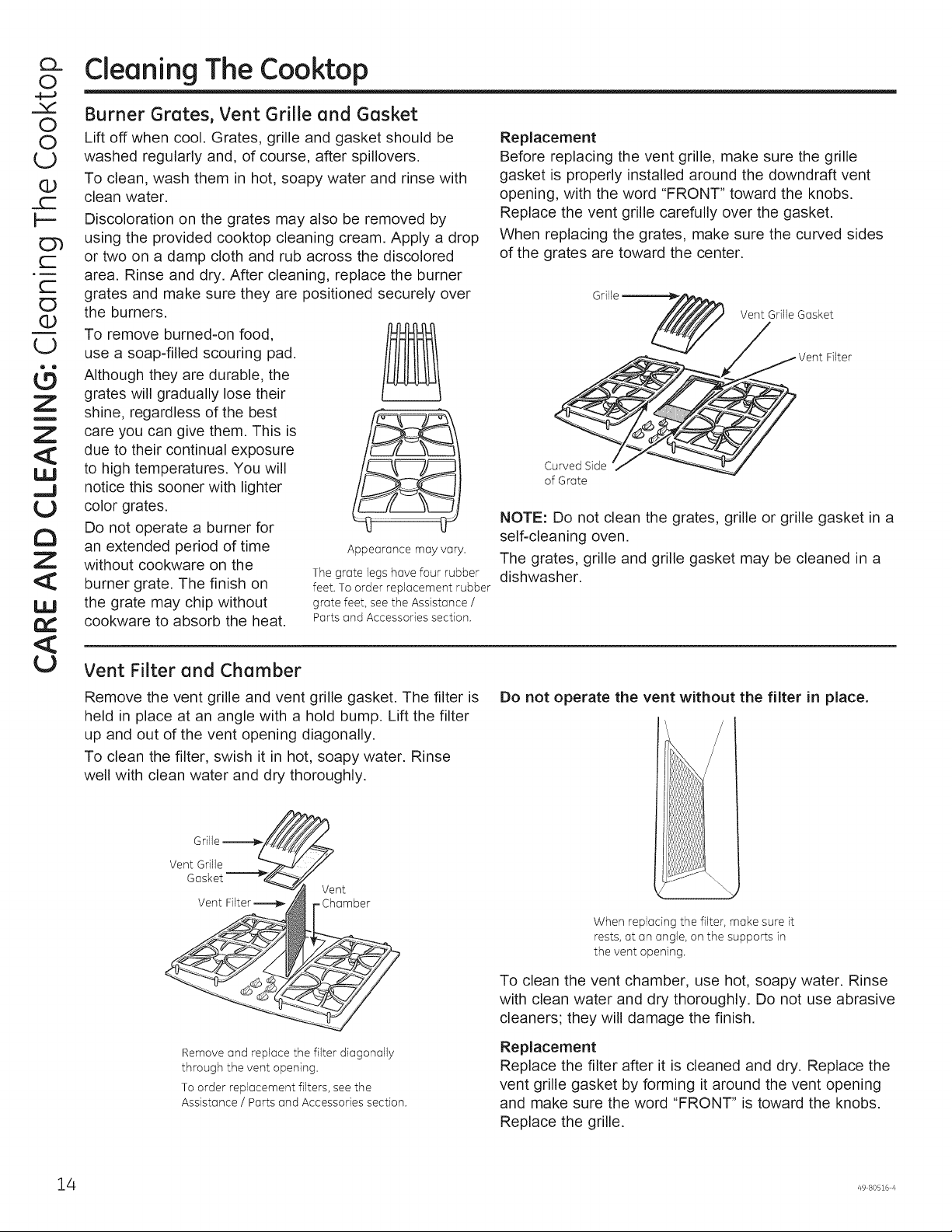
Replacement
Before replacing the vent grille, make sure the grille
gasket is properly installed around the downdraft vent
opening, with the word "FRONT" toward the knobs.
Replace the vent grille carefully over the gasket.
When replacing the grates, make sure the curved sides
of the grates are toward the center.
Vent Grille Gasket
Curved Side
of Grate
NOTE: Do not clean the grates, grille or grille gasket in a
self-cleaning oven.
The grates, grille and grille gasket may be cleaned in a
dishwasher.
Remove the vent grille and vent grille gasket. The filter is
held in place at an angle with a hold bump. Lift the filter
up and out of the vent opening diagonally.
To clean the filter, swish it in hot, soapy water. Rinse
well with clean water and dry thoroughly.
Vent
Chamber
Remove and replace the filter diagonally
through the vent opening.
To order replacement filters, see the
Assistance / Parts and Accessories section.
Do not operate the vent without the filter in place.
When replacing the filter, make sure it
rests, at an angle, on the supports in
the vent opening.
To clean the vent chamber, use hot, soapy water. Rinse
with clean water and dry thoroughly. Do not use abrasive
cleaners; they will damage the finish.
Replacement
Replace the filter after it is cleaned and dry. Replace the
vent grille gasket by forming it around the vent opening
and make sure the word "FRONT" is toward the knobs.
Replace the grille.
4 49 80516 4
Page 15
Cleaning The Cooktop
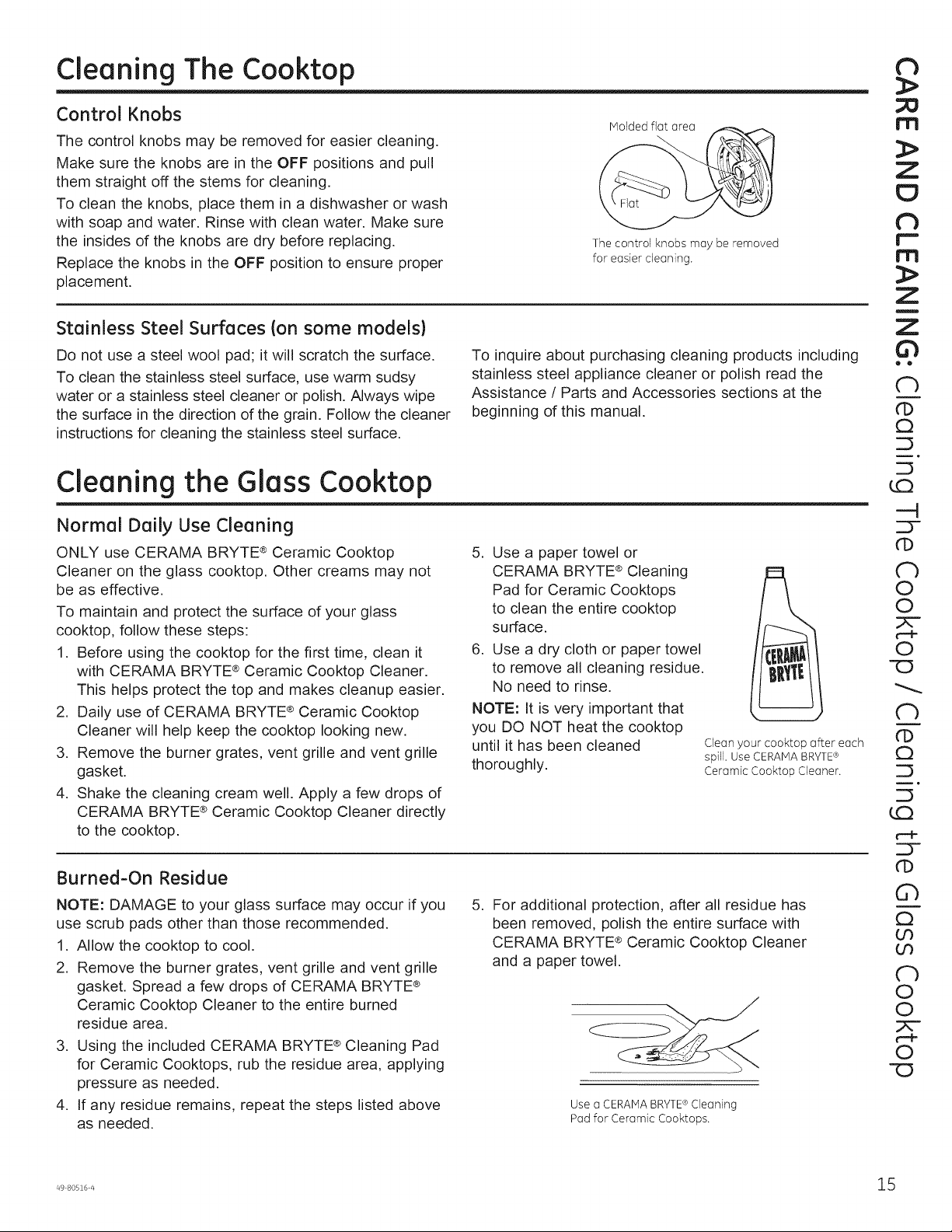
Control Knobs
The control knobs may be removed for easier cleaning.
Make sure the knobs are in the OFF positions and pull
them straight off the stems for cleaning.
To clean the knobs, place them in a dishwasher or wash
with soap and water. Rinse with clean water. Make sure
the insides of the knobs are dry before replacing.
Replace the knobs in the OFF position to ensure proper
placement.
Stainless Steel Surfaces (on some models)
Molded flat area
The control knobs may be removed
for easier cleaning.
th
:1>
I'TI
:I>
th
r'-
I"1"1
:1>
Z
!
Do not use a steel wool pad; it will scratch the surface.
To clean the stainless steel surface, use warm sudsy
water or a stainless steel cleaner or polish. Always wipe
the surface in the direction of the grain. Follow the cleaner
instructions for cleaning the stainless steel surface.
Cleaning the Glass Cooktop
Normal Daily Use Cleaning
ONLY use CERAMA BRYTE ®Ceramic Cooktop
Cleaner on the glass cooktop. Other creams may not
be as effective.
To maintain and protect the surface of your glass
cooktop, follow these steps:
1. Before using the cooktop for the first time, clean it
with CERAMA BRYTE ®Ceramic Cooktop Cleaner.
This helps protect the top and makes cleanup easier.
2. Daily use of CERAMA BRYTE ®Ceramic Cooktop
Cleaner will help keep the cooktop looking new.
3. Remove the burner grates, vent grille and vent grille
gasket.
4. Shake the cleaning cream well. Apply a few drops of
CERAMA BRYTE ® Ceramic Cooktop Cleaner directly
to the cooktop.
To inquire about purchasing cleaning products including
stainless steel appliance cleaner or polish read the
Assistance / Parts and Accessories sections at the
beginning of this manual.
5. Use a paper towel or
CERAMA BRYTE ® Cleaning
Pad for Ceramic Cooktops
to clean the entire cooktop
surface.
6. Use a dry cloth or paper towel
to remove all cleaning residue.
No need to rinse.
NOTE: It is very important that
you DO NOT heat the cooktop
until it has been cleaned
thoroughly.
Clean your cooktop after each
spill. Use CERAMABRYTE®
Ceramic Cooktop Cleaner.
ii •
Cb
CD
Q
CD
O
©
©
-O
N
CD
Q
r_
Burned-On Residue
NOTE: DAMAGE to your glass surface may occur if you
use scrub pads other than those recommended.
1. Allow the cooktop to cool.
2. Remove the burner grates, vent grille and vent grille
gasket. Spread a few drops of CERAMA BRYTE ®
Ceramic Cooktop Cleaner to the entire burned
residue area.
3. Using the included CERAMA BRYTE ®Cleaning Pad
for Ceramic Cooktops, rub the residue area, applying
pressure as needed.
4. If any residue remains, repeat the steps listed above
as needed.
,
For additional protection, after all residue has
been removed, polish the entire surface with
CERAMA BRYTE ® Ceramic Cooktop Cleaner
and a paper towel.
Use a CERAMABRYTE Cleaning
Pad for Ceramic Cooktops.
®
CD
Q
N
©
O
©
-O
Page 16
o_
O
.._hal
O
O
U
Or)
or)
E_
LO
(D
t--
Oh
t--
r---
E3
(b
U
G
Z
!
Z
<I:
,,,,J
!,3
a
Z
<1:
I,,IJ
rY
<1:
Ij
Cleaning the Glass Cooktop
Heavy, Burned-On Residue
I. Allow the cooktop to cool.
2. Remove the burner grates, vent grille and vent grille
gasket.
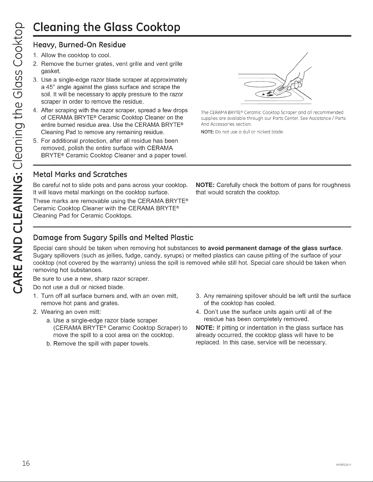
3. Use a single-edge razor blade scraper at approximately
a 45 ° angle against the glass surface and scrape the
soil. It will be necessary to apply pressure to the razor
scraper in order to remove the residue.
4. After scraping with the razor scraper, spread a few drops
of CERAMA BRYTE®Ceramic Cooktop Cleaner on the
entire burned residue area. Use the CERAMA BRYTE®
Cleaning Pad to remove any remaining residue.
5. For additional protection, after all residue has been
removed, polish the entire surface with CERAMA
BRYTE ®Ceramic Cooktop Cleaner and a paper towel.
Metal Marks and Scratches
Be careful not to slide pots and pans across your cooktop.
It will leave metal markings on the cooktop surface.
These marks are removable using the CERAMA BRYTE ®
Ceramic Cooktop Cleaner with the CERAMA BRYTE ®
Cleaning Pad for Ceramic Cooktops.
Damage from Sugary Spills and Melted Plastic
Special care should be taken when removing hot substances to avoid permanent damage of the glass surface.
Sugary spillovers (such as jellies, fudge, candy, syrups) or melted plastics can cause pitting of the surface of your
cooktop (not covered by the warranty) unless the spill is removed while still hot. Special care should be taken when
removing hot substances.
Be sure to use a new, sharp razor scraper.
Do not use a dull or nicked blade.
1. Turn off all surface burners and, with an oven mitt,
remove hot pans and grates.
2. Wearing an oven mitt:
a. Use a single-edge razor blade scraper
(CERAMA BRYTE®Ceramic Cooktop Scraper) to
move the spill to a cool area on the cooktop.
b. Remove the spill with paper towels.
The CERAIV]ABRYTE®Ceramic Cooktop Scraper and all recommended
supplies are available through our Parts Center. See Assistance / Parts
And Accessories section.
NOTE: Do not use a dull or nicked blade.
NOTE: Carefully check the bottom of pans for roughness
that would scratch the cooktop.
3. Any remaining spillover should be left until the surface
of the cooktop has cooled.
4. Don't use the surface units again until all of the
residue has been completely removed.
NOTE: If pitting or indentation in the glass surface has
already occurred, the cooktop glass will have to be
replaced. In this case, service will be necessary.
16 49 80516 4
Page 17
I stallatio
GasDowndraft Cooktop
!
Z
¢/}
I structios
r_ ,,if you have questions, call 800.GE.CARES or visit our website at GEAppliances.com
IN THE COMMONWEALTH OF MASSACHUSETTS:
• This product must be installed by a licensed plumber or
gas fitter.
• When using ball-type gas shut-off valves, they shall be
the T-handle type.
• A flexible gas connector, when used, must not exceed
5 feet.
BEFORE YOU BEGIN
Read these instructions completely and carefully.
•INPORTANT- savetheseinstructionsforlocal
inspector's use.
•IN PORTANT - Observeallgoverning codes
and ordinances.
• Note to Installer - Be sure to leave these instructions
with the Consumer.
• Note to Consumer - Keep these instructions for future
reference.
• Unlessvery knowledgeable in the installation of this
product, engage a professional installer.
• Proper installation is the responsibility of the installer.
• Product failure due to improper installation is not
covered under the Warranty.
FOR YOUR SAFETY
If You SmellGas:
1.Openwindows.
2. Don't touch any electrical switches.
3. Extinguish any open flame.
4. Immediately call your gas supplier.
Do not store or use gasoline or other flammable vapors
and liquids in the vicinity of this or any other appliance.
PGP9830
TOOLS AND MATERIALS YOU WILL NEED
• Saw
° Ducttape
° Measuringtape or scale
° Carpenter's square
° Adjustable wrench or socket set (:/16"socketand ratchet)
° Drilland drill bit
• V4"nut driver
• Sheetmetal screws
• Pipewrench
• Manual gas lineshut-offvalve
• Pipejoint sealant that resistsaction of LPgas
• Ductwork to suit the installation
For rigid connection:
• Shut-off valve
• Union
• Pipefittings as required
Forflexible connection where local codes permit:
• Flexiblemetal tubing (same s/4"or_/2"I.D.as gas
supply line)
HIGH ALTITUDE ORIFICE CONVERSION KIT
use for cooktop operation at elevations above 5000 ft.
(1500m).
Specifykit for Natural Gasor LPGas when ordering:
Natural GasHighAltitude
OrificeConversionKit........................ WB28X10114
LPHighAltitudeOrificeConversionKit ....... WB28X10115
Toorder, pleasecall our toll-free number:
National Parts Center ............. 800.626.2002
r'-
!
O
Z
!
Z
¢D
--I
C
d_
--I
!
O
Z
A WARNING - Beforebeginning the installation,
switch power off at the service panel and lock the service
disconnecting means to prevent power from being switched
on accidentally.When the servicedisconnecting means
cannot be locked, securelyfasten a prominent warning
device,suchas a tag, to the servicepanel.
Page 18
Z
0
i
I--
U
::)
l--
Z
u
Z
0
g
_u
_u
Z
i
Installation Instructions
IMPORTANT SAFETY INSTRUCTIONS
IX PORTANT SAFETY INSTRUCTIONS
Thecooktop hasbeen design certified by Underwriters
Laboratories (UL).Aswith any appliance usinggas and
generating heat,there are certain safety precautions you
should follow. You'llfind these precautions in the Important
SafetyInformationsection in the front of this Owner's Manual.
Readthem carefully.
• Besureyour cooktop is installed properly by a qualified
installer or servicetechnician.
• Thecooktop must be electrically grounded in accordance
with localcodes,or intheir absence, with the National
ElectricalCodeANSI/NFPANo. 70 - LatestEdition.
• Installation ofthis cooktop must conform with local codes,
or in the absence of local codes,with the National FuelGas
CodeANSIZ223.1/NFPA54- LatestEdition.
• Improper installation, adjustment, alteration, serviceor
maintenance can cause injury or property damage. Referto
this manual. Forassistanceor additional information, consult
a qualified installer,service agency,manufacturer (dealer)or
the gas supplier.
• Disconnectelectricalsupply beforeservicing.
• Neverreuseold flexible connectors.Theuse of oldflexible
connectors can cause gas leaksand personal injury.Always
use NEWflexibleconnectorswhen installing agas appliance.
• Makesurethe wall coverings around the cooktop can
withstand heat generated bythe cooktop up to 200°F.
• Avoid placingcabinets above the cooktop.
• Ifcabinets are placedabove the cooktop, allow a minimum
clearance of 30"betweenthe cooking surface and the
bottom of unprotected cabinets.
• Ifcabinets are placedabove the cooktop, use cabinets no
more than 13"deep.
• Ifa 30" clearance between cooking surfaceand overhead
combustible material or metalcabinets cannot be
maintained, protect the undersideof the cabinetsabove
the cooktop with not lessthan 1/4"insulating millboard or
gypsum boardat least s/16"thick covered with 28 gauge
sheet steel or 0.020"thick copper.
• Clearance between the cooking surface and protected
cabinets MUSTNEVERBELESSTHAN 24" Thevertical
distance from the plane ofthe cooking surface to the bottorr
of adjacent overhead cabinets extending closerthan 1" to
the planeofthe cooktop sides must not belessthan 18".
EXHAUST BLOWER RATINGS
EXHAUST BLOWER SAFETYWARNING
Sufficient air isneededfor proper combustion and exhausting of gasesthrough the flue (chimney)offuel burning equipment to
prevent back drafting. Followthe heating equipment manufacturer's guide linesand safety standards, such as those published by
the National FireProtection Association (NFPA),the American Society for Heating, Refrigeration and Air Conditioning (ASHRAE)and
the localcode authorities, when applicable, install any make up (replacement)air system in accordance with localbuilding code
requirements.Visit GEAppliances.comfor available makeup air solutions.
8 49 80516 4
Page 19
Installation Instructions
PARTS INCLUDED
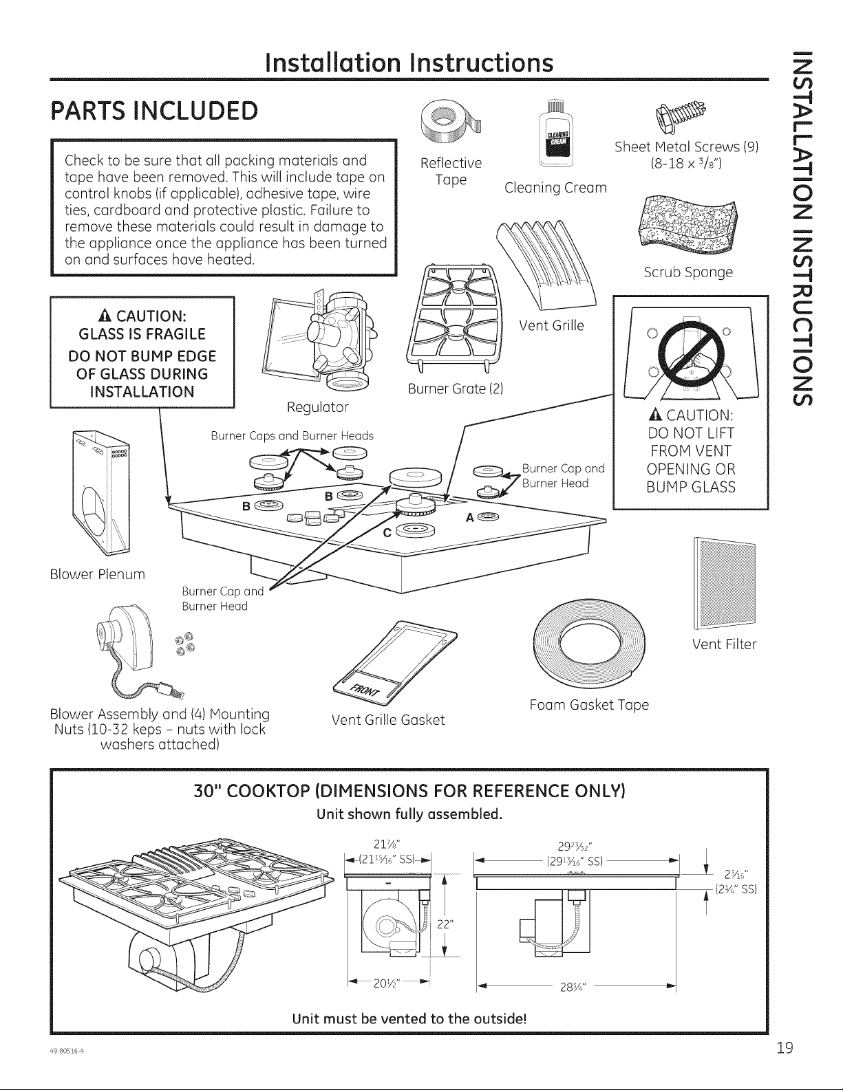
Check to be sure that all packing materials and
tape have been removed. Thiswill include tape on
control knobs (if applicable), adhesive tape, wire
ties, cardboard and protective plastic. Failure to
remove these materials could result in damage to
the appliance once the appliance has been turned
on and surfaces have heated.
Reflective
Tape
Cleaning Cream
!
Z
Sheet Metal Screws (9)
(8-18 x s/s")
!
0
Z
!
Z
Scrub Sponge
CAUTION:
GLASS IS FRAGILE
DO NOT BUMP EDGE
OF GLASS DURING
INSTALLATION
Burner Caps and Burner Heads
Blower Plenum
Burner Cap and
Burner Head
Blower Assembly and (4) Mounting
Nuts (10-32 keps - nuts with lock
washers attached)
Regulator
Vent Grille Gasket
Burner Grate (2)
A®
Vent Grille
Burner Cap and
Head
,,!<!
Foam Gasket Tape
C
d_
!
0
Z
A CAUTION:
DO NOT LIFT
FROM VENT
OPENING OR
BUMP GLASS
Vent Filter
30" COOKTOP (DIMENSIONS FOR REFERENCE ONLY)
Unit shown fully assembled.
201/2''
Unit must be vented to the outside!
28sA''
Page 20
Z
O
i
I-.
U
=)
!-.
Z
u
Z
O
g
Installation Instructions
CABINET PREPARATION
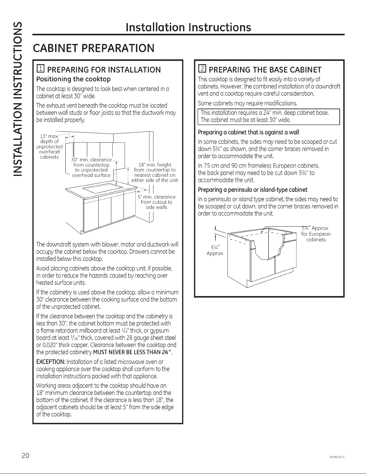
ITI PREPARING FOR INSTALLATION
Positioning the cooktop
Thecooktop isdesignedto look best when centered in a
cabinet at least 50"wide.
Theexhaust vent beneath the cooktop must be located
between wall studs or floor joists sothat the ductwork may
be installed properly.
[_ PREPARING THE BASE CABINET
Thiscooktop isdesigned to fit easilyinto a variety of
cabinets. However,the combined installation of a downdraft
vent and a cooktop require careful consideration.
Somecabinets may require modifications.
Thecabinet must be at least 30" wide.
i This installation requiresa24" min.deep cabinet base.
_u
_u
Z
i
13"max:-- _L-I
depth of ___._,
unprotected I IJ I
overhead I II I
cabinets I "'^ • , '
Thedowndraft system with blower, motor and ductwork will
occupy the cabinet below the cooktop. Drawers cannot be
installed belowthis cooktop.
Avoid placing cabinets abovethe cooktop unit, if possible,
in order to reducethe hazards caused by reaching over
heated surface units.
Ifthe cabinetry is usedabovethe cooktop, allow a minimum
30" clearance between the cooking surface and the bottom
of the unprotected cabinet.
Ifthe clearance between the cooktop and the cabinetry is
lessthan 30",the cabinet bottom must be protected with
a flame retardant millboard at least 1/4"thick, or gypsum
board at least s/16"thick, covered with 28 gauge sheetsteel
or 0.020"thick copper. Clearancebetween the cooktop and
the protected cabinetry MUSTNEVERBELESSTHAN24".
EXCEPTION:Installationof a listed microwave oven or
cooking appliance overthe cooktop shallconform to the
installation instructions packed with that appliance.
Working areasadjacent to the cooktop should have an
18"minimum clearance between the countertop and the
bottom of the cabinet. Ifthe clearanceislessthan 18",the
adjacent cabinets should be at least 5" from the side edge
of the cooktop.
I 4u" mln. clearance
/from countertop
/ to unprotected
_" overhead surface
18" min. height
from countertop to
nearest cabinet on
either side of the unit
5" min. clearance
from cutout to
side walls
Preparing a cabinet that is against a wall
Insome cabinets,the sides may needto be scooped or cut
down 5sA" as shown, andthe corner braces removed in
order to accommodate the unit.
In 75 cm and 90 cm frameless European cabinets,
the back panel may need to be cut down 5sA"to
accommodate the unit.
Preparing a peninsula or island-type cabinet
In a peninsulaor islandtype cabinet,the sides may need to
be scooped or cut down, andthe corner braces removed in
order to accommodate the unit.
5:Y_' Approx.
for European
cabinets
5%"
Approx.
0 49 80516 4
Page 21
Installation Instructions
CABINET PREPARATION CUTOUTS
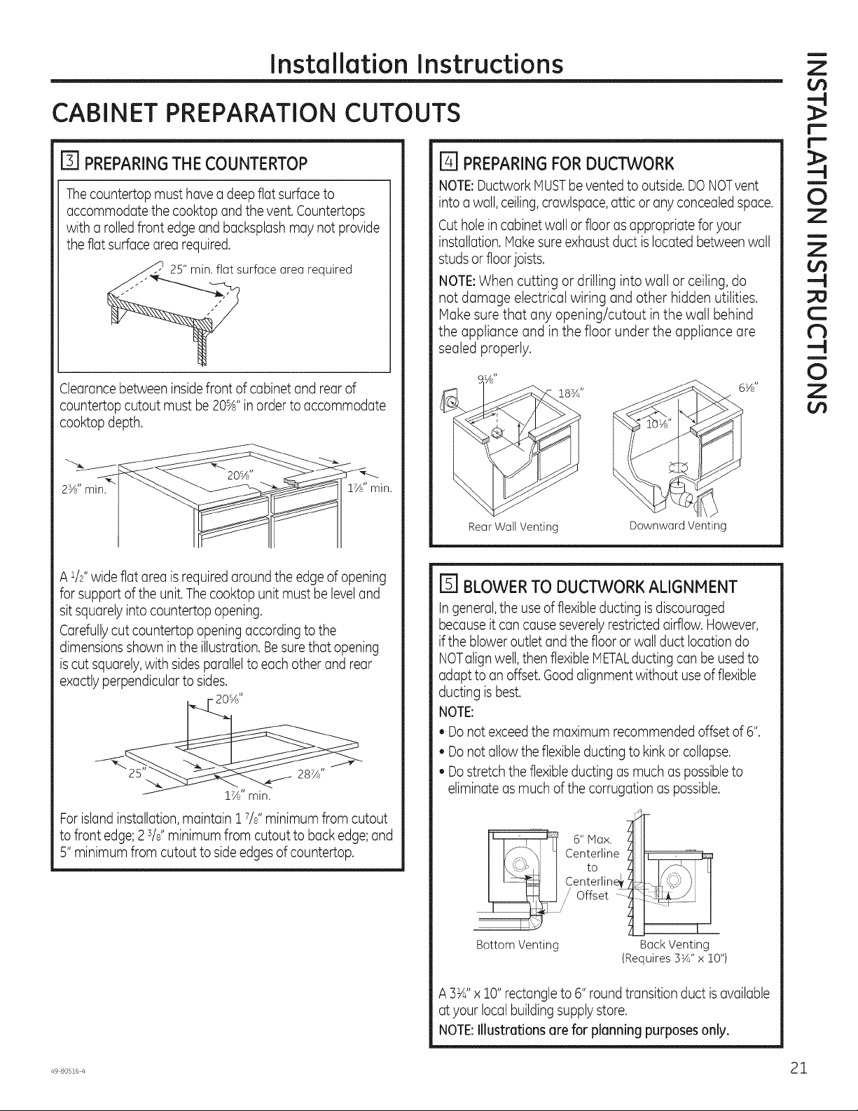
FI PREPARING THE COUNTERTOP
Thecountertop must have a deep flat surface to
accommodate the cooktop and the vent.Countertops
with a rolled front edgeand backsplash may not provide
the flat surface area required.
25" min. flat surface area required
Clearance between insidefront of cabinet and rear of
countertop cutout must be 20sA"inorderto accommodate
cooktop depth.
E] PREPARING FOR DUCTWORK
NOTE:Ductwork MUSTbevented to outside. DONOTvent
into a wall,ceiling,crawlspace, attic or any concealed space.
Cut hole in cabinet wall or floor as appropriate for your
installation. Make sureexhaust duct is located between wall
studsor floorjoists.
NOTE:When cutting or drilling into walt or ceiling, do
not damage electrical wiring and other hidden utilities.
Make sure that any opening/cutout in the wait behind
the appliance and in the floor under the appliance are
sealed properly.
183A ''
!
Z
r"-
i"-
!
0
Z
!
Z
¢/3
--I
C
db
--I
!
0
Z
2sA'' min.
A 1/Z'wide flat area is required around the edge of opening
for support ofthe unit.The cooktop unit must be level and
sit squarely into countertop opening.
Carefullycut countertop opening accordingto the
dimensions shown in the illustration. Besure that opening
iscut squarely,with sides parallelto each other and rear
exactly perpendicular to sides.
20%"
17/8"min.
Forislandinstallation, maintain 1W' minimum from cutout
to front edge;2W' minimum from cutout to back edge;and
5"minimum from cutout to side edgesof countertop.
1_" min.
Rear Wall Venting Downward Venting
E] BLOWERTO DUCTWORKALIGNMENT
Ingeneral,the useofflexible ducting isdiscouraged
because it can cause severelyrestricted airflow. However,
ifthe blower outlet and the floor or wall duct location do
NOTalign well,then flexible METALducting can be used to
adapt to an offset. Goodalignment without useof flexible
ducting isbest.
NOTE:
• Donot exceed the maximum recommended offset of 6".
• Donot allow the flexibleducting to kinkor collapse.
• Dostretchthe flexibleducting as much as possibleto
eliminate as much ofthe corrugation as possible.
6"max.
Centerline _ i_
Cen_°rlin_4_'_ J
....,,,,,Offset ......_ 1 ._=_
BottomVenting BackVenting
A 3_4"x !0" rectangle to 6" round transition duct is available
at your local building supply store.
NOTE:Illustrations are for planning purposes only.
(Requires3_/4"x 10")
Page 22
Z
0
i
I-.
U
=)
!-.
Z
u
Z
0
g
_J
_J
Z
i
Installation Instructions
DESIGN INFORMATION
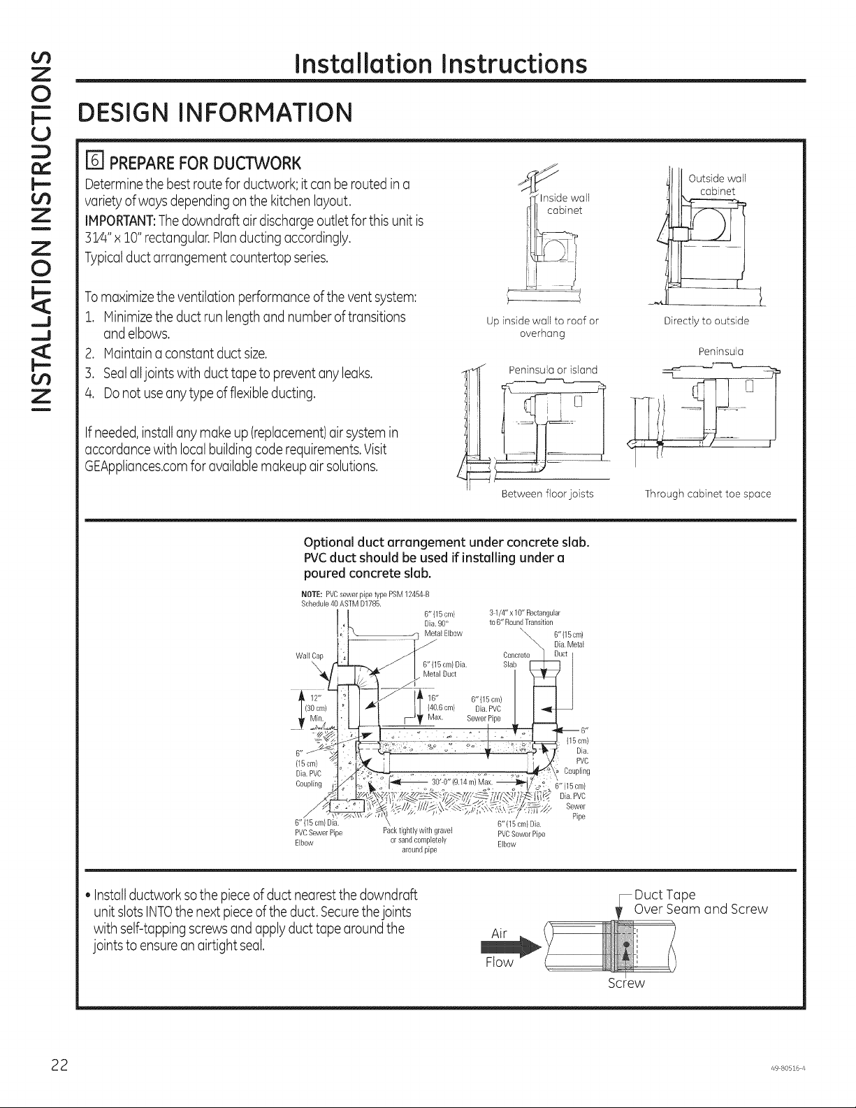
E] PREPARE FOR DUCTWORK
Determinethe best route for ductwork; it can berouted in a
variety of ways depending on the kitchen layout.
IMPORTANT:Thedowndraft air discharge outlet for this unit is
3:1/4"x 10"rectangular.Planducting accordingly.
Typicalductarrangement countertop series.
Tomaximizetheventilationperformanceoftheventsystem:
1. IVlinimizetheductrunlengthandnumberoftransitions
andelbows.
2. Maintainaconstantductsize.
]. Sealalljointswithducttapetopreventanyleaks.
4. Donot useanytypeofflexibleducting.
Inside wall
cabinet
Up inside wall to roof or
overhang
Outside wall
cabinet
Directly to outside
Peninsula
Ifneeded,installanymakeup(replacement)airsystemin
accordancewith localbuildingcoderequirements.Visit
GEAppliances.comforavailablemakeupairsolutions.
Optional duct arrangement under concrete slab.
PVCduct should be used if installing under a
poured concrete slab.
NOTE: PVCsewer pipetype PSM12454B
Schedule40ASTM D1785.
wa,,Pep ::ete
6"
(15cm}
Dia. PVC
Coupling
6" (15 cm) Dia.
PVCSewerPipe Packtightlywith gravel
Elbow orsand completely
i Peninsula or island
Between floor joists Through cabinet toe space
6"{15 cm)
Dia. 90°
Metal Elbow \,_
Metal Duct X_
3-1/4"x 1O"Rectangular
to 6" RoundTransition
II I_O._cm/D_a.PV6I I"
oo _t_6"(15cm/
6" (15 cm) Dia.
PVCSewer Pipe
aroundpipe
Elbow
6"{15 cm)
Die.Metal
115cer}
Dia.
PVC
Coupling
i_ Dia. PVC
Sewer
Pipe
6"
• Installductwork sothe pieceof duct nearest the downdraft
unit slots INTOthe next pieceof the duct. Securethejoints
with self-tapping screws and apply ducttape aroundthe
Air
_DuctTape
_Over Seam and Screw
joints to ensurean airtight seal.
2 49 80516 Z_
Page 23

Installation Instructions
POWER SUPPLY LOCATIONS
E] GAS SUPPLY:
Thesecooktops are designed to operate on natural gas at
4" of water column pressure or on LPgas at 10" ofwater
column pressure.
• Thesecooktops are shipped from the factory set for
natural gas.Ifyou decideto usethis cooktop with LP
gas,conversion adjustments must be made bya service
technician or other qualified person.
• The pressureregulator must be connected in serieswith
the manifold of the cooktop and must remain in series
with the supply line regardless of type of gas being used.
Forproper operation, the maximum inlet pressure to
the regulator must be no more than 10"water column
pressure for natural gas and 14"water column pressure
for LPgas.
• When checking the regulator, the inlet pressure must be
at least 1"greater than the regulator output setting. If
the regulator is set for 4" of water column pressure, the
inlet pressure must be at least 5".If the regulator is set
for 10"of water column pressure,the inlet pressuremust
be at least 11".For ease of installation, and if local codes
permit, the gas supply line into the cooktop should be 1/2"
or W' IDflexible metal appliance connector, three to five
feet long.
NOTE:Purchasea newflexible line. DONOTUSEAN OLD
PREVIOUSLYUSEDLINE.
• Hake gas connection through rear wall, oron cabinet floor
at rear,as illustrated.
r_ ELECTRICALSUPPLY:
I
Electrical
outlet !2"
above cabinet
floor (mount
on side or
back cabinet
wall 2"min.
from
centerline)
4" (to clear toe kick area)
Thebuilt-in gas downdraft cooktop features pilotlesselectric
ignition for energy savingsand reliability.It operateson a
120-volt,60-Hz power supply.A separate circuit, protected
by a 1S-amptime-delay fuse or circuit breaker, is required.
• A properly grounded 3-prong receptacle should be located
within reach of cooktop's four foot power cord.
IMPORTANT:(Pleaseread carefully.} FORPERSONAL
SAFETY,THISAPPLIANCEMUSTBEPROPERLYGROUNDED.
Thepower cord of this appliance is equipped with a
three-prong (grounding)plug which mates with a standard
three-prong grounding wall receptacle to minimizethe
possibilityof electric shock hazardfrom this appliance.
Thecustomershould have the wall receptacle and circuit
checked by a qualified electrician to make sure the
receptacle is properly grounded and hascorrect polarity.
Where a standard two-prong wall receptacleis
encountered, it isthe personal responsibilityand obligation
of the customer to have it replaced with a properly
grounded three-prong wall receptacle.
Do Not, Under Any Circumstances, Cut Or Remove The
Third (ground} Prong From ThePower Cord,
Do not use an extension cord,
!
Z
¢D
r'-
r'-
!
O
Z
!
Z
--I
C
-4
!
O
Z
Page 24

¢D
Z
0
i
I--
U
::)
cx:
I--
¢D
Z
u
Z
0
g
_u
_u
¢D
Z
i
Installation Instructions
UNPACKING THE COOKTOP/INSTALLING THE GASKET
E] INSTALLINGTHE FOAMGASKETAND
REFLECTIVETAPE
A CAUTION:Potential riskof fire- reflective tape
must besecured around countertop opening as shown.
Donot installthe cooktop into the countertop without
installingthe foam gasket asshown. It protects the bottom
edge ofthe glassfrom the countertop and sealsthe cooktop
against spills.
Removethe cooktop along with itsshipping pad from
the shipping box. Removethe shipping blockfrom the
downdraft vent opening and place it under the shipping pad
to provide level support.
Foam Gasket Installation Notes:
• Thefoam gasket tape should be installed within 1/8"of
the edge of the glass. Donot stretch or twist the foam
gasket tape.
A CAUTION:FaiUureto install foam gasket tape
greatly increases the potential of breaking the cooktop
glass when installing, especially in Corian®or granite
countertops.
• Usecare not to stretch the foam gasket tape while it is
installedor it will not stay in place.
• Donot place foam gasket tape over the metal flanges.
• Butthe foam gasket tape ends together at each corner
without overlapping.
• Trim the foam gaskettape to length without stretching.
• Hitre cut outside cornersof foam gaskettape slightly if
necessaryfor appearance.
Center vent shipping block -
place under the shipping pad to
provide level support
^_ CAUTION:GLASS ISFRAGILE.DO NOT BUMP
EDGE OF GLASS DURING INSTALLATION.
Locatethe reflectivetape and foam gasket tape included
with your cooktop.
Smooth rough edges of the cutout. Installreflectivetape to
the opening,along the inside and s/8"to 1/2"of the opening
edge.
Place reflective tape
within i/2" of cutout
Reflective tapetop
and vertical sides
Foam
Gasket
Tape
v_"max.to
GlassEdge
• Donotscratch the glasswhile cutting thefoam gaskettape.
Peeloff the white backing to install the foam gasket tape on
the bottom side of the cooktop glassas shown.
4 49 80516 Z_
Page 25

Installation Instructions
INSTALLING THE COOKTOP
rio] INSTALLINGTHECOOKTOP:
,_ CAUTION:
DO NOT LIFT FROM
VENT OPENING.
ri_ INSTALLING THE OPTIONAL
INSTALLATION BRACKETS
NOTE:Checkfor glassflatnessin Step9 beforeinstalling
optionalinstallationbrackets.
!
Z
r"
r-
!
O
Z
!
Z
Liftthe cooktop by the glass sideedgesas shown.
NOTE:Donot usethe glasstop vent opening to lift or move
the cooktop into position.
\
Lowerthe cooktop into the countertop opening,guiding it
into position. Glassisfragile-do not allow itto drop onto the
countertop. Support from the undersideand lower slowly.
Carefullyremoveyour fingers one corner at a time to lower
the cooktop into position.
NOTE:Do not useSilicone RTVor caulk to bondcooktop
glass to countertop.
Oncethe unit isplaced in countertop; visually inspect the
cooktop and counter,appearance or alignment concerns.
Optional installation
/ bracket and thumb
screw (not included)
!
Cooktop L__Cou ntertop
Screwssupplied with _._____
cooktop Thumbscrew
Toorder optional installationbrackets/thumbscrews,callthe
NationalPartsCenterat 800.626.2002.
Ordertwo of eachpart:WB02XZZ351Bracket
WB01X10353Screw
Toinstalloptionalinstallationbrackets:
Remove2screwson bothsidesunder cooktop.
Alignoptionalinstallationbracketunder cooktopandreinstall
screwsthrough the slot inthe bracket.Dothis on bothsidesof
thecooktop.
Threadthe thumb screwthroughthe holein the bracketand
tightento securethe cooktop to thecountertop.Repeatonthe
otherside.
IHPORTANT:Turnthumb screwuntilittouchesthe bottom of
thecountertop.Do notovertighten.
--I
C
db
--I
!
O
Z
Page 26

Z
0
i
I--
U
::)
cx:
l--
Z
u
Z
0
g
_J
_J
Z
i
Installation Instructions
INSTALLING THE COOKTOP
r_ INSTALLINGTHEBLOWERPLENUH
TOTHECOOKTOP
Slidethe plenum, with the blower openingon the left, into
the openingin the bottom of the cooktop. Pushup on the
plenum until the stops on the plenum contact the bottom of
the cooktop,andsnap the plenum into place.(Youmay have
to movethe plenum back and forth to work it into place.)
" _tnstall2screws
r_ INSTALLINGTHE BLOWER
TO THEPLENUH
Orientthe blower discharge opening to match the ductwork
in Steps5 and 6. Slidethe four threaded studs on the side
of the blower housing into the four holeson the side ofthe
plenum.
NOTE:SeeStep 13for installingthe transition duct to the
blower. It may be easier to installthe transition duct to the
blower before installing the blowerto the plenum.
Install 4 screws
Securethe plenum to the bottom of the cooktop, on each
side, usingthe four (4)screws provided.Further secure the
plenum to the cooktop, from the top side,usingthe two
screws (2)provided.
From the vent opening in the top of the cooktop, fasten the
blower assembly securelyto the plenumwith four (4)nuts.
4 Nuts
(7/1¢
socket
required)
6 49 80516 4
Page 27

Installation Instructions
INSTALLING THE COOKTOP
!
Z
r_] ATTACHINGA BLOWER
TRANSITIONDUCT
Usea blower transition duct for alldownward duct
installationsto connect to 6" round standard ductwork. This
3_4"x 10" rectangle to 6" round transition duct is availableat
your local building supply store.
Screw
(on other
side)
Installthe transition duct to the blower outlet. Secureall
joints with duct tape to assure an airtight seal.
r_ BLOWERELECTRICALCONNECTIONS
• Loosenthe two screwsand remove and discard the sheet
metal strap covering the 5-pin connector on the cooktop
bottom. Savethe screws for reinstallation later.
° Connect the 5-pin plug on the blower assembly to the
matching 5-pin receptacleonthe bottom of the cooktop.
B-pin
connectors
• Foldallwires into the electrical enclosure.Securethe
enclosurewith the screws removed earlier,making sure
that no wires are trapped.
"" B-pin
connectors
-- Electrical
enclosure
Flexible
conduit
!
0
Z
!
Z
¢D
--I
C
d_
--I
!
0
Z
screwsand
discardstrap
r_] CONNECTINGTHEDUCTWORK
Connectthe ductwork prepared inSteps5 and 6
to the blower.
Page 28

Z
0
i
I-.
U
=)
!-.
Installation Instructions
iNSTALLiNG THE COOKTOP
r_ INSTALLTHE PRESSUREREGULATOR
TESTFORLEAKS
Z
u
Z
0
g
__J
__J
Z
i
_-'_ Regulator
[].,_.====._ Solid piping or
4_-_ Union
__ Solid piping
Shut-off _ connector
valve _ Pipe stub
• Forallconnections, use a pipe sealant approved by local
codes and resistant to the activity of LPgas.
° Installthe pressureregulator in the gas line asclose to the
cooktop inletas possibleto allow clearance for ventilation
ducting.
• Makesurethe arrow on the body of the regulator is
pointing straight up and toward the cooktop. Any other
position will affect the output pressure ofthe regulator. This
arrow indicates correct flow of gas.
• Installamanual gas lineshut-offvalve in an easily
accessiblelocation.
NOTE:Insteadof usingsolidpiping to connect to pressure
regulator, an approved flexiblemetal appliance connector
may be usedbetween the shut-of valve and the pressure
regulator, if localcodes permit.
Appropriate flare nuts and adaptersare required at each
end of the flexibleconnector.
flexible connector
or flexible
A WARNING: DONOTUSEAFLAMETO
CHECKFORGASLEAKS!Donot use the cooktop until all
connections have been leak tested.
Perform leak test per the following instructions:
1.Purchasea liquidleakdetector or prepare asoap solution
of one part water, one part liquid detergent.
2.When all connections have been made, make sure all
cooktop controls are turned to OFFand turn the gas supply
valve to ON.
3.Applythe liquid leakdetector or the soap solution around
all connections from the shut-off valve to the cooktop.
4.Aleakis identified by a flow of bubblesfrom the area of
the leak.
5.Ifa leakis detected, turn the gassupply off. Tighten the
fitting. Turnthe gas on and test again.
Ifthe leakpersists,turn the gas supply off and contact
your dealer for assistance.Donot attempt to operate the
cooktop ifa leak is present.
IMPORTANT:Disconnectthe cooktop and the individual
shut-of valve from the gas supply piping systemduring any
pressuretesting of that system at test pressuresgreater
than 1/2 psig.Isolate the cooktop from the gas supply piping
system by closing the individualmanual shut-off valve to the
cooktop during any pressuretesting of the gas supply piping
systemat test pressuresequalto or lessthan 1/2 psig.
8 49 80516 4
Page 29

Installation Instructions
INSTALLING THE COOKTOP
[] ELECTRICAL REQUIREHENTS
120-volt,60-Hertz,properlygrounded branch circuit
protected by a 15-amp or 20-amp circuit breaker or
time-delay fuse.
EXTENSIONCORD CAUTIONS
Becauseof potential safety hazards associated with certain
conditions, we strongly recommend against the useof an
extension cord. However,if you still elect to usean extension
cord, it isabsolutely necessarythat it be a UL-listed,3-wire
grounding-type appliance extension cord and that the
current carrying rating of the cord in amperes beequivalent
to, or greater than, the branch circuit rating.
GROUNDING
IMPORTANT- (Please read carefully.}
FOR PERSONALSAFETY,THIS APPLIANCE HUST BE
PROPERLYGROUNDED.
An adapter may be used onlyon a 15-amp circuit. Donot use
an adapter on a 20-amp circuit.Where local codespermit,
a TEMPORARYCONNECTIONmay be made to a properly
grounded two-prong wall receptacle bythe use of a UL-listed
adapter, availableat most hardware stores.Thelargerslot in
the adapter must be aligned with the largerslot inthe wall
receptacleto provide proper polarity in the connection ofthe
power cord.
Temporary Method
(AdapterplugsnotpermittedinCanada)
Align large prongs/slots
!
Z
r_
r_
!
O
Z
!
Z
--I
C
--I
!
O
Z
Preferred Method
| Ensure proper ground
exists before use
Thepowercordofthisapplianceisequippedwith a
three-prong(grounding)plugwhichmateswitha standard
three-pronggroundingwallreceptacleto minimizethe
possibilityofelectricshockhazardfromthisappliance.
Thecustomershouldhavethewallreceptacleandcircuit
checkedbyaqualifiedelectricianto makesurethe
receptacleisproperlygrounded.
Whereastandardtwo-prongwallreceptacleisencountered,
itisthepersonalresponsibilityandobligationofthecustomer
to haveit replacedwith aproperlygroundedthree-prong
wallreceptacle.
DONOT,UNDERANYCIRCUHSTANCES,CUTOR
REHOVETHETHIRD(GROUND}PRONGFROHTHE
POWERCORD.
Ensureproper ground
and firm connection
before use
CAUTION:Attachingthe adapterground
terminaltothewall receptaclecoverscrewdoesnot
groundtheapplianceunlessthecoverscrewismetal,not
insulated,andthewallreceptacleisgroundedthrough
thehousewiring.Thecustomershouldhavethecircuit
checkedbyaqualifiedelectricianto makesurethe
receptacleisproperlygrounded.
When disconnecting the power cord from the adapter,
always holdthe adapter with one hand.If thisisnot done, the
adapter ground terminal isvery likelyto breakwith repeated
use.Should this happen, DONOTUSEthe appliance until a
proper ground has again been established.
Page 30

Z
0
i
I--.
U
:D
Z
u
Z
0
g
__J
__J
Installation Instructions
FINAL ASSEMBLY
_] ASSEMBLE BURNERS, CHECK IGNITION
Assembleburnerasshown.
/rc:Jq . Curve=si=o
towardthe
center
Burner cap
/ 0 Burner head
Electrode --_ Burner base
• Checkto determine ifyour burner flames are normal. If
your burnerflames look likeA,turn offthe burner and
make sure allparts are assembledcorrectly. Reassemble
and check. Normal burner flames should look likeB or C
depending on the type of gas you use.With LPgas,some
yellow tipping on the outer cones is normal.
A-Yellow flames B-Yellow tips C-Soft blue
Call for service onouter cones flames Normal
Normal for LPgas for natural gas
Z
i
• Turn knobto OFF.
• Repeatthe procedure for each burner.
A CAUTION:Donotoperatetheburnerwithoutall
burnerpartsinplace.
Medium
Head ""_
and Cap 0 B
Medium
Head -"-'_.._.J OB C 0
and Cap _ B
Placethe burner heads on the burner bases matching the
letters.Placethe caps onthe heads.Makesure that the
headsand capsare placedonthe correct sizeburner. The
burner headsand burner
basesare labeledA, B and C
to aidreassembly.There is one
small (A),two medium (B)and
one large (C)headand cap.
Makesure the notch inthe
burner head ispositioned
toward the electrode. Rotate
the burner head around the burner baseuntil it isleveland
securely seated.
Placethe grates over the burners.
OB Ao
Front of Cooktop
_"Small
A _ Head
and Cap
_'_" Large
o(_.% Head
and Cap
Check for proper ignition:
• Pushinone control knob and turn to LITEposition.
• Theigniter will spark and the burner will light:the igniter
will cease sparkingwhen the burner is lit.
• Firsttest may requiresome time, while air is flushed out of
the gas line.
30 4980516 4
Page 31

Installation Instructions
FINAL ASSEMBLY
[] iNSTALLDOWNDRAFT FILTER,VENT
GASKETANDVENTGRILLE
Donot operate the vent without the filter in place.
• Placethe filter diagonally through the vent opening.
Vent Filter
Vent
-Chamber
!
Z
r'-
!
0
Z
!
Z
--I
C
d_
--I
!
0
Z
• Makesure it rests,at an angle,on the supports in the vent
opening.
• Fitthe vent grillegasket around the edge of the downdraft
vent opening.Makesurethe front ofthe gasket isinstalled
toward the front of the cooktop.
• Carefullyplacethe vent grille onto the gasketon the
downdraft opening.
Vent Grille
Gasket
CHECKOPERATIONOFDOWNDRAFT
° Turn the vent fan speedcontrol to HI, NED and LOto
make sureallspeeds operate correctly.
Page 32

Notes
_2 49 80516 4
Page 33

Notes
Page 34

Notes
_4 49 80516 4
Page 35

Troubleshooting tips ... Beforeyou cGIIfor service
Save time and money! Review the charts on the following pages first and you may not need to call for service.
Possible Cause What To Do
Water won't boil
Burners have yellow
or yellow-tipped
flames
The combustion quality of burner
flames needs to be determined
visually.
Cover pan with a lid. Turn the downdraft fan OFF until the
water begins to boil.
Use the illustrations below to determine if your burner
flames are normal. If burner flames took like A, call for
service. Normal burner flames should book like B or C,
depending on the type of gas you use. With LP gas, some
yellow tipping on outer cones is normal.
Ii !lm
:;O
O
C
O0
i--
m
I
O
O
--i
!
Z
A-Yellow flumes B-Yellow tips C=Softblue
Callfor service on outer cones flames Normal
Normal for LPgas for natural gas
Burner parts not replaced correctly. See Care and cleaning of the cooktop section.
Burners do not light Plug on cooktop is not completely Make sure electrical plug is plugged into a live, properly
inserted in the electrical outlet, grounded outlet.
Gas supply not connected or See the Installation Instructions section.
I turned on_
A fuse in your home may be blown
or the circuit breaker tripped.
Igniter orifice in burner body may
be clogged.
Burner parts not replaced correctly.
Notch in burner head may be
clogged.
Sparking sound
persists after burner is
turned off
Occasional sparking
sound
Burner flames very
large or yellow
Burner flames make Burner has not been used recently. A "cold" burner ignited in the HI setting may have some
excessive noise flame "roar" or "lifting". This should dissipate after 4 to 5
Burner flames pulled Vent fan set at high speed. This is normal. If cooking performance is affected, change
toward vent grille to a lower fan speed setting.
Be sure the knob is in the OFF
position.
Changing blower speed.
Improper air to gas ratio.
Notch in burner head may be
clogged.
Replace the fuse or reset the circuit breaker.
Remove the obstruction.
See Burner Caps, Heads and Electrodes in the Care and
cleaning of the cooktop section.
Use a small sewing needle or paper clip to unplug.
Remove knob by pulling it straight off the stem and check
the bottom of the knob for any buildup of soil.
This is a typical electrical switching noise. This is normal.
If cooktop is connected to LP gas, contact the person who
installed your cooktop or made the conversion.
Use a small sewing needle or paper clip to unplug.
minutes.
i
"O
Lf)
Page 36

U3
Q.
!
Troubleshooting tips ... Before you cGIIfor service
m
O
O
"I-
LU
_J
::3
O
Possible Cause
Control knobs will not
Fan does not work
Poor venting
Tiny scratches or See the Cleaning the glass cooktop section.
metal marks (may Be sure cookware bottoms and cookware are clean
appear as cracks) or before use. Use cookware with smooth bottoms. Tiny
abrasions on radiant scratches are not removable but will become less
cooktop glass surface visible in time as a result of cleaning.
Areas of discoloration Marks from aluminum and copper pans as well as
or dark streaks on the mineral deposits from water or food can be removed
cooktop with the cleaning cream.
Hot sugar mixtures or Hot cooktop came into contact with these See the Glass surface potential for permanent damage
plastic melted to the substances, section in the Cleaning the glass cooktop section.
surface
Pitting (or indentation) Hot sugar mixture spilled or plastic melted Call a qualified technician for replacement.
of the cooktop on the cooktop.
Controls improperly set.
The fan control knob is improperly set.
Cord improperly connected or power
turned off.
Clogged filter.
House too airtight. Open a window slightly to provide fresh air source.
Wall cap obstructed.
Wall cap damper door stuck.
Duct length exceeds recommended 100
equivalent foot maximum.
Incorrect cleaning methods being used.
Cookware with rough bottoms being
used or coarse particles (salt or sand)
were between the cookware and the
surface of the cooktop.
Cookware has been slid across the
cooktop surface.
Improper cookware being used.
Hot surface on a model with a light- This is normal. The surface may appear discolored
colored cooktop, when it is hot. This is temporary and wilt disappear as
Food spillovers not cleaned before next See the Cleaning the glass cooktop section.
use.
Incorrect cleaning methods being used. Use recommended cleaning procedures.
What To Do
To turn from the OFF position, push the knob in and then
tum. The knob can only be tumed in a counterclockwise
direction. When the knob is at any other position, it can
be tumed in either direction without being pushed in.
Turn knob in clockwise direction to turn fan on.
Check connections. Turn on power at the fuse box.
Clean filter per instructions.
Remove blockage from exterior wall cap.
Check exterior wall cap damper door for free
movement or obstruction.
Reduce number of elbows to simplify duct run.
the glass cools.
36 49 80516 4
Page 37

GEAppliances.com
A
C_
k._
C
O
¢--
-O
(---
U
LD
Informaci6n De Seguridad .... 2
Garant[a .......................... 8
AsJstencJa /
PJezas y Accesodos ............. 9
Uso de la placa de cocci6n
Funciones de la Placa de Cocci6n... 10
Ouemadores ....................... 11
C6mo Usar El Sistema
De Ventilaci6n Descendente ...... 12
Cuidado Y Limpieza
Limpieza de la Placa de Cocci6n .... 13
C6mo Limpiar la Estufa de Vidrio .... 15
Instrucciones de Instalaci6n. 17
Consejos para la Soluci6n
de Problemas ................. s5
PGP9830
PGP989
-O
(--
,O
• m
U
C3
C
>
LD
C_
CD
Escriba el modelo y los n@merosde
serie a continuaci6n:
Hodelo No:
Serie No:
Encuentre estos n0meros en una
etiqueta debajo de la estufa, en el
lado de la cdmara de ventilaci6n.
49-80516-4 03-15 GE
Page 38

a
<
a
u
J
INFORMACION IMPORTANTE DE SEGURIDAD
LEA TODAS LAS INSTRUCCIONES ANTES DE USAR
:D
L9
IJJ
IJJ
a
Z
"O
g
<
_E
O
Li_
Z
!
iA ADVERTENCIA i
Lea todas las instrucciones de seguridad antes de utilizar este producto. No seguir estas instrucciones puede
generar un incendio, una descarga electrica, lesiones corporales o la muerte.
ADVERTENCIA: sino,_,ig._
con precisi6n ia informaci6n en este manual,
un incendio o explosi6n puede resultar
causando dahos a ia propiedad, heridas
personales o muerte.
No guarde ni use gasolina u otros vapores
o liquidos inflamables cerca de este o
cualquier otro aparato.
SI HUELE A GAS
[] No trate de encender ningQn aparato.
[] No toque ningQn interruptor electrico; no
use ningQn telefono en su edificio.
[] Llame inmediatamente a su abastecedor
de gas del telefono de su vecino. Siga las
instrucciones del abastecedor de gas.
[] Si no puede comunicarse con su
abastecedor de gas, Ilame al cuerpo de
bomberos.
La instalaci6n y el servicio deben ser
efectuados por un instalador calificado, la
agencia de servicio o el abastecedor de gas.
GAS-FillED
LISTED
GUARDE ESTASINSTRUCCIONES
49 80516 Z_
Page 39

!
Z
O
ADVERTENCIA DE LA PROPOSICI6N 65 DEL ESTADO DE CALIFORNIA
La Ley sobre Agua Potable Inocua y Tratamiento de Residuos T6xicos de California (California Safe Drinking Water
and Toxic Enforcement Act) solicita al Gobernador de California que publique una lista de sustancias que el estado
reconoce que producen c_ncer, defectos de nacimiento u otros da_os reproductivos y solicita a los empresarios que
adviertan a sus clientes sobre la posible exposici6n a tales sustancias.
IAADVERTENCIAIEste producto contiene uno o m_s quimicos que el Estado de California entiende
que producen c_ncer, defectos en el nacimiento u otros dados reproductivos.
Los hornos con limpieza autom_tica pueden ocasionar exposiciones de bajo nivel a algunas de estas sustancias,
incluyendo mon6xido de carbono, durante el ciclo de limpieza. La exposici6n puede ser minimizada si se ventila con
una ventana abierta o si se usa un ventilador o campana.
ADVERTENClA j INSTRUCClONES GENERALES DE SEGURIDAD
Cuando reciba su estufa pidale al t6cnico que le muestre la Iocalizaci6n de la Ilave de paso y c6mo se cierra en
caso de necesidad.
[] Su estufa debera set instalada y conectada a tierra
correctamente pot un t6cnico calificado, de acuerdo
alas Instrucciones de instalaci6n. Cualquier ajuste
o servicio deber_n realizarlo Qnicamente t6cnicos
calificados en instalaci6n de estufas de gas o t6cnicos
calificados en servicio.
[] No trate de reparar o reemplazar cualquier parte
de su estufa a menos que se recomiende en forma
especifica en este manual. Cualquier otro tipo de
servicio deber_ confi_rsele a un t6cnico calificado.
[] Coloque la estufa fuera de la ruta del trafico de la
cocina y de las corrientes de aire para evitar un
desempedo deficiente de los quemadores.
[] Conecte su estufa Qnicamente a una toma de
corriente de 120 voltios que est6 conectada a tierra.
No quite la pata de conexi6n a tierra de la clavija.
Si tiene alguna duda sobre el sistema el6ctrico
redondeada de conexi6n a tierra de su casa, es su
responsabilidad y obligaci6n personal cambiar la toma
de corriente que no est6 conectada a tierra pot una
toma de corriente adecuada para tres patas que est6
conectada a tierra de acuerdo con los requerimientos
del C6digo EI6ctrico Nacional. No utilice un cable de
extensi6n para este aparato.
[] Permita que las parrillas de los quemadores y otras
superficies se enfden antes de tocarlas o dejarlas
donde los nidos las puedan alcanzar.
[] AsegOrese de quitar todo el material de empaque
de la estufa antes de utilizarla para evitar riesgos de
incendio o lesiones por fuego o humo en caso de que
se incendie el material de empaque.
[] Cerci6rese de que su estufa sea ajustada
correctamente por parte de un t6cnico de servicio o
instalador para el tipo de estufa de gas (gas natural
o LP) que su estufa ha de usar. Su estufa se puede
convertir para ser usada con cualquiera de los dos
tipos de gas. Ver las Instrucciones de instalaci6n en
el Kit de Conversi6n a LP.
[] A ADVERTENCIA: Estosajustes deben
hacerse por un t6cnico calificado de acuerdo con
las instrucciones del fabricante y todos los c6digos y
requisitos de las autoridades que tengan jurisdicci6n.
No seguir estas instrucciones podda traer como
resultado lesiones serias o da_o a la propiedad. La
agencia calificada que se encuentre ejecutando este
trabajo asume la responsabilidad de la conversi6n.
[] No deje a los ni_os solos o sin atenciOn si la estufa se
encuentra caliente o funcionando. Poddan quemarse
gravemente.
[] No permita que nadie se suba, se pare o se cuelgue
de la estufa.
[] No opere o limpie su estufa si el vidrio esta roto o
agrietado. Las soluciones de limpieza y los derrames
poddan penetrar la estufa rota y crear el riesgo de
un cortocircuito el6ctrico. Llame para solicitar servicio
inmediatamente si el vidrio de la estufa se rompe o
se agrieta.
Z
db
!
O,
[D
rfl
¢D
m
G:
!
C3
49 80516 4
GUARDE ESTASINSTRUCCIONES
Page 40

a
<1:
a
u
J
INFORMACION IMPORTANTE DE SEGURIDAD
LEA TODAS LAS INSTRUCCIONES ANTES DE USAR
:D
L9
W
It)
a
Z
"O
g
lJ
<1:
:E
O
Z
!
j ADVERTENCIAj INSTRUCCIONES GENERALES DE SEGURIDAD
[]
[]
[]
PRECAUCiON. Nodeber nguardarse
objetos que puedan ser de inter6s para los nidos en
los gabinetes que se encuentran sobre la cubierta.
Los ni_os que se suban a la estufa para alcanzar
algOn articulo pueden lesionarse gravemente.
Siempre mantenga los utensilios de madera o de
pl_stico y los alimentos enlatados a una distancia
segura de la estufa.
Siempre mantenga las paredes combustibles (que
se puedan incendiar), cortinas o cubiertas a una
distancia segura de la estufa.
No obstruya el flujo de combusti6n y el aire de la
ventilaci6n.
La prueba de goteras del electrodom6stico se
deber_ realizar de acuerdo con las instrucciones del
fabricante.
Nunca use ropa demasiado floja o que tenga
piezas que le cuelguen mientras est_ usando
electrodom6stico. Los materiales inflamables se
podrian incendiar si se ponen en contacto con las
unidades de superficie calientes y podrian causar
quemaduras severas.
Ensefie a los nifios a no jugar con los controles o
cualquier otra parte de la estufa.
AADVERTENCIA: .u.cA
use este electrodom6stico como calefactor para
calentar la habitaci6n. Hacerlo podria provocar
envenenamiento por mon6xido de carbono y el
sobrecalentamiento del homo.
[] Siempre mantenga las toallas de limpiar platos, los
guantes de agarrar sartenes calientes y cualquier
otro tipo de material que se pueda quemar, a una
distancia segura de su estufa.
[] No almacene las materiales inflamables en las
proximidades de su estufa.
[] No almacene o use materiales combustibles,
gasolina u otros vapores inflamables y liquidos
en las proximidades de este o cualquier otro
electrodom6stico.
[] No permita que grasa de cocinar u otros materiales
inflamables se acumulen sobre la estufa.
[] No opere el quemador sin todas las partes del
quemador colocadas en su lugar.
[] No coloque sartenes calientes en el vidrio de la
estufa. Esto podria causar que el vidrio se agriete.
[] No limpie la estufa con fluidos de limpieza volatiles o
inflamables.
[] No limpie la estufa cuando el electrodom6stico esta
en uso.
Evite rasgufiar la estufa de vidrio. La estufa puede
rasgudarse con objetos como instrumentos filosos,
anillos u otras joyas y remaches en ropa o tela.
[]
Nunca use una estufa de superficie como una
superficie de corte.
[]
No use agua sobre fuegos de grasa. Nunca agarre
una sart6n que se encuentre en llamas. Apague los
controles. Ahogue una sart6n en llamas sobre una
unidad de superficie cubriendo la sart6n completamente
con una tapa que le encaje bien, con una parrilla de
hacer dulces o con una bandeja plana. Use un quimico
seco multiprop6sitos o un extintor tipo espuma.
La grasa en llamas fuera de una sart6n se puede
apagar cubri6ndola con bicarbonato o, si Io tiene
disponible, usando un quimico seco multiprop6sitos o
un extintor tipo espuma.
A ADVERTENCIA: Para reducir el
[]
riesgo de incendio, choque electrico o lesiones alas
personas, vigile Io siguiente:
A. Use esta unidad solamente en la manera en que
el fabricante anticip6 que se utilice. Si tiene alguna
pregunta, p6ngase en contacto con el fabricante.
B. Antes de proporcionar servicio a la unidad, desconecte
el suministro el6ctrico en el panel de servicio.
Co Cuando se encuentre cortando o taladrando en
la pared o en el techo, no da_e los alambrados
el6ctricos u otras utilidades escondidas.
Do Los ventiladores conectados a conductos deben
siempre estar ventilados hacia el exterior.
Eo Para reducir el riesgo de incendios, use solamente
conductos met_licos.
Fo No queme alimentos sobre la estufa. Si quema
alimentos bajo la campana, encienda el ventilador.
G. Es necesario contar con suficiente cantidad de aire
para una combusti6n y salida de gases adecuadas
a trav6s del conducto (chimenea) del equipo de
consumo de combustible, a fin de evitar descargas.
Siga las pautas del fabricante del equipo de
calefacci6n y los est_ndares de seguridad, tales como
aquellos publicados por laAsociaci6n Nacional de
Protecci6n contra Incendios (National Fire Protection
Association, NFPA), la Sociedad Estadounidense
para la Calefacci6n (American Society for Heating),
los Ingenieros de Refrigeraci6n y Acondicionadores
de Aire (Refrigeration and Air Conditioning Engineers,
ASHRAE) y las autoridades de los c6digos locales.
Cuando corresponda, instale un sistema de reposici6n
(reemplazo) de aire de acuerdo con los requisitos
del c6digo local de construcci6n". Para acceder a
soluciones relacionadas con la reposici6n de aire,
visite GEAppliances.com.
GUARDE ESTASINSTRUCCIONES
49 80516 4
Page 41

!
Z
-tl
O
[ ADVERTENCIAi INSTRUCCIONES GENERALES DE SEGURIDAD
A ADVERTENCIA: Para reduoir el riesgo
de incendio debido a la presencia de grasa en la estufa:
A, Mantenga el ventilador, los filtros y la superficies
expuestas a aceite limpias.
B, Siempre encienda (ON) el ventilador cuando
cocine en calor alto.
C, Use las selecciones altas en su estufa solamente
cuando sea necesario. Oaliente los aceites
lentamente en selecciones de medias a bajas.
D. No deje la estufa sin la atenci6n.
Eo Siempre use sartenes y utensilios apropiados para
el tipo de alimento que se encuentra preparando.
PRECAUCION: Parsventilaci6n
general solamente. No use pars deshacerse de
materiales explosivos peligrosos y vapores.
IAADVERTENCIAI UNIDADES DE SUPERFICIE RADIANTE
Sea cuidadoso cuando toque la estufa. La superficie de vidrio
los controles se hayan apagado.
[] Evite rasgudar la estufa de vidrio. La estufa puede
rasgudarse con objetos como instrumentos filosos,
anillos u otras joyas y remaches en ropa o tel&
[] Rasgu_aduras grandes o impactos a la estufa de
vidrio puede terminar en vidrio rob.
[] No opera las unidades de vidrio de la estufa si ei vidrio
est_ roto. Derrames o soluci6n de limpieza podria
penetrar el vidrio roto y causar riesgos de una descarga
el6ctrica. P6ngase en contacto con un t6cnico calificado
inmediatamente si el vidrio de su estufa se rompe.
[] Nunca use una estufa de superficie como una
superficie de corte.
[] No intente colocar o almacenar articulos que se
puedan derretir o encenderse en la superficie de vidrio
de la estufa, aQn cuando 6sta no est_ siendo usada.
[] Sea cuidadoso cuando coloque cucharas u otros
utensilios sobre la estufa de superficie de vidrio
cuando no est6 en uso. Se podrian calentar y causar
quemaduras.
de la estufa se mantendr_ caliente despu6s de que
[] Limpie la estufa con precauci6n. Si una esponja
hQmeda o un trapo es usado para limpiar derrames
en unidades de superficies calientes, tenga cuidado
de evitar quemaduras causadas por el vapor.
AIgunos limpiadores pueden causar gases nocivos
si son aplicados a superficies calientes. NOTA:
Recomendamos que evite limpiar la superficie de
cualquiera de las _reas hasta haberse enfriado y
que el indicador se haya apagado. Los derrames
de az_car son una excepci6n a esto. Lea C6mo
Limpiar la Superficie de Cocci6n de Vidrio en la
secci6n de Cuidado y Limpieza.
[] Cuando la estufa est6 fria, use solamente el limpiador
para cer_micas de estufas CERAMA BRYTE ®y la
almohadilla de limpieza CERAMA BRYTE ® para
limpiar la estufa.
[] Para evitar posibles dados a la superficie de
cocinado, no aplique cremas de limpieza cuando la
superficie de vidrio est6 caliente.
[] Despu6s de la limpieza, use un trapo seco o una
toalla de papel para remover todos los residuos de la
crema de limpieza.
[] Lea y siga todas las instrucciones y las advertencias
en las etiquetas de la crema de limpieza.
Z
3>
!
O,
rn
¢D
rrl
G:
!
3>
49 80516 4
GUARDE ESTASINSTRUCCIONES
Page 42

a
<1:
a
u
J
INFORMACION IMPORTANTE DE SEGURIDAD
LEA TODAS LAS INSTRUCCIONES ANTES DE USAR
::3
L9
I.LI
I.I,J
a
Z
"O
g
£3
<1:
O
Z
!
j ADVERTENCIAJQUEMADORES DE SUPERFICIE
Use sartenes de tamado apropiado--evite sartenes que no sean estables o que se volteen f_cilmente. Seleccione
sartenes que tengan el fondo Io suficientemente piano como para cubrir las parrillas. Para evitar derrames,
cerci6rese que su sart6n es Io suficientemente grande para contener sus alimentos. Setos le ahorrar_ tiempo de
limpieza y evitar& acumulaciones peligrosas de alimentos, ya que salpiqueos pesados o derrames dejados en la
estufa se poddan incendiar. Use sartenes que se puedan agarrar f_cilmente y que permanezcan frias.
[] Siempre use la posici6n LITE cuando encienda los
quemadores superiores y cerci6rese de que los
quemadores se han encendido.
[] Nunca deje los quemadores de superficie desatendidos
en las selecciones altas. Los derrames debido a que
un alimento hierva y se derrame podrian causar humo
y derrames de grasa que podrian encenderse.
[] Use solamente sostenedores de sartenes secos--los
h0medos o mojados cuando entran en contacto con
superficies calientes podrian causar quemaduras debido
al vapor. No deje que los sostenedores de sartenes
entren en contacto con las unidades de superficie
calientes de la unidad. No use una toalla u otras telas
voluminosas. Estas telas se podrian encender al entrar
en contacto con las superficies de la unidad.
[] Cuando use sartenes de vidrio, cerciOrese de que
est6n disedados para cocinar en estufas.
[] Para minimizar la posibilidad de quemaduras, de
ignici6n de materiales inflamables y de derrames,
la manija de la sart6n u olla debe voltearse hacia el
centro de la estufa sin extenderla sobre cualquier otra
unidad de superficie cercana.
[] Siempre apague los controles de los quemadores de
superficie antes de remover las sartenes.
[] Observe con cuidado los alimentos que se encuentra
friendo a selecciones de calor altas.
[] Siempre caliente grasa lentamente y vigilela mientras
se calienta.
[] No deje ning0n articulo sobre la estufa. El aire
caliente de la ventilaci6n podda encender articulos
inflamables y aumentar_ la presi6n en envases
cerrados, que poddan explotar.
[] Si se dispone a usar una combinaciOn de aceites y
grasas para cocinar, m6zclelos antes de calentarlos,
o derrita las grasas lentamente.
[] No use un wok en la superficie de cocinado si el wok
tiene un aro met_lico redondo que est_ colocado
sobre la parrilla del quemador para soportar el wok.
Este aro actQa como una trampa de calor, la que
podda dadar la parrilla del quemador y la cabeza
del quemador. Adem_s, 6ste puede causar que el
quemador no funcione apropiadamente. Esto podda
causar niveles de mon6xido de carbono mayores de
los permitidos por los est&ndares actuales, resultando
en un peligro para la salud.
[] Los alimentos y las sartenes de freir deberian estar
tan secos como sea posible. El hielo y la humedad en
comidas frescas pueden causar un derrame de aceite.
[] Use poco aceite para una fritura efectiva no muy
profunda. Llenar la sart6n con demasiado aceite
podda causar que ocurran derrames cuando los
alimentos sean agregados.
[] Use un term6metro de grasa de profundidad siempre
que sea posible para prevenir que la grasa se
sobrecaliente m_s all_ del punto de inflamaci6n.
[] Nunca trate de mover una sarten que contenga
grasa caliente, especialmente una sart6n que
contenga mucha grasa caliente. Espere hasta que la
grasa se enfde.
[] No queme alimentos sobre la estufa. Si quema
alimentos bajo la campana, encienda el ventilador.
GUARDE ESTASINSTRUCCIONES
49 80516 4
Page 43

!
Z
-rl
O
[ ADVERTENCIAiQUEMADORES DE SUPERFICIE
Ajuste el tama_o de la llama del quemador de forma que no se extienda m_s all_ del extremo de la pieza de cocina.
Las llamas excesivas son peligrosas.
[] No deje articulos plasticos sobre la estufa--se
poddan derretir si se dejan demasiado cerca de la
ventana de ventilaci6n.
[] Mantenga todos los objetos de plastico alejados de
los quemadores de superficie.
[] Si huele gas, suspenda el gas hacia la estufa y Ilame
a un t6cnico de servicio calificado. Nunca use una
llama abierta para Iocalizar una fuga.
[] Para evitar la posibilidad de una quemadura, siempre
est6 seguro de que los controles de todos los
quemadores est_n en la posici6n de apagado (OFF)
y de que todas las parrillas est_n fdas antes de
removerlas.
[] Nunca limpie la superficie de la estufa cuando
est_ caliente. AIgunos limpiadores pueden causar
[_ ADVERTENCIAi COCINE BIEN LAS CARNES Y LAS CARNES DE AVE
Cocine totalmente las carnes y las carnes de ave--cocine la came a una temperatura INTERNA de por Io menos
160°F y las carnes de ave a una temperatura INTERNA de 180°F. Cocinar a estas temperaturas generalmente Io
protege contra enfermedades contenidas en las carnes.
gases nocivos y trapos hQmedos poddan causar
quemaduras de vapor si son usados en superficies
calientes.
[] Nunca deje latas o envases de grasa rebosando por
los bordes encima o pr6ximo a su estufa.
[] No use papel aluminio debajo de las parrillas del
quemador. El mal uso podda resultar en peligros de
incendios o dados a la estufa.
[] No cubra o bloquee el area alrededor de los botones
de la estufa. Esta _rea debe permanecer libre para
tener la ventilaci6n apropiada y para el rendimiento
del quemador.
[] Limpie solamente las partes indicadas en el Manual
del propietario.
Z
3>
dh
!
O,
!:!
m
U'}
m
C:
!
3>
,_-IAADVERTENCIA ICOMO: CONVERTIR LA ESTUFA A GAS LP
(o convertir de vuelta a gas natural de LP)
Esta estufa deja la factoda lista para ser usada con gas natural.
Si usted quiere convertir a gas LP, la conversi6n debe ser Ilevada a cabo pot un t6cnico de gas LP calificado.
Las instrucciones de conversi6n, la etiqueta de conversi6n y los orificios LP pueden encontrarse pegados en la
estufa pr6ximo al regulador de presi6n.
Existe un segundo juego de instrucciones incluidas en el sobre conteniendo los diagramas de alambrado del
producto en el lado de la estufa. Mantenga estas instrucciones en los orificios en caso de que desee convertir la
estufa otra vez a gas natural.
GUARDE ESTASINSTRUCCIONES
49 80516 4 7
Page 44

<I:
l--
L9
8_
o 0)
8 :@
o o
>__
_o
o- o
®'E
o _d
iGracias! ... por su compra de un electrodom stico de la Harca GE
Registre su Electrodornestieo: iRegistre su etectrodomestico nuevo a traves de Internet, segL]n su conveniencia!
www.geapptiances.com/service_and_support/register/
Un registro puntual de su producto permitira una mejor comunicaci6n y un servicio mas puntual de acuerdo con los terminos de su
garantia, en caso de surgir la necesidad. Tambi6n puede enviar una carta en la tarjeta de inscripci6n pre-impresa que se incluye con
et material embalado.
Garantia de la Cocina a Gas de GE
GEAppliances.com
Todo el servicio de garantia es provisto por nuestros Centros de Servicio de Fabricaci6n, o un tecnico autorizado de Servicio al
Ctiente (Customer Care@). Para programar una visita del servicio t6cnico a trav6s de Internet, visitenos en www.geappliances.
com/service_and_support/, o llame al 800.GE.CARES (800.432.2737). Cuando ltame para solicitar et servicio, tenga los m]meros
de serie y de modeto disponibles.
Para realizar et servicio tecnico de su etectrodomestico se podra requerir et uso de datos del puerto de abordaje para su
diagn6stico. Esto da al tecnico det servicio de fabrica de GE ta habitidad de diagnosticar de forma rapida cualquier problema con
su etectrodomestico, y de ayudar a GE a mejorar sus productos al brindarle a GE ta informaci6n sobre su etectrodomestico. Si no
desea que los datos de su etectrodomestico sean enviados a GE, solicitamos que le indique a su tecnico no entregar los datos a
GE en et momento det servicio.
Durante et periodo de un afio desde ta fecha original de compra. GE le brindara cualquier parte de la placa de cocci6n que falle
debido a un defecto en los materiales o ta fabricaci6n. Durante esta garantia limitada de un afio, GE tambien proveera, sin costo,
todo et trabajo y et servicio en et hogar retacionado con et reemplazo de la parte que presente defectos.
9u_ no cubrir6 GE:
[] Viajes del t6cnico del servicio a su hogar para ensefiarle
sobre c6mo usar et producto.
[] Instalaci6n, entrega o mantenimiento inadecuados.
[] Faltas del producto en caso de abuso, mat uso, modificaci6n
o uso para prop6sitos diferentes al original o uso comercial.
[] Reemptazo de fusibles de la casa o reinicio de disyuntores.
[] DaSos ocasionados sobre et producto por accidente,
incendio, inundaciones o catastrofes naturales.
E×CLUSI6N DE GARANTiAS IMPLICITAS
Su Qnica y exctusiva alternativa es ta reparaci6n del producto, como se indica en la Garantia Limitada. Las garantias implicitas,
inctuyendo garantias implicitas de comerciabitidad o conveniencia sobre un prop6sito particular, se limitan a un afio o al periodo
mas corto permitido por ta ley.
Esta garantia se extiende al comprador original y a cualquier duefio subsiguiente de productos comprados para uso hogarefio
dentro de EE.UU. Si el producto esta en un area donde no se encuentra disponible un Proveedor Autorizado det Servicio Tecnico
de GE, usted sera responsabte por et costo de un viaje o se podra requerir que traiga el producto a una ubicaci6n det Servicio
tu
Tecnico de GE Autorizado para recibir et servicio. En Alaska, la garantia excluye et costo de envio o ltamadas det servicio a su
hogar.
Algunos estados no permiten ta exctusi6n o limitaci6n de dafios fortuitos o consecuentes. Esta garantia te da derechos legales
c
especificos yes posibte que tenga otros derechos legales que varian entre un estado y otro. Para conocer cuales son sus
derechos legales, consulte a la oficina de asuntos det consumidor local o estatal o al Fiscal de su estado.
c
Garante: General Electric Company. Louisville, KV 40225
m
Garantias Extendidas: Adquiera una garantia extendida de GE y aprenda sobre descuentos especiales que estan disponibles
mientras su garantia at]n esta vigente. La puede adquirir en cualquier momento a traves de Intemet en
www.geapptiances.com/service_and_support/shop-for-extended-service-plans.htm
[] Da_os incidentates o consecuentes causados por posibtes
defectos sobre este producto.
[] Da5o causado despu_s de ta entrega.
[] Producto no accesible para brindar el servicio requerido.
[] Solicite el servicio t_cnico para reparar o reemplazar las
lamparas, excepto las lamparas LED.
[] Instalaci6n o servicio t_cnico para sistemas de reposici6n
(reemplazo) de aire.
o tlamando al 800.626.2224 durante et horario comercial habitual. Los Servicios para et Consumidor Hogarefio de GE at]n estaran
alli cuando su garantia caduque.
49 80516 Z_
Page 45

Desea realizar una consulta o necesita ayuda con su electrodom stico?
iConsulte et Sitio Web de Etectrodomesticos de GE (www.geappliances.comlservice_and_supportl) durante las 24 horas, cual-
quier dia det afio! Para mayor conveniencia y un servicio mas rapido, ahora puede descargar et Manual det Propietario, ordenar
piezas o incluso programar et servicio tecnico a traves de Internet.
ServJcio Programado: El servicio de reparaci6n de expertos de
GE esta a s61o un paso de su puerta. Entre a Internet y programe
su servicio en www.geappliances.com/service_and_ support/o
Ilame al 800.GE.CARES (800.432.2737) durante el horario de
atenci6n comercial.
Piezas y Accesorios: Aquellas personas calificadas para realizar
el servicio tecnico sobre sus propios electrodomesticos podran
solicitar el envio de piezas o accesorios directamente a sus
hogares (se aceptan las tarjetas VISA; MasterCard y Discover).
Ordene a traves de tntemet hoy, durante las 24 horas o en forma
telef6nica al 800.626.2002 durante el horatio de atenci6n comercial.
Las instrucciones que figuran en este manual cubren los
procedimientos que seran realizados por cualquier usuario.
Otros servicios tecnicos generalmente deberian ser
derivados a personal calificado det servicio. Se debera tener
cuidado, ya que una reparaci6n indebida podra hacer que et
funcionamiento no sea seguro.
Estudio de Diseho de la Vida Real: GE apoya et concepto
de Disefio Universal en productos, servicios y ambientes que
pueden ser usados por personas de todas tas edades, tamafios
y capacidades. Reconocemos la necesidad de realizar disefios
para una amplia gama de habitidades e incapacidades fisicas y
mentales. Para mas detaltes sobre tas aplicaciones de Disefio
Universal de GE, inctuyendo ideas de disefio de cocinas para
personas con incapacidades, visite nuestro sitio web hoy. Sobre
casos de incapacidad auditiva, comuniquese al 800.TDD.GEAC
(800.833.4322).
Contactenos: Si no se encuentra satisfecho con et servicio
que recibi6 de GE, comuniquese con nosotros a traves de
nuestro sitio web con todos los detaltes, incluyendo su nQmero
tetef6nico, o escriba a:
General Manager, Customer Relations
GE Appliances, Appliance Park Louisville, KY 40225
Piezasy Accesorios
Para realizar una orden, visitenos a traves de Internet en:
www.GEApplianceParts.com (EE.UU.) o en www.GEAppliances.ca (Canada)
o tlame al 800.626.2002 (EE.UU.) 800.661.1616 (Canada)
Las siguientes piezas est_n disponibles:
Piezas
Rejillas de Quemadores de Hierro Forjado (2/pk)
Rejilla de Ventilaci6n
Tapa del Quemador del Medio, Frontal Izquierdo y Frontal Derecho
Tapa del Quemador Trasero Izquierdo Pequefio
Tapa del Quemador Frontal Izquierdo Grande
Perilla de Control del Quemador (Blanco)
Perilla de Control del Quemador (Negro)
Perillo de Control de Ventilaci6n (Blanco)
Perillo de Control de Ventilaci6n (Negro)
Filtro de la Ventilaci6n
Patas de parrilla de goma
Accesorios
Kit del Orificio para Altitud Elevada con gas NG
Kit del Orificio para AItitud Elevada con gas LP
Orificio Frontal Izquierdo y Frontal Derecho con gas LP
Orificio Trasero Derecho con gas LP
Orificio Frontal Derecho con gas LP
Suministros de Limpieza
Limpiadores de Acero Inoxidable CitriShine
Limpiador de Electrodomesticos de Acero Inoxidable CERAMA BRYTE _)
Almohadillas de Limpieza CERAMA BRYTE _)para Placas de Cocci6n Ceramicas
Limpiador de la Placa de Cocci6n de Ceramica CERAMA BRYTE _)
Espatula para Placa de Cocci6n Ceramica CERAMA BRYTE _)
Kit (el kit incluye crema y espatula para placa de cocci6n)
WB31X24784
WB34X24785
WB29X24783
WB29X24781
WB29X24782
WB03X10121
WB03X10122
WB03X10323
WB03X10322
WB02X10651
WB02T10101
WB28X10114
WB28X10115
WB06X10277
WB06X10278
WB06X10279
WX10X10007
PM10X311
WX10X350
WX10X300
WX10X0302
WB64X5027
]>
!
U3
=4
m
Z
db
m
"!3
!
m
a
¢h
1<
m
O
s
O
C6mo Retirer la Pelicula Protectore de Envio y la Cinta
Con cuidado tome un extremo de la peticula protectora de envio
con los dedos y lentamente retire la misma de ta superficie det
etectrodomestico. No utilice ningQn producto filoso para retirar la
pelicula. Retire toda la pelicula antes de usar el electrodomestico
por primera vez.
49 80516 4 9
de Embalaje
Para asegurar que no haya dafios sobre et acabado det
producto, la forma mas segura de retirar et adhesivo de la cinta
de embalaje en electrodomesticos nuevos es aplicando un
detergente tiquido hogarefio para tavar platos. Aplique con una
teta suave y deje que se seque.
NOTA: Et adhesivo debera ser eliminado de todas las pares.
No se puede retirar si se hornea con este dentro.
Page 46

"0
U
C
L)
L)
0
@
C)
C)
0
(/)
c-"
0
U
c'-
Z_
Funciones de la Placa de Cocci6n
Es posible que las funciones y apariencias varien con relaci6n a su modelo a Io largo del manual.
"0
i
U
U
0
U
t21
U
_J
W
121
0
1. Parrilla de ventilaci6n: Consulte la pagina 14.
2. Filtro de ventilation (Iocalizado debajo de la parrilla de ventilation): Consulte la pagina 14.
3. Cocinador a velocidad lenta a prueba de derramaduras: Consulte la paginas 11 y 13.
4. Quemadores a prueba de derramaduras: Consulte la paginas 11 y 13.
5. Quemador a prueba de derramaduras de alto poder: Consulte la paginas 11 y 13.
6. Control de ventilaci6n: Consulte la pagina 12.
7. Controles de quemador de superficie: Consulte la pagina 11.
8. Superficie de cocinado de vidrio: Consulte la paginas 15 y 16.
9. Parrillas quemadoras de fundicion de hierro: Consulte la pagina 14.
10. Junta de la parrilla de ventilation: Consulte la p_ginas 14-16.
0 49 80516 4
Page 47

Ouemadores
A traves de este manual, las caracteristicas y ta apariencia podria variar de acuerdo al modeto.
C6mo encender un quemador de superficie de gas
Empuje et bot6n de control hacia abajo girandolo hasta la
posici6n LITE (ENCENDIDO).
Usted escuchara un pequefio ruido que hace clio--el sonido
de la chispa etectrica encendiendo et quemador.
Gire et bot6n para ajustar el tamafio de la llama. Si et bot6n
permanece en LITE, continuara haciendo clic.
Cuando un quemador sea movido a LITE, todos los
quemadores chispean. No intente desensamblar o limpiar
alrededor de ninguno de los quemadores mientras otro
Quemadores de gas sellados
El quemador mas pequefio (posici6n posterior derecha) te
daran los mejores resultados para hervir a fuego lento. Este te
ofrece rendimiento de cocci6n preciso para comidas deticadas,
tales como salsas o comidas que necesitan cocinarse en calor
lento y bajo. Este puede reducirse a una setecci6n de cocci6n
a fuego lento muy baja.
C6mo selecdonar el tamaSo de la llama
Para un manejo seguro de sus piezas de cocina o sartenes,
nunca permita que las llamas se extiendan mas alia de los
lados de ta sarten.
Vigite las llamas, no et bot6n, cuando reduzca et calor. Et
tamafio de la llama en un quemador de gas debe ajustarse a
la sarten que se encuentre usando.
En caso de una interrupd6n en el suministro el_ctrico
En caso de una interrupci6n en et suministro etectrico, usted
puede encender los quemadores de la superficie de gas de
su estufa con un f6sforo. Sostenga un f6sforo encendido
en et quemador, entonces empuje y gire et bot6n a ta
posici6n LITE. Use precauci6n extrema cuando encienda los
quemadores de esta forma.
quemador esta encendido. Una
descarga electrica podria resultar,
lo que podria causar que usted
voltee ta sarten.
Si et quemador no se us6
recientemente, es posible que las
llamas produzcan un ruido fuerte.
Esto es normal, y se deberia
disipar luego de 4 o 5 minutos.
Los otros quemadores tienen mayor poder y haran que los
liquidos hiervan mucho mas rapidamente, especialmente con
et uso de una tapa.
Cualquier llama
mayor que et fondo
de la sarten se esta
desperdiciando y
solamente sirve para
calentar la manija de
la sarten.
Los quemadores de superficie en uso cuando suceda una
interrupci6n en et suministro etectrico continuaran operando
normalmente.
EN CASO DE UNA INTERRUPCION EN EL SUMINISTRO
EL¢CTRICO, EL SISTEMA DE VENTILACION NO OPERARA.
Empuje el bot6n de control
hacia abajo gir6ndo]o hasta ]a
posici6n LITE(ENCENDIDO).
C
If}
O
I'T1
t'-
:1>
t"
:1>
I'TI
db
O
db
N
O,
Z
ii •
43
c-
d)
3
db
C)_
O
d)
00
Antes de encender un quemador de gas
[] AsegL]rese que todas las cabezas, tapas y rejillas de los
quemadores se encuentren en tas ubicaciones adecuadas
(lea Tapas, Cabezas y Electrodos de Quemadores en la
secci6n de Cuidado y Limpieza de la Cocina).
Despu_s de encender un quemador de gas
[] No opere el quemador por un periodo de tiempo extendido sin
haber colocado una sarten sobre la parrilla. El acabado de la
parrilla podria desportillar sin una sarten que absorba el calor.
[] Cerci6rese de que los quemadores y las parrillas est_n frias
antes de colocar sus manos, un guante de sartenes, un
trapo o cualquier otro material sobre ettos.
Page 48

+J
-O
,O
-O
,O
U
(D
Ouemadores {Cont.)
C
(b
Use El Wok De Esta Forrna
C
Recomendamos que use un wok de fondo plane, disponibte en
(1)
su ferreteria mas cercana.
U
09
Sotamente use woks de fondo planes. No use un wok de fondo
(D
aplanado con un sostenedor de woks.
No use un wok de fondo aplanado sobre un are de soporte.
C
Colocar et are sobre el quemador o sobre la parritla podria
causar que et quemador no funcione apropiadamente,
U
ED
resultando en nivetes de mon6xido de carbono mas altos que
los permitidos per los estandares presentes. Esto podria ser
C
petigroso para su salud.
(D
>
Sartenes
(D
Aluminio: Se recomiendan tas sartenes de peso medio porque
ED
se calientan mas rapida y uniformemente. La mayoria de los
E
alimentos se doran uniformemente en una cacerola peque_a
(D
con un mango largo de aluminio. Use cacerolas con tapas que
o3
ajusten bien cuando cocine con cantidades minimas de ague.
u9
Acero inoxidable: Este metal solo tiene propiedades de
calentamiento pobres yes usualmente combinado con cobre,
(D
aluminio u otros metales pare mejorar su distribuci6n de calor.
Estas cacerolas cuando estan fabricadas de una combinaci6n
E_
gt)
de metales generalmente funcionan satisfactoriamente si se
usan con calor medio come et fabricante to recomienda.
O
Hierro fundido: Si es calentado lentamente, la mayoria de
E
las cacerolas peque_as con mangos largos daran resultados
satisfactorios.
Useun wok defondo plono.
Piezas de cocina esmaltadas: Bajo algunas condiciones, el
esmalte de algunas piezas de cocina podria fundirse. Siga las
recomendaciones det fabricante de ta sarten para los metodos
de cocci6n.
Vidrio: Hay dos tipos de piezas de cocina de vidrio: aquettos
que son para ser usados en homo solamente y aquellos que
son para cocinar en estufas (cacerolas, cafeteras o elias de
te). Los conductos de vidrio se calientan muy lentamente.
Vidrio-eeramica a prueba de taler: Puede usarse para
hornear opara cocinar en tas superficies. Estas conducen et
cater muy lentamente y se enfrian muy tentamente. Revise
las direcciones det fabricante de estas piezas de cocina para
cerciorarse de que las puede usar en una estufa de gas.
-O
O'
"O
U
U
O
U
W
a
<1:
U
<I:
<I:
I.U
a
O
Parrillas para la superficie de la estufa
o0
(b
No use parritlas para la superficie de ta estufa en su quemador
O
de gas setlado. Si usted usa estas parritlas en et quemador
de gas settado causara una combusti6n incompleta y podria
ED
resultar en la producci6n de mon6xido de carbono en nivetes
E
mayores de los permitidos per los estandares actuales. Esto
(b
podria set petigroso para la salud.
C6mo User ElSistema De Ventilaci6n Descendente
Come Operar El Sistema De Ventilaci6n Descendente
Et sistema de ventitaci6n incorporado ayuda
a remover los vapores producidos per los alimentos al set
cocinados en ta estufa, ademas de los olores y et humo.
Gire et bot6n de control de vetocidad det ventilador de
ventitaci6n a HI (ALTO), MI=D (MI=DIO) o LO (BAJO), seg0n
sea necesario.
Et use continue det sistema de ventitaci6n mientras cocina
ayuda a mantener la cocina c6moda y menos h0meda,
reduciendo los olores de cocina y la humedad que
normalmente creata necesidad frecuente de limpieza.
La apariencia de las llamas det quemador podria set afectada
cuando et ventitador esta en operaci6n. En ta configuraci6n
de vetocidad alta det ventitador, es normal que las llamas
det quemador se muevan en direcci6n hacia ta rejitla de
ventilaci6n. Si la cocci6n se ve afectada, use una configuraci6n
de velocidad inferior det ventitador.
IN CASO DE UNA INTERRUPCION EN I:L SUMINISTRO
EL!_CTRICO, EL SISTI=MA DE VENTILACION NO
FUNClONARA.
2 49 80516 4
Page 49

Limpieza de la Placa de Cocci6n
Cerci6rese de que et suministro etectrico esta suspendido y que todas las superficies estan frias antes de limpiar cualquiera de
las partes de la estufa.
Ensambladuras del quemador sellado
Apague (OFF) todos los controles
antes de remover las partes det
quemador.
Las parrillas det quemador, las
tapas y las cabezas del quemador
se pueden levantar, 1oque hace
que su limpieza sea facit.
[APRECAUCI6Nj
No opere el quemador sin
todas las partes del quemador
en su lugar.
Parr,
/ Q Cabezadel
Electrodo_ quemador
ctrodo
Cuando un quemador es girado hacia LITE
(ENCENDIDO), todos los quemadores chispean. No
intente desensamblar o limpiar alrededor de ninguno de
los quemadores mientras uno de ellos esta encendido.
Podria resultar una descarga electrica, Io que a su vez
podria causar que usted voltee una sarten caliente.
db
C
s
C3
O
..<
N
• ®
r
3
Tapas, Cabezas y Electrodos de Quemadores
Tapas del quemador
Levantetas cuando esten frias. Lave las tapas del quemador
con agua de jab6n caliente y enjuaguela con agua limpia.
Usted ta puede restregar con un restregador para remover las
particulas de comidas quemadas que se le hayan adherido.
Cabezas del quemador
Las rendijas en las cabezas det quemador de su estufa deben
mantenerse limpias en todo momento para lograr llamas
uniformes y constantes.
Usted deberia limpiar los quemadores de la superficie de manera
rutinaria, especialmente despues de derrames serios, los que
podrian obstruir las aberturas. Levante cuando esten frios.
Lave las cabezas det quemador con agua de jab6n caliente y
enjuagueta con agua limpia.
Para remover alimentos quemados encima de la estufa, moje la
cabeza del quemador en una soluci6n de liquido detergente suave
y agua caliente de 20 a 30 minutos. Para manchas mas fuertes,
use un cepillo. Use una peque_a aguja de coser o un sujetador de
papeles para quitar cualquier obstrucci6n de las hendiduras.
Electrodos
Esta vara de metal peque_a det quemador produce la chispa y
se debe mantener limpia y seca para encender et gas de forma
adecuada
Para timpiar los etectrodos, use una toalla de papet o un
estropajo.
Despues de la limpieza
Antes de regresar las tapas y tas cabezas de vuetta a su tugar,
sacuda el agua excesiva y entonces sequetos cuidadosamente
colocandolos en et homo caliente por 30 minutos. Aseg0rese
que los etectrodos se mantengan apoyados sobre la cabeza
det quemador.
Reemplazo
Las cabezas y las bases det quemador estan etiquetadas A, B
y C para ayudar en ta reensambladura.
Reemplace las cabezas del quemador en las bases
combinando las letras. Reemplace las tapas sobre las cabezas.
Cerci6rese de que las tapas y las cabezas son colocadas en
el orden correcto. De cada uno hay uno pequeSo (A), dos
medios (B) y uno grande (C). Si las tapas o cabezas no son
reemplazadas en las ubicaciones correctas, es posible que los
quemadores no se enciendan ni funcionen correctamente.
Despu6s de la limpieza, cerd6rese de que la ranura en la cabeza
del quemador est6 colocada hacia el electrodo. Rote la cabeza del
quemador alrededor de la base del quemador hasta que est6 nivelada y
asentada con seguridad.
NOTA: Antes de remover las tapas y las cabezas del quemador, recuerde
su tamaflo y Iocalizaci6n. Reempl6celas en la misma Iocalizaci6n
despu6s de la limpieza. Las cabezas del quemador y las bases del
quemador est6n etiquetadas A,B y C para ayudarle en la ensambladura.
Tapay cabeza
medias
OB
Tapay cabeza
pequefias
Ae
dD
N
C3
C)._
dD
C3
-O
C3
db
C3
C)._
dD
n
O
db
db
O,
oB cO
B Frente de la
Tapa y cabeza Cocd6n
medias
Superficie de
@
Tapay cabeza
grandes
Page 50

C
"O
Limpieza de la Placa de Cocci6n
U
Las Rejillas Del Quemador, La Parrilla De Ventilaci6n y La Junta
L.)
0
Levantelas cuando esten ffias. Las rejillas, la pamlla y la junta
U
"=O encima de la estufa, use una
J Este se debe a su exposici6n
N
I.U
!
!
._1
se deberian lavar de forma regular y, por supuesto, luego de
derrames.
Para timpiarlas, lavelas en agua caliente con jab6n y enjuague
con agua limpia.
0
La decoloraci6n en tas parritlas podrian tambien removerse
q,)
usando ta crema de timpieza de estufas proporcionada.
0
Aplique una o dos gotas en un trapo hQmedo y restriegue a
traves det area descolorada. Enjuague y seque. Despues de la
limpieza, reemplace las parrittas de quemador y cerci6rese de
E3
que estan colocadas con seguridad sabre los quemadores.
(D Para remover comida quemada
C_ almohaditla con jab6n para
N restregarla.
(:1) Aunque son duraderas, las
parritlas eventualmente perderan
E u brilto, sin importar cuanto
cuidado usted les proporcione.
continua a altas temperaturas.
Usted notara esto con parrittas de
colores mas ctaros.
No opere el quemador por un
periodo de tiempo extendido
sin haber colocado una sart@n Los patas de la parrilla tiene un pie
sabre la parritla. Et acabado de la de lat6n y tres pies de goma. Para
parritla podria desportitlar sin una ordenar reemplozos de los paros de
sarten que absorba et calor, de Asistencio / Piezasy Accesorios.
Laapariencia podFavariar.
porfillos de gomo, leo los secdones
R.eemplazo
Antes de reemplazar la rejitla de ventitaci6n, cerci6rese de que
la junta de la rejitla esta instalada apropiadamente alrededor
de la abertura de ventitaci6n descendente, con ta palabra
FRENTE (FRONT) hacia los botones. Reemplace la rejitla
cuidadosamente sobre la junta.
Cuando se encuentre remplazando parrittas, cerci6rese de
que estan colocadas con su localizador de pata de lat6n hacia
et centro.
Rejilla
de ventilaci6n
Junta de la rejflla
de
ventilaci6n
Localizador
de lapatade lat6n
NOTA: No timpie las parritlas, ta rejitla o ta junta de ta rejitta en
un homo de timpieza automatica.
Las parritlas, rejitla y la junta de la rejitta se pueden limpiar en
un lavaplatos.
O
a
<1:
a
::3
U
C_mara y filtro de ventilaci6n
Remueva ta rejitta de ventitaci6n y ta junta de ta rejitla de
ventitaci6n. El fittro se mantiene en su tugar par un tope
de angulo. Levante et fittro y extraigalo de la abertura de
ventitaci6n diagonalmente.
Para timpiar et fittro, agiteto en agua caliente con jab6n.
Enjuagueto bien con agua caliente y sequela cuidadosamente.
Filtrodeventilaci6n
Remueva y reemplace el filtro diagonalmente
a trav6s de la abertura de ventilaci6n.
Para ordenar filtros de reemplazo, lea los
secciones de Asistencia / Piezasy Accesorios.
Junta de
rejflla de
ventilad6n
No opere la ventilaci6n sin el filtro en su lugar.
Cuando reemplace el filtro, cerci6rese
de que descansa en un 6ngulo en los
apoyos en la abertura de ventilaci6n.
Para limpiar la camara de ventitaci6n, use agua caliente
enjabonada. No use limpiadores abrasivos; da_aran et
acabado.
Reemplazo
Reemplace el filtro despues de limpiarto y secarlo. Reemplace
la junta de ta rejitla de ventitaci6n formandola alrededor
de ta abertura de ventitaci6n y cerciorandose de que la
palabra FRENTE (FRONT) esta colocada hacia los botones.
Reemplace la rejitla.
4 49 80516 4
Page 51

Limpieza de la Placa de Cocci6n
Botones de control
Las perittas de control pueden quitarse para timpiarse.
Para limpiar tas perittas, cercidrese de que esten en la posicidn
de apagado (OFF). Hale cada peritta hacia fuera det vastago.
Para limpiar las peritlas, col6quetos en un tavaplatos o realice
la limpieza con agua y jab6n. Enjuague con agua timpia.
AsegQrese que los interiores de tas peritlas esten secos antes
de volver a colocarlas.
Cuando reemplace tas peritlas, revise que esten en la posici6n
de apagado (OFF) para garantizar la colocaci6n correcta.
Superficies de Acero Inoxidable (en algunos modelos)
No use Wutas de acero; estas dafiaran ta superficie.
Para limpiar la superficie de acero inoxidable, use agua tibia
con jab6n o un limpiador o pulidor para acero inoxidable.
Siempre limpie ta superficie en la direcci6n det veteado. Siga
las instrucciones det limpiador para limpiar la superficie de
acero inoxidable.
Area plana moldeada
Los botones de control se pueden remover
para hacer su limpieza m6s f6cil.
Para realizar consultas sobre la adquisici6n de productos,
incluyendo timpiadores o pulidores para etectrodomesticos de
acero inoxidable, lea tas secciones de Asistencia / Piezas y
Accesorios, en et comienzo de este manual.
C
n
0
r
Z
N
o Q
3
N
Q
C6mo Limpiar la Estufa de Vidrio
Limpieza normal de uso diario
SOLO utitice et limpiador de estufas ceramicas CERAMA
BRYTE ®en ta estufa de vidrio. Otras cremas pueden no set
tan efectivas.
Para mantener y proteger ta superficie de su estufa de vidrio,
siga estos pasos:
1. Antes de usar la estufa por primera vez, timpiela con el
limpiador de estufas ceramicas CERAMA BRYTE ®. Esto
ayuda a proteger la estufa y hace ta limpieza mas sencitla.
2. El uso diario det limpiador de estufas ceramicas CERAMA
BRYTE ®ayudara a que la estufa quede como nueva.
3. Remueva tas parritlas det quemador, ta rejitta de ventitaci6n
y la junta de la rejitla de ventitaci6n.
4. Agite bien la crema de limpieza. Aptique unas gotas
det limpiador de estufas ceramicas CERAMA BRYTE ®
directamente sobre la estufa.
Residuos pegados
NOTA: Se podran producir DANOS sobre la superficie de
vidrio si utiliza estropajos que no sean los recomendados.
I. Deje enfriar la estufa.
2. Remueva las parrillas del quemador, la rejilla de ventilaci6n
y la junta de la rejilla de ventilaci6n. Riegue algunas gotas
det timpiador de estufas de ceramica CERAMA BRYTE ®en
et area entera donde se encuentra el residuo.
3. Utilizando et patio de timpieza CERAMA BRYTE ® para
estufas ceramicas incluido, frote et area sucia aplicando
presi6n segQn sea necesario.
4. Si quedan restos, repita los pasos indicados con
anterioridad.
5. Utitice una toalla de papet o
6. Use un patio seco o una toalla de
NOTA: Es muy importante que NO
CALIENTE la estufa hasta que la
haya limpiado por completo.
5. Para protecci6n adicional, despues de haber quitado todos
un patio de limpieza CERAMA
BRYTE ®para estufas ceramicas
para limpiar toda la superficie de la
estufa.
papet para quitar los restos del
timpiador. No hace falta enjuagar.
Limpie la estufa despu6s
de cada derrame. UtiFce
el limpiador de estufas
cer6micas CERAIVlABRYTE®.
los restos, pula toda ta superficie con timpiador de estufas
ceramicas CERAMA BRYTE®y una toalla de papet.
UtiFce un patio de limpieza CERAIVlABRYTE®
para estufas cer6micas.
Q
Q
n
Q
n
O
n
n
5,
n
O,
3
O
3
Q
Q
m
or)
C
Q
<
O
Page 52

O
L.-
(b
-O
O
U3
LU
E_
L_
E_
CL
E
"_q
O
E
,O
U
C6mo Limpiar la Estufa de Vidrio
Residuos pegados rebeldes
I. Deje enfriar la estufa.
2. Remueva las parrillas del quemador, la rejilla de ventilaci6n
y la junta de la rejilla de ventilaci6n.
3. Utilice el raspador de filo _nico a un angulo aproximado
de 45 degrees contra la superficie del vidrio y raspe la
suciedad. Puede ser necesario aplicar presi6n al raspador
para quitar la suciedad.
4. Despues de utilizar el raspador, coloque unas gotas de
limpiador de estufas ceramicas CERAMA BRYTE ® sabre
toda el area de suciedad quemada. Utilice el patio de
limpieza CERAMA BRYTE® para quitar la suciedad restante.
5. Para protecci6n adicional, despues de haber quitado todos
los restos, pula toda la superficie con timpiador de estufas
ceramicas CERAMA BRYTE®y una toalla de papet.
Metal Marks and Scratches
Tenga cuidado de no deslizar alias o sartenes a traves de su
estufa. Elias dejaran marcas sabre ta superficie de su estufa.
Estas marcas son removibtes usando el timpiador de estufas
de ceramica CERAMA BRYTE ®con la almohaditta de limpiar
estufas de ceramica CERAMA BRYTE ®.
Elraspador de estufas cer6micas CERAIV]ABRYTE®y todos los insumos
recomendados se encuentran disponibles en nuestro Centro de
Repuestos. Lealas secciones de Asistencia / Piezasy Accesodos.
NOTA: No utilice hojas desafiladas o dafladas.
NOTA: Con mucho cuidado inspeccione el fondo de las sartenes
en bQsqueda de protuberancias que puedan rasgutar la estufa.
N
!
t
...J
>-
0
a
a
U
Dafios par derrames azucarados y pl6stico derretido
Se debera tenet especial cuidado al etiminar sustancias calientes, a fin de evitar daSos permanentes sabre la superfioie de
vidrio, Los derrames azucarados (coma getatinas, dulce, caramelo, jarabes) o plasticos derretidos pueden marcar la superficie
de la estufa (no cubierto par la garantia) a menos que et derrame se quite mientras esta caliente. Debe tenerse mucho cuidado al
remover sustancias calientes.
AsegOrese de utitizar un raspador nuevo y afitado.
No utitice hojas desafitadas o datadas.
1. Apague todas tas unidades de superficie. Remueva las
sartenes calientes.
2. Utitizando un guante de cocina:
a. Use un raspador de fito Qnico (raspador para estufas
ceramicas CERAMA BRYTE®)para desplazar et
derrame a un area fria de la estufa.
b. Quite et derrame con toaltas de papet.
3. Cualquier derrame restante debe dejarse hasta que la
superflcie de la estufa se haya enfriado.
4. No use tas unidades de superficie de nuevo hasta que
todos los restos se hayan etiminado par completo.
NOTA: Si la superficie de vidrio ya ha sufrido mamas o
hendiduras, et vidrio de ta estufa debera cambiarse. En ese
caso, sera necesaria la atenci6n de un tecnico.
16 49 80516 4
Page 53

Instrucciones
!
Z
Estufa 6 gas ventilaci6n descendente
de Instalaci6n
r_ ,,si tiene alguna pregunta, Ilame al 800.GE.CARES o visite nuestro sitio Web en: GEAppliances.com
EN EL ESTADO DE MASSACHUSETTS:
• Este producto Io debe instalar un plomero con licencia
o un instalador de gas.
• AI user v61vulasde cierre de gas de tipo esfera, no
deben set del tipo de menije en T.
• Un conector de gas flexible, cuendo se utilice, no debe
superar los 3 pies.
ANTES DE COMENZAR
Leaestasinstrucciones complete y cuidadosamente.
•IM PORTANTE -Guardeestasinstruccionespard
ser usadas per el inspector local.
• IMPORTANTE- Observetodoslosc6digosy
ordenanzasaplicables.
• Note al instatador - Cerci6resededejar estasinstrucciones
conelConsumidor.
• Note al consumidor - Guardeestas instruccionespara
referenciafutura.
•A menosqueposeaun granniveldeconocimientosabrela
instalaci6ndeesteproducto,contrateauninstaladorprofesional.
• Lainstalaci6napropiada eslaresponsabilidaddelinstalador.
• Sieste productofalla par una instalaci6ninapropiada,la
Garantiano cubrir6 esteproducto.
PGP9830
HERRAMIENTAS QUE NECESITAR/_
,, Sierra
, Cinta adhesive de conductos
, Cinta m@rica o escala
, Escuadra de carpintero
, Llave ajustable o juego de cubes F/ld' cube
de y trinquete)
, Taladradora y brace
, Llave de tuercas de 1/4"
, Tornillos pare hojas met61icas
, Llave de tubes
,V61vula de cierre de linea de gas manual
, Sello de juntas de tubes que resista la acci6n
de gas LP
, Trabajo de conductos que es apropiado pare
la instalaci6n
Para cone×lanes rigidas:
, V61vula de cierre
, Uni6n
, Accesorios de tuberfa segOn sea necesano
Para cone×lanes fle×ibles donee los c6digos
locales Io permitan:
, Tuberia met61ica flexible (el mismo s/j, 6 Vz" I.D.
que la Ifnee de gas de suministro)
PeR SU SEGURIDAD
SJpercibe olor a gas:
i. Abra los ventanas.
2. No toque los interruptores el_ctricos.
3. Apague cualquier llama abierta.
4. Llame de inmediato a su abastecedor de gas.
No almacene o use gasoline u otros vapores y liquidos
inflamables en la cercania de este o cualquier otro
operate.
ADVERTENCIA- Antesde comenzar la
instalaci6n,desconecte el interrupter de suministro el@ctrico
en el panel de servicio y cierreel mecanismo de seguridad
pare evitar que alguien Io conecte accidentalmente. Cuando
no exista undispositivo de cierre deseguridad,amarre
un arise visible,coma una etiqueta al panel de servicio
hacienda la advertencia.
KITDECONVERSI6NCON ORIFIClOPARA
ALTITUD ELEVADA
Seutiliza pare el funcionamiento de la cocina en
elevacionesque superan los5000 pies(1500m).
Especifiquesi el kit es para GasNatural o LPel ordenar:
KitdeConversi6ncon Orificio
para Altitud Elevadaa gas Natural .......... WB28X1011/4
KitdeConversi6ncon Orificio
para Altitud Elevadaa gas LP ............... WB28X1011S
Paraordenar, Ilame a nuestro n0mero gratuito:
Centre partes de nacional ......... 800.626.2002
C
N
0
Z
Z
r'-
O,
7
17
Page 54

Z
"O
i
U
<1:
_u
Z
i
W
a
z
O
i
U
U
=)
!-..
Z
i
Instruccionesde Instalaci6n
INSTRUCCIONES DE SEGURIDAD IIvlPORTANTES
INSTRUCCIONESIMPORTANTESDESEGURIDAD
LoestufaesundisefloquehasidocertificadoparIoAsocioci6n
NorteomericonodeGas.Comasucedeconcuolquieroporotoque
utilicegasy generecolor,hayciertasprecoucionesdeseguridod
quedebeseguir.Encontror6estosprecoucionesenIosecci6n
Instruccionesimportontesdeseguridodenestomanual.L_oIo
detenidomente.
•Aseg0resedequeIo estufoseainstolodoadecuodomentepar un
t_cnicocolificodoount_cnicoenservicio.
• Laestufadebetenerconexi6notierradeacuerdoconlosc6digos
locales,o enausenciode _stos,con elC6digoEl_ctricoNocionol
ANSt/NFPANo.70-01timoedici6n.
• Lainstalaci6ndeestaestufadeberealizarsedeacuerdoconlos
c6digoslocales,o enIoousenciodec6digoslocales,conelC6digo
de GasCombustibleNacionol.ANSIZ22].!/NFPA54-01timo
edici6n.
• Lainstalaci6n,elajuste,laalteraci6n,elservicioo mantenimiento
incorrectospuedencausarlesioneso da_osalapropiedad.
Consulteestemanual.Paraasistenciao informaci6nadicional,
consulteouninstolodorcalificado,ogentedeservicio,fobricante
(distribuidor)o alabastecedordegas.
• Desconecteelsuministroel@ctricoantesdedar servicioal
aparato.
• Nuncareutiliceconectoresflexiblesviejos.Usarlospodrfacausar
fugasdegasylesionespersonales.Siempreuseconectores
flexiblesNUEVOSalinstalarunelectrodom@sticoagas.
Aseg0resedequelosrecubrimientosdelosporedesqueest6n
olrededorde IoestuforesistonelcolorgenerodoparIoestufo
hasta200°F(93°C).
• Evitecolocargabinetesencimadelaestufa.
• Sise colocangabinetesencimadelaestufa,permitauna
toleranciamfnimade30"entrelasuperficiedecocci6nyelfondo
delgabinetenoprotegido.
• Silosgabinetesestancolocadosparencimade laestufa,use
gabinetesdeno m6sde1S"de profundidad.
• SiunatoleranciadeS0"entrelasuperficiedecocinay elmaterial
combustibleencimadelaestufao losgabinetesmet61icosno
puedenmantenerse,protejalaparte deabajodelosgabinetes
queseencuentranen lapartesuperiordelaestufaconno menos
de:]/4"(6,4mm)de cart6ny aislanteo16minadeyesodeal
menos3/1_6"(4,8mm),cubiertaconunahojademetaldecalibre
28odecobre0,020"(0,5mm)deespesor.
• Ladistanciaentrelasuperficieparacocinary losgabinetes
protegidosNUNCADEBESERI4ENORQUE28PULGADAS(61
cm).Ladistanciaverticaldesdelasuperficieparacocinarhasta
laparteinferiordelosgabinetesadyacentessuperioresquese
extiendenm6sde1"(2,5cm)a losladosdelpianode laestufano
debesermenorde Z8"(85,72cm).
RANGOS DEL SOPLADOR DE ESCAPE
ADVERTENCIA DE SEGURIDAD DEL SOPLADOR DE ESCAPE
Esnecesariocontarconsuficientecantidadde aireparaunacombusti6nysalidadegasesadecuadasatrav@sdet
conducto(chimenea)detequipodeconsumodecombustible,afin deevitardescargas.SigaIaspautasdetfabricante
detequipodecatefacci6nylosest6ndaresde seguridad,talescomoaquetlospubticadospor IaAsociaci6nNacionatde
Protecci6ncontra Incendios(NationalFireProtectionAssociation,NFPA),IaSociedadEstadounidenseparaIaCalefacci6n
(AmericanSocietyforHeating),losIngenierosde Refrigeraci6ny AcondicionadoresdeAire(RefrigerationandAirConditioning
Engineers,ASHRAE)yIasautoridadesdelosc6digos!ocales.Cuandocorresponcta,instaleunsistemadereposici6n
(reemplazo)deairedeacuerdoconlosrequisitosdetc6digolocaldeconstrucci6n.Paraaccedera solucionesretacionadas
conIareposici6ndeair<visiteGEApptiances.com.
8 49 80516 4
Page 55

Instruccionesde Instalaci6n
PARTES INCLUIDAS
AsegOreseque todos los materiales de empaque y cintas
se hayan retirado. Esto incluye cintas sobre las perillas de
control (sicorresponde), cinta adhesiva, cintas de ajuste,
cart6n y pl6stico protector. Siestos materiales no se
retiran se puede producir como resultado un daho sobre
el electrodom6stico, una vez que el mismo fue encendido
y las superficies se calientan.
Cinta
reflectante
Crema de
limpieza
Tornillos para plancha
met61ica (9)(8-18 x s/s")
Esponja de
restriegue
!
Z
C
N
0
Z
,_ PRECAUCI6N:
EL VIDRIO ES FR#,GIL NO
CHOQUE LA ESQUINAS
DEL VIDRIO DURANTE
LA INSTALACI6N
C6mara del soplador
Tapa y cabeza
del quemador
Ensambladura del soplador y
tuercas de montaje (4)
(10-32 tuercas - con sus
arandelas de cierre pegadas)
Regulador quemador (2)
Tapas y cabezas del quemador
Junta de la rejilla
de ventilaci6n
A®
Rejilla de
ventilaci6n
Tapa y cabeza
quemador
Cinta dejunta
de espuma
A PRECAUCION:
NO LEVANTE POR
LA ABERTURA DE
VENTILACION O
CHOQUE EL VIDRIO
Filtro del
ventilador
Z
r'-
O,
z
ESTUFA DE 30" (DIMENSIONES PARA REFERENCIA SOLAMENTE)
La unidad se muestra totalmente ensamblada.
201/2''
La unidad debe tener ventilaci6n hacia el exterior!
28_J' _"
Page 56

Z
"0
i
U
_u
Instruccionesde Instalaci6n
J
PREPARACION DEL GABINETE
Z
i
a
z
0
i
U
U
=)
l--
Z
i
PREPARACI6NPARALAINSTALACION
Posici6n de su estufa
Laestufaest6disefladaparalucirmejorcuandoest6centrada
enungabinetedeporIomenos30"deancho.
Laventanilladeescapedebajodelaestufadebeestar
Iocalizadaentrelosbajantesdelaparedoentrelasvigasdel
pisodeformaqueeltrabajodeconductospuedaserinstalado
apropiadamente.
Laprofundidad_IL_ I I
del area / /
elevadade Toleranc'iamini'ma de18"desdela
losgabinetes de 30"a partirdela encimerahasta
debesetde un encimerahastala elgabinetemas
maximode13" superficieelevada cercanoen
J,, Alturaminima
noprotegida, cualquierade
losladosdela
unidad.
I
_. Tolerancia
f.... apartirdel
1_ '' min. corte hasta
Elsistemadeventilaci6ndescendenteconsoplador,motor
ytrabajodeconductosocupar6elgabinetedebajodela
estufa.Ustednodebeinstalargavetasdebajodeestaestufa.
Evitecolocargabinetesencimadelaunidad,siesposible,para
reducirlospeligroscausadosportenerqueintentaralcanzar
sobreunidadesdesuperficiecalentadas.
Siseusangabineter[asencimadelaestufa,dejeunatolerancia
mfnimade30"entrelasuperficiedecocinay elrondode
cualquiergabinetenoprotegido.
Silatoleranciaentrelaestufay lagabineterfaesmenorde
30",elgabinetedebeprotegerseconunaplancharetardante
dellamasdepotIomenos1/4"degrueso,cubiertaconuna
planchamet@licadeacerocalibre28o conunaplanchade
cobrede0.020".Latoleranciaentrelaestufaylagabineterfa
protegidaNUNCADEBESERMENORDE24".
E×¢EPCION:Lainstalaci6ndeunhomodemicroondas
especificadoodeunelectrodom6sticodecocinasobreuna
estufadebeconformarsealasinstruccionesdeinstalaci6n
empacadasconeseelectrodom6stico.
Areasdetrabajoadyacentesdebemantenerunatoleranciapot
Iomenosde18"entrelaencimerayelfondodelgabinete.Sila
toleranciaesmenorde18",losgabinetesadyacentesdebenset
deporIomenos5"desdeelladoextremodelaestufa.
minimade5"
lasparedes
laterales.
[Z] PREPARACI6N DEL GABINETE
DE LA BASE
Estaestufaest6disefladaparaajustarfacilmenteenuna
variedaddegabinetes.Sinembargo,lainstalaci6ncombinada
deunaestufay ventilaci6ndescendenterequiereconsideraci6n
cuidadosa.
Algunosgabinetespodrianrequerirmodificaciones.
Estainstalaci6nrequiereungabinetedebasedeuna J
profundidadminimade24".ElgabinetedebesetdepotIo
1menos30"deancho.
Preparandoungabinetequeajustecontralapared
Enalgunosgabinetes,losladospodriannecesitarserrebajados
ocortadosSs_'' comosemuestraenlafigura,y lasabrazaderas
delasesquinasremovidasparaacomodarlaunidad.
Engabineteseuropeossinformade75cmy 90cm,elpanel
posteriorpodrianecesitarsetrebajadohastaSs_''para
acomodarlaunidad.
Preparandoungabinetetipopeninsulaotipoisla
Engabinetestipopeninsulaoisla,losladospodr[annecesitar
serrebajadosocortados,ylasabrazaderasdelasesquinas
removidasparaacomodarlaunidad.
Para gabinetes
europeos aprox.
5YJ'
Aprox. 5s/4''
0 49 80516 4
Page 57

Instruccionesde Instalaci6n
J
CORTES DE PREPARACION DEL GABINETE
FI PREPARANDO LA ENCIMERA
Laencimera debetener una superficieplana profunda
para acomodar la estufa y la ventilaci6n. Lasencimeras
con unextremo frontal rodado y "backsplash"puedeno
proporcionar el 6redde superficieplana requerida.
Area de superficie plana de un
m_nimorequeridode25"
Latolerancia entre el frente interno del gabinete y la parte
posterior del corte en la encimera debe serde 20%"pard
poder acomodar la profundidad de la estufa.
[_ PREPARACIONESPARALOSCONDUCTOS
NOTA:Eltraba]odeconductosDEBEtenerventilaci6nhaciael
exterior.NOVENTILEhacialaspare@s,techo,esquinas,dticoso
cualquierotrolugarcerrado.
Corteunagu]eroenlapareddelgabineteo enelpisodelgabinete
seg@seaapropiadoparasuinstalaci6n.Cerci6resedequelos
tubosdeescapeestdnIocalizadosentrelosba]antesdelaparedo
lasvigasdelpiso.
NOTA:Cuandoseencuentrecortandootaladrandoenla
paredoeneltecho,nodar_elosalambradosel@tricosu otras
utilidadesescondidas.Aseg_resedequecualquierabertura
enlapareddetrdsdelelectrodom@sticoyen el pisodeba]odel
electrodom@sticoest@selladadeformaapropiada.
!
Z
C
N
0
Z
Z
r'-
18sA ''
O,
z
2sA'' min. 1_" min.
Un6reaplanade_-/2"deanchoserequierealrededordel
extremodelaaberturaparasoportarlaunidad.Launidad
debesetniveladaysentarsederechaenlaaberturadela
encimera.
Concuidado corte la abertura de la encimera de acuerdo
con lasdimensiones mostradas en la ilustraci6n.Cerci6rese
de que la abertura escortada derecha,con los lados
paralelosentre sfy con la parte posterior exactamente
perpendicular a los lados.
20%"
17/8"min.
Parala instalaci6n de la isla,deje un espaciomfnimo de 1
7/8"desde la abertura hasta el extremo frontal, un espacio
mfnimo de 2s/8"desdela abertura hasta el extremo trasero,
y un espacio mfnimo de 5" desdela abertura hasta los
extremos laterales de la encimera.
Ventilaci6ndela paredposterior
Ventilaci6nvertical
r_ ALINEACIONDELOSCONDUCTOSDELSOPLADOR
Engeneral,noinstamosalusodeconductosflexiblesporque_ste
puedecausarseverasrestriccionesdelflujodeaire.Sinembargo,
silasalidadelsopladorylaIocalizaci6nenlaparedoenelpiso
representaunproblemadealineaci6n,entoncesustedpuedeusar
conductosIVlETALICOSparaadaptarlacompensaci6n.Unbuen
centramientosinnecesidaddeconductosflexiblesesIopreferido.
NOTA:
oNoexcedalaadaptaci6nmaximarecomendadade6_<.
Nopermitaqueelconductoflexiblesedobleoquecolapse.
Alargueelconductoflexibletantocomoseaposibleparaevitarla
corrugaci6ntantocomoseaposible.
6"M6ximas
desdelalined,-,__
centralhastak_'ll
I I .. XI q linedZJl
I I\ u'-" il I centralde _
Ventitaci6ndefondo Ventitaci6ntrasera
(Requiere3¼"x 10")
1
Unrect6ngulode31A"x 10"a unatransici6ndeconducto
redondode6"est6disponibleensutiendade suministrospara
construcci6nlocal.
NOTA:Lasilustracionessonsimplementeparaqueustedplanifique.
Page 58

Z
"0
i
U
_J
Z
i
W
a
IJJ
Z
0
i
U
U
!-.
Z
i
Instruccionesde Instalaci6n
INFORMACI6N SOBRE EL DISENO
_] PREPARACI6N DEL CONDUCTO
Determineelmejor recorrido para el conducto; el mismo
puede serconducidodediferentesformas dependiendo del
esquema de la cocina.
IMPORTANTE:Lasalida de Iadescargade aire descendente
para esta unidad es rectangular,y con una medida de
] W'x 10".Ptanifiqueetrecorrido de forma consecuente.
Seriede mesadascon distribuci6n tipica de tuberfas.
A fin demaximizar el rendimiento de la ventilaci6n del sistema
de ventilaci6n:
1. Minimice la Iongitud delconducto y elnOmerode
transicionesy codos.
2. Mantenga untamaflo detuber[a constante.
5. Selletodas lasjuntas con cinta para conductos a fin de
evitar p@didas.
4. No utilicetuberfas flexiblesdeningOntipo.
Pared interna
del gabinete
Pared interna hacia ardba
hasta el techo o parte saliente
i Peninsulao isla
Pared externa
del gabinete
Directamentehada el exterior
Peninsula
Desernecesario,instaleunsistemadereposici6n(reemplazo)
deairedeacuerdoconlosrequisitosdelc6digolocalde
construcci6n,Paraaccederasolucionesrelacionadasconla
reposici6nde aire,visite GEAppliances.com.
Arreglo opcional delconducto bajo una Iosa de
concreto Se deber6 usar un conducto de PVCsi se
instalar6 bajo una Iosa deconcreto.
NOTA: Tuberfa de PVC tipo cloaca PSM 12454 B
Lista 40 ASTM D1785
Tapa de
Pared
'_ Did
Uni6n de
Codo para Tuberfa bien Codo para Tuberfa
de Cloaca de PVC ajustada con grava o arena de Cloaca de
de 6" (15 cm) de Di6 completamente 6" (15 cm) de Di6
Codo Het61ico
de 900 de 6"
(15 cm) de Di6
alrededor de la tuberfa
Entre vigas del piso
Transici6n Rectangular de
3 ¼" x 10" a Circular de 6"
Losa de
Concreto
Tuberfa para
Cloaca de
PVCde 6"
\
6" (15 cm) de Di6
Uni6n de
PVCde 6"
15 cm) de Di6
Tuberfa de
Cloaca
de PVC de
6" (15 cm)
de Di6
A trav6s del espacio de las
patas del gabinete
• Instalelatuber[ademodo queeltrozo de conducto m6s
cercano a la unidad descendente encaje DENTRODEla
Cinta para Conducto sobre
n y el Tornillo
siguiente piezadelconducto.Asegurelas uniones con
tornillos autorroscantes ycoloque cinta para conductos
alrededor de lasuniones,a fin desellarla salidade aire.
2 49 80516 4
Aire t
Tornillo
Page 59

Instrucciones de
J
LOCALIZACION
r7_SUMINISTRODEGAS:
EstasestufasestcindiseBadasparaoperarcongasnatural
a unapresi6ndecolumnadeaguade4"o engasLPa una
presi6ndecolumnadeaguade10".
• Estasestufassonenviadasdesdelafactoriapreparadas
paragasnatural.Siusteddecideusarestaestufacongas
LP,losajustesdeconversi6ndebensethechosparun
t_cnicodeserviciouotra personacalificada.
• Elreguladordepresi6ndebeestarconectadoenseriecon
elmLiltipleo manifoldde laestufaydebepermaneceren
serieconla lineadesuministrosinimportareltipode gas
queseest_usando.
Paraunaoperaci6napropiada,lapresi6ndeentrada
mciximahaciaal reguladornodebesetmayorde10"de
presi6ndecolumnadeaguaparagasnaturalyde 14"
paragasLP.
• Cuandoseencuentreinspeccionandoelregulador,la
presi6ndeentradadebesetparIomenosde 1"mayor
queladelajustedesalidadelregulador.Sielregulador
est_ajustadoparaunapresi6ndecolumnadeagua
de4",lapresi6ndeentradadebesetdeparIomenos
5".Sielreguladorestciajustadoparaunapresi6nde
columnadeaguade10",lapresi6ndeentradadebe
serdeparIomenos11".Parafacilitarla instalaci6n,y si
losc6digoslocalesIopermiten,la lineadesuministrode
gashacialaestufadebecontarconunconectadorde
electrodom@sticosdemetalflexiblede1/2"6 s/4"ID,detres
a cuatropiesdeIongitud.
NOTA:CompreunaIfneaflexiblenueva.NOUSEUNA
LINEAUSADAANTERIORMENTE.
* HagaIaconexi6ndegasatray,s de Iaparedposterior,o
a trav@setpisodetgabineteenIaparteposterior,coma
seiiustra.
DEL SUMINISTRO
Instalaci6n
J
ELECTRICO
r_ SUMINISTROELI_CTRICO:
I
El
tomacorriente
el@ctricoa 12"
par encima
del piso del
gabinete
(montado en
el lado o en la
parte posterior
de la pared del
gabinete a 2"
minima de la
linea central)
4"(paracompensarelarea
de protecci6ndelospies)
Laestufa de gascon ventilaci6n descendente
incorporada tiene una ignici6n el@ctricasin piloto para
ahorro de energia y confiabilidad. Funcionacon un
suministro energ_tico de 60-Hz, 120voltios. Un circuito
separado protegido par un fusiblede dilataci6n de tiempo
de 15 amperios o un interruptor de circuito es necesario.
• Unrecept_culo de tres clavUasconectado a tierra debe
estar Iocalizadoal alcance del cable el_ctricode cuatro
piesde laestufa.
IMPORTANTE:(Parfavor lea cuidadosamenteJ ENPOS
DELASEGURIDADPERSONAL,ESTEELECTRODOMt_STICO
DEBEESTARCONECTADOATIERRA.
Elcableel@ctricode esteelectrodom@sticoest(i equipado
con un enchufede tres clavias (conexi6natierra)que
encajan con el receptciculoestcindarde la pared de tres
clavUasparaminimizar laposibilidad del peligrode una
descarga el@ctricaen esteelectrodom@stico.Elcliente debe
hacerqueunt6cnico inspeccioneelenchufey elcircuito
para cerciorarsede queest(inconectados apropiadamente
a tierra y de quetienen la polaridad correcta.
Dondeseencuentre un enchufe de dos clavijas,es
responsabilidady obligaci6n personal del cliente hacer
que este enchufe sea reemplazado par uno de tres
clavijas apropiadamente conectado a tierra.
Bajo ninguna circunstanciacorte o remueva la tercer
clavJjadeJcable el_ctrico, iNo lo haga!
No use un cable de extensi6n.
i
Z
It)
C
N
0
Z
Z
r'-
O,
z
Page 60

Z
"0
i
U
__!
Instruccionesde Instalaci6n
COMO DESEMPACAR LA ESTUFA / INSTALAR LA JUNTA
Z
i
w
a
z
0
i
U
U
l--
Z
i
F] COPIO INSTALARLAJUNTA DE ESPUPIA
Y CINTA REFLECTANTE
A
_Ktt.,_UI,.,iUm: Riesgopotential deincendio.
La dnta reflectante se debe asegurar akededor de la
apertura en laendmera coma se muestra.
No instaJe la estufa en la encimera sin haber instalado
lajunta de espuma coma se muestra. Estaprotege el
extremo inferior del vidrio de la encimera y sella la estufa
contra derrames.
Remuevalaestufajuntoasusalmohadillasdeempaquede
lacajadeenvio.Remuevaelbloquedeenvfodelaabertura
deventilaci6ndescendente(downclraft)ycol6queladebajo
delaalmohadilladeenvioparaproporcionarapoyodenivel.
la ventilaci6n debajo de la
almohadilla de env[o para
proporcionar apoyo de nivel.
Notas sabre la instalaci6n de la junta de
espuma:
• Lacintadejunta deespumadeberfaserinstaladadentro
de1/8"delextremodelvidrio.Noalargueo doblelacinta
dejunta deespuma.
s
PRECAUCION:Noinstaiarlacinta de
junta de espumaaumentael potencia de que el vidrio
dela estufaserornpacuandoseest_instalando,
espedaimente en encimerasCorian®ode granito.
• Usecuidadoextremo denoalargarlacintadejunta de
espumamientrasla instalao nopermanecer6ensulugar.
• Nocoloquelacintadejunta deespumasabreloshordes
met61icos.
• Empalmelosextremosdelacintadejuntadeespumaen
cadaesquinasinqueunaquedeencimadelaotra.
• Cubratodoelmarcoconla cinta@junta deespumasin
alargarla.
• Cartelasesquinasexternasdelacintadejuntadeespuma
ligeramentesifueranecesarioparaqueluzcabien.
!
A PRECAUCI6N:ELVIDRIOESFRAGIL.NO
GOLPEE LOS E×TREHOS DELVIDRJODURANTE LA
INSTALACI6N.
Localicecinta reflectante y cinta dejunta de espuma
incluidacon su estufa.
Pulalosextremos6sperosen elcarte.Instalelacinta
reflectanteen laapertura,a Iolargodelinteriory desA"a
1/S'delextremodelaapertura.
Coloque la cinta
reflectante dentro
de 1/2"del carte
Lados superior y
vertical de la cinta reflectante
Pelela parteposteriorblancaparainstalar
lacintadelajunta deespumaen elladodelfondodelvidrio
delaestufacomasemuestra.
Cinta de
/ __1 : espuma
junta de
_ _/8_<m6ximo al
extremo del vidrio
• Norasguneelvidriomientrascortalacintadejunta de
espuma.
4 49 80516 Z_
Page 61

Instruccionesde Instalaci6n
C6MO INSTALAR LA ESTUFA
r_ c6Mo INSTALAR LA ESTUFA
APRECAUCI6N:
NO LEVANTE POR
O_ °
Levante la estufa por losextremosdellado delvidrio como
se muestra.
NOTA:No use laabertura de ventilaci6n para levantaro
mover laestufa de posici6n.
LA ABERTURA DE
VENTILACI6N.
\
Bajela estufa hacia laabertura en laencimera,gui6ndola
hasta Ilegara su posici6n.Elvidrio esfr6gil-no permita que
se caiga sobrela encimera.Apoyedesde el lado inferiory
baje con cuidado.
Cuidadosamente remueva sus dedosde una esquina a la
vez para bajar la estufa hasta su posici6n.
NOTA:No use RTVdesiliconao masilla para unit elvidrio de
la estufa ala encimera.
Unavezubicadalaunidadenlamesada,inspeccione
visualmenteelaspectoolaalineaci6nde lasuperficiede
cocci6nyla mesada.
rETjc6Mo COLOCAR LOSSOPORTES DE
INSTALACI6NOPCIONALES
NOTA:Verifiquequeel vidrioest@pianoen el paso9 antesde
colocarlossoportesde instalaci6nopcionales.
instalaci6n opcional
y tornillo de apriete
Soporte de
manual(noincluido)
1
/
Estufa [_N_IVlostrador de encimera
Tornillos provistos _ Tornillo de apriete
con la estufa _ _-----manual
Parasolicitarsoportesde instalaci6nopcionales/tornillosde
apriete,Ilameal CentroNacionalde Piezasa1800.626.2002.
Solicitedosde cada pieza: WB02X].1331Soporte
Paracolocarsoportesde instalaci6nopcionales:
Quitelos 2tornillosa ambos ladosbajo la estufa.
Alineeelsoportede instalaci6nopcionalbajola estufay
reinstalelostornillosatrav@sde la ranuradel soporte.
Hagaestoen ambosladosdela estufa.
Introduzcael tornillodeaprietea trav@sdelorificiodelsoporte
y ajusteparafiat laestufa al mostradordeencimera.Repita
enel otto lado.
IMPORTANTE:Gireeltornillo de aprietehastaque toquela
parte inferiorde laestufa. Noajustedem6s.
WB01Xl03S3Tornillo
!
Z
C
N
0
Z
Z
r'-
O,
7
Page 62

Z
"O
i
U
<1:
_J
Instruccionesde Instalaci6n
C6MO INSTALAR LA ESTUFA
¢t)
Z
i
W
a
z
O
i
U
U
l--
Z
i
IT_C6MO INSTALARLACAPIARA DEL
SOPLADOR DE LA ESTUFA
DesliceI(]c6m(]r(],con I(](]bertur(]delsopl(]dordel I(]do
izquierdo,en I(](]bertur(] en el fondo de I(]estuf(].Empuje
I(]c6m(]r(] hast(]que sedeteng(]cu(]ndoI(]c6m(]r(] hag(]
cont(]cto con elfondo de I(]estuf(],y I(]c6m(]r(] enc(]jeen
sulug(jr.(Esposibleque usted teng(]que mover I(]c6m(]r(]
h(]ci(](]del(]ntey h(]ci(](]tr6s par(]encontr(]r su lug(jr ex(]cto.)
; -'--- Instale 2tornillos
Instale 4 tornillos
AsegureI(]c6m(]r(] (]1fondo deI(]estufa, en cad(] I(]do,
us(]ndo loscuatro (4)tornillos proporcionados. Luego
(]segure I(]c6m(]r(] (] I(]estuf(],(] p(]rtir del I(]dosuperior,
us(]ndo losdos (2)tornillos proporcion(]dos.
D C6MO INSTALARLA C#,MARA
DEL SOPLADOR
Orientela (]bertur(]de desc(]rg(]del sopl(]dor hast(] que
igu(]leelconducto en los P(]sos5y 6. DesliceI(]scu(]tro
t(]chuel(]srosc(]d(]sen el I(]dodel(]loj(]mientodel sopl(]dor
en los cu(]tro agujeros en el I(]dode I(]c6m(]r(].
NOTA:Ver el Paso13 par(] la inst(]l(]ci6ndel conducto de
tr(]nsici6n del sopl(]dor.Esposiblequesea m6s f6cil inst(]l(]r
el conducto de tr(]nsici6n (]1sopl(]dor antes de inst(]l(]rel
soplador (] la c6mar(].
Apartirdelaaberturadeventilaci6nenlapartesuperiorde
laestufa,(]prietelaensambl(]duradelsopladordemanera
firme(]la camaraconcuatro(4)tuercas.
4 tuercas
(se necesita
un cubo de
tuercas de
_/_")
6 49 80516 4
Page 63

Instruccionesde Instalaci6n
COMO INSTALAR LA ESTUFA
D COMO PEGARUNA
TRANSICION DE SOPLADOR
Useunconductodetransici6ndesopladorparatodaslas
instalacionesdeconductosdeflujode airedescendente
paraconectarlaspiezasde conductode 6"redondas.
Esterect6ngulode 3_4"x 10"aconductode6" redondode
transici6nest6disponibleensuferreterialocal.
• Conecteeltap6nde5pasadoresenlaensambladura
paracombinarconelrecept6culode5pasadoresen el
fondodelaestufa.
!
Z
C
N
0
Z
(en el otro lado)
Instaleelconductodetransici6nalasalidadelsoplador.
Aseguretodalasjuntasconcintaadhesivadeconducto
paraasegurarhermeticidad.
r_ CONE×IONES ELI_CTRICASDEL SOPLADOR
• Aflojelosdostornillosy remuevaydescartela cubiertadel
conectadormet61icoenelfondodelaestufa.Guardelos
tornillosparalareinstalaci6nquevendr6m6star@.
Conectores
des
:pasantes
• Dobletodoslosalambresenelalojamientoel@ctrico.
Asegureelalojamientoconlostornillosremovidos
anteriormente,cercior6ndosedequenoquedaron
alambresatrapados.
f
Conectores
_de5
pasantes
...... Alojamiento
._l_ctrico
Conducto
flexible
C6MO CONECTAR LOS CONDUCTOS
ConectelatuberfapreparadaenlosPasos5y 6alextractor.
Z
r'-
O,
z
)uite los tornillos y
descarte la cinta
Page 64

Z
"O
i
U
_J
Z
i
a
IJ,,I
Z
O
i
U
U
=)
!-..
Z
i
Instruccionesde Instalaci6n
COMO INSTALAR LA ESTUFA
r_ INSTALACIONDEL REGULADOR DE PRESlON
Regulador
Tuberia s61ida
_ o conectador
_ Uni6n
V61vulade
cierre
• Paratodaslasconexiones,useunselladorparatubos
aprobadoporlosc6digoslocalesy quesearesistentea la
actividaddelgasLP.
• Instaleelreguladordepresi6nenlatuberiadegasIom6s
cercaposibledelaentradadelacocinaparapermitirel
despejedelconductodeventilaci6n.
• AsegOresequelaflechasobreelcuerpodelreguladorest_
apuntandoenformadirectahacialacocina.Cualquierotra
posici6nafectar6lapresi6ndesalidadelregulador.Esta
flechaindicaqueelflu]odegasescorrecto.
• Instaleunav61vuladecierremanualdelatuberiadegasen
unaubicaci6ndef6cilacceso.
NOTA:Envezdeusartuberias61idaparaconectarel
reguladorde presi6n,unconectadordeelectrodom@sticos
met61icoflexiblepodriausarseentrelav61vuladecierrey el
reguladorde presi6n,silosc6digoslocalesIopermiten.
Serequierentuercasabocinadasapropiadasy
adaptadoresen cadaextremodelconectadorflexible.
_. flexible
flexible
Tuber[a s61ida
o conectador
Cabo de tubo
PRUEBA DE FUGAS
A ADVERTENCIA: iNoUSEUNA LLAMAPARA
PROBARSIE×ISTEALGUNAFUGA DEGAS!No uselaestufa
hasta que todas [as conexiones hayan sJdoprobadasen
busca de fugas,
LJevea cabo una prueba de fugas conforme a [as
instrucdonessiguientes:
i. Compreun detectordefugasIfquidoo prepareuna
soluci6ndejab6ny agua.Unapartedeaguaunaparte
detergenteliquido.
2.Cuandotodaslasconexioneshayansidohechas,
cerci6resedequetodosloscontrolesde laestufaest6n
apagados(OFF)ydequelav61vuladesuministrodegasa
laestufaest6accionado(ON).
S.Apliqueeldetectordefugasolasoluci6njabonosa
alrededordetodaslasconexionesa partirdelav61vulade
cierrehastalaestufa.
4.Unfugaesidentificadapot unflujo deburbujasdel6tea
defuga.
5.Siusteddetectaunafuga,suspendaelsuministrode
gas.Aprietelaconexi6n.Conecteelgasotravezy
pruebedenuevo.
Silafugapersiste,suspendaelsuministrodegasy p6ngase
encontactoconsudistribuidorenbuscadeasistencia.No
intenteoperarlaestufasilafugapersiste.
IMPORTANTE:Desconectela estufay lav61vuladecierrede
latuberiadesuministrodegasdurantecualquierprueba
depresi6ndeesesistemaapresionesmayoresde1/2psig.
ABlelaestufadesusistemadetuberfadesuministrode
gascerrandolav61vuladecierredegasindividualmanual
hacialaestufadurantecualquierpruebadelsistemade
presi6ndelastuberiasde presi6ndegasaunapruebade
presi6nigualo menorde1/2psig.
8 49 80516 4
Page 65

Instruccionesde Instalaci6n
J
CONEXIONES ELECTRICAS
REQUISITOS ELI_CTRICOS
Un ramal de circuito de 120 voltios y 60 Hertzprotegido par
un interruptor de circuito de 15 6 20amperios o un fusible de
dilataci6n detiempo.
PRECAUCtONESSABRE EL usa DE CABLES
DE EXTENSI6N
Debidoa losriesgosde seguridad potenciales asociados
con ciertas condiciones,recomendamos en@gicamente
que no useun cable de extensi6n.Sin embargo, sidecide
usar un cable de extensi6n,esabsolutamente necesario que
este cableest&clasificado UL,con ] conductores y que sea
certificado para set usado en electrodom_sticos para cargar
corriente equivalentes enamperios igualesomayores que
lasdelramal del circuito.
Unadaptador podr[a usarsesolamente con un circuito
de 15 amperios. Nouse un adaptador con un circuito de
20 amperios.Cuando losc6digoslocales Iopermitan, una
CONE×IONTEMPORALpodr[a hacerse a un tomacorriente
apropiadamente conectado a tierra de dos clavijas si
el tomacorriente est6 autorizado parUL,losqueest6n
disponiblesen casi todas las ferreterbs. La ranura mayor
en el adaptador debe ser alineadacon la ranura mayor en
el tomacorriente de la pared para proporcionar polaridad
apropiada en la conexi6n del cable el@ctrico.
M_todo temporal
(LosenchufesadaptadoresnosonpermitidosenCanad6)
!
Z
C
N
0
Z
Z
r'-
CONEXI6N A TIERRA
IHPORTANTE- Iporfavor,lea
cuidadosamente.}
PARASEGURtDAD PERSONAL,ESTE
ELECTRODOII_STICO DEBEESTARCONECTADO A
TIERRA APROPIADAHENTE.
M6todo preferido
Elcableel@ctricode esteelectrodom@sticoest6 equipado con
un enchufe de tres clavijas (conexi6n a tierra)que combina
con el recept6culo o tomacorriente para tres clavijas para
minimizar la posibilidaddel peligrode una descarga el@ctrica
en este electrodom@stico.
Elclientedebehacerqueunt@cnicocalificadoinspeccioneel
tomacorrientede paredyelcircuitoparacerciorarsedeque
eltomacorrienteest6conectadoatierraapropiadamente.
Cuandountomacorrientedeparedest6ndardedosclavijas
esencontrado,essuresponsabilidadyobligaci6npersonal
hacerqueseareemplazadoconuntomacorrientedetres
clavUasconectadoatierraapropiadamente.
BAJONINGUNACIRCUNSTANCIACORTE0 REHUEVA
LATERCERCLAVIJADELCABLEELECTRiCO.iNO LO
HAGA!
Alineelasclavijas/ranurasgrandes
AsegOresede la
conexi6n a tierra
antes de usar
A
I"KtL,/_U_,IUI_: Pegareladaptador
de la terminal de tierra al tornillo de la cubierta del
tomacorriente de la pared elelectrodom6stico no conecta
a tierra a no serque eltornillo sea met61ico,queno est6
aislado,y que eltomacorriente est6 conectado a tierra a
trav6s del alambrado de lacasa.Elclientedebe hacer que
un t6cnico calificado inspeccione el circuito de la residencia
para cerciorarse que el tomacorriente est6 conectado a
tierra de manera apropiada.
Cuandodesconecteelcable el6ctrico del adaptador, siempre
sostengaeladaptador con lasmanos.Si no Iohace, la
terminal de conexi6n a tierra del adaptador se podrfaromper
a tray,s del usa constante.Siestosucediera,NO USEel
electrodom@sticohasta que la conexi6n a tierra apropiada
haya sido restablecida.
O,
7
Page 66

Z
"O
i
U
<1:
_J
Instruccionesde Instalaci6n
ENSAMBLAJE FINAL
Z
i
t:1
LI,.I
Z
O
i
U
U
!-..
Z
i
r_ ENSANBLADURA DE LOS QUENADORES,
INSPECCIONE LA IGNICION
Ensamblelosquemadores como semuestra.
Parrilla_
//=___ Ladocurvado
Electrodo_ @ Cabeza del quemador
O Basedel quemador
PRECAUTION:Noopereelq.emodorsin
todaslaspartesdel quemadorensulugar.
Tapa y .._._
cabeza
medias O B
Tapa y
cabeza -'_'_ oB cO Tapay
medias O B o _ cabeza
OB Ae
Frente de la estufa grandes
_.. Tapay
AQ "cabeza
pequenas
Realiceuncontrolparadeterminarsilasllamasdelos
quemadoressonnormales.Silasllamasdelquemador
seyencomoenA,apagueelquemadory aseg0resede
quetodaslaspiezasest_nensambladascorrectamente.
Vuelvaa realizarelensambleyhagauncontrol.El
aspectonormaldelasllamasdeberiasetcomoenBo
C,dependiendodeltipodegasqueuse.CongasLP,es
normalquehayaalgunaspuntasamarillasenlosconos
externos.
Llamas amarillas- A Puntasamarillas en los Llamas suaves
Llame en busca conos e×teriores - B. azules - C. Normal
de servicio Normal para gas LP. para gas natural.
oGireelbot6naOFF(APAGADO),
Repitaelprocedimientoparacadaquemador.
Coloquelascabezasdelquemadorsobrelasbasesdel
quemadorcombinandolasletras.Coloquelastapasen
lascabezas.Cerci6resedequelascabezasy lastapas
est6ncolocadasenelquemadordetama_ocorrecto.Las
cabezasdelquemadory las
basesdelquemadorest6n
etiquetadasA,By Cpara
ayudarenlaensambladura.
Hayunacabezayunatapa
pequena(A),dosmedias(t3)y
unagrande(C).
Cerci6resedequela ranura
enelquemadordelacabezaest6colocadahaciael
electrodo.Rotelacabezadelquemadoralrededordela
basedelquemadorbasraqueest@niveladayasentadacon
seguridad.
Coloquelasparrillassobrelosquemadores.
Inspeccionela ignici6n:
• Empujehacia adentre un bot6n de control y g[relea la
posici6nLITE(ENCENDIDO).
• Elencendedorchispear6y quequemadorse
encender6;elencendedordejarcidechispearcuando
elquemadorseencienda.
• Laprimerapruebapodriarequeriralg0ntiempo,
mientraselairecirculaatrav@sde lalineadegas.
30 49 80516 4
Page 67

Instruccionesde Instalaci6n
ENSAMBLAJE FINAL
[] INSTALEELFILTRODEVENTILACI6N
!
Z
C
N
DESCENDENTE, LA JUNTA DE
VENTILACION Y LA REJILLA DE
VENTILACION
Noopere laventilaci6n sielfiltro en sulugar.
• Coloqueelfiltro diugonulmente a trav6s de lu aberturu
de ventilaci6n.
Filtro de ventiluci6n
C6muru de
.ventiluci6n
•Cerci6resede que descansa en un 6ngulo, sobre los
upoyos en Ioaberturu de ventihci6n.
0
Z
Z
r'-
O,
7
,Ajuste lajunta de la rejillade ventilaci6n ulrededor del
extremo deIoaberturu de ventiluci6n descendente.
Cerci6resede que elfrente de h junta est6 instuludo haciu
el frente de lu estufu.
•Con cuidado, coloque la rejillade ventilaci6n sobre lajunta
en lu aberturu de ventilaci6n descendente.
Rejilla _,/_ Junta de rejilla de
INSPECCIONESLAOPERACIONDEVENTILACI6N
DESCENDENTE
° Gireelcontrol de velocidad del ventilador deventilaci6n a
HI (ALTO},PIED(MEDIO}y LO (BAJO}paracerciorarse de
que todas lasvelocidades operan correctamente.
,ventilaci6n
Page 68

Notas
_2 49 80516 4
Page 69

Notas
Page 70

Notas
_4 49 80516 4
Page 71

Consejos para la Soluci6n de Problemas... Antes de solicitor el servicio t cnico
iAhorre tiempo y dinero! Primero revise los cuadros que aparecen en las siguientes paginas y es posible que no necesite
solicitar reparaciones.
Causa Posible Qu_ Hacer
El agua no hierve
Los quemadores
amarillas o
amarillentas
La calidad de combusti6n de las
llamas de los quemadores necesita
ser determinada visualmente.
Cubra la sarten con una tapa. Apague et ventitador
(Posici6n OFF) hasta que et agua comience a hervir.
Use ta itustraci6n mas adetante para determinar si ta
tienen llamas llama de su quemador es normal. Si tas
llamas del con puntas quemador lucen coma A, tlame at
tecnico de servicio. Las llamas normales deben tucir coma
las B o tas C, dependiendo det tipo de gas que usted use.
Con gas LP, las puntas de color amaritlento en los conos
exteriores son normales.
Im
Llamasamarillas- A
Llameen busca
deservicio NormalparagasLR paragasnatural.
Las partes del quemador no hart Ver la secci6n de Cuidado y limpieza de la estufa.
side reemplazadas correctamente.
Los quemadores no El enchufe de la estufa no esta Cerci6rese de que et enchufe etectrico esta conectado
encienden completamente insertado en el en un tomacorriente que tenga corriente, y que este
tomacorriente electrico, conectado apropiadamente a tierra.
El suministro de gas no esta Ver la secci6n sabre Instrucciones de instalaci6n.
conectado o no esta abierta la linea.
El fusible en su resideneia podria Reemplace et fusible o reajuste et interruptor de circuito.
haberse quemado o elinterruptor de
circuito se vol6.
El orificio de ignici6n en el cuerpo Remueva la obstrucci6n.
del quemador esta obstruido.
Las partes del quemador no hart Ver Tapas, cabezas y etectrodos de quemadores en la
sido reemplazadas correctamente, secci6n de Cuidado y limpieza.
Las hendiduras en la cabeza del Use una aguja de coser pequeSa o un sujetapapetes para
quemador se pueden atascar, desenchufar.
El sonido chispeante Cerciorese de que el bot6n esta en Remueva el bot6n empujandolo directamente hacia afuera
persiste aun cuando la posicion OFF (apagado). det vastago e inspeccione el fondo det bot6n por si existe
el quemador esta acumulaci6n de suciedad.
apagado
Sonido chispeante Cambiando la velocidad del Este es et sonido tipico en et cambio etectrico. Esto es
ocasional soplador, normal.
Las llamas del Proportion de abe a gas no es Si la estufa est& conectada a gas LP, p6ngase en
quemador son apropiada, contacto con ta persona que hizo ta conversi6n o la
grandes o amarillas persona que hizo la instalaci6n de la estufa.
Las hendiduras en la cabeza del Use una aguja de coser pequeSa o un sujetapapetes para
quemador se pueden atascar, desenchufar.
Las llamas del El quemador no se us6 en forma Si el quemador esta "frio" y se 1oenciende en ta
quemador producen reciente, configuraci6n ALTA (HI), es posible que se produzcauna
un ruido excesivo especie de "rugido" o "etevaci6n" de la llama. Es posible
que esto se disipe en 4 o 5 minutos.
Las llamas del Ventilador configurado en velocidad Esto es normal. Si la cocci6n se ve afectada, cambie a
quemador se mueven alta. una configuraci6n de vetocidad inferior det ventitador.
en direction a la
parrilla de ventilacibn
Puntasamarillasenlos
conose×teriores- B.
Llamassuaves
azules- C.Normal
db
O
Z
U3
rrl
£._
O
U3
"0
3>
3>
U3
O
t=-
C
d3
!
O,
Z
(3
m
O
O_
t-"
rTI
Z
3>
U3
Page 72

Or')
Consejos para la Soluci6n de Problemas... Antes de solicitor el servicio t cnico
LU
,.,,J
O
t_
Q.,
LU
a
Z
"O
!
L.)
,=,J
O
U3
,,..J
tY
U3
O
==3
LU
€/3
Z
O
U
Causa Posible
Los botones de control
El ventilador no
funciona
Ventilation deficiente El filtro esta obstruido. Limpie et fittro de acuerdo alas instrucciones.
m m
Pequefias rayas o
marcas sobre el metal
pueden aparecer como
fisuras y abrasiones
sobre la superficie
de vidrio de la cocina
Areas de decoloracibn Se usaron utensilios inadecuados. Las marcas de cacerolas de aluminio y cobre, como
o rayas oscuras en la tambien dep6sitos de minerales de agua o comida
Plastico fundido sobre la La estufa caliente se puso en contacto Vet ta secci6n de Superficie de vidrio - potencial de
superficie con un instrumento plastico colocado dafio permanente en la secci6n de Limpieza de la
Indentaciones sobre la Derrame de una mezcla de azucar sobre Llame a un tecnico clasificado para reemplazo.
estufa la estufa.
Los controles de la estufa estan
ajustados inapropiadamente.
El boron de control del ventilador no
esta ajustado apropiadamente.
El cable no esta conectado
apropiadamente o el suministro
electrico esta suspendido.
La casa no t[ene buena circulaci6n de aire.
La tapa de la pared esta obstruida.
La tapa del regulador de tiro de la pare
esta atascada.
La Iongitud del conducto e×cede el
ma×imo de 100 pies recomendado.
Uso de metodos incorrectos de limpieza.
Se usaron utensilios con partes
inferiores asperas o particulas asperas
(sal o arena) entre el utensilio y la
superficie de la cocina.
El utensilio rue deslizado sobre la
superficie de la cocina.
Superficies calientes en un modelo con Esto es normal. La superficie podria parecer
una estufa de color palido, decolorada cuando esta caliente. Esto es temporal
Derrames de comida que no se Lea la secci6n de Limpieza de la cocina de vidrio.
limpiaron hasta el siguiente uso.
Uso de metodos incorrectos de limpieza. Use los procedimientos de limpieza recomendados.
sobre la estufa caliente, estufa de vidrio.
Qu_ Hacer
Cuando et bot6n esta en la posici6n OFF (apagado),
et bot6n debe empujarse hacia abajo antes de ser
girado. Et bot6n solamente se puede girar en sentido
opuesto a la direcci6n de las agujas det retoj. Cuando
et bot6n esta en cualquier otra posici6n, puede girarse
sin empujarse.
Gire et bot6n en la direccibn de las agujas det retoj
para encender et ventitador.
Inspeccione las conexiones. Restablezca el
suministro etectrico en la caja de fusibles.
Abra una ventana levemente para proporcionar una
fuente de aire.
Remueva et bloqueo de la tapa de la pared exterior.
Inspeccione la tapa de la pared exterior det
regulador de tiro para movimiento libre u
obstrucci6n.
Reduzca el n_mero de codos para simpliflcar la
trayectoria det conducto.
Lea la secci6n de Limpieza de la cocina de vidrio.
AsegOrese que las pares inferiores de los utensitios
esten limpias antes de su uso. Use utensitios con
pares inferiores lisas. Las rayas pequefias no se
pueden etiminar pero seran menos visibles con et
tiempo como resultado de la limpieza.
se pueden etiminar con la crema de limpieza.
y desapareceran conforme et vidrio se enfria.
36 49 80516 4
 Loading...