

GE PGP986SETSS User Manual [en, es, fr]
Installation
36s Sealed Gas Cooktop
PGP976, PGP986, CGP650
Instructions
Questions? Call 800.GE.CARES (800.432.2737) or Visit our Website at: GEAppliances.com
In Canada, call 1.800.561.3344 or Visit our Website at: www.geappliances.ca
IN THE COMMONWEALTH OF
MASSACHUSETTS:
• This product must be installed by a licensed
plumber or gas fitter.
• When using ball-type gas shut-off valves, they
shall be the T-handle type.
• A flexible gas connector, when used, must not
exceed 3 feet.
BEFORE YOU BEGIN
Read these instructions completely
and carefully.
•
IMPORTANT ³ Save these instructions
for local inspector’s use.
•
IMPORTANT ³ Observe all governing
codes and ordinances.
•
Note to Installer – Be sure to leave these
instructions with the Consumer.
• Note to Consumer – Keep these instructions for
future reference.
• Product failure due to improper installation is not
covered under the Warranty.
WARNING ³This appliance must be
properly grounded.
FOR YOUR SAFETY:
WARNING ³ If the information in this
manual is not followed exactly, a fire, explosion
or gas leak may result causing property damage,
personal injury or death.
Do not store or use gasoline or other flammable
vapors and liquids in the vicinity of this or any
other appliance!
Do not install this product with an air curtain
hood or other range hood that operates by
blowing air down on the cooktop. This airflow
may interfere with operation of the gas burners
resulting in fire or explosion hazard.
WHAT TO DO IF YOU SMELL
GAS:
• Do not try to light any appliance. Do not touch
any electrical switch; do not use any phone in
your building.
• Immediately call your gas supplier from a
neighbor’s phone. Follow the gas supplier’s
instructions.
• If you cannot reach your gas supplier, call the
fire department.
Installation and service must be performed by
a qualified installer, service agency or the gas
supplier.
•
IMPORTANT ³Leak testing of the
appliance shall be conducted according to the
manufacturer’s instructions.
• Proper installation is the responsibility of the
installer and product failure due to improper
installation is NOT covered under warranty.
WARNING ³Disconnect all electrical
power at the main circuit breaker
or fuse box before installing.
31-10955 11-13 GE
This cooktop has been certified by UL. You’ll find
safety precautions in your Owner’s Manual. Read
them carefully.
• Installation of this cooktop must conform with
local codes or in the absence of local codes with
the National Fuel Gas Code, ANSI Z223.1/NFPA
54–Latest edition.
• Be sure your cooktop is installed properly by a
qualified installer or service technician.
• To eliminate reaching over surface burners,
cabinet storage above burner should be avoided.
• Do not install the unit near an outside door or
where a draft may affect its use.
1
Installation Instructions
IMPORTANT SAFETY INSTRUCTIONS
ELECTRICAL REQUIREMENTS
This appliance must be supplied with the proper
voltage and frequency and connected to an
individual, properly grounded branch circuit,
protected by a circuit breaker or fuse having
amperage as noted on the rating plate.
We recommend you have the electrical wiring and
hookup of your cooktop connected by a qualified
electrician. After installation, have the electrician
show you where your main cooktop disconnect is
located.
Check with your local utilities for electrical codes
which apply in your area. Failure to wire your
cooktop according to governing codes could result
in a hazardous condition.
If there are no codes, your cooktop must be wired
and fused to meet the requirements
RIWKH1DWLRQDO(OHFWULFDO&RGH$16,1)3$1R³
Latest edition. You can get a copy
by writing:
National Fire Protection Association
Batterymarch Park
Quincy, MA 02269
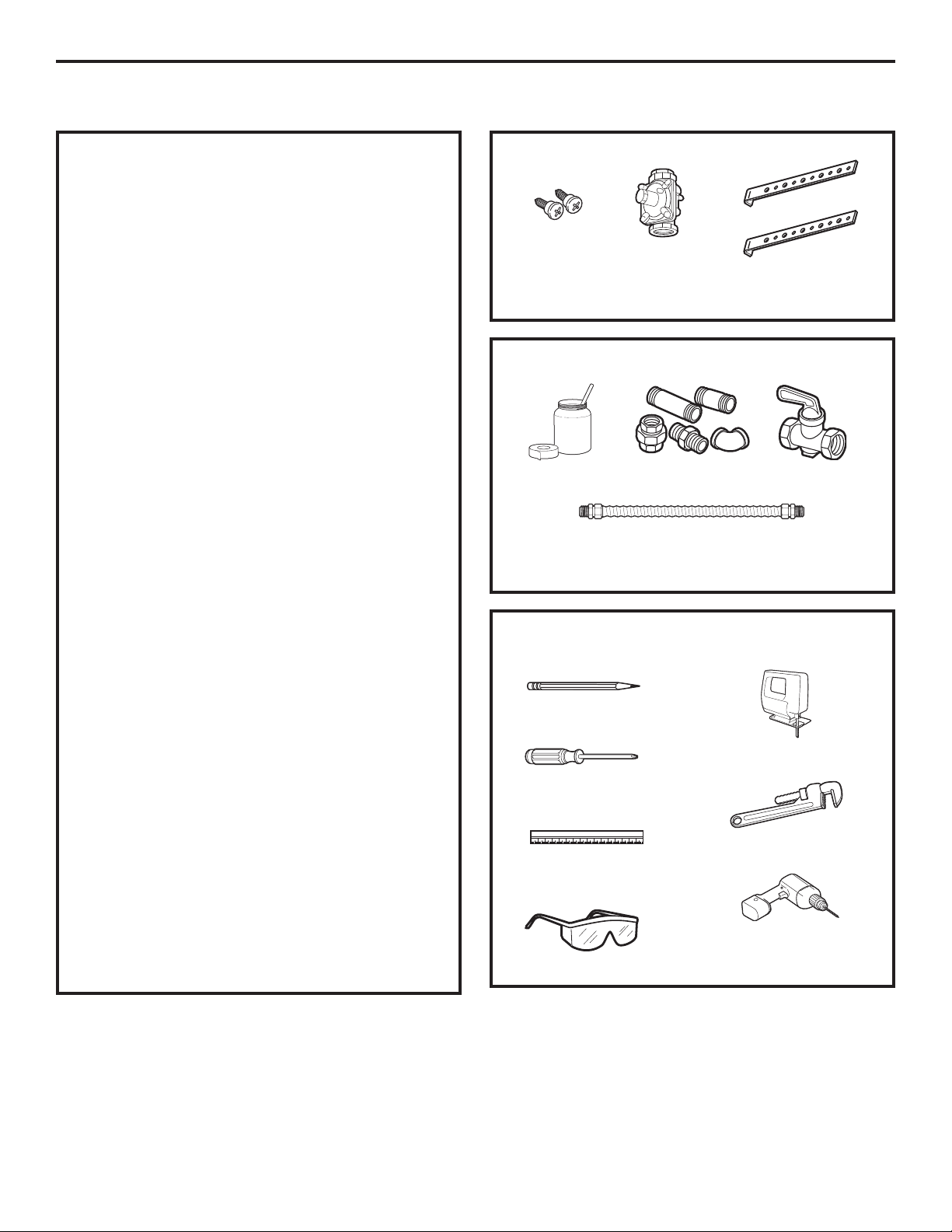
PARTS INCLUDED
2 Screws
Regulator
MATERIALS YOU MAY NEED
Joint Sealant
CSA-Approved Flexible Gas Line
3/8s Min. ID, 1/2s NPT Connection,
3-foot Maximum Length (Massachusetts Only)
Pipe Fittings
2 Hold
Down Brackets
Shut-Off Valve
In Canada your cooktop must be wired and fused
to meet the requirements of the Canadian Electrical
Code.
Be sure the installation of this product in a mobile
home conforms with the Manufactured Home
Construction and Safety Standard, Title 24 CFR,
Part 3280. If this standard does not apply, you
must follow the standard for Manufactured Home
Installations, ANSI/NCSBS A225.1 or with local
codes where applicable.
You can get a copy of the Federal Standard by
Writing:
Office of Mobile Home Standards
HUD Building
451 7th Street, S.W.
Washington, D.C. 24010
TOOLS YOU WILL NEED
FOR INSTALLATION
Pencil
Saber Saw
Phillips-Head
Screwdriver
Pipe Wrench
Ruler or Straightedge
1/8s Drill Bit & Electric or
Hand Drill
Safety Glasses
2
Installation Instructions
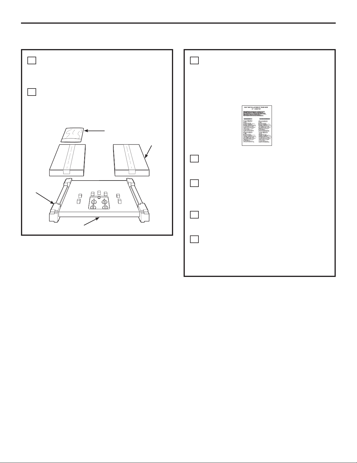
PRE-INSTALLATION CHECKLIST
When preparing cooktop opening, make
A
sure the inside of the cabinet and the
cooktop do not interfere with each other.
(See section on preparing the opening.)
Remove packaging materials, grate boxes,
B
regulator with literature, and literature
package from the cooktop before beginning
installation.
Literature Package
Foam
Packaging
Cooktop
Grate boxes
Remove Installation Instructions from
C
literature pack and read them carefully
before you begin.
Be sure to place all literature (Owners Manual,
Installation Instructions, etc.) in a safe place
for future reference.
Make sure you have all the tools and
D
materials you need before starting the
installation of the cooktop.
Your home must provide the adequate
E
electrical service needed to safely and
properly use your cooktop. (Refer to section
on electrical requirements.)
When installing your cooktop in your home,
F
make sure all local codes and ordinances
are followed exactly as stated.
Make sure the wall coverings, countertop
G
and cabinets around the cooktop can
withstand heat (up to 200°F) generated by
the cooktop.
3
Installation Instructions
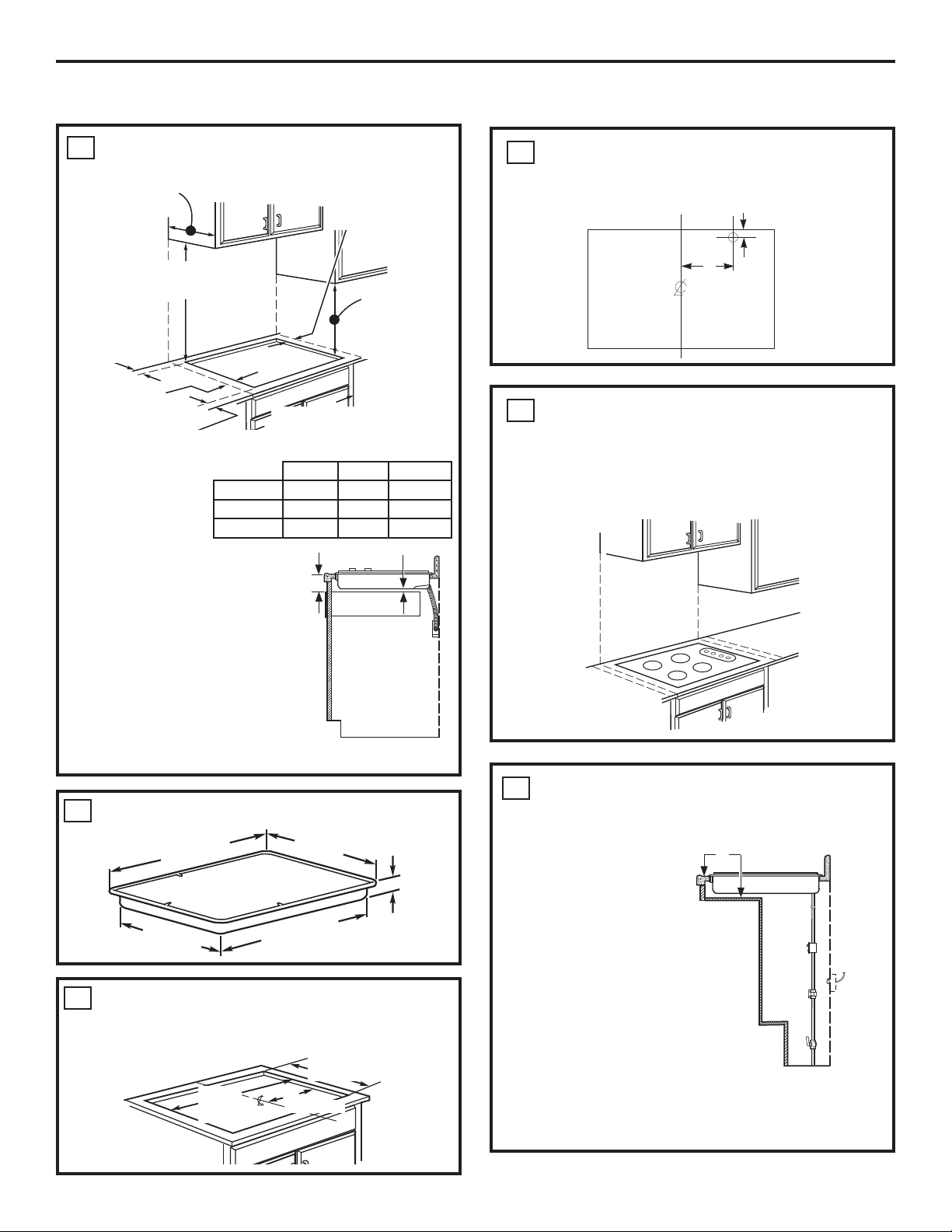
PREPARING THE OPENING
MAINTAIN THE FOLLOWING
1
MINIMUM CLEARANCE DIMENSIONS
13s MAX. Depth
of unprotected
overhead
cabinets
30s MIN. clearance from
countertop to unprotected
overhead surface
C - MIN.
clearance from
cutout to rear
wall
L - MIN. clearance
from cooktop to left
side wall
2-1/2” MIN from cutout to
front of countertop
ALL HORIZONTAL
CLEARANCES MUST
BE MAINTAINED FOR
A MINIMUM OF 18”
ABOVE THE COOKING
SURFACE.
PGP976 3-3/4” 6” 3-3/8”
PGP986 12” 12” 3-3/8”
CGP650 12” 12” 3-3/8”
NOTE: Allow 7/16” minimum
vertical clearance from
3-11/16s
the cooktop bottom (or
3-11/16” minimum depth
from the countertop) to any
combustible surfaces, such as
a cabinet drawer.
30” or wider
cabinet base
R - MIN. clearance
from cutout to right
3 3/4 MIN.
side wall
18s MIN. height
from countertop
to nearest
cabinet on either
side of unit
LR C
7/16s
DRAWER
RECOMMENDED GAS SUPPLY
4
LOCATION FROM BACKWALL
1” Min. From Backwall
Recommended
gas supply
location
MAKE SURE WALL COVERINGS,
5
7s
From Cutout
Center Line
COUNTERTOP AND CABINETS
AROUND COOKTOP CAN WITHSTAND
HEAT (UP TO 200°F) GENERATED BY
COOKTOP
Wall covering,
cabinets and
countertop must
withstand heat
up to 200°F
For island installation, maintain
2-1/2 in. minimum from cutout to
front and back edge of countertop. Maintain 3 in.
minimum from cutout to side edges of countertop.
OVERALL COOKTOP DIMENSIONS
2
36s
Cooktop
18-7/8s
CUTOUT DIMENSIONS OF COUNTERTOP
3
To ensure accuracy, it is best to make a template
21s
3-1/4s
33-11/16s
when cutting the opening in the counter.
19-1/8” width cut
33-7/8”
length
of cut
16-15/16s
FOR AMERICANS WITH DISABILITIES
6
ACT (ADA) FORWARD APPROACH
INSTALLATION ONLY:
5”
Allow 5” minimum
depth between the
countertop and an
enclosure.
NOTE: The enclosure must be made of wood
material. Also, an access panel is required for the
electrical outlet, pressure regulator, shut-off valve,
hold-down brackets, and service.
4
Installation Instructions
INSTALLING THE COOKTOP UNIT
LOCATE ELECTRICAL OUTLET AND
1
GAS SHUT-OFF VALVE BENEATH
CABINET
NEVER REUSE OLD
CONNECTORS WHEN
INSTALLING THIS
UNIT.
Shut Off
Valve
Electrical
Outlet 12s
Below
Countertop
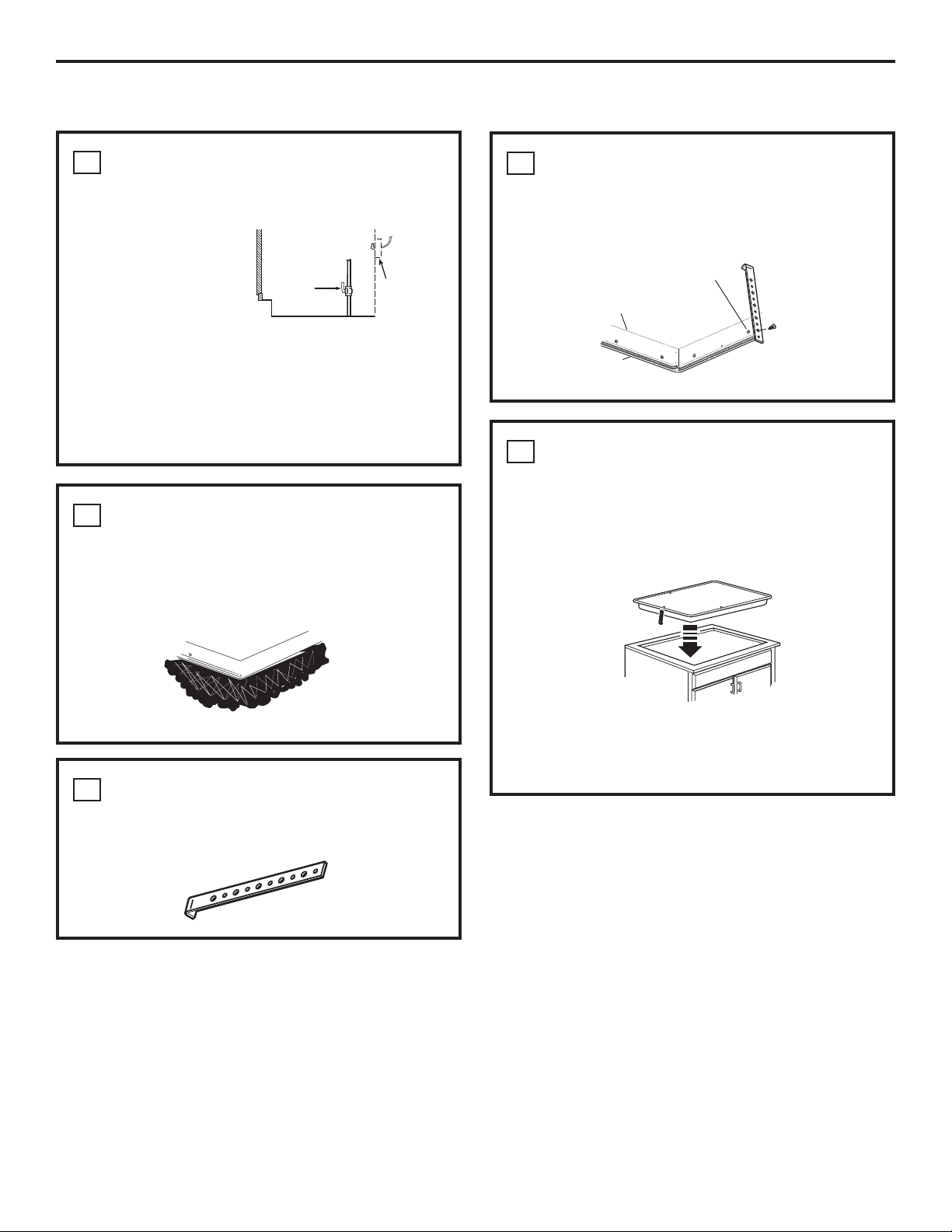
ATTACH BRACKETS TO COOKTOP
4
Remove the screw from the side of the cooktop
and screw the hold-down bracket to the side of the
cooktop unit. Repeat for opposite side of cooktop.
Pre-drilled
Bottom of
Cooktop
hole
Install a manual shut-off valve in the gas line in an
easily accessible location outside the cooktop. Be
sure you know how and where to shut off the gas
supply to the cooktop. Install the electrical outlet
12s below the countertop.
PROTECT SURFACE OF COOKTOP
2
Place a towel or tablecloth onto the countertop.
Lay the cooktop upside down onto the protected
surface.
Bottom of cooktop
Cloth under Cooktop
LOCATE MOUNTING PARTS
3
Remove the hold down brackets from the literature
package.
Cooktop
Surface
INSERT COOKTOP INTO CUTOUT
5
Insert the cooktop centered into the cutout opening.
Make sure the front edge of the countertop is
parallel to the cooktop. Make final check that all
required clearances are met.
Cooktop
Once the unit is in place, screw the
hold- down bracket into the cabinet sides
to secure the unit into place.
5
Installation Instructions
,167$//$7,21³*$6&211(&7,216
PROVIDE ADEQUATE
1
GAS SUPPLY
This cooktop is designed to operate on natural
gas at 5s of water column manifold pressure and
7s of water column (W.C.) supply pressure. It is
shipped from the factory set for natural gas. The
convertible pressure regulator supplied with the
unit must be connected in series with the manifold
of the cooktop and must remain in series with the
supply line regardless of whether natural or L.P.
gas is being used. FOR PROPER OPERATION, THE
MAXIMUM INLET PRESSURE TO THE REGULATOR
MUST BE NO MORE THAN 14s OF WATER COLUMN
PRESSURE. For checking the regulator, the inlet
pressure must be at least 1s W.C.. (or 3.4 KPA)
greater than the regulator output setting. If
the regulator is set for 5s W.C. of water column
pressure, the inlet pressure must be at least 6sW.C.
If the regulator is set for 10sW.C., the inlet pressure
must be at least 11sW.C.. The gas supply line to
the cooktop should be 1/2s or 3/4s pipe.
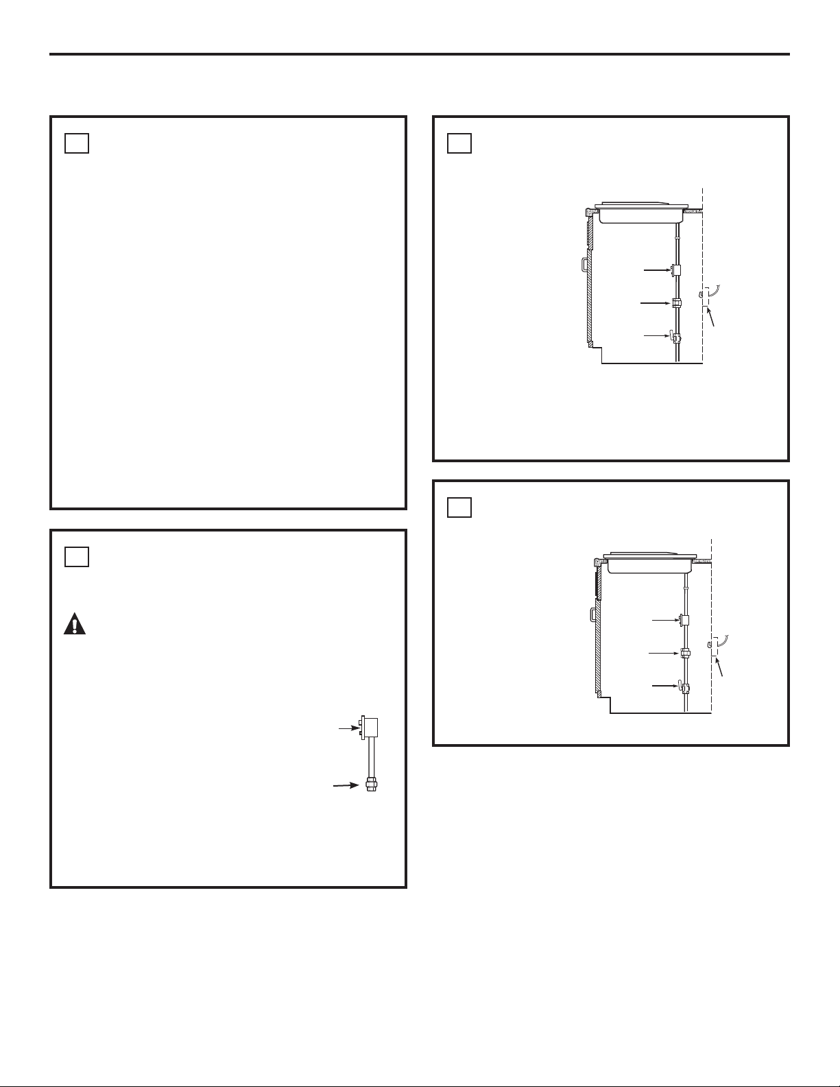
INSTALL REGULATOR ONTO
3
BURNER BOX BOTTOM
Screw the regulator
onto the burner
box bottom pipe
connection. Make
sure the top of
the regulator is
Pressure
Regulator
facing towards the
cabinet front, easily
accessible through
the cabinet doors.
The regulator may
also be installed
Coupling
Shut-Off
Valve
Electrical
Outlet 12s
Below
Countertop
prior to inserting
the cooktop into the cutout if extreme caution is
used to ensure the regulator connection is not
compromised.
COMPLETE CONNECTION WITH A
4
COUPLING
INSTALL REGULATOR
2
NEVER REUSE OLD CONNECTORS WHEN
INSTALLING THIS COOKTOP.
WARNING: Never reuse old flexible
connectors. The use of old flexible connectors
can cause gas leaks and personal injury. Always
use new flexible connectors when installing a gas
appliance.
Pressure
Screw a section of pipe onto
the inlet end of the pressure
regulator and install the
coupling.
To reduce the likelihood of gas leaks, apply teflon
tape or a thread compound approved for use with
LP or Natural gases to all threaded connections.
Regulator
Coupling
Complete the
connection between
the regulator, pipe
coupling, and
the shut-off valve.
Pressure
Regulator
Coupling
Shut-Off
Valve
Electrical
Outlet 12s
Below
Countertop
6
Installation Instructions
CHECK FOR LEAKS
5
LEAK TESTING OF THE APPLIANCE SHALL BE
CONDUCTED ACCORDING TO THE MANUFACTURER’S
INSTRUCTIONS.
Before testing for leaks, make sure all burner knobs
are in the OFF position.
After connecting the cooktop to gas, check system
for leaks with a manometer. If a manometer is not
available, turn the gas supply on to the cooktop
and use a liquid leak detector at all joints and
connections to check for leaks.
Tighten all connections if necessary to prevent gas
leakage in the cooktop or supply line.
DO NOT USE OPEN FLAME TO CHECK FOR
LEAKS!
Disconnect the cooktop and its individual shut-off
valve from the gas supply piping system during any
pressure testing of that system at test pressures
greater than 1/2 psig (3.5 kPa).
Isolate the cooktop from the gas supply piping
system by closing its individual shut-off valve
during any pressure testing of the gas supply
system at test pressures equal to or less than 1/2
psig (3.5 kPa).
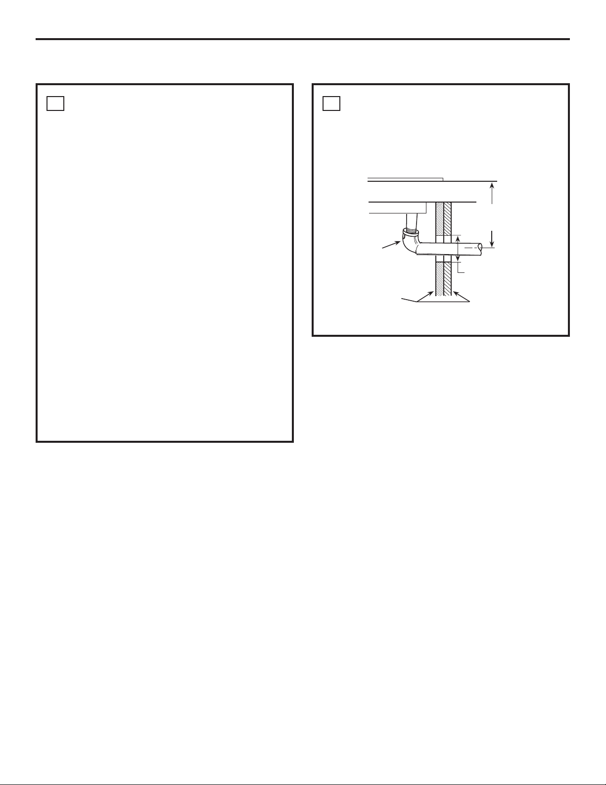
INSTALLATION OVER BUILT-IN
6
OVEN
See built-in oven installation for complete
installation instructions.
5s To Center of
2s Dia. Hole From
Countertop
90° Elbow
2s Dia. Hole
(20 7/8s from front
of Countertop to
Cabinet Sides
View from Front of Cooktop
Hole Center)
7
Installation Instructions
,167$//$7,21³(/(&75,&$/&211(&7,216
WARNING ³Disconnect all electrical
power at the main circuit breaker or fuse box
before installing.
ELECTRICAL SUPPLY AND OUTLET
An adequate electrical supply and outlet must
be used to operate the electrical parts of your
cooktop.
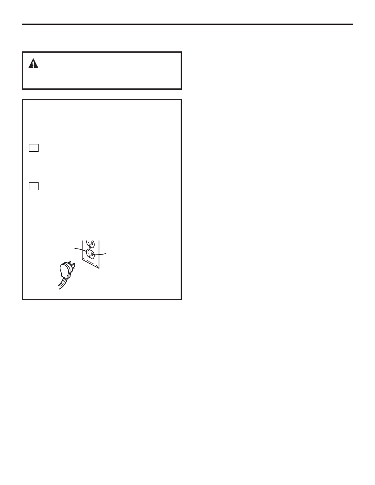
The power cord of this appliance is equipped
A
with a 3-prong (grounding) plug which must
be used with a properly grounded 3-hole
outlet with a standard 120 Volt, 60 cycle AC
household current.
B
If you do not have a 3-hole grounded outlet,
have a qualified electrician change your old
one. DO NOT, UNDER ANY CIRCUMSTANCES,
CUT OR REMOVE THE THIRD (GROUND) PRONG
FROM THE POWER CORD. DO NOT USE AN
ADAPTER. DO NOT USE AN EXTENSION CORD.
N
Insure proper
ground and
L
firm connection
before use
8
Installation Instructions
COOKTOP BURNERS
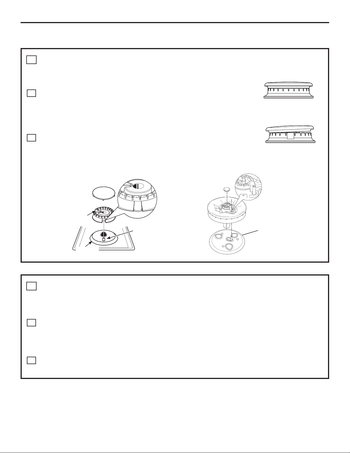
ASSEMBLING THE COOKTOP BURNERS
1
The electrode of the igniter is exposed. Be careful not to turn on any cooktop controls
while the top of the burner is removed. Do not remove the top or touch the electrode
of any burner while another burner is turned on. Electrical shock might result.
Place the burner head onto the burner base. Make sure to place the correct
A
burner head on the correct burner base and that the burner head sits level on
the burner base. The burner heads are not interchangeable. Ensure the slot in
the burner head is positioned over the electrode and that the burner head is
fully inserted inside the burner base. A small gap between the base and head is
normal.
Place the burner caps on the burner heads, making sure to place the correct
B
burner cap on the correct burner head. The burner caps are not
interchangeable. Each cap has three to four pins. Make sure that the burner
caps are properly seated on the burner heads and that none of the pins sit in the stability chamber.
Burner cap properly seated
Burner cap not properly seated
OR
Inner
Burner cap
Burner
head
Electrode
Burner
base
CHECK IGNITERS
2
Burner cap
Burner head
Stability
chamber
Electrode
Burner
base
Operation of the electric igniters should be checked after the cooktop and supply line have been carefully
checked for leaks and the cooktop has been connected to the electrical power.
On models so equipped, check to be sure the cooktop is in the UNLOCKED position.
Push and turn a burner valve to the LITE position. All spark igniters will make a series of sparks (ticking
A
sounds), but only the burner turned to LITE will light.
• The burner should light when gas is available to the burner.
• Once the burner lights, it should be turned out of the LITE position.
Try each valve separately until all burners have been checked.
B
9
Installation Instructions
COOKTOP BURNERS (CONT.)
BURNER IGNITION
3
&RRNWRS6SDUN,JQLWLRQ³:KHQ\RXWXUQ
the cooktop knob to LITE, the spark igniter makes a
series of electric sparks (ticking sounds) which light
the burner. During a power failure, the burners will
not light automatically. In an emergency, a cooktop
burner may be lit with a match by following the
steps below.
On models so equipped, check to be sure the
cooktop is in the UNLOCKED position.
Light a match and hold the flame near the
A
burner you want to light. Wooden matches
work best.
Push in and turn the control knob slowly. Be
B
sure you are turning the correct knob for the
burner you are lighting.
NOTE: If the burner does not light within five seconds,
turn the knob off and wait one minute before trying
again.
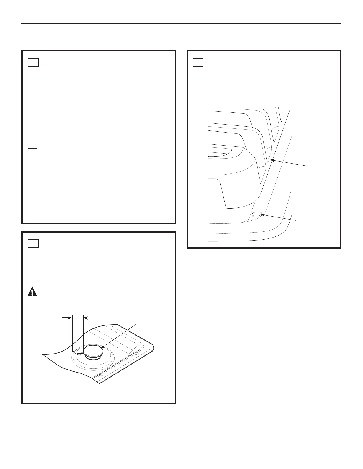
BURNER GRATES
5
The three cooktop grates are designed for specific
positions. For maximum stability, these grates
should only be used in their proper position with
the edges positioned on top of the black bumpers
as shown
Grate
Black Grate
Bumpers
THE BURNER FLAMES
4
Turn each burner on. Flames should be blue in color
with no trace of yellow. The burner flames should
not flutter or blow away from the burner. The flame
should be no less than 1/4s on the lowest setting
and no greater than 1-1/2s on highest setting.
CAUTION: If you attempt to measure the
flame, please use caution. Burns could result.
1/4s to
1-1/2s
Burners should be checked frequently
Cooktop Burner
10
Installation Instructions
OPERATION CHECKLIST
Make sure all controls are left in the OFF
A
position. Check to be sure the cooktop is in the
UNLOCKED position (on models so equipped).
Make sure the flow of air to and from the
B
cooktop is unobstructed.
The serial plate for your cooktop is located on
C
the bottom of the burner box. In addition to the
model and serial numbers, it tells you the ratings
of the burners and the type of fuel and pressure
the cooktop was adjusted for when it left the
factory.
When ordering parts, always include the serial
D
number, model number and a code letter to
ensure proper replacement parts.
Recheck Steps:
E
Double check to make sure everything in this
guide has been completed. Rechecking steps
will ensure safe use of the cooktop.
11
Installation Instructions
MAKING THE LP CONVERSION
SAFETY INFORMATION YOU
1
SHOULD KNOW
The pressure regulator and burner orifices are set
for natural gas. To use LP gas, the regulator and
burner orifices must be converted. The LP orifice
spuds for the cooktop burners are attached to
the regulator along with separate LP conversion
instructions.
CAUTION: The cooktop, as shipped from
the factory, is set for use with natural gas. If you
wish to use your cooktop with LP gas, you must
first replace the orifices and convert the pressure
regulator.
WARNING: This conversion must be
performed by a qualified installer or gas supplier in
accordance with the manufacturer’s instructions
and all codes and requirements of the authority
having jurisdiction. Failure to follow instructions
could result in serious injury or property damage.
The qualified agency performing this work assumes
responsibility for the conversion.
CAUTION: The following adjustments
must be made before turning on the burner. Failure
to do so could result in serious injury. Be sure
pressure regulator has been converted as
described in Step 2.
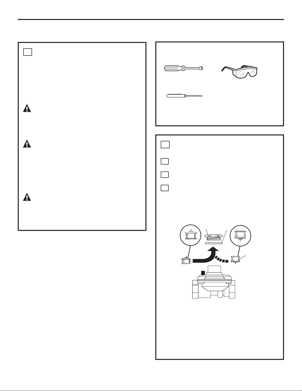
TOOLS YOU WILL NEED
FOR LP CONVERSION
7mm Nutdriver
Safety Glasses
Small Flat-Head
Screwdriver (4mm or
5/32s tip size, 60mm
or 2-3/8” long)
ADJUST YOUR COOKTOP FOR USE
2
WITH LP GAS
Disconnect all electrical power, at the main
A
circuit breaker or fuse box.
Shut off the gas supply to the cooktop
B
by closing the manual shut-off valve.
Adjust the pressure regulator, by the following
C
instructions:
• Unscrew the cap.
• Carefully look at the spring retainer to locate
the NAT or LP position.
Cap
LP
Gasket
NAT
NAT
LP
NAT
NAT.
Position
Pressure Regulator
LP
NAT
LP
L.P./Propane
Position
Spring
Retainer
• Turn the spring retainer over by rotating it
90 deg., pull it from the cap, turn the spring
retainer over so that LP is showing, insert it
back into the cap, and then rotate it 90 deg.
into position.
• Screw the cap back onto the regulator and
tighten.
12
Installation Instructions
MAKING THE LP CONVERSION (CONT.)
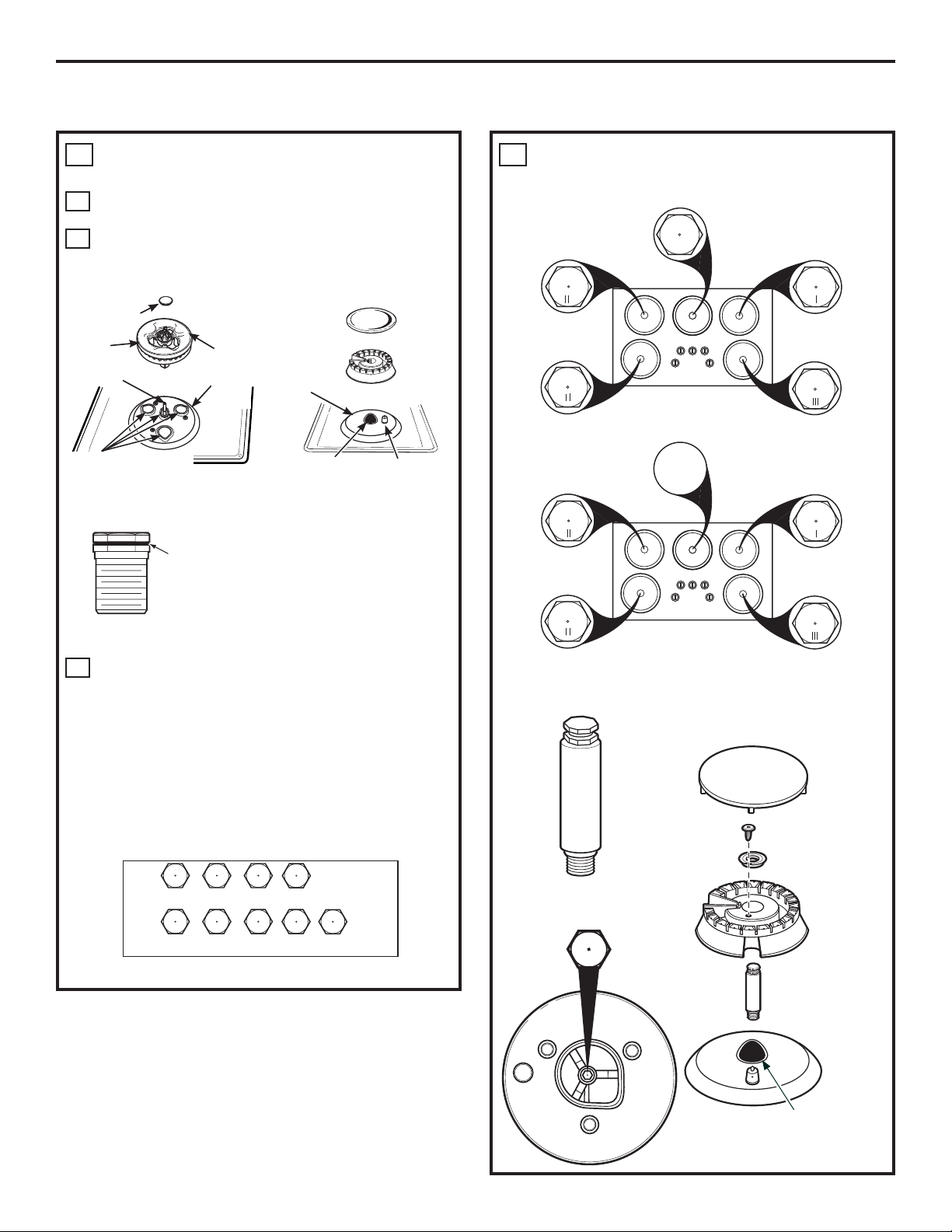
CHANGE COOKTOP BURNER
3
ORIFICES
Remove the grates, burner caps, and burner
A
heads.
Using a 7mm nut driver, remove the burner
B
orifices. These may be accessed through the
burner holes in the cooktop.
Inner
burner cap
Burner
base
Electrode
Orifice spuds located
through these openings
Tri-Ring Burner
Retainer
Ring
Outer
burner
cap
Burner
base
OR
Burner
base
Orifice spud located
through this opening
NOTE: On all burners, the
orifices have a spring-loaded
retaining ring around the hex
head to hold the orifice in the
nut driver during installation
and removal. A slight amount
of force is required to push the
nut driver down over the ring.
Burner
cap
Burner
head
Electrode
CHANGE COOKTOP BURNER
3
ORIFICES (CONT.)
PGP976
86 L
86 L
CGP650 &
PGP986
86 L
86 L
107 L
IV
See
Right
Main: 58 L (x3)
Simmer: 51 L
64 L
91 L
64 L
91 L
Locate the LP orifices attached to the regulator
C
along with separate LP conversion instructions.
They will have a digit for size and a letter for type
of gas, on the top or side.
(Important: Save the
orifices removed from the appliance for future
use.)
Each orifice will show a series of engraved
marks, (I, II, III, IV or V), located on the top.
These marks denote the location of each orifice to the
cooktop burner.
I II III
For PGP976 Models
I II III
For PGP986 & CGP650 Models
x2x1
x1
x2 x3
IV
x1x1x1
51L
V
(Shorter)
V
x1
CENTER BURNER
17,000 BTU/hr Extra Large Burner (PGP976 Models)
Burner
Cap
Set Screw
Choke
Extended spud for center
extra large burner
107 L
IV
Extended
Spud
Orifice spud located
through this opening
Burner
Head
Base
13
Installation Instructions
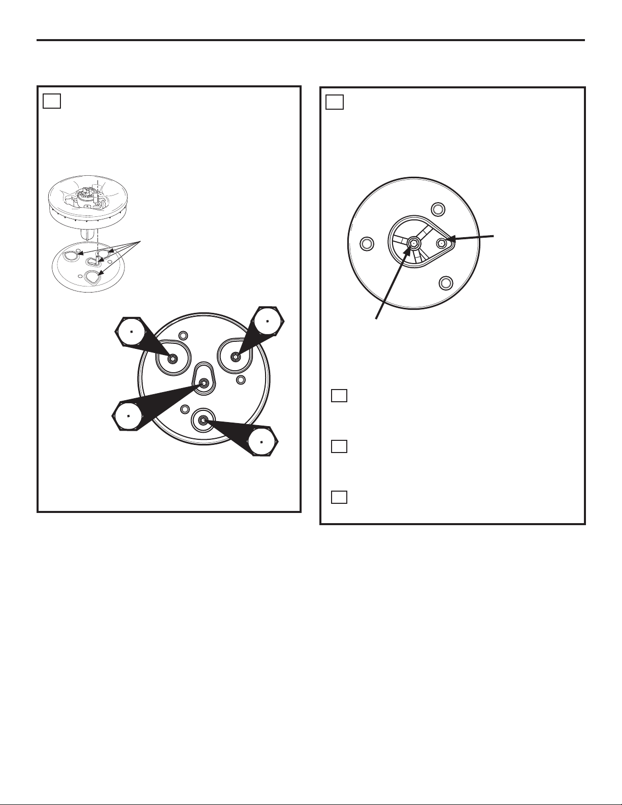
CHANGE COOKTOP BURNER
3
ORIFICES (CONT.)
CENTER BURNER
20,000 BTU/hr Tri-Ring Burner (PGP986 and CGP650
Models)
Orifice spuds located
through these
openings.
Main Orifice
58L
V
51L
V
Simmer Orifice
(Shorter)
Main Orifice
58L
V
58L
V
Main Orifice
CHANGE COOKTOP BURNER
3
ORIFICES (CONT.)
LEFT FRONT BURNER
(PGP986 and CGP650 Models)
Griddle Screw
The griddle screw
is marked with N
for natural gas
and L for liquefied
petroleum.
Main Orifice
NOTE: The main orifice is located in the center of
the burner, while the griddle screw is located to the
right of the center of the burner.
Install the LP Propane orifices and griddle
D
screw (on PGP986 and CGP650 models only)
in their precise locations as noted in the
earlier illustrations.
Return the natural gas orifices and griddle
E
screw to the bracket and attach the bracket
and the instruction sheet to the pressure
regulator using the screw removed previously.
Replace the burner heads, caps and grates.
F
14
Installation Instructions
MAKING THE LP CONVERSION (CONT.)
ADJUST BURNER FLAMES
4
Turn all burners full on and check the flames.
A
They should be blue in color with some yellow
tipping at the ends of the flame. Foreign
particles in the gas line may cause an orange
flame at first, but this will soon disappear.
Turn the cooktop burner knob to the lowest
B
setting while observing the flame.
Adjust the low flame setting using the valve bypass
screw as follows:
Low-setting adjustments must be made with two
other burners in operation on a medium setting.
This prevents the low flame from being set too low,
resulting in the flame being extinguished when
other burners are turned on.
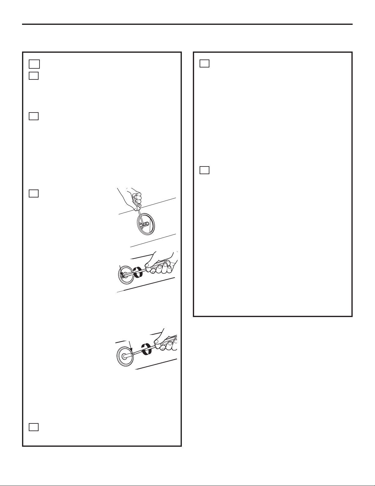
To adjust the flame,
C
remove the knobs. Use
screwdriver to remove
valve stem plugs as
shown.
Insert a screwdriver
through the access hole
in valve switch. Engage
adjustment screw in
valve. Refer to the
illustration below that
matches the adjustment
screw location for
your model. The
griddle burner (PGP986
and CGP650) has 2
adjustment screws,
one for the left rear
burner and one for the
left front burner during
griddle control. Griddle
control must be turned
to LO when making this
adjustment.
• If the flames were too
small or fluttered, open
the valve more than the original setting.
Left of stem
For left front griddle
burner and tri-ring
burner simmer
adjustment screw
Inside stem
For all burners
except tri-ring
E
Test 1 – Temporarily replace knobs. Turn the
Test 2 – With the burner on the lowest setting,
F
After the adjustment is made, turn all burners off.
Ignite each burner individually. Observe the flame
at the “HI” position. Rotate the valve to the lowest
setting and be sure that the flame size decreases
as the valve is rotated counterclockwise.
TO CONVERT THE COOKTOP BACK TO NATURAL
GAS, REVERSE THE STEPS UNDER MAKING THE LP
CONVERSION.
Once the conversion is complete and checked ok,
replace valve stem plugs and knobs, and fill out
the LP sticker. Include your name, organization and
date conversion was made. Apply the sticker near
the cooktop gas inlet opening to alert others in
the future that this appliance has been converted
to LP gas. If converting back to natural gas from
LP, please remove the sticker so others know the
appliance is set to use natural gas.
Testing Flame Stability:
knob from “HI” to the lowest setting
quickly. If the flame goes out at the
lowest setting, increase the flame size
and test again.
open and close the cabinet door
under the cooktop. If the flame is
extinguished by the air currents
created by the door movement,
increase the flame height and test
again.
Flame Recheck:
• If the flames blew away from the burner,
close the valve more than the original
setting.
Make the adjustment by slowly turning the
D
screw until flame appearance is correct.
15
 Loading...