

GE JGP970BEK3BB, JGP970BEK6BB, JGP970SEK5SS, JGP970SEK6SS, JGP970TEK3WW Installation Guide
...
Installation
36s Sealed Gas Cooktop
JGP633, JGP970, PGP966, ZGU36
Instructions
Questions? Call 800.GE.CARES (800.432.2737) or Visit our Website at: GEAppliances.com
In Canada, call 1.800.561.3344 or Visit our Website at: www.geappliances.ca
IN THE COMMONWEALTH OF
MASSACHUSETTS:
• This product must be installed by a licensed
plumber or gas fitter.
• When using ball-type gas shut-off valves, they
shall be the T-handle type.
• A flexible gas connector, when used, must not
exceed 3 feet.
BEFORE YOU BEGIN
Read these instructions completely and carefully.
•
IMPORTANT ³ Save these instructions
for local inspector’s use.
•
IMPORTANT ³Observe all governing
codes and ordinances.
•
Note to Installer – Be sure to leave these
instructions with the Consumer.
• Note to Consumer – Keep these instructions for
future reference.
• Product failure due to improper installation is not
covered under the Warranty.
WARNING
properly grounded.
•
IMPORTANT ³ Leak testing of the
appliance shall be conducted according to the
manufacturer’s instructions.
• Proper installation is the responsibility of the
installer and product failure due to improper
installation is NOT covered under warranty.
WARNING
at the main circuit breaker or fuse box before
installing.
This appliance must be
Disconnect all electrical power
FOR YOUR SAFETY:
WARNING
instructions is not followed exactly, a fire, explosion
or gas leak may result causing property damage,
personal injury or death.
Do not store or use gasoline or other flammable vapors
and liquids in the vicinity of this or any other appliance!
Do not install this product with an air curtain hood
or other range hood that operates by blowing air
down on the cooktop. This airflow may interfere
with operation of the gas burners resulting in fire or
explosion hazard.
If the information in these
WHAT TO DO IF YOU SMELL
GAS:
• Do not try to light any appliance. Do not touch any
electrical switch; do not use any phone in your
building.
• Immediately call your gas supplier from a
neighbor’s phone. Follow the gas supplier’s
instructions.
• If you cannot reach your gas supplier, call the fire
department.
Installation and service must be performed by a
qualified installer, service agency or the gas supplier.
This cooktop has been design certified by CSA
International. You’ll find safety precautions in your
Owner’s Manual.
Read them carefully.
• Installation of this cooktop must conform with local
codes or, in the absence of local codes with the
National Fuel Gas Code,
• Be sure your cooktop is installed properly by a
qualified installer or service technician.
• To eliminate reaching over surface burners,
cabinet storage above burner should be avoided.
• Do not install the unit near an outside door or
where a draft may affect its use.
31-10861-2 (05-17 GEA)
1

Installation Instructions
IMPORTANT SAFETY INSTRUCTIONS
ELECTRICAL REQUIREMENTS
This appliance must be supplied with the proper
voltage and frequency and connected to an
individual, properly grounded branch circuit,
protected by a circuit breaker or fuse having
amperage as noted on the rating plate.
We recommend you have the electrical wiring and
hookup of your cooktop connected by a qualified
electrician. After installation, have the electrician
show you where your main cooktop disconnect is
located.
Check with your local utilities for electrical codes
which apply in your area. Failure to wire your
cooktop according to governing codes could result
in a hazardous condition.
If there are no codes, your cooktop must be wired
and fused to meet the requirements of the National
(OHFWULFDO&RGH$16,1)3$1R³/DWHVWHGLWLRQ
You can get a copy by writing:
National Fire Protection Association
Batterymarch Park
Quincy, MA 02269
PARTS INCLUDED
2 Screws
Foam Tape
(Glass Top
Models Only)
MATERIALS YOU MAY NEED
Joint Sealant
CSA-Approved Flexible Gas Line
3/8s Min. ID, 1/2s NPT Connection,
3-foot Maximum Length (Massachusetts Only)
Pipe Fittings
2 Hold
Down Brackets
Shut-Off Valve
In Canada your cooktop must be wired and fused
to meet the requirements of the Canadian Electrical
Code, CSA C22.1-02.
Be sure the installation of this product in a mobile
home conforms with the Manufactured Home
Construction and Safety Standard, Title 24 CFR,
Part 3280.
If this standard does not apply, you must follow
the standard for Manufactured Home Installations,
ANSI A225.1 and Manufactured Home Installations,
Sites and Communities and ANSI/NFPA 501A or
with local codes.
You can get a copy of the Federal Standard by
Writing:
Office of Mobile Home Standards
HUD Building
451 7th Street, S.W.
Washington, D.C. 24010
TOOLS YOU WILL NEED
FOR INSTALLATION
Pencil
Saber Saw
Phillips-Head
Screwdriver
Pipe Wrench
Ruler or Straightedge
1/8s Drill Bit & Electric or
Hand Drill
Safety Glasses
2
Installation Instructions
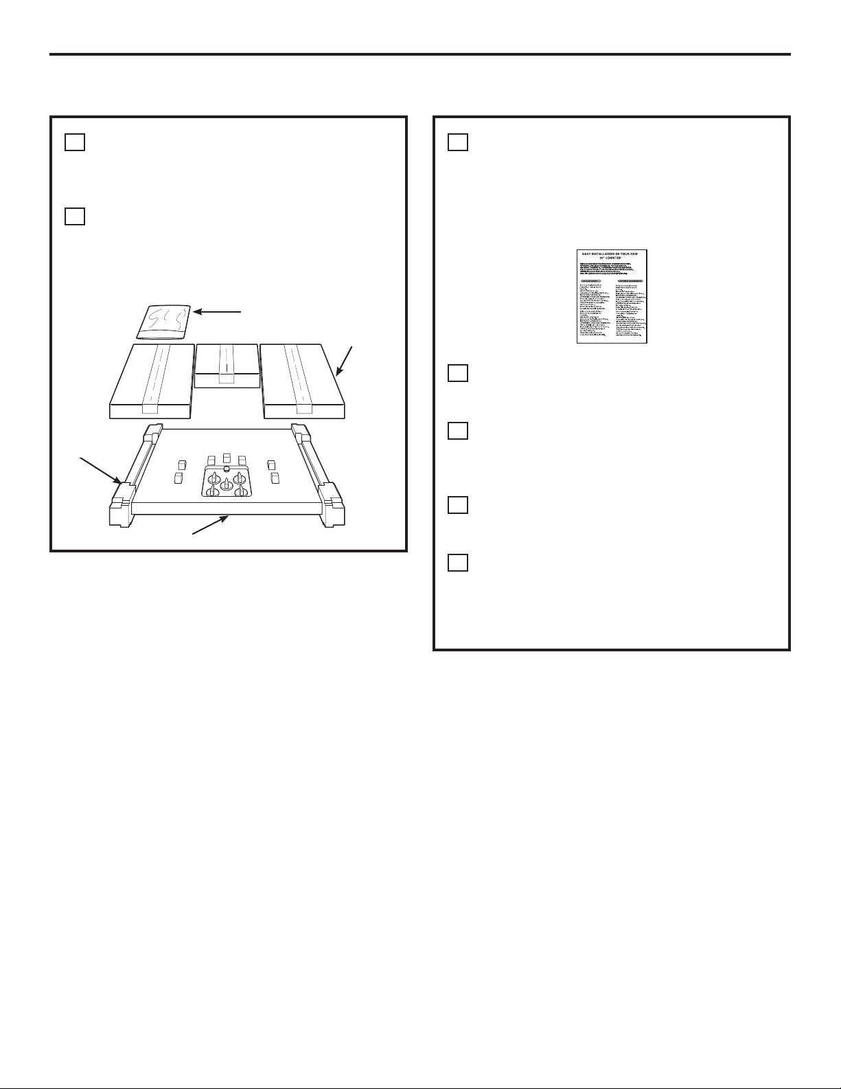
PRE-INSTALLATION CHECKLIST
When preparing cooktop opening, make
A
sure the inside of the cabinet and the
cooktop do not interfere with each other.
(See section on preparing the opening.)
Remove packaging materials, grate boxes,
B
regulator with literature, and literature
package from the cooktop before beginning
installation.
Literature Package
Foam
Packaging
Cooktop
Grate boxes
Remove Installation Instructions from
C
literature pack and read them carefully
before you begin.
Be sure to place all literature, Use and Care,
Installations, etc. in a safe place
for future reference.
Make sure you have all the tools and
D
materials you need before starting the
installation of the cooktop.
Your home must provide the adequate
E
electrical service needed to safely and
properly use your cooktop. (Refer to section
on electrical requirements.)
When installing your cooktop in your home,
F
make sure all local codes and ordinances
are followed exactly as stated.
Make sure the wall coverings, countertop
G
and cabinets around the cooktop can
withstand heat (up to 200°F) generated by
the cooktop.
3
Installation Instructions
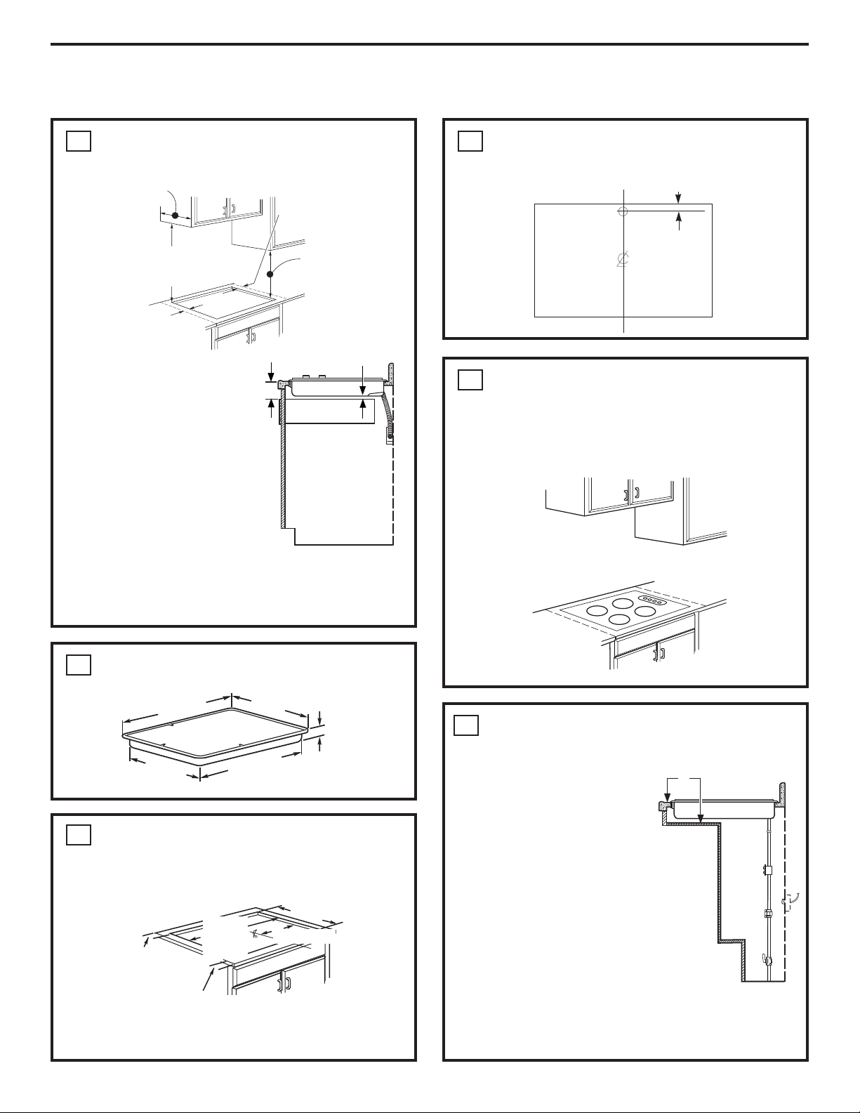
PREPARING THE OPENING
MAINTAIN THE FOLLOWING
1
MINIMUM CLEARANCE DIMENSIONS
13s MAX. Depth of unprotected
overhead cabinets
30s MIN. clearance from countertop
to unprotected overhead surface
3-3/4s MIN. clearance from
cutout to side wall on the
left of the unit
6s MIN. clearance from
3 3/4 MIN.
cutout to side wall on the
right of the unit
18s MIN. height
from countertop to
nearest cabinet on
either side of unit
7/16s
RECOMMENDED GAS SUPPLY
4
LOCATION FROM BACKWALL
1” Min. From Backwall
Recommended
gas supply
location
From Cutout
Center Line
NOTE: Allow 7/16”
minimum vertical
clearance from the
3-5/8s
DRAWER
cooktop bottom (or
3-5/8” minimum depth
from the countertop)
to any combustible
surfaces, such as a
cabinet drawer.
For island installation,
maintain 2-1/2 in.
minimum from cutout to front and back edge of
countertop. Maintain 3 in. minimum from cutout to
side edges of countertop.
OVERALL COOKTOP DIMENSIONS
2
21s(21-1/4s Max. for
36s
Cooktop
18-7/8s
Glass Top models)
33-11/16s
3-3/16s
(3-1/16” on
Model ZGU36)
MAKE SURE WALL COVERINGS,
5
COUNTERTOP AND CABINETS
AROUND COOKTOP CAN
WITHSTAND HEAT (UP TO 200°F)
GENERATED BY COOKTOP
Wall covering,
cabinets and
countertop must
withstand heat
up to 200°F
FOR AMERICANS WITH DISABILITIES
6
ACT (ADA) FORWARD APPROACH
INSTALLATION ONLY:
5”
CUTOUT DIMENSIONS OF
3
COUNTERTOP
To ensure accuracy, it is best to make a template
when cutting the opening in the counter.
19-1/8” width cut
2-1/4” Min. Between
cutout and the wall
behind the cooktop
2-1/2” Min. from
front edge of cutout
and front edge of
33-7/8”
length
of cut
countertop
16-15/16s
Allow 5” minimum
depth between the
countertop and an
enclosure.
NOTE: The enclosure must be made of wood
material. Also, an access panel is required for the
electrical outlet , pressure regulator, shut-off valve,
hold-down brackets, and service.
4
Installation Instructions
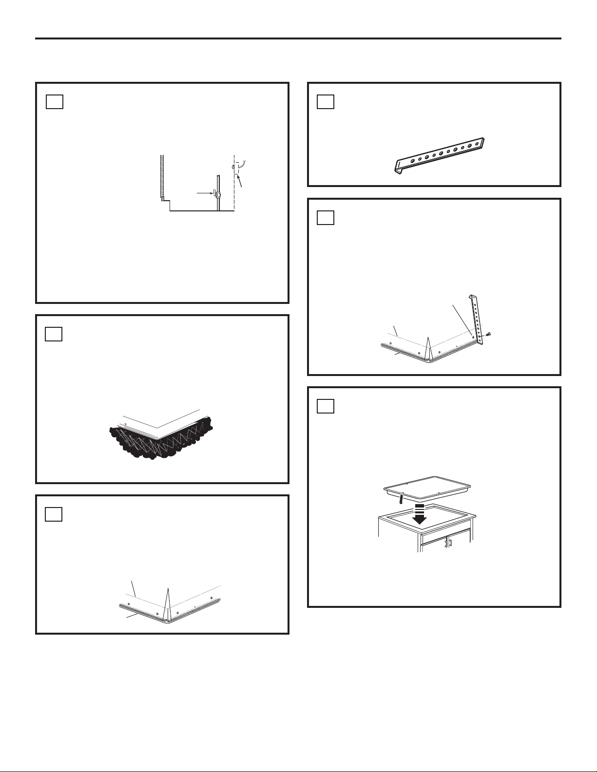
INSTALLING THE COOKTOP UNIT
LOCATE ELECTRICAL OUTLET AND
1
GAS SHUT-OFF VALVE BENEATH
CABINET
NEVER REUSE OLD
CONNECTORS WHEN
INSTALLING THIS
UNIT.
Install a manual shut-off valve in the gas line in an
easily accessible location outside the cooktop. Be
sure you know how and where to shut off the gas
supply to the cooktop. Install the electrical outlet
12s below the countertop.
PROTECT SURFACE OF COOKTOP
2
Place a towel or tablecloth onto the countertop.
Lay the cooktop upside down onto the protected
surface.
Shut-Off
Valve
Electrical
Outlet 12s
Below
Countertop
LOCATE MOUNTING PARTS
4
Remove the hold-down brackets from the literature
package.
ATTACH BRACKETS TO COOKTOP
5
Remove the screw from the bottom of the cooktop
and screw the hold-down bracket
to the side of the cooktop unit. Repeat for opposite
side of cooktop.
Pre-drilled
Bottom
of Cooktop
Cooktop
Glass
hole
Foam Tapes
Bottom of cooktop
Cloth under Cooktop
ATTACH FOAM TAPE
3
(glass maintop models only)
Apply the foam tape around the outer edge
of the glass. Do not overlap the foam tapes.
Bottom of Cooktop
Cooktop Glass
Foam Tapes
INSERT COOKTOP INTO CUTOUT
6
Insert the cooktop centered into the cutout opening.
Make sure the front edge of the countertop is
parallel to the cooktop. Make final check that all
required clearances are met.
Cooktop
Once the unit is in place, screw the hold-down
bracket into the cabinet sides to secure the unit
into place.
5
 Loading...