

Page 1
I stallatio
30" SealedGasCooktop
I structio s
Questions?Call 800.GE.CARES(800.432.2737 or Visitour Website at:ge.com
In Canada, call 1.800.561.3344 or Visitour Website at: www.geappliances.ca
JGP329 JGP333, JGP940, PGP943
IN THE COMMONWEALTH OF
MASSACH USETTS:
, This product must be installed by a licensed
plumber or gas fitter.
, When using ball-type gas shut-off valves, they
shall be the T-handle type.
, A flexible gas connector, when used, must not
exceed 3 feet.
BEFORE YOU BEGIN
Read these instructions completely
and carefully.
.IMPORTANT - Savetheseinstructions
for local inspector's use.
, IMPORTANT - Observeallgoverning
codes and ordinances.
, Note to Installer- Be sure to leave these
instructions with the Consumer.
, Note to Consumer - Keep these instructions for
future reference.
i
FOR YOUR SAFETY:
,_WARNING - iftheinformation
in this manual is not followed exactly, o fire,
explosion or gas leak may result causing property
damage, personal injury or death.
Do not store or use gasoline or other flammable
vapors and liquids in the vicinity of this or any other
appliance!
WHAT TO DO IF YOU SMELL
GAS:
Do not try to light any appliance. Do not touch
any electrical switch; do not use any phone in
your building.
Immediately call your gas supplier from a
neighbor's phone. Follow the gas supplier's
instructions.
, If you cannot reach your gas supplier, call the fire
department.
Installation and service must be performed
by a qualified installer, service agency or
the gas supplier.
, Product failure due to improper installation is not
covered under the Warranty.
AWARNING - Thisappliancemust be
properlygrounded.
. IMPORTANT - Leak testingofthe
applianceshallbe conducted accordingto the
manufacturer's instructions.
, Proper installation is the responsibility of the
installer and product failure due to improper
installation is NOT covered under warranty.
WARN ING - Disconnectallelectrical
power at the main circuit breaker
or fuse box before installing.
31-i0835 (II-IIGE) i
This cooktop has been design certified
by CSA International. You'll find safety precautions
in your Owner's Manual.
Read them carefully.
Installation of this cooktop must conform with
local codes or in the absence of local codes with
the National Fuel Gas Code, ANSI Z223.1/NFPA
54-Latest edition.
Be sure your cooktop is installed properly by a
qualified installer or service technician.
To eliminate reaching over surface burners,
cabinet storage above burner should be avoided.
Do not install the unit near an outside door or
where a draft may affect its use.
Page 2
Installation Instructions
IMPORTANT SAFETY INSTRUCTIONS
ELECTRICAL REQUIREMENTS
This appliance must be supplied with the proper
voltage and frequency and connected to an
individual, properly grounded branch circuit,
protected by a circuit breaker or fuse having
amperage as noted on the rating plate.
We recommend you have the electrical wiring and
hookup of your cooktop connected by a qualified
electrician. After installation, have the electrician
show you where your main cooktop disconnect is
located.
Check with your local utilities for electrical codes
which apply in your area. Failure to wire your
cooktop according to governing codes could result
in a hazardous condition.
If there are no codes, your cooktop must be wired
and fused to meet the requirements
of the National Electrical Code, ANSI/NFPA No. 70--
Latest edition. You can get a copy
by writing:
National Fire Protection Association
Batterymarch Park
Quincy, P1A 02269
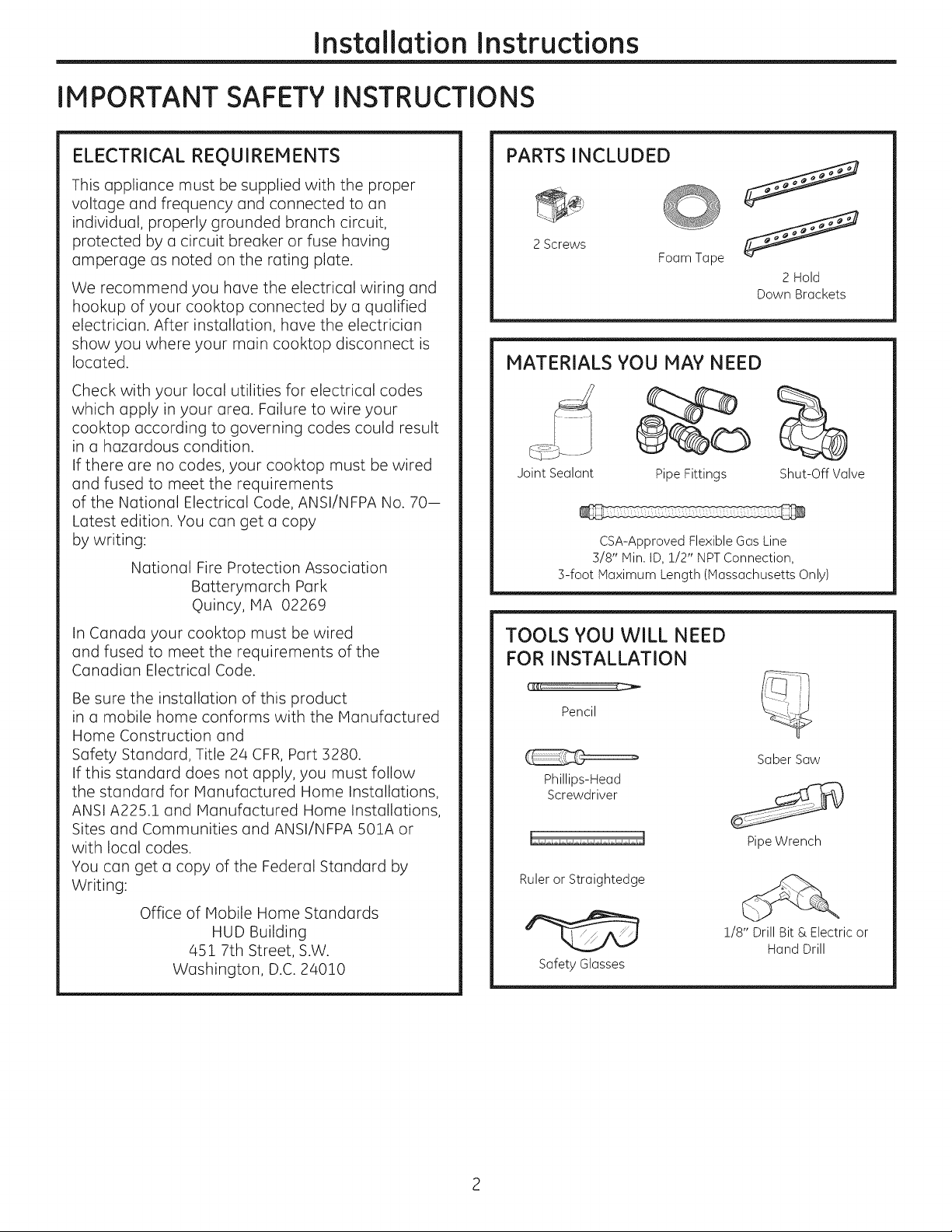
PARTS INCLUDED
2Screws
Foam Tape
MATERIALS YOU MAY NEED
Joint Sealant Pipe Fittings
CSA-Approved Flexible Gas Line
3/8" Min. ID, 1/2" NPTConnection,
3-foot Maximum Length (Massachusetts Only)
2 Hold
Down Brackets
Shut-Off Valve
In Canada your cooktop must be wired
and fused to meet the requirements of the
Canadian Electrical Code.
Be sure the installation of this product
in a mobile home conforms with the Manufactured
Home Construction and
Safety Standard, Title 24 CFR, Part 3280.
If this standard does not apply, you must follow
the standard for Manufactured Home Installations,
ANSI A225.1 and Manufactured Home Installations,
Sites and Communities and ANSI/NFPA 501A or
with local codes.
You can get a copy of the Federal Standard by
Writing:
Office of Mobile Home Standards
HUD Building
451 7th Street, S.W.
Washington, D.C. 24010
TOOLS YOU WILL NEED
FOR INSTALLATION
Pencil
Saber Saw
Phillips-Head
Screwdriver
Pipe Wrench
Ruler or Straightedge
!/8" Drill Bit & Electric or
Hand Drill
Safety Glasses
Page 3
Installation Instructions
PRE-INSTALLATION CHECKLIST
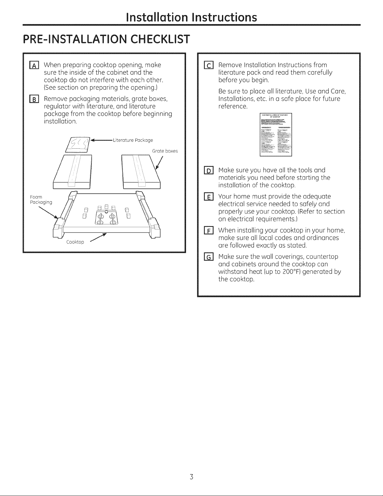
When preparing cooktop opening, make
[Z]
sure the inside of the cabinet and the
cooktop do not interfere with each other.
(See section on preparing the opening.)
Remove packaging materials, grote boxes,
@
regulator with literature, and literature
package from the cooktop before beginning
installation.
Foam_ _
Pac / _ _ _ _
Cooktop J
Package
Grate boxes
Remove Installation Instructions from
E1
literature pack and read them carefully
before you begin.
Be sure to place all literature, Use and Care,
Installations, etc. in a safe place for future
reference.
Hake sure you have all the tools and
El
materials you need before starting the
installation of the cooktop.
Your home must provide the adequate
El
electrical service needed to safely and
properly use your cooktop. (Refer to section
on electrical requirements.)
When installing your cooktop in your home,
El
make sure all local codes and ordinances
are followed exactly as stated.
Hake sure the wall coverings, countertop
[]
and cabinets around the cooktop can
withstand heat (up to 200°F) generated by
the cooktop.
Page 4
Instollotion Instructions
PREPARING THE OPENING
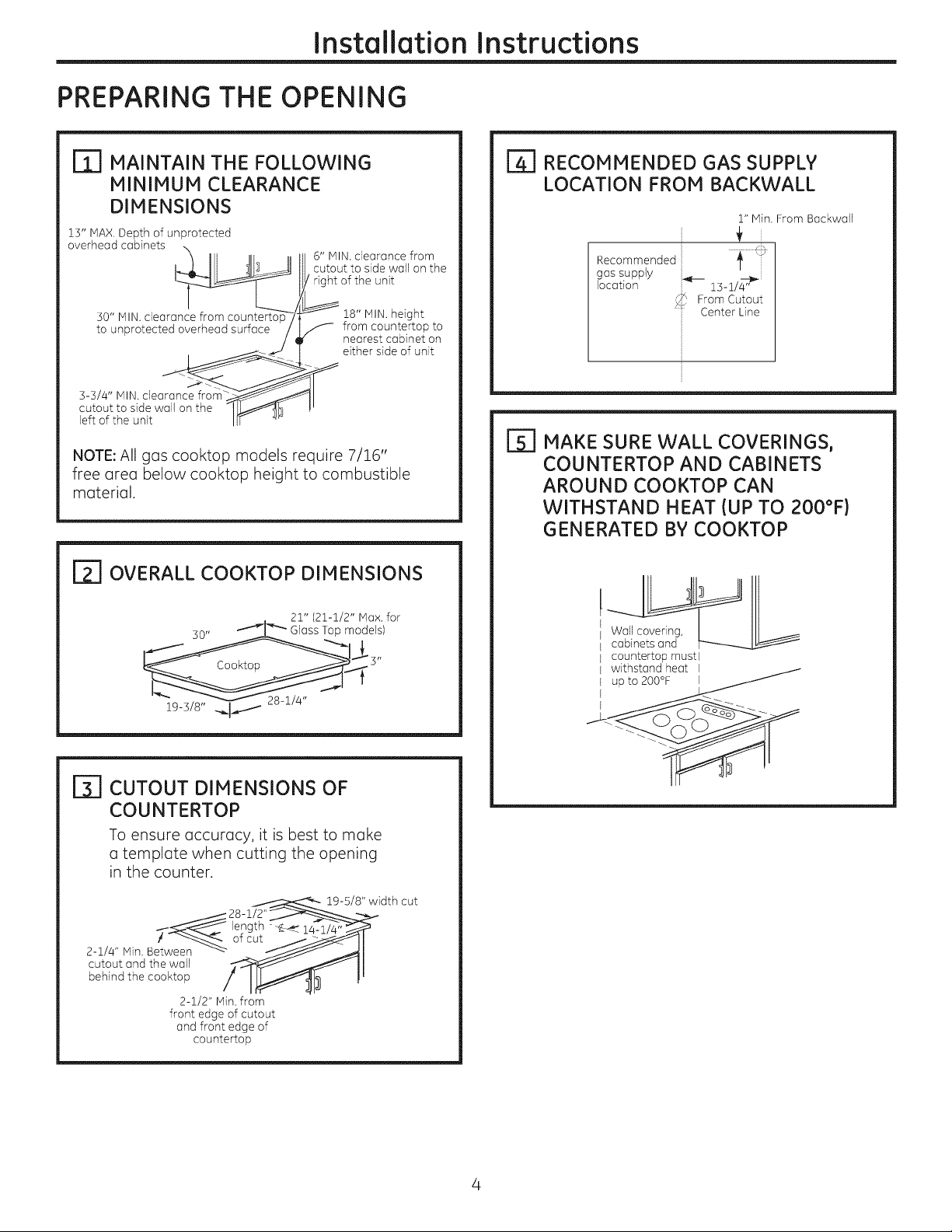
MAINTAIN THE FOLLOWING
MINIMUM CLEARANCE
DIMENSIONS
13" IVlAX.Depth of unprotected
6" MIN. clearance from
II cutout to side wall on the
overhead cabinets _
3-3/4" MIN.clearance from_
right of the unit
_18" HIN. height
f from countertop to
nearest cabinet on
either side of unit
NOTE: All gas cooktop models require 7/16"
free area below cooktop height to combustible
material.
ITI OVERALL COOKTOP DIMENSIONS
| RECOMMENDED GAS SUPPLY
LOCATION FROM BACKWALL
1" Min. From Backwall
Rec°mmended ii _ _:
gas supply
location 13-1/_
_ From Cutout
Center Line
[_] MAKE SURE WALL COVERINGS,
COUNTERTOP AND CABINETS
AROUND COOKTOP CAN
WITHSTAND HEAT {UP TO 200°F)
GENERATED BY COOKTOP
50" -'__ Glass Top models)
19-3/8" ._-_
21" (21-1/2" Max. for
[_ CUTOUT DIMENSIONS OF
COUNTERTOP
To ensure accuracy, it is best to make
o template when cutting the opening
in the counter.
_._ 28-1/2'
2-1/4" Min. Between -_--
cutout and the wall
behind the cooktop
! _ ofcut
2-1/2" Min. from
front edge of cutout
and front edge of
countertop
length -_--_¢ 14-1/4" :
19-5/8" width cut
Wall covering,
cabinets and
countertop must l
withstand heat I
Page 5
Installation Instructions
iNSTALLiNG THE COOKTOP UNiT
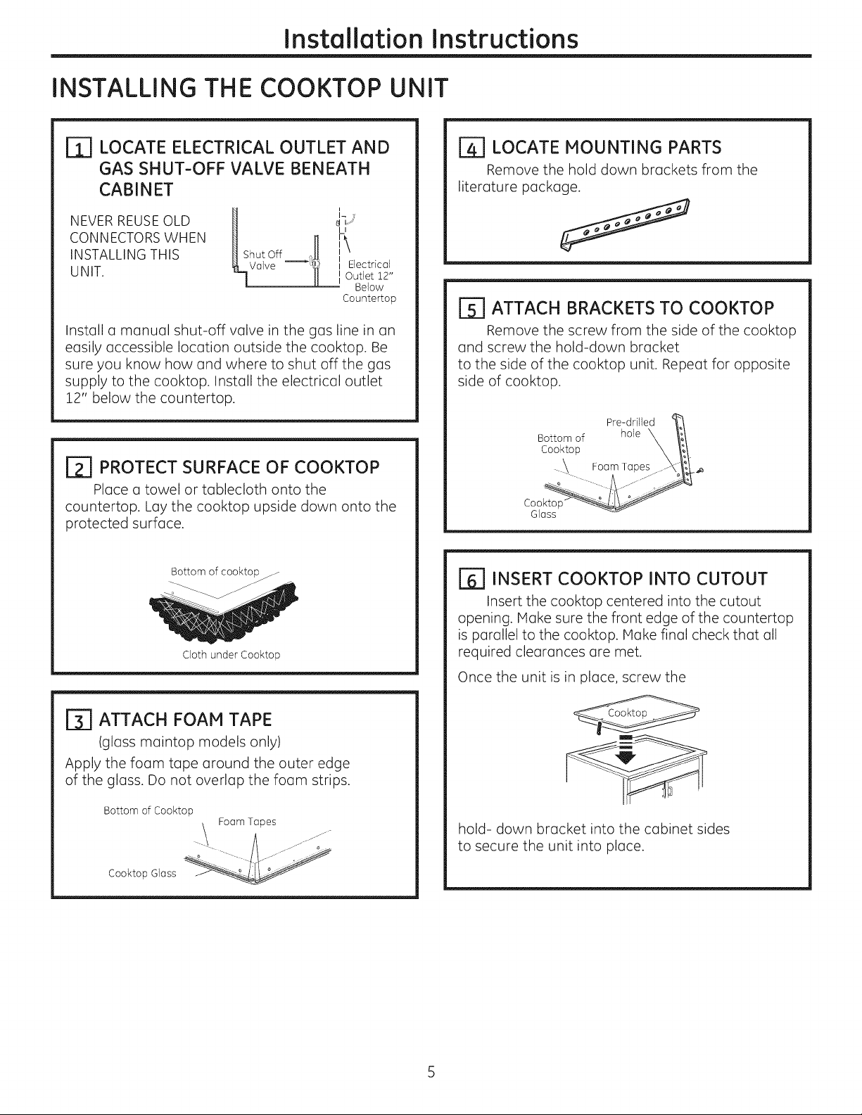
LOCATE ELECTRICAL OUTLET AND
rT]
GAS SHUT-OFF VALVE BENEATH
CABINET
_-] LOCATE MOUNTING PARTS
Remove the hold down brackets from the
literature package.
NEVER REUSEOLD
CONNECTORS WHEN
INSTALLING THIS
UNIT.
ShutOff _},H IF''
_Valve --][ j ElectricalOutlet 12"
_1 LJ
II
i
Below
Countertop
Install a manual shut-off valve in the gas line in an
easily accessible location outside the cooktop. Be
sure you know how and where to shut off the gas
supply to the cooktop. Install the electrical outlet
12" below the countertop.
[_] PROTECT SURFACE OF COOKTOP
Place a towel or tablecloth onto the
countertop. Lay the cooktop upside down onto the
protected surface.
Bottom of cooktop j
Cloth under Cooktop
r_ ATTACH BRACKETS TO COOKTOP
Remove the screw from the side of the cooktop
and screw the hold-down bracket
to the side of the cooktop unit. Repeat for opposite
side of cooktop.
Pre-drilled
Bottom of
Cooktop
Cookto
Glass
hole
[]_] INSERT COOKTOP INTO CUTOUT
Insert the cooktop centered into the cutout
opening. Make sure the front edge of the countertop
is parallel to the cooktop. Make final check that all
required clearances are met.
Once the unit is in place, screw the
[_ ATTACH FOAM TAPE
(glass maintop models only)
Apply the foam tape around the outer edge
of the glass. Do not overlap the foam strips.
Bottom of Cooktop
_. Foam Tapes
Cooktop Glass
hold- down bracket into the cabinet sides
to secure the unit into place.
Page 6
Installation Instructions
INSTALLATION--GAS CONNECTIONS
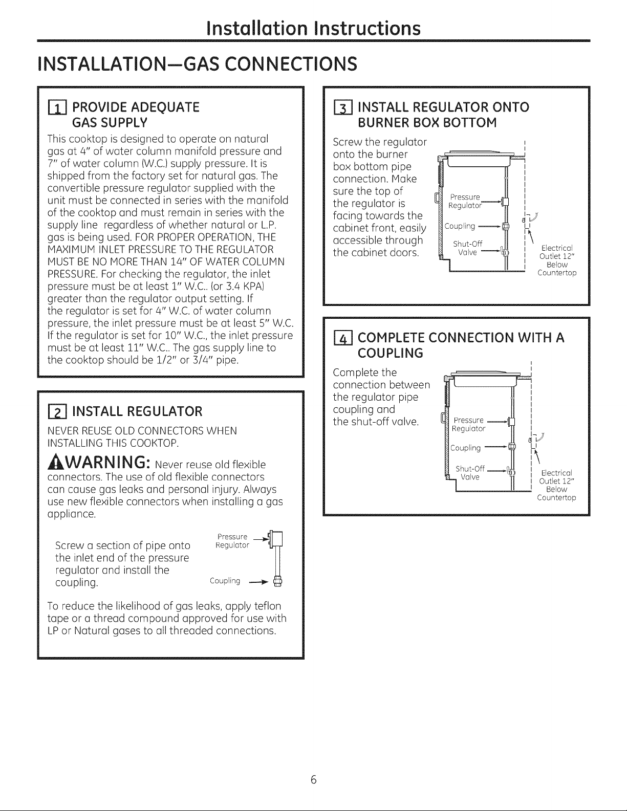
r_ PROVIDE ADEQUATE
GAS SUPPLY
This cooktop is designed to operate on natural
gas at 4" of water column manifold pressure and
7" of water column (W.C.) supply pressure. It is
shipped from the factory set for natural gas. The
convertible pressure regulator supplied with the
unit must be connected in series with the manifold
of the cooktop and must remain in series with the
supply line regardless of whether natural or L.P.
gas is being used. FOR PROPEROPERATION, THE
HAXIHUH INLET PRESSURETO THE REGULATOR
HUST BE NO HaRE THAN 24" OF WATER COLUHN
PRESSURE.For checking the regulator, the inlet
pressure must be at least 1" W.C.. (or 3.4 KPA)
greater than the regulator output setting. If
the regulator is set for 4" W.C. of water column
pressure, the inlet pressure must be at least 5" W.C.
If the regulator is set for 10" W.C., the inlet pressure
must be at least 11" W.C.. The gas supply line to
the cooktop should be 1/2" or 3/4" pipe.
r_ INSTALL REGULATOR
NEVER REUSEOLD CONNECTORS WHEN
INSTALLING THIS COOKTOP.
,AWARNING: Never reuse old flexible
connectors. The use of old flexible connectors
can cause gas leaks and personal injury. Always
use new flexible connectors when installing a gas
appliance.
r_ INSTALL REGULATOR ONTO
BURNER BOX BOTTOM
Screw the regulator
onto the burner
box bottom pipe
connection. Hake
sure the top of
the regulator is
facing towards the
cabinet front, easily
accessible through
the cabinet doors.
Pressure _1
Regulator--'---_l
Coupling l
LI
Ii Electrical
II Outlet 12"
I Below
Countertop
_] COMPLETE CONNECTION WITH A
COUPLING
Complete the
connection between
the regulator pipe
coupling and
the shut-off valve.
Pressure
Regulator
Coupling
I
U
i\
Shut-Off ___
Valve
II Electrical
I Outlet Z2"
I Below
Countertop
Screw a section of pipe onto
the inlet end of the pressure
regulator and install the
coupling.
To reduce the likelihood of gas leaks, apply teflon
tape or a thread compound approved for use with
LP or Natural gases to all threaded connections.
Pressure -_-_l
Regulator I
Coupling _
Page 7
Installation Instructions
[_ CHECK FOR LEAKS
Before testing for leaks, make sure all burner knobs
are in the OFF position.
After connecting the cooktop to gas, check system
for leaks with a manometer. If a manometer is not
available, turn the gas supply on to the cooktop
and use a liquid leak detector at all joints and
connections to check for leaks.
Tighten all connections if necessary to prevent gas
leakage in the cooktop or supply line.
DO NOT USE OPEN FLAHE TO CHECK FOR
LEAKS!
Disconnect the cooktop and its individual shut-off
valve from the gas supply piping system during any
pressure testing of that system at test pressures
greater than 1/2 psig (3.5 kPa).
Isolate the cooktop from the gas supply piping
system by closing its individual shut-off valve
during any pressure testing of the gas supply
system at test pressures equal to or less than 1/2
psig (3.5 kPa).
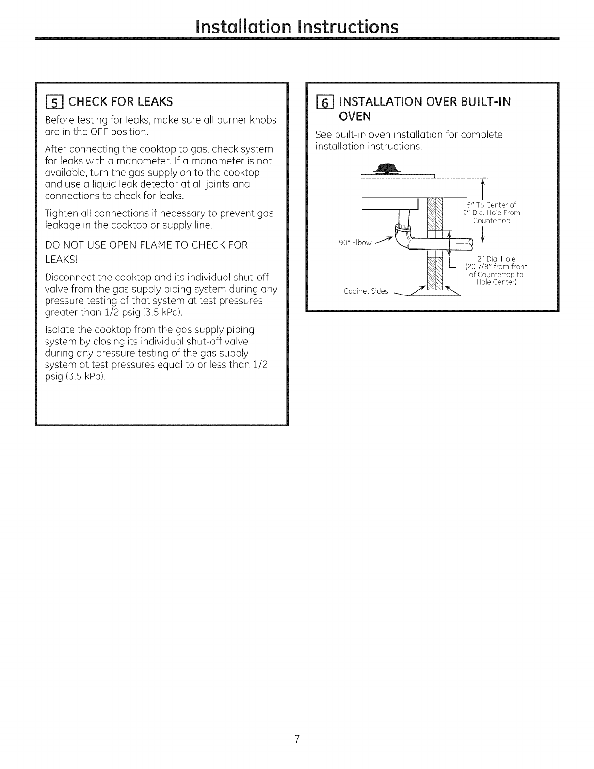
[_] INSTALLATION OVER BUILT-IN
OVEN
See built-in oven installation for complete
installation instructions.
t
J_ s"ToCenterof
I / _ 2" Dim.Hole From
, , , ,,I_ Countertop
90° Elbow ._ _...__
2" Dia. Hole
I_ (20 7/8" from front
of Countertop to
Cabinet Sides .... 7"
_.. Hole Center)
Page 8

Installation Instructions
INSTALLATION--ELECTRICAL CONNECTIONS
,WARNING - Disconnect all electrical
power at the main circuit breaker
or fuse box before installing.
EXTENSION CORDS
Becauseof potential safety hazards under certain
conditions, we strongly recommend against the
use of an extension cord. However, if you still
elect to use an extension cord, it isabsolutely
necessary that it be a UL listed ]-wire grounding
type appliance extension cord and that the
current carrying rating of the cord in amperes be
equivalent to or greater than the branch circuit
rating. Such extension cords are obtainable
through your local appliance dealer.
IMPORTANT: (Pleaseread carefully)FOR
PERSONAL SAFETY,THIS APPLIANCE MUST BE
PROPERLY GROUNDED.
[_ ELECTRICAL SUPPLY AND OUTLET
An adequate electrical supply and outlet must
be used to operate the electrical parts of your
cooktop.
[]
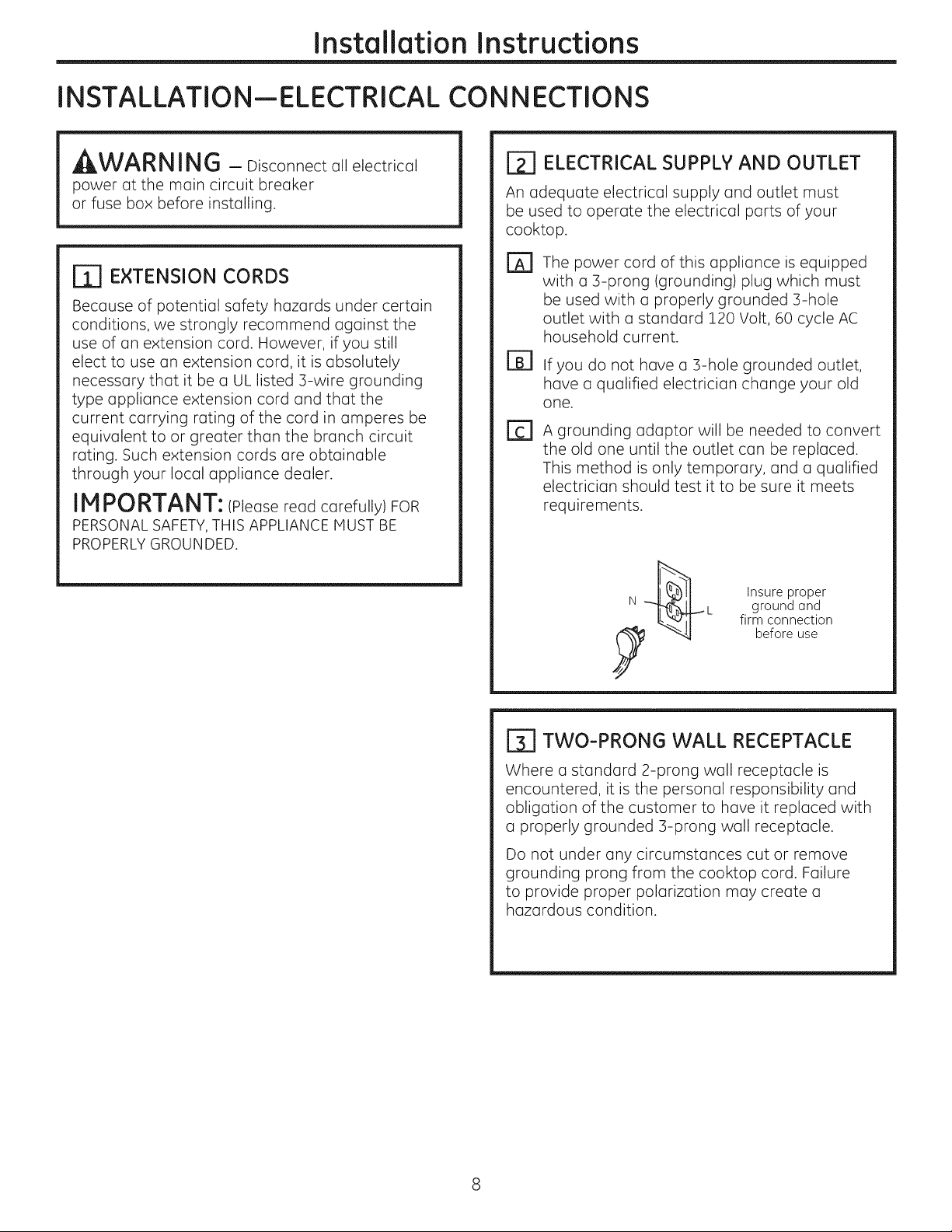
The power cord of this appliance is equipped
with a 3-prong (grounding) plug which must
be used with a properly grounded 3-hole
outlet with a standard 120 Volt, 60 cycle AC
household current.
B]
If you do not have a 3-hole grounded outlet,
have a qualified electrician change your old
one.
A grounding adaptor will be needed to convert
the old one until the outlet can be replaced.
This method is only temporary, and a qualified
electrician should test it to be sure it meets
requirements.
Insure proper
ground and
firm connection
before use
r_ TWO-PRONG WALL RECEPTACLE
Where a standard 2-prong wall receptacle is
encountered, it is the personal responsibility and
obligation of the customer to have it replaced with
a properly grounded 3-prong wall receptacle.
Do not under any circumstances cut or remove
grounding prong from the cooktop cord. Failure
to provide proper polarization may create a
hazardous condition.
Page 9
Installation Instructions
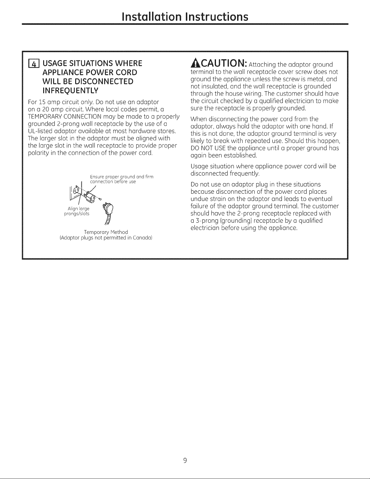
USAGE SITUATIONS WHERE
APPLIANCE POWER CORD
WILL BE DISCONNECTED
INFREQUENTLY
For 15 amp circuit only. Do not use an adaptor
on a 20 amp circuit. Where local codes permit, a
TEHPORARY CONNECTION may be made to a properly
grounded 2-prong wall receptacle by the use of o
UL-listed adaptor available ot most hardware stores.
The larger slot in the adaptor must be aligned with
the large slot in the wall receptacle to provide proper
polarity in the connection of the power cord.
Ensure proper ground and firm
connection before use
prongs/slots
Align Iorge
(Adoptor plugs not permitted in Conodo)
Temporary Method
A r'All_l,,_LI
AIIkL,/_LI/IUI_I: Attoching the odoptor ground
terminol to the woll receptocle cover screw does not
ground the opplionce unless the screw is metal, ond
not insuloted, ond the woll receptocle is grounded
through the house wiring. The customer should hove
the circuit checked by o quolified electricion to make
sure the receptacle is properly grounded.
When disconnecting the power cord from the
adaptor, always hold the adaptor with one hand. If
this is not done, the adaptor ground terminal is very
likely to break with repeated use. Should this happen,
DO NOT USE the appliance until a proper ground has
again been established.
Usage situation where appliance power cord will be
disconnected frequently.
Do not use on odoptor plug in these situotions
because disconnection of the power cord places
undue stroin on the odoptor ond leods to eventuol
foilure of the odoptor ground terminol. The customer
should hove the 2-prong receptocle reploced with
o 3-prong (grounding) receptocle by o quolified
electricion before using the opplionce.
Page 10
COOKTOP BURNERS
Installation Instructions
ASSEMBLING THE COOKTOP
BURNERS
The electrode of the spark igniter is exposed. Be
careful not to push any cooktop controls while the
top of the burner is removed.
Do not remove the top or touch the electrode
of any burner while another burner is turned on.
Electrical shock might result.
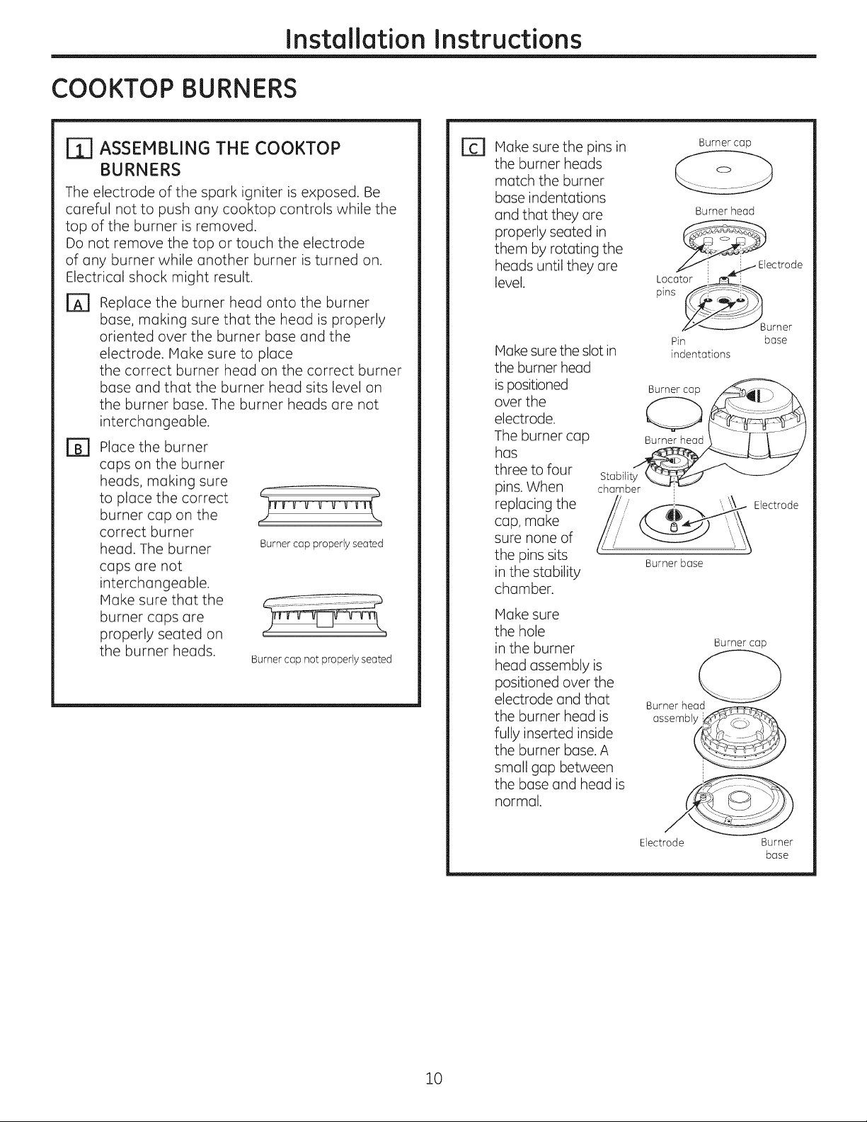
D Replace the burner head onto the burner
base, making sure that the head is properly
oriented over the burner base and the
electrode. Hake sure to place
the correct burner head on the correct burner
base and that the burner head sits level on
the burner base. The burner heads are not
interchangeable.
Place the burner
B]
caps on the burner
heads, making sure
to place the correct
burner cap on the
correct burner
head. The burner
caps are not
interchangeable.
Hake sure that the
burner caps are
properly seated on
the burner heads.
Burner cap properly seated
Burner cap not properly seated
Make sure the pins in
E]
the burner heads
match the burner
base indentations
and that they are
properly seated in
them by rotating the
heads until they are
level.
Make sure the slot in
the burner head
is positioned
over the
electrode.
The burner cap
has
three to four
pins. When
replacing the
cap, make
sure none of
the pins sits
in the stability
chamber.
Hake sure
the hole
in the burner
head assembly is
positioned over the
electrode and that
the burner head is
fully inserted inside
the burner base. A
small gap between
the base and head is
normal.
Burner cap
Burner head
_._ Electrode
Locatori_i
__Burner
Pin base
indentations
Burner cap
Burner head
assembl j__
10
Electrode Burner
base
Page 11

Installation Instructions
[_] CHECK IGNITERS
Operation of the electric igniters should be checked
after the cooktop and supply line have been
carefully checked for leaks and
the cooktop has been connected to the electrical
power.
On models so equipped, check to be sure the
cooktop is in the UNLOCKED position.
[] Push and turn a burner valve to the LITE
position. All spark igniters will make a series of
sparks (ticking sounds), but only the burner
turned to LITE will light.
* The burner should light when gas is
available to the burner.
* Once the burner lights, it should be turned
out of the LITE position.
[] Try each valve separately until all burners
have been checked.
BURNER IGNITION
| THE BURNER FLAMES
Turn each burner on. Flames should be blue in color
with no trace of yellow. The burner flames should
not flutter or blow away from the burner. The flame
should be no less than 1/4" on the lowest setting
and no greater than :1-1/2" on highest setting.
A! J n^_L,iL,r.
fyouattempttomeasure
the flame, please use caution. Burns could result.
1/4"to
i-i/2"
Burners should be checked frequently
Cooktop Burner
Cooktop Spark Ignition-When you turn
the cooktop knob to LITE,the spark igniter makes a
series of electric sparks (ticking sounds) which light
the burner. During a power failure, the burners will
not light automatically. In an emergency, a cooktop
burner may be lit with a match by following the
steps below.
_WARNING: Lighting gas burners with a
match is dangerous. You should match light the
cooktop burners only in
an emergency.
On models so equipped, check to be sure the
cooktop is in the UNLOCKED position.
rA1 Light a match and hold the flame near the
burner you want to light. Wooden matches
work best.
rB1 Push in and turn the control knob slowly. Be
sure you are turning the correct knob for the
burner you are lighting.
NOTE: If the burner does not light within five seconds,
turn the knob off and wait one minute before trying
again.
r_ BURNER GRATES
The four cooktop grates are designed for specific
positions. For maximum stability, these grates
should only be used in their proper position: they
should not be interchanged. For your convenience,
the undersides of the left and right grates are
marked "OUTSIDE" and "INSIDE". Make sure that the
side marked "OUTSIDE" is on the outer edge of your
cooktop.
"OUTSIDE.... INSIDE.... OUTSIDE"
edge edges edge
11
Page 12
Installation Instructions
OPERATION CHECKLIST
r_ Make sure all controls are left in the OFF r_
position. Check to be sure the cooktop is in the
UNLOCKED position (on models so equipped).
Make sure the flow of air to and from the
cooktop is unobstructed.
The serial plate for your cooktop is located on
the bottom of the burner box. In addition to the
model and serial numbers, it tells you the ratings
of the burners and the type of fuel and pressure
the cooktop was adjusted for when it left the
factory.
EEl
When ordering parts, always include the serial
number, model number and a code letter to
ensure proper replacement parts.
Recheck Steps:
Double check to make sure everything in this
guide has been completed. Rechecking steps
will ensure safe use of the cooktop.
12
Page 13

Installation Instructions
MAKING THE LP CONVERSION
IF SOLD OUTSIDE THE U.S. AND CANADA:
,_tWt'_K|'_ | |'_qtJ : Ifyou wish to use this product
with Liquefied Petroleum (LP)gas containing greater
than 10% butane, you must purchase a butane
conversion kit. To order, please call 1.888.664.8403 or
1.787.276.4051.
Model Butane Kit #
JGP940 WB28T10228
JGPZZ3 &
PGP943
JGP329 WB28T10234
WB28T10283
r_ SAFETY INFORMATION YOU
SHOULD KNOW
The pressure regulator and burner orifices are set
for natural gas. To use LP gas,
the regulator and burner orifices must
be converted. The LP orifice spuds for
the cooktop burners can be located in the literature
package attached to the regulator.
JLL,_L,I/IUi_I: The cooktop, as shipped from
the factory, is set for use with natural gas. If you
wish to use your cooktop with LPgas, you must
first replace the orifices and convert the pressure
regulator.
,AWARN ING: Thisconversion
must be performed by a qualifiedinstaller
or gas supplierinaccordance withthe
manufacturer'sinstructionsand allcodes
and requirementsofthe authorityhaving
jurisdiction. Failure to follow instructions could
result in serious injury or property damage. The
qualified agency performing this work assumes
responsibility for the conversion.
TOOLS YOU WILL NEED
FOR LP CONVERSION
Phillips-Head 7mm Nutdriver
Screwdriver
No.!5 Torx-Head
Pliers
Safety Glasses
ADJUST YOUR COOKTOP FOR USE
[2]
Driver
Small Flat-Head
Screwdriver (4mm or
5/]2" tip size,60mm
long)
WITH LP GAS
Disconnect all electrical power, at the main
circuit breaker or fuse box.
B]
Shut off the gas supply to the cooktop
by closing the manual shut-off valve.
[]
Adjust the pressure regulator, by the following
instructions:
* Unscrew the cap.
* Place your thumb against the flat side of the
spring retainer and press down to remove
the retainer.
* Carefully look at the spring retainer to locate
the NAT or LP position.
Cap Gasket
,_&L,_!,J|IUI_I: The following adjustments
must be made beforeturning
on the burner.Failuretodo so could resultin
seriousinjury.Be sure pressureregulatorhas been
convertedas describedinStep2.
13
NAT. Position
Position
Pressure Regulator
, Turn the spring retainer over so that LP is
showing on the bottom.
, Snap the retainer back into position.
, Screw the cap back onto the regulator.
Page 14
Installation Instructions
MAKING THE LP CONVERSION (CONT.)
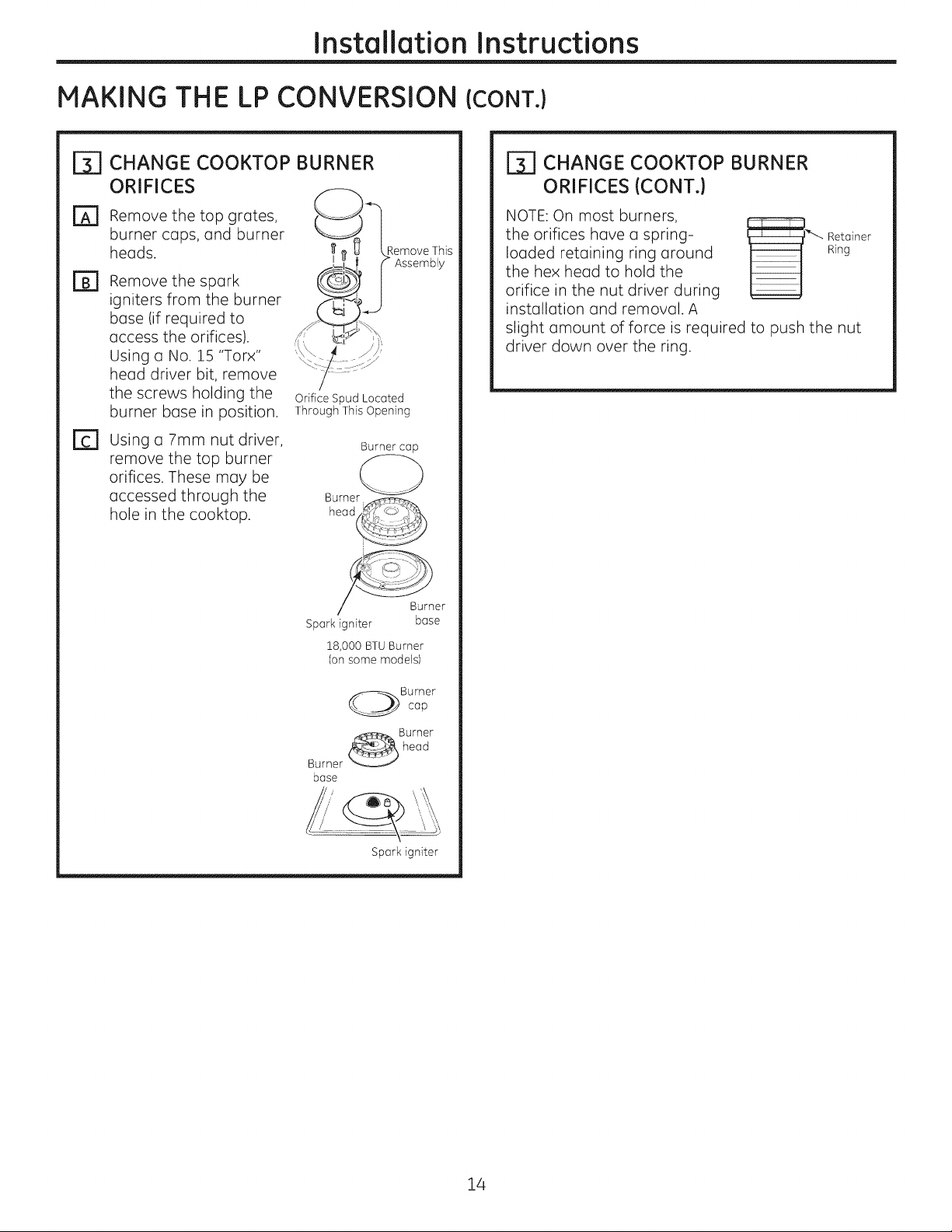
CHANGE COOKTOP BURNER
ORIFICES
Remove the top grates,
burner cops, and burner
heads.
Remove the spark
igniters from the burner
base (if required to
access the orifices).
Using o No. 15 "Torx"
head driver bit, remove
the screws holding the
burner bose in position.
Using a 7mm nut driver,
remove the top burner
orifices. These may be
accessed through the
hole in the cooktop.
I ue _ Remove This
I!=1_. (> Assembly
Orifice Spud Located
Through This Opening
/ Burner
Spark igniter base
18,000 BTUBurner
(on some models)
Burnercap
r_ CHANGE COOKTOP BURNER
ORIFICES (CONT.)
NOTE: On most burners,
the orifices have a spring-
loaded retaining ring around
the hex head to hold the
_ etainer
orifice in the nut driver during
installation and removal. A
slight amount of force is required to push the nut
driver down over the ring.
Ring
base
Burner
cap
Spark igniter
14
Page 15

Installation Instructions
CHANGE COOKTOP BURNER
ORIFICES (CONT.)
Locote the LP/Propone orifices shipped
inside the literoture pockoge. They
will have a digit number and the letter "L" on
the side. (Important: Sove the orifices
removed from the opplionce
for future use.)
Each orifice will show o series of engroved
morks, (I, II, III,X or none),
Iocoted on the top.
These morks denote the precise Iocotion of eoch
orifice to the cooktop burner.
Model Rear Left Front Left Front Right
Burner Burner Burner
JGP329 II II III
JGP940 III III X
JGP333 III II Replace: With:
PGP943 Main 175HXN-e 99HXL
Simmer 57N -e 34L
0000
15,000 BTU/HR Burner (onsome models)
O he 15,000 BTU/HRburner has two orifices with
NOTE: The moin orifice is Iocoted low in the center
of the burner while the simmer orifice is Iocoted
higher behind the center of the burner.
markings located in the sides only. (Seerating
plate on bottom of appliance).
orifice
Hain orifice
Simmel__i
Install the LP/Propone orifices in their precise
locations us noted in the illustrations above.
Return the natural gas orifices to the brocket
ond reottuch the brocket ond the instruction
sheet to the pressure regulator using the
screw removed previously.
Reploce the burner boses, heods, cops ond
[]
top grotes. (NOTE: When re-ottuchinq the
burner bases to loss to units tiqhten screws
to o maximum of 10 in.-Ibs torque.)
15
Page 16

Installation Instructions
MAKING THE LP CONVERSION (CONT.)
ADJUST BURNER FLAMES
Turn all burners full on and check the flames.
They should be blue in color with some yellow
tipping at the ends of the flame. Foreign
particles in the gas line may cause an orange
flame at first, but this will soon disappear.
NOTE:For the 15,000 BTU/HR burner (on some
models) the cooktop burner knob should be
turned to the setting before the lowest setting.
This will ensure that the entire burner is
operating.
r_ Turn the cooktop burner knob to the lowest
setting while observing the flame.
Adjust the low flame setting using the valve bypass
screw as follows:
Low-setting adjustments must be made with two
other burners in operation on a medium setting.
This prevents the low flame from being set too low,
resulting in the flame being extinguished when
other burners are turned on.
E] To adjust the flame, remove the knobs. Insert
a screwdriver through the access hole in valve
switch. Engage
adjustment screw in
valve. Refer to the
illustration below that
matches the adjustment
screw location for your
model.
rD] Make the adjustment by slowly turning the
screw until flame appearance is correct.
Note: Some models may contain a silicone shield
which covers the valve switch and access hole. A
flashlight may be required to locate the access hole. To
access the valve adjusting screw, push the screwdriver
through this shield. After adjustment, reseat the
shield around the switch hub with your fingers, after
withdrawinc the screwdriver.
Reseat silicone shield
CORRECT INCORRECT
r_ Testing Flame Stability:
Test 1 - Turn the knob from "HI" to the lowest
setting quickly. If the flame goes out
at the lowest setting, increase the
flame size and test again.
Test 2 -
With the burner on the lowest setting,
open and close the cabinet door
under the cooktop. If the flame is
extinguished by the air currents
created by the door movement,
increase the flame height and test
again.
If the flames were too _/_
small or fluttered, open
the valve more than
the original setting.
If the flames blew
away from the burner,
close the valve more
than the original
setting.
/only
r_ Flame Recheck:
After the adjustment is made, turn all burners off.
Ignite each burner individually. Observe the flame
at the "HI" position. Rotate the valve to the lowest
setting and be sure that the flame size decreases
as the valve is rotated counterclockwise.
TO CONVERT THE COOKTOP BACK TO NATURAL
GAS, REVERSETHE STEPSUNDER MAKING THE LP
CONVERSION.
Once the conversion is complete and checked
ok, fill out the LP sticker and include your name,
organization and date conversion was made. Apply
the sticker near the cooktop gas inlet opening to
alert others in the future that this appliance has
been converted to LP gas. If converting back to
natural gas from LP, please remove the sticker so
others know the appliance is set to use natural gas.
16
Page 17

I stallatio
30" SealedGasCooktop
I structio s
Questions?Call 800.GE.CARES(800.432.2737 or Visitour Website at:ge.com
In Canada, call 1.800.561.3344 or Visitour Website at: www.geappliances.ca
JGP329 JGP333, JGP940, PGP943
IN THE COMMONWEALTH OF
MASSACH USETTS:
, This product must be installed by a licensed
plumber or gas fitter.
, When using ball-type gas shut-off valves, they
shall be the T-handle type.
, A flexible gas connector, when used, must not
exceed 3 feet.
BEFORE YOU BEGIN
Read these instructions completely
and carefully.
.IMPORTANT - Savetheseinstructions
for local inspector's use.
, IMPORTANT - Observeallgoverning
codes and ordinances.
, Note to Installer- Be sure to leave these
instructions with the Consumer.
, Note to Consumer - Keep these instructions for
future reference.
i
FOR YOUR SAFETY:
,_WARNING - iftheinformation
in this manual is not followed exactly, o fire,
explosion or gas leak may result causing property
damage, personal injury or death.
Do not store or use gasoline or other flammable
vapors and liquids in the vicinity of this or any other
appliance!
WHAT TO DO IF YOU SMELL
GAS:
Do not try to light any appliance. Do not touch
any electrical switch; do not use any phone in
your building.
Immediately call your gas supplier from a
neighbor's phone. Follow the gas supplier's
instructions.
, If you cannot reach your gas supplier, call the fire
department.
Installation and service must be performed
by a qualified installer, service agency or
the gas supplier.
, Product failure due to improper installation is not
covered under the Warranty.
AWARNING - Thisappliancemust be
properlygrounded.
. IMPORTANT - Leak testingofthe
applianceshallbe conducted accordingto the
manufacturer's instructions.
, Proper installation is the responsibility of the
installer and product failure due to improper
installation is NOT covered under warranty.
WARN ING - Disconnectallelectrical
power at the main circuit breaker
or fuse box before installing.
31-i0835 (II-IIGE) i
This cooktop has been design certified
by CSA International. You'll find safety precautions
in your Owner's Manual.
Read them carefully.
Installation of this cooktop must conform with
local codes or in the absence of local codes with
the National Fuel Gas Code, ANSI Z223.1/NFPA
54-Latest edition.
Be sure your cooktop is installed properly by a
qualified installer or service technician.
To eliminate reaching over surface burners,
cabinet storage above burner should be avoided.
Do not install the unit near an outside door or
where a draft may affect its use.
Page 18

Installation Instructions
IMPORTANT SAFETY INSTRUCTIONS
ELECTRICAL REQUIREMENTS
This appliance must be supplied with the proper
voltage and frequency and connected to an
individual, properly grounded branch circuit,
protected by a circuit breaker or fuse having
amperage as noted on the rating plate.
We recommend you have the electrical wiring and
hookup of your cooktop connected by a qualified
electrician. After installation, have the electrician
show you where your main cooktop disconnect is
located.
Check with your local utilities for electrical codes
which apply in your area. Failure to wire your
cooktop according to governing codes could result
in a hazardous condition.
If there are no codes, your cooktop must be wired
and fused to meet the requirements
of the National Electrical Code, ANSI/NFPA No. 70--
Latest edition. You can get a copy
by writing:
National Fire Protection Association
Batterymarch Park
Quincy, P1A 02269
PARTS INCLUDED
2Screws
Foam Tape
MATERIALS YOU MAY NEED
Joint Sealant Pipe Fittings
CSA-Approved Flexible Gas Line
3/8" Min. ID, 1/2" NPTConnection,
3-foot Maximum Length (Massachusetts Only)
2 Hold
Down Brackets
Shut-Off Valve
In Canada your cooktop must be wired
and fused to meet the requirements of the
Canadian Electrical Code.
Be sure the installation of this product
in a mobile home conforms with the Manufactured
Home Construction and
Safety Standard, Title 24 CFR, Part 3280.
If this standard does not apply, you must follow
the standard for Manufactured Home Installations,
ANSI A225.1 and Manufactured Home Installations,
Sites and Communities and ANSI/NFPA 501A or
with local codes.
You can get a copy of the Federal Standard by
Writing:
Office of Mobile Home Standards
HUD Building
451 7th Street, S.W.
Washington, D.C. 24010
TOOLS YOU WILL NEED
FOR INSTALLATION
Pencil
Saber Saw
Phillips-Head
Screwdriver
Pipe Wrench
Ruler or Straightedge
!/8" Drill Bit & Electric or
Hand Drill
Safety Glasses
Page 19

Installation Instructions
PRE-INSTALLATION CHECKLIST
When preparing cooktop opening, make
[Z]
sure the inside of the cabinet and the
cooktop do not interfere with each other.
(See section on preparing the opening.)
Remove packaging materials, grote boxes,
@
regulator with literature, and literature
package from the cooktop before beginning
installation.
Foam_ _
Pac / _ _ _ _
Cooktop J
Package
Grate boxes
Remove Installation Instructions from
E1
literature pack and read them carefully
before you begin.
Be sure to place all literature, Use and Care,
Installations, etc. in a safe place for future
reference.
Hake sure you have all the tools and
El
materials you need before starting the
installation of the cooktop.
Your home must provide the adequate
El
electrical service needed to safely and
properly use your cooktop. (Refer to section
on electrical requirements.)
When installing your cooktop in your home,
El
make sure all local codes and ordinances
are followed exactly as stated.
Hake sure the wall coverings, countertop
[]
and cabinets around the cooktop can
withstand heat (up to 200°F) generated by
the cooktop.
Page 20

Instollotion Instructions
PREPARING THE OPENING
MAINTAIN THE FOLLOWING
MINIMUM CLEARANCE
DIMENSIONS
13" IVlAX.Depth of unprotected
6" MIN. clearance from
II cutout to side wall on the
overhead cabinets _
3-3/4" MIN.clearance from_
right of the unit
_18" HIN. height
f from countertop to
nearest cabinet on
either side of unit
NOTE: All gas cooktop models require 7/16"
free area below cooktop height to combustible
material.
ITI OVERALL COOKTOP DIMENSIONS
| RECOMMENDED GAS SUPPLY
LOCATION FROM BACKWALL
1" Min. From Backwall
Rec°mmended ii _ _:
gas supply
location 13-1/_
_ From Cutout
Center Line
[_] MAKE SURE WALL COVERINGS,
COUNTERTOP AND CABINETS
AROUND COOKTOP CAN
WITHSTAND HEAT {UP TO 200°F)
GENERATED BY COOKTOP
50" -'__ Glass Top models)
19-3/8" ._-_
21" (21-1/2" Max. for
[_ CUTOUT DIMENSIONS OF
COUNTERTOP
To ensure accuracy, it is best to make
o template when cutting the opening
in the counter.
_._ 28-1/2'
2-1/4" Min. Between -_--
cutout and the wall
behind the cooktop
! _ ofcut
2-1/2" Min. from
front edge of cutout
and front edge of
countertop
length -_--_¢ 14-1/4" :
19-5/8" width cut
Wall covering,
cabinets and
countertop must l
withstand heat I
Page 21

Installation Instructions
iNSTALLiNG THE COOKTOP UNiT
LOCATE ELECTRICAL OUTLET AND
rT]
GAS SHUT-OFF VALVE BENEATH
CABINET
_-] LOCATE MOUNTING PARTS
Remove the hold down brackets from the
literature package.
NEVER REUSEOLD
CONNECTORS WHEN
INSTALLING THIS
UNIT.
ShutOff _},H IF''
_Valve --][ j ElectricalOutlet 12"
_1 LJ
II
i
Below
Countertop
Install a manual shut-off valve in the gas line in an
easily accessible location outside the cooktop. Be
sure you know how and where to shut off the gas
supply to the cooktop. Install the electrical outlet
12" below the countertop.
[_] PROTECT SURFACE OF COOKTOP
Place a towel or tablecloth onto the
countertop. Lay the cooktop upside down onto the
protected surface.
Bottom of cooktop j
Cloth under Cooktop
r_ ATTACH BRACKETS TO COOKTOP
Remove the screw from the side of the cooktop
and screw the hold-down bracket
to the side of the cooktop unit. Repeat for opposite
side of cooktop.
Pre-drilled
Bottom of
Cooktop
Cookto
Glass
hole
[]_] INSERT COOKTOP INTO CUTOUT
Insert the cooktop centered into the cutout
opening. Make sure the front edge of the countertop
is parallel to the cooktop. Make final check that all
required clearances are met.
Once the unit is in place, screw the
[_ ATTACH FOAM TAPE
(glass maintop models only)
Apply the foam tape around the outer edge
of the glass. Do not overlap the foam strips.
Bottom of Cooktop
_. Foam Tapes
Cooktop Glass
hold- down bracket into the cabinet sides
to secure the unit into place.
Page 22

Installation Instructions
INSTALLATION--GAS CONNECTIONS
r_ PROVIDE ADEQUATE
GAS SUPPLY
This cooktop is designed to operate on natural
gas at 4" of water column manifold pressure and
7" of water column (W.C.) supply pressure. It is
shipped from the factory set for natural gas. The
convertible pressure regulator supplied with the
unit must be connected in series with the manifold
of the cooktop and must remain in series with the
supply line regardless of whether natural or L.P.
gas is being used. FOR PROPEROPERATION, THE
HAXIHUH INLET PRESSURETO THE REGULATOR
HUST BE NO HaRE THAN 24" OF WATER COLUHN
PRESSURE.For checking the regulator, the inlet
pressure must be at least 1" W.C.. (or 3.4 KPA)
greater than the regulator output setting. If
the regulator is set for 4" W.C. of water column
pressure, the inlet pressure must be at least 5" W.C.
If the regulator is set for 10" W.C., the inlet pressure
must be at least 11" W.C.. The gas supply line to
the cooktop should be 1/2" or 3/4" pipe.
r_ INSTALL REGULATOR
NEVER REUSEOLD CONNECTORS WHEN
INSTALLING THIS COOKTOP.
,AWARNING: Never reuse old flexible
connectors. The use of old flexible connectors
can cause gas leaks and personal injury. Always
use new flexible connectors when installing a gas
appliance.
r_ INSTALL REGULATOR ONTO
BURNER BOX BOTTOM
Screw the regulator
onto the burner
box bottom pipe
connection. Hake
sure the top of
the regulator is
facing towards the
cabinet front, easily
accessible through
the cabinet doors.
Pressure _1
Regulator--'---_l
Coupling l
LI
Ii Electrical
II Outlet 12"
I Below
Countertop
_] COMPLETE CONNECTION WITH A
COUPLING
Complete the
connection between
the regulator pipe
coupling and
the shut-off valve.
Pressure
Regulator
Coupling
I
U
i\
Shut-Off ___
Valve
II Electrical
I Outlet Z2"
I Below
Countertop
Screw a section of pipe onto
the inlet end of the pressure
regulator and install the
coupling.
To reduce the likelihood of gas leaks, apply teflon
tape or a thread compound approved for use with
LP or Natural gases to all threaded connections.
Pressure -_-_l
Regulator I
Coupling _
Page 23

Installation Instructions
[_ CHECK FOR LEAKS
Before testing for leaks, make sure all burner knobs
are in the OFF position.
After connecting the cooktop to gas, check system
for leaks with a manometer. If a manometer is not
available, turn the gas supply on to the cooktop
and use a liquid leak detector at all joints and
connections to check for leaks.
Tighten all connections if necessary to prevent gas
leakage in the cooktop or supply line.
DO NOT USE OPEN FLAHE TO CHECK FOR
LEAKS!
Disconnect the cooktop and its individual shut-off
valve from the gas supply piping system during any
pressure testing of that system at test pressures
greater than 1/2 psig (3.5 kPa).
Isolate the cooktop from the gas supply piping
system by closing its individual shut-off valve
during any pressure testing of the gas supply
system at test pressures equal to or less than 1/2
psig (3.5 kPa).
[_] INSTALLATION OVER BUILT-IN
OVEN
See built-in oven installation for complete
installation instructions.
t
J_ s"ToCenterof
I / _ 2" Dim.Hole From
, , , ,,I_ Countertop
90° Elbow ._ _...__
2" Dia. Hole
I_ (20 7/8" from front
of Countertop to
Cabinet Sides .... 7"
_.. Hole Center)
Page 24
Installation Instructions
INSTALLATION--ELECTRICAL CONNECTIONS
,WARNING - Disconnect all electrical
power at the main circuit breaker
or fuse box before installing.
EXTENSION CORDS
Becauseof potential safety hazards under certain
conditions, we strongly recommend against the
use of an extension cord. However, if you still
elect to use an extension cord, it isabsolutely
necessary that it be a UL listed ]-wire grounding
type appliance extension cord and that the
current carrying rating of the cord in amperes be
equivalent to or greater than the branch circuit
rating. Such extension cords are obtainable
through your local appliance dealer.
IMPORTANT: (Pleaseread carefully)FOR
PERSONAL SAFETY,THIS APPLIANCE MUST BE
PROPERLY GROUNDED.
[_ ELECTRICAL SUPPLY AND OUTLET
An adequate electrical supply and outlet must
be used to operate the electrical parts of your
cooktop.
[]
The power cord of this appliance is equipped
with a 3-prong (grounding) plug which must
be used with a properly grounded 3-hole
outlet with a standard 120 Volt, 60 cycle AC
household current.
B]
If you do not have a 3-hole grounded outlet,
have a qualified electrician change your old
one.
A grounding adaptor will be needed to convert
the old one until the outlet can be replaced.
This method is only temporary, and a qualified
electrician should test it to be sure it meets
requirements.
Insure proper
ground and
firm connection
before use
r_ TWO-PRONG WALL RECEPTACLE
Where a standard 2-prong wall receptacle is
encountered, it is the personal responsibility and
obligation of the customer to have it replaced with
a properly grounded 3-prong wall receptacle.
Do not under any circumstances cut or remove
grounding prong from the cooktop cord. Failure
to provide proper polarization may create a
hazardous condition.
Page 25

Installation Instructions
USAGE SITUATIONS WHERE
APPLIANCE POWER CORD
WILL BE DISCONNECTED
INFREQUENTLY
For 15 amp circuit only. Do not use an adaptor
on a 20 amp circuit. Where local codes permit, a
TEHPORARY CONNECTION may be made to a properly
grounded 2-prong wall receptacle by the use of o
UL-listed adaptor available ot most hardware stores.
The larger slot in the adaptor must be aligned with
the large slot in the wall receptacle to provide proper
polarity in the connection of the power cord.
Ensure proper ground and firm
connection before use
prongs/slots
Align Iorge
(Adoptor plugs not permitted in Conodo)
Temporary Method
A r'All_l,,_LI
AIIkL,/_LI/IUI_I: Attoching the odoptor ground
terminol to the woll receptocle cover screw does not
ground the opplionce unless the screw is metal, ond
not insuloted, ond the woll receptocle is grounded
through the house wiring. The customer should hove
the circuit checked by o quolified electricion to make
sure the receptacle is properly grounded.
When disconnecting the power cord from the
adaptor, always hold the adaptor with one hand. If
this is not done, the adaptor ground terminal is very
likely to break with repeated use. Should this happen,
DO NOT USE the appliance until a proper ground has
again been established.
Usage situation where appliance power cord will be
disconnected frequently.
Do not use on odoptor plug in these situotions
because disconnection of the power cord places
undue stroin on the odoptor ond leods to eventuol
foilure of the odoptor ground terminol. The customer
should hove the 2-prong receptocle reploced with
o 3-prong (grounding) receptocle by o quolified
electricion before using the opplionce.
Page 26

COOKTOP BURNERS
Installation Instructions
ASSEMBLING THE COOKTOP
BURNERS
The electrode of the spark igniter is exposed. Be
careful not to push any cooktop controls while the
top of the burner is removed.
Do not remove the top or touch the electrode
of any burner while another burner is turned on.
Electrical shock might result.
D Replace the burner head onto the burner
base, making sure that the head is properly
oriented over the burner base and the
electrode. Hake sure to place
the correct burner head on the correct burner
base and that the burner head sits level on
the burner base. The burner heads are not
interchangeable.
Place the burner
B]
caps on the burner
heads, making sure
to place the correct
burner cap on the
correct burner
head. The burner
caps are not
interchangeable.
Hake sure that the
burner caps are
properly seated on
the burner heads.
Burner cap properly seated
Burner cap not properly seated
Make sure the pins in
E]
the burner heads
match the burner
base indentations
and that they are
properly seated in
them by rotating the
heads until they are
level.
Make sure the slot in
the burner head
is positioned
over the
electrode.
The burner cap
has
three to four
pins. When
replacing the
cap, make
sure none of
the pins sits
in the stability
chamber.
Hake sure
the hole
in the burner
head assembly is
positioned over the
electrode and that
the burner head is
fully inserted inside
the burner base. A
small gap between
the base and head is
normal.
Burner cap
Burner head
_._ Electrode
Locatori_i
__Burner
Pin base
indentations
Burner cap
Burner head
assembl j__
10
Electrode Burner
base
Page 27

Installation Instructions
[_] CHECK IGNITERS
Operation of the electric igniters should be checked
after the cooktop and supply line have been
carefully checked for leaks and
the cooktop has been connected to the electrical
power.
On models so equipped, check to be sure the
cooktop is in the UNLOCKED position.
[] Push and turn a burner valve to the LITE
position. All spark igniters will make a series of
sparks (ticking sounds), but only the burner
turned to LITE will light.
* The burner should light when gas is
available to the burner.
* Once the burner lights, it should be turned
out of the LITE position.
[] Try each valve separately until all burners
have been checked.
BURNER IGNITION
| THE BURNER FLAMES
Turn each burner on. Flames should be blue in color
with no trace of yellow. The burner flames should
not flutter or blow away from the burner. The flame
should be no less than 1/4" on the lowest setting
and no greater than :1-1/2" on highest setting.
A! J n^_L,iL,r.
fyouattempttomeasure
the flame, please use caution. Burns could result.
1/4"to
i-i/2"
Burners should be checked frequently
Cooktop Burner
Cooktop Spark Ignition-When you turn
the cooktop knob to LITE,the spark igniter makes a
series of electric sparks (ticking sounds) which light
the burner. During a power failure, the burners will
not light automatically. In an emergency, a cooktop
burner may be lit with a match by following the
steps below.
_WARNING: Lighting gas burners with a
match is dangerous. You should match light the
cooktop burners only in
an emergency.
On models so equipped, check to be sure the
cooktop is in the UNLOCKED position.
rA1 Light a match and hold the flame near the
burner you want to light. Wooden matches
work best.
rB1 Push in and turn the control knob slowly. Be
sure you are turning the correct knob for the
burner you are lighting.
NOTE: If the burner does not light within five seconds,
turn the knob off and wait one minute before trying
again.
r_ BURNER GRATES
The four cooktop grates are designed for specific
positions. For maximum stability, these grates
should only be used in their proper position: they
should not be interchanged. For your convenience,
the undersides of the left and right grates are
marked "OUTSIDE" and "INSIDE". Make sure that the
side marked "OUTSIDE" is on the outer edge of your
cooktop.
"OUTSIDE.... INSIDE.... OUTSIDE"
edge edges edge
11
Page 28

Installation Instructions
OPERATION CHECKLIST
r_ Make sure all controls are left in the OFF r_
position. Check to be sure the cooktop is in the
UNLOCKED position (on models so equipped).
Make sure the flow of air to and from the
cooktop is unobstructed.
The serial plate for your cooktop is located on
the bottom of the burner box. In addition to the
model and serial numbers, it tells you the ratings
of the burners and the type of fuel and pressure
the cooktop was adjusted for when it left the
factory.
EEl
When ordering parts, always include the serial
number, model number and a code letter to
ensure proper replacement parts.
Recheck Steps:
Double check to make sure everything in this
guide has been completed. Rechecking steps
will ensure safe use of the cooktop.
12
Page 29

Installation Instructions
MAKING THE LP CONVERSION
IF SOLD OUTSIDE THE U.S. AND CANADA:
,_tWt'_K|'_ | |'_qtJ : Ifyou wish to use this product
with Liquefied Petroleum (LP)gas containing greater
than 10% butane, you must purchase a butane
conversion kit. To order, please call 1.888.664.8403 or
1.787.276.4051.
Model Butane Kit #
JGP940 WB28T10228
JGPZZ3 &
PGP943
JGP329 WB28T10234
WB28T10283
r_ SAFETY INFORMATION YOU
SHOULD KNOW
The pressure regulator and burner orifices are set
for natural gas. To use LP gas,
the regulator and burner orifices must
be converted. The LP orifice spuds for
the cooktop burners can be located in the literature
package attached to the regulator.
JLL,_L,I/IUi_I: The cooktop, as shipped from
the factory, is set for use with natural gas. If you
wish to use your cooktop with LPgas, you must
first replace the orifices and convert the pressure
regulator.
,AWARN ING: Thisconversion
must be performed by a qualifiedinstaller
or gas supplierinaccordance withthe
manufacturer'sinstructionsand allcodes
and requirementsofthe authorityhaving
jurisdiction. Failure to follow instructions could
result in serious injury or property damage. The
qualified agency performing this work assumes
responsibility for the conversion.
TOOLS YOU WILL NEED
FOR LP CONVERSION
Phillips-Head 7mm Nutdriver
Screwdriver
No.!5 Torx-Head
Pliers
Safety Glasses
ADJUST YOUR COOKTOP FOR USE
[2]
Driver
Small Flat-Head
Screwdriver (4mm or
5/]2" tip size,60mm
long)
WITH LP GAS
Disconnect all electrical power, at the main
circuit breaker or fuse box.
B]
Shut off the gas supply to the cooktop
by closing the manual shut-off valve.
[]
Adjust the pressure regulator, by the following
instructions:
* Unscrew the cap.
* Place your thumb against the flat side of the
spring retainer and press down to remove
the retainer.
* Carefully look at the spring retainer to locate
the NAT or LP position.
Cap Gasket
,_&L,_!,J|IUI_I: The following adjustments
must be made beforeturning
on the burner.Failuretodo so could resultin
seriousinjury.Be sure pressureregulatorhas been
convertedas describedinStep2.
13
NAT. Position
Position
Pressure Regulator
, Turn the spring retainer over so that LP is
showing on the bottom.
, Snap the retainer back into position.
, Screw the cap back onto the regulator.
Page 30

Installation Instructions
MAKING THE LP CONVERSION (CONT.)
CHANGE COOKTOP BURNER
ORIFICES
Remove the top grates,
burner cops, and burner
heads.
Remove the spark
igniters from the burner
base (if required to
access the orifices).
Using o No. 15 "Torx"
head driver bit, remove
the screws holding the
burner bose in position.
Using a 7mm nut driver,
remove the top burner
orifices. These may be
accessed through the
hole in the cooktop.
I ue _ Remove This
I!=1_. (> Assembly
Orifice Spud Located
Through This Opening
/ Burner
Spark igniter base
18,000 BTUBurner
(on some models)
Burnercap
r_ CHANGE COOKTOP BURNER
ORIFICES (CONT.)
NOTE: On most burners,
the orifices have a spring-
loaded retaining ring around
the hex head to hold the
_ etainer
orifice in the nut driver during
installation and removal. A
slight amount of force is required to push the nut
driver down over the ring.
Ring
base
Burner
cap
Spark igniter
14
Page 31

Installation Instructions
CHANGE COOKTOP BURNER
ORIFICES (CONT.)
Locote the LP/Propone orifices shipped
inside the literoture pockoge. They
will have a digit number and the letter "L" on
the side. (Important: Sove the orifices
removed from the opplionce
for future use.)
Each orifice will show o series of engroved
morks, (I, II, III,X or none),
Iocoted on the top.
These morks denote the precise Iocotion of eoch
orifice to the cooktop burner.
Model Rear Left Front Left Front Right
Burner Burner Burner
JGP329 II II III
JGP940 III III X
JGP333 III II Replace: With:
PGP943 Main 175HXN-e 99HXL
Simmer 57N -e 34L
0000
15,000 BTU/HR Burner (onsome models)
O he 15,000 BTU/HRburner has two orifices with
NOTE: The moin orifice is Iocoted low in the center
of the burner while the simmer orifice is Iocoted
higher behind the center of the burner.
markings located in the sides only. (Seerating
plate on bottom of appliance).
orifice
Hain orifice
Simmel__i
Install the LP/Propone orifices in their precise
locations us noted in the illustrations above.
Return the natural gas orifices to the brocket
ond reottuch the brocket ond the instruction
sheet to the pressure regulator using the
screw removed previously.
Reploce the burner boses, heods, cops ond
[]
top grotes. (NOTE: When re-ottuchinq the
burner bases to loss to units tiqhten screws
to o maximum of 10 in.-Ibs torque.)
15
Page 32

Installation Instructions
MAKING THE LP CONVERSION (CONT.)
ADJUST BURNER FLAMES
Turn all burners full on and check the flames.
They should be blue in color with some yellow
tipping at the ends of the flame. Foreign
particles in the gas line may cause an orange
flame at first, but this will soon disappear.
NOTE:For the 15,000 BTU/HR burner (on some
models) the cooktop burner knob should be
turned to the setting before the lowest setting.
This will ensure that the entire burner is
operating.
r_ Turn the cooktop burner knob to the lowest
setting while observing the flame.
Adjust the low flame setting using the valve bypass
screw as follows:
Low-setting adjustments must be made with two
other burners in operation on a medium setting.
This prevents the low flame from being set too low,
resulting in the flame being extinguished when
other burners are turned on.
E] To adjust the flame, remove the knobs. Insert
a screwdriver through the access hole in valve
switch. Engage
adjustment screw in
valve. Refer to the
illustration below that
matches the adjustment
screw location for your
model.
rD] Make the adjustment by slowly turning the
screw until flame appearance is correct.
Note: Some models may contain a silicone shield
which covers the valve switch and access hole. A
flashlight may be required to locate the access hole. To
access the valve adjusting screw, push the screwdriver
through this shield. After adjustment, reseat the
shield around the switch hub with your fingers, after
withdrawinc the screwdriver.
Reseat silicone shield
CORRECT INCORRECT
r_ Testing Flame Stability:
Test 1 - Turn the knob from "HI" to the lowest
setting quickly. If the flame goes out
at the lowest setting, increase the
flame size and test again.
Test 2 -
With the burner on the lowest setting,
open and close the cabinet door
under the cooktop. If the flame is
extinguished by the air currents
created by the door movement,
increase the flame height and test
again.
If the flames were too _/_
small or fluttered, open
the valve more than
the original setting.
If the flames blew
away from the burner,
close the valve more
than the original
setting.
/only
r_ Flame Recheck:
After the adjustment is made, turn all burners off.
Ignite each burner individually. Observe the flame
at the "HI" position. Rotate the valve to the lowest
setting and be sure that the flame size decreases
as the valve is rotated counterclockwise.
TO CONVERT THE COOKTOP BACK TO NATURAL
GAS, REVERSETHE STEPSUNDER MAKING THE LP
CONVERSION.
Once the conversion is complete and checked
ok, fill out the LP sticker and include your name,
organization and date conversion was made. Apply
the sticker near the cooktop gas inlet opening to
alert others in the future that this appliance has
been converted to LP gas. If converting back to
natural gas from LP, please remove the sticker so
others know the appliance is set to use natural gas.
16
 Loading...