

Page 1
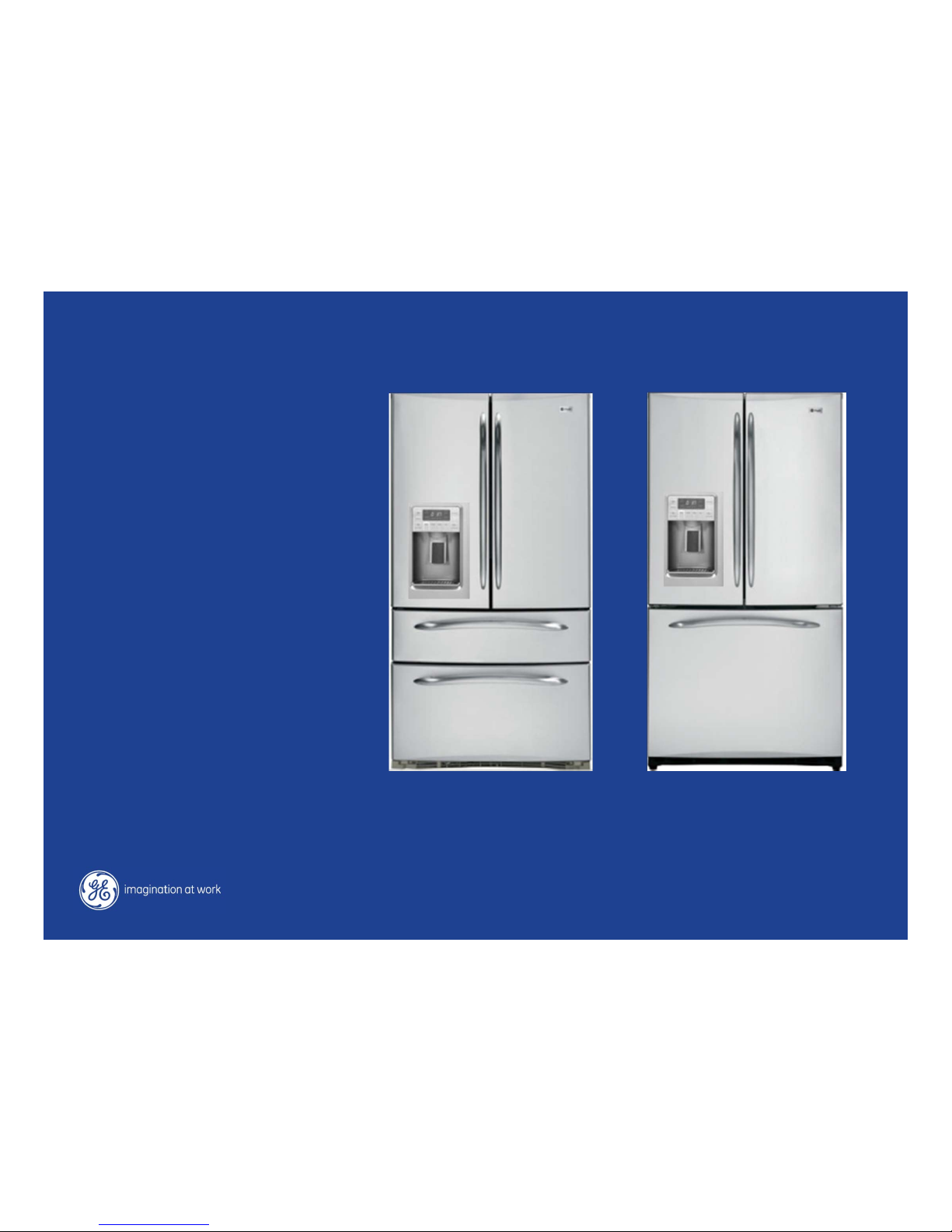
Bottom Freezer with Ice & Water in Door
PGCS1R
PFCF1R
PFSS5R
PGSS5R
BJ 5/11
Page 2

IMPORTANT SAFETY NOTICE
The information in this presentation is intended for use by individuals
possessing adequate backgrounds of electrical, electronic, &
mechanical experience. Any attempt to repair a major appliance may
result in personal injury & property damage. The manufacturer or seller
cannot be responsible for the interpretation of this information, nor can it
assume any liability in connection with its use.
WARNING
To avoid personal injury, disconnect power before servicing this product.
If electrical power is required for diagnosis or test purposes, disconnect
the power immediately after performing the necessary checks.
RECONNECT ALL GROUNDING DEVICES
If grounding wires, screws, straps, clips, nuts, or washers used to
complete a path to ground are removed for service, they must be
returned to their original position & properly fastened.
Page 3
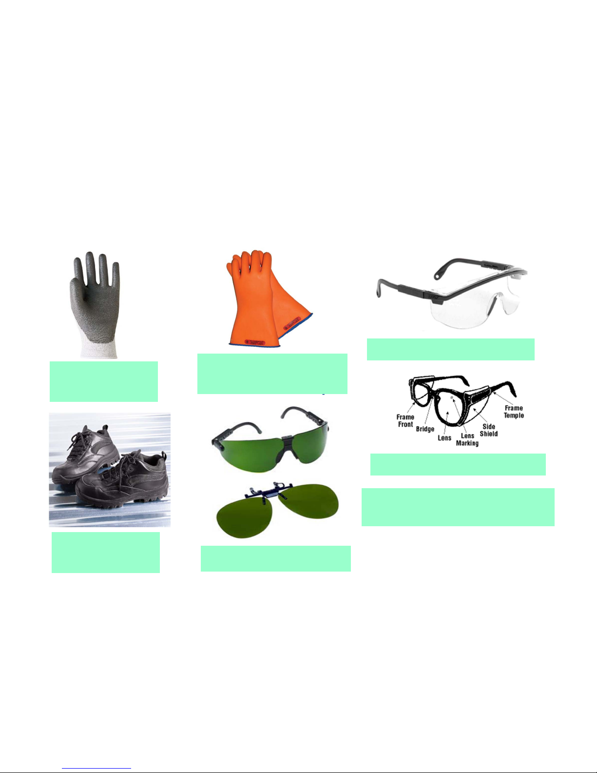
Dyneema®Cut
Resistant Glove
Dyneema®Cut
Resistant Glove
Safety Glasses must be
ANSI Z87.1-2003 compliant
Safety Glasses must be
ANSI Z87.1-2003 compliant
Prescription Safety GlassesPrescription Safety Glasses
Plano Type Safety GlassesPlano Type Safety Glasses
Steel Toe Work
Boot
Steel Toe Work
Boot
Electrically Rated Glove
and Dyneema®Cut
Resistant Glove Keeper
Electrically Rated Glove
and Dyneema®Cut
Resistant Glove Keeper
Brazing GlassesBrazing Glasses
GE Factory Service Employees are required to use safety glasses with
side shields, safety gloves & steel toe shoes for all repairs.
Page 4
Copyright General Electric 2011
Page 5
Copyright General Electric 2011
Key selling messages:
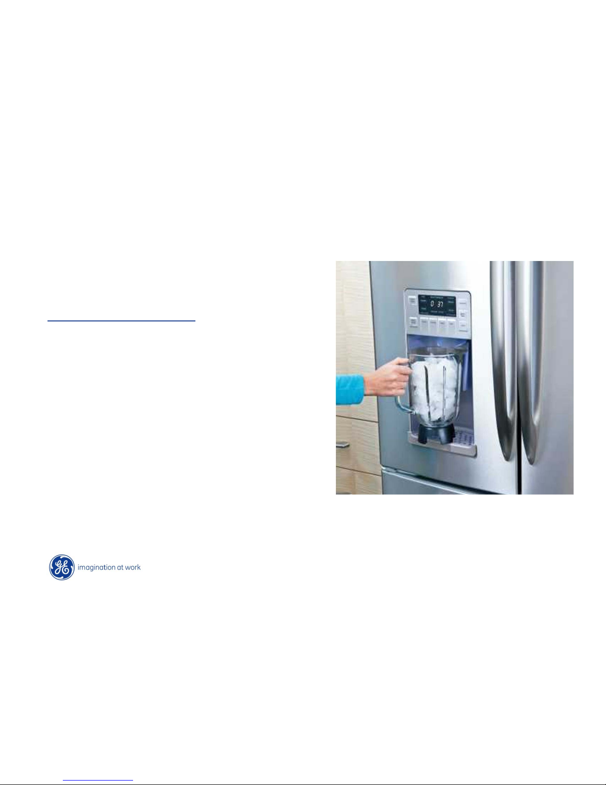
• GE’s Tallest Dispenser
• Zero Space - Pin-Point LED Lighting
• Large, Easy to Read / Use Display
• Shelf Management System (Up to 5)
• 8 Models
Marketing Features
Page 6
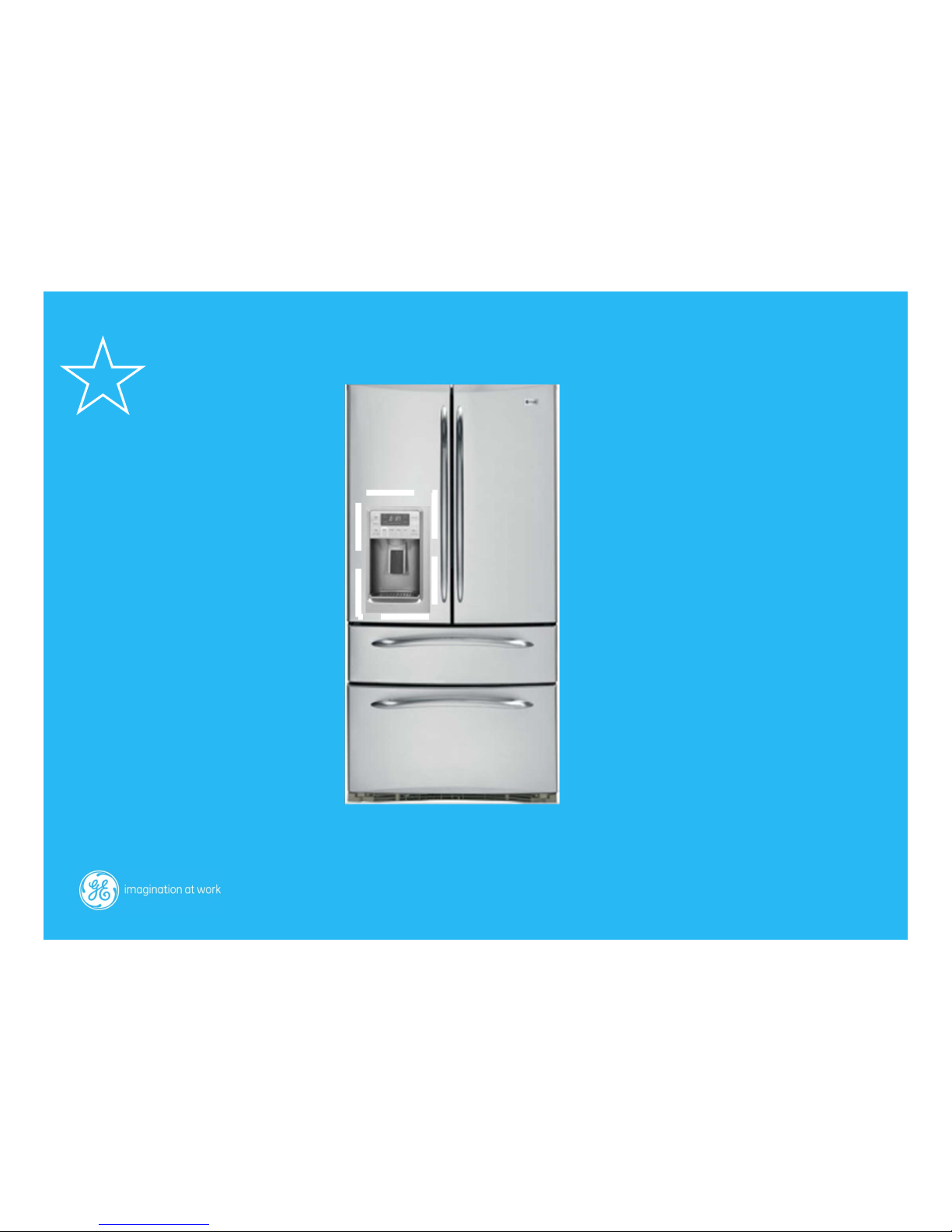
New Ice & Water Section
Page 7
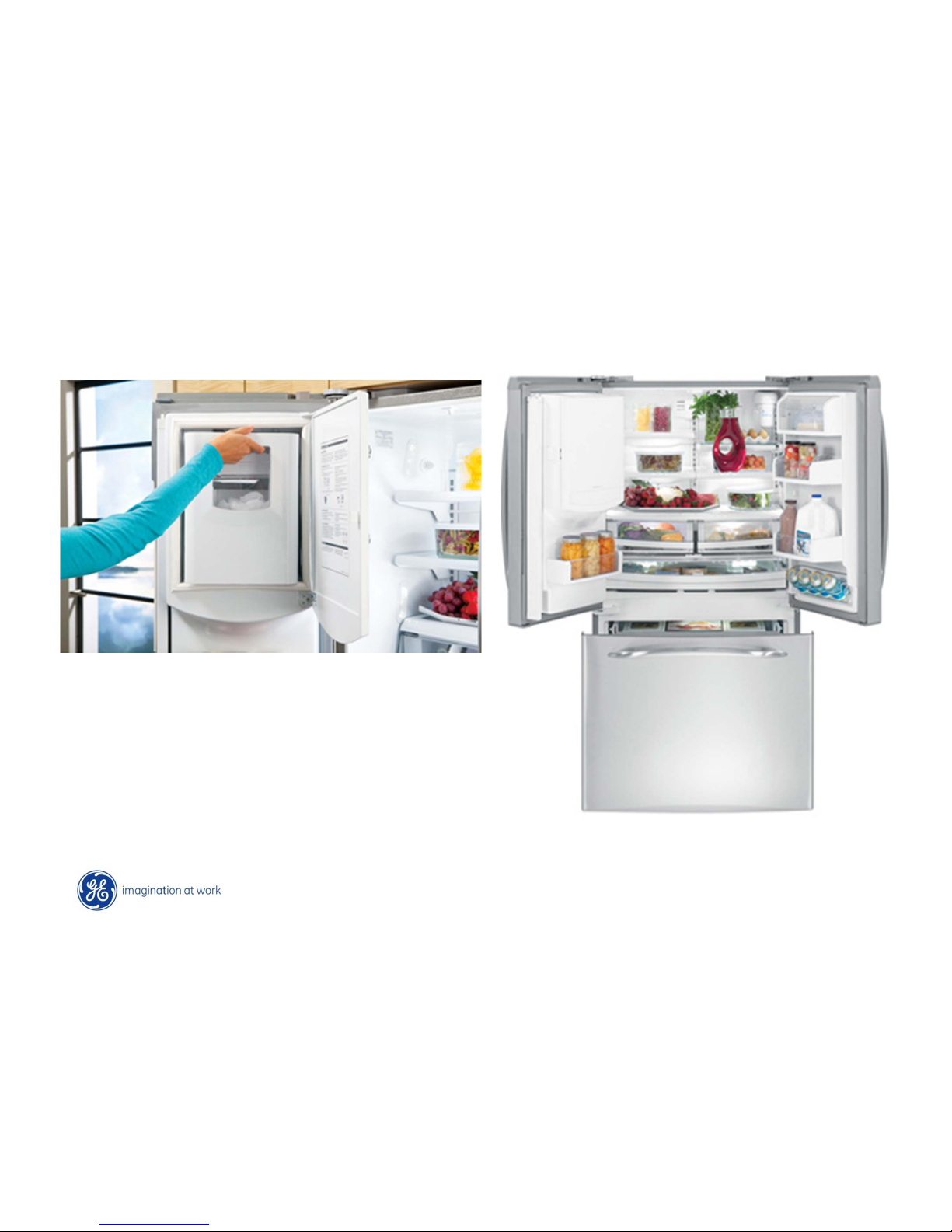
Copyright General Electric 2011
New Ice and Water in Door
Lift slightly “up” to remove bucket
Page 8
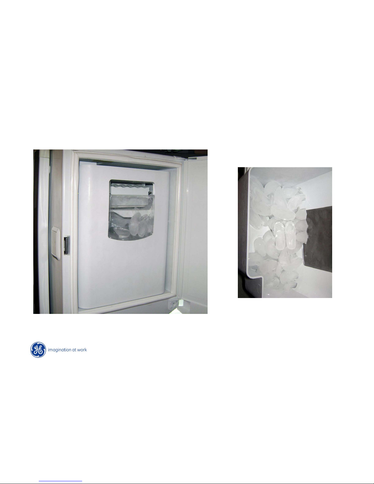
Copyright General Electric 2011
Bucket holds approximately 4 lbs
Ice Operation
Page 9
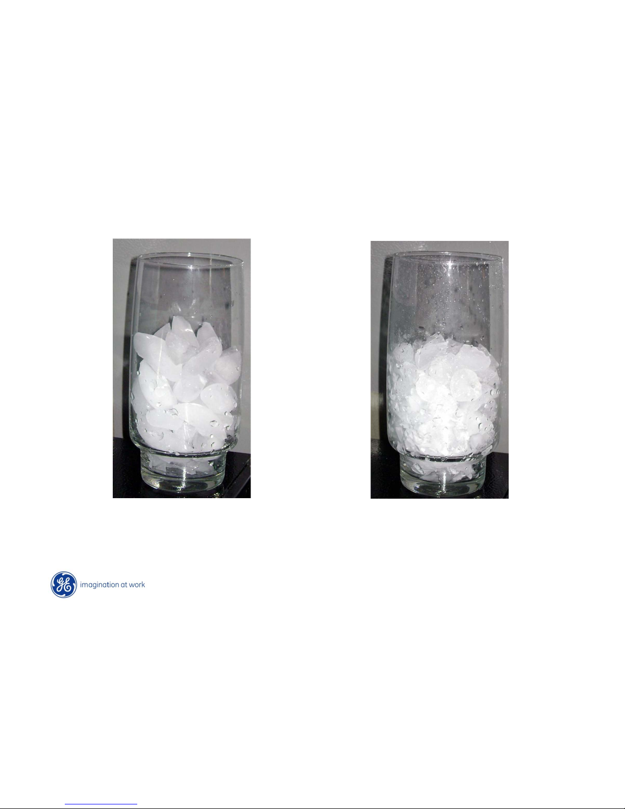
Copyright General Electric 2011
Cubes
Crushed
Ice Operation
Page 10
Copyright General Electric 2011
Ice Operation – Basic Logic
The new BM Ice in Door model has multiple and unique logic and calculations that are
accomplished with the board, the control settings, and feedback from thermistors.
However, the new ice door does not have its own thermistor and therefore calculations
are accomplished with input from the FF and FZ thermistors.
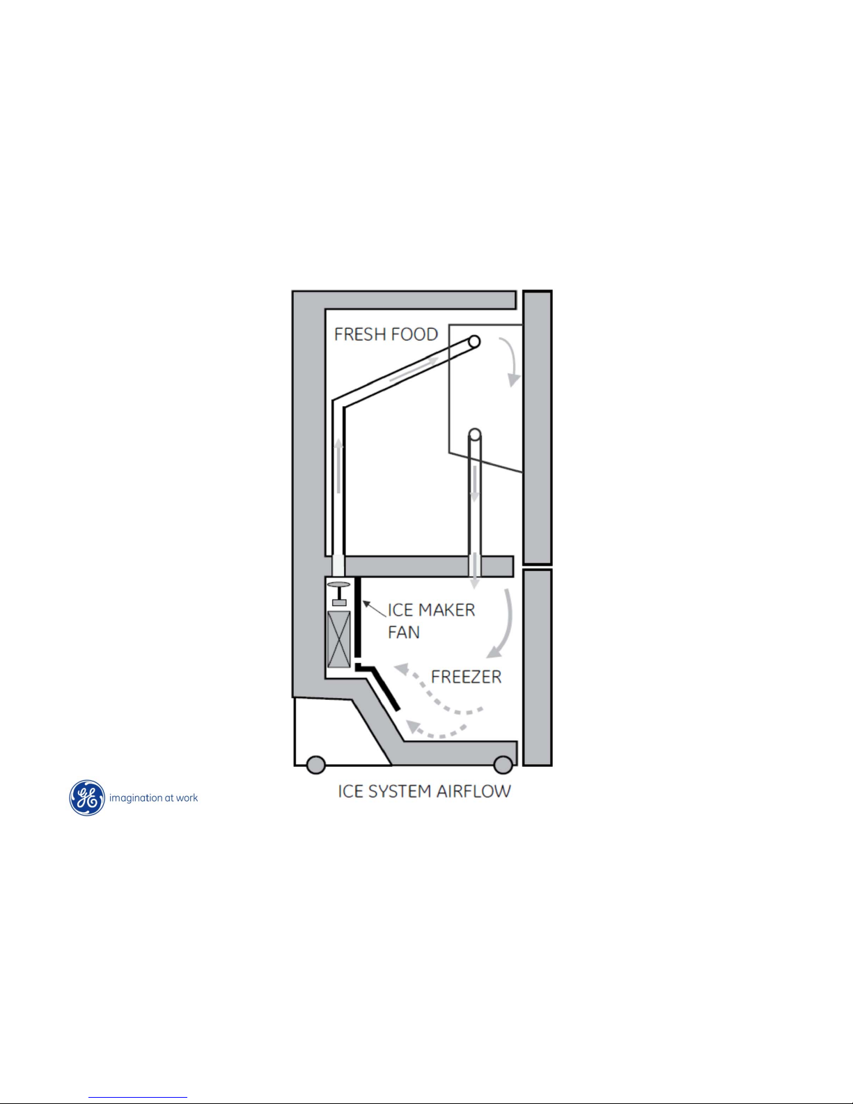
The new BM does utilize a dedicated blower fan to send cold air up from the freezer,
through a channel and into the ice section.
Ice Making/Harvest mode: this mode looks for water valve or dispenser action within a two
hour period of time. ( 4 minute response time) If seen, the ice section temperature should be
approximately 0° F degrees.
Ice Storage mode: if above activity is not detected, the temperature in the ice section could
raises as high as approximately 15° - 25°F.
Ice Hardening mode: this mode tries to account for high number of door openings and maintain
similar temperatures as the ice storage mode
Remember that temperature in the ice section is tied to the control settings so the
warmer the FZ section is set for, the warmer the ice section. A freezer setting below “5”
will produce the warmest ice section temperature.
NOTE: Ice stored for more than 10days could clump.
Page 11
Copyright General Electric 2011
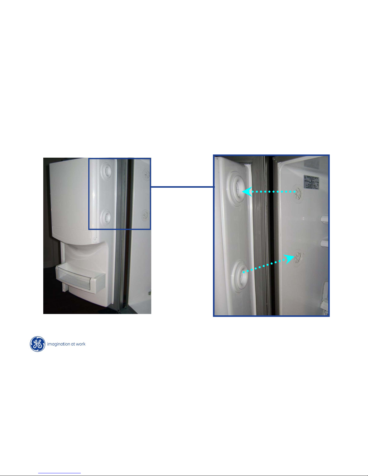
Left Side FF Door Open
• Air enters the new Ice section via duct within the liner
• Air is forced up from the freezer via a dedicated ice door fan and
returns to the freezer via duct.
Page 12
Copyright General Electric 2011
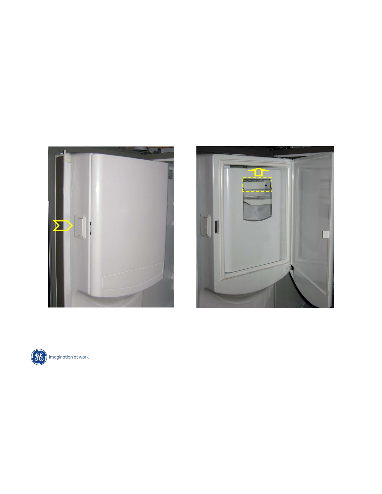
Press in on door latch
Lift up on ice bucket from opening at top
Ice Bucket Removal
Page 13
Copyright General Electric 2011
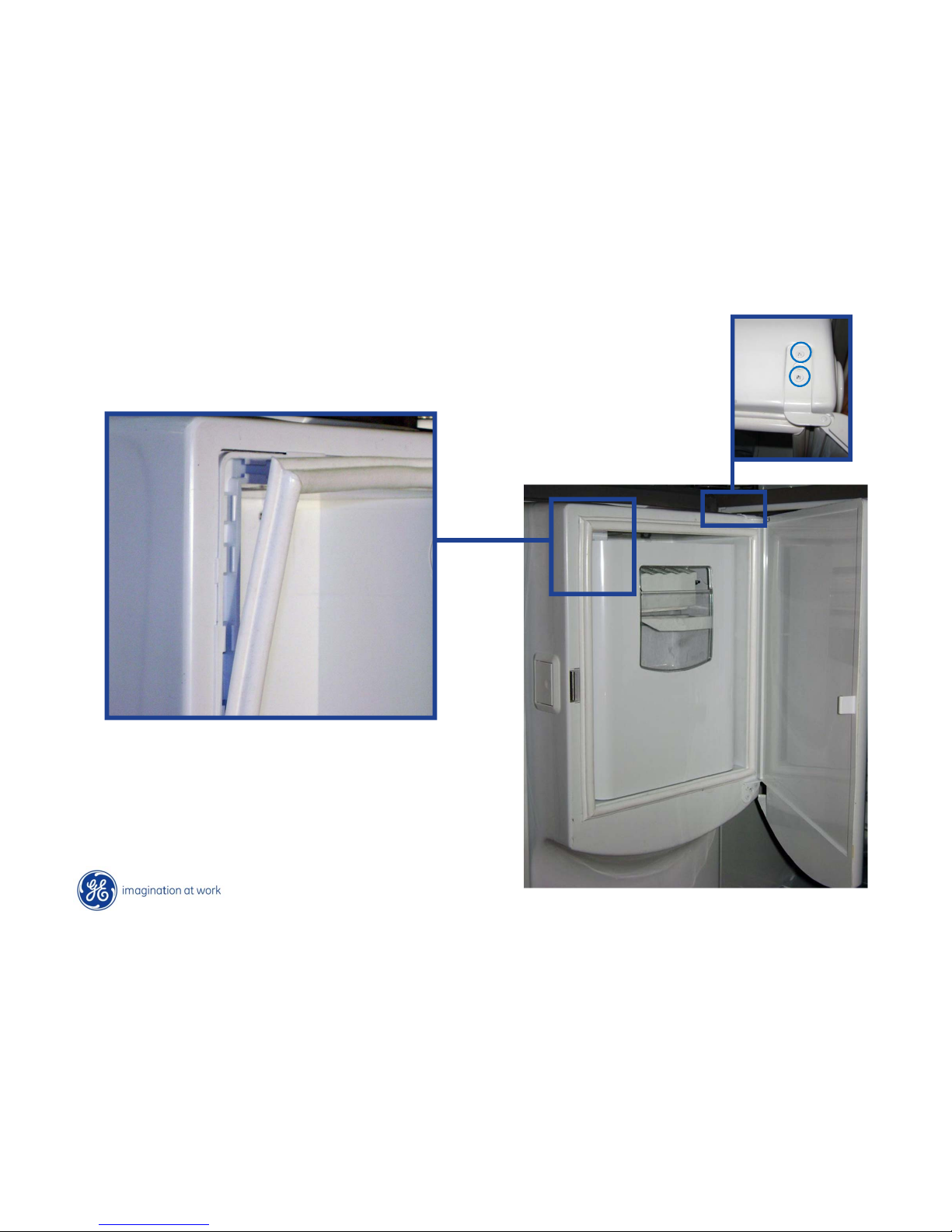
Ice Door Gasket & Hinge
Gasket pulls off and pushes on
Two Phillips-head
screws secure hinge
Page 14
Copyright General Electric 2011
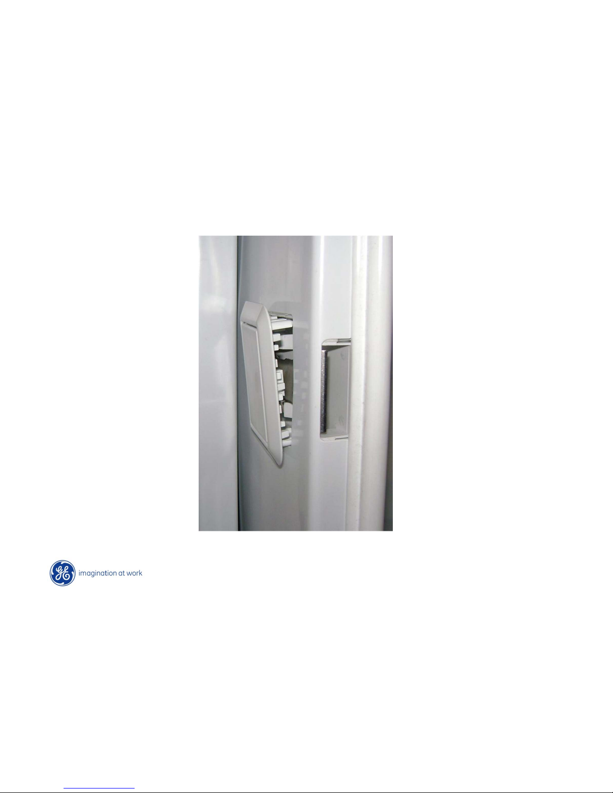
Ice Door Latch
Pry gently around the lip of the cover with a small screwdriver to remove
Page 15
Copyright General Electric 2011
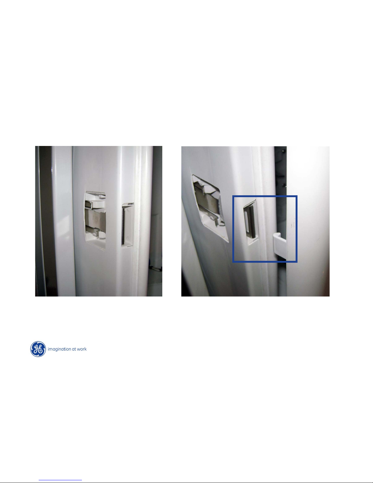
Ice Door Latch
Simple design as metal “catch” bends in and out to secure and release door strike
Page 16
Copyright General Electric 2011
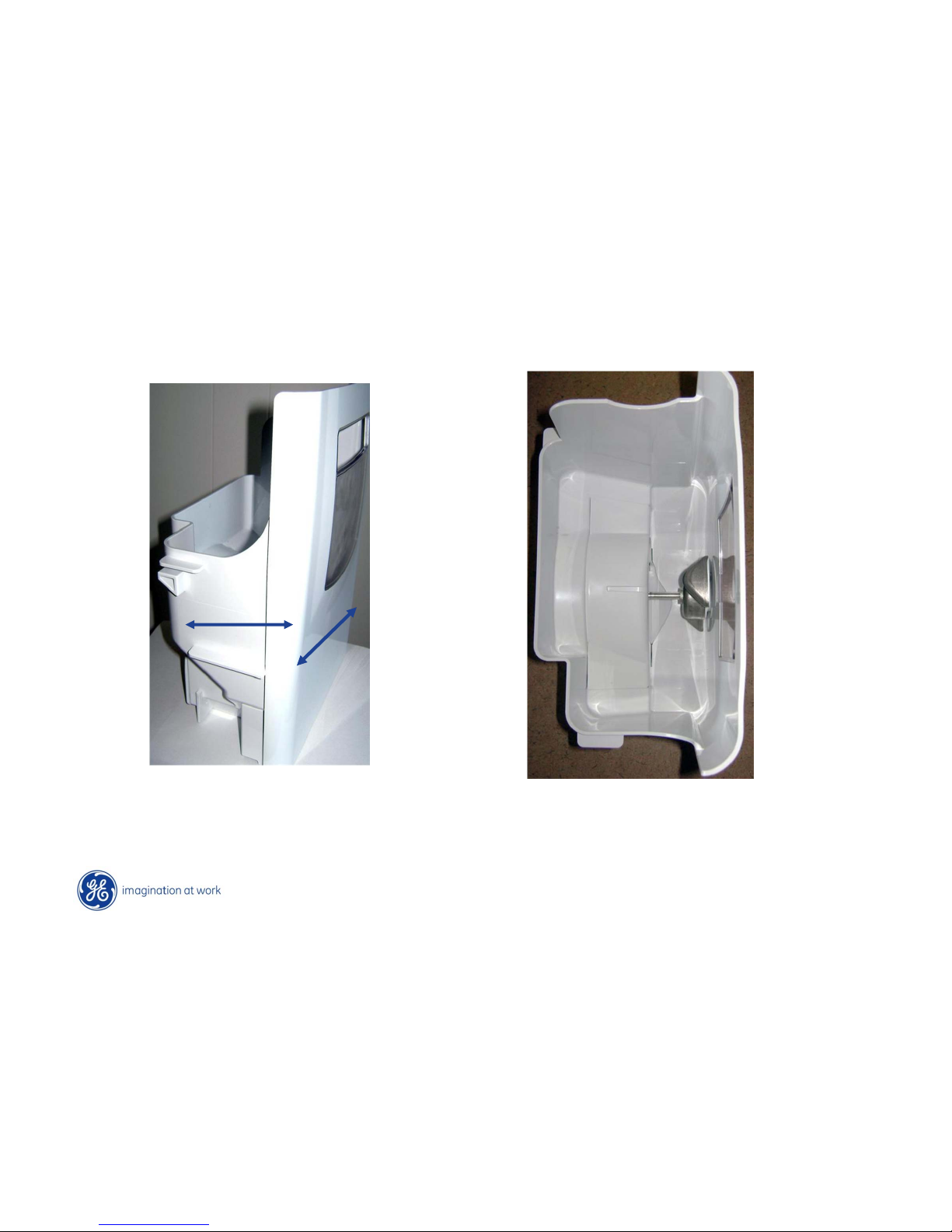
Ice Bucket
Bucket holds
approximately 4 lbs
6”
Bucket appx 6” deep
and 9 ½ wide
9 ½
Page 17
Copyright General Electric 2011
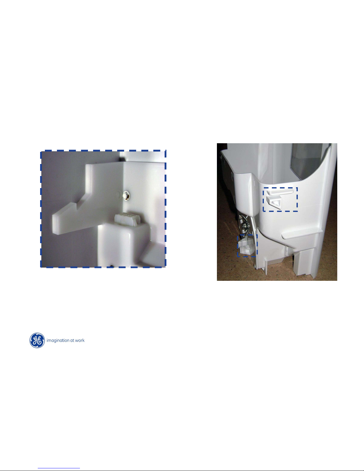
Bucket held in place with guides
(Inside Ice room area)
Ice Bucket
Page 18
Copyright General Electric 2011
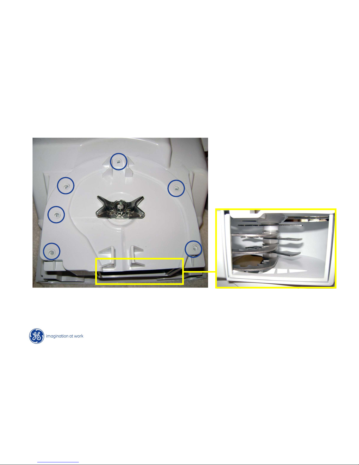
Ice Auger
To access blades:
• Remove 6 Phillips-head screws
• Remove ---- Nut (CCW to loosen - Note locking barbs)
View looking up into blades
Page 19
Copyright General Electric 2011
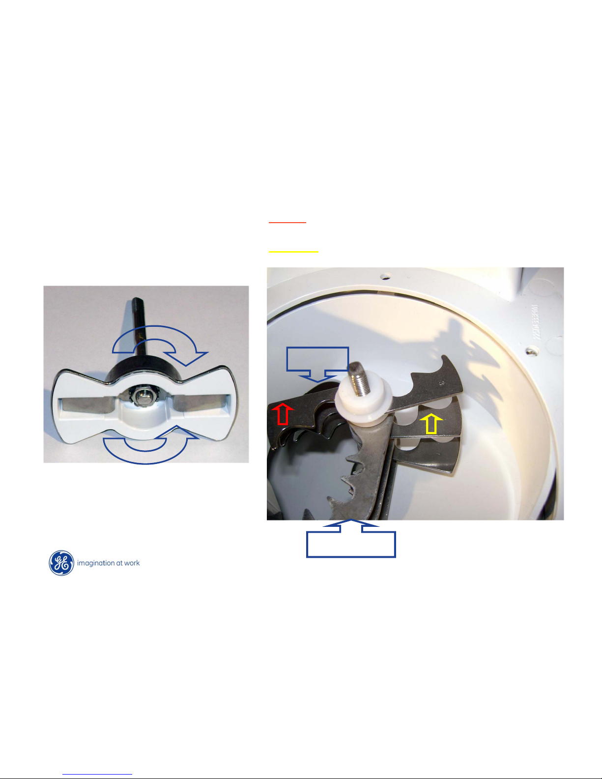
Clockwise - Cubes
Counter-clockwise - Crushed
Crushed
(Facing bucket)
Cubes
Stationary
Cubes: rotation uses back side of rotating blades
Ice avoids going through cutting side.
Crushed: rotates using cutting side and stationary
blades
Ice Auger blades
Ice Enters
Page 20
Copyright General Electric 2011
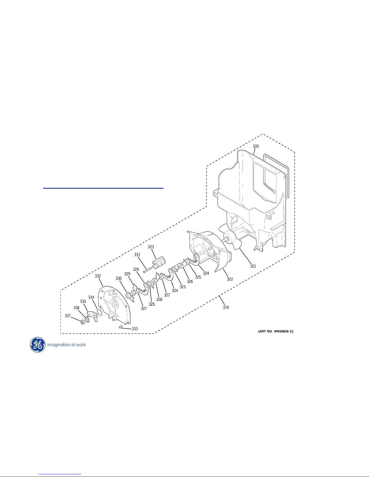
Ice Auger Assembly
Comes as an assembly or in parts
Page 21
Copyright General Electric 2011
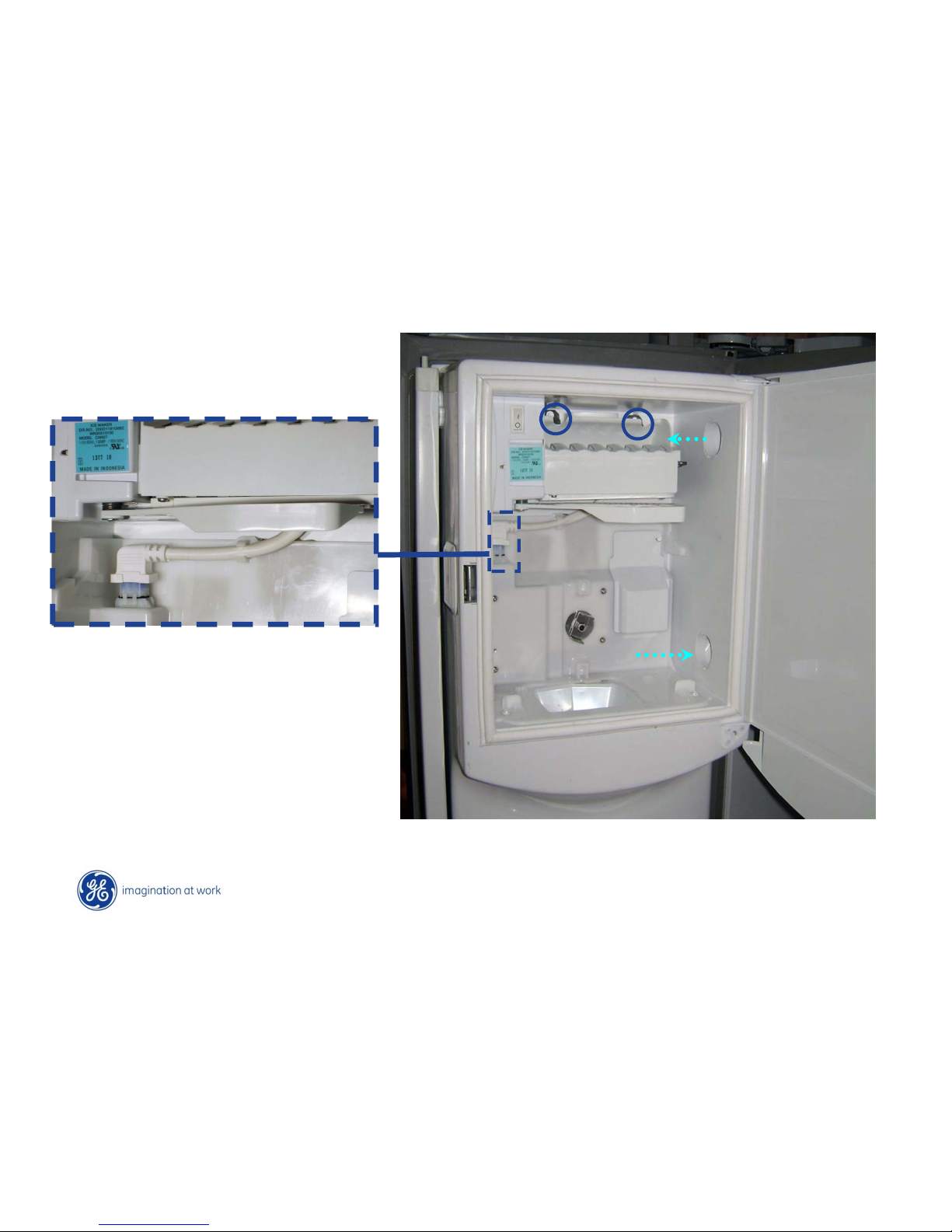
Cold air enters and exits
from side openings.
• Remove IM with two
mounting screws.
• Disconnect IM plug
Ice Maker
Page 22
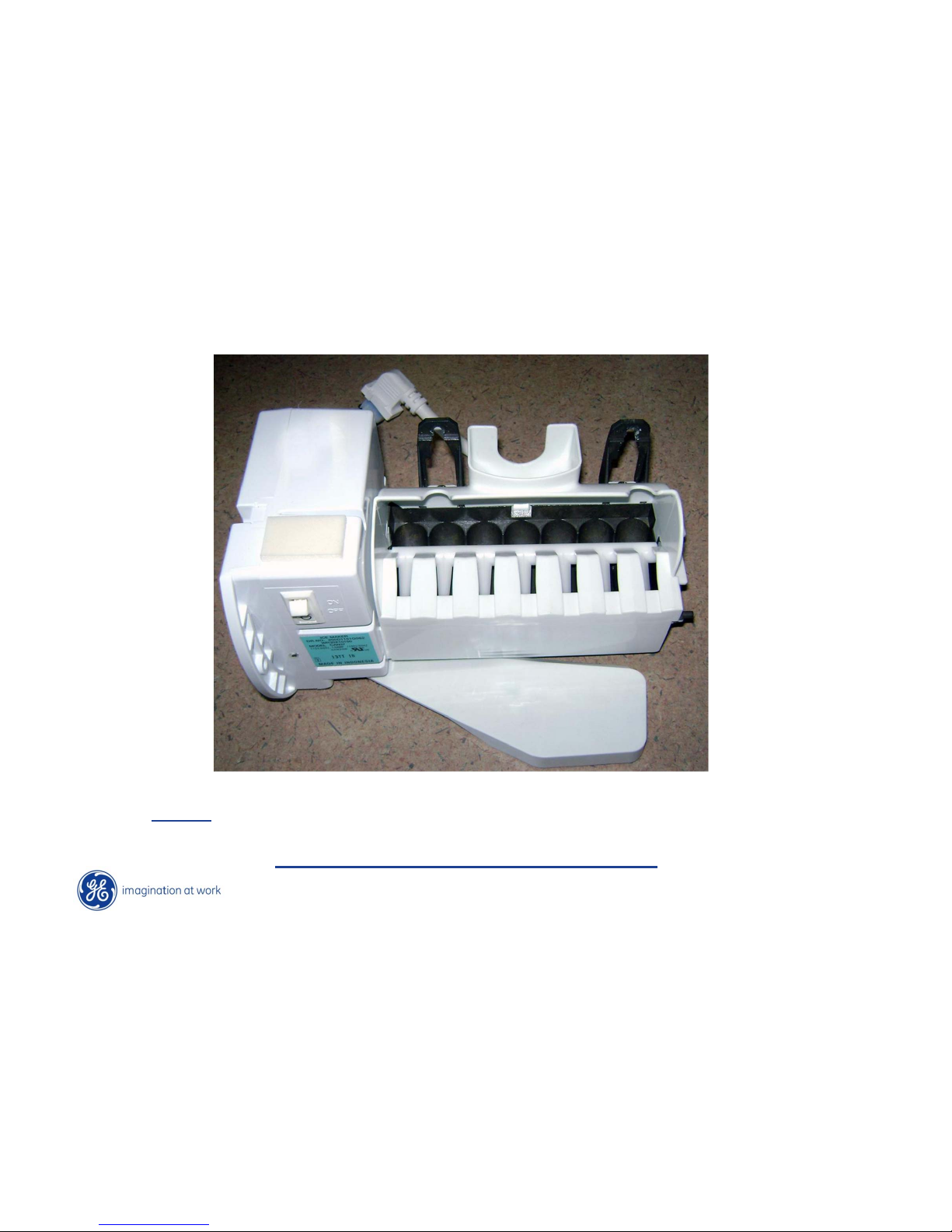
Copyright General Electric 2011
Ice Maker
Curved design fill cup to prevent water splashing with door opening
NOTE: Fill cup comes with IM.
Mechanical IM will not work in this model
WR30X10150
Page 23
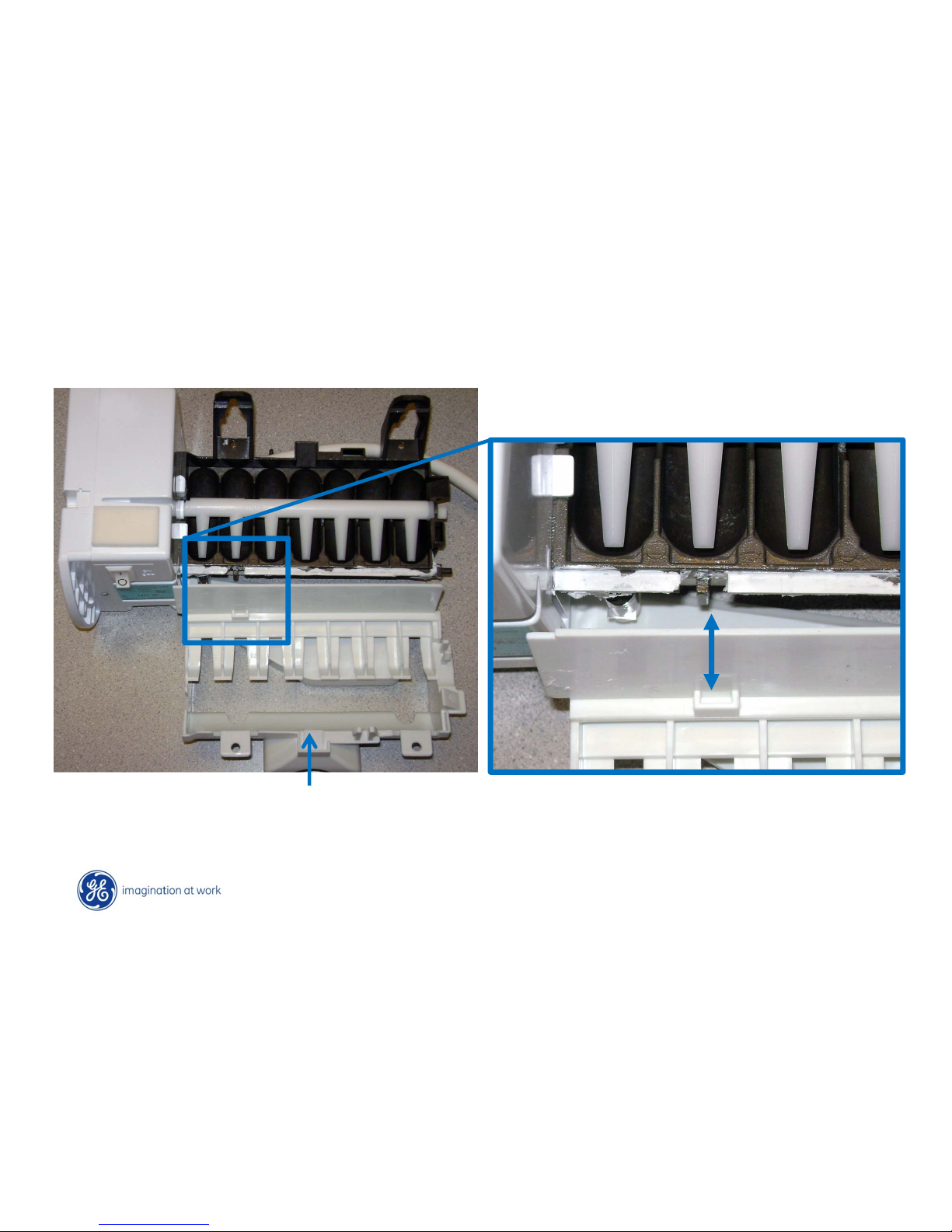
Copyright General Electric 2011
Ice Maker
Note fill cup assembly removed
and upside down for better
viewing.
Electronic IM has different mold than
mechanical. (See notched area)
The fill cup assembly will not mount to
the mechanical IM.
Page 24
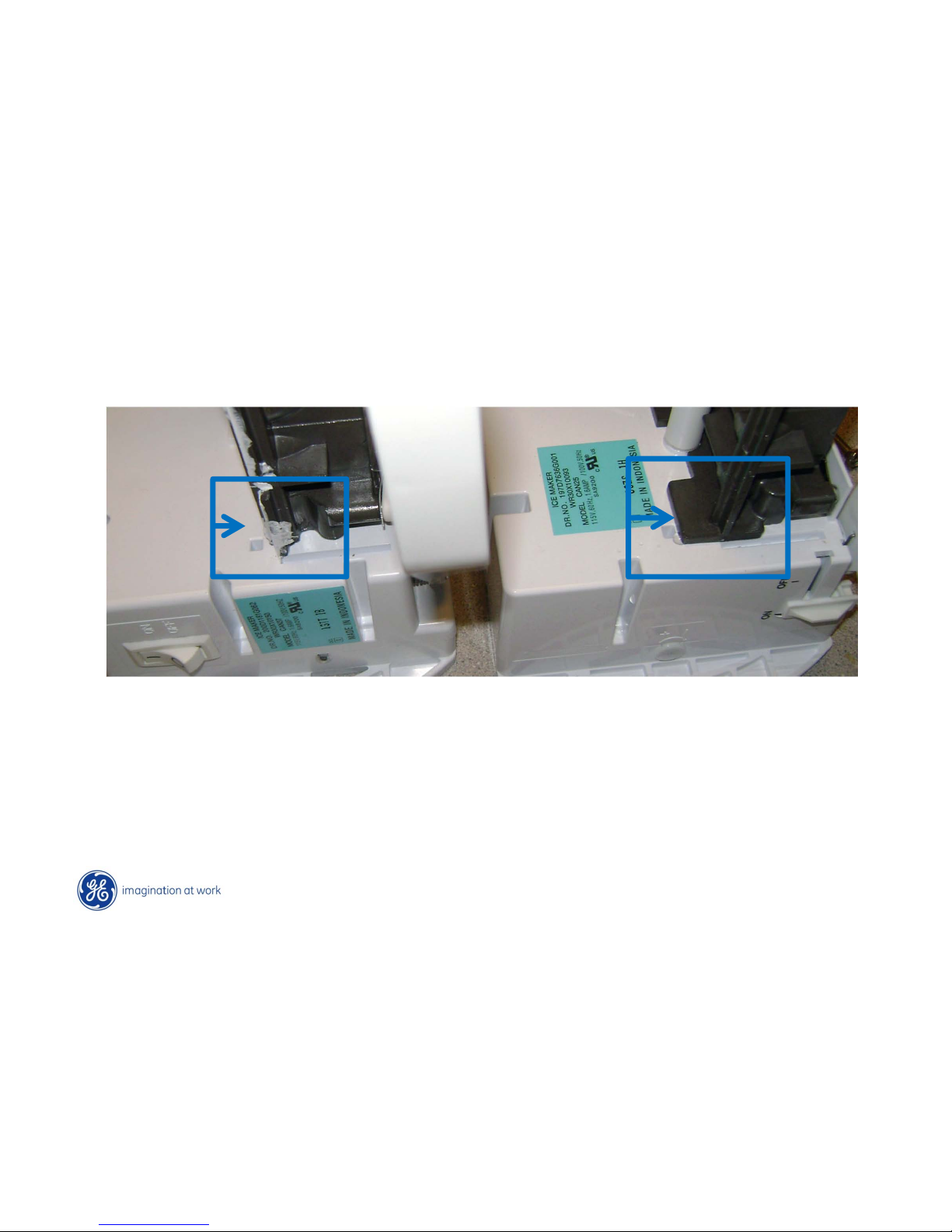
Copyright General Electric 2011
Ice Maker
• Also note the different shapes of the mold body that prevent mounting of the fill cup
assembly that is used on this model. \
• Mechanical I/M does not utilizes a thermistor which is required for this model
• WR30X10150 is sealed to prevent water leaks.
Electronic factory I/M
Mechanical model
Page 25
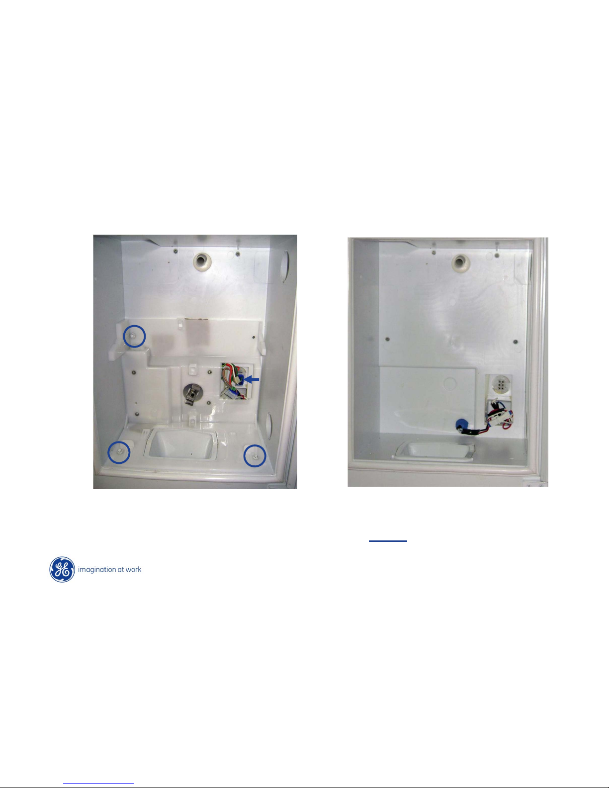
Copyright General Electric 2011
Auger Motor
• Remove wire connector cover
(removed in picture)
• Remove 3 - ¼ white hex head screws
• Disconnect wire harness plug
Auger motor removed
NOTE: Fill tube foamed in door
Page 26
Copyright General Electric 2011
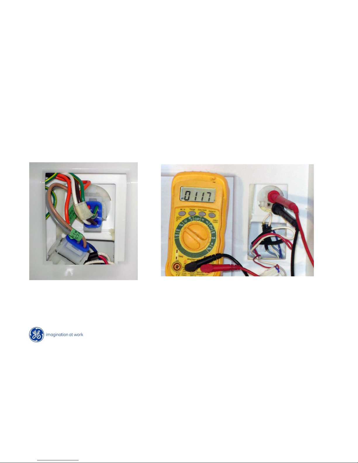
Ice Maker Testing
Orange and Brown wire connectors
Page 27
Copyright General Electric 2011
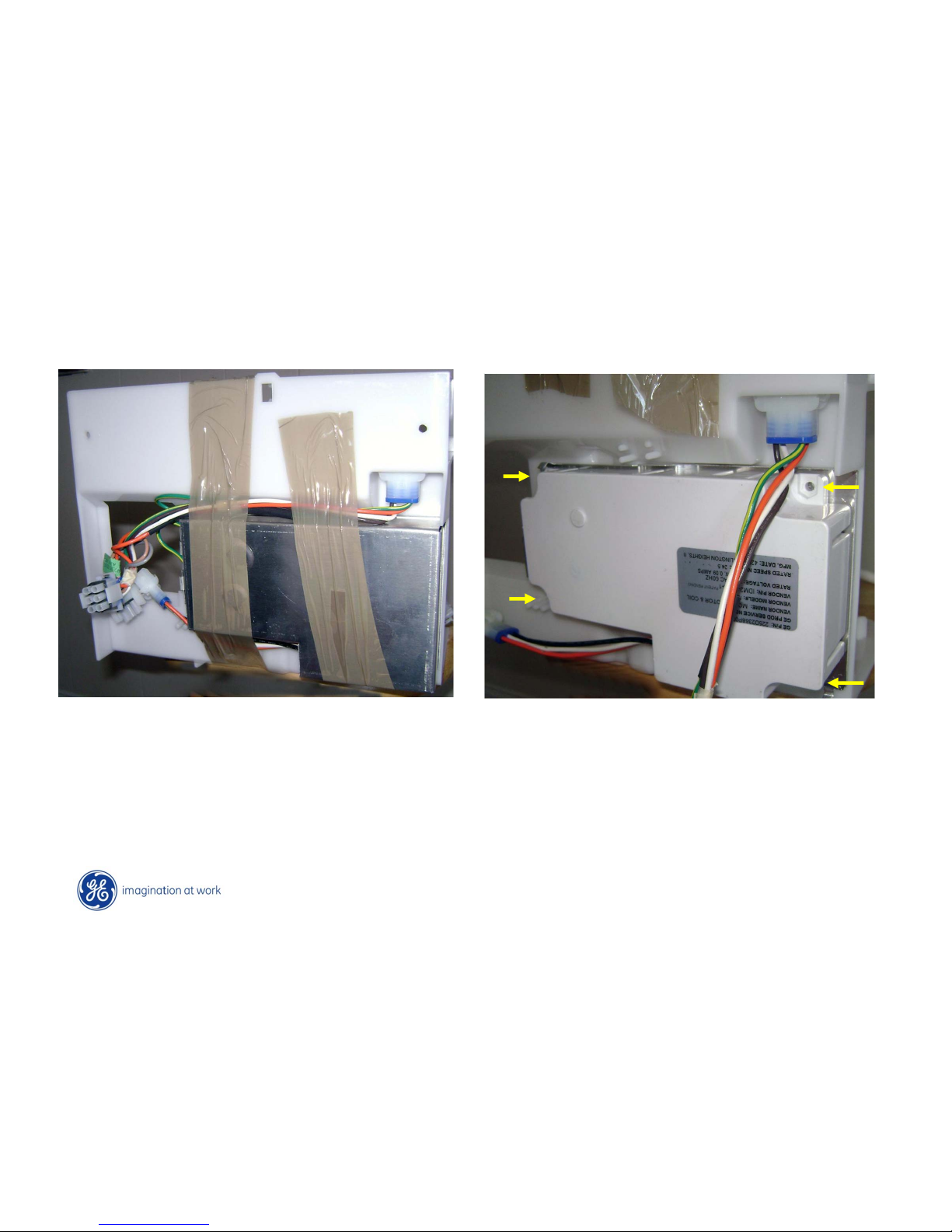
Auger Motor
• Cut tape and remove metal back plate
• Metal plate has tabs that hold it in place
and it just pulls straight off.
Remove 4 mounting screws and nuts
located in the 4 corners.
Page 28
Copyright General Electric 2011
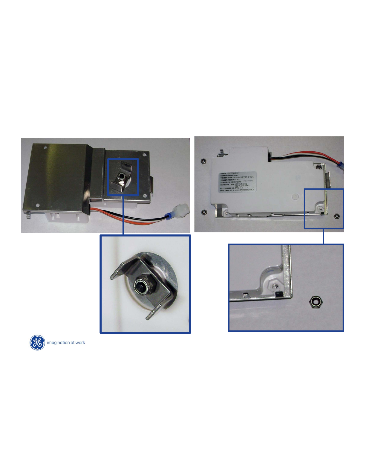
Auger Motor
Remove auger fork by
removing nut
Page 29
Copyright General Electric 2011
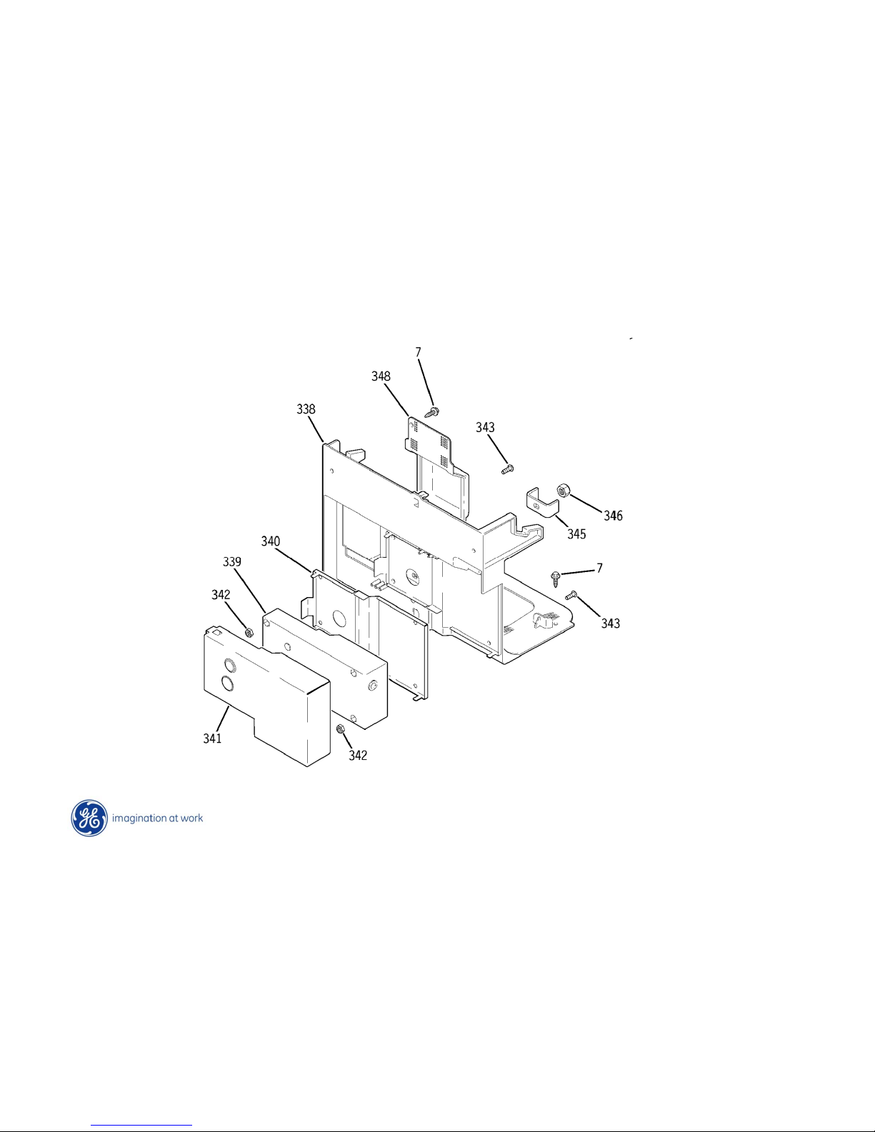
Auger Motor
Components come as shown
Page 30
Copyright General Electric 2011
Auger Motor
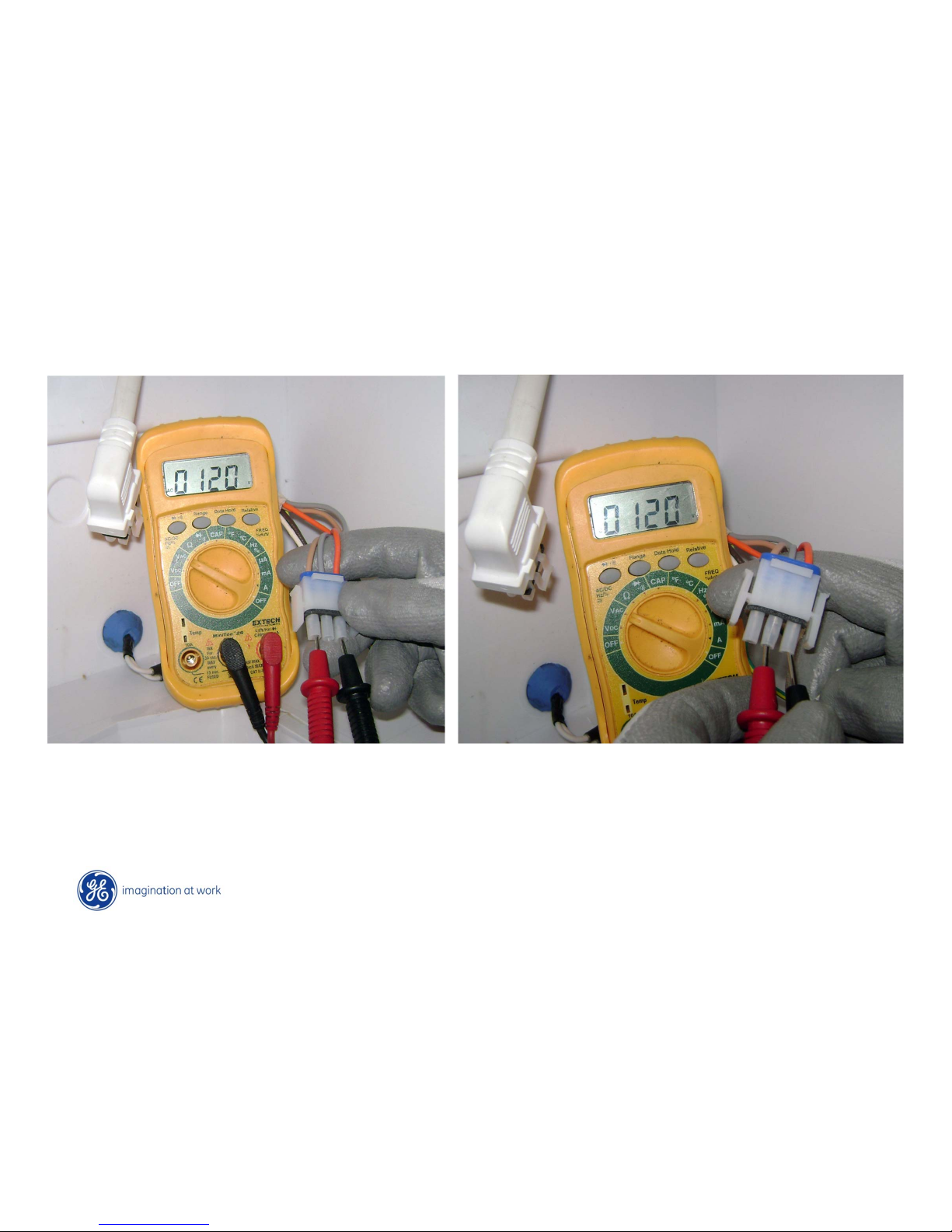
Orange & Silver wire = Cubes
Orange & Beige wire = Crushed
NOTE: Auger motor does a quick “reverse” action when dispensing is stopped (glass
removed) to center the ice bucket cam and unload the crusher (Not noticeable to
consumer) Voltage can be measured at appropriate pins.
Page 31
Copyright General Electric 2011
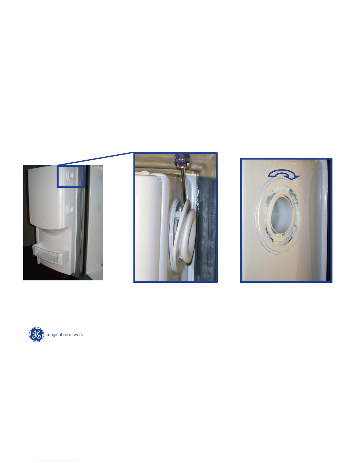
Ice Door Air Vent
Pry gently off
Turn slightly clockwise
and pull straight off.
Page 32
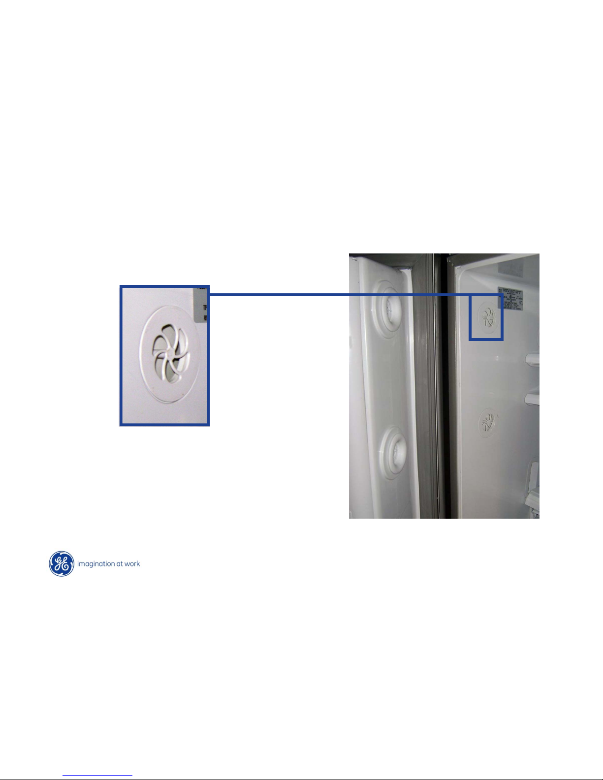
Copyright General Electric 2011
Ice Door Air Vent
Non-replaceable part
(Screw comes in from backside)
Page 33
Copyright General Electric 2011
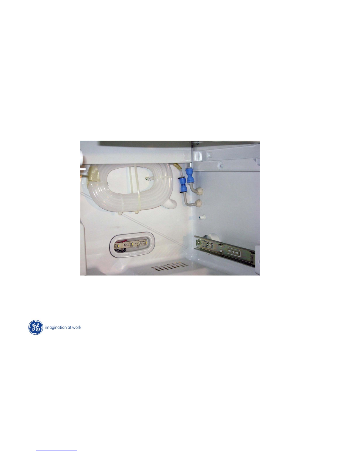
Water Lines
Water line connections on lower right hand corner of FF section
Page 34

Fan Section
Page 35
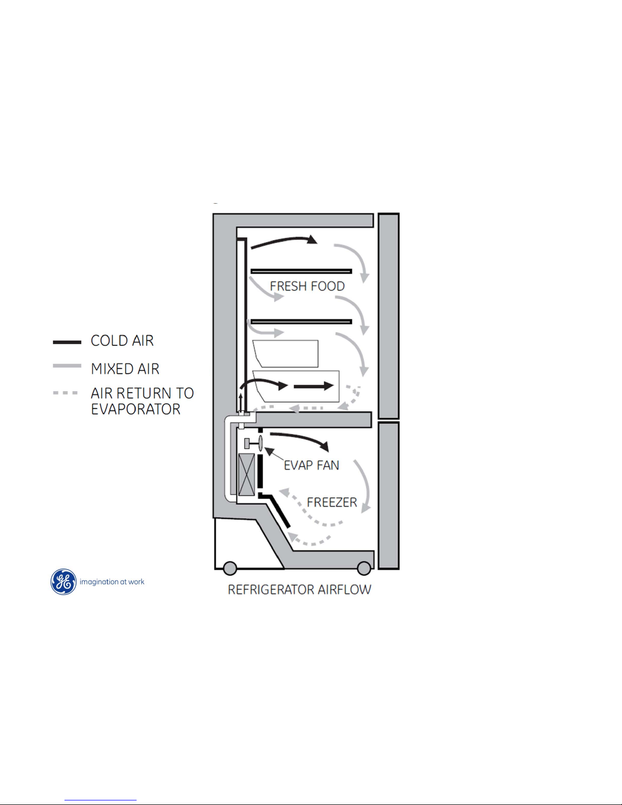
Copyright General Electric 2011
Evaporator Fan
Page 36
Copyright General Electric 2011
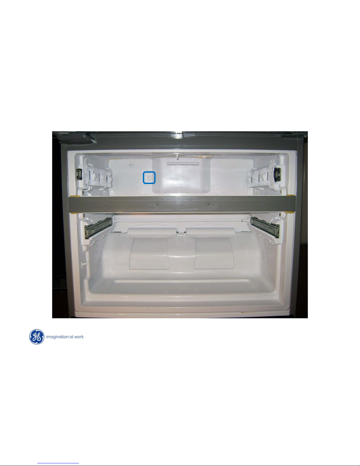
Freezer Evaporator Fan
Remove fan cover screw and swing off
Page 37
Copyright General Electric 2011
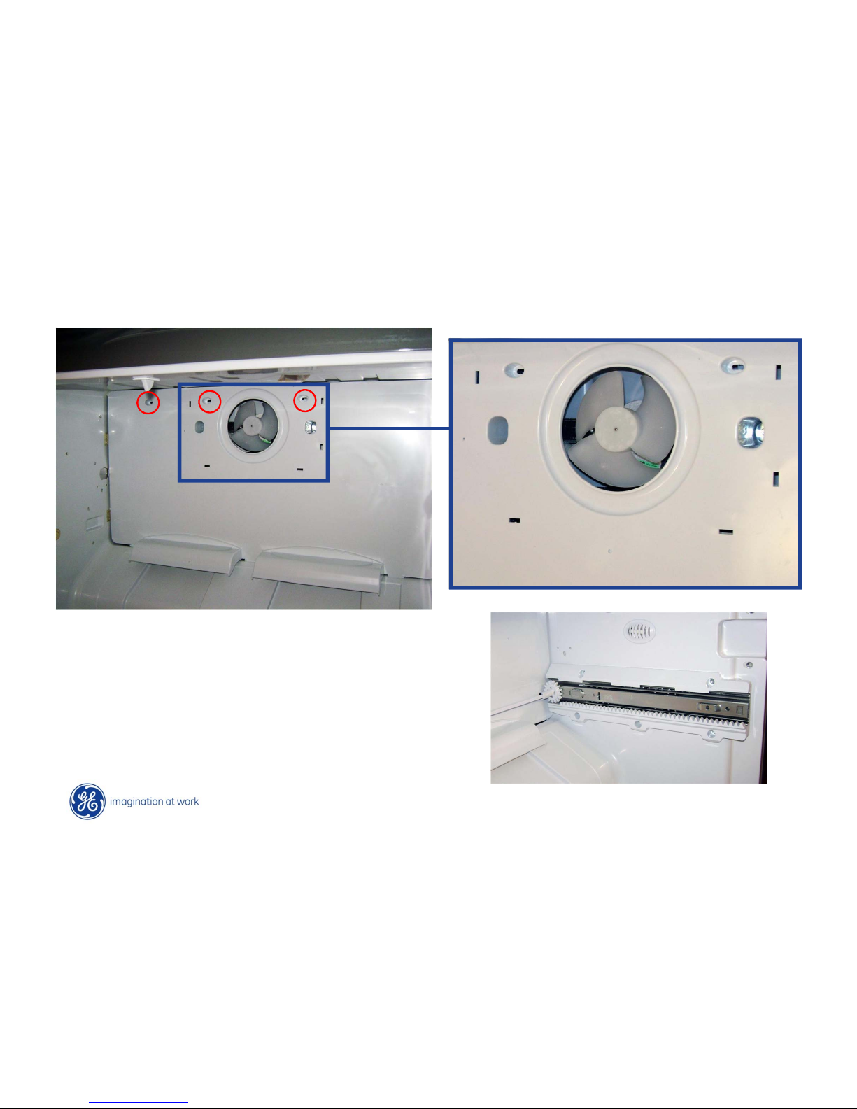
Freezer Evaporator Fan
• Remove side drawer tracks (both sides)
• Remove evaporator cover 3 screws
(More on track removal in drawer section)
Page 38
Copyright General Electric 2011
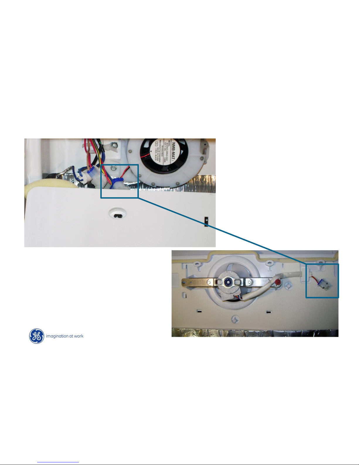
Freezer Evaporator Fan
Tight fit for Evaporator fan plug.
• Remove fan blade. (noting position on
shaft)
• Remove fan mounting bracket two ¼
screws
• 12 VDC. Testing accomplished at plug
or main board.
Page 39
Copyright General Electric 2011
Ice Fan - Duct
Page 40
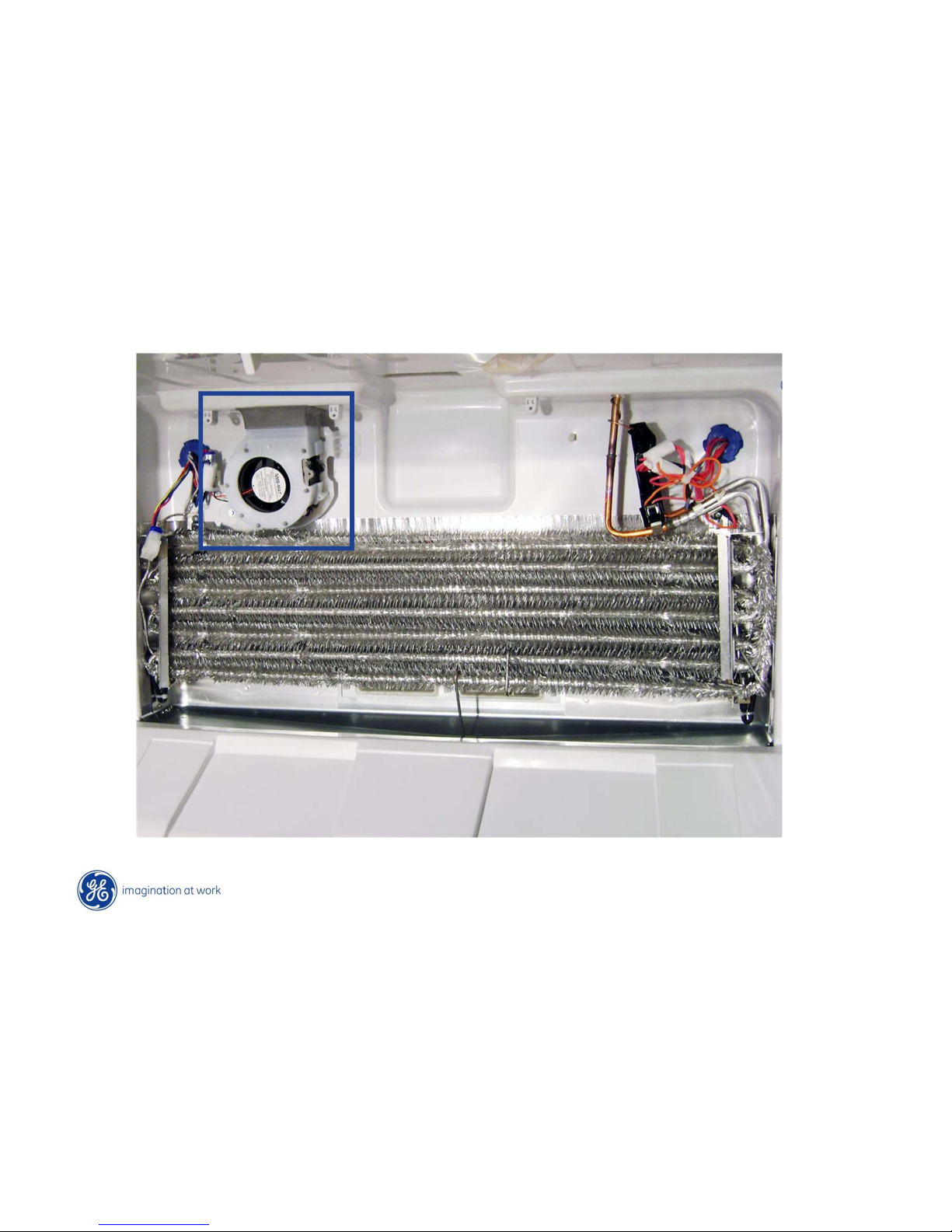
Copyright General Electric 2011
Ice Fan - Duct
12VDC 3 speed fan
Page 41
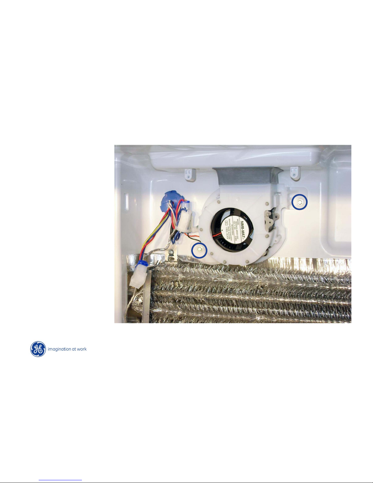
Copyright General Electric 2011
Ice Fan - Duct
• 10 CFM motor
• Ice fan off when
compressor off.
• Ice fan duty cycle’s are
100% or 50% based on
temperature settings.
• Twenty minutes on/off
time during 50% duty
cycle.
• Ice Making mode- fan
on 100%.
Disconnect plug.
Remove two ¼ hex head screws to remove blower
Page 42
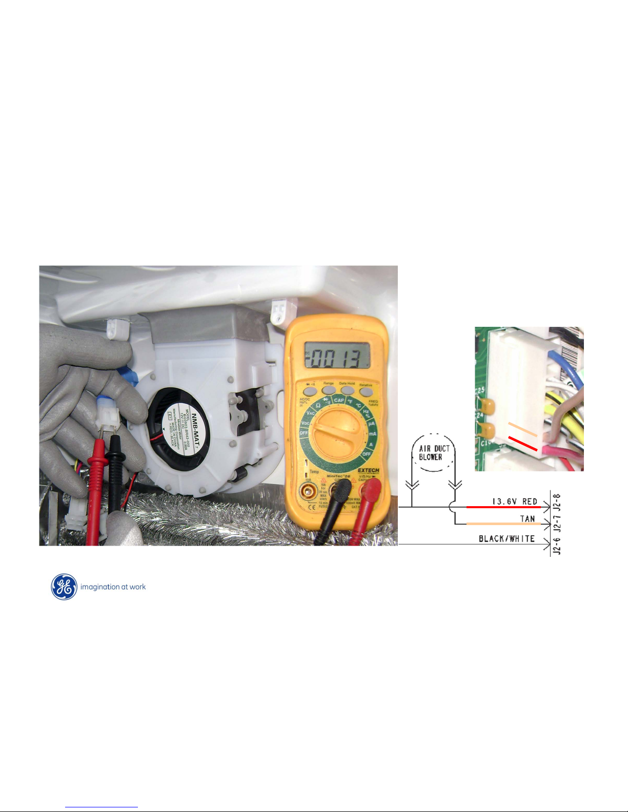
Copyright General Electric 2011
Ice Fan - Testing
J2
Page 43
Copyright General Electric 2011
Ice Fan - Duct
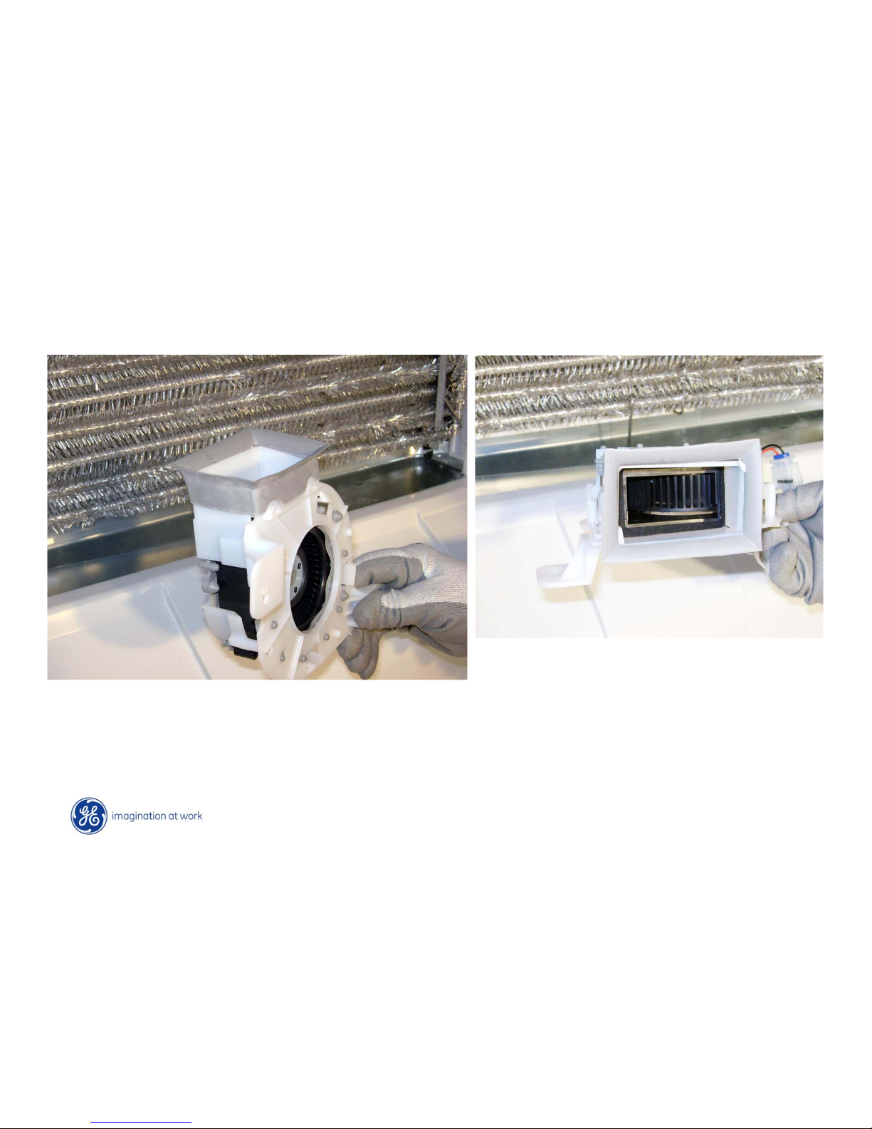
Blower comes as an assembly
Rubber boot separate part.
Page 44
Copyright General Electric 2011
Ice Fan - Duct
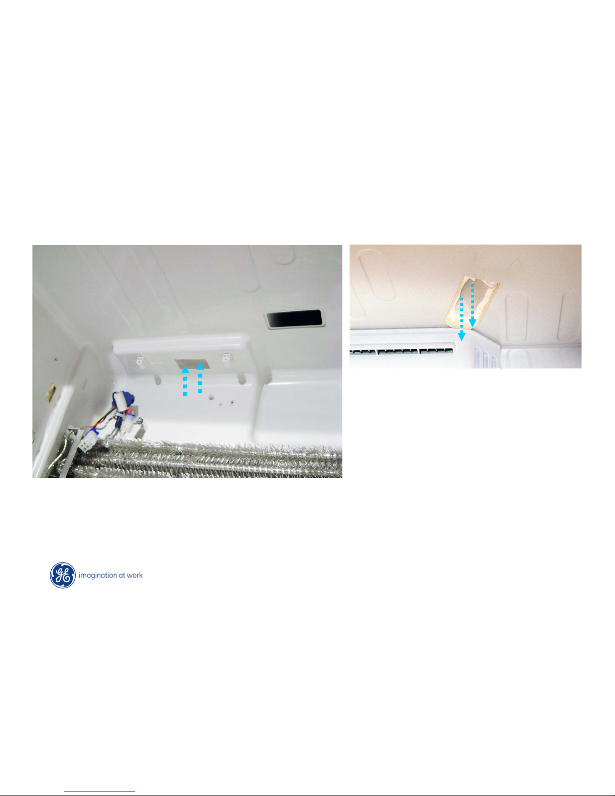
Freezer air travels up through
channel and into ice door section
Returns from ice door back into freezer
Page 45

Copyright General Electric 2011
Abnormal modes:
When the unit is in liner protection mode, the ice box fan will run in low
speed (along with the evaporator fan in low speed)
If the FF damper has been open for 2 hours continuously and the unit is in
ice storage mode, the icebox fan will turn on at low speed and run until the
damper closes
Ice Fan – More Basic Operation
Ice Hardening mode: Fan on high speed, while compressor is on.
Ice Storage mode: Fan on low speed, while compressor is on.
Fan speed and on-time are calculated with a multitude of algorithms.
Changes to the time and speed can vary.
Changing the FZ temp settings will prompt new calculations.
Ice fan off during all phases of defrost. (Defrost, Dwell & Post-dwell)
Page 46
Copyright General Electric 2011
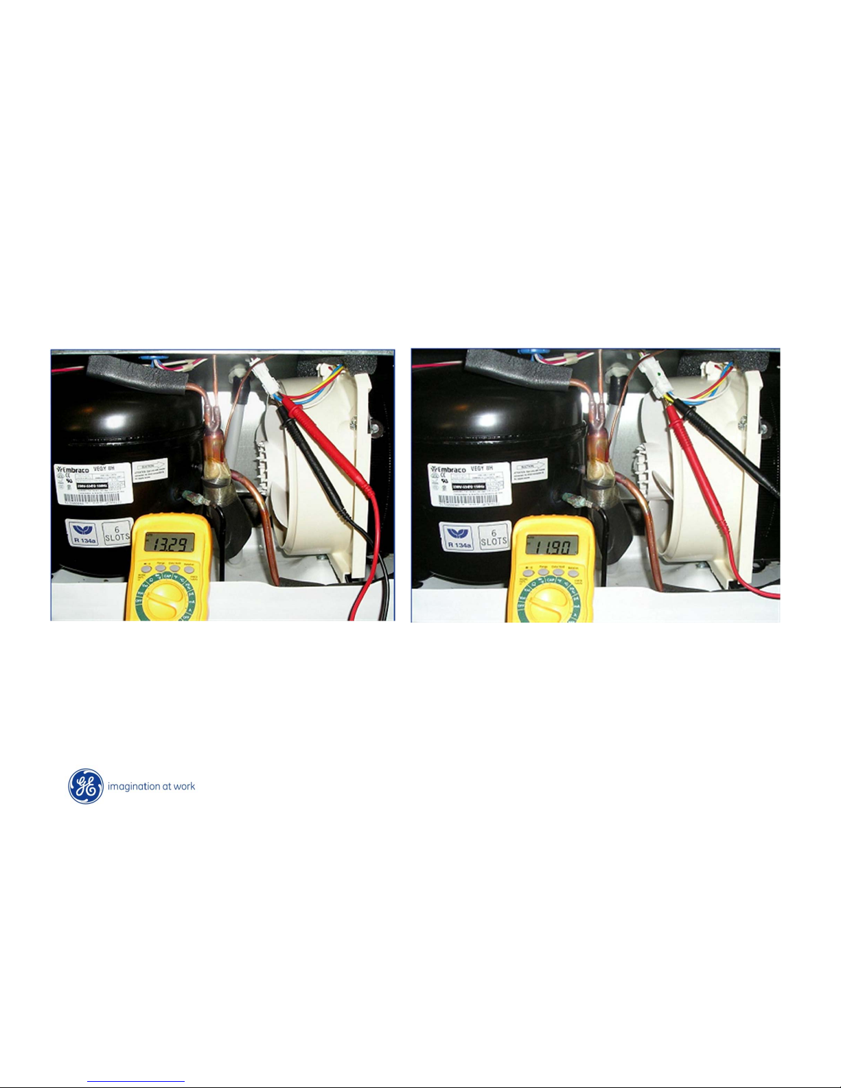
• Measure supply voltage between red & white wires = 13.6VDC.
• Measure signal voltage between yellow & white wires = between 5.5 to
12VDC, depending on the speed of the fan.
Condenser Fan
Page 47
Copyright General Electric 2011
Condenser Fan
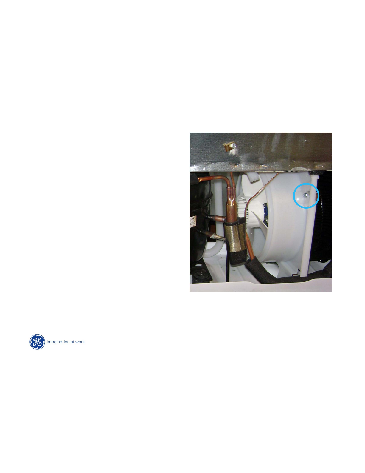
• Remove one ¼” hex head screw
from top of fan shroud.
• Unplug power connector.
• T ilt fan assembly towards
compressor & lift assembly out.
Page 48
Copyright General Electric 2011
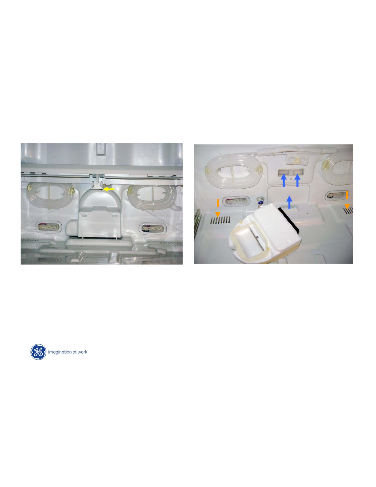
Damper
• Remove one ¼ in screw securing housing to back wall
• Disconnect wiring harness
• 12VDC damper.
• Comes as an assembly
Page 49
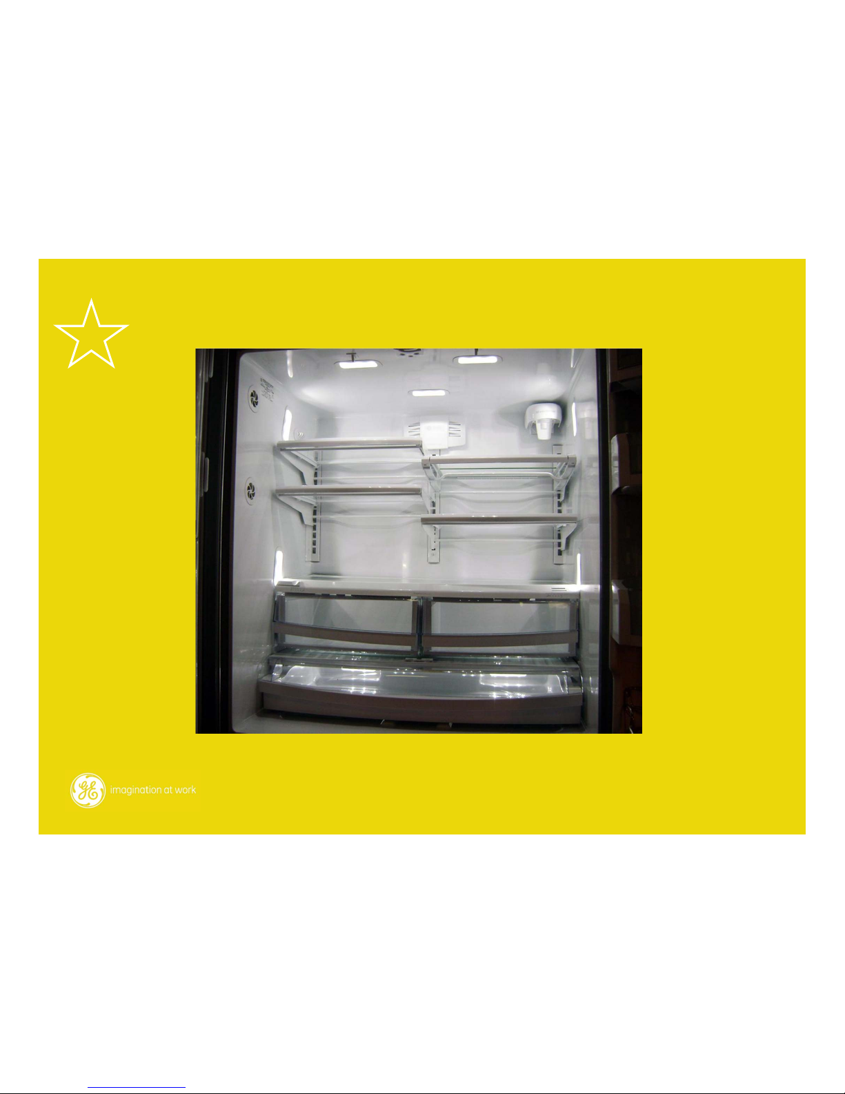
New LED Lighting
Page 50
Copyright General Electric 2011
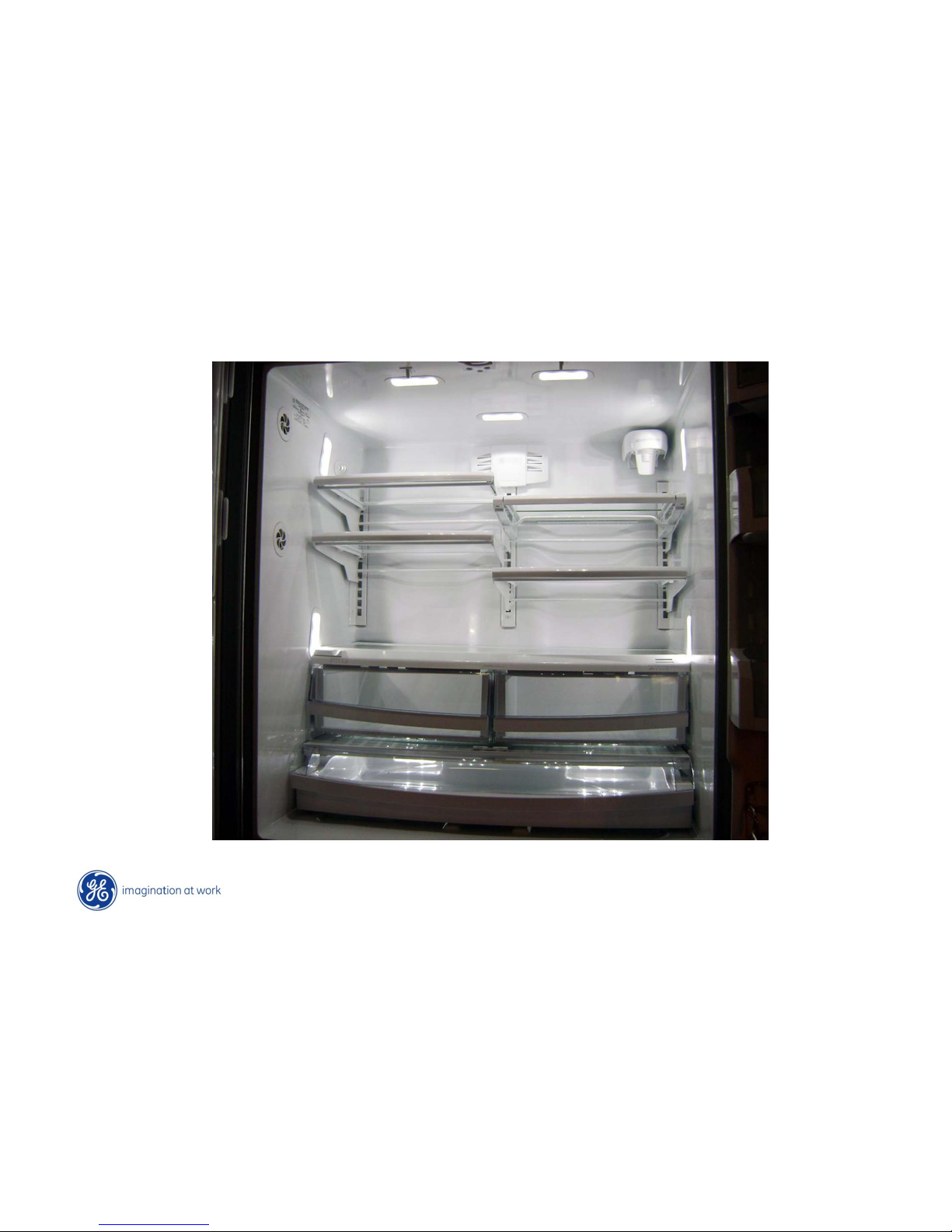
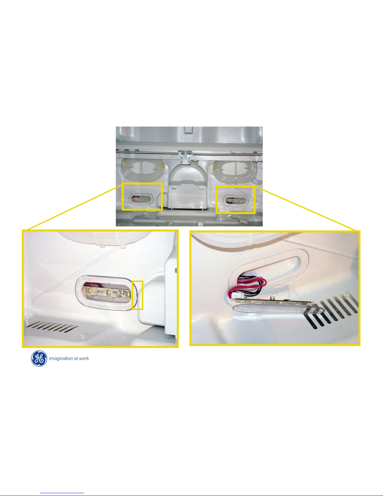
All LED Lighting
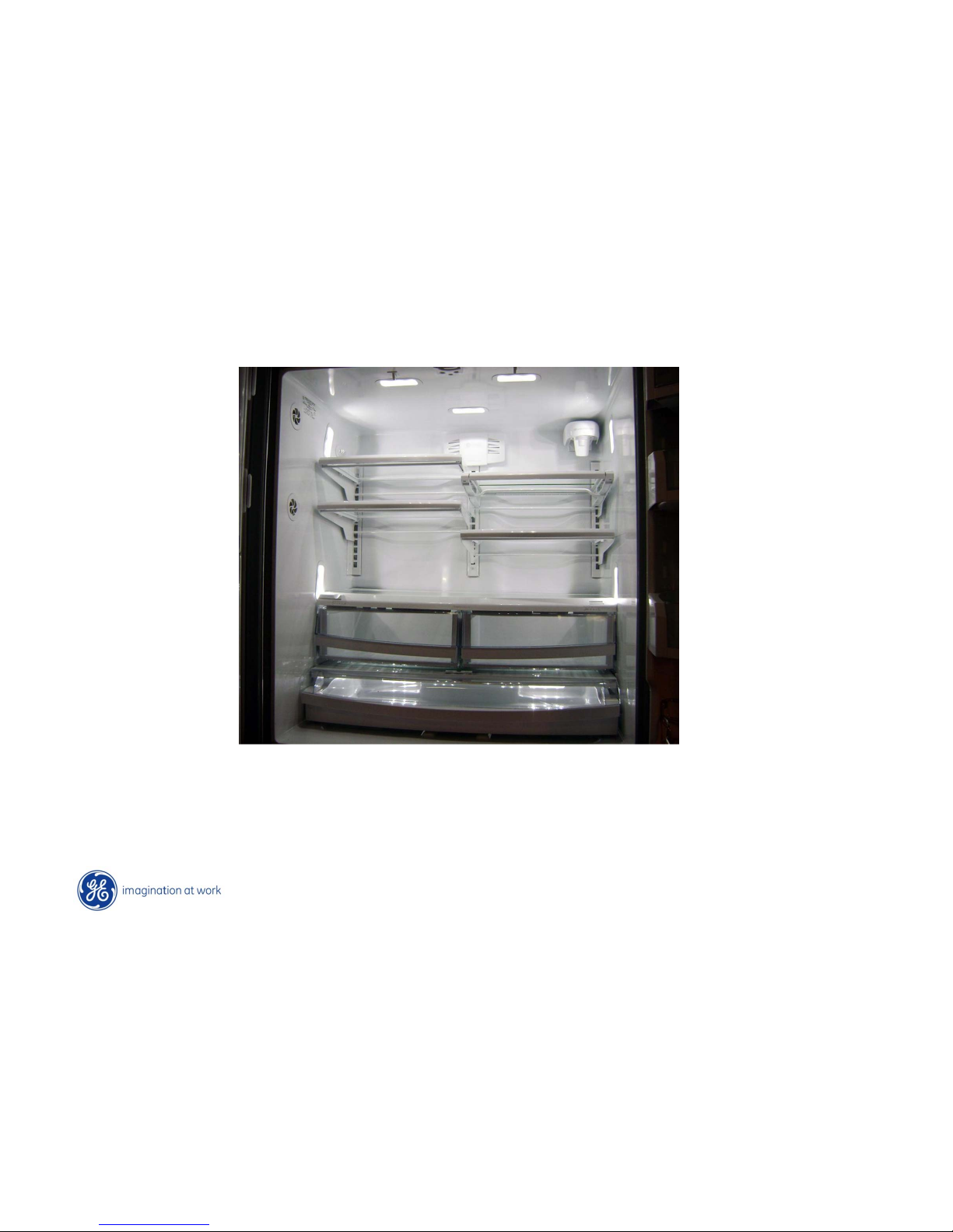
9 LED light pads in FF
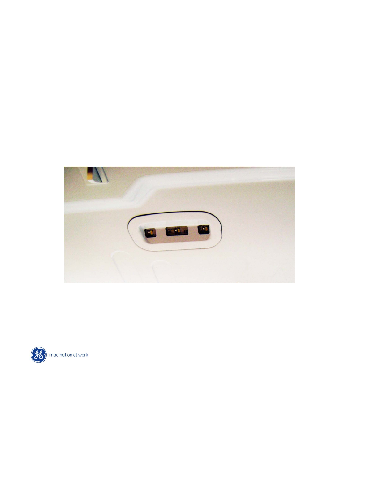
1 LED light pad in FZ
Page 51
Copyright General Electric 2011
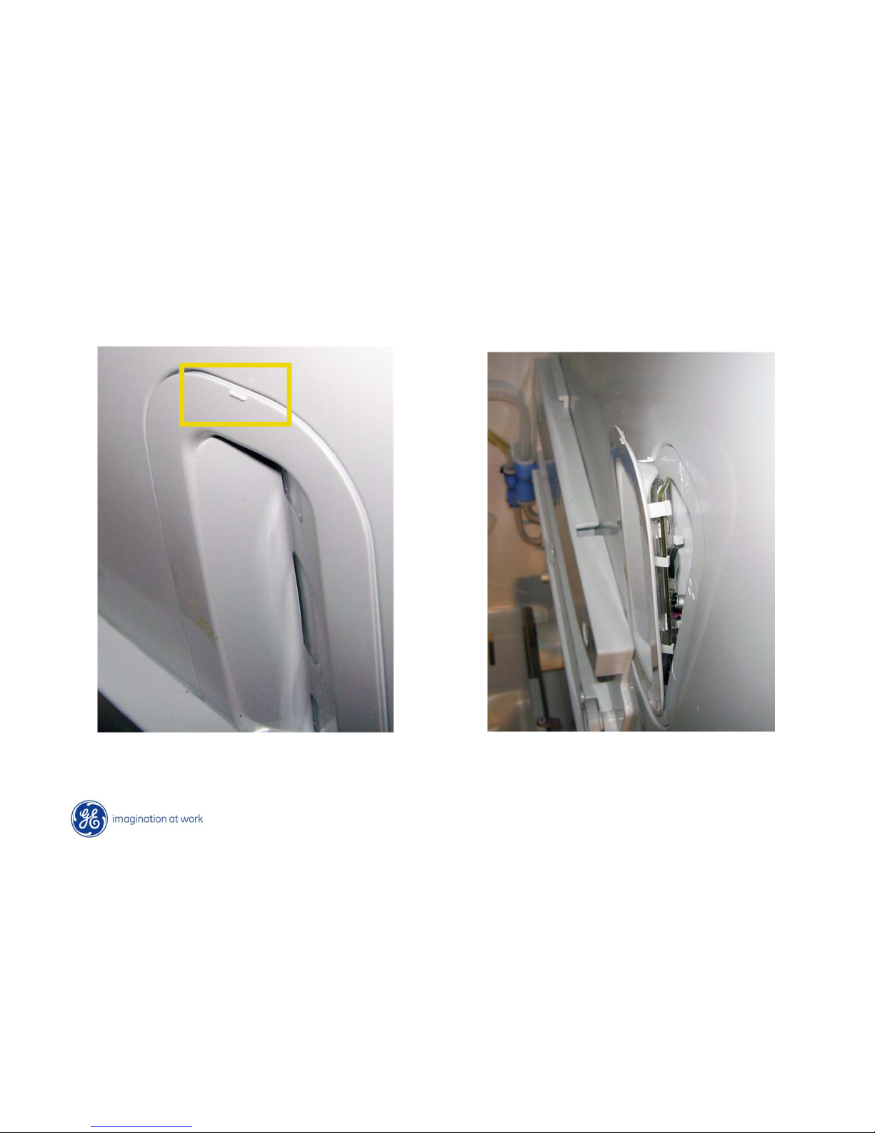
LED Lighting
Gently pry with putty knife or small flat bladed screwdriver at the top “notched” end.
Assembly snaps out and lifts slightly up from the bottom.
Page 52
Copyright General Electric 2011
LED Lighting
Gently pry at notch
Lights in parallel circuit. Bk to Red 13VDC
Bk to Pink 12VDC
Page 53
Copyright General Electric 2011
LED Lighting
Freezer LED is on ceiling in the middle
Page 54
Copyright General Electric 2011
LED Lighting
LED lighting turns off after 10 minutes of door open. Once door closed and
re-opened the 10 minute count starts over. (FF & FRZ)
Page 55
Copyright General Electric 2011
LED Lighting
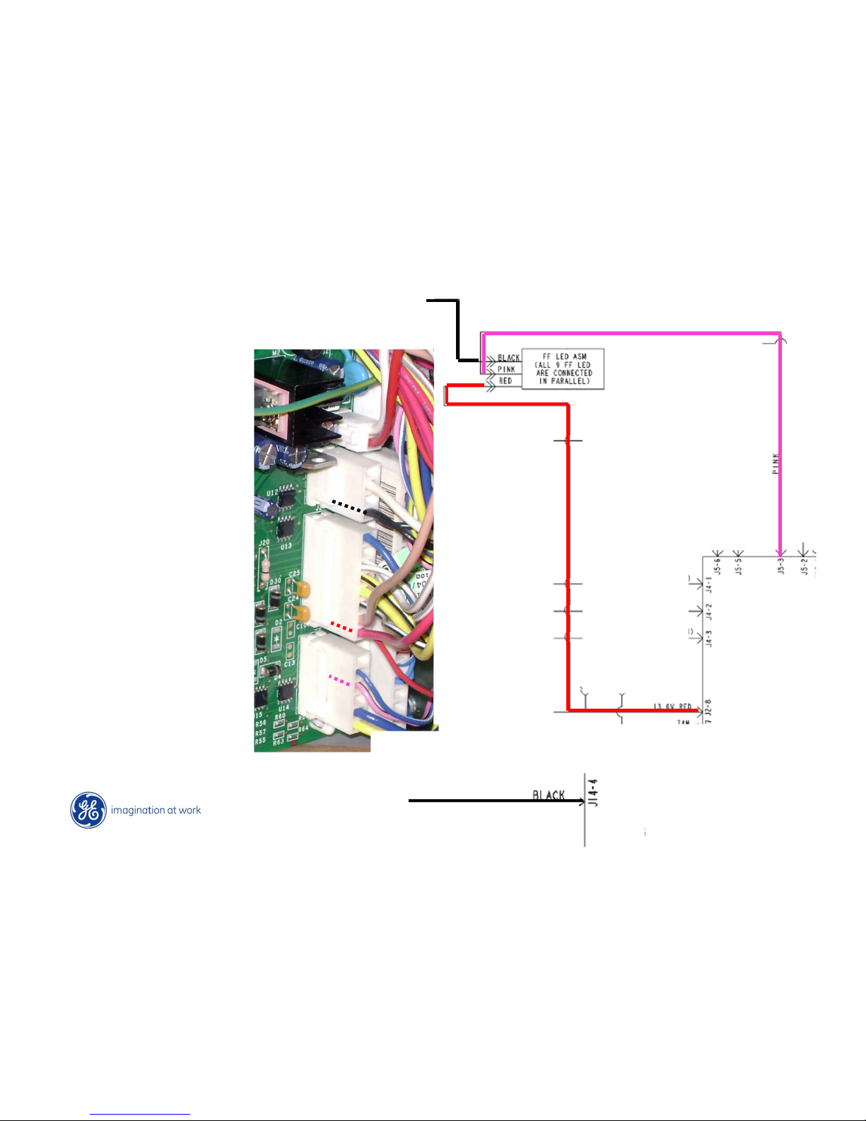
J14
J14 – 4 (BK) LED grnd
J2 – 8 (RED) 13VDC
J5 – 3 (PK) LED enable
J5
NOTE: White wire on
J14 is not going to be
in production as it
was used for Precise
fill feature.
J2
Page 56
Heaters
Page 57
Copyright General Electric 2011
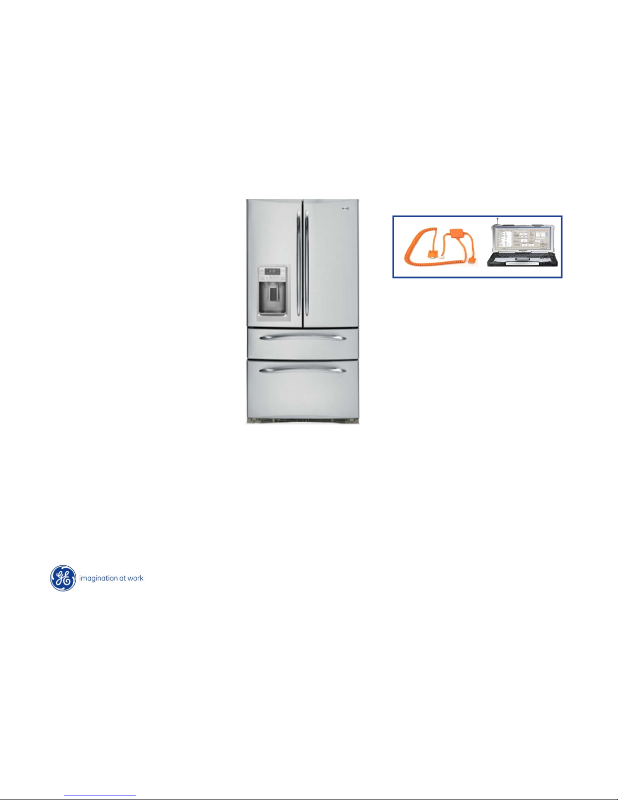
Heater List
A/C heaters
D/C heaters
Return Duct heater LH 440 Ω
Return Duct heater RH 440 Ω
Air Duct heater 578 Ω
Supply Duct heater 1653 Ω
Duct Port heater 1200 Ω
* Defrost heater 31 Ω
* Double Drawer (DD) Mullion heater 827 Ω
Horizontal Mullion between FF & FZ 1653 Ω
**Door Gasket heater 62 Ω
**Recess heater 145 Ω
* Duct Door heater 109 Ω
* French Door Vertical Mullion 24 Ω
**Fill tube heater 300 Ω
No asterisk indicates non replaceable
* Replaced as individual heater
** Replaced as door assembly
NOTE: New Version being tested
to incorporate new heaters
Page 58

Copyright General Electric 2011
Heater Basic Operation
Duct Port heater - cycles based on temperatures and ice box condition. (Ex: mid –mid settings
appx 30% on time.) Located around the holes for ice door.
Supply Duct heater - come on with abnormally high door opening time and high room humidity
Air Duct heater (abnormal is appx. 70 FF openings for 12 sec. or more in 16 hours)
Door Gasket heater - are on all of the time with a FZ setting of 4 or lower. Above that varies.
Recess
Duct door
Fill Tube heater - on for 2 hours after water valve activation or when ice is dispensed.
Page 59
Copyright General Electric 2011
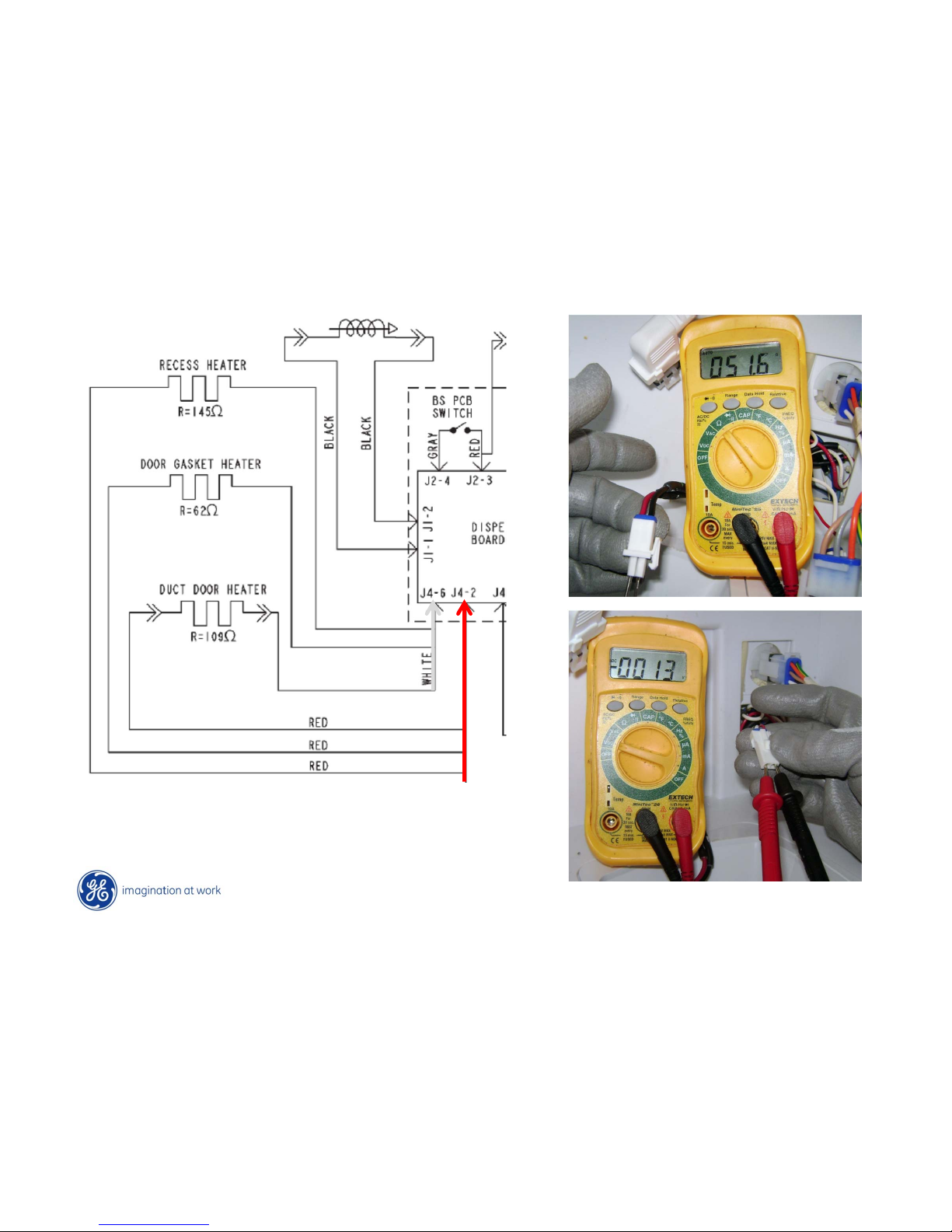
Heater Test
Heaters operate based on temperature settings
i.e. FRZ setting of 5 or higher = 100% “On” time
except during ice dispense. (Circuit can be tested at
dispenser board also. Wh/Red)
Page 60
Copyright General Electric 2011
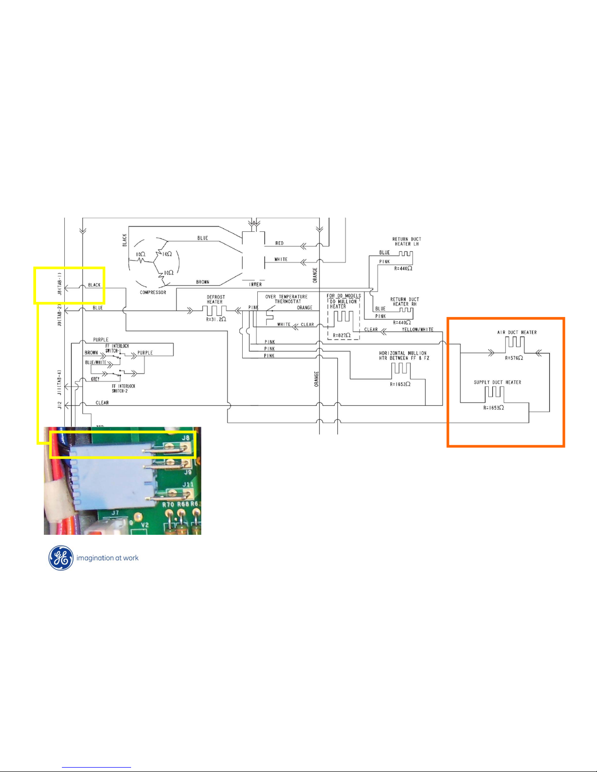
Air Duct & Supply Heaters
Air Duct and Supply Duct heaters use J8
(compressor) relay
NOTE: This model is inverter controlled so J8
is not used for compressor.
Page 61
Copyright General Electric 2011
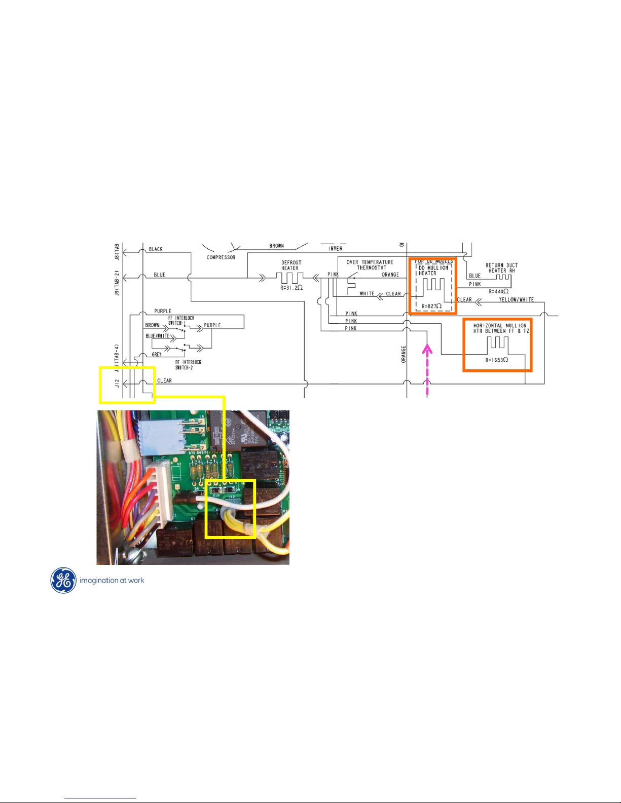
Double Drawer & Horizontal Mullion Heaters
Off during ice dispense to reduce power
supply output and remain off for 5 more
seconds after ice dispense completed.
(Port Heater)
Page 62
Copyright General Electric 2011
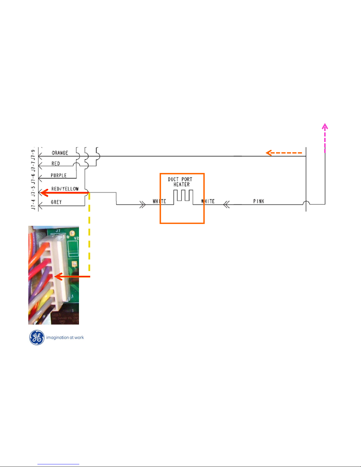
Port Duct Heater
Port heater cycles based on temperatures and ice box
condition. (Ex: mid –mid settings appx 30% on time.)
Test from J7 – 9 (Orange neutral) to J7 – 5 (Red/Ylw)
R = 1200 Ω
Page 63
Copyright General Electric 2011
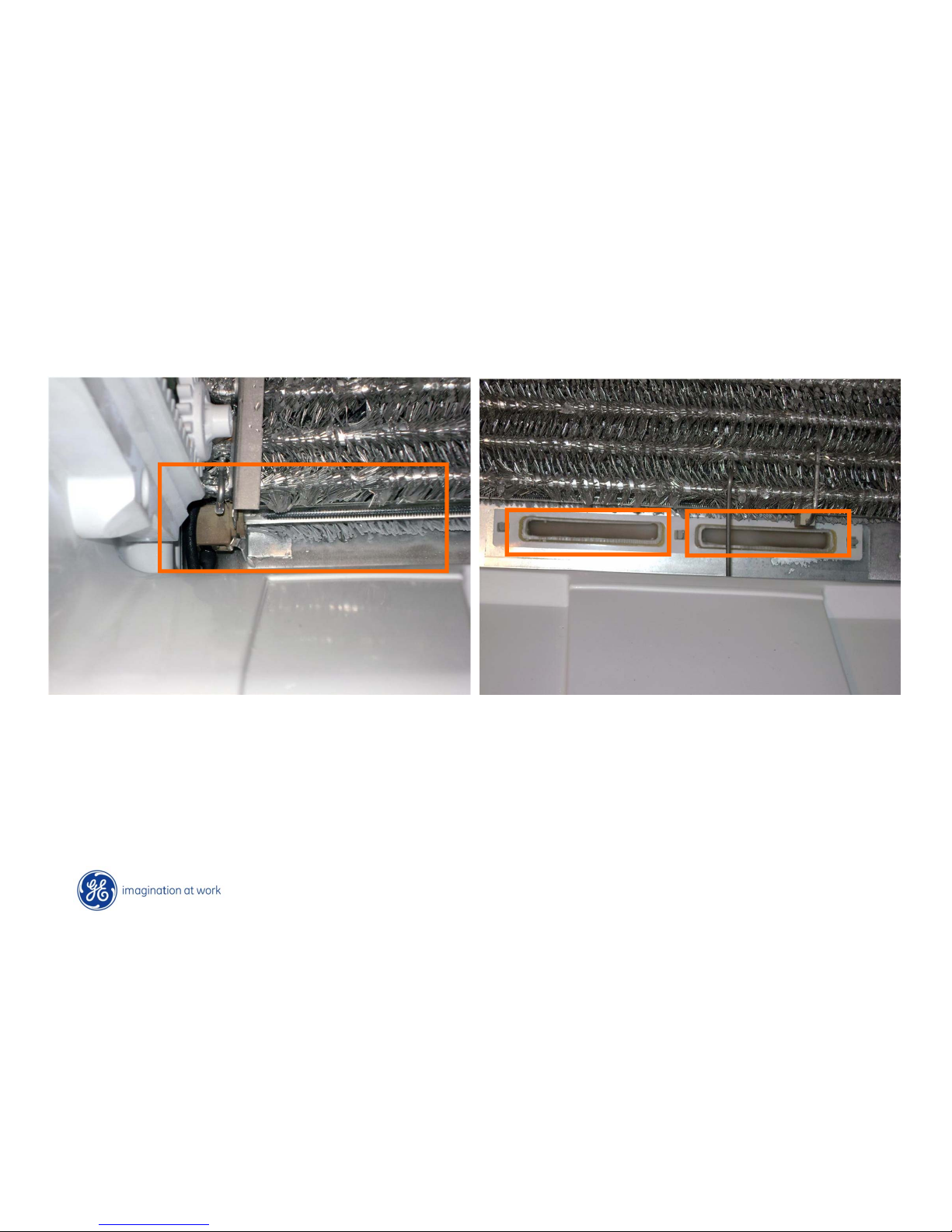
Defrost Heater – Return Duct Heaters LH & RH
440 Ω Return duct heaters. Not replaceable31 Ω Defrost heater
Heaters are in a parallel circuit and on at the same time
Page 64
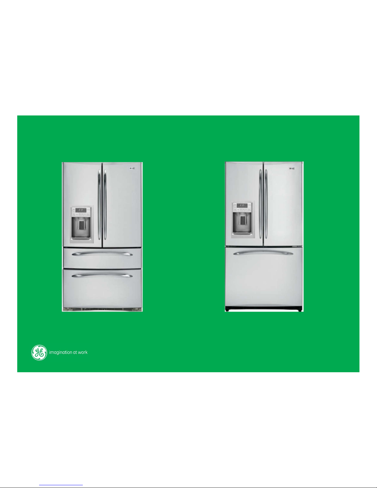
Door – Drawer Section - Structure
Page 65
Copyright General Electric 2011
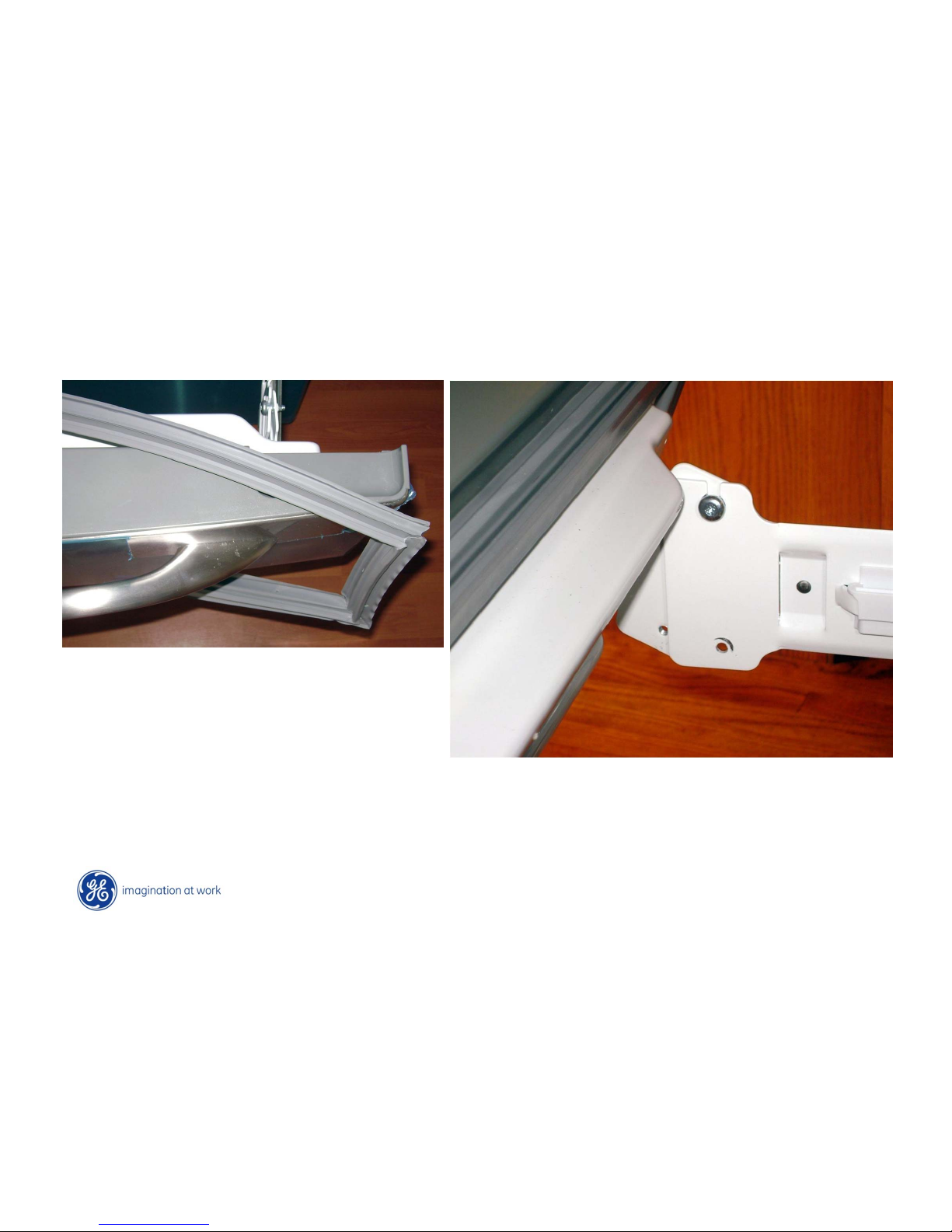
Top Freezer Drawer
Gasket can be easily removed by
peeling away from inner panel and
sliding over the outer panel.
Remove outer panel by removing the lower
T30 torx screw. Loosen the top one and lit
panel up and off.
Page 66
Copyright General Electric 2011
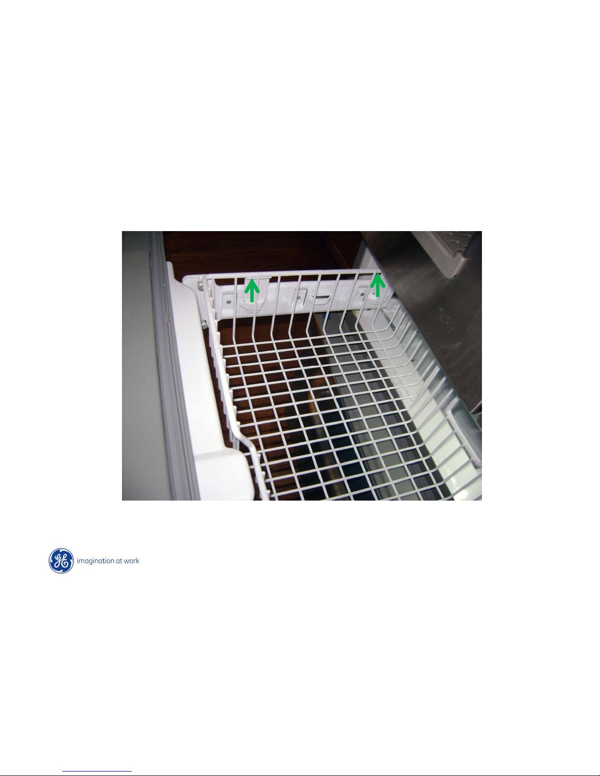
Top Freezer Drawer
Top drawer shelf lifts straight up
Page 67
Copyright General Electric 2011
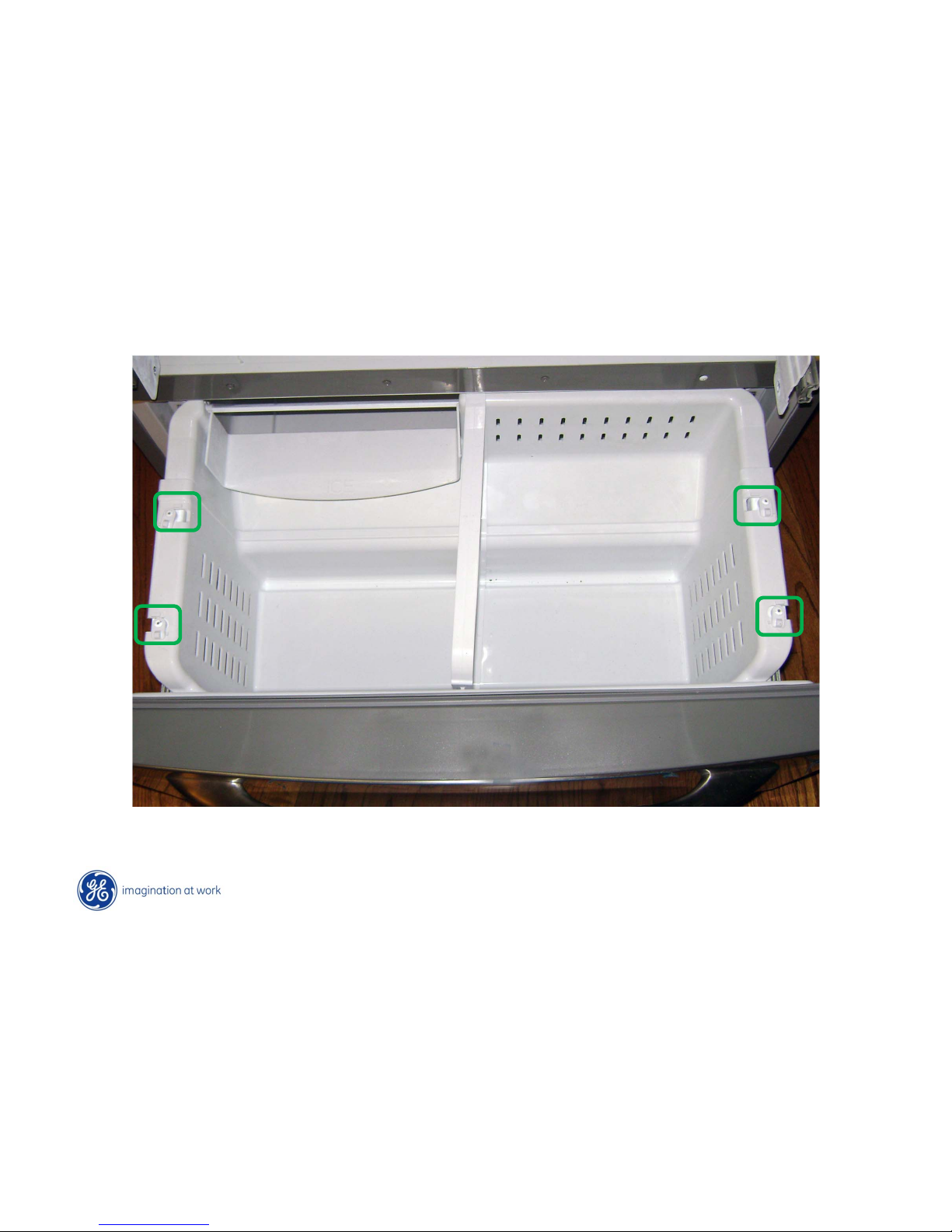
Lower Freezer Drawer
4-Swing locks ; Set to “unlock” position and lift freezer basket up and out
Page 68
Copyright General Electric 2011
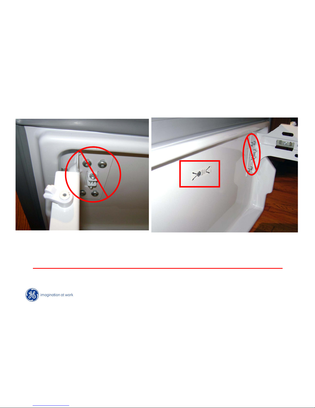
Lower Freezer Drawer
To remove lower drawer front; DO NOT remove the front panel screws!!!!!
Stop
STOP !!!!!
Page 69
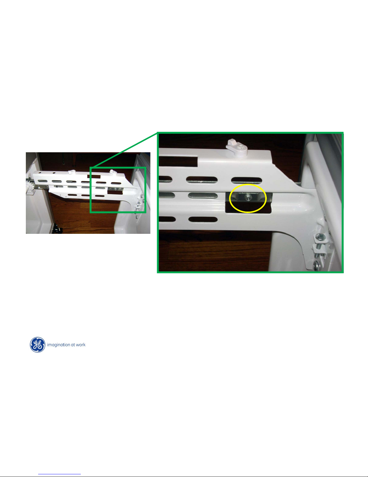
Copyright General Electric 2011
Lower Freezer Drawer
Remove ¼ hex head screw from each side
Page 70
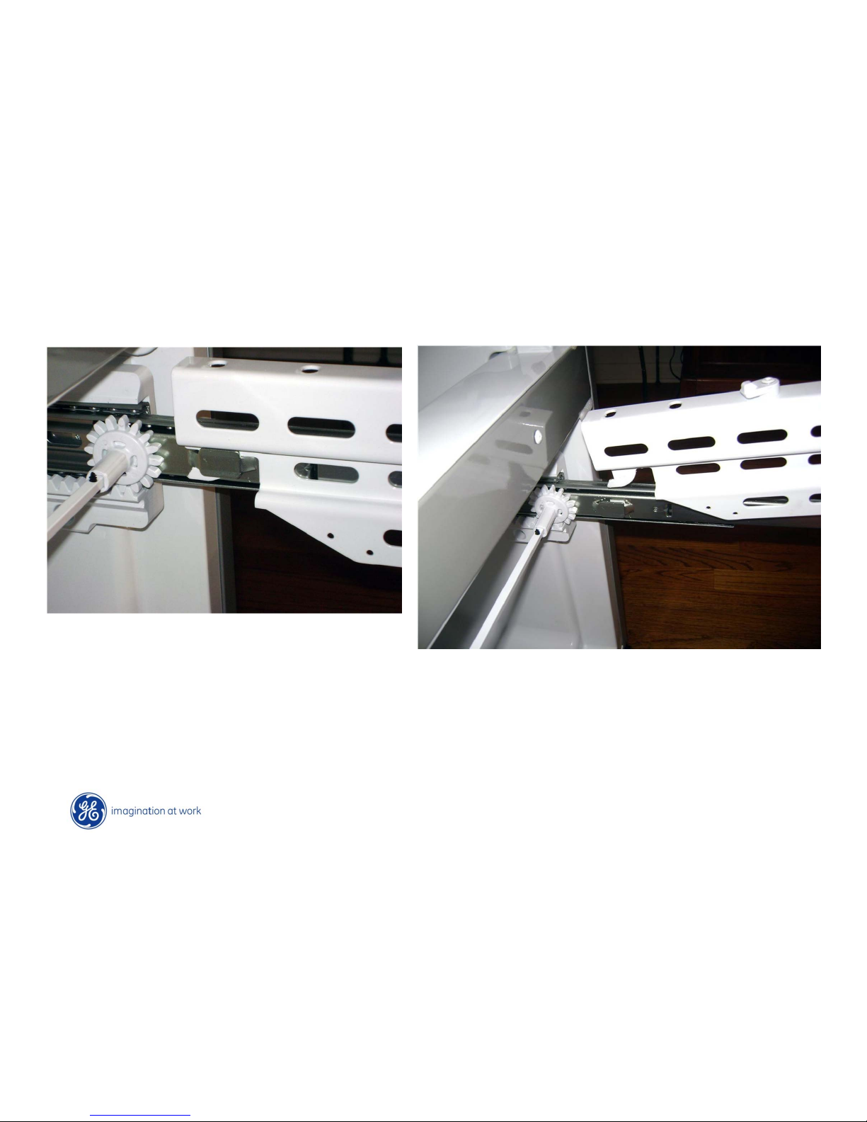
Copyright General Electric 2011
Lower Freezer Drawer
With both screws removed, lift up on drawer front and disengage from
rear slots.
Page 71
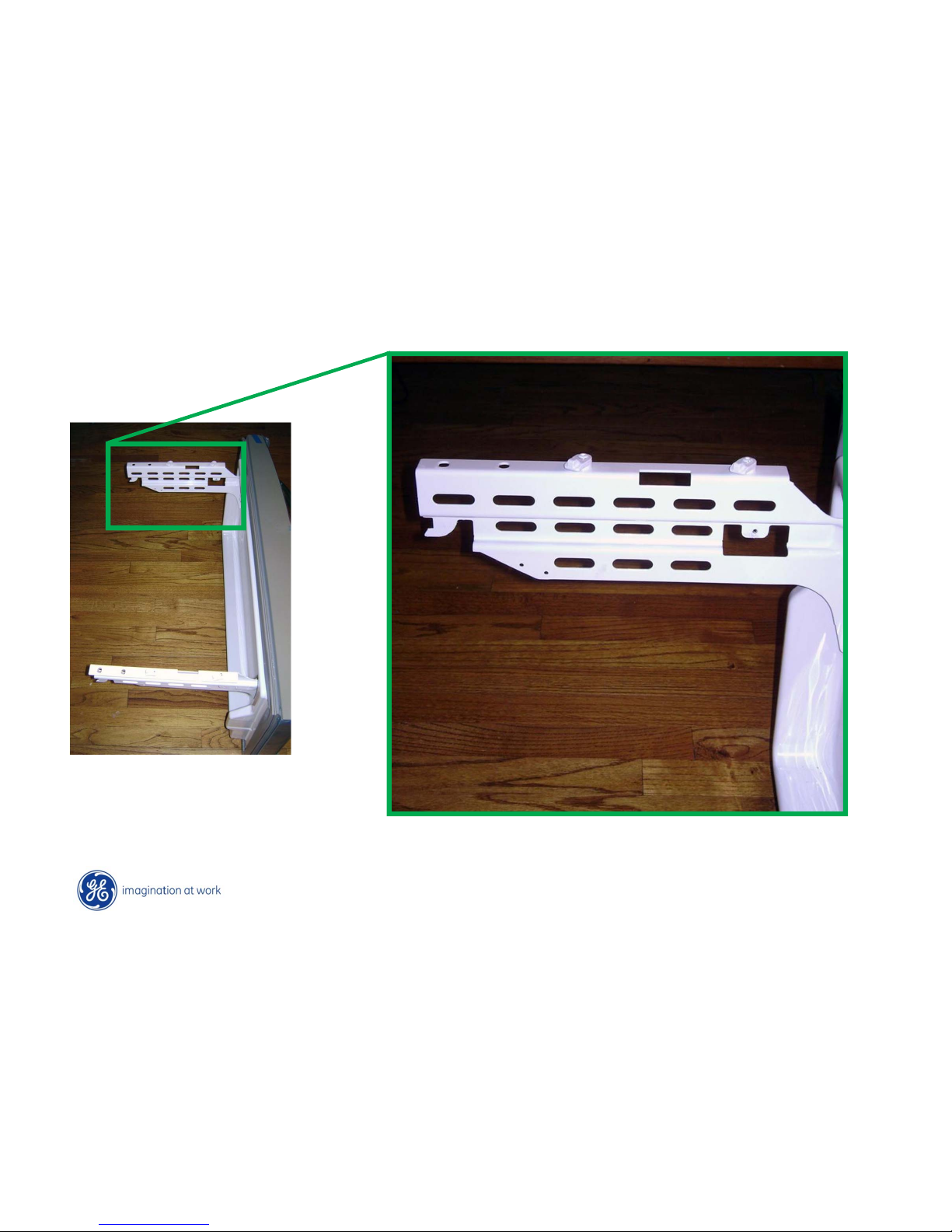
Copyright General Electric 2011
Lower Freezer Drawer
Reassemble by engaging rear tabs first and then re-install two screws
Page 72
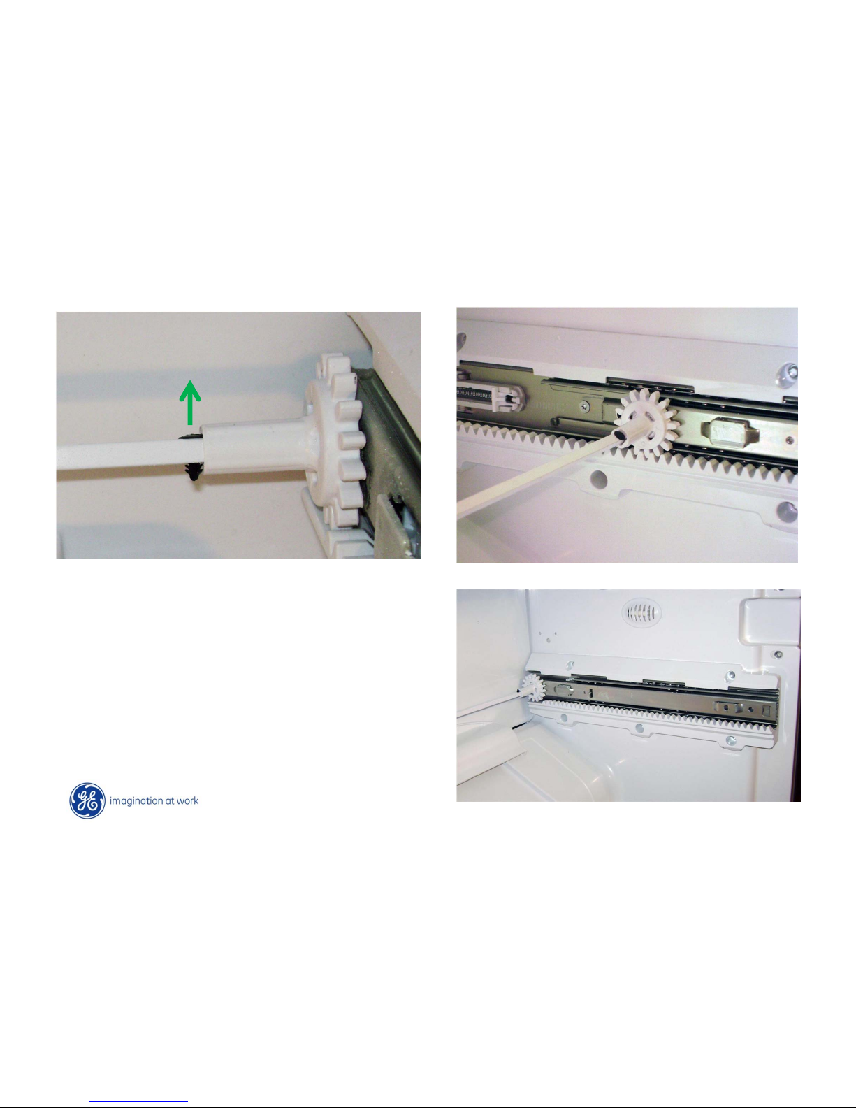
Copyright General Electric 2011
Freezer Drawer Track
To remove side wall tracks, start by removing
the roller guide bar. Remove small black
locating pin and slide bar to right and remove
from rollers.
NOTE: For best results when re-installing start
with roller in rear location.
Remove 5 screws to remove track from inner
liner .
Page 73
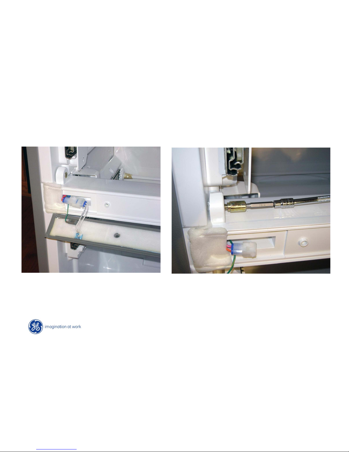
Copyright General Electric 2011
Freezer Mullion
Remove 4 screws securing mullion heater
and face plate.
To replace mullion bar assembly, use T30 torx.
Page 74
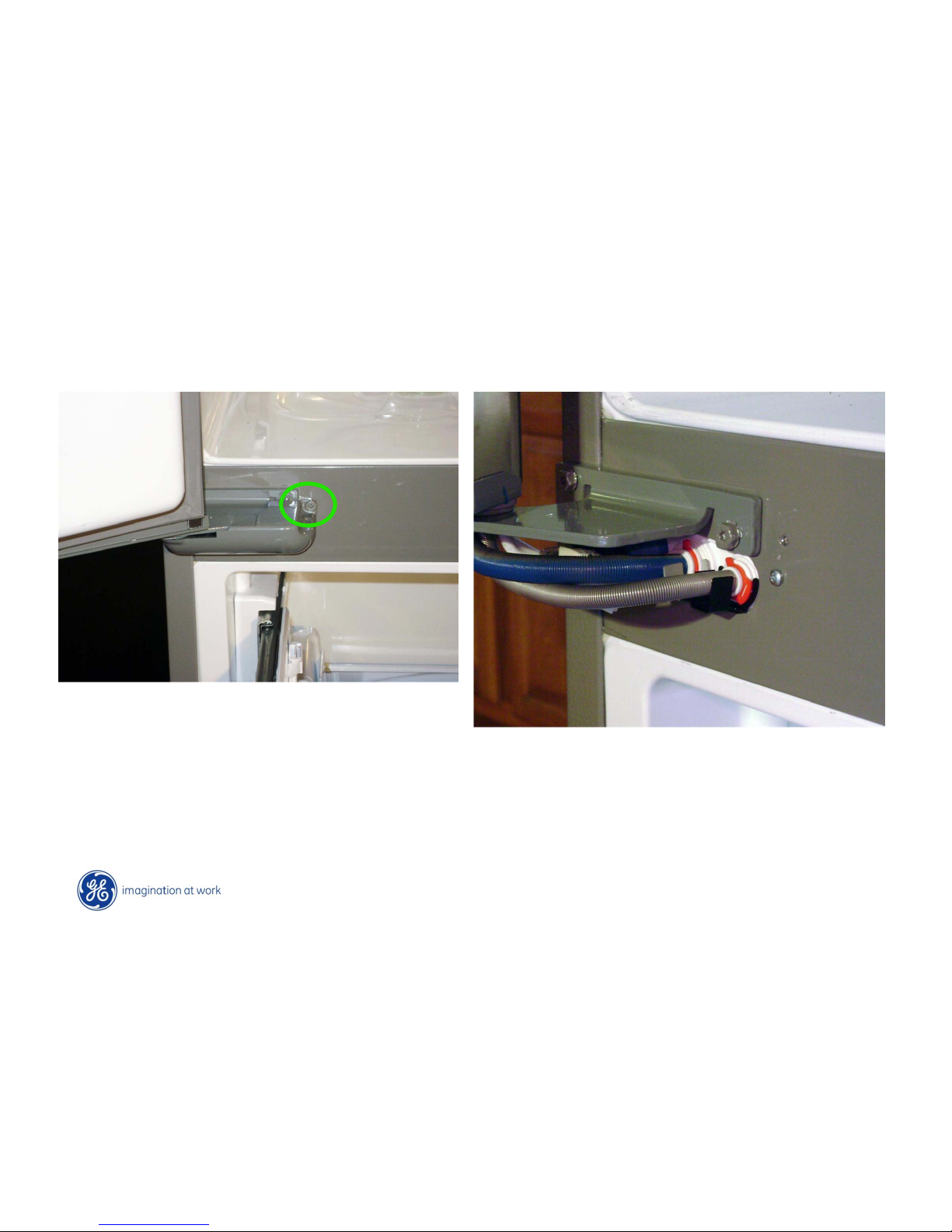
Copyright General Electric 2011
Fresh Food Left door with Ice/Water
Remove 1 screw securing cover
Remove cover
Page 75
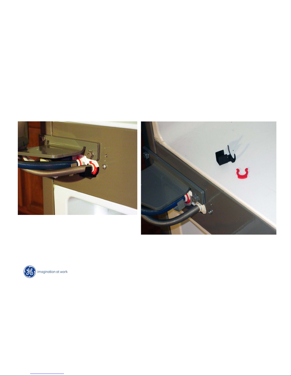
Copyright General Electric 2011
Fresh Food Left door with Ice/Water
Remove black shield and red clip for each water line
Page 76
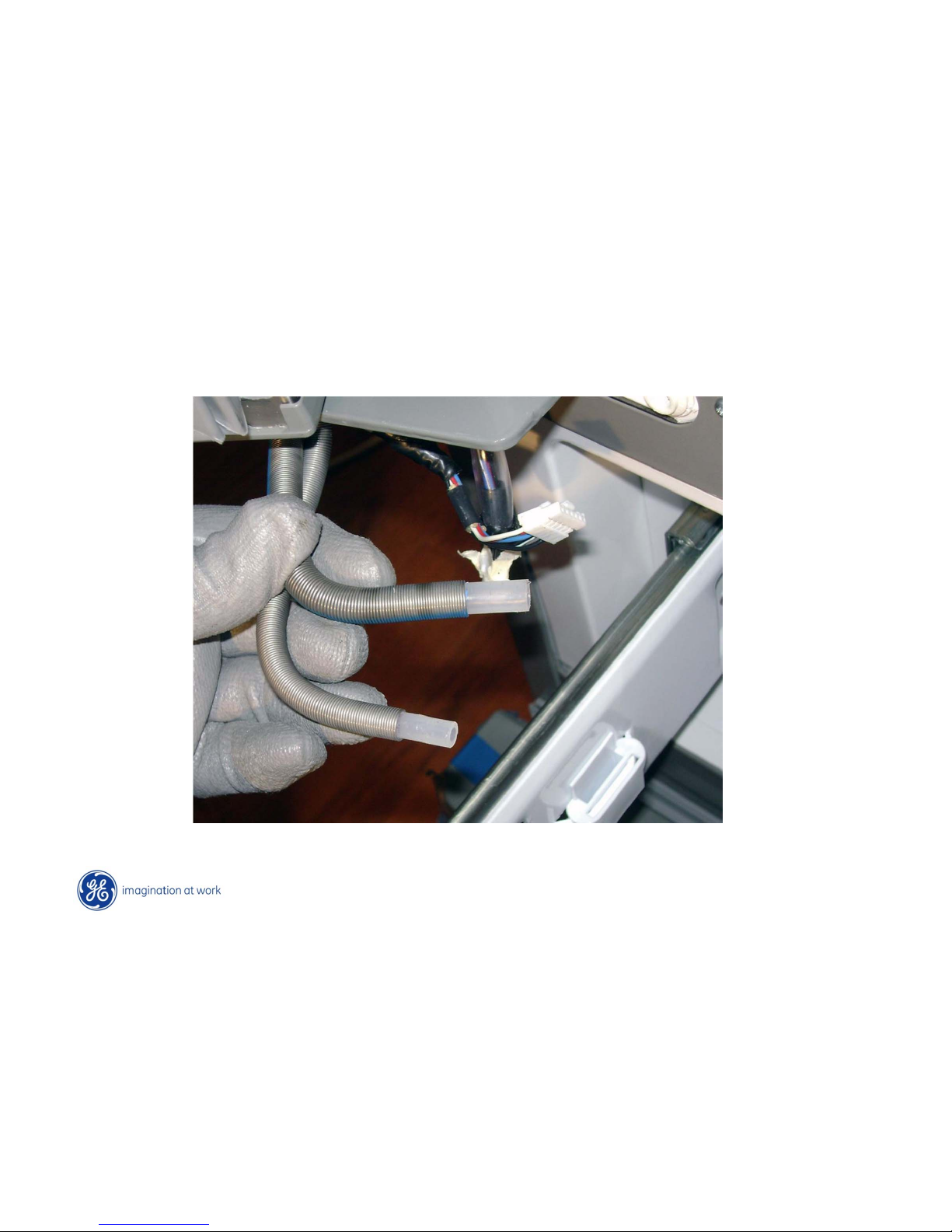
Copyright General Electric 2011
Fresh Food Left door with Ice/Water
NOTE: Water line is larger diameter than IM line
Page 77
Copyright General Electric 2011
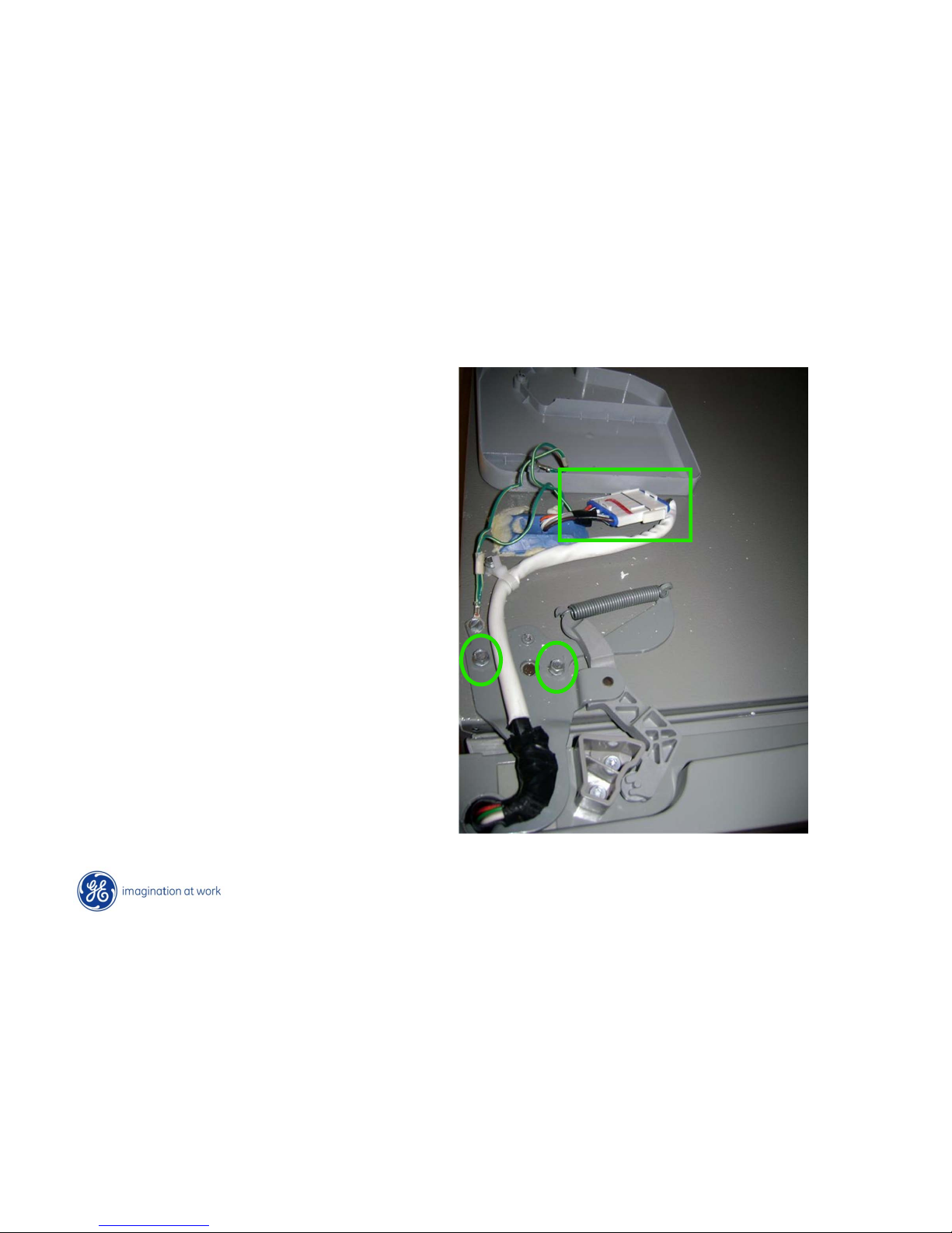
Fresh Food Left Door
Remove 1 Phillips-head screw holding
hinge cover.
Remove 2 5/16 hex head screws
Disconnect wiring harness
Page 78
Copyright General Electric 2011
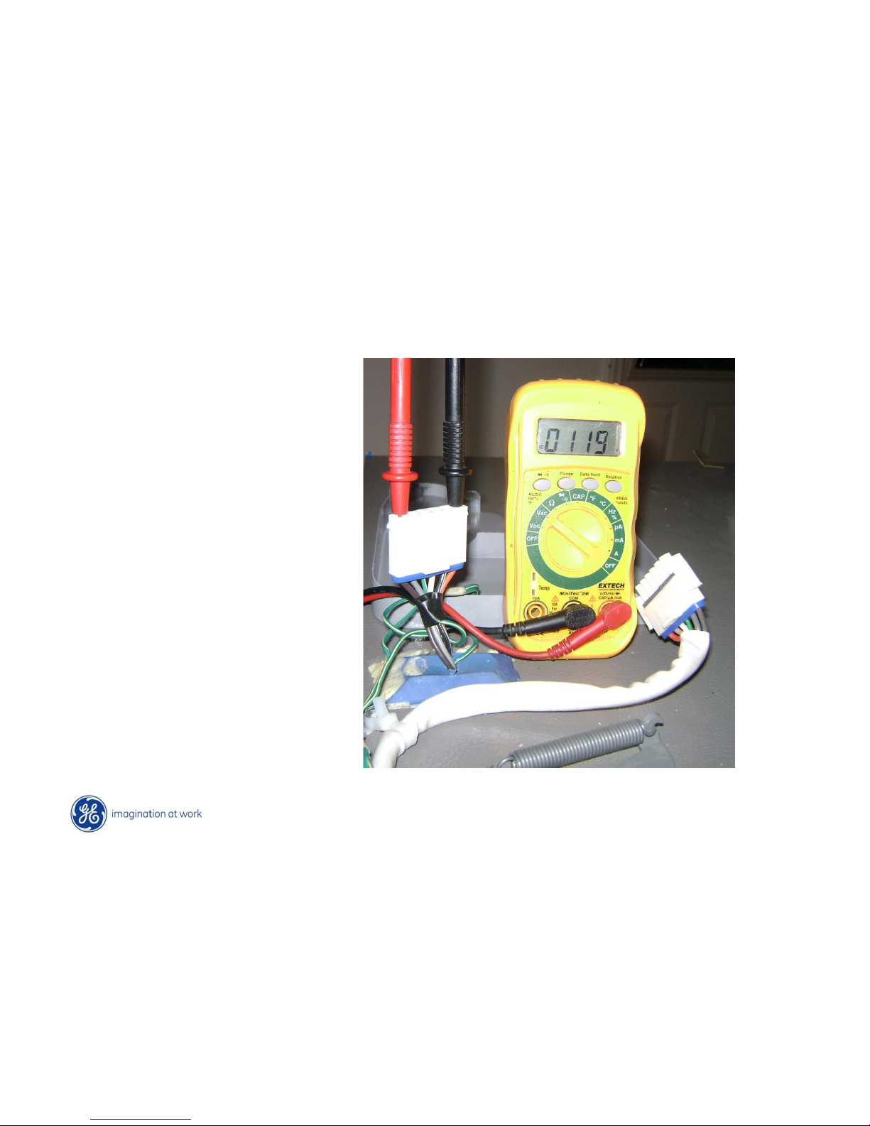
Fresh Food Left Door
Testing for IM supply and
auger motor voltages can be
accomplished at the top plug
Page 79
Copyright General Electric 2011
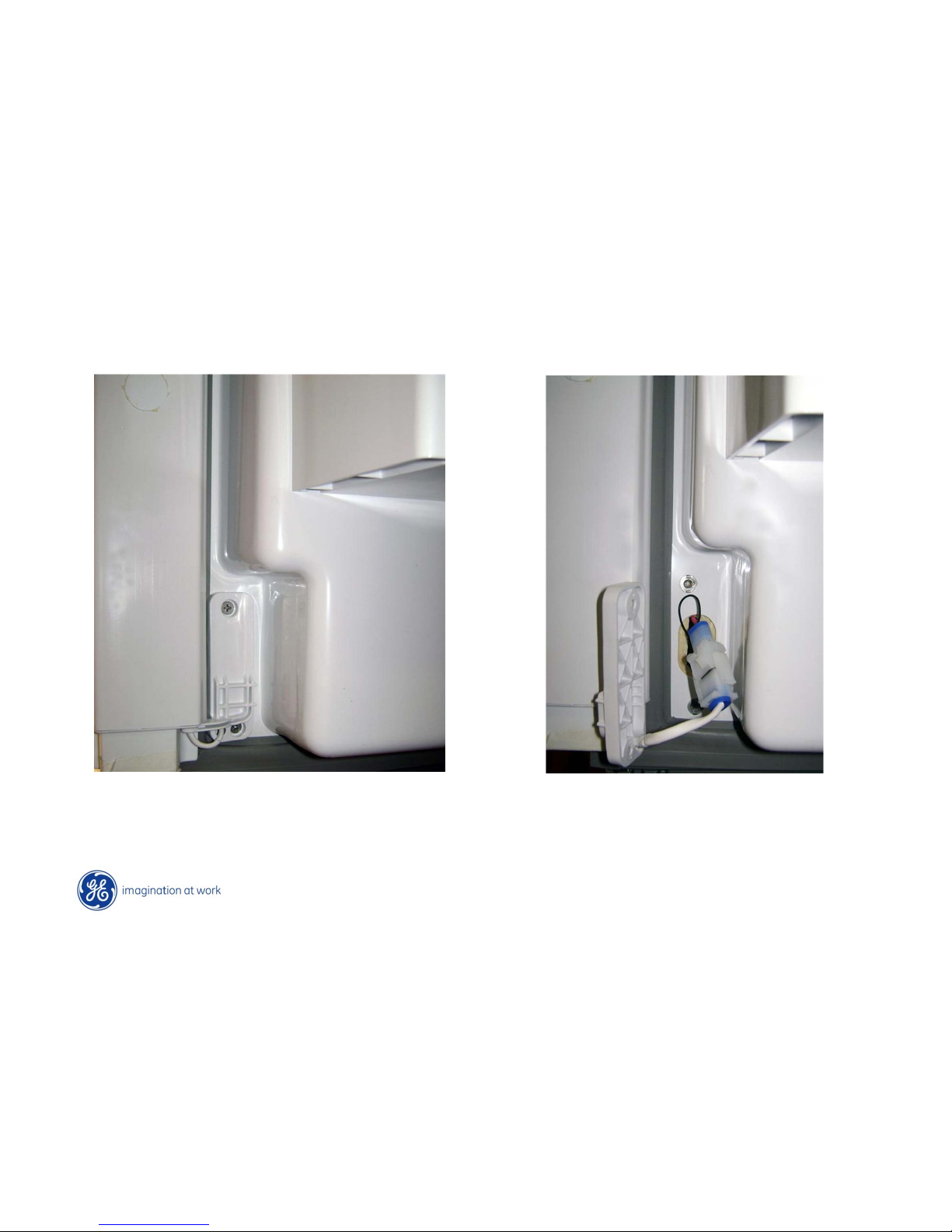
Vertical (Articulating) Mullion Heater
Remove 2 Phillips-head screws.
Check heater for 24 Ω resistance or 13 VDC
(voltage only present if heater should be on)
Page 80
Copyright General Electric 2011
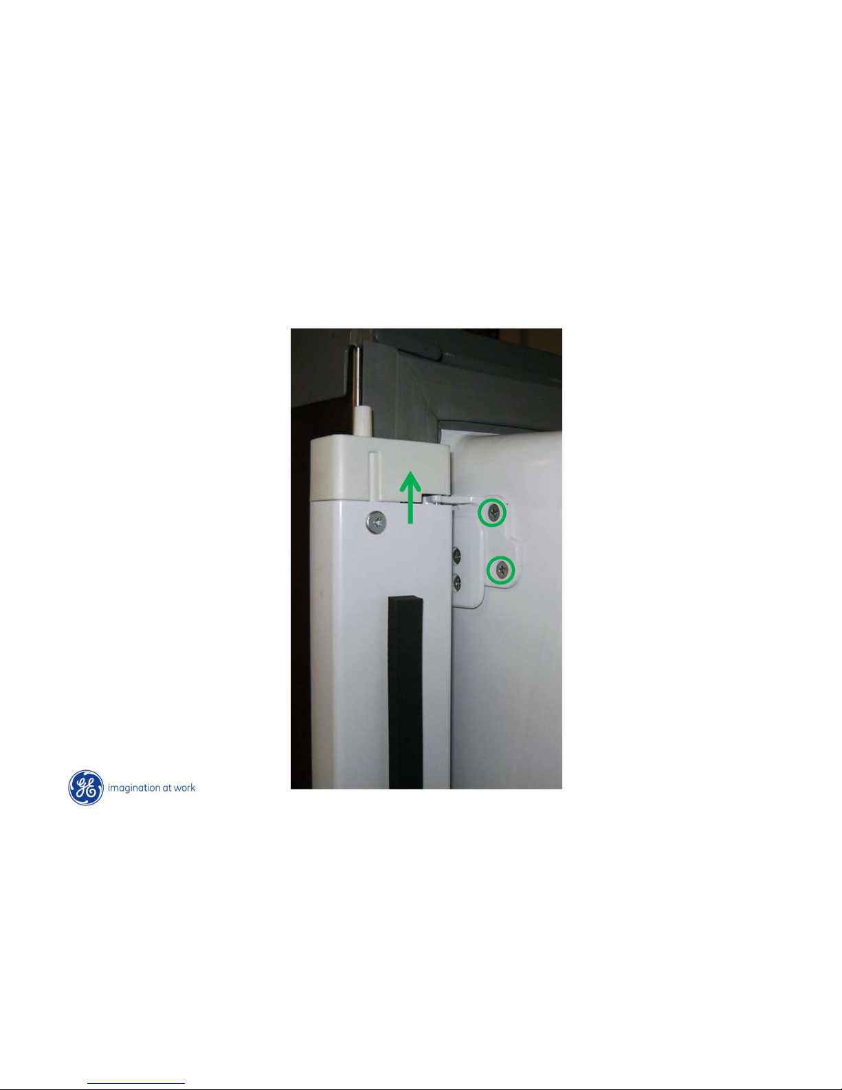
Vertical (Articulating) Mullion Heater
Remove 2 Phillips-head
screws and lift off
Page 81
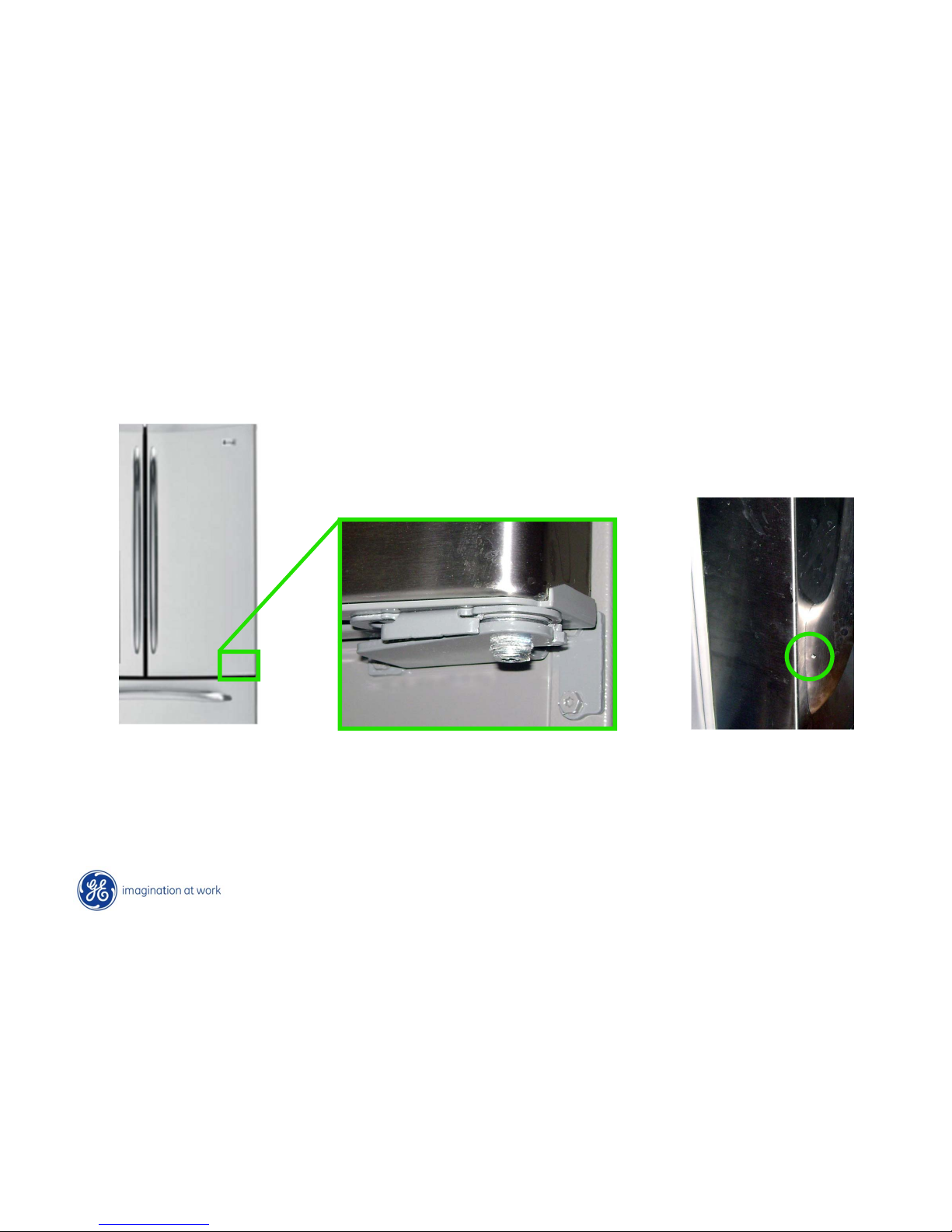
Copyright General Electric 2011
Fresh Food Right Door
3/32 Allen screw
for handle removal
¼ Allen adjustment screw
Page 82
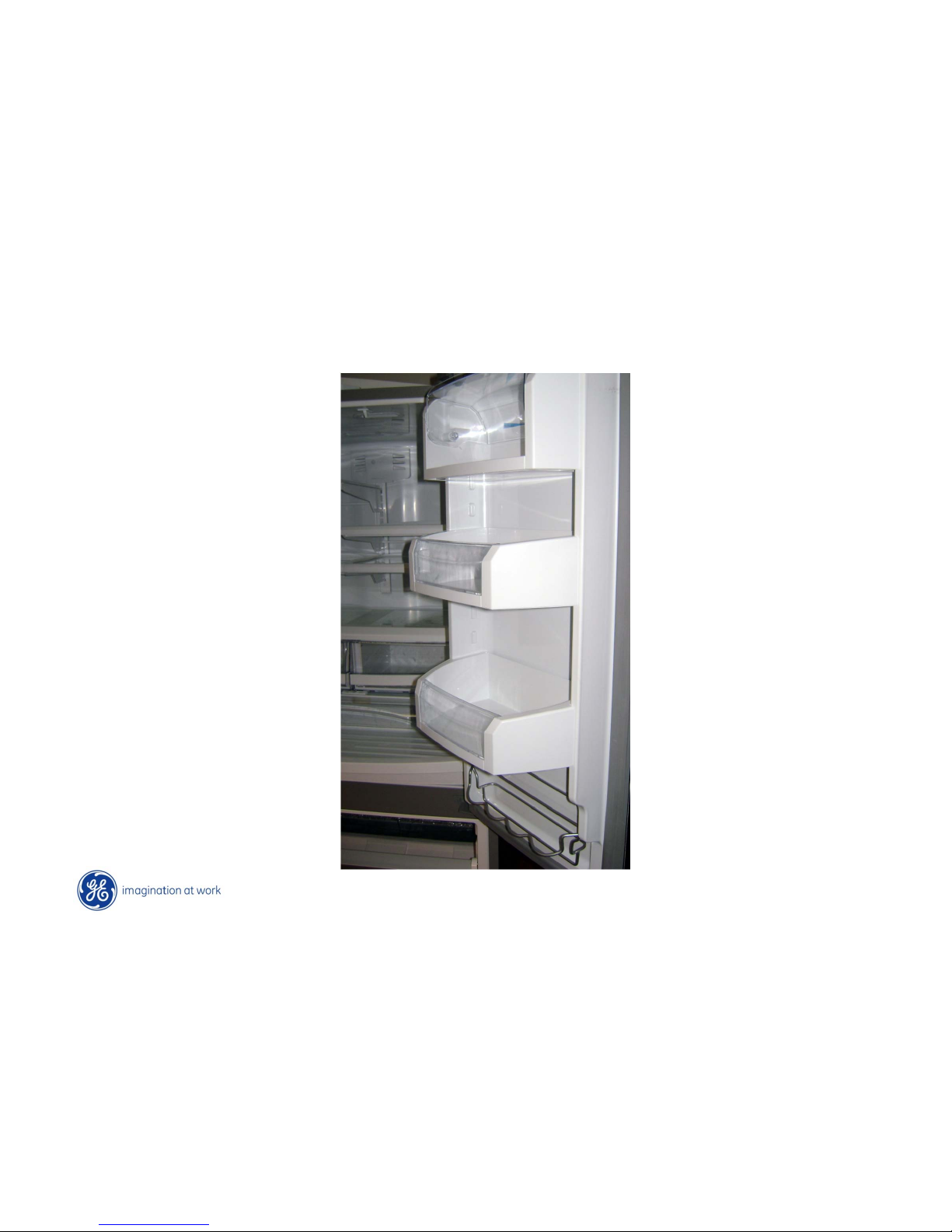
Copyright General Electric 2011
Fresh Food Right Door
Deep large bins on door.
Page 83
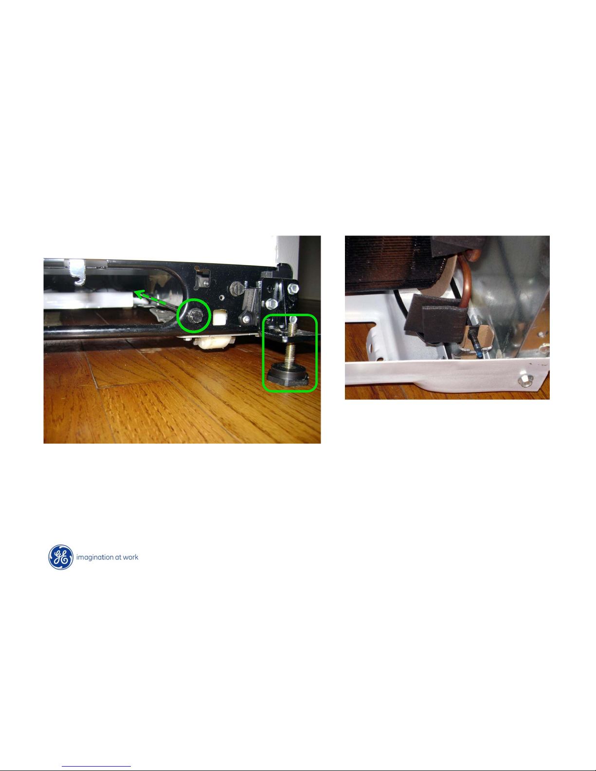
Copyright General Electric 2011
Level Legs - Rollers
NOTE: Adjusting refrigerator pitch too far back could cause IM water leak inside ice bucket
Rear View
Front View
Rear roller adjusted with 3/8 hex head rod
Front level legs adjustable.
Page 84
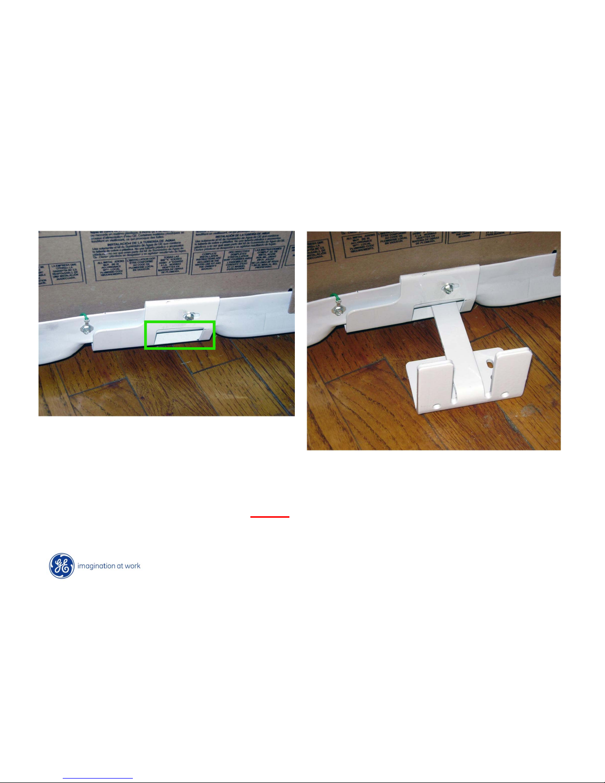
Copyright General Electric 2011
Anti T ip Device
Anti-tip bracket mounts to floor or wall
Anti-tip bracket fits into opening when
refrigerator is slid back into place.
• Anti-Tip Device MUST be installed when supplied.
• Additionally at least 2 screws must be used.
Page 85
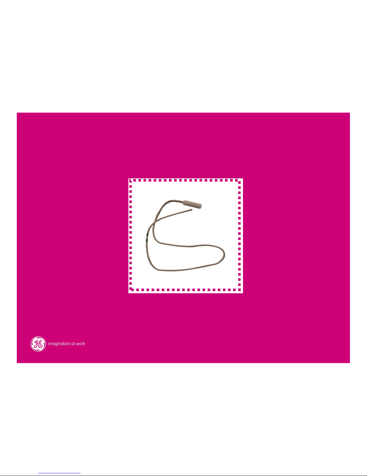
Thermistors
Page 86
Copyright General Electric 2011
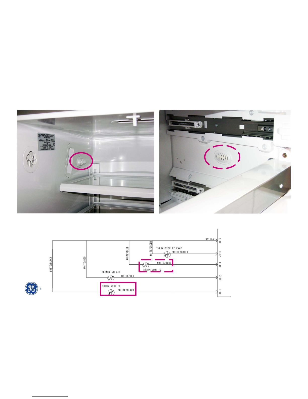
FF Thermistor located on top left side wall
Tested at J1 connector of main board
FZR Thermistor located on right side wall
Tested at J1 connector on main board
Thermistors – FF & FZ
Page 87
Copyright General Electric 2011
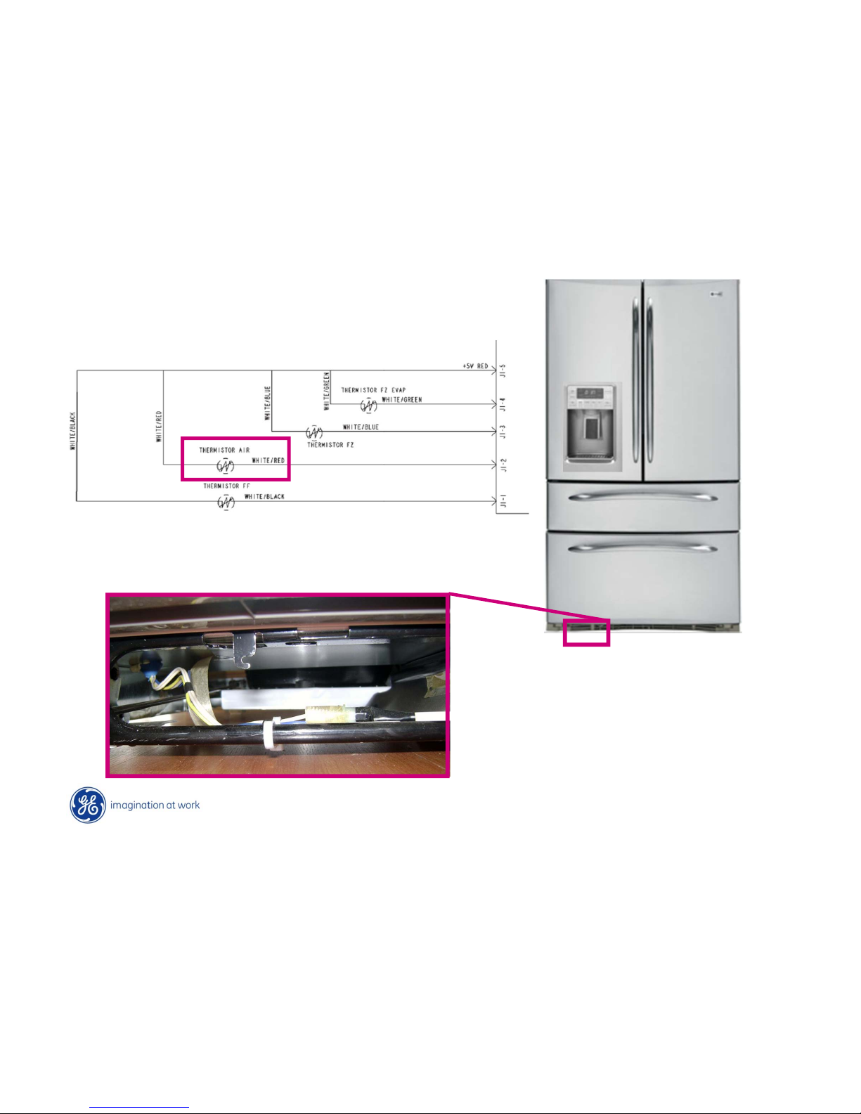
• Ambient Thermistor located on front lower
left.
• Main board uses data from ambient
thermistor to recalculate target temperatures
under adverse environmental conditions.
• No adjustment if thermistor fails.
Thermistors - Ambient
Page 88
Copyright General Electric 2011
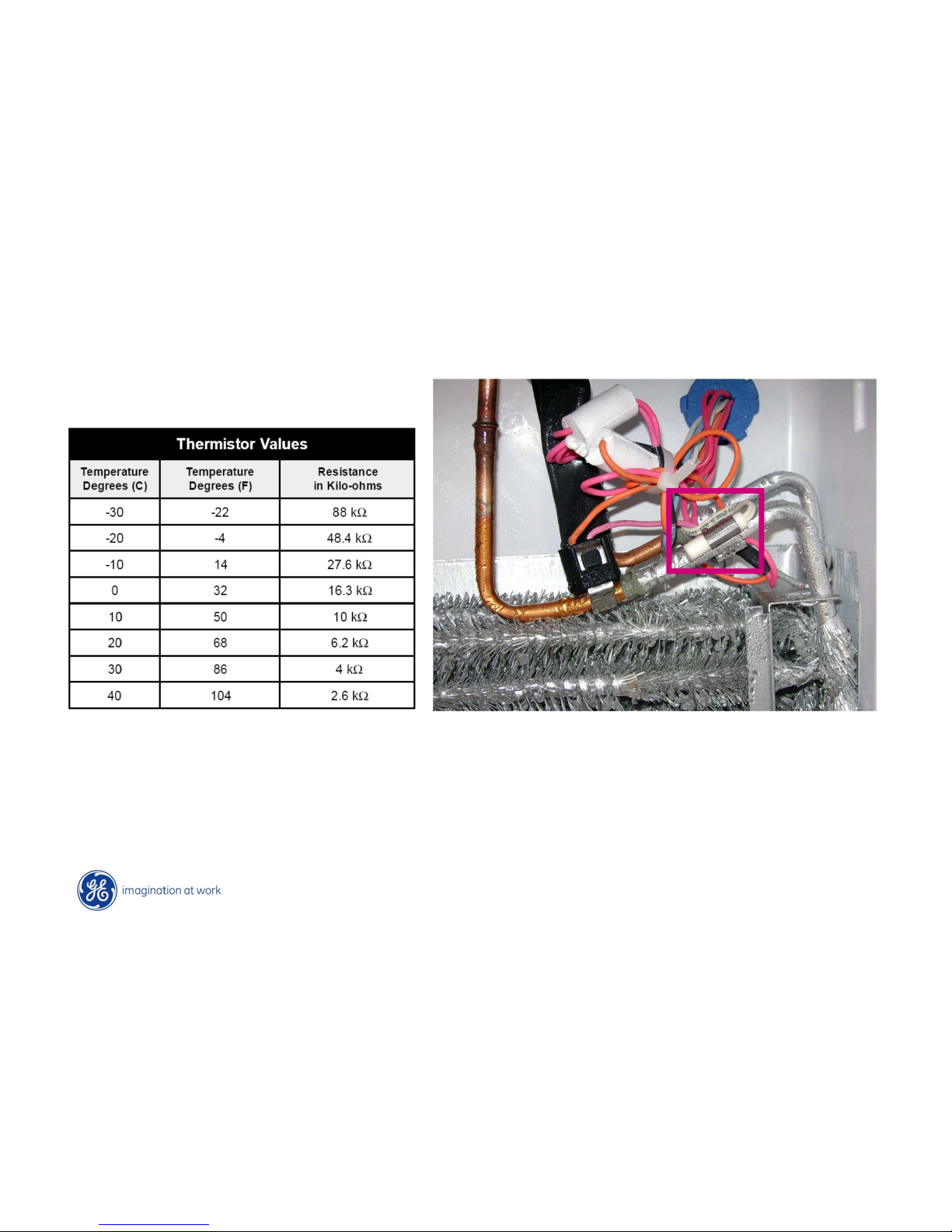
Thermistors - Evaporator
Evaporator thermistor clipped to tubing.
NOTE: Safety Thermostat
Page 89
Copyright General Electric 2011
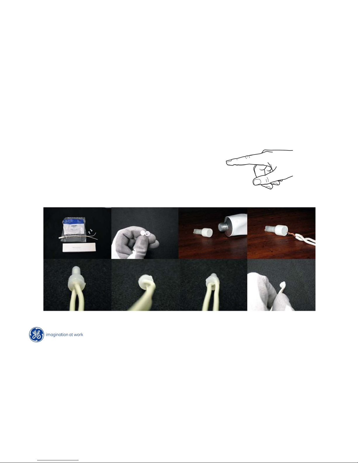
WR97X163 Silicone grease
WR01X10466 Bell Connector
Thermistors - Replacing
Page 90
Copyright General Electric 2011
Humidity Sensor
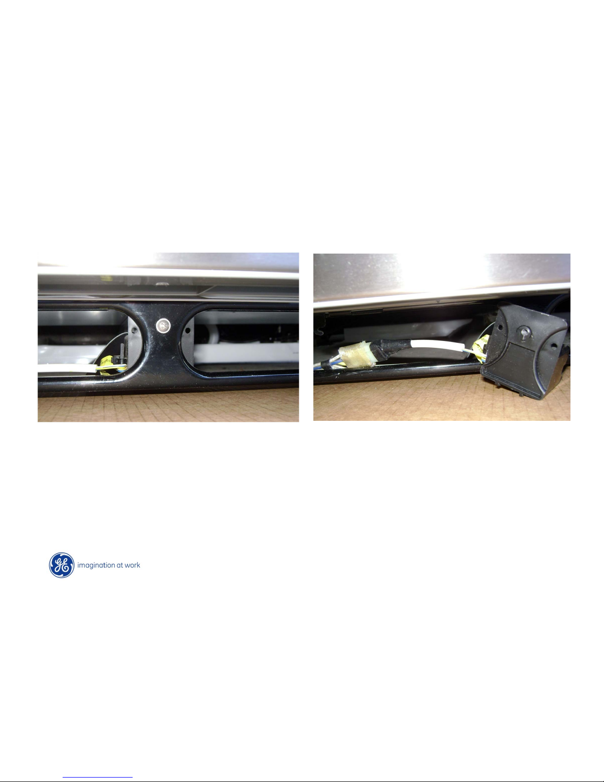
• Humidity Sensor is located behind the front grill at the bottom of the
refrigerator.
• Approximately in the center of the lower rail.
• It is held in place with one Phillips-head screw
(Front grill removed)
Page 91
Copyright General Electric 2011
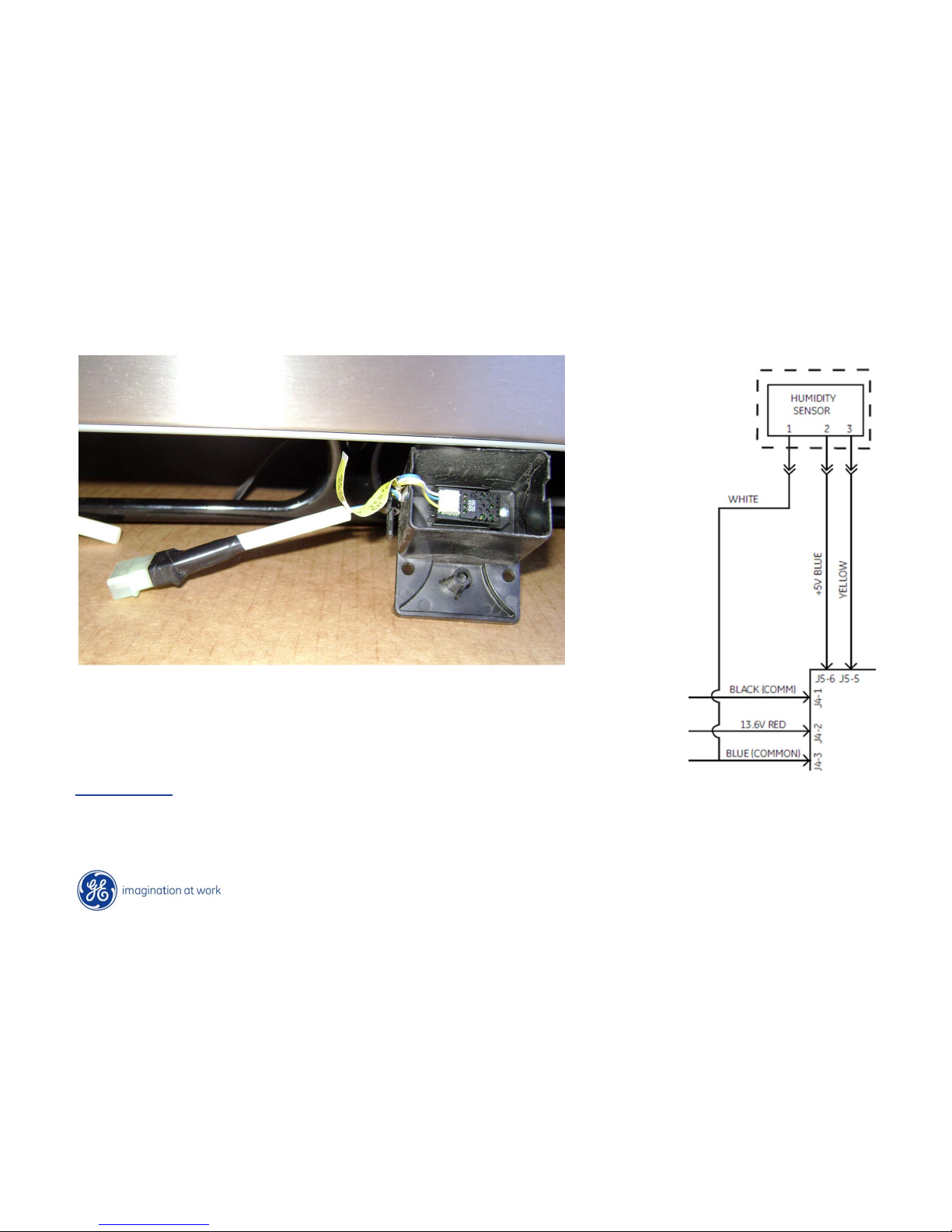
Humidity Sensor - Testing
Pins 1 to 2 --- constant 5 vdc.
Pins 1 to 3 --- varies with humidity from about 1.11 vdc to 3.62 vdc.
The higher the humidity the higher the output voltage. Any output
higher than @ 4 vdc or lower than 1 vdc, the sensor is bad
F.I. Testing – A reading of appx 0-100 would be considered normal.
A reading of 150 or higher indicates a failed humidity sensor.
NOTE: A failed sensor could keep the heaters on for longer periods.
Page 92
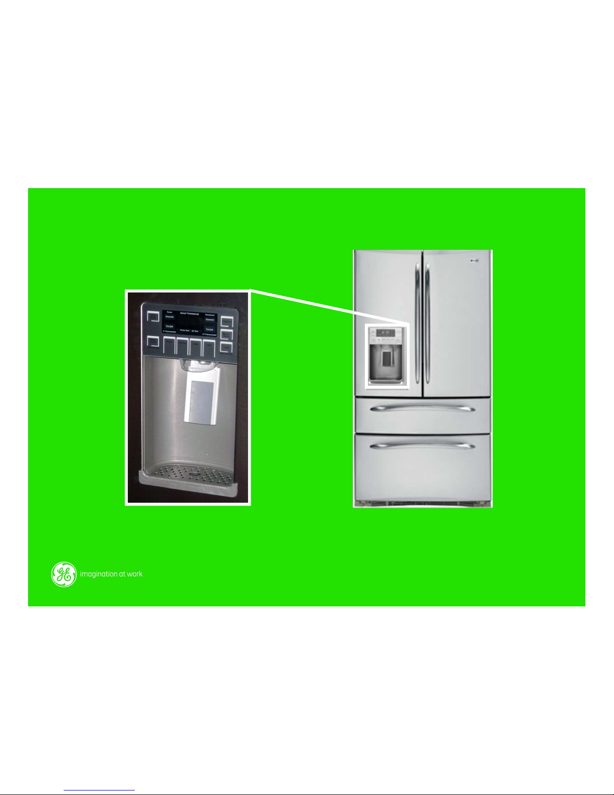
Main Control Board and
Dispenser Board
Page 93
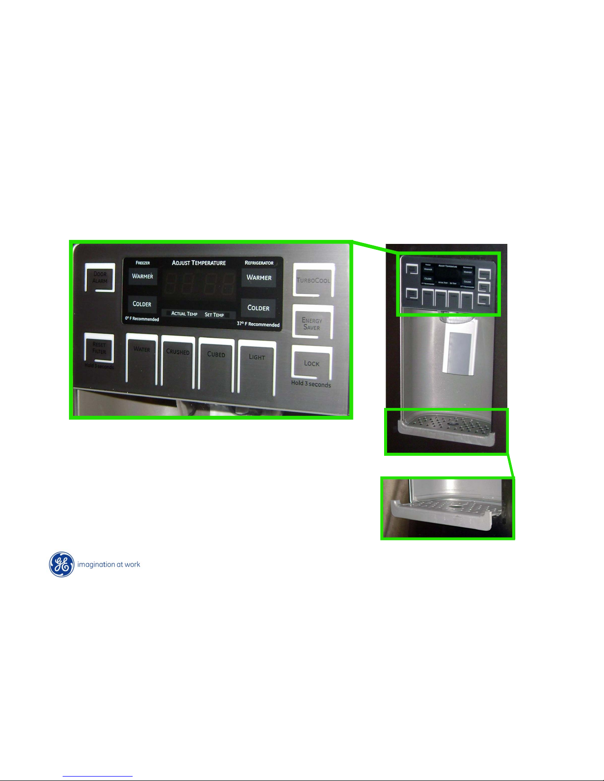
Copyright General Electric 2011
Dispenser Board
Pull out at the bottom to release tabs.
Dispense tray slides forward
Page 94
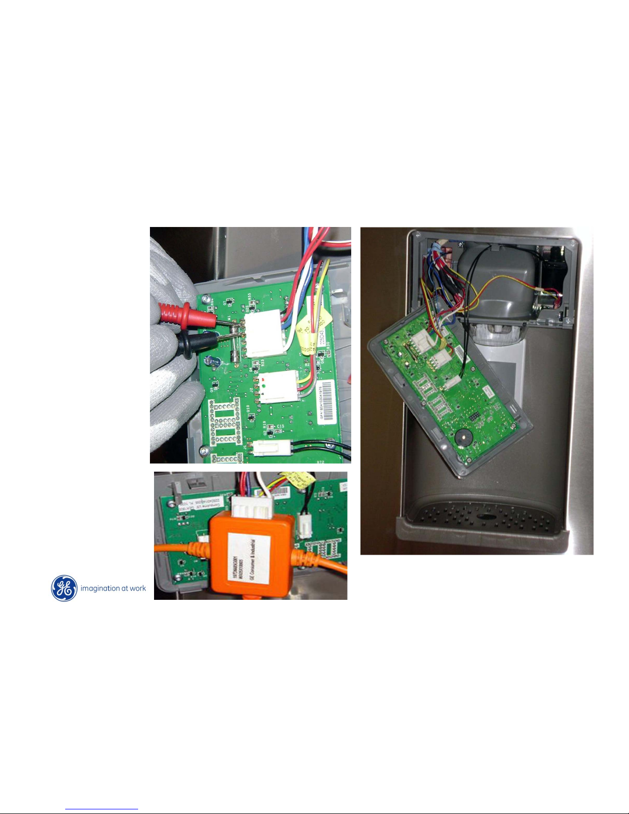
Copyright General Electric 2011
Dispenser Board
Testing for
13VDC supply
voltage at Blue
&Red pins.
Black is
Communication
Page 95
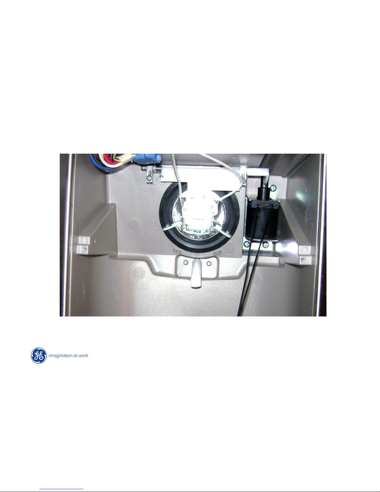
Copyright General Electric 2011
Dispenser Board
Duct door heater location
Page 96
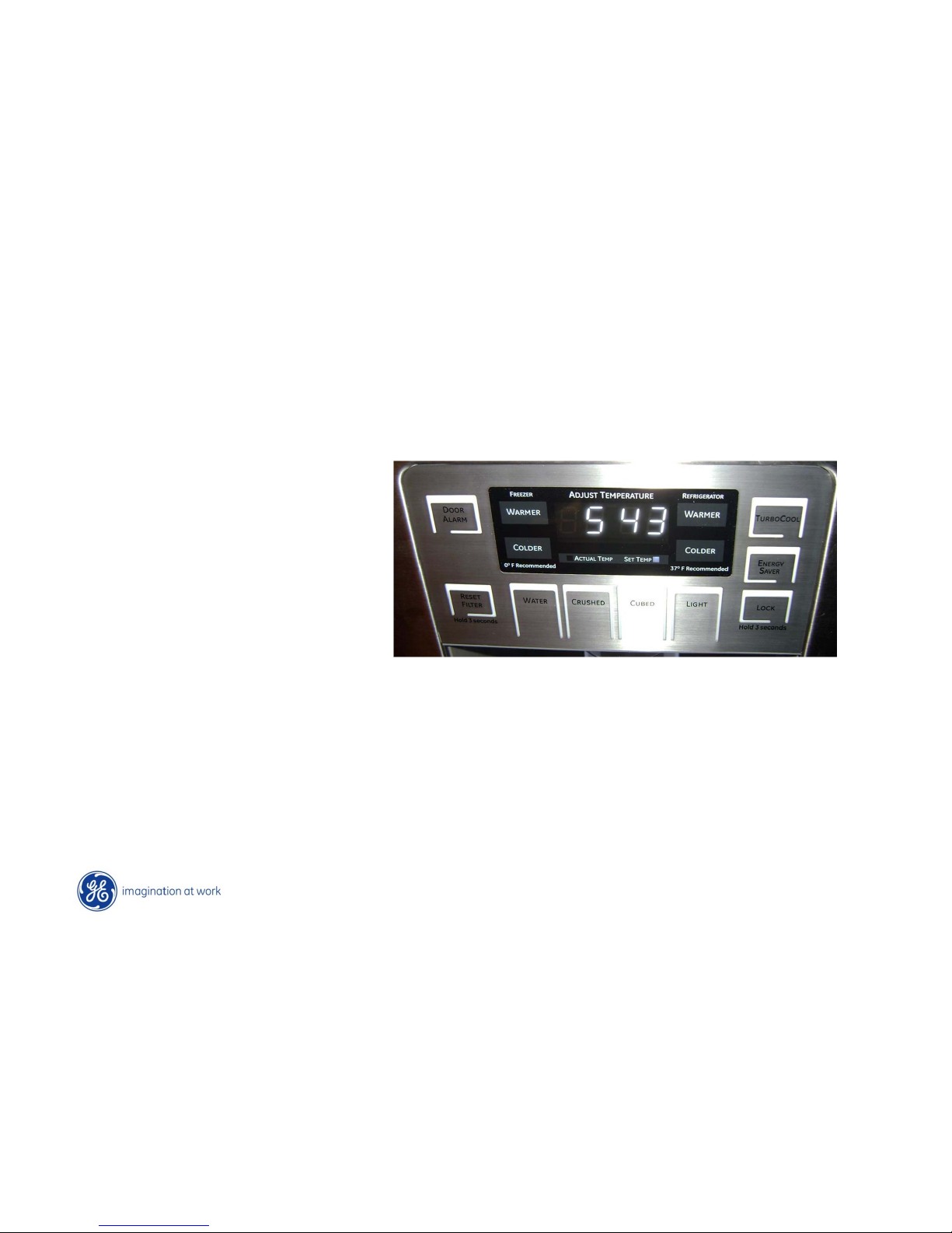
Copyright General Electric 2011
Dispenser Board – Off position
To turn refrigerator “Off”
consumer has to turn BOTH
settings to the warmest AND
while control is beeping.
Once one section is turned to
“highest” setting and then the
other is also set to warmest, the
control starts to beep. If
customer waits for beeping to
stop before pressing warmest
pads again, the unit will stay ON
and in the warmest setting for
both sides
Page 97
Copyright General Electric 2011
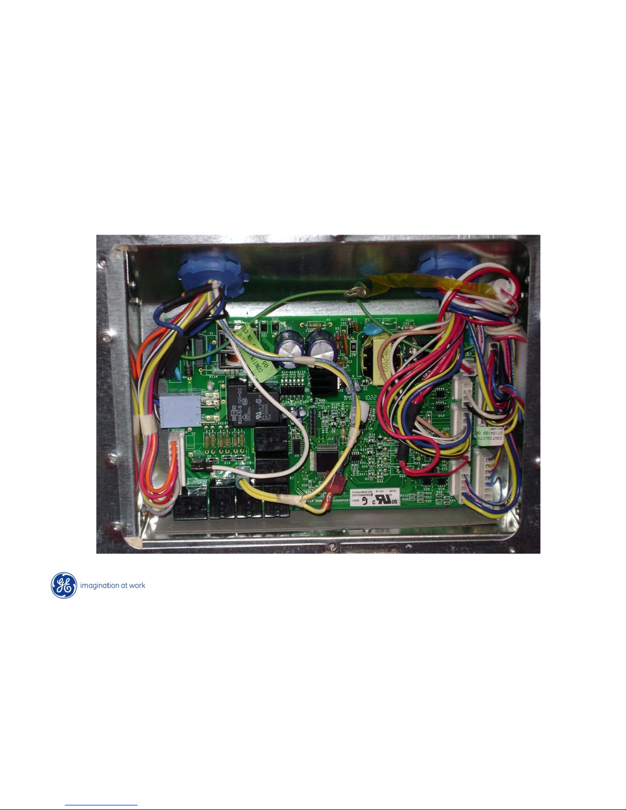
Main Control Board
Page 98
Copyright General Electric 2011
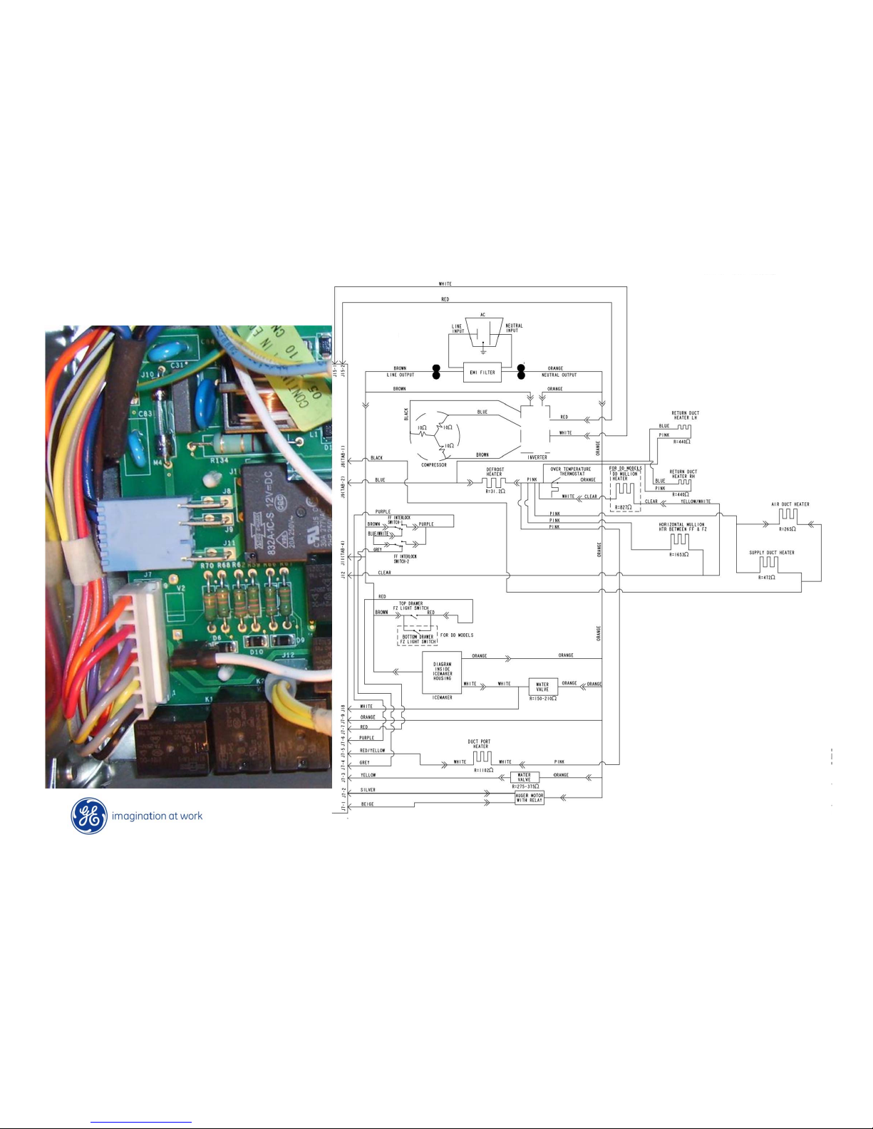
Main Board - A/C
Page 99
Copyright General Electric 2011
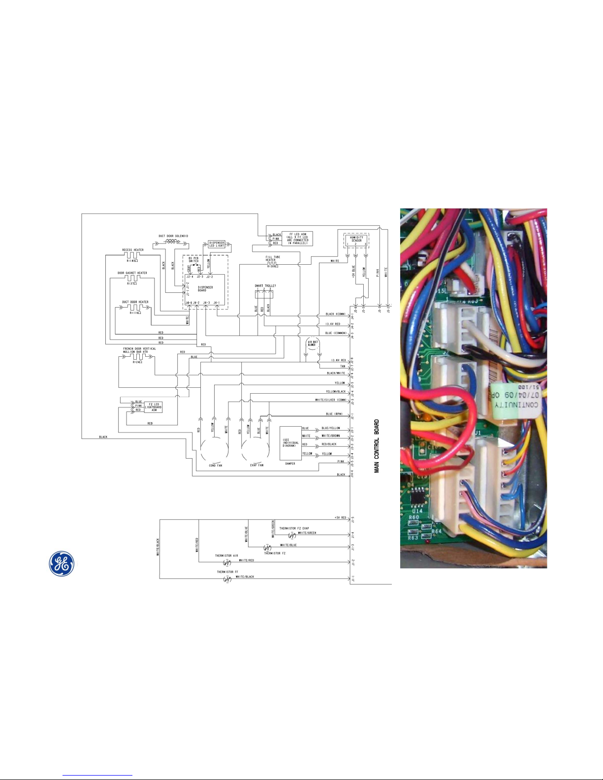
Main Board - D/C
Page 100
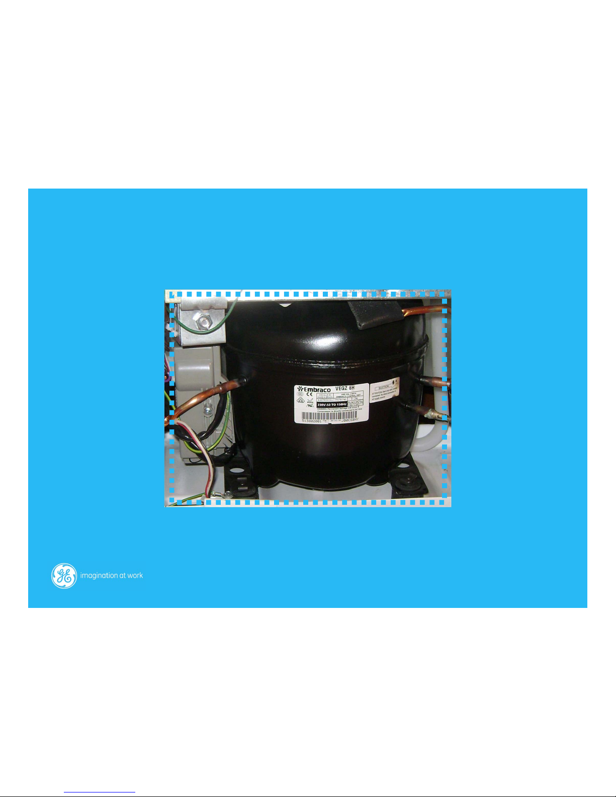
Compressor & Inverter
 Loading...