

GE PFDS450EL3WW, PFDS450EL2WW Owner’s Manual
GEAppliances.com
Safety Instructions ........... 2-4
oi
L_
Operating Instructions
Controls ........................... 5-8
Cycle Options .................... 9, 10
Smart Appliance .................... 15
Dryer Features .................. 10, 11
.
Ouick Start Guide .................... 5
Settings Option ...................... 10
Using the Dryer ..................... 11
Installation Instructions
Before You Begin ................ 14, 15
Connecting the Inlet Hoses ......... 17
Connecting a Gas Dryer ......... 18-21
Connecting an
Electric Dryer .................... 22-24
Exhausting the Dryer ............ 25-31
Final Setup .......................... 32
Installing the Pedestal ........... 43-45
Location of your Dryer .......... 1S,16
Reversing the Door Swing ....... 33-39
Stacking the Washer
and Dryer ....................... 40-42
La section frangaise commence la page 52
S cheuses
PFDS450
PFDS455
PFDN440
PFDN445
PFMS450
PFMS455
PFMN440
PFMN445
Profile
Troubleshooting Tips....... 46-49
Secadoras
Profile
Consumer Support
Consumer Support ........ Back Cover
Warranty (Canada) ................. 51
Warranty (U.S.)..................... 50
La secci6n en espafiol empieza en la p6gina i04
SAVE THESEINSTRUCTIONS
Write the model and serial
numbers here:
Model #
Serial #
They are on the label on the front
of the dryer behind the door.
PrintedinMexico 234D2020PO02 49-90472 03-23 GE
IMPORTANT SAFETY INFORMATION.
READ ALL INSTRUCTIONS BEFORE USING.
A WARNING!
Foryour safety, the information in this manual must be followed to minimize the risk
of fire or explosion, electric shock, or to prevent property damage, personal inJury, or
death.
m Do not store or use gasoline or other
flammable vapors and liquids in the
vicinity of this or any other appliance.
m Installation and service must be
performed by a qualified installer,
service agency or the gas supplier.
WHAT TO DO IF YOU SMELL GAS"
[-_ Do not try to light a match, or cigarette,
or turn on any gas or electrical
appliance.
[_ Do not touch any electrical switch; do
not use any phone in your building.
F_ Clear the room, building or area of all
occupants.
California Safe Drinking Water and Toxic Enforcement Act
Thisact requiresthe governor of California to publish a list of substances known to the state to cause cancer,
birth defects or other reproductive harm and requires businessesto warn customers of potential exposure to
such substances.
Gasappliances cancause minor exposureto four ofthese substances,namely benzene,carbon monoxide,
formaldehyde and soot, caused primarily by the incompletecombustion of natural gas or LPfuels.
[] immediately call your gas supplier
from a neighbor's phone. Follow the
gas supplier's instructions carefully.
F-_if you cannot reach your gas supplier,
call the fire department.
Properlyadjusted dryers will minimize incomplete combustion. Exposureto these substances can be minimized
further by properlyventing the dryer to the outdoors.
PROPERINSTALLAWON
This dryer must be properly installed and located in accordance with the Installation Instructions
before it is used. Installation Instructions are included in the back of this manual.
[]
Properlyground dryer to conform with oil governing
codes and ordinances. Follow details in Installation
Instructions.
[]
Install or store where it will not be exposed to
temperatures below freezing or exposed to water or
weather.
[] Connect to u properly rated, protected and sized
power supply circuit to avoid electrical overload.
[] Remove all sharp packing items and dispose of all
shipping materials properly.
2 For complete details, follow the Installation Instructions.
Exhaust/Ducting
[_] DryersMUSTbeexhausted to the outside to prevent
large amounts of moisture and lintfrom being blown
intothe room.
Useonly rigid metal 4" diameter ductwork inside the
[]
dryer cabinet. Useonly UL approved rigid metal or
flexible metal 4-in diameter ductwork for exhausting
to the outdoors. Never use plastic or other
combustible, easy-to-puncture ductwork. USE OF
PLASTICOROTHERCOMBUSTIBLEDUCTWORKCAN
CAUSEA FIRE.PUNCTUREDDUCTWORKCANCAUSE
A FIREIF IT COLLAPSESOR BECOMESOTHERWISE
RESTRICTEDIN USEORDURINGINSTALLATION.
IMPORTANT SAFETY INFORMATION.
READ ALL INSTRUCTIONS BEFORE USING. GEApUioncescom
WARNING!
YOUR LAUNDRY AREA
[] Keep the area underneath and around your
appliances free of combustible materials, (lint,paper,
rags, etc.),gasoline, chemicals and other flammable
vapors and liquids.
[]
Keepthe floor around your appliances clean and dry
to reducethe possibility of slipping.
[]
Close supervision is necessary if this appliance is
used byor near children. Do not allow children to play
on,with or inside this or any other appliance.
WHEN USING YOURDRYER
[]
Never reach into the dryer while the drum is moving.
Beforeloading,unloading or adding clothes,wait until
the drumhascompletelystopped.
[]
Clean the lint filter before each load to prevent lint
accumulation insidethe dryeror inthe room.DO NOT
OPERATETHEDRYERWITHOUTTHELINTFILTERIN
PLACE.
[]
Donotwash or dry articlesthat havebeen cleaned in,
washed in,soaked in or spotted with combustible or
explosivesubstances(suchaswax, oil,paint,gasoline, []
degreasers, dry-cleaning solvents, kerosene, etc.).
These substances give off vapors that may ignite or
explode. Do not add these substances to the wash
water. Do not use or place these substances around
your washer or dryer during operation.
[]
Do not place items exposed to cooking oils in your
dryer. Items contaminated with cooking oils may
contribute to a chemical reaction that could cause a
clothes load to catch fire.
[]
Any article on which you have used a cleaning
solvent or that contains flammable materials (such
as cleaning cloths, mops, towels used in beauty
salons, restaurants or barber shops, etc.) must not
be placed in or near the dryer until solvents or
flammable materials have been removed. There are
many highly flammable items used in homes such
as acetone, denatured alcohol, gasoline, kerosene,
some household cleaners, some spot removers,
turpentines, waxes, wax removers and products
containing petroleum distillates.
[]
Thelaundry processcan reducethe flame retardancy
of fabrics. Toavoid such a result,carefully follow the
garment manufacturer's care instructions.
Keep the area around the exhaust opening
and adjacent surrounding areas free from the
accumulation of lint, dust and dirt.
Keep all laundry aids (such as detergents, bleaches,
etc.) out of the reach of children, preferably in a
locked cabinet. Observe all warnings on container
labelsto avoid injury.
[] Neverclimb on or stand on the dryer top.
Do not dry articles containing rubber, plastic or
similar materials such as padded bras, tennis
shoes, galoshes, bath mats, rugs, bibs, baby pants,
plastic bags, pillows, etc. that may melt or burn.
Some rubber materials, when heated, can under
certain circumstances produce fire by spontaneous
combustion.
Donot store plastic, paper or clothing that may burn
or melt on top of the dryer during operation.
Garments labeled Dry Away from Heat or Do Not
Tumble Dry (such as life jackets containing Kapok)
must not be put inyour dryer.
[]
Do not dry fiberglass articles in your dryer. Skin
irritation could result from the remaining particles
that may be picked up by clothing during subsequent
dryer uses.
To minimize the possibility of electric shock, unplug
this appliance from the power supply or disconnect
the dryer at the household distribution panel by
removing the fuse or switching off the circuit breaker
before attempting any maintenance or cleaning
(except the removal and cleaning of the lint filter).
NOTE:PressingSTART/PAUSEor POWERdoes NOT
disconnect the appliance from the power supply.
Ifyou seewater on the floor around the dryer, call for
service.
Do not obstruct the flow of ventilating air. Do not
stack or place laundry or throw rugs against the front
or back ofthe dryer.
IMPORTANT SAFETY INFORMATION.
READ ALL INSTRUCTIONS BEFORE USING.
WARNING!
WHEN USINGYOURDRYER(cont.)
[] Neverattempttooperatethisapplianceifitisdamaged, []
malfunctioning, partially disassembled,or has missing
or broken parts, including a damaged cord or plug.
[]
The interior of the machine and the exhaust duct
connection insidethe dryer should be cleaned at least
once a year by a qualified technician. Seethe Sorting
and Loading Hints section on page 12.
[]
If yours is a gas dryer, it is equipped with an
automatic electric ignition and does not have
a pilot light. DO NOT ATTEHPT TO LIGHT WITH A
MATCH.Burns may result from having your hand in
the vicinity of the burner when the automatic ignition
turns on.
[]
Do not open the dryer door during steam cycles. The
steam is very hot and it will continue to exhaust from
the port for several seconds after opening. Do not
touch the steam port after a steam cycle.
[]
Do not use a steam cycle with items such as wool,
leather,silk,lingerie,foam products or electric blankets.
[]
Do not use steam cycles on new clothes without first
washing.
You may wish to soften your laundered fabrics or
reduce the static electricity in them by using a dryer-
applied fabric softener or an anti-static conditioner.
We recommend you use either a fabric softener
in the wash cycle, according to the manufacturer's
instructions for those products, or try a dryer-added
product for which the manufacturer gives written
assurance on the package that their product can
be safely used in your dryer. Service or performance
problems caused by use of these products are the
responsibility of the manufacturers of those products
and are not covered under the warranty of this
appliance.
[]
Never attempt to use the Steam Dewrinkle or Steam
Refreshcycleswithout clothesinthe drum. Additionally,
it is highly recommended to select the appropriate
load size for best results. Selecting large load cycles
for small loads may result in wetting of clothes, and
selecting small load cycles for large loads may result
in poor dewrinkling performance.
[]
Donot spray any type of aerosol into,on, or near dryer
at any trime. Do not use any type of spray cleaner
when cleaning dryer interior. Hazardous fumes or
electrical shock could occur.
--'- Grasp the plug firmly when disconnecting this Beforediscarding a dryer, or removing itfrom service,
appliance to avoid damage to the cord while pulling, remove the dryer door to prevent children from hiding
Placethe cord away from traffic areas so it will not be inside.
stepped on, tripped over or subjected to damage.
[]
Do not attempt to repair or replace any part of this
appliance or attempt any servicing unless specifically
recommended in this Owner's Manual or in published
user-repair instructionsthat you understand and have
the skillsto carry out.
[] Do not tamper with controls.
READANDFOLLOWTHISSAFETYINFORMATIONCAREFULLY.
THESEINSTRUCTIONS
4
About the dryer control panel. GEAppliances.com
A WARNING!
SAFETYINSTRUCTIONS before operating this appliance.
Throughout this manual, features and appearance may vary from your model.
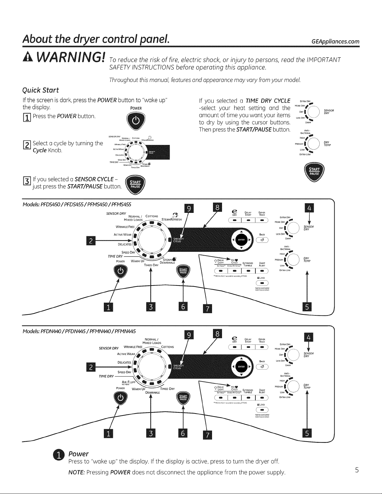
Quick Start
Ifthe screenis dark,pressthe POWERbutton to "woke up"
the disphy. POWER
[_] Pressthe POWERbutton.
SENSORORVNORMA_/COTTO_Sr_A_/S_+j
r_ Selectu cycle byturning the
Cycle Knob.
T,MEOD_
F_lf you selecteda SENSORCYCLE-
just pressthe START/PAUSEbutton.
Models: PFDS450 / PFDS455 / PFMS450 / PFMS455
SENSOR DRY
NORMAL/ COTTONS _
MINED LOADS STEAMRE'FRESH
WRINKLE FREE
ACTIVEWEAR
DEUCATES
SPEEDDRY
POWER WARM U_ OEWR_NKLE
TSMED DRY
If you selected o TIME DRY CYCLE .......
-select your heat setting and the
amount of time you want your items
to dry by using the cursor buttons, oA.,
Then pressthe START/PAUSEbutton.
A_E-
BACTERIAL
......I/ _ oRYTEHP
Low%_J
EXT_LOW
_XTRAORV
BACrEmAL
A_l- /
...... '} TEHP I
SENSOR
DRY
Models: PFDN440 / PFDN445 / PFMN440 / PFMN445
SENSOR DRY WRJNKLE FREE COTTONS
ACTIVE WEAR
DELICATES
SPEEODRY
Po we r
Pressto "woke up" the display. Ifthe display is active, press to turn the dryer off.
NOTE: Pressing POWERdoes not disconnect the appliance from the power supply.
NORMAL /
M{×EO LOADS
WARM UP TIMED DRY
DEWRiNRLE
DELAy O_VER
START RACK
_XTRADRY _
LE v
DAMP
Am_-
BACrEmAL
......|/ ) oRYTEHP
_XTRALOW
About the dryer control panel.
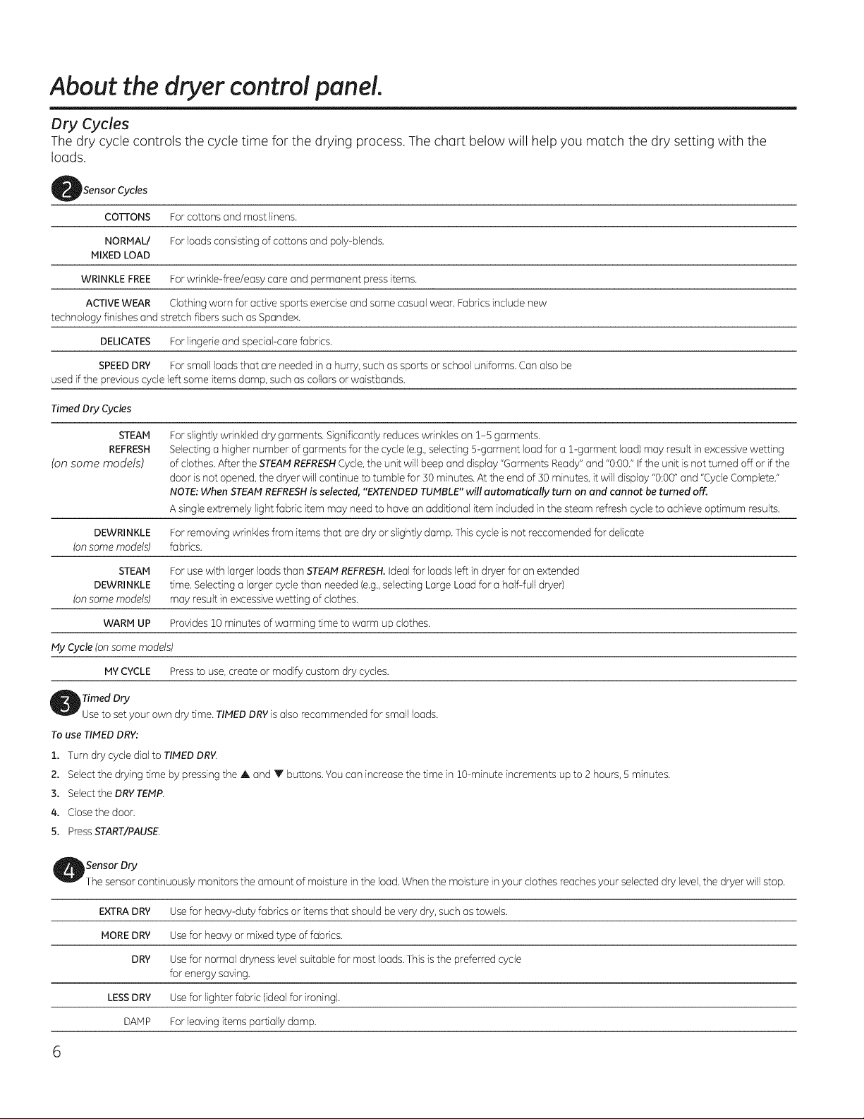
Dry Cycles
The dry cycle controls the cycle time for the drying process. The chart below will help you match the dry setting with the
loads.
iSensor Cycles
COTTONS For cottons and most linens.
NORMAL/ Forloads consisting of cottons and poly-blends.
MIXED LOAD
WRINKLEFREE For wrinkle-free/easy care and permanent press items.
ACTIVEWEAR Clothing worn for active sports exercise and some casual wear. Fabricsinclude new
technology finishes and stretch fibers such as Spandex.
DELICATES For lingerie and spedaFcare fabrics.
SPEEDDRY Forsmall loads that are needed ina hurry, such assports or school uniforms. Can also be
used if the previous cycle left some items damp, such ascollars or waistbands.
Timed Dry Cycles
STEAM
REFRESH
(on some models)
DEWRINKLE Forremoving wrinkles from items that are dry or slightly damp. This cycle is not reccomended for delicate
(onsome models) fabrics.
STEAM For use with larger loads than STEAMREFRESH.Ideal for loads left in dryer for an extended
DEWRINKLE time. Selectinga larger cycle than needed (e.g.,selecting Large Load for a half-full dryer)
(onsome models) may result in excessivewetting of clothes.
WARM UP Provides10 minutes of warming time to warm up clothes.
My Cycle (onsome models)
MYCYCLE Press to use, create or modify custom dry cycles.
Timed Dry
Use to setyour own dry time. TIMEDDRYis also recommended for small loads.
To use TIMED DRY:
l. Turn dry cycle dial to TIMEDDRY
2. Select the drying time by pressing the A and Y buttons. You can increase the time in 10-minute increments up to 2 hours, 5 minutes.
3. Select the DRYTEMP.
4. CIosethe door.
5. Press START/PAUSE.
For slightly wrinkled dry garments. Significantly reduces wrinkles on 1-S garments.
Selecting a higher number of garments for the cycle (e.g.,selecting S-garment load for a 1-garment load) may result in excessive wetting
of clothes. After the STEAMREFRESHCycle,the unit will beep and display "Garments Ready" and "0:00."Ifthe unit is not turned off orif the
door isnot opened, the dryer will continue to tumble for 30 minutes. At the end of 30 minutes, it will display "0:00"and "CycleComplete."
NOTE:When STEAMREFRESHis selected, "EXTENDEDTUMBLE" will automatically turn on and cannot be turned off.
Asingle extremely light fabric item may need to have an additional item included in the steam refresh cycle to achieve optimum results.
,Sensor Dry
Thesensor continuously monitors the amount of moisture in the load.When the moisture in your clothes reaches your selected dry level,the dryer will stop.
EXTRADRY Use for heavy-duty fabrics or items that should be verydry,such as towels.
MOREDRY Usefor heavy or mixed type of fabrics.
DRY Usefor normal dryness level suitable for most loads.Thisis the preferred cycle
for energy saving.
LESSDRY Use for lighter fabric (ideal for ironing).
DAMP For leaving items partially damp.
6
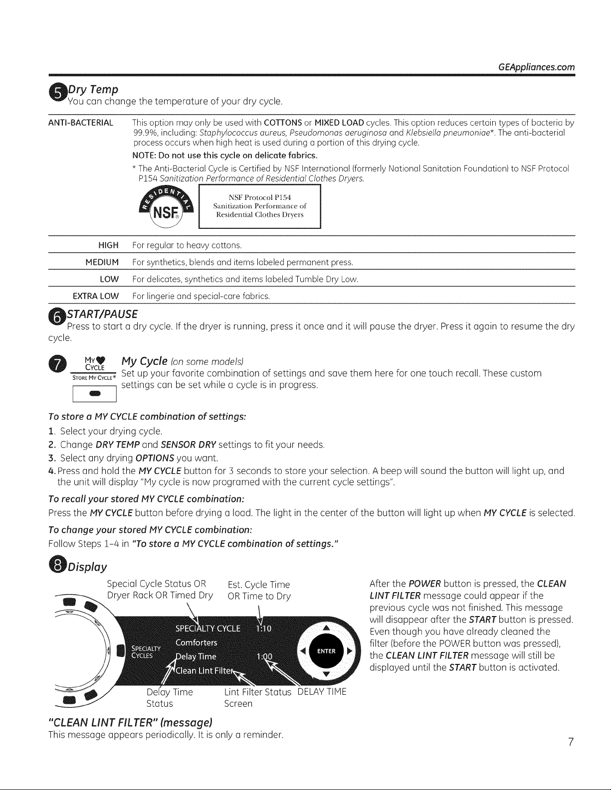
tDry Tamp
¢ou can change the temperature of your dry cycle.
GEAppliances.com
ANTI-BACTERIAL
HIGH For regular to heavy cottons.
MEDIUM For synthetics, blends and items labeled permanent press.
LOW For delicates, synthetics and items labeled Tumble Dry Low.
EXTRALOW For lingerie and special-care fabrics.
This option may only be used with COTTONS or MIXED LOAD cycles. This option reduces certain types of bacteria by
99.9%, including: Staphylococcus oureus, Pseudomonas aeruginosa and Ktebsiella pneumoniae*. The anti-bacterial
process occurs when high heat is used during a portion of this drying cycle.
NOTE: Do not use this cycle on delicate fabrics.
* The Anti-Bacterial Cycle is Certified by NSFInternational (formerly National Sanitation Foundation) to NSFProtocol
P!54 Sanitization Performance of Residential Clothes Dryers.
NSF Protocol P154
Sanitization Periormance of
Residential Clothes Dryers
START/PAUSE
Press to start a dry cycle. If the dryer is running, press it once and it will pause the dryer. Press it again to resume the dry
cycle.
Mv_ My Cycle (onsomemodels)
YCLE
S*o._MvCvcLE*Set up your favorite combination of settings and save them here for one touch recall. These custom
settings can be set while a cycle is in progress.
To store a NY CYCLE combination of settings:
1. Select your drying cycle.
2. Change DRY TEMP and SENSOR DRY settings to fit your needs.
21.Select any drying OPTIONS you want.
4. Press and hold the MY CYCLE button for 5 seconds to store your selection. A beep will sound the button will light up, and
the unit will display "Hy cycle is now programed with the current cycle settings".
To recall your stored NY CYCLE combination:
Press the NY CYCLE button before drying a load. The light in the center of the button will light up when MY CYCLE is selected.
To change your stored MY CYCLE combination:
Follow Steps 1-4 in "To store a MY CYCLE combination of settings."
ODisplay
Special Cycle Status OR Est. Cycle Time
g Dryer Rack OR Timed Dry OR Time to Dry
Del ]y Time Lint Filter Status DELAYTIME
Status Screen
After the POWERbutton is pressed, the CLEAN
LINT FILTERmessage could appear if the
previous cycle was not finished. This message
will disappear after the STARTbutton is pressed.
Eventhough you have already cleaned the
filter (before the POWERbutton was pressed),
the CLEAN LINT FILTERmessage will still be
displayed until the STARTbutton is activated.
"CLEAN LINT FILTER" (message)
This message appears periodically. It is only a reminder.
About the dryer control panel.
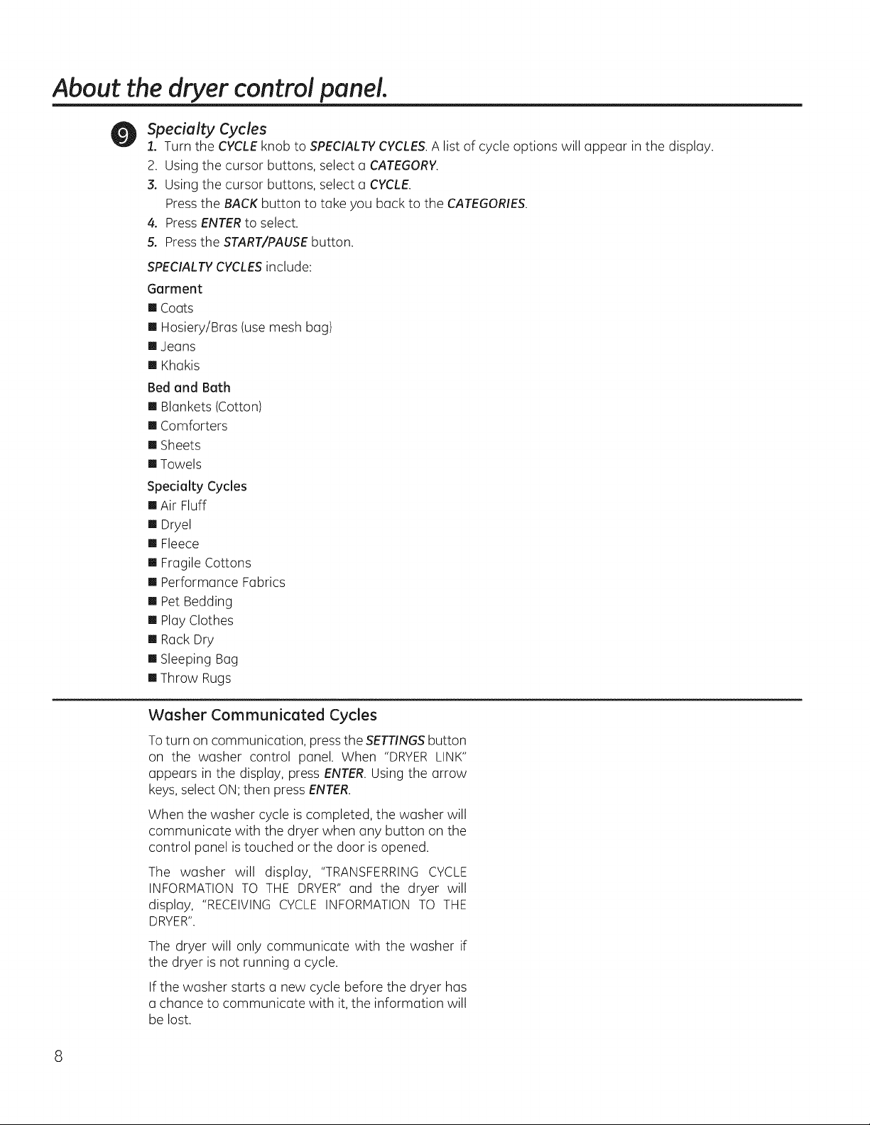
Specialty Cycles
1. Turn the CYCLEknob to SPECIALTYCYCLES.A list of cycle options will appear in the display.
2. Using the cursor buttons, select a CATEGORY.
3. Using the cursor buttons, select a CYCLE.
Pressthe BACK button to take you back to the CATEGORIES.
4. PressENTERto select.
5. Press the START/PAUSEbutton.
SPECIALTYCYCLESinclude:
Garment
[] Coats
[] Hosiery/Bras (use mesh bag)
[] Jeans
[] Khakis
Bed and Bath
[] Blankets (Cotton)
[] Comforters
[] Sheets
[] Towels
Specialty Cycles
[] Air Fluff
[] Dryel
[] Fleece
[] Fragile Cottons
[] Performance Fabrics
[] Pet Bedding
[] Play Clothes
[] Rack Dry
[] Sleeping Bag
[] Throw Rugs
Washer Communicated Cycles
Toturn on communication, pressthe SETTINGSbutton
on the washer control panel. When "DRYERLINK"
appears in the display, press ENTER.Using the arrow
keys,select ON;then press ENTER.
When the washer cycle is completed, the washer will
communicate with the dryer when any button on the
control panel is touched or the door is opened.
The washer will display, "TRANSFERRINGCYCLE
INFORMATION TO THE DRYER"and the dryer will
display, "RECEIVINGCYCLE INFORMATION TO THE
DRYER".
The dryer will only communicate with the washer if
the dryer is not running a cycle.
If the washer starts a new cycle before the dryer has
a chance to communicate with it, the information will
be lost.
About cycle options.
NOTE: Not all features are available on all dryer models. GEAppliances.com
EXTENDED
TUMBLE
O
DAMP
ALERT
'01 DRUM
LIGHT
SETTINGS ÷
(
O
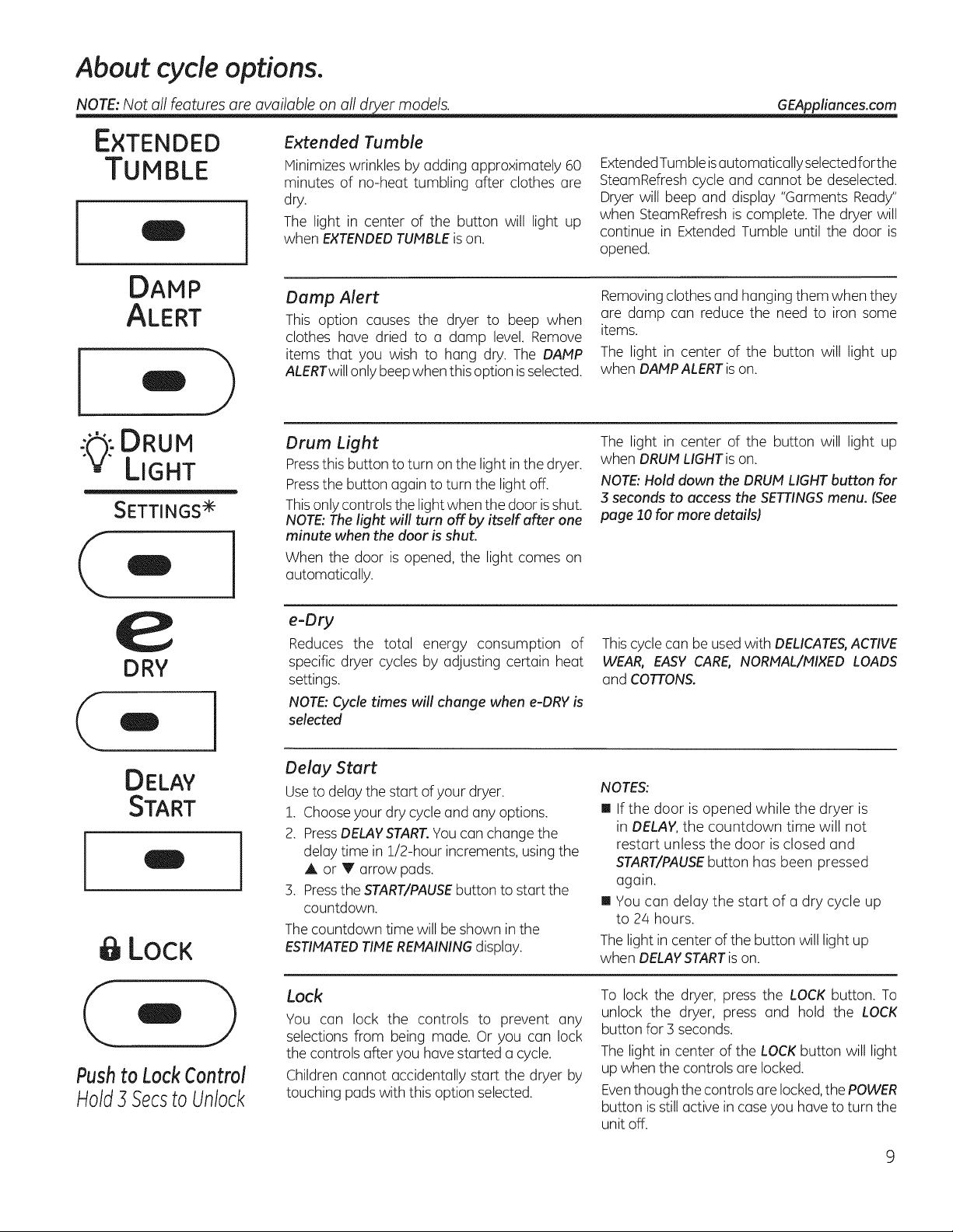
Extended Tumble
Hinimizes wrinkles by adding approximately 60
minutes of no-heat tumbling after clothes are
dry.
The light in center of the button will light up
when EXTENDEDTUMBLEison.
Damp Alert
This option causes the dryer to beep when
clothes have dried to a damp level. Remove
items that you wish to hang dry. The DAMP
ALERTwillonly beepwhen this option is selected.
Drum Light
Pressthis button to turn on the light in the dryer.
Pressthe button again to turn the light off.
Thisonlycontrols the light when the door isshut.
NOTE:The light will turn offby itself after one
minute when the door is shut.
When the door is opened, the light comes on
automatically.
ExtendedTumble isautomatically selectedforthe
SteamRefreshcycle and cannot be deselected.
Dryer will beep and display "Garments Ready"
when SteamRefresh is complete. The dryer will
continue in Extended Tumble until the door is
opened.
Removingclothesand hanging them when they
are damp can reduce the need to iron some
items.
The light in center of the button will light up
when DAHP ALERTison.
The light in center of the button will light up
when DRUMLIGHT is on.
NOTE:Hold down the DRUM LIGHTbutton for
3 seconds to access the SETTINGSmenu. (See
page 10 for more details)
e
DRY
- I
DELAY
START
O
LOCK
Pushto LockControl
Hold3SecstoUnlock
e-Dry
Reduces the total energy consumption of
specific dryer cycles by adjusting certain heat
settings.
NOTE:Cycle times will change when e-DRYis
selected
Delay Start
Useto delay the start of your dryer.
1. Chooseyour dry cycleand any options.
2. PressDELAYSTART.Youcan change the
delay time in 1/2-hour increments, using the
or V arrow pads.
3. Pressthe START/PAUSEbutton to start the
countdown.
Thecountdown time will be shown in the
ESTIMATEDTIMEREMAININGdisplay.
Lock
You can lock the controls to prevent any
selections from being made. Or you can lock
the controls after you have started a cycle.
Children cannot accidentally start the dryer by
touching padswith this option selected.
This cycle can be used with DELICATE& ACTIVE
WEAR, EASY CARE, NORtfAL/HIXED LOADS
and COTTONS.
NOTES:
[] If the door is opened while the dryer is
in DELAY,the countdown time will not
restart unless the door is closed and
START/PAUSEbutton has been pressed
again.
[] You can delay the start of a dry cycle up
to 2/4hours.
Thelight in center of the button will light up
when DELAYSTARTison.
To lock the dryer, press the LOCK button. To
unlock the dryer, press and hold the LOCK
button for 3 seconds.
The light in center of the LOCKbutton will light
up when the controls are locked.
Eventhough the controls are locked,the POWER
button isstill active in caseyou have to turn the
unit off.
About cycleoptions.
NOTE: Not all features are available on all dryer models.
Settings
.Lg:-DRUM
LIGHT
SETTINGS ÷
Under the
adjust the
the display.
VOLUME
SETTINGS option, you can
volume or the brightness of
DISPLAY BRIGHTNESS can be set from HIGH,
HED or LOW.
After you have made your selection, press
ENTER.
[] End of Cycle (signal) volume can be set from
(
Press & hold for 3
seconds for secondary
options
HIGH, MED, LOW or OFF.
[] Control Sounds volume can be set from
HIGH, MED, LOW or OFF.
About dryer features.
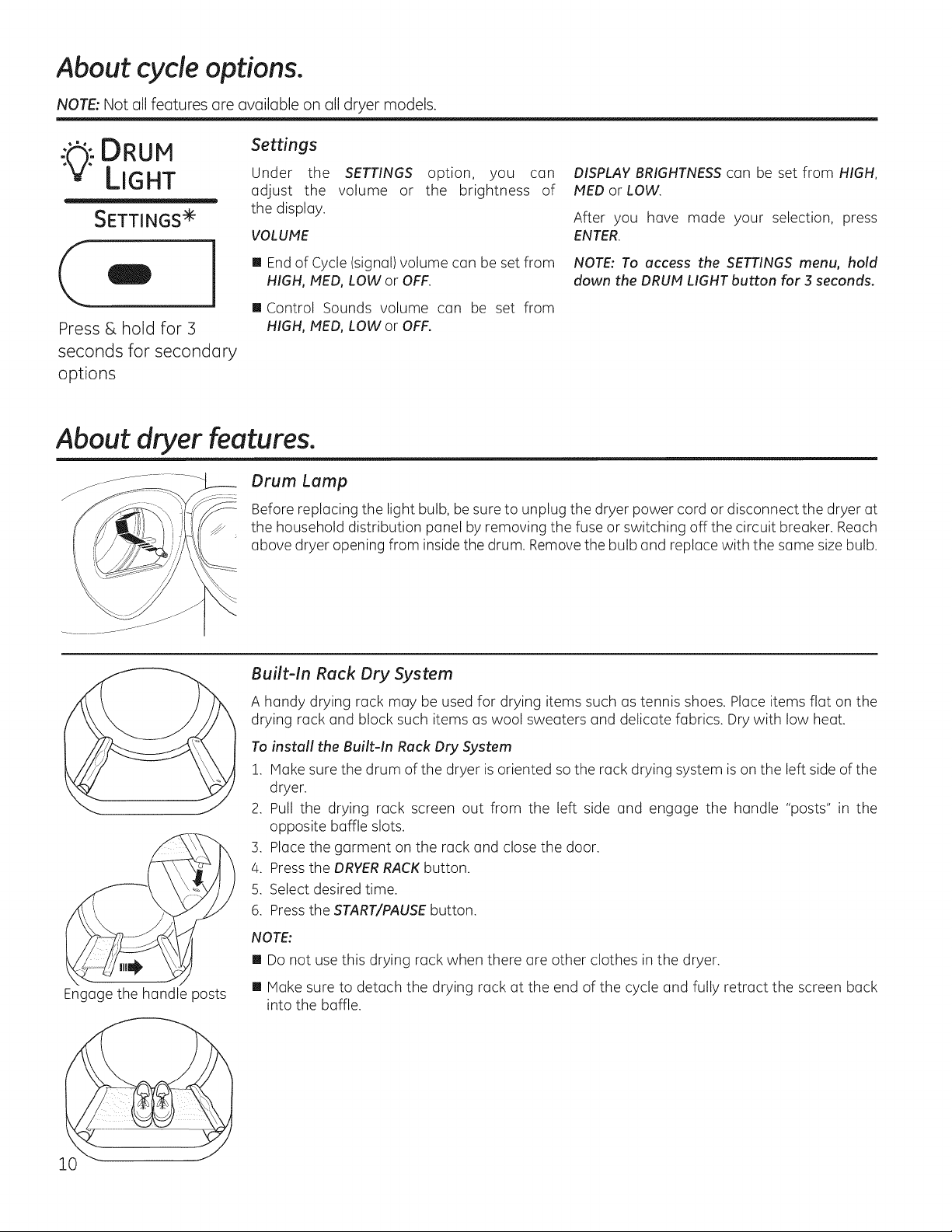
Drum Lump
Before replacing the light bulb, be sure to unplug the dryer power cord or disconnect the dryer at
the household distribution panel by removing the fuse or switching off the circuit breaker. Reach
above dryer opening from inside the drum. Removethe bulb and replace with the same size bulb.
Built-In Rack Dry System
A handy drying rack may be used for drying items such as tennis shoes. Place items flat on the
drying rack and block such items as wool sweaters and delicate fabrics. Dry with low heat.
Toinstall the Built-In Rack Dry System
1. Hake sure the drum of the dryer is oriented so the rack drying system is on the left side of the
dryer.
2. Pull the drying rack screen out from the left side and engage the handle "posts" in the
opposite baffle slots.
3. Place the garment on the rack and close the door.
4. Pressthe DRYERRACKbutton.
5. Select desired time.
6. Pressthe START/PAUSEbutton.
NOTE:
[] Do not use this drying rack when there are other clothes in the dryer.
NOTE: To access the SETTINGS menu, hold
down the DRUM LIGHT button for 3 seconds.
Engage the handle posts
[] Hake sure to detach the drying rack at the end of the cycle and fully retract the screen back
into the baffle.
About d er features (cont.). GEAppliances.com
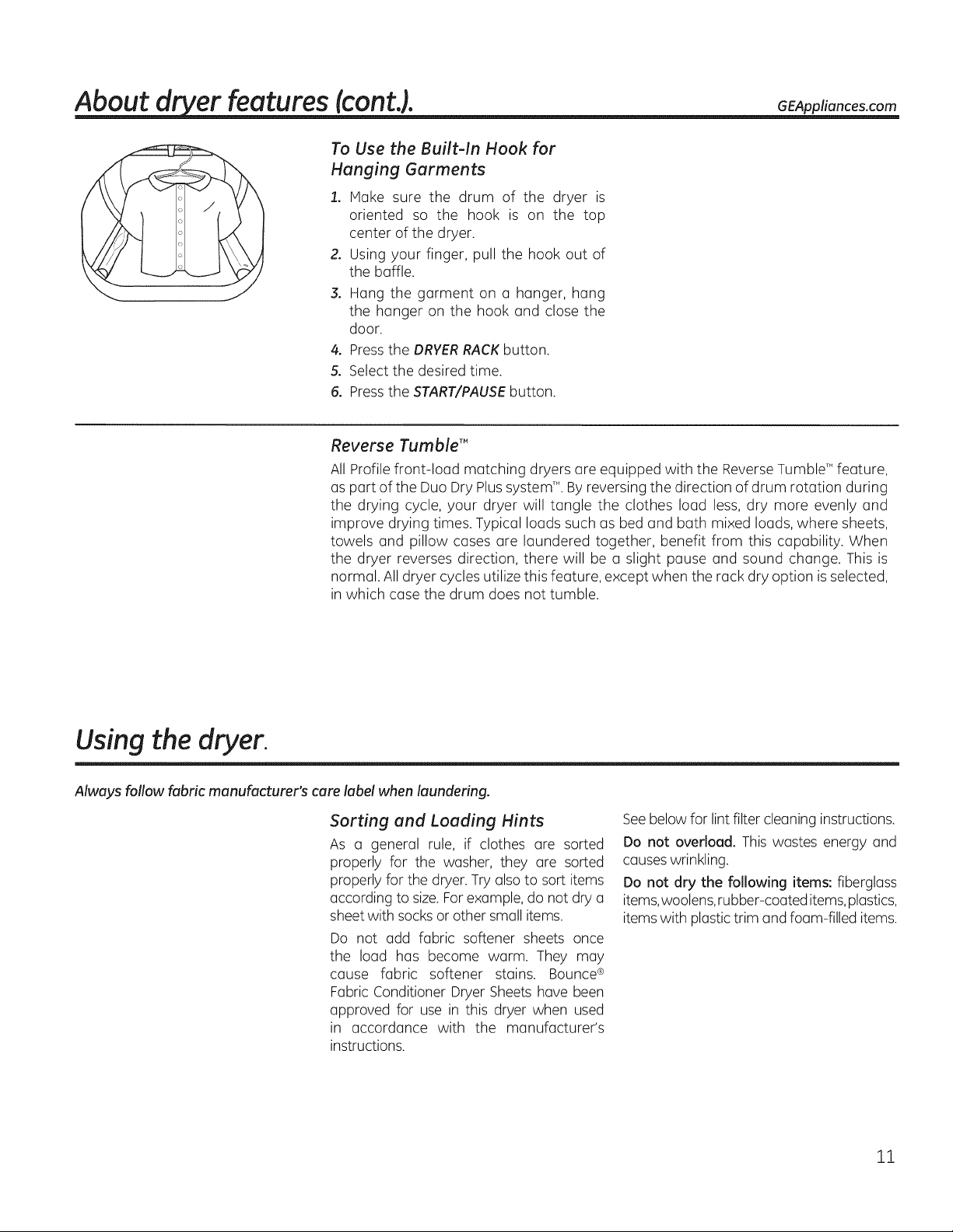
To Use the Built-In Hook for
Hanging Garments
1. Make sure the drum of the dryer is
oriented so the hook is on the top
center of the dryer.
2. Using your finger, pull the hook out of
the baffle.
3. Hang the garment on a hanger, hang
the hanger on the hook and close the
door.
4. Pressthe DRYERRACKbutton.
5. Select the desired time.
6. Press the START/PAUSE button.
Reverse Tumble'"
AllProfile front-loud matching dryers are equipped with the Reverse mumbW" feature,
as part of the Duo Dry Plus system'L By reversing the direction of drum rotation during
the drying cycle, your dryer will tangle the clothes loud less, dry more evenly and
improve drying times. Typical loads such as bed and bath mixed loads, where sheets,
towels and pillow cases are laundered together, benefit from this capability. When
the dryer reverses direction, there will be a slight pause and sound change. This is
normal. Alldryer cycles utilize this feature, except when the rack dry option is selected,
in which case the drum does not tumble.
Using the dryer.
Always follow fabric manufacturer's care label when laundering.
Sorting and Loading Hints
As u general rule, if clothes are sorted
properly for the washer, they are sorted
properly for the dryer. Try also to sort items
according to size. For example, do not dry a
sheet with socks or other small items.
Do not add fabric softener sheets once
the load has become warm. They may
cause fabric softener stains. Bounce ®
Fabric Conditioner Dryer Sheets have been
approved for use in this dryer when used
in accordance with the manufacturer's
instructions.
Seebelow for lint filter cleaning instructions.
Do not overload. This wastes energy and
causeswrinkling.
Do not dry the following items: fiberglass
items,woolens,rubber-coated items,plastics,
items with plastictrim and foam-filled items.
11

Using the dryer.
Fabric Care Labels
Below are fabric care label "symbols" that affect the clothing you willbe laundering.
Wash Labels
cycle No_molP............tP,es_/ Ge,,tl_'_/ Do,,otwo_h Do,,otw,i,,g
Front load Target
target water Category Water Temperature
temperature Co_d 27°C/80°F
wrinkle resistant delicate Hand wash
Tap Cold Inlet Water Temperature
Warm 40°C/105°F
Hot 50°C/120°F
Sanitize 70°C/160°F
Automatic
Temperature Control
Not used
Used
Used
Used
Used
Dry Labels
dry
Dry Normal Permanent Press/
wrinkle resistant
bq
Gentle/
delicate
.eat ® ®
setting
High Medium Low No heat/air
nPsetCiu°cltions
Line dry/ Drip dry Dry fiat In the shade
hang to dry
Bleach Labels
Do not tumble dry
Do not dry
(used with
do not wash)
12
Bleach £ £
symbols AnybJeGch Only ...... hlorine bleach Do not bleach
(when needed) (when needed)
Care and Cleaning of the Dryer
Dryer Interior end Duct: The interior of
the appliance and exhaust duct should be
cleaned once a year by qualified service
personnel.
The Exterior: Wipe or dust any spills or
washing compounds with a damp cloth.
Dryer control panel and finishes may be
damaged by some laundry pretreatment
soil and stain remover products. Apply these
products away from the dryer. The fabric
may then be washed and dried normally.
Damage to your dryer caused by these
products is not covered by your warranty.
Do not touch the surface or the display with
sharp objects.
The Lint Filter: Clean the lint filter before
each use. Remove by pulling straight up.
Run your fingers across the filter. A waxy
buildup may form on the lint filter from
using dryer-added fabric softener sheets.
To remove this buildup, wash the lint screen
in warm, soapy water. Dry thoroughly and
replace. Donot operate the dryer without the
lint filter in place.
Vacuum the lint from the dryer lint filter if you
notice a change in dryer performance.
Stainless Steel: To clean stainless steel
surfaces, use a damp cloth with a mild,
nonabrasive cleaner suitable for stainless
steel surfaces. Remove the cleaner residue,
and then dry with a clean cloth.
Thestainlesssteel used to make the dryer drum
provides the highest reliabilityavailable in a GE
dryer. If the dryer drum should be scratched or
dented during normal use,the drum will not rust
or corrode.Thesesurfaceblemisheswillnot affect
thefunction or durabilityofthe drum.
The Exhaust Hood: Check with a mirror that
the inside flaps of the hood move freely
when operating. Make sure that there is no
wildlife (birds, insects, etc.) nesting inside the
duct or hood.
SMART APPLIANCE tonsome models) GEAppliances.com
ModelsPFDS450,PFDS455,PFDN440,PFDN4V45orecompatiblewiththe
GESmartApplianceModule(SAM)whichconbepurchasedseparately.
Contactyourlocalutilityorvisitwww.GEApplionces.com/smort-opplionces
toseeifyourareaisusingDemandResponse(DR)technology.
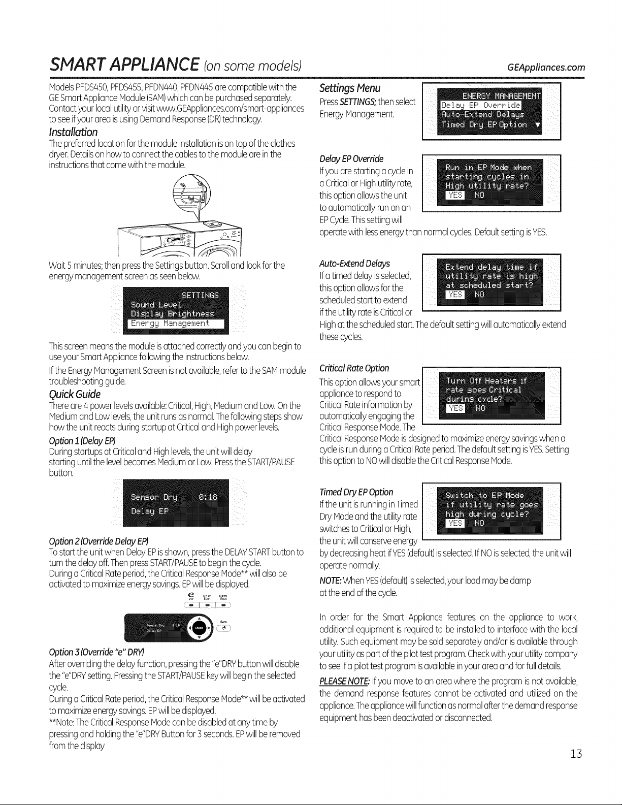
Installation
Thepreferredlocationforthemoduleinstallationisontop oftheclothes
dryer.Detailsonhowtoconnectthecablestothemoduleareinthe
instructionsthatcomewiththemodule.
Wait5minutes;thenpresstheSettingsbutton.Scrollandlookforthe
energymanagementscreenasseenbelow.
Thisscreenmeansthemoduleisattachedcorrectlyandyouconbeginto
useyourSmartAppliancefollowingtheinstructionsbelow.
tftheEnergyManagementScreenisnotavailable,refertotheSAMmodule
troubleshootingguide.
Quick Guide
Thereore4powerlevelsavailable:Critical,High,MediumandLow.Onthe
MediumandLowlevels,theunitrunsasnormal.Thefollowingstepsshow
howtheunitreactsduringstortupatCriticalandHighpowerlevels.
Option1(DelayEP)
DuringstortupsatCriticalandHighlevels,theunitwilldelay
startinguntilthelevelbecomesMediumorLow.PresstheSTART/PAUSE
button.
PressSETTINGS;thenselect
EnergyManagement.
Settings Nenu r
DelayEPOverride
tfyouorestartingocyclein
oCriticalorHighutilityrate,
thisoptionallowstheunit
toautomaticallyrunonon
EPCycle.Thissettingwill
operatewithlessenergythannormalcycles.DefaultsettingisYES.
tfatimeddelayisselected,
thisoptionallowsforthe
Auto-ExtendDelays
scheduledstarttoextend
ifthe utilityrateisCriticalor
Highatthescheduledstart.Thedefaultsettingwillautomaticallyextend
thesecycles.
CriticalRateOption
Thisoptionallowsyoursmart
appliancetorespondto
CriticalRateinformationby
automaticallyengagingthe
CriticalResponseMode.The
CriticalResponseModeisdesignedtomaximizeenergysavingswhena
cycleisrunduringaCriticalRateperiod.ThedefaultsettingisYES.Setting
thisoptiontoNOwilldisablethe CriticalResponseMode.
Option2(OverrideDelayEPJ
TostarttheunitwhenDelayEPisshown,presstheDELAYSTARTbuttonto
turnthedelayoff.ThenpressSTART/PAUSEto beginthecycle.
DuringaCriticalRateperiod,theCriticalResponseMode**willalsobe
activatedto maximizeenergysavings.EPwillbedisplayed.
Option3(Override"e"DRY}
Afteroverridingthedelayfunction,pressingthe"e"DRYbuttonwilldisable
the"e"DRYsetting.PressingtheSTART/PAUSEkeywillbeginthe selected
cycle.
DuringoCriticalRateperiod,theCriticalResponseMode**willbeactivated
tomaximizeenergysavings.EPwillbedisplayed.
**Note:TheCriticalResponseModeconbedisabledat anytimeby
pressingandholdingthe"e"DRYButtonfor5seconds.EPwillberemoved
fromthedisplay
tftheunitisrunninginTimedDryModeandtheutilityrate
TimedDryEPOption
switchestoCriticalorHigh,
theunitwillconserveenergy
bydecreasingheatifYES(default)isselected,tfNOisselected,the unitwill
operatenormally.
NOTE:WhenYES(default)isselected,yourloadmaybedamp
atthe endofthecycle.
tn orderfor the SmartAppliancefeatureson the applianceto work,
additionalequipmentisrequiredto be installedto interfacewiththelocal
utility.Suchequipmentmaybesoldseparatelyand/orisavailablethrough
yourutilityaspartofthepilottestprogram.Checkwithyourutilitycompany
toseeifapilottestprogramisavailableinyourareaandforfulldetails.
PLEASENOTE:tfyou movetoan areawheretheprogramisnotavailable,
the demandresponsefeaturescannotbeactivatedand utilizedon the
appliance.Theappliancewillfunctionasnormalafterthedemandresponse
equipmenthasbeendeactivatedordisconnected.
13
stall ti
I
Dryer
I
structi
Questions? Call 800.GE.CARES {800.432.2737) or visit our Web site at: GEAppliances.com
In Canada, call 1.800.561.3344 or visit www.GEAppliances.ca
ns
BEFORE YOU BEGIN
Readthese instructions completely and carefully.
• IMPORTANT- Savethese instructions for local
electrical inspector's use.
• IHPORTANT-Observeallgoverning codesand
ordinances.
• Installthe clothes dryer according to the manufacturer's
instructions and local codes.
• Note to Installer - Be sure to leave these instructions
with the Consumer.
• Note to Consumer - Keepthese instructions for future
reference.
• Clothes dryer installation must be performed by a
qualified installer.
• Thisdryer must be exhausted to the outdoors.
° Beforethe old dryer is removed from service or
discarded, remove the dryer door.
° Service information and the wiring diagram are located
in the control console.
° Donot allow children on or in the appliance. Close
supervision of children isnecessary when the appliance
is used near children.
° Proper installation isthe responsibility of the installer.
• Product failure due to improper installation is not
covered under the Warranty.
• Install the dryer where the temperature is above 50°F
for satisfactory operation of the dryer control system.
° Removeand discard existing plastic or metal foil duct
and replace with UL-listed duct.
CALIFORNIA SAFE DRINKING WATER AND
TOXIC ENFORCEMENT ACT
This act requires the governor of California to publish a
list of substances known to the state to cause cancer,
birth defects or other reproductive harm and requires
businessesto warn customers of potential exposureto such
substances. Gas appliances can cause minor exposure to
four ofthese substances,namely benzene,carbon monoxide,
formaldehyde and soot, caused primarily by the incomplete
combustion of natural gas or LP fuels. Properly adjusted
dryers will minimize incomplete combustion. Exposure to
these substances can be minimized further by properly
venting the dryerto the outdoors.
PFDS450 / PFDS455/PFDN440 / PFDN445 /
PFMS450 / PFMS455 / PFMN440 / PFMN445
i
FOR YOUR SAFETY:
I G -- Risk of Fire
• To reduce the risk of severe injury or death, follow all
installation instructions.
• Clothes dryer installation must be performed by a
qualified installer.
Install the clothes dryer according to these
instructions and in accordance with local codes.
This dryer must be exhausted to the outdoors.
Use only rigid metal 4" diameter ductwork inside the
dryer cabinet and use only UL approved transition
ducting between the dryer and the home duct.
DO NOT install a clothes dryer with flexible plastic
ducting materials. If flexible metal (semi-rigid or
foil-type) duct is installed, it must be UL-listed and
installed in accordance with the instructions found
in "Connecting the Dryer to House Vent" on page 26
of this manual. Flexible ducting materials are known
to collapse, be easily crushed and trap lint. These
conditions will obstruct dryer airflow and increase
the risk of fire.
Do not install or store this appliance in any location
where it could be exposed to water and/or weather.
Save these instructions. (Installers: Be sure to leave
these instructions with the customer.)
FOR GAS MODELS ONLY:
NOTE: Installation and service of this dryer must be
performed by a qualified installer, service agency or
the gas supplier.
In the Commonwealth of Massachusetts:
• This product must be installed by a licensed
plumber or gas fitter.
• When using ball-type gas shut-offvalves, they
shall be T-handle-type.
• A flexible gas connector, when used, must not
exceed 3 feet.
14
Installation Instructions
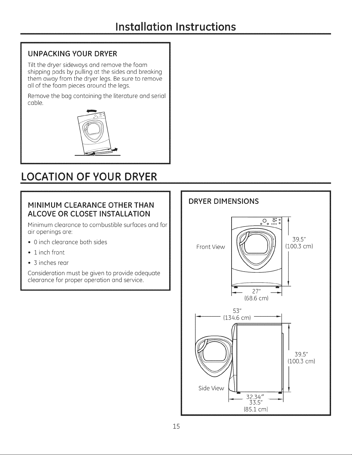
UNPACKING YOUR DRYER
Tilt the dryer sideways and remove the foam
shipping pads by pulling at the sides and breaking
them away from the dryer legs. Be sure to remove
all of the foam pieces around the legs.
Remove the bag containing the literature and serial
cable.
LOCATION OF YOUR DRYER
MINIMUM CLEARANCE OTHER THAN
ALCOVE OR CLOSET INSTALLATION
Minimum clearance to combustible surfaces and for
air openings are:
, 0 inch clearance both sides
, 1 inch front
, 3 inches rear
Consideration must be given to provide adequate
clearance for proper operation and service.
DRYER DIMENSIONS
oOo2!
Front View
27"
(68.6 cm)
53"
I------- 1134.6cm) "
T
39.5"
100.3 cm)
39.5"
(100.3 cm)
15
.!
4-- 32.34"
33.5"
(85.1 cm)
Installation Instructions
REQUIREMENTS FOR ALCOVE OR
CLOSET INSTALLATION
. Your dryer is approved for installation in an
alcove or closet, as stated on a label on the dryer
back.
. The dryer MUST be vented to the outdoors. See
the EXHAUSTING THE DRYERsection.
. Minimum clearance between dryer cabinet and
adjacent walls or other surfaces is:
0" either side
3"frontand rear
. Minimum vertical space from floor to overhead
shelves, cabinets, ceilings, etc., is 52".
. Closet doors must be Iouvered or otherwise
ventilated and have at least 60 square inches
of open area equally distributed. If the closet
contains both a washer and a dryer, doors must
contain a minimum of 120 square inches of open
area equally distributed.
. The closet should be vented to the outdoors to
prevent gas pocketing in case of gas in the supply
line.
. No other fuel-burning appliance shall be installed
in the same closet with the dryer (gas models
only).
NOTE: WHEN THE EXHAUST DUCT IS LOCATED AT
THE REAR OF THE DRYER, MINIMUM CLEARANCE
FROM THE WALL IS5.5 INCHES.
BATHROOM OR BEDROOM INSTALLATION
. The dryer MUST be vented to the outdoors. See
EXHAUSTING THE DRYER.
. The installation must conform with local codes or,
in the absence of local codes, with the NATIONAL
ELECTRICALCODE, ANSI/NFPA NO. 70 (for electric
dryers) or NATIONAL FUEL GAS CODE, ANSI Z223
(for gas dryers).
MOBILE OR MANUFACTURED HOME
INSTALLATION
. The installation must conform to the
MANUFACTURED HOME CONSTRUCTION &
SAFETYSTANDARD, TITLE 24, PART32-80 or, when
such standard is not applicable, with AMERICAN
NATIONAL STANDARD FOR MOBILE HOME, NO.
50lB.
. The dryer MUST be vented to the outdoors with
the termination securely fastened to the mobile
home structure. (See EXHAUSTING THE DRYER.)
. The vent MUST NOT be terminated beneath a
mobile or manufactured home.
. The vent duct material MUST BE METAL.
. FOR GAS MODELS ONLY: KIT 14-D346-33 MUST be
used to attach the dryer securely to the structure.
. FOR GAS MODELS ONLY: The vent MUST NOT be
connected to any other duct, vent or chimney.
. Do not use sheet metal screws or other refastening
devices which extend into the interior of the
exhaust vent.
. Provide an opening with a free area of at least 25
sq. in. for introduction of outside air into the dryer
room.
GARAGE INSTALLATION (IF ALLOWED
BY LOCAL CODES}
. Dryers installed in garages must be elevated 18
inches (46cm) above the floor.
16
Installation Instructions
CONNECTING iNLET HOSES
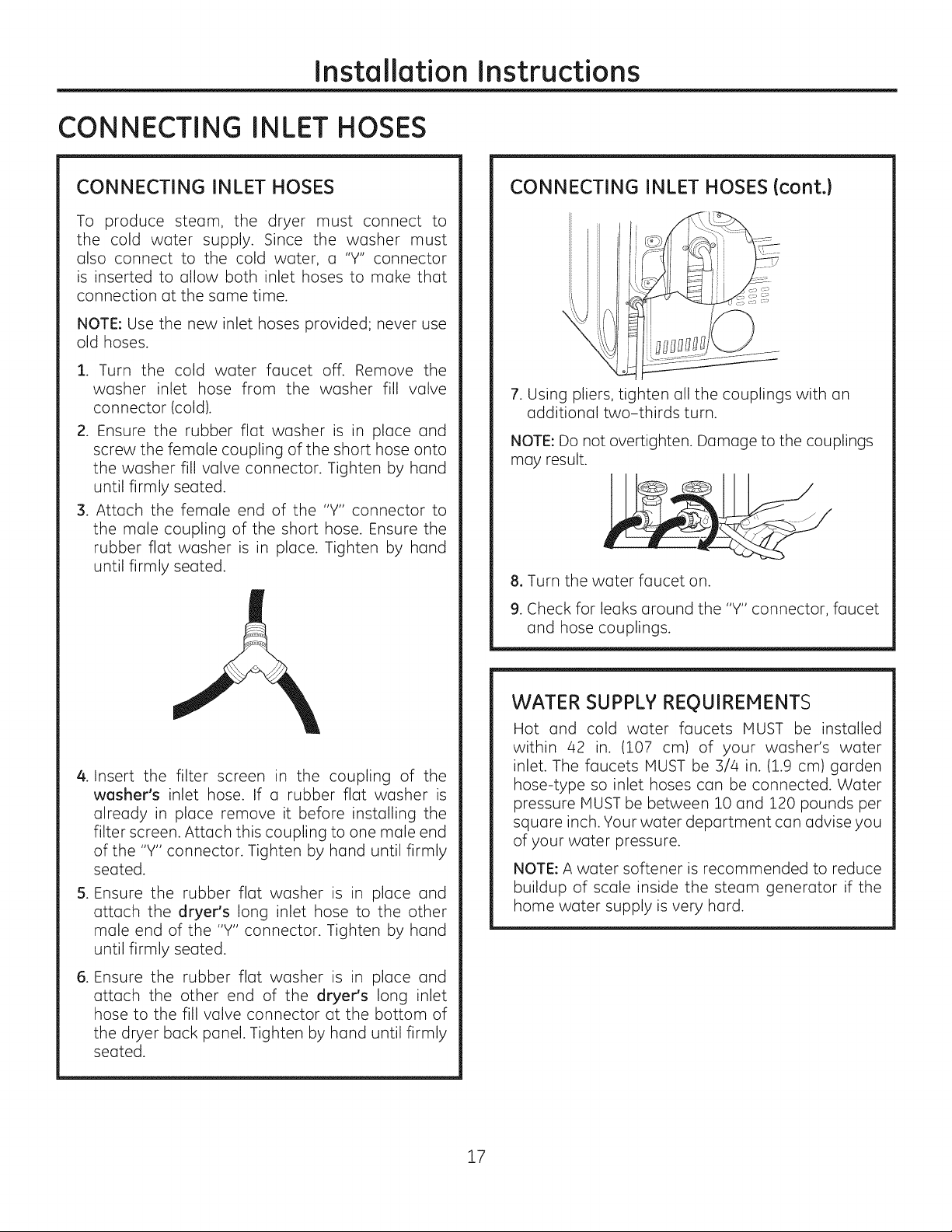
CONNECTING INLET HOSES
To produce steam, the dryer must connect to
the cold water supply. Since the washer must
also connect to the cold water, a "Y" connector
is inserted to allow both inlet hoses to make that
connection at the same time.
NOTE: Use the new inlet hoses provided; never use
old hoses.
1. Turn the cold water faucet off. Remove the
washer inlet hose from the washer fill valve
connector (cold).
2. Ensure the rubber flat washer is in place and
screw the female coupling of the short hose onto
the washer fill valve connector. Tighten by hand
until firmly seated.
3. Attach the female end of the "Y" connector to
the male coupling of the short hose. Ensure the
rubber flat washer is in place. Tighten by hand
until firmly seated.
CONNECTING INLET HOSES (cont.)
J
7. Using pliers, tighten all the couplings with an
additional two-thirds turn.
NOTE: Do not overtighten. Damage to the couplings
may result.
8, Turn the water faucet on.
9. Check for leaks around the "Y" connector, faucet
and hose couplings.
.
Insert the filter screen in the coupling of the
washer's inlet hose. If a rubber flat washer is
already in place remove it before installing the
filter screen. Attach this coupling to one male end
of the "Y" connector. Tighten by hand until firmly
seated.
S.
Ensure the rubber flat washer is in place and
attach the dryer's long inlet hose to the other
male end of the "Y" connector. Tighten by hand
until firmly seated.
.
Ensure the rubber flat washer is in place and
attach the other end of the dryer's long inlet
hose to the fill valve connector at the bottom of
the dryer back panel. Tighten by hand until firmly
seated.
WATER SUPPLY REOUIREMENTS
Hot and cold water faucets MUST be installed
within 42 in. (107 cm) of your washer's water
inlet. The faucets MUST be 3/4 in. (1.9 cm) garden
hose-type so inlet hoses can be connected. Water
pressure MUST be between 10 and 120 pounds per
square inch. Your water department can advise you
of your water pressure.
NOTE: A water softener is recommended to reduce
buildup of scale inside the steam generator if the
home water supply is very hard.
17
Installation Instructions
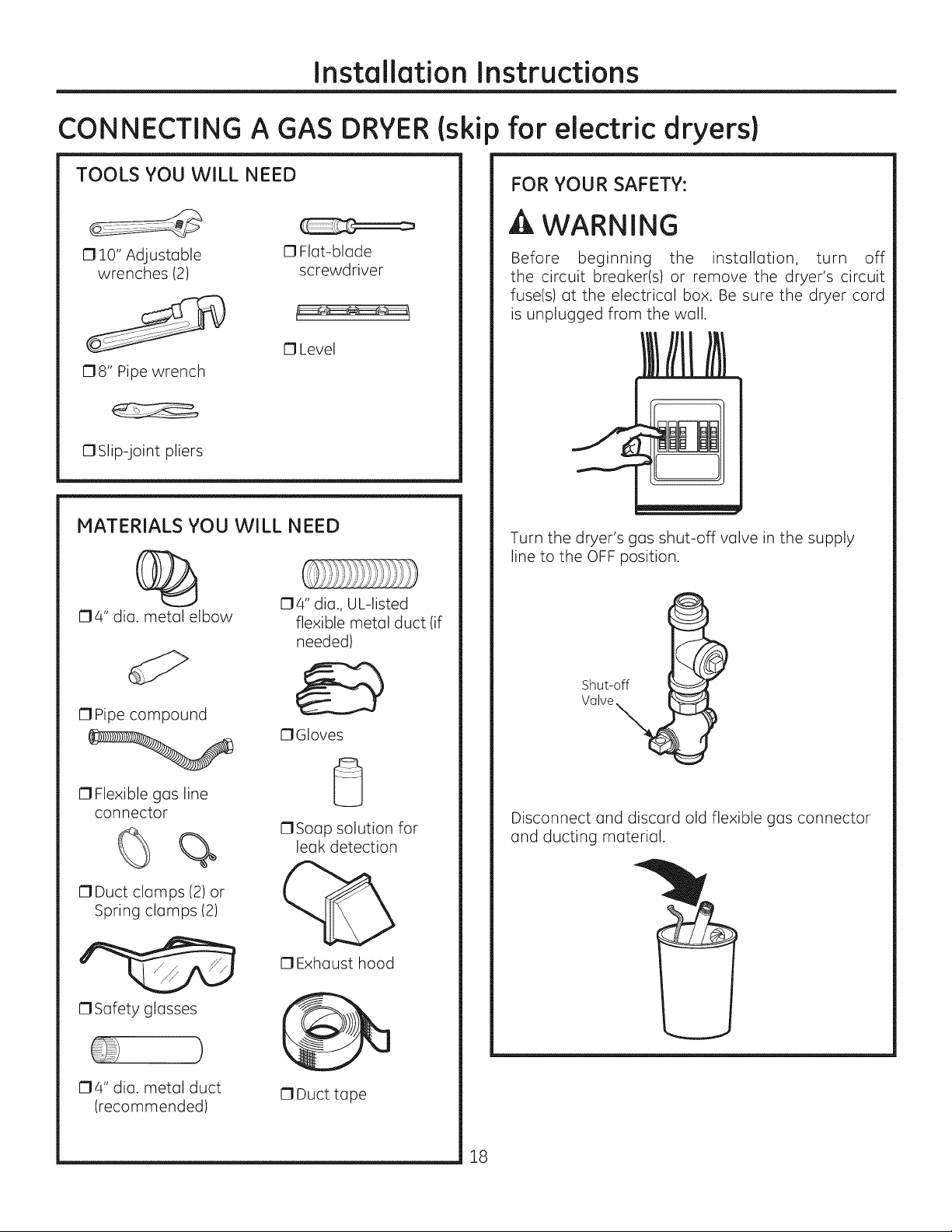
CONNECTING A GAS
TOOLS YOU WILL NEED
1710" Adjustable
wrenches (2)
C18" Pipe wrench
17Slip-joint pliers
MATERIALS YOU WILL NEED
0 Flat-blade
screwdriver
C1Level
DRYER(ski
) for electric dryersl
FOR YOUR SAFETY:
A WARNING
Before beginning the installation, turn off
the circuit breaker(s) or remove the dryer's circuit
fuse(s) at the electrical box. Be sure the dryer cord
is unplugged from the wall.
Turn the dryer's gas shut-off valve in the supply
line to the OFF position.
174" dia. metal elbow
17Pipe compound
17Flexible gas line
connector
%
17Duct clamps (2) or
Spring clamps (2)
17Safety glasses
174" dia., UL-listed
flexible metal duct (if
needed)
17Gloves
C1Soap solution for
leak detection
17Exhaust hood
Shut-off
Valve
Disconnect and discard old flexible gas connector
and ducting material.
174" dia. metal duct
(recommended)
17Duct tape
18
Installation Instructions
GAS REQUIREMENTS
A WARNING
. Installation must conform to local codes and
ordinances, or in their absence, with the National
Fuel Gas Code, ANSI Z223.Z/NFPA 54, or the Natural
Gas and Propane Installation Code, CSA B149.1.
. This gas dryer is equipped with a Valve and
Burner Assembly for use only with natural gas.
Using conversion kit 14-A048, your local service
organization can convert this dryer for use with
propane (LP)gas. ALL CONVERSIONSMUST BEMADE
BY PROPERLYTRAINEDAND QUALIFIED PERSONNEL
AND IN ACCORDANCE WITH LOCAL CODES AND
ORDINANCE REQUIREMENTS.
, The dryer must be disconnected from the gas supply
piping system during any pressure testing of that
system at a test pressure in excess of 0.5 PSI (3.4
KPa).
, The dryer must be isolated from the gas supply
piping system by closing the equipment shut-off
valve during any pressure testing of the gas supply
piping of test pressure equal to or less than 0.5 PSI
(3.4KPa).
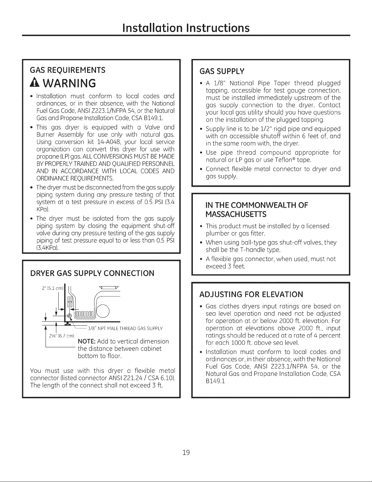
DRYER GAS SUPPLY CONNECTION
GAS SUPPLY
. A 1/8" National Pipe Taper thread plugged
tapping, accessible for test gauge connection,
must be installed immediately upstream of the
gas supply connection to the dryer. Contact
your local gas utility should you have questions
on the installation of the plugged tapping.
. Supply line is to be 1/2" rigid pipe and equipped
with an accessible shutoff within 6 feet of, and
in the same room with, the dryer.
. Use pipe thread compound appropriate for
natural or LP gas or use Teflon ®tape.
, Connect flexible metal connector to dryer and
gas supply.
IN THE COMMONWEALTH OF
MASSACHUSETTS
. This product must be installed by a licensed
plumber or gas fitter.
. When using ball-type gas shut-off valves, they
shall be the T-handle type.
. A flexible gas connector, when used, must not
exceed 3 feet.
2" 15.1 cm)
3/8" NPT MALE THREAD GAS SUPPLY
I 2Yd' (6.7 cm)
You must use with this dryer a flexible metal
connector (listed connector ANSI Z21.24 / CSA 6.10).
The length of the connect shall not exceed 3 ft.
NOTE: Add to vertical dimension
the distance between cabinet
bottom to floor.
ADJUSTING FOR ELEVATION
Gas clothes dryers input ratings are based on
sea level operation and need not be adjusted
for operation at or below 2000 ft. elevation. For
operation at elevations above 2000 ft., input
ratings should be reduced at a rate of a percent
for each 1000 ft. above sea level.
Installation must conform to local codes and
ordinances or, in their absence, with the National
Fuel Gas Code, ANSI Z223.1/NFPA 54, or the
Natural Gas and Propane Installation Code, CSA
B149.1
19
Installation Instructions
CONNECTING A GAS DRYER (cont,)
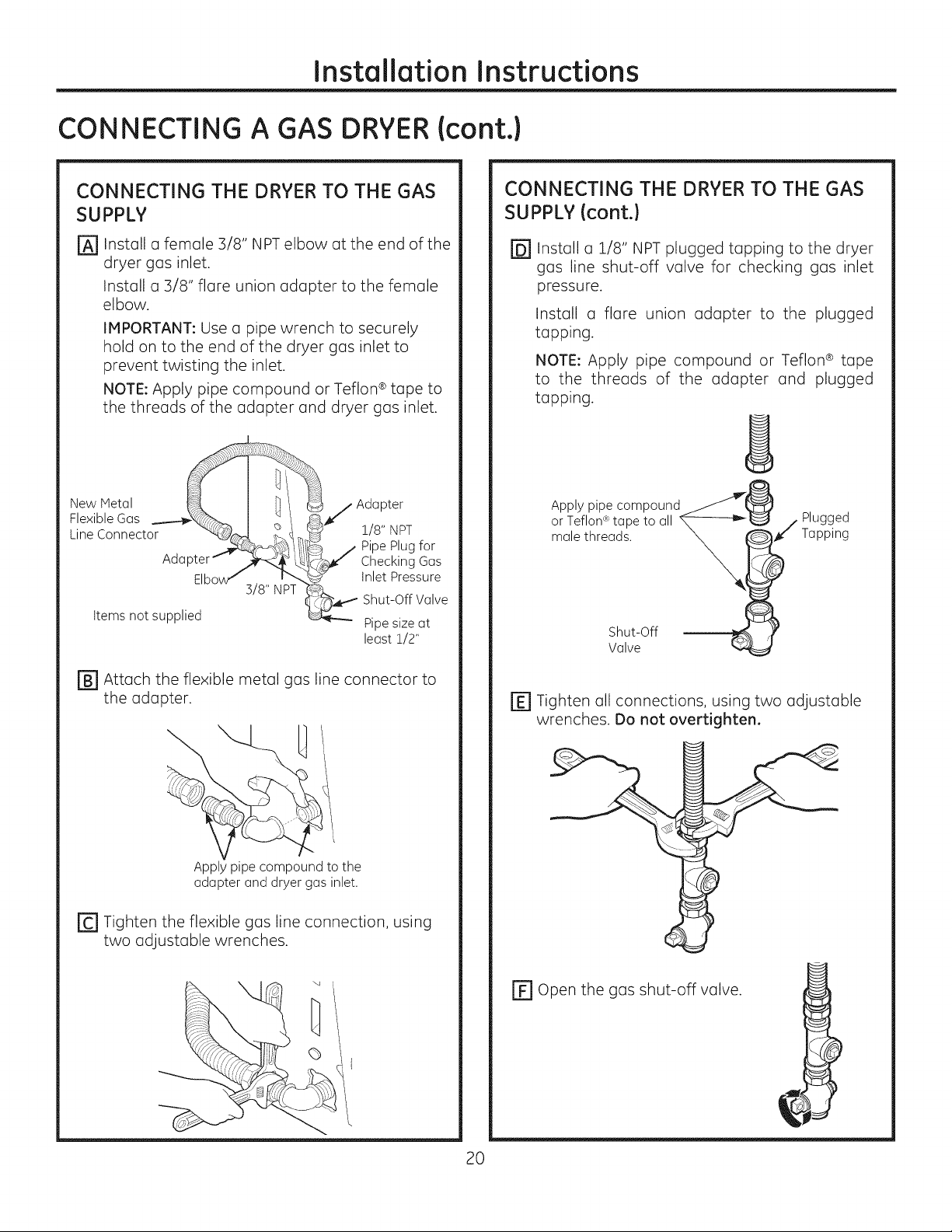
CONNECTING THE DRYER TO THE GAS
SUPPLY
Install a female 3/8" NPTelbow at the end of the
@
dryer gas inlet.
Install a 3/8" flare union adapter to the female
elbow.
IMPORTANT: Use a pipe wrench to securely
hold on to the end of the dryer gas inlet to
prevent twisting the inlet.
NOTE: Apply pipe compound or Teflon ®tape to
the threads of the adapter and dryer gas inlet.
New Metal _¢_
Flexible Gas __...--._x_7_ I &I
Line Connector "*<__,
Adapter"*-" ./_-_ _.
Elbow/ i _.
Items not supplied
3/8" NPT
_/Adapter
_¢" 1/8" NPT
/ Pipe Plug for
]q_ Checking Gas
_ Inlet Pressure
O,, a e
_-'_q_'- Pipe size at
least 1/2"
CONNECTING THE DRYERTO THE GAS
SUPPLY(cont.)
Install a 1/8" NPT plugged tapping to the dryer
@
gas line shut-off valve for checking gas inlet
pressure.
Install a flare union adapter to the plugged
tapping.
NOTE: Apply pipe compound or Teflon ® tape
to the threads of the adapter and plugged
tapping.
Apply pipe compound
or Teflon¢_tape to all
male threads.
Shut-Off
Valve
Plugged
Tapping
rB1 Attach the flexible metal gas line connector to
the adapter.
Apply pipe compound to the
adapter and dryer gas inlet.
rc1 Tighten the flexible gas line connection, using
two adjustable wrenches.
x,,
• -.q
r_ Tighten all connections, using two adjustable
wrenches. Do not overtighten.
[] Open the gas shut-off valve.
20
Installation Instructions
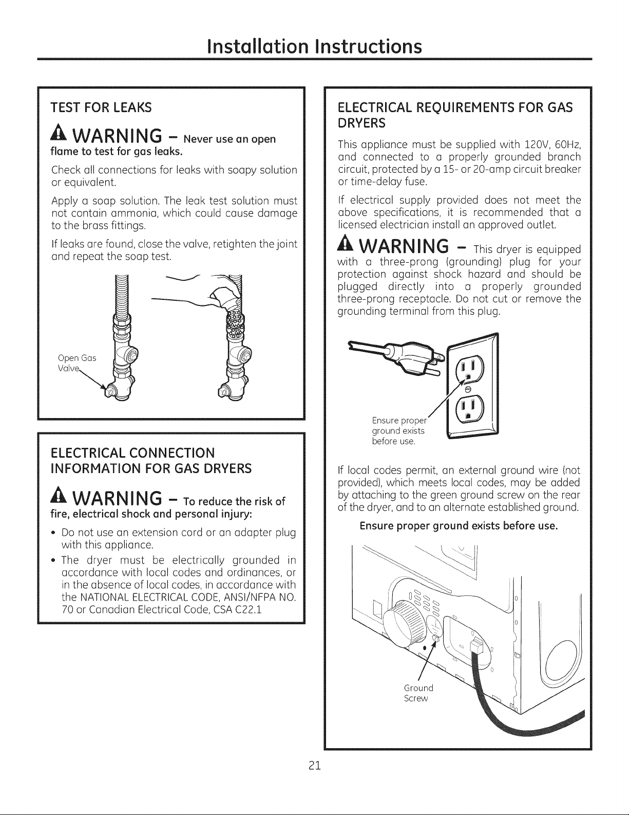
TEST FOR LEAKS
WARNING - Never useanopen
flame to test for gas leaks.
Check all connections for leaks with soapy solution
or equivalent.
Apply a soap solution. The leak test solution must
not contain ammonia, which could cause damage
to the brass fittings.
If leaks are found, close the valve, retighten the joint
and repeat the soap test.
Open Gas
ELECTRICAL CONNECTION
INFORMATION FOR GAS DRYERS
A WARNING - Toreducetheriskof
fire, electrical shock and personal injury:
. Do not use an extension cord or an adapter plug
with this appliance.
. The dryer must be electrically grounded in
accordance with local codes and ordinances, or
in the absence of local codes, in accordance with
the NATIONAL ELECTRICAL CODE, ANSI/NFPA NO.
70 or Canadian Electrical Code, CSA C22.1
ELECTRICAL REQUIREMENTS FOR GAS
DRYERS
This appliance must be supplied with 120V, 60Hz,
and connected to a properly grounded branch
circuit, protected by a 15- or 20-amp circuit breaker
or time-delay fuse.
If electrical supply provided does not meet the
above specifications, it is recommended that a
licensed electrician install an approved outlet.
A WARNING - Thisdryerisequipped
with a three-prong (grounding) plug for your
protectionagainst shock hazard and should be
plugged directly into a properly grounded
three-prongreceptacle.Do not cut or remove the
groundingterminalfrom thisplug.
/II IIII
Ensure proper
ground exists
before use.
If local codes permit, an external ground wire (not
provided), which meets local codes, may be added
by attaching to the green ground screw on the rear
of the dryer, and to an alternate established ground.
Ensure proper ground exists before use.
21
Ground
Screw
InstallationInstructions
CONNECTING AN ELECTRIC DRYER {skipfor gas dryers)
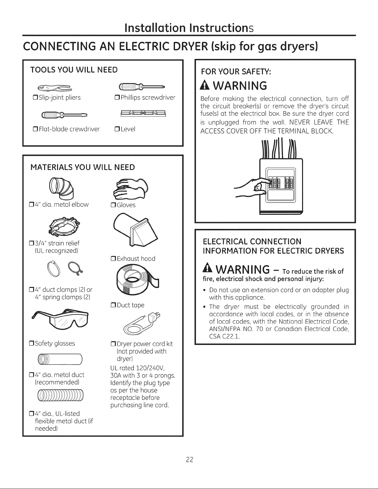
TOOLS YOU WILL NEED
OSlip-joint pliers
O Phillips screwdriver
__,====_
O Flat-blade crewdriver
MATERIALS YOU WILL NEED
O4" dia. metal elbow
O Level
OGIoves
%
O3/4" strain relief
(UL recognized)
0 Exhaust hood
FOR YOUR SAFETY:
A WARNING
Before making the electrical connection, turn off
the circuit breaker(s) or remove the dryer's circuit
fuse(s) at the electrical box. Be sure the dryer cord
is unplugged from the wall. NEVER LEAVE THE
ACCESS COVER OFF THE TERMINAL BLOCK.
ELECTRICAL CONNECTION
INFORMATION FOR ELECTRIC DRYERS
%
04" duct clamps (2)or
4" spring clamps (2)
0 Safety glasses
04" dia. metal duct
(recommended)
04" dia., UL-listed
flexible metal duct (if
needed)
O Duct tape
0 Dryer power cord kit
(not provided with
dryer)
UL rated 120/240V,
30A with 3 or 4 prongs.
Identify the plug type
as per the house
receptacle before
purchasing line cord.
A WARNING - Toreducetheriskof
fire, electrical shock and personal injury:
. Do not use an extension cord or an adapter plug
with this appliance.
. The dryer must be electrically grounded in
accordance with local codes, or in the absence
of local codes, with the National Electrical Code,
ANSI/NFPA NO. 70 or Canadian Electrical Code,
CSA C22.1.
22
Installation Instructions
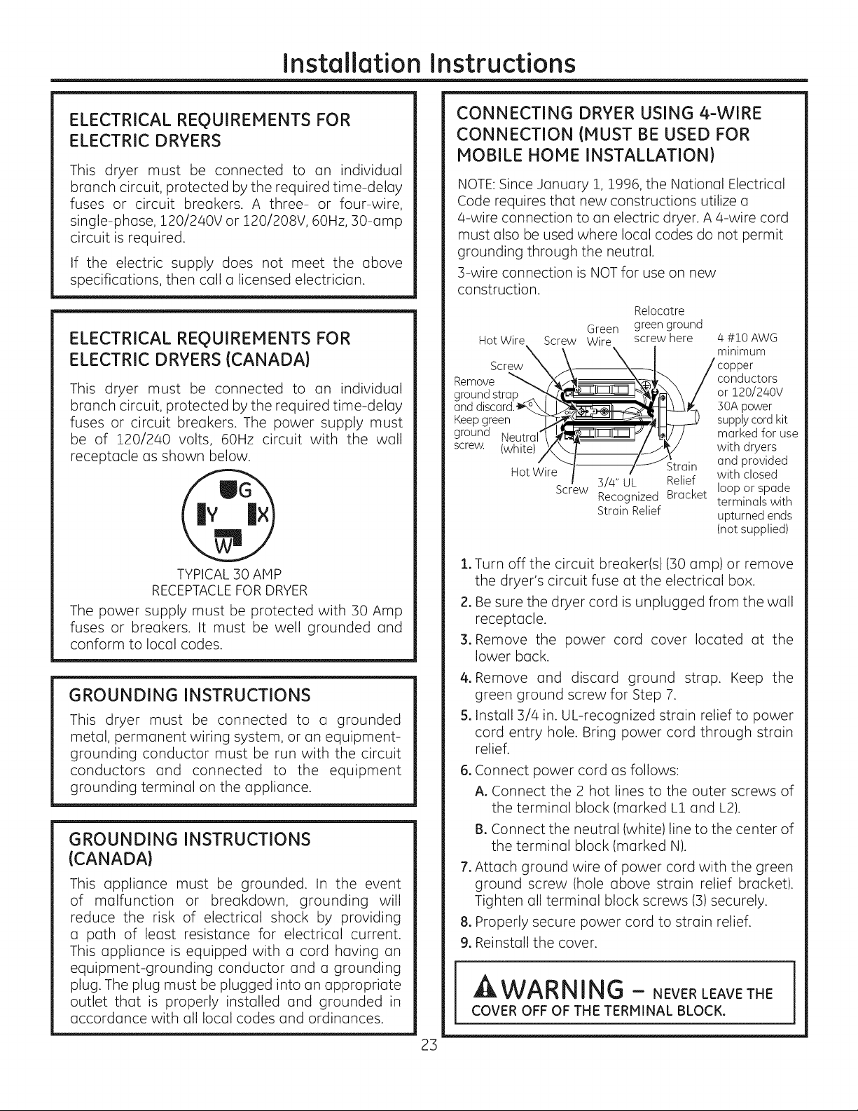
ELECTRICAL REOUIREMENTS FOR
ELECTRIC DRYERS
This dryer must be connected to an individual
branch circuit, protected by the required time-delay
fuses or circuit breakers. A three- or four-wire,
single-phase, 120/240V or 120/208V, 60Hz, 30-amp
circuit is required.
If the electric supply does not meet the above
specifications, then call a licensed electrician.
ELECTRICAL REQUIREMENTS FOR
ELECTRIC DRYERS (CANADA)
This dryer must be connected to an individual
branch circuit, protected by the required time-delay
fuses or circuit breakers. The power supply must
be of 120/240 volts, 60Hz circuit with the wall
receptacle as shown below.
CONNECTING DRYER USING 4-WIRE
CONNECTION (MUST BE USED FOR
MOBILE HOME INSTALLATION)
NOTE:Since January 1, 1996, the National Electrical
Code requires that new constructions utilize a
4-wire connection to an electric dryer. A 4-wire cord
must also be used where local codes do not permit
grounding through the neutral.
3-wire connection is NOT for use on new
construction.
Relocatre
Green green ground
Hot Wire Screw Wire screw here /4#10 AWG
Screw I minimum
Remove
ground strap
and
Keepgreen
ground Neutral
screw. (white)
Hot Wire Strain
Screw 3//4" UL Relief
Recognized Bracket
Strain Relief
conductors
or 120/2/40V
30A power
supply cord kit
marked for use
with dryers
and provided
with closed
loop or spade
terminals with
upturned ends
(not supplied)
TYPICAL 30 AMP
RECEPTACLEFOR DRYER
The power supply must be protected with 30 Amp
fuses or breakers. It must be well grounded and
conform to local codes.
GROUNDING INSTRUCTIONS
This dryer must be connected to a grounded
metal, permanent wiring system, or an equipment-
grounding conductor must be run with the circuit
conductors and connected to the equipment
grounding terminal on the appliance.
GROUNDING INSTRUCTIONS
(CANADA)
This appliance must be grounded. In the event
of malfunction or breakdown, grounding will
reduce the risk of electrical shock by providing
a path of least resistance for electrical current.
This appliance is equipped with a cord having an
equipment-grounding conductor and a grounding
plug. The plug must be plugged into an appropriate
outlet that is properly installed and grounded in
accordance with all local codes and ordinances.
.
Turn off the circuit breaker(s) (30 amp) or remove
the dryer's circuit fuse at the electrical box.
2.
Be sure the dryer cord is unplugged from the wall
receptacle.
3.
Remove the power cord cover located at the
lower back.
4.
Remove and discard ground strap. Keep the
green ground screw for Step 7.
5.
Install 3/4 in. UL-recognized strain relief to power
cord entry hole. Bring power cord through strain
relief.
.
Connect power cord as follows:
A. Connect the 2 hot lines to the outer screws of
the terminal block (marked L1 and L2).
B. Connect the neutral (white) line to the center of
the terminal block (marked N).
.
Attach ground wire of power cord with the green
ground screw (hole above strain relief bracket).
Tighten all terminal block screws (3) securely.
.
Properly secure power cord to strain relief.
9.
Reinstall the cover.
A,WARNING - NEVERLEAVETHE
COVER OFF OF THE TERMINAL BLOCK.
23
Installation Instructions
CONNECTING AN ELECTRIC DRYER (cont.)
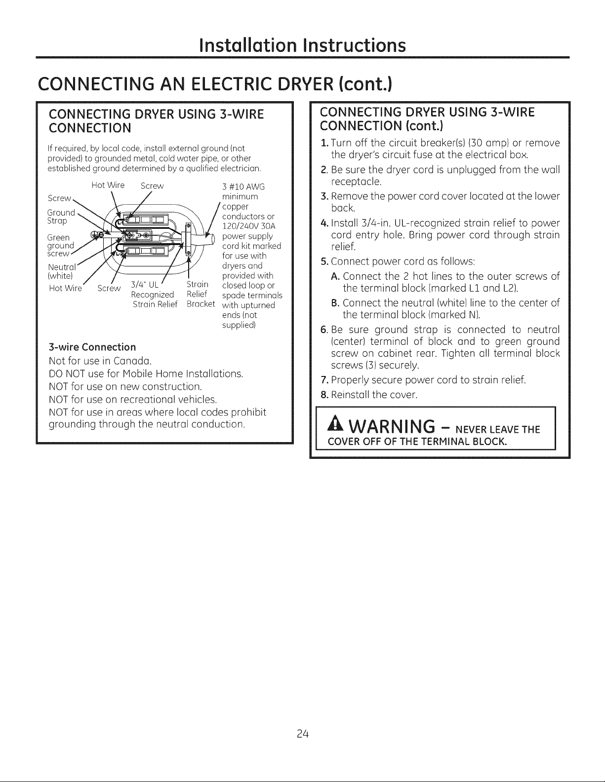
CONNECTING DRYER USING 3-WIRE
CONNECTION
If required, by local code, install external ground (not
provided) to grounded metal, cold water pipe, or other
established ground determined by a qualified electrician.
Hot Wire Screw 3 #10 AWG
minimum
Ground,
Strap
Green
(white)
Hot Screw
3-wire Connection
Not for use in Canada.
DO NOT use for Mobile Home Installations.
NOT for use on new construction.
NOT for use on recreational vehicles.
NOT for use in areas where local codes prohibit
grounding through the neutral conduction.
3/4" UL Strain
Recognized Relief
Strain Relief Bracket
conductors or
120/240V 50A
power supply
cord kit marked
for use with
dryers and
provided with
closed loop or
spade terminals
with upturned
ends (not
supplied)
CONNECTING DRYER USING 3-WIRE
CONNECTION (cont.)
1oTurn off the circuit breaker(s) (30 amp) or remove
the dryer's circuit fuse at the electrical box.
2. Be sure the dryer cord is unplugged from the wall
receptacle.
3, Remove the power cord cover located at the lower
back.
4, Install 3/4-in. UL-recognized strain relief to power
cord entry hole. Bring power cord through strain
relief.
5oConnect power cord as follows:
A. Connect the 2 hot lines to the outer screws of
the terminal block (marked L1 and L2).
BoConnect the neutral (white) line to the center of
the terminal block (marked N).
6. Be sure ground strap is connected to neutral
(center) terminal of block and to green ground
screw on cabinet rear. Tighten all terminal block
screws (3) securely.
7, Properly secure power cord to strain relief.
8, Reinstall the cover.
WARNING - NEVERLEAVETHE
COVER OFF OF THE TERMINAL BLOCK.
24
Installation Instructions
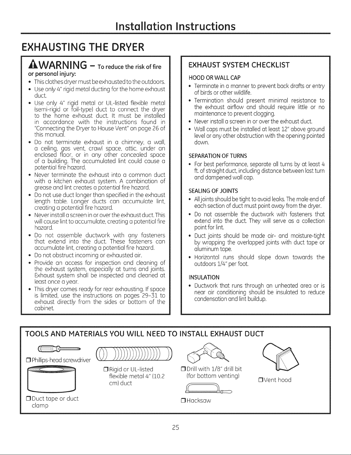
EXHAUSTING THE DRYER
WARNING - To reduce the risk of fire
or personal injury:
, This clothes dryer must be exhausted to the outdoors.
, Use only 4" rigid metal ducting for the home exhaust
duct.
, Use only 4" rigid metal or UL-listed flexible metal
(semi-rigid or foil-type) duct to connect the dryer
to the home exhaust duct. It must be installed
in accordance with the instructions found in
"Connecting the Dryer to House Vent" on page 26 of
this manual.
, Do not terminate exhaust in a chimney, a wall,
a ceiling, gas vent, crawl space, attic, under an
enclosed floor, or in any other concealed space
of a building. The accumulated lint could cause a
potential fire hazard.
, Never terminate the exhaust into a common duct
with a kitchen exhaust system. A combination of
grease and lint creates a potential fire hazard.
, Do not use duct longer than specified in the exhaust
length table. Longer ducts can accumulate lint,
creating a potential fire hazard.
, Never install a screen in or over the exhaust duct. This
will cause lint to accumulate, creating a potential fire
hazard.
, Do not assemble ductwork with any fasteners
that extend into the duct. These fasteners can
accumulate lint, creating a potential fire hazard.
, Do not obstruct incoming or exhausted air.
, Provide an access for inspection and cleaning of
the exhaust system, especially at turns and joints.
Exhaust system shall be inspected and cleaned at
least once a year.
, This dryer comes ready for rear exhausting. If space
is limited, use the instructions on pages 29-31 to
exhaust directly from the sides or bottom of the
cabinet.
EXHAUST SYSTEM CHECKLIST
HOOD OR WALL CAP
• Terminate in a manner to prevent back drafts or entry
of birds or other wildlife.
• Termination should present minimal resistance to
the exhaust airflow and should require little or no
maintenance to prevent clogging.
• Never install a screen in or over the exhaust duct.
• Wall caps must be installed at least 12" above ground
level or any other obstruction with the opening pointed
down.
SEPARATIONOF TURNS
Forbest performance,separateallturns by at least/4
ft.of straightduct,includingdistancebetweenlastturn
anddampenedwall cap.
SEALINGOFJOINTS
• Alljoints should be tight to avoid leaks. The male end of
each section of duct must point away from the dryer.
• Do not assemble the ductwork with fasteners that
extend into the duct. They will serve as a collection
point for lint.
• Duct joints should be made air- and moisture-tight
by wrapping the overlapped joints with duct tape or
aluminum tape.
• Horizontal runs should slope down towards the
outdoors 1/4" per foot.
INSULATION
Ductwork that runs through an unheated area or is
near air conditioning should be insulated to reduce
condensation and lint buildup.
TOOLS AND MATERIALS YOU WILL NEED TO INSTALL EXHAUST DUCT
17Phillips-head screwdriver
17Rigid or UL-listed
flexible metal 4" (10.2
cm) duct
C1Duct tape or duct
clamp
17Drill with 1/8" drill bit
(for bottom venting)
17Hacksaw
25
C1Vent hood
Installation Instructions
EXHAUSTING THE DRYERIcont.)
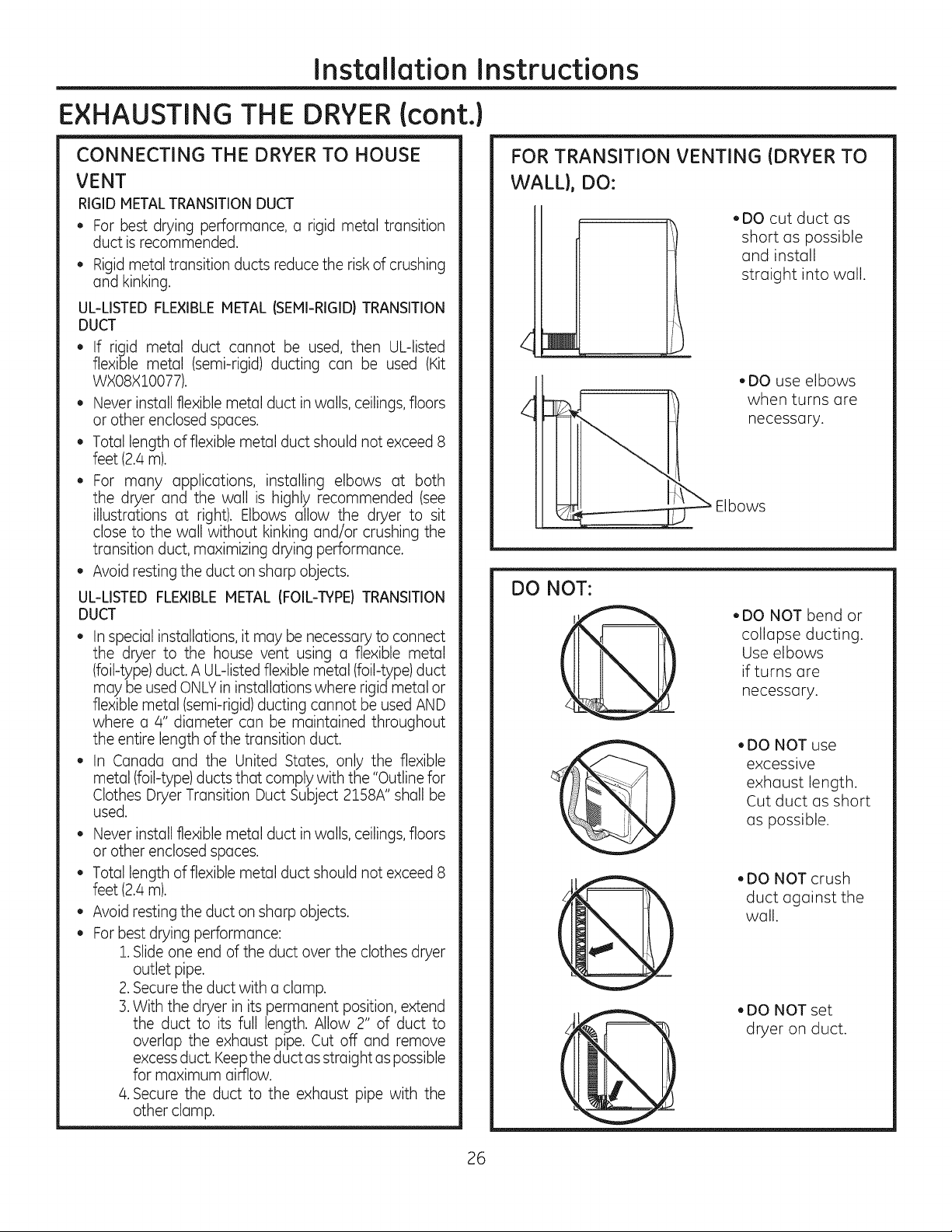
CONNECTING THE DRYER TO HOUSE
VENT
RIGID METALTRANSITIONDUCT
• For best drying performance, a rigid metal transition
duct is recommended.
• Rigid metal transition ducts reduce the risk of crushing
and kinking.
UL-LISTED FLEXIBLEMETAL ISEMI-RIGID) TRANSITION
DUCT
• If rigid metal duct cannot be used, then UL-listed
flexible metal (semi-rigid)ducting can be used (Kit
WXO8XlO077).
• Never install flexible metal duct in walls, ceilings, floors
or other enclosed spaces.
• Total length of flexible metal duct should not exceed 8
feet (2./4m).
• For many applications, installing elbows at both
the dryer and the wall is highly recommended (see
illustrations at right). Elbows allow the dryer to sit
close to the wall without kinking and/or crushing the
transition duct, maximizing drying performance.
• Avoid resting the duct on sharp objects.
UL-LISTED FLEXIBLE METAL IFOIL-TYPE) TRANSITION
DUCT
• In special installations, it may be necessary to connect
the dryer to the house vent using a flexible metal
(foil-type) duct. A UL-listed flexible metal (foil-type)duct
may be used ONLYin installations where rigid metal or
flexible metal (semi-rigid) ducting cannot be used AND
where a 4" diameter can be maintained throughout
the entire length of the transition duct.
• In Canada and the United States, only the flexible
metal (foil-type) ducts that comply with the "Outline for
Clothes Dryer Transition Duct Subject 2158A" shall be
used.
Never install flexible metal duct in walls, ceilings, floors
or other enclosed spaces.
Total length of flexible metal duct should not exceed 8
feet (2./4m).
Avoid resting the duct on sharp objects.
For best drying performance:
1.Slide one end of the duct over the clothes dryer
outlet pipe.
2.Secure the duct with a clamp.
3.With the dryer in its permanent position, extend
the duct to its full length. Allow 2" of duct to
overlap the exhaust pipe. Cut off and remove
excess duct. Keepthe duct asstraight aspossible
for maximum aidlow.
/4.Secure the duct to the exhaust pipe with the
other clamp.
FOR TRANSITION VENTING (DRYER TO
WALL), DO:
,DO cut duct as
short as possible
and install
straight into wall.
,DO use elbows
when turns are
necessary.
bows
DO NOT:
• DO NOT bend or
collapse ducting.
Use elbows
if turns are
'@
necessary.
. DO NOT use
excessive
exhaust length.
Cut duct as short
as possible.
. DO NOT crush
duct against the
wall.
. DO NOT set
dryer on duct.
26
Installation Instructions
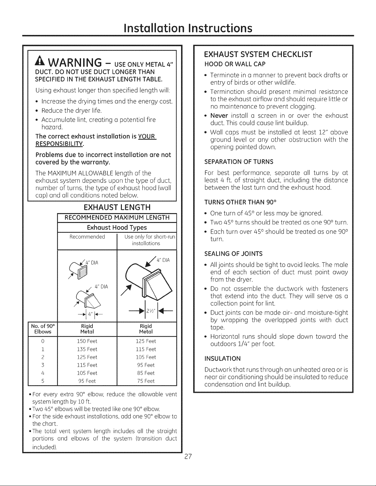
WARNING - USEONLYMETAL4"
DUCT. DO NOT USE DUCT LONGER THAN
SPECIFIED IN THE EXHAUST LENGTH TABLE.
Using exhaust longer than specified length will:
, Increase the drying times and the energy cost.
, Reduce the dryer life.
, Accumulate lint, creating a potential fire
hazard.
The correct exhaust installation is YOUR
RESPONSIBILITY.
Problems due to incorrect installation are not
covered by the warranty.
The MAXIMUM ALLOWABLE length of the
exhaust system depends upon the type of duct,
number of turns, the type of exhaust hood (wall
cap) and all conditions noted below.
EXHAUST LENGTH
RECOMMENDED MAXIMUM LENGTH
Exhaust Hood Types
Recommended Useonly for short-run
4" DIA
4" DIA
No. of 90°
Elbows
0
1
2
3
4
5
Rigid
Metal
150 Feet
155 Feet
125 Feet
115 Feet
105 Feet
95 Feet
. For every extra 90° elbow, reduce the allowable vent
system length by !0 ft.
.Two 45° elbows will betreated like one 90° elbow.
. For the side exhaust installations, add one 90° elbow to
the chart.
.The total vent system length includes all the straight
portions and elbows of the system (transition duct
included).
installations
_,,,'/4" DIA
Rigid
Metal
125 Feet
115 Feet
105 Feet
95 Feet
85 Feet
75 Feet
EXHAUST SYSTEM CHECKLIST
HOOD OR WALL CAP
, Terminate in a manner to prevent back drafts or
entry of birds or other wildlife.
, Termination should present minimal resistance
to the exhaust airflow and should require little or
no maintenance to prevent clogging.
, Never install a screen in or over the exhaust
duct. This could cause lint buildup.
, Wall caps must be installed at least 12" above
ground level or any other obstruction with the
opening pointed down.
SEPARATION OF TURNS
For best performance, separate all turns by at
least 4 ft. of straight duct, including the distance
between the last turn and the exhaust hood.
TURNS OTHER THAN 90°
, One turn of 45 ° or less may be ignored.
, Two 45 ° turns should be treated as one 90° turn.
, Each turn over 45 ° should be treated as one 90°
turn.
SEALING OF JOINTS
, All joints should be tight to avoid leaks. The male
end of each section of duct must point away
from the dryer.
, Do not assemble the ductwork with fasteners
that extend into the duct. They will serve as a
collection point for lint.
, Duct joints can be made air- and moisture-tight
by wrapping the overlapped joints with duct
tape.
, Horizontal runs should slope down toward the
outdoors 1/4" per foot.
INSULATION
Ductwork that runs through an unheated area or is
near air conditioning should be insulated to reduce
condensation and lint buildup.
27
Installation Instructions
EXHAUSTING THE DRYER{cont.)
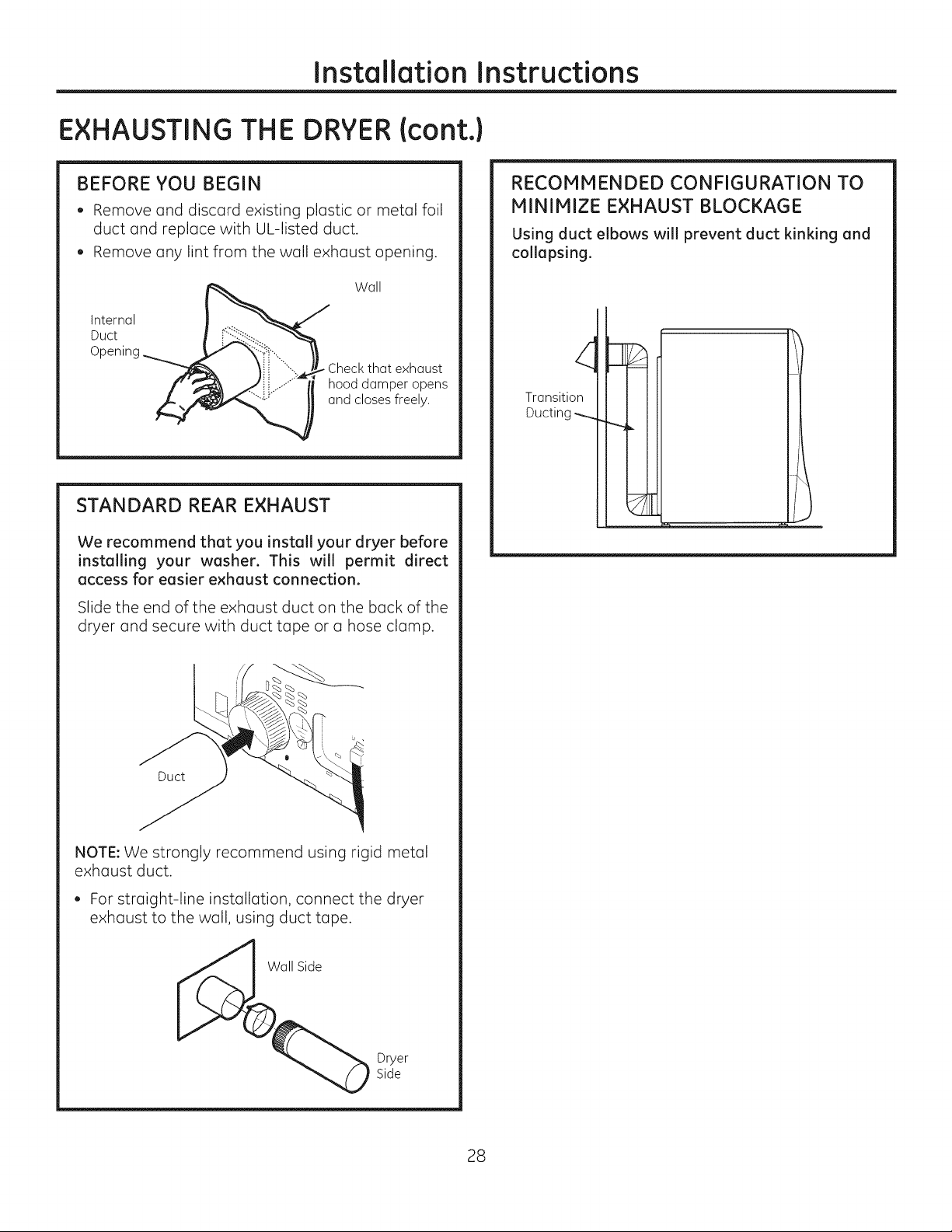
BEFORE YOU BEGIN
, Remove and discard existing plastic or metal foil
duct and replace with UL-listed duct.
, Remove any lint from the wall exhaust opening.
Wall
Internal
Duct
Check that exhaust
hood damper opens
and closes freely.
STANDARD REAR EXHAUST
We recommend that you install your dryer before
installing your washer. This will permit direct
access for easier exhaust connection.
Slide the end of the exhaust duct on the back of the
dryer and secure with duct tape or a hose clamp.
RECOMMENDED CONFIGURATION TO
MINIMIZE EXHAUST BLOCKAGE
Using duct elbows will prevent duct kinking and
collapsing.
Transition
Ducting
Duct
NOTE: We strongly recommend using rigid metal
exhaust duct.
, For straight-line installation, connect the dryer
exhaust to the wall, using duct tape.
all Side
Dryer
Side
28
Installation Instructions
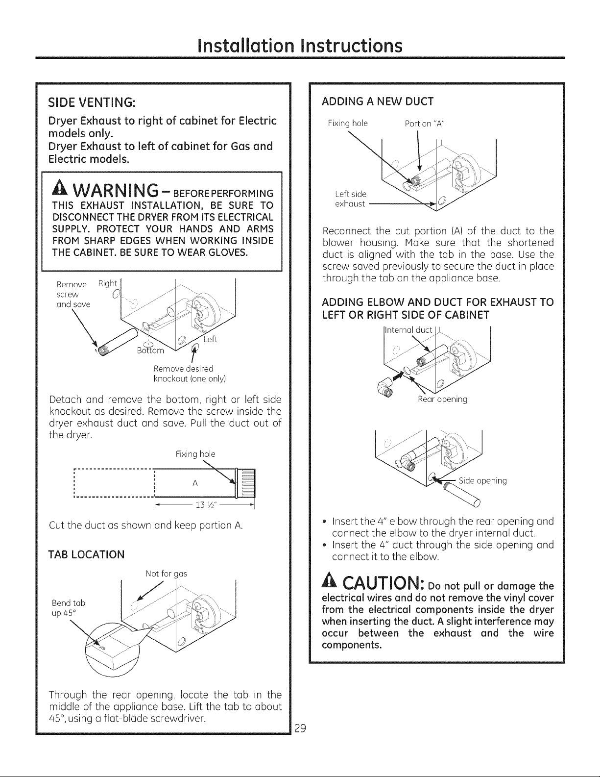
SIDE VENTING:
Dryer Exhaust to right of cabinet for Electric
models only.
Dryer Exhaust to left of cabinet for Gas and
Electric models.
WARNING- BEFOREPERFORMING
THiS EXHAUST INSTALLATION, BE SURE TO
DISCONNECT THE DRYER FROM iTS ELECTRICAL
SUPPLY. PROTECT YOUR HANDS AND ARMS
FROM SHARP EDGES WHEN WORKING INSIDE
THE CABINET. BE SURE TO WEAR GLOVES.
Remove Right
screw
and save
Left
Remove desired
knockout (one only)
ADDING A NEW DUCT
Fixing hole Portion "A"
Lef _..., _"_
exhaust ,..._
Reconnect the cut portion (A) of the duct to the
blower housing. Make sure that the shortened
duct is aligned with the tab in the base. Use the
screw saved previously to secure the duct in place
through the tab on the appliance base.
ADDING ELBOW AND DUCT FOR EXHAUST TO
LEFT OR RIGHT SIDE OF CABINET
nternal duct
Detach and remove the bottom, right or left side
knockout as desired. Remove the screw inside the
dryer exhaust duct and save. Pull the duct out of
the dryer.
Fixing hole
Cut the duct as shown and keep portion A.
TAB LOCATION
Notfor gas
Bend tab
up 45 °
Rear opening
Side opening
, Insert the 4" elbow through the rear opening and
connect the elbow to the dryer internal duct.
, Insert the 4" duct through the side opening and
connect it to the elbow.
A CAUTION: Donotpu,or damage the
electrical wires and do not remove the vinyl cover
from the electrical components inside the dryer
when inserting the duct. A slight interference may
occur between the exhaust and the wire
components.
Through the rear opening, locate the tab in the
middle of the appliance base. Lift the tab to about
45°, using a flat-blade screwdriver.
29
Installation Instructions
EXHAUSTING THE DRYER(cont.)
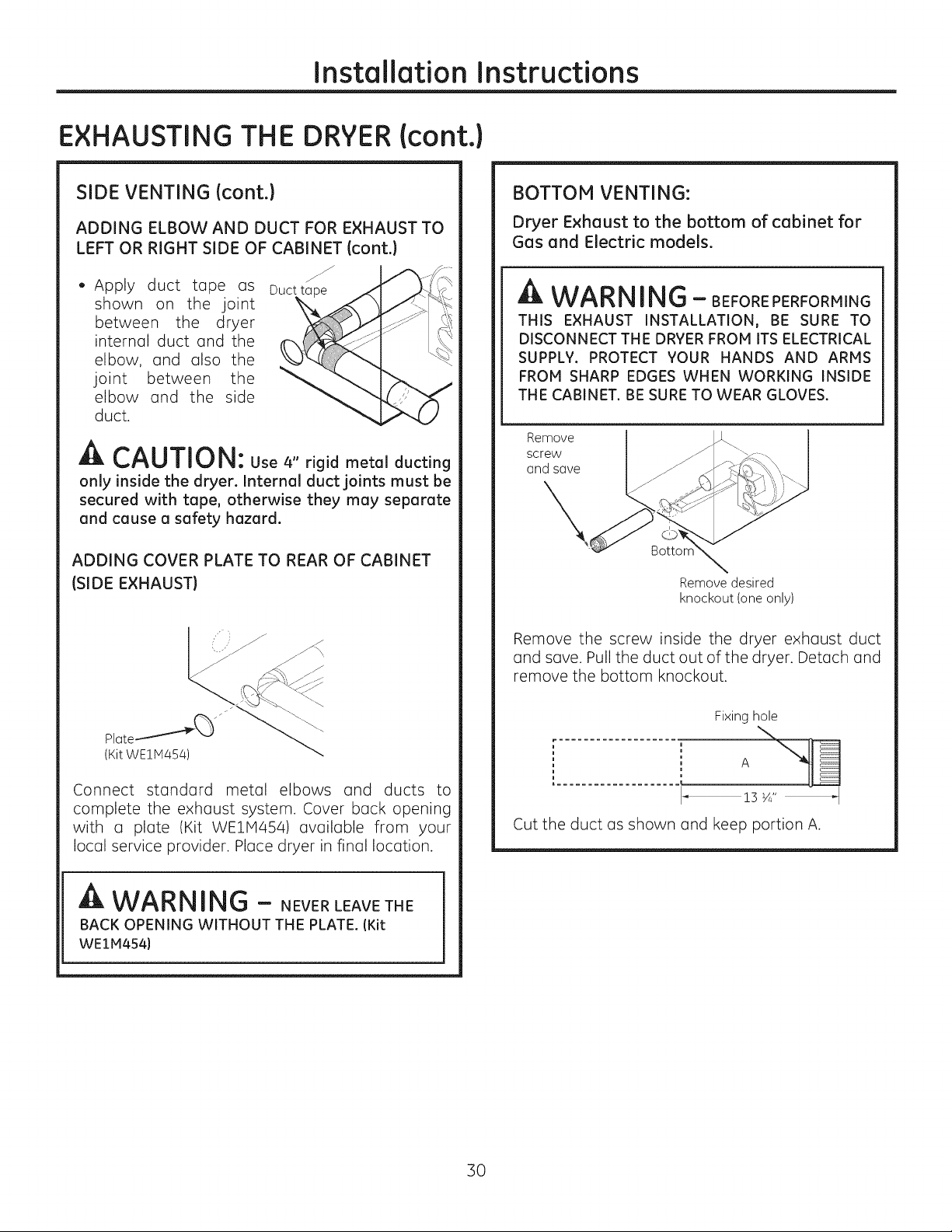
SIDE VENTING (cont.)
ADDING ELBOW AND DUCT FOR EXHAUST TO
LEFT OR RIGHT SIDE OF CABINET (cont.}
, Apply duct tope as
shown on the joint
between the dryer
internal duct and the
elbow, and also the
joint between the
elbow and the side
duct.
jJ
Duct ta
A CAUTION: Use 4" rigid metal ducting
only inside the dryer. Internal duct joints must be
secured with tope, otherwise they may separate
and cause a safety hazard.
ADDING COVER PLATE TO REAR OF CABINET
(SIDE EXHAUST}
j zf
BOTTOH VENTING:
Dryer Exhaust to the bottom of cabinet for
Gas and Electric models.
_k WA RNING- BEFOREPERFORMING
THIS EXHAUST INSTALLATION, BE SURE TO
DISCONNECT THE DRYER FROM ITS ELECTRICAL
SUPPLY. PROTECT YOUR HANDS AND ARMS
FROM SHARP EDGES WHEN WORKING INSIDE
THE CABINET. BE SURE TO WEAR GLOVES.
Remove
screw
and save
Bottor
Remove desired
knockout (one only)
Remove the screw inside the dryer exhaust duct
and save. Pull the duct out of the dryer. Detach and
remove the bottom knockout.
(Kit WE1M454)
Connect standard metal elbows and ducts to
complete the exhaust system. Cover back opening
with u plate (Kit WEIM454) available from your
local service provider. Place dryer in final location.
WARNING - NEVERLEAVETHE
BACK OPENING WITHOUT THE PLATE. (Kit
WE1M454}
Fixing hole
L.................... _
!3 Y4"_1
Cut the duct as shown and keep portion A.
30
 Loading...