

GE PFSS5NJWASS, PFSS5NFWASS, PFSF5NJWAWW, PFSF5NJWACC, PFSF5NFWAWW Owner’s Manual
...
0
r/3
ge.com
Safety Instructions ........... 2, 3
Operating Instru_tions
Additional Features ............. S
Automatic Icemaker ........... 11
Care and Cleaning .......... 12-13
Controls .................... 4-5
Crispers and Pans .............. 9
Freezer ...................... 10
Repl acing the i,igh t Bul bs ....... 14
Shelves and Bins ............. 7, S
_'ater Filter . .................. 6
Installation InsTtructions
Installing the Anti-Tip
Floor Bracket .............. 18-19
Installing the Refrigerator .... 20-24
Installing the _'ater Line ..... 33-35
Preparing to Install
the Refligeratnr ............... 17
Removing and Replacing the
Freezer Drawer . ........... 25, 26
Reversing the Door Swing
(Single Door Refrigerator
Models only) .............. 27-29
Removing and Replacing
the Doors (Double Door
Refrigerator Models only) .... 30-32
Trim Kits and Decorator
Panels .................... 15-16
Models21 and25
Cong_lateur inf&ieur
R frig rateurs
La section fran_aise commencea la page 49
Congelador inferior
Refrigeradores
La seccion en espaOolempiezaen la pagina 93
Troubleshooting Tips ....... 36-40
Normal Operating Sounds ...... 36
Consumer Support
Consumer Support ..... Back Cover
Performance Data Sheet ........ 47
Product Registration
for Canadian Customers ..... 43, 44
Product Registration
fox U.S. Customers ......... 41,42
State of California ¼'ater
Treatment Device Certificate ..... 48
¼'arranty fox" Canadian
Customers ................... 46
V(arranty fox" U.S. Customers ..... 45
Writethe modelandserial
numbershere:
Model #
Serial #
Find these nmnbe_ on a label
on the right side, near the top of
the refrigerator compartment.
200D9366PO01 49-60489 !2-06 dR
IMPORTANTSAFE INFORMATION,
READALLINSTRUCTIONSBEFOREUSING.
WARNING!
Use this appliance only for its intended purpose as described in this Owner's Manual.
SAFETYPRECAUTIONS
When using electrical appliances, basic safety precautions should be followed, including the following:
This reflJgerator must be properl) installed
and located in accordance with the Installation
hlstrucfions before it is used.
Do not allow children to climb, stand or hang
on the shelves in the refl-Jgeratm: They could
damage the refl-Jgerator and seriously iqjm'e
themselves.
Do not touch the cold surfi_ces in the fl'eezer
compartment when hands are damp or wet.
Skin max stick to these extremely cold SUll'ilces.
_ Do not store or use gasoline or other flammable
wq)ors and liquids in the viciniP,' of this or anv
other appliance.
Keep finge_ out of the "pinch point" areas;
clearances between the doors and between
the (loo_s and cabinet are necessarily small.
Be caretul closing doms when children are
in the area.
In refl'Jgeratm_ Mth automatic icemake_,
avoid contact with the moving parts of the
ejector mechanism, or with the heating element
that releases the cubes. Do not place finge_s or
hands on the automatic icemaking mechanism
while the refi-igerator is plugged in.
Unplug the reflJgerator before cleaning and
making repahs.
NOTE: Westronglyrecommendthatany servicingbe
performedby aquafified individual
Setting either or both controls to 0 (off) does
not reil/ove power to the light circuit.
{ Do not reti'eeze frozen toods which have
thawed complemly.
A DANGER!RISKOFCHILDENTRAPMENT
PROPERDISPOSALOFTHEREFRIGERATOR
Refrigerants
of the past. Junked or abandoned refl'igeratots are
Child entrapnlent and suffocation are not problems
still dangerous...exert if they will sit for 'ijust a few
daxs." If _ou are _*etting rid of xom" old refrigeratm;
please follow the instructions below to help prevent
accidents.
Before YouThrewAway YourOldRefrigerator
All refi'igeration products contain refi'igerants,
which under fe(leral law must be removed prior
to product disposal. If you are getting rid of
an old refi'igeration product, check with the
company handling the disposal about what
to do.
or Freezer:
_ke off the dome.
i,eaxe the shelxes in place so that children may
not easil_ climb inside.
USEOFEXTENSIONCORDS
Because of potential safety hazards under certain conditions, we strongly recommend against
the use of an extension cord.
However, if you must use an extension cord, it is absolutelx necessary that it be a Ui,-listed (in the United
States) or a CSA certified (in Canada), B-wire ,gr°unding, t',,l)e appliance extension cord having a gro/mding
2
t)l_e I)lu'"-,and outlet and that the electrical rating of the cord be 15 amperes (minimum) and 120 xolts.
WARNING!
HOWTOCONNECTELECTRICITY
Donot, under anv circumstances, cut or remove the third (ground) prong from the power cord.
For personal safe_ this appliance must be properly grounded.
ge.com
The power cord of this appliance is equipped
with a 3-prong (gromMing) plug which mates
with a standard 3-prong (grounding) wall outlet to
minimize the possibili_, of electric shock hazard
fi'om this appliance.
Have the wall outlet and circuit checked by a
qualNed electridan to make sure the outlet is
properly gromMed.
Where a standard 2-prong wall outlet is
encountered, it is your pex_onal responsibili_' and
obligation to have it replaced with a propedy
grounded 3-prong wall outlet.
The refl_igerator should always be plugged into its
own individual electrical outlet which has a voltage
rating that matches the rating plate.
This provides the best perlommnce and also
I)rexents oxerloading, house wiring circuits which
could cause a fire hazard from oxerheated wires.
Never unplug yore" refrigerator by pulling on the
power cord. Mways grip plug firefly and pull
straight out ti'oln the outlet.
Repair or replace immediately all power cords that
have become fl'ayed or otherwise damaged. Do not
use a cord that shows cracks or abrasion damage
along its length or at either end.
\4]_en moving the refl_igerator away fl'om the
wall, be carefld not to roll over or damage the
power cord.
READANDFOLLOWTHISSAFETYINFORMATIONCAREFULLY.
SAVETHESEINSTRUCTIONS
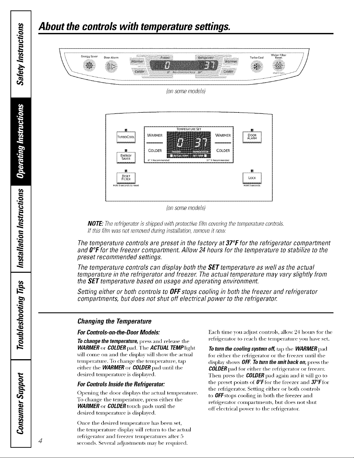
Aboutthe controlswith temperaturesettings.
(onsomemodels)
TEMPERATURE SET
[] []
HOM 3 seconds to reset Ho_d 3 seconds
[]
(onsomemodels)
NOTE: Therefrigeratoris shippedwith protective film coveringthe temperaturecontrols.
If this film was not removedduringinstallation,removeit now
Thetemperature controls are preset in the factory at 37°F for the refrigerator compartment
and O°Ffor the freezer compartment. Allow 24hours for the temperature to stabilize to the
preset recommended settings.
Thetemperature controls can display both the SET temperature as well as the actual
temperature in the refrigerator and freezer. The actual temperature may vary slightly from
the SETtemperature based on usage and operating environment.
Setting either or both controls to OFFstops cooling in both the freezer and refrigerator
compartments, but does not shut off electrical power to the refrigerator.
Changingthe Temperature
For Controls-on-the-DoorModels:
To change the temperature, press and release the
WARMER or COLDER pad. The ACTUAL TEMPlight
will come on and the display will show the actual
temperatm'e. To change the temperatm'e, tap
either the WARMER or COLDER pad tmtil the
desired temperature is displayed.
For ControlsInside the Refrigerator:
Opening the door displa):s the actual temperatm'e.
To change the temperatm'e, press either the
WARMER or COLDER touch pads tmtil the
desired temperature is displayed.
Once the desired temperature has been set,
the temperatm'e display will retm'n to the actual
4
reflJgerator and freezer temperatures atter B
seconds. Several ac!jusunents inav be required.
Each dine )ou a(!iust controls, allow 24 horns tot the
refrigerator to reach the temperatm'e you haxe set.
To turn the cooling system off, trip the WARMER pad
for either the refl_igerator or the fl'eezer tmtil the
display shows OFF.Toturn the unitbackon, press the
COLDER pad fl)r either the refl_igerator or fl'eeze_;
Then press the COLDER pad again and it will go to
the preset points of O°Ffi)r the fl'eezer and 37°Ffi)r
the refiigerato_: Setting either or both controls
to OFFstops cooling in both the fl'eezer and
refi_igerator compartments, but does not shut
off electrical power to the refi_igeratm:
About TurboCooEM(on some models) ge.oom
How it Works
How to Use
Press TurboCool,Tile refrigerator
temperatm'e display will show k c.
_dter rurboCoolis complete, tile
reflJgerator compartment will return
to the original setting.
NOTES:Tile refrigerator temperature
cannot be changed dining
TurboCooL
Tile fl'eezer temperature is not
affected during TurboCooL
_]/en opening tile refrigerator
door (lining YurboCool,tile liras
will continue to rim if they have
cycled on.
)i IIIIi
(onsomemodels)
(onsomemodels)
TurboCoolrapidly cools the refl_igerator
c()ml)artn/ent in order to more quickl)
cool fi)o(ls, Use TurboCoolwhexl adding a
large amount ofibod to tile refiJgerator
comi)artnmnt, putting away fi)ods after they
have been sitting out at room temperature
or when putting away wam_ leftovers. It can
also be used if the reti_igerator has been
without power for an extended period.
Once acfi\:_ted, the compressor will turn on
immediately and tile Imps will cycle on and
off at high speed as needed fi)r eight hom_.
Tile compressor will continue to mn tmfil
tile refl_igerator compartment cools m
approximately 34°F (l °C), then it will cycle
on and off to maintain this setting. _Mter 8
hom_, or if TurboCoolis pressed again, tile
refl_igerator compartment will return to
the original setting.
Door Narm
(onsomemodels)
(onsomemodels)
(onsomemodels)
About Door Alarm (onsomemodels)
Tile door alam_ will so/rod if any
door is open fi)r more than 2 minutes.
Tile beeping stops when you close
tile door,
About Energy Saver (onsomemodels)
This product is equil)ped with an Energy/
Saver teatm'e. Tile refl_igerator is shil)ped
with tile Energ)' Saver teatm'e enabled.
Over time, moisture can fi)m_ on tile fl'ont
surli_ce of the refl_igerator cabinet and
cause rust. If moisture does appear on tile
fl'ont surfi_ce of tile reflJgerator cabinet,
tm'n off tile Energy Saver teatm'e by
pressing and releasing tile ENERGY SAVER
pad on tile control panel.
(onsomemodels)
Aboutthe water filter.(onsomemode/s)
Water Filter Cartridge
The _ater 5]ter cartridge is located h_ the
back Iq>per right cornier of the re{_'i_emtor
CO1)) [)_tl't_)) e m)t.
Filter Bypass Plug
_i_ mmt me the {i]ter b>_/ass piing whe_/ a
rep]acen/ent tilter cartridge Js _mt available.
Tile Jcemaker _rH]] _Ot operate witho_t tile
When to Replace the Filter
There ]s a replacement h_dicator
light i6r the _<_ter filter cartridge ol_ the
temperatm'e display. This light _rH]] t[_'_)
o[_mge to teII yol_ that yol_ m)eed to replace
the tilter soon. The tilter cartridge shol_]d
be replaced _dlen tile repIacemem/t
h/dicator light rams red or if the flo_
/
of water to the dispem/ser or icemaker
decreases.
Replaoeme#tFilters:
Toorderadditio#al filter cartridges
#1theUnited States,visite#r We#site,
go,corn,or call GEParts a_dAccessories,
_R62_,2002.
Fiher Model (;S\_ F
Customers i_/(_mada sho_dd col/suh
the ; e]]ow [ /ages for the _/earest Mabe
Service (_el/teg
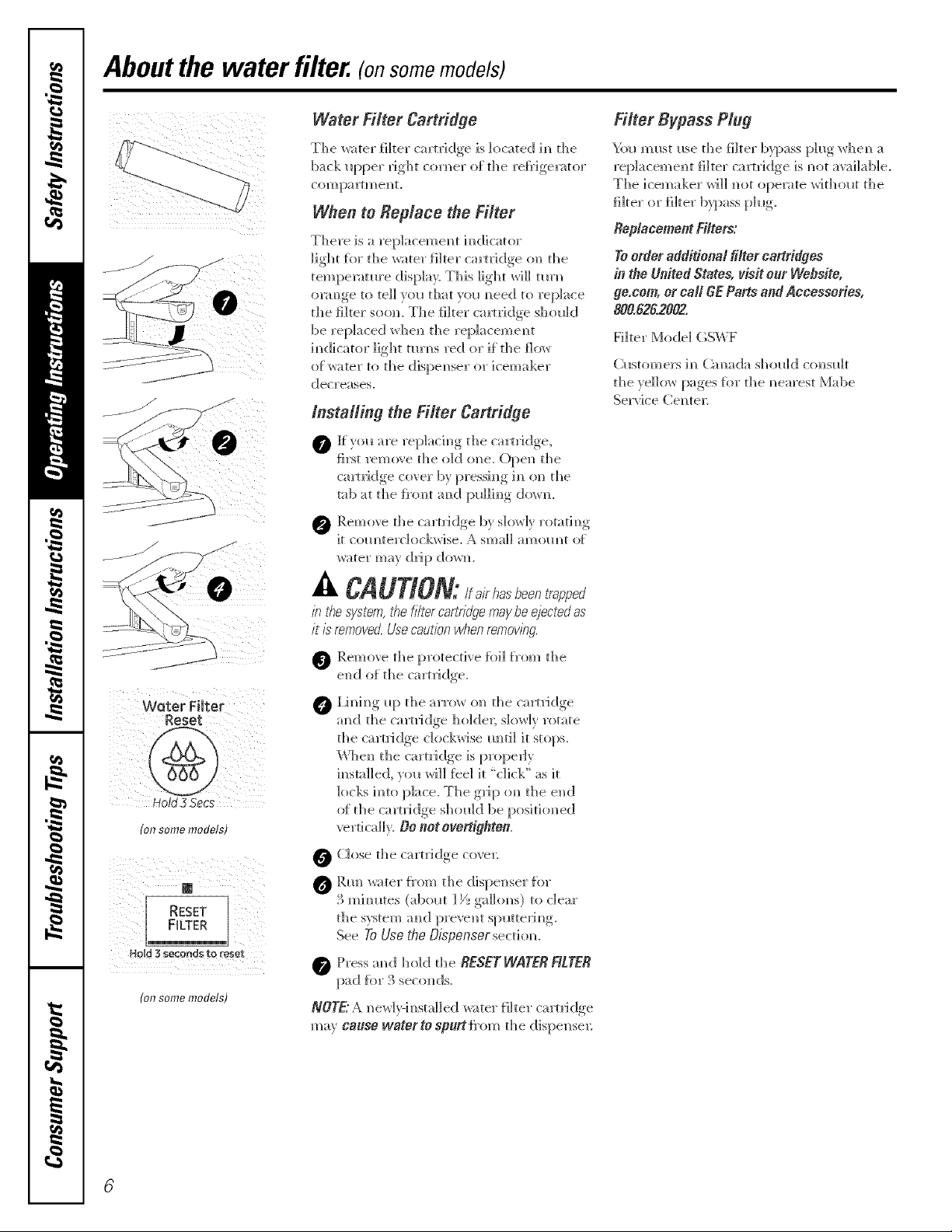
Installing the Filter Cartridge
IJtTOll are repIachlg tile cartridge,
first remole the old oN/e. ()pe_/ the
camidge cover by pressh/g ill on the
tab at tile Jh'om aN/d I:mIIim/g (l_;;;'_/.
0 Remm'e the cartridge b; S]t)_r]_ rotating
it com/terch_ckwise. _ sinai] amolmt of
_ater may drip (]o_rl_.
o ' *
Water Filter
Reset
Hold 3 5ecs
(o/7somemodels)
RESET
FILTER
(onsome models)
CAUTION:lf a/rhasbeen trapped
b the system, the f//tercartr/@e maybe ejectedas
it is removed. Use caution when removing
O Remo'¢e the protective fbi] from the
end _f" the ca rtIi dge.
@ I,h/h/g Iq:/ tile arro_ o_/ tile cartridge
am/(]! tile cartlJdge holder; S]()W1V rotate
tile cartlJdge CIOCktNiSe Ilmltil it stops.
\Vhel/ the camidge is prope@
h/stalled, you wi]] feel it "click" as it
locks h/to piece. The grip <m the el/(]
o_ th e ca rtri dge sh <ml d be posi ti oil ed
verticaIh. DO not ogertigflten.
O Close the cartridge coven
O Rm/_<tter f}'om the dispenser fin"
3 mJmltes (abollt ] _/__ga]hms) to dear
the s}stem and preve_lt slmtterim/g.
See ToUsetheDispensersecdom
0 Press mid hohJ tile RESETWATERFILTER
pad _br 3 seco_/ds.
NOTE"A _/ew] v-i_/sta]] ed _r;_tel" fi] ter ca rtlJ dge
may cause waterto sp_rt fmm the dispel/sex:
Abouttheshelvesandbins. gecem
Not all features are on all models.
Rearranging the Shelves
Shel',es in the refrigerator ('On_l)artn_ent are a(!iustable.
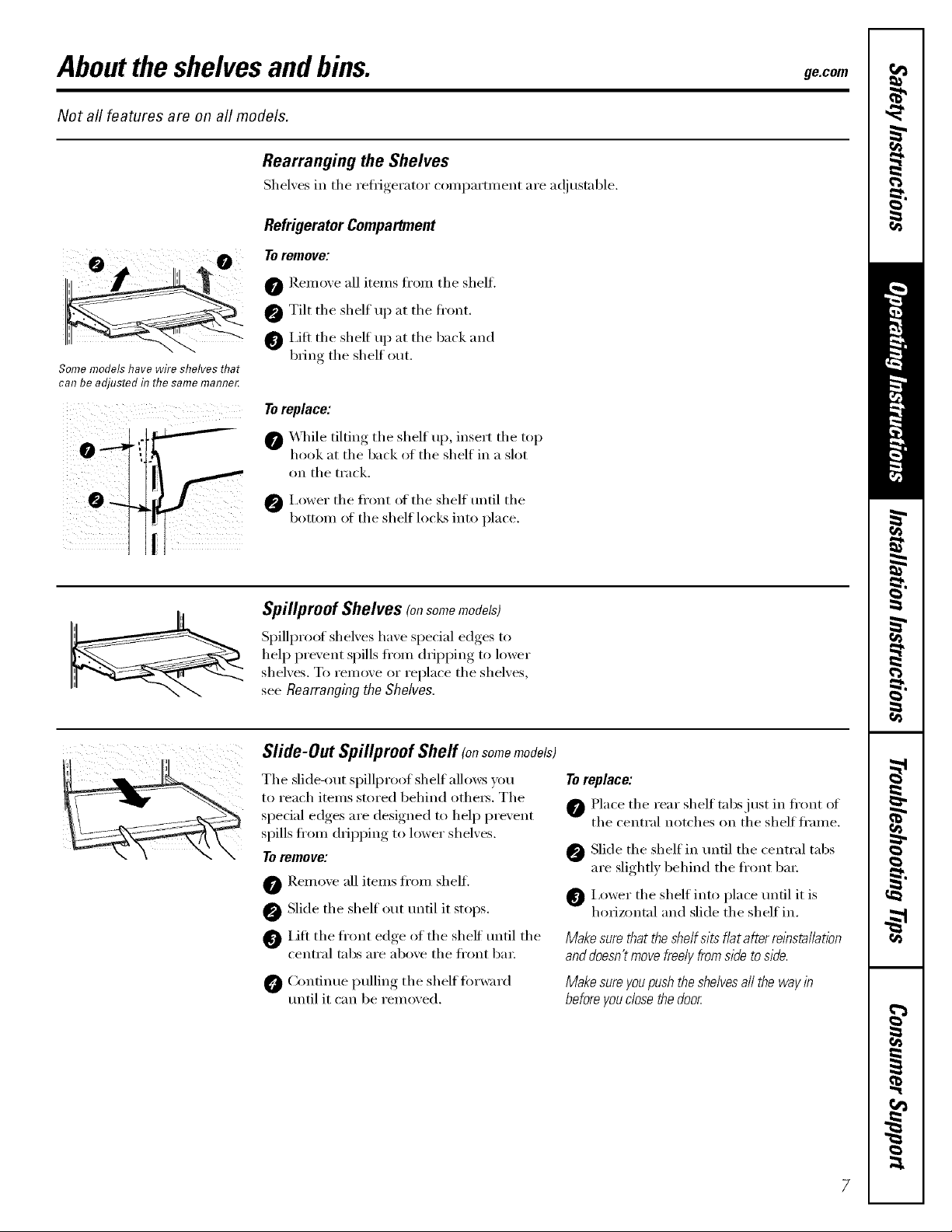
Refrigerator Compartment
To remove:
0 ]_emoxe all items fl'om the shelf.
0 Tilt the shelf up at the fl'ont.
0 I,ifl the shelf u I) at the back and
Some models have wire shelves that
can be adjusted in the same mamTer.
b_l"ng the shelf out.
To replace:
0 _,_q_ile tilting the shelf up, insert the top
hook at the back of the shelf in a slot
on the track.
0 I,ower the fl'ont of the shelf tmtil the
bottom of the shelf locks into place.
Spillproof Shelves (onsomemodels)
Spillproof shelves have special edges to
help prevent spills fl'om dripping to lower
shelves. To ren/ove or replace the shelves,
see Rearranging the Shelves,
Slide-Out Spillproof Sheff (onsomemodels)
The slide-out spillproo/shelf allo_:_ you
to reach items stored behind othe_. The
special edges are designed to help prevent
spills fl'om dripping to lower shelves.
Toremove:
0 Remove all items fl'om shelfi
0 Slide the shelf ()tit until it stops.
0 lift the fl'ont edge of the shelf tmtil the
central tabs are above the fl'ont bin:
0 Continue pulling the shelf torward
tmtil it can be removed.
Toreplace:
0 Place the rear shell tabs just in fl'ont of
the central notches on the shelf fl'ame.
Slide the shelf in tmtil the central tabs
are slightly behind the ti'ont bin:
0 i,ower the shelf into place tmfil it is
horizontal and slide the shelf in.
Make sure that the shelf sits flat after reinstallation
anddoesn't movefreely fromside to side.
Make sure youpushthe shelvesaft the way in
beforeyou dose the door
7
Abouttheshelvesandbins.
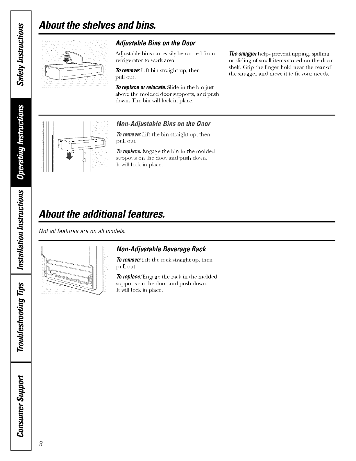
Adjustable Bins on the Door
Ac!iustnble bins can easily be carried fl'on]
I'etiJgeI'_l[oI" 1o wot'k _lI'e_l,
To remove: I,ifi bin straight ui), then
pull out.
To replace orrelocate:Slide in the bin just
above the molded door supports, and push
down, The bin will lock in place,
Non-Adjustable Bins on the Boor
TOremove: 1,1[[ the bim_ st]_ight Iq:>, the]_
pldl <>l_t,
To replace:Em_gage th e bi m_im_th e m(4 ded
sLq:>ports (m the door m_d [:msh (]()_r_.
Jtwill lock im_place.
Abouttheadditionalfeatures.
The snuggerhelps prevent tipping, spilling
or slkling of small items stored on the door
shelf, (h_iI) the finger hold near the rear of
the snugger and move it to fit your needs.
Not all features are on all models.
Non-Adjustable Beverage Rack
To remove: iJfl the rack straight up, then
i)ull out.
To replace:Engage the rack in the molded
supports on the door and push down.
It will lock in place.
8
Aboutthe crispersandpans. gecom
Not all features are on all models.
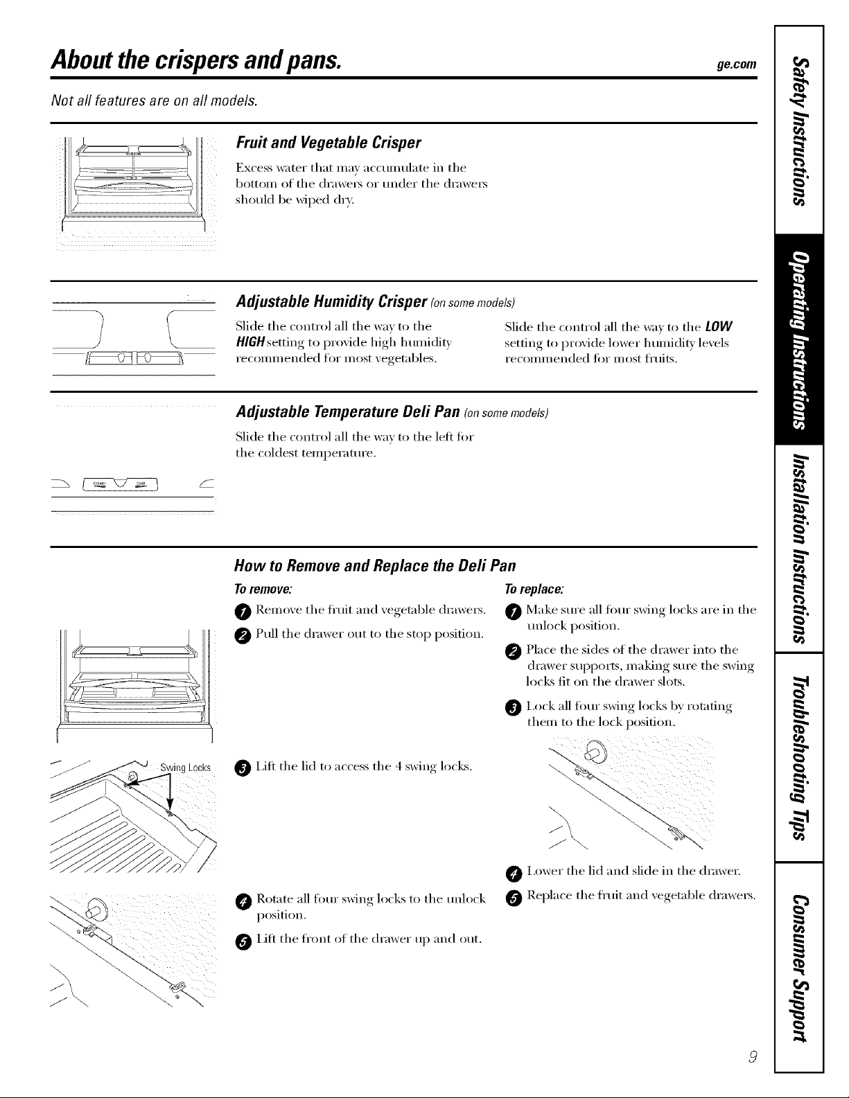
Fruit and Vegetable Crisper
Excess water that ma_ acctmmlate in the
bottom of the (h'awe_ or under the (h'awe_
should be wiped (lr_:
Adjustable Humidity Crisper (onsomemodels)
Slide the control all the way to the Slide the control all the wa_ to the LOW
HlGHsetting to proxide high humidit_ ,setfim*_to proxide lower humidly' lexels
recommended fin" most x egetables, recomm ended fin" most fl'uits.
Adjustable Temperature Deft Pan (onsomemodels)
Slide the control all the way to the left fin,
the coldest temperatm'e.
Rg LOCKS
How to Remove and Replace the Deft Pan
Toremove:
O Remoxe the ti'uit and xegetable (h'awe_.
@Pull the drawer out to the stop position.
I,ifl the lid to access the 4 swing locks.
Rotate all fimr ,swim,_locks to the mflock _ Replace the fl'uit and xegetable, (h'awe_.
position.
0 Lift the fl'ont of the drawer up and out.
Toreplace:
Make sm'e all tom" swing locks are in the
mflock position.
@ Place the sides of the drawer into the
drawer supports, making sm'e the swing
locks fit on the drawer slots.
I,ock all fi,m" swing locks by rotating
them to the lock position.
O i,ower the lid and slide in the drawe_;
Aboutthe freezer.
Not all features are on all models.
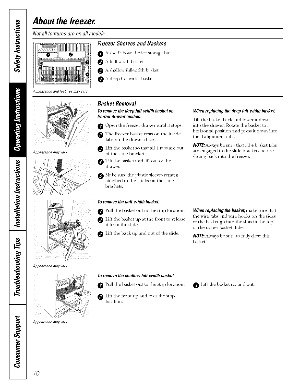
Freezer Shelves and Baskets
O A shelf above t]_e ice storage bh_
@ A ])_/]fL_vidth basket
0 A Sha]]o;_ fil]]-width basket
0 A deep _il]]-_vidt]) basket
Appearance and features may vary
Basket Removal
To remove the deep full-width basket on
freezer drawer models:
O Open the fl'eezer drawer until it stops.
@ The fl'eezer basket rests on the inside
_]b IJfl the basket so that all 4 tabs are out
Appearance may vary
v
tabs on the dra',ver slides.
of the slide bracket.
Tilt the basket and lift out of the
di'awei:
When replacing the deep full-width basket
Tilt the 1)asket back and lower it down
into the drawe_: Rotate the basket to a
horizoi_tal position and press it down into
the 4 aliglmmnt tabs.
NOTE:,M_):sbe sure that all 4 basket tabs
are engaged in the slide brackets betore
sliding back into the fl'eezex:
Appearance may vary
\
Appearance may vary
0 Make sure the plastic sleexes remain
attached to the 4 tabs on the slide
brackets.
To remove the half-width basket:
Pull the basket out to the stop location.
iJfi the basket up at the fl'ont to release
it fi'om the slides,
O iJfi the back up and out of the slide.
Toremove theshallow full-width basket:
Pull the basket out to the stop location.
iJfi the fl'ont up and oxer the stop
location.
When replacing the basket, make sure that
the wire tabs and wire hooks on the sides
ot the basket go into the slots in the top
ot the upper basket slides.
IVOTE:_Mwax:sbe sure to flfllv close this
basket.
0 Lift the basket up and out.
10
Abouttheautomaticicemaker, ge.cem
A newly installed refrigerator may take 12to 24 hours to begin making ice.
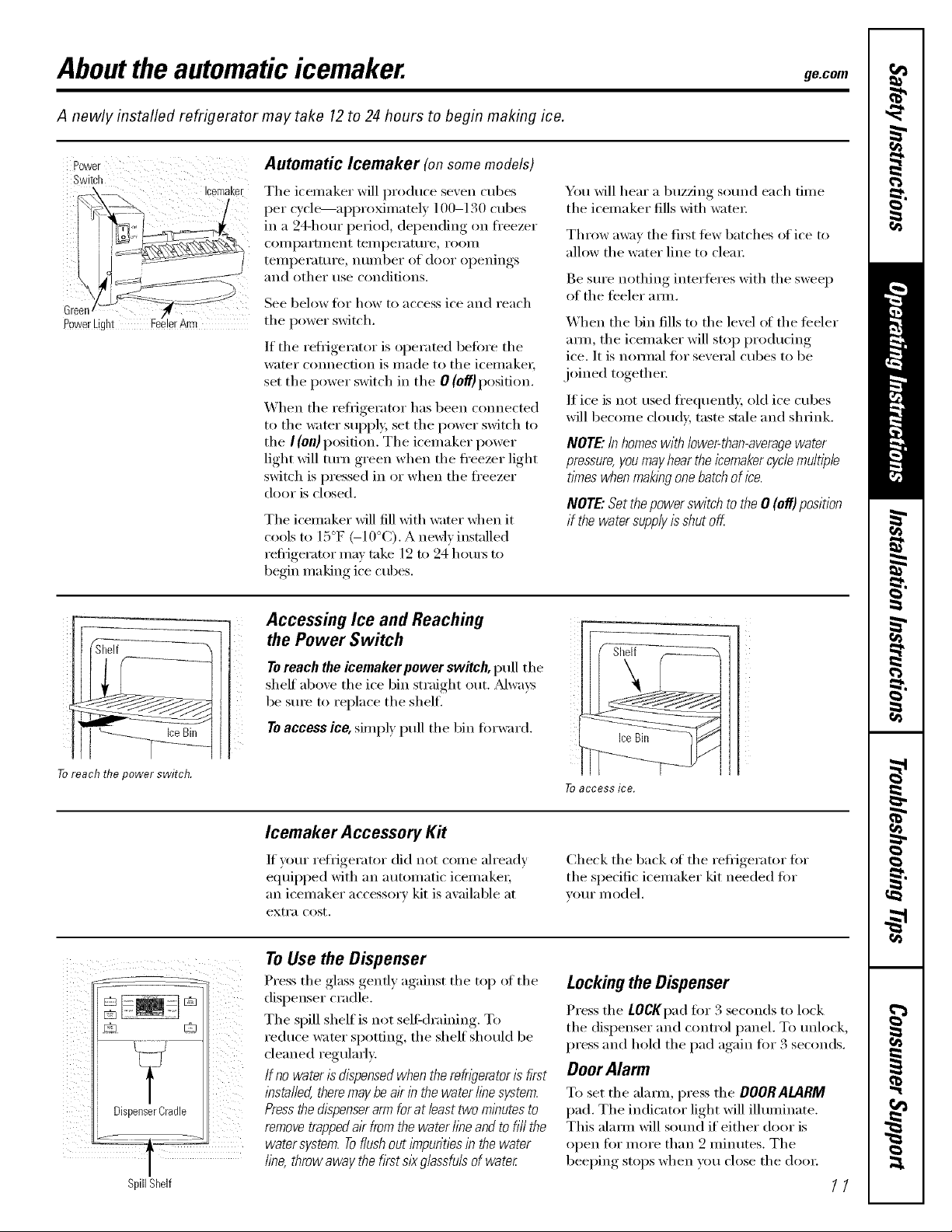
Power Automatic lcemaker (on some models)
Switch
L
_:e::'r/L':]'tc---'N,_,_eeer rm
The icemaker will produce seven cubes
per cycle---aI)I)rOxinmtely 100-130 cubes
in a 24-hour period, depending on fl'eezer
coil/pai'tlilent tei//pei'attli'e_ i'ooi//
temperature, number of door openings
and other use conditions.
See below fi)r how to access ice and reach
the power switch.
If the refl_igerator is operated befiwe the
water cmmection is made to the icemakei;
set the power switch in the 0 (eft) position.
When the refl-igerator has been connected
to the water supply, set the power switch to
the I (oil)position. The icemaker power
light will mrn green when the freezer light
switch is pressed in or when the fl'eezer
door is closed.
The icemaker Mll fill Mth water when it
cools to 15°F (-10°C). A newly installed
reflJgerator Ill}IV take ] 2 to 24 houÀ_ to
begin making ice cubes.
You Mll hear a buzzing sotmd each dine
the icemaker fills with watei:
Throw away the filSt tew batches of ice to
allow the water line to clem:
Be sm'e nothing interteres with the sweep
of the teeler amL
When the bin fills to the level ot the teeler
amL the icemaker will stop produdng
ice. It is i_olmal tor several cubes to be
.joined togethei:
If ice is not used fl'equenfl); old ice cubes
will become cloudy, taste stale and shrink.
NOTE"in homeswith lower-than-averagewater
pressure,you mayhear the icemakercycle multiple
times whenmaking onebatch ofice.
NOTE"Setthepowerswitchtothe0 (off)position
if the watersupplyisshutoff
Toreachthepowerswitch.
SpillShelf
Accessing Ice and Reaching
the Power Switch
Toreach the icemaker power switch, pull the
shelf" above the ice bin straight out. Mwa):s
be SUle to replace the shell
Toaccess ice, simply pull the bin torward.
Icemaker Accessory Kit
If your refYigerator did not colne ah'eadv
equipped with an automatic icemakeI;
an icemaker accessory kit is available at
exti'a cost,
To Use the Dispenser
Press the glass gently against the top of the
dispenser cradle.
The spill shelf is not sell:draining. To
reduce water spotting, the shelf should be
cleaned regularl>
If no water is dispensedwhen the refwerator is fkst
lbsta//ed,theremay beak in the water finesystem.
Pressthe dispenserarm forat least two minutes to
removetrappedair from the water fine andto fi// the
water system. Toflushout i_npuritiesin the water
fine, throw away the first slk glassfuls of water
To accessice,
Check the back of the refrigerator fiw
the specific icemaker kit needed tot
yore" model,
Locking the Dispenser
Press the LOCKpad fiw 3 seconds to lock
the dispenser and control panel. To unlock,
press and hoM the pad again fi)r 3 seconds.
OoorAlarm
To set the alamL press the DOORALARM
pad. The indicator light will ilhmfinate.
This alam_ will sotmd if' either door is
open for inore than 2 ininutes. The
beeping stops when you close the dooi:
11
Cleaning the Outside
The doorhandles and trim. Clean with a cloth
danq)ened with soapy water: Dry with a soft
cloth. Do not use wax on the door handles
and trim.
Keep the outside clean. Wipe Mth a clean
cloth lightly dampened Mth kitchen
appliance wax or miM liquid dish
detergent. Dry and polish with a clean,
soft cloth.
Donot wipetherefn_Teratorwith a soileddish
clothor wet towel. Thesemayleavea residue
that canerodethe paint.Donot usescouring
pads,powderedcleaners,bleachorcleaners
containingbleachbecausetheseproductscan
scratchand weakenthepaint finish.
Cleaning the Inside
The stainless steel panels and doorhandles.
Stainless steel (on some models) can be
cleaned with a commercially a\_lilable
stainless steel cleane_: A spray-(m stainless
steel cleaner w()rlcs best.
Do not use appliance wax or polish
on the stainless steel,
Silver-plated plastic parts. Wash parts Mth
soap or other mild detexgents. Wipe clean
with a sponge, damp cloth or paper towel.
Do not scrub with steel-wool pads or other
abrasive cleaners.
Tohelp prevent odors,leave an open box of
baking soda in the reli_igerator and ti'eezer
COIlll)_l I'tll/e nts,
Unplug the refrigerator before cleaning. If this
is not practical, wring excess moisture out
of sponge or cloth when cleaning around
switches, lights or controls.
Lrse an appliance wax polish on the inside
sm'lilce between the doo_.
Use warn/water and baking soda solution--
about a tablespoon (15 ml) of baking soda
to a quart (l liter) of water: This both cleans
and neutralizes odo_. Rinse and wipe dry.
Alter cleaning the door gaskets, apply a
thin laver of petroleum jelly to the door
gaskets at the hinge side. This helps kee I)
the gaskets fl'om sticking and bending out
ol shape.
Avoid cleaning cold glass shelves with hot water
because the extreme temperature difference may
cause them to ])real Handleglass she/yes
carefufl_zBumping tempered glass can cause
it to shatter
Donot washanyplasticrefngeratorpartsin
thedishwashe_
Silver-accented plastic parts. Wash parts
with soapy water: TVipe clean with a sponge,
damp cloth or paper towel.
Do not scrub with steel-wool pads or other
abrasive cleaners.
12
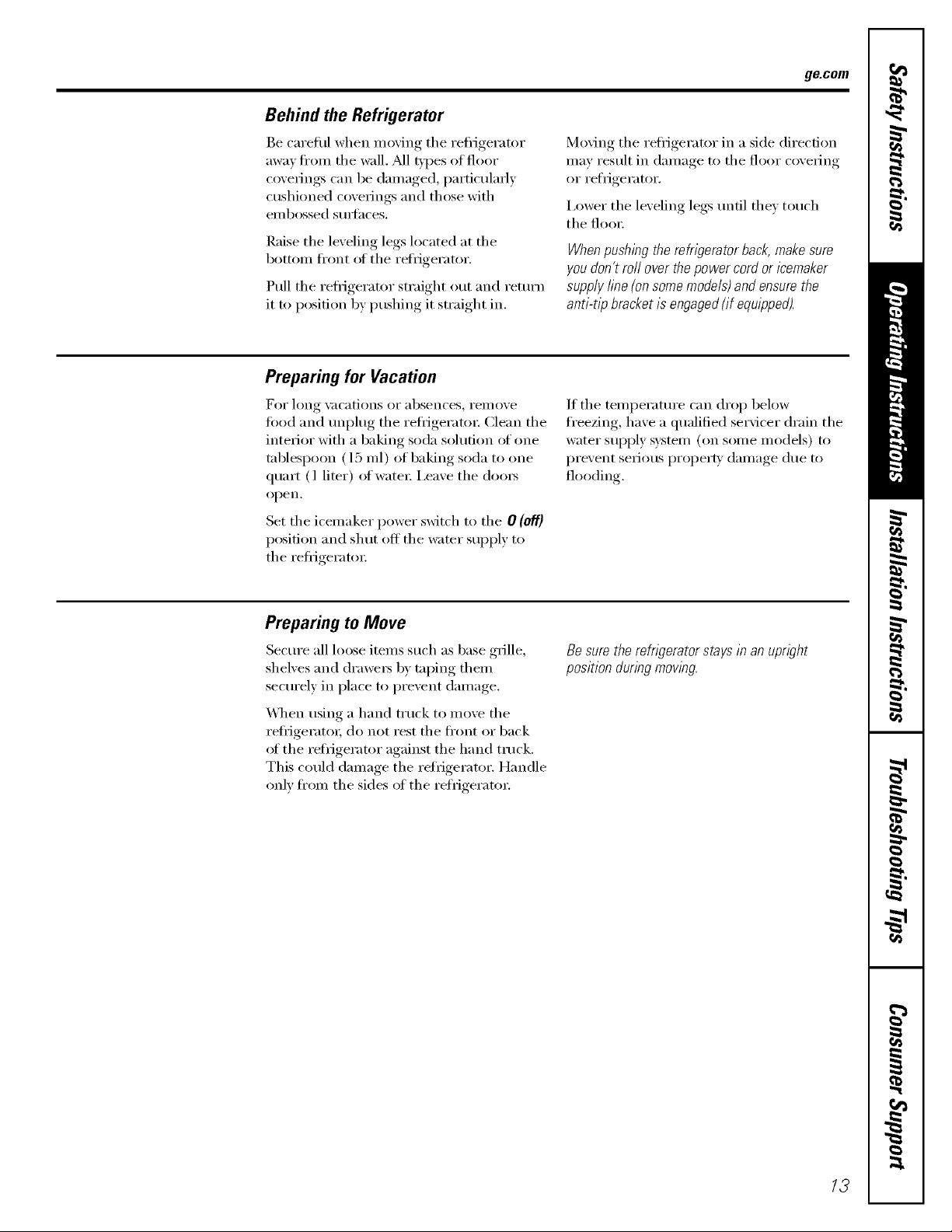
Behind the Refrigerator
Be careflfl when moving tile reti_igerator
away fl'om tile wall. M1 t,/pes of floor
coverings can be damaged, pa_licularly
cushioned coverings and those with
embossed S/lll'_lces.
Raise tile leveling legs located at tile
bottom fl'ont ot tile refrigerator.
Pull tile reflJgerator straight out and return
it to position by pushing it straight in.
Preparing for Vacation
g_com
Moving tile reflJgerator in a side direction
may result in damage to tile floor covering
or refrigerator.
I,ower tile leveling legs tmfil they touch
tile floo_:
When pushing the refrigerator back, make sure
you don't roll over the power cord or icemaker
supply fine {on some models) and ensure the
anti-tli9 bracket is engaged(if equligped).
For long \;l(-ations or absen(-es_ i'ell/OVe
food aim Ulq)lug tile reflJgeratoi: Clean tile
interior with a baking soda solution of one
tablespoon (15 ml) of baking soda to one
quart (l liter) of water: i,eave tile cloo_
ol)en.
Set the icemaker power switch to the 0 (o1_}
position and shut off tile water supply to
the refl_igeratm:
Preparing to Move
Secure all loose items such as base grille,
shelves and drawe_ by taping them
securely in place to prevent damage.
\_]/en using a hand truck to move tile
reti_igerato_; do not rest tile front or back
ot the reti_igerator against the hand truck.
This could damage the reti_igeramr. Handle
only fl'om the sides ot the reti_igeratm:
If the temperature can drop below
fl'eezing, have a qualified servicer drain the
water supply system (on some models) to
prevent serious proper b' damage due to
flooding.
Besurethe refrigeratorstaysin anupright
positionduringmoving.
13
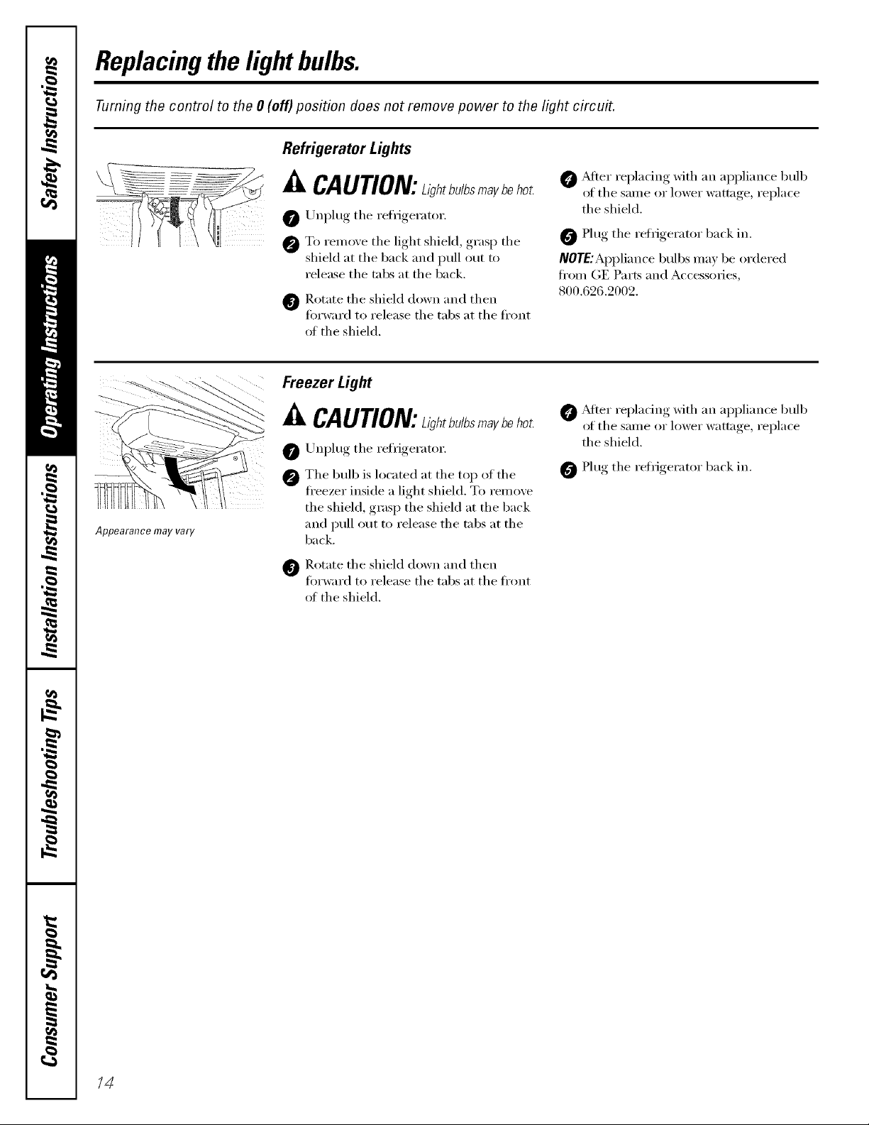
Replacingthe lightbulbs.
Turning the control to the 0 (off) position does not remove power to the light circuit.
Refrigerator Lights
Appearance may vary
_i, CAUTION:ahtb./bsmaybeho_
0 Unplug the refrigerator.
To remove tile light shieM, grasp tile
shield at tile back and pull out to
release tile tabs at tile back.
Rotate tile shield down and then
torward to release tile tabs at tile fl'ont
oI tile shield.
Freezer Light
A CAUTION:L/_htb./bsma_beho_
Unplug tile refrigerator.
The bulb is located at tile top of tile
fl'eezer inside a light shield. To remove
the shield, grasp the shield at the back
and pull out to release tile tabs at tile
back.
_]b Rotate tile shield down and then
fin'ward to release tile tabs at tile fl'ont
of the shield.
@ _dtei" replacing with an appliance bulb
of the same or lower wattage, replace
the shield.
0 Plug tile refrigerator back in.
IVOTE:Appliai,_ce bulbs ma_ be ordered
fl'om (;E Parts and Accessories,
800.626.2002.
_Mter replacing with an appliance bulb
of tile same or lower wattage, replace
the shield.
0 Plug tile refrigerator back in.
/4
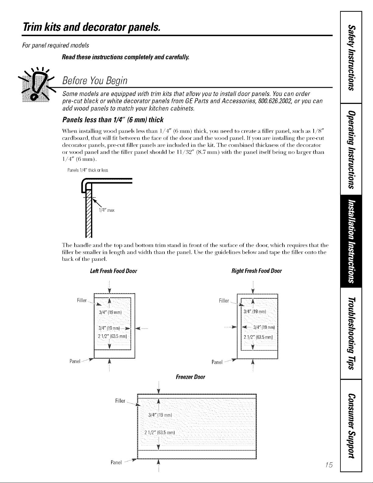
Trimkits and decoratorpanels.
For panel required models
Read these instructionscompletely and carefully.
Before YouBegin
Some models are equipped with trim kits that aflow you to install door panels. Youcan order
pre-cut black or white decorator panels from GE Parts and Accessories, 800.626.2002, or you can
add wood panels to match your kitchen cabinets.
Panels less than 1/4" (6mm) thick
_,_]_en installing wood panels less than ]/4" (6 ram) thick, you need to create a filler panel, such as 1/8"
cardboard, that will fit between the face (4 the door and the wood panel. If you are installing the we-cut
decorator panels, i)re-cut filler panels are included in the kit. The combined thickness of the decorator
or wood panel and the filler panel should be 11/32" (8.7 ram) with the panel itself being no larger than
1/4" (6 ram).
Panels1/4"thickoriess
1/4" max
The handle and the top and bottom tcim stand in front of the surii_ce of the do()); which requires that the
filler be smaller in lenoth_ and width than the panel. Use the gtfidelines below and tape the filler onto the
back of the panel.
LeftFreshFoodDoor
J
RightFreshFoodDoor
V
Filler
3/4" 19mm
3/4" (19turn)
2 1/2" 63.5rnm
!
Filler _"A,--
3/4" (!9 mrn)
-_' _, 3/4"(19mm)
iii"ii_s,,m)
i
V
Panel '_ _
FreezerDoor
Panel "_ ,&
Fi,,er.... ili!I¸!?d¸/ ; :;£
Panel _ /5

Trimkits anddecoratorpanels.
3/4" (19mm) or Raised Panel
A raised panel design screwed or glued to a ]/4" (6 ram) thick backing, or a 3/4" (]9 ram) routed board
can be used. The raised portion of the panel must be tid)_icated to pemfit clearances of at least 2" (5.1 cm)
fl'om the handle side flw fingertip clearance.
Panels thicker than 1/4" (6 ram), up to 3/4" (19 ram) max., will require that the outer 5/16" (8 ram) oI
panel perimeter be no thicker than 1/4" (6 ram),
Weightlimitationsfor custompanels:
FreshFood10Ibs.(4.5kg)max.for eachdoor
FreezerDoor 18Ibs.(8kg)max.
Pan@thickerthan1/4" (6rand
1/4"(6 mm)
ThickBacking
16"(8 mm)
1/4" (6Into)max
3/4" (19ram)
Dimensions for Custom Wood Panels
5/16" (8 ram)
minimumat
1/4" (6mm)
thickness
Top,left and
bottom
Raisedportion_f
of panel
LeftFreshFoodDoor
isram>--I I_'",
,,_ 2'_ (51 mini
thickness
28 15/16"
(73.5cm)
2"(5.1 cm)
Clearance
HandleSide
Appearance
Panel
1/8........ .
/
mlnlleule at
1/4" (6 mm/
Handleside
r
(6m[e}
. ..... 1/8"
,,q l 19ram>
I
"1/4" [_7 /' "
(6ram)_::_ ........
2" (51 mm)
minimumat
1/4" (6 ram)
thickness
Handleside
Raisedportion
of panel
(19mm)
Refrigerator
Door
RightFreshFoodDoor
iJ
t
5/16" (8 mm)
minimumat
1/4" (6 ram)
thickness
Top,left and
bottom
2815/16"
(73.5cm)
16
1629/32" (42.9cm)
5/16" (8 ram)minimum
at 1/4" (6ram)thickness
Left,right and .
bottomsides Ras.ed
k ?_. 1/8"
q /
2" (51 ram)minimumat
1/4" (6ram)thickness
Handleside
J
r
"i'/4" _1I_ti
(6 ram)...... "
portion
ofpanel
/"
1/8" .....
(3 ram)
" --(6 ram)
_L
1
Freezer Door
1/6" " - i_,:_,
(9mm) | ',
"',.LI I_ 1/4;/
"" .... (6 ram)
I / .... "-1/8"
L-_
/
1629/32" (42.9cm)
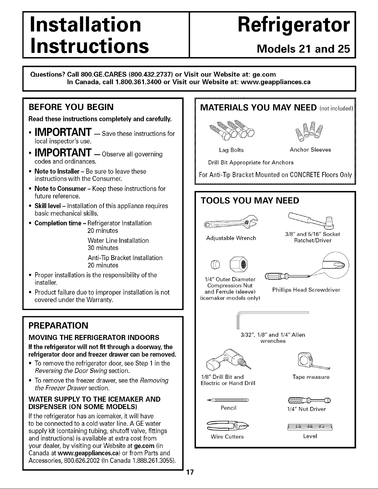
Installation
Refrigerator
Instructions
Questions? Call 800.GE.CARES (800.432.2737) or Visit our Website at: ge.com
I
BEFORE YOU BEGIN
Read these instructions completely and carefully.
• IMPORTANT- Save these instructions for
local inspector's use.
• IMPORTANT- Observeallgoverning
codes and ordinances.
• Note to Installer- Be sure to leave these
instructions with the Consumer.
• Note to Consumer- Keep these instructions for
future reference.
• Skill level- Installation of this appliance requires
basic mechanical skills.
• Completion time - Refrigerator Installation
In Canada, call 1.800.361.3400 or Visit our Website at: www.geappliances.ca
MATERIALS YOU MAY NEED (not included)
Lag Bolts Anchor Sleeves
Drill Bit Appropriate for Anchors
For Anti-lip Bracket Mounted on CONCRETEFloors 0nly
TOOLS YOU MAY NEED
20 minutes
Water Line Installation
30 minutes
Adjustable Wrench Ratchet/Driver
Models 21 and 25
I
3/8" and 5/16" Socket
Anti--[]p Bracket Installation
20 minutes
• Proper installation is the responsibility of the
installer.
• Product failure due to improper installation is not
covered under the Warranty.
PREPARATION
MOVING THE REFRIGERATOR INDOORS
If the refrigerator will not fit through a doorway, the
refrigerator door and freezer drawer can be removed.
• To remove the refrigerator door, see Step 1 in the
Reversing the Door Swing section.
• To remove the freezer drawer, see the Removing
the Freezer Drawer section.
WATER SUPPLY TO THE ICEMAKER AND
DISPENSER (ON SOME MODELS)
If the refrigerator has an icemaker, it will have
to be connected to a cold water line. AGE water
supply kit (containing tubing, shutoff valve, fittings
and instructions) is available at extra cost from
your dealer, by visiting our Website at ge.com (in
Canada at www.geappliances.ca) or from Parts and
Accessories, 800.626.2002 (In Canada 1.888.261.3055).
1/4" Outer Diameter
Compression Nut
and Ferrule (sleeve)
(icemaker models only)
3/32", 1/8" and 1/4"Allen
1/8" Drill Bit and
Electric or Hand Drill
Pencil
Wire Cutters
Phillips Head Screwdriver
wrenches
Tape measure
1/4" Nut Driver
Level
17
Installation Instructions
INSTALLING THE ANTI-TIP FLOOR BRACKET (on 21 ft. models)
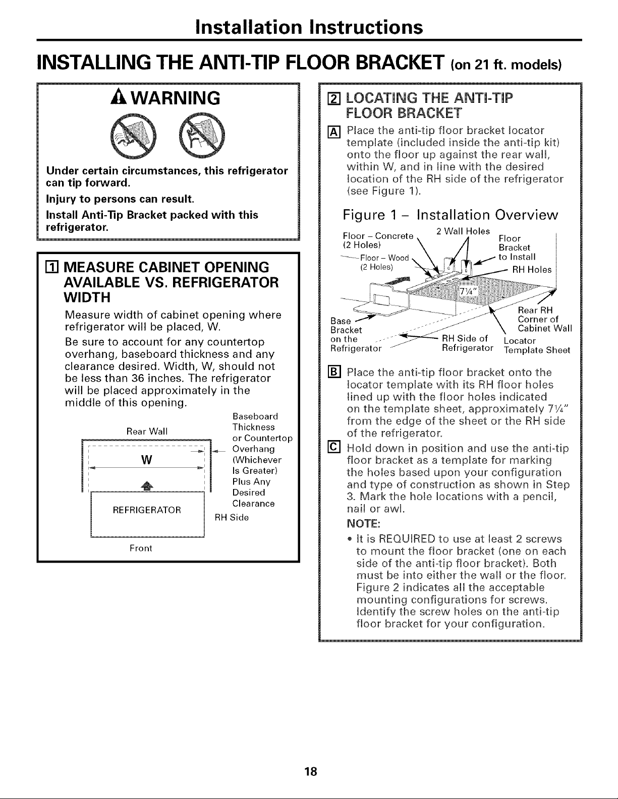
WARNING
Under certain circumstances, this refrigerator
can tip forward,
Injury to persons can result,
Install Anti-Tip Bracket packed with this
refrigerator,
[] MEASURE CABINET OPENING
AVAILABLE VS. REFRIGERATOR
WIDTH
Measure width of cabinet opening where
refrigerator will be placed, W.
Be sure to account for any countertop
overhang, baseboard thickness and any
clearance desired. Width, W, should not
be less than 36 inches. The refrigerator
will be placed approximately in the
middle of this opening.
Baseboard
Thickness
or Countertop
Overhang
(Whichever
Is Greater)
Plus Any
Desired
Clearance
RH Side
I
i
I
REFRIGERATOR
i
Rear Wall
W _'
_1, 1+'-
Front
[] LOCATING THE ANTI-TIP
FLOOR BRACKET
Place the anti=tip floor bracket locator
[]
template dnchJded inside the antVtip kit)
onto the floor up against the rear wall,
within W, and in line with the desired
location of the RH side of the refrigerator
(see Figure 1).
Figure 1 - Installation Overview
Floor - Concrete 2 Wall Holes
(2 Holes) Bracket
_-_-Floor - Wood to Install
(2 Holes) RH Holes
Base ._--f_ Corner of
Bracket Cabinet Wall
on the f"_ RH Side of Locator
Refrigerator / Refrigerator Template Sheet
[] Place the anti=tip floor bracket onto the
tocator template with its RH floor holes
lined up with the floor holes indicated
on the template sheet, approximately 71/4"
from the edge of the sheet or the RH side
of the refrigerator.
[] Hold down in position and use the anti=tip
floor bracket as a template for marking
the holes based upon your configuration
and type of construction as shown in Step
3. Mark the hole locations with a pencil,
nail or awl.
NOTE:
tt isREQUIRED to use at least 2 screws
to mount the floor bracket (one on each
side of the anti4ip floor bracket). Both
must be into either the wall or the floor.
Figure 2 indicates all the acceptable
mounting configurations for screws.
Identify the screw holes on the anti tip
floor bracket for your configuration.
Floor
Rear RH
18
mnstaliation mnstructions
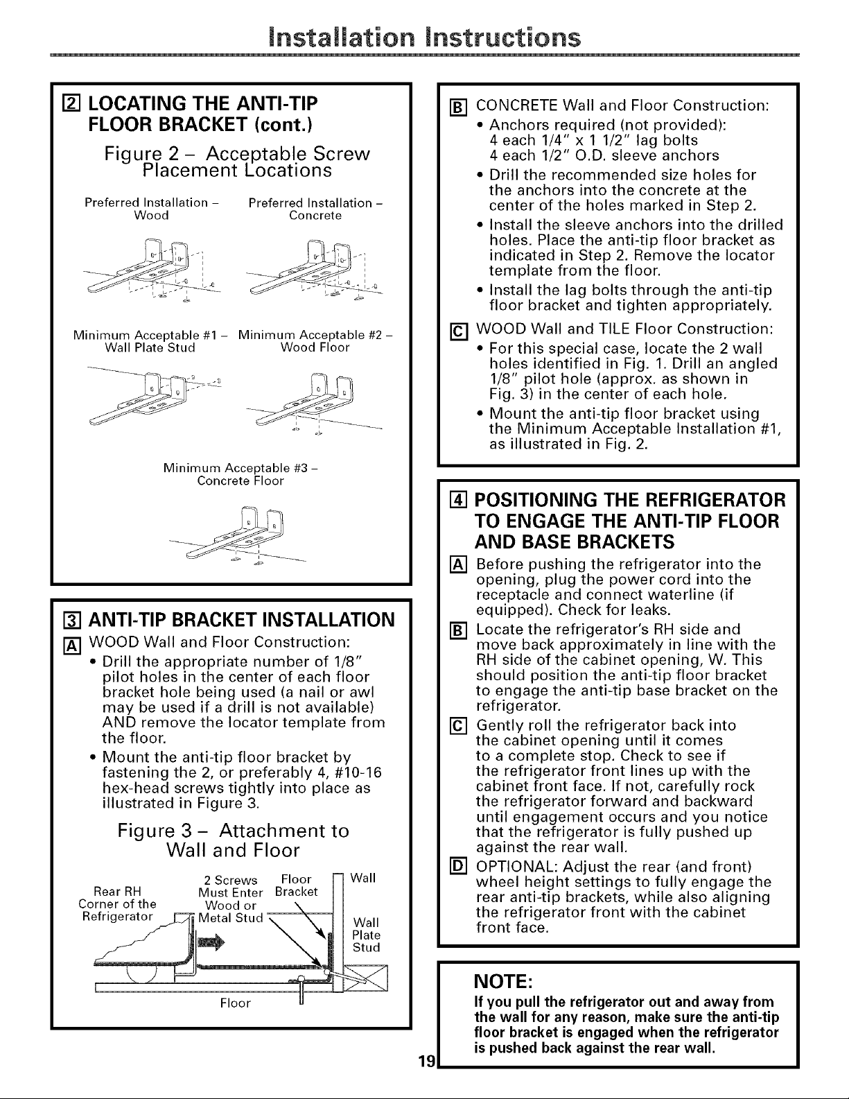
[] LOCATING THE ANTI-TIP
FLOOR BRACKET (cont.)
Figure 2 - Acce.ptable Screw
Placement Locations
Preferred Installation -
Minimum Acceptable #1- Minimum Acceptable #2-
Wood
Wall Plate Stud Wood Floor
Minimum Acceptable #3 -
Concrete Floor
Preferred Installation-
Concrete
[] ANTI-TIP BRACKET INSTALLATION
[] WOOD Wall and Floor Construction:
• Drill the appropriate number of 1/8"
pilot holes in the center of each floor
bracket hole being used (a nail or awl
may be used if a drill is not available)
AND remove the Iocator template from
the floor.
• Mount the anti-tip floor bracket by
fastening the 2, or preferably 4, #10-16
hex-head screws tightly into place as
illustrated in Figure 3.
Figure 3- Attachment to
Wall and Floor
2 Screws Floor [=1Wall
RearRH Must Enter Bracket H
Corner of the Wood or \ I H
Refngerator_C;_ Metal Stud _ I Wall
_f l_l_ _ %_ I Plate
\ mMStud
[] CONCRETE Wall and Floor Construction:
• Anchors required (not provided):
4 each 1/4" x 1 1/2" lag bolts
4 each 1/2" O.D. sleeve anchors
• Drill the recommended size holes for
the anchors into the concrete at the
center of the holes marked in Step 2.
• Install the sleeve anchors into the drilled
holes. Place the anti-tip floor bracket as
indicated in Step 2. Remove the Iocator
template from the floor.
• Install the lag bolts through the anti-tip
floor bracket and tighten appropriately.
[] WOOD Wall and TILE Floor Construction:
• For this special case, locate the 2 wall
holes identified in Fig. 1. Drill an angled
1/8" pilot hole (approx. as shown in
Fig. 3) in the center of each hole.
• Mount the anti-tip floor bracket using
the Minimum Acceptable Installation #1,
as illustrated in Fig. 2.
[] POSITIONING THE REFRIGERATOR
TO ENGAGE THE ANTI-TIP FLOOR
AND BASE BRACKETS
[] Before pushing the refrigerator into the
opening, plug the power cord into the
receptacle and connect waterline (if
equipped). Check for leaks.
[] Locate the refrigerator's RH side and
move back approximately in line with the
RH side of the cabinet opening, W. This
should position the anti-tip floor bracket
to engage the anti-tip base bracket on the
refrigerator.
[] Gently roll the refrigerator back into
the cabinet opening until it comes
to a complete stop. Check to see if
the refrigerator front lines up with the
cabinet front face. If not, carefully rock
the refrigerator forward and backward
until engagement occurs and you notice
that the refrigerator is fully pushed up
against the rear wall.
[] OPTIONAL: Adjust the rear (and front)
wheel height settings to fully engage the
rear anti-tip brackets, while also aligning
the refrigerator front with the cabinet
front face.
Floor [J
NOTE:
If you pull the refrigerator out and away from
the wall for any reason, make sure the anti-tip
floor bracket is engaged when the refrigerator
is pushed back against the rear wall.
19
mnstaliation mnstructions
INSTALLING THE REFRIGERATOR
REFRIGERATOR LOCATION
• Do not install the refrigerator where the
temperature will go below 60°F (16°C) because it
will not run often enough to maintain proper
temperatures.
• Do not install the refrigerator where the
temperature will go above 100°F (37°C) because it
will not perform properly.
• Install it on a floor strong enough to support it fully
loaded.
CLEARANCES
Allow the following clearances for ease of installation,
proper air circulation and plumbing and electrical
connections.
Standard Depth Counter Depth
Models Models
Sides 1/8" (3 mm) 1/8" (3 mm)
Top 1" (25 mm) 1" (25 mm)
Back 1" (25 mm) 1/2" (13 mm)
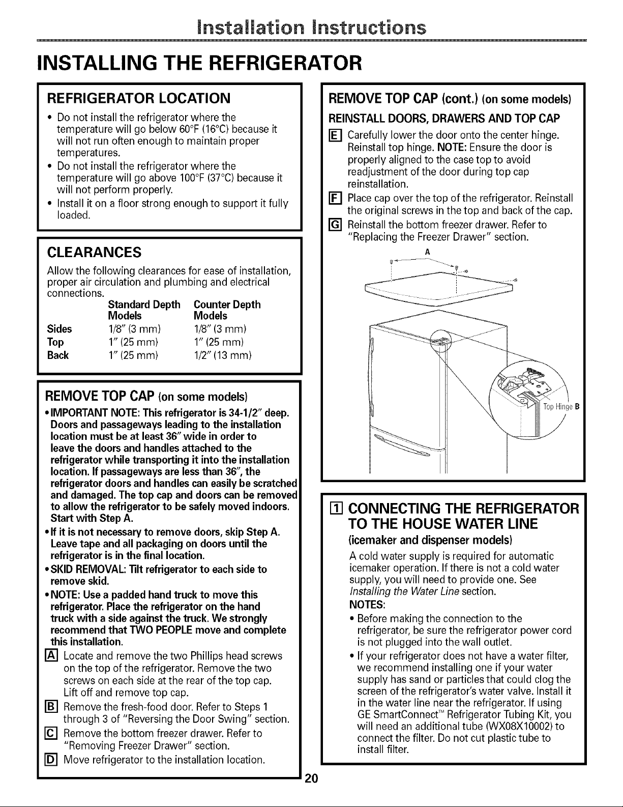
REMOVE TOP CAP (cont.) (onsomemodels)
REINSTALL DOORS, DRAWERS AND TOP CAP
[] Carefully lower the door onto the center hinge.
Reinstall top hinge. NOTE: Ensure the door is
properly aligned to the case top to avoid
readjustment of the door during top cap
reinstallation.
[] Place cap over the top of the refrigerator. Reinstall
the original screws in the top and back of the cap.
[] Reinstall the bottom freezer drawer. Refer to
"Replacing the Freezer Drawer" section.
A
.... o
REMOVE TOP CAP (onsomemodels)
• IMPORTANT NOTE: This refrigerator is34-1/2" deep.
Doors and passageways leading to the installation
location must be at least 36" wide in order to
leave the doors and handles attached to the
refrigerator while transporting it into the installation
location. If passageways are lessthan 36",the
refrigerator doors and handles can easily be scratched
and damaged. The top cap and doors can be removed
to allow the refrigerator to be safely moved indoors.
Start with Step A.
• If it is not necessary to remove doors, skip Step A.
Leave tape and all packaging on doors until the
refrigerator is in the final location.
• SKID REMOVAL: ]ilt refrigerator to each side to
remove skid.
• NOTE: Use a padded hand truck to move this
refrigerator. Place the refrigerator on the hand
truck with a side against the truck. We strongly
recommend that TWO PEOPLE move and complete
this installation.
[] Locate and remove the two Phillips head screws
on the top of the refrigerator. Remove the two
screws on each side at the rear of the top cap.
Lift off and remove top cap.
[] Remove the fresh-food door. Refer to Steps 1
through 3 of "Reversing the Door Swing" section.
[] Remove the bottom freezer drawer. Refer to
"Removing Freezer Drawer" section.
[] Move refrigerator to the installation location.
TopHingeB
[] CONNECTING THE REFRIGERATOR
TO THE HOUSE WATER LINE
(icemaker and dispenser models)
A cold water supply is required for automatic
icemaker operation. If there is not a cold water
supply, you will need to provide one. See
Installing the Water Line section.
NOTES:
• Before making the connection to the
refrigerator, be sure the refrigerator power cord
is not plugged into the wall outlet.
• If your refrigerator does not have a water filter,
we recommend installing one if your water
supply has sand or particles that could clog the
screen of the refrigerator's water valve. Install it
in the water line near the refrigerator. If using
GE SmartConnect TM Refrigerator Tubing Kit, you
will need an additional tube (WX08XIO002) to
connect the filter. Do not cut plastic tube to
install filter.
20
Installation Instructions
[] CONNECTING THE REFRIGERATOR
TO THE HOUSE WATER LINE
(cont.)
[] If you are using copper tubing, place a
compression nut and ferrule (sleeve) onto
the end of the tubing coming from the
house cold water supply.
If you are using the GE SmartConnect TM
tubing, the nuts are already assembled to
the tubing.
[] If you are using copper tubing, insert
the end of the tubing into the refrigerator
connection, at the back of the refrigerator,
as far as possible, While holding the
tubing, tighten the fitting,
If you are using GE SmartConnect TM
tubing, insert the molded end of the
tubing into the refrigerator connection,
at the back of the refrigerator, and tighten
the compression nut until it is hand tight.
Then tighten one additional turn with a
wrench. Overtightening may cause leaks.
[] Fasten the tubing into the clamp provided
to hold it in position, You may need to pry
open the clamp.
[] TURN ON THE WATER SUPPLY
(icemaker and dispenser models)
Turn the water on at the shutoff valve (house
water supply) and check for any leaks.
[] PLUG IN THE REFRIGERATOR
On models with an icemaker, before plugging in
the refrigerator, make sure the icemaker power
switch is set to the O (off) position.
See the grounding information attached to the
power cord.
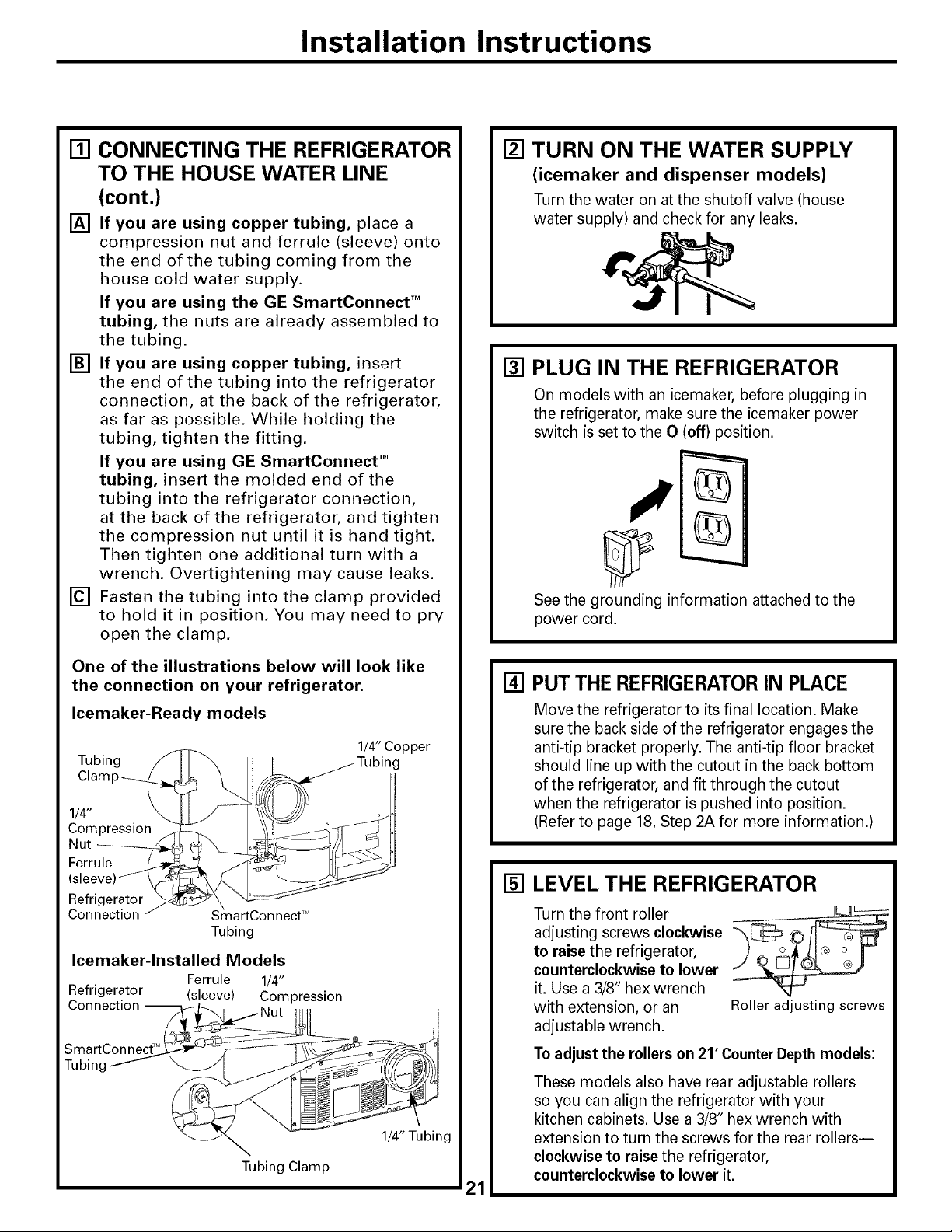
One of the illustrations below will look like
the connection on your refrigerator.
Icemaker-Ready models
Tubing
1/4"
Compression
Nut
Ferrule
Refrigerator
Connection
Icemaker-lnstalled Models
Refrigerator (sleeve) Compression
Connection --
Tubin£
SmartConnect TM
Tubing
Ferrule 1/4"
Tubing Clamp
1/4" Copper
1/4" Tubing
[] PUT THE REFRIGERATORIN PLACE
Move the refrigerator to its final location. Make
sure the back side of the refrigerator engages the
anti-tip bracket properly. The anti-tip floor bracket
should line up with the cutout in the back bottom
of the refrigerator, and fit through the cutout
when the refrigerator is pushed into position.
(Refer to page 18, Step 2A for more information.)
[] LEVEL THE REFRIGERATOR
Turn the front roller
adjusting screws clockwise
to raise the refrigerator,
counterclockwise to lower
it. Use a 3/8" hex wrench
with extension, or an Roller adjusting screws
adjustable wrench.
To adjust the rollers on 21' Counter Depth models:
These models also have rear adjustable rollers
so you can align the refrigerator with your
kitchen cabinets. Use a 3/8" hex wrench with
extension to turn the screws for the rear rollers--
clockwise to raise the refrigerator,
counterclockwise to lower it.
21
mnstaliation mnstructions
INSTALLING THE REFRIGERATOR (cont.)
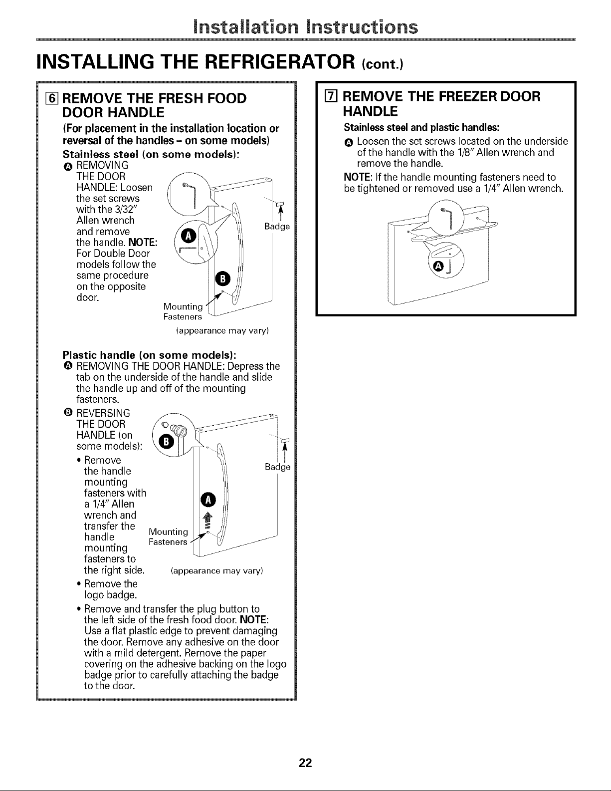
[] REMOVE THE FRESH FOOD
DOOR HANDLE
(For placement in the installation location or
reversal of the handles - on some models
Stainless steel (on some models):
O REMOVING
THE DOOR
HANDLE: Loosen
the set screws
with the 3/32"
Allen wrench
and remove Badge
the handle. NOTE:
For Double Door
models follow the
same procedure
on the opposite
door.
Mounting
Fasteners
(appearance may vary)
Plastic handle (on some models):
REMOVING THE DOOR HANDLE: Depress the
tab on the underside of the handle and slide
the handle up and off of the mounting
fasteners.
Q REVERSING
THE DOOR
[] REMOVE THE FREEZER DOOR
HANDLE
Stainless steel and plastic handles:
Q Loosen the set screws located on the underside
of the handle with the 1/8"Allen wrench and
remove the handle.
NOTE: If the handle mounting fasteners need to
be tightened or removed use a 1/4" Allen wrench.
some models):
* Remove
the handle
mounting
fasteners with
a 1/4"Allen
wrench and
transfer the
handle Mounting
mounting
fasteners to
the right side. (appearance may vary)
" Remove the
logo badge.
, Remove and transfer the plug button to
the left side of the fresh food door. NOTE:
Use a flat plastic edge to prevent damaging
the door. Remove any adhesive on the door
with a mild detergent. Remove the paper
covering on the adhesive backing on the logo
badge prior to carefully attaching the badge
to the door.
Fasteners.
22
Installation Instructions
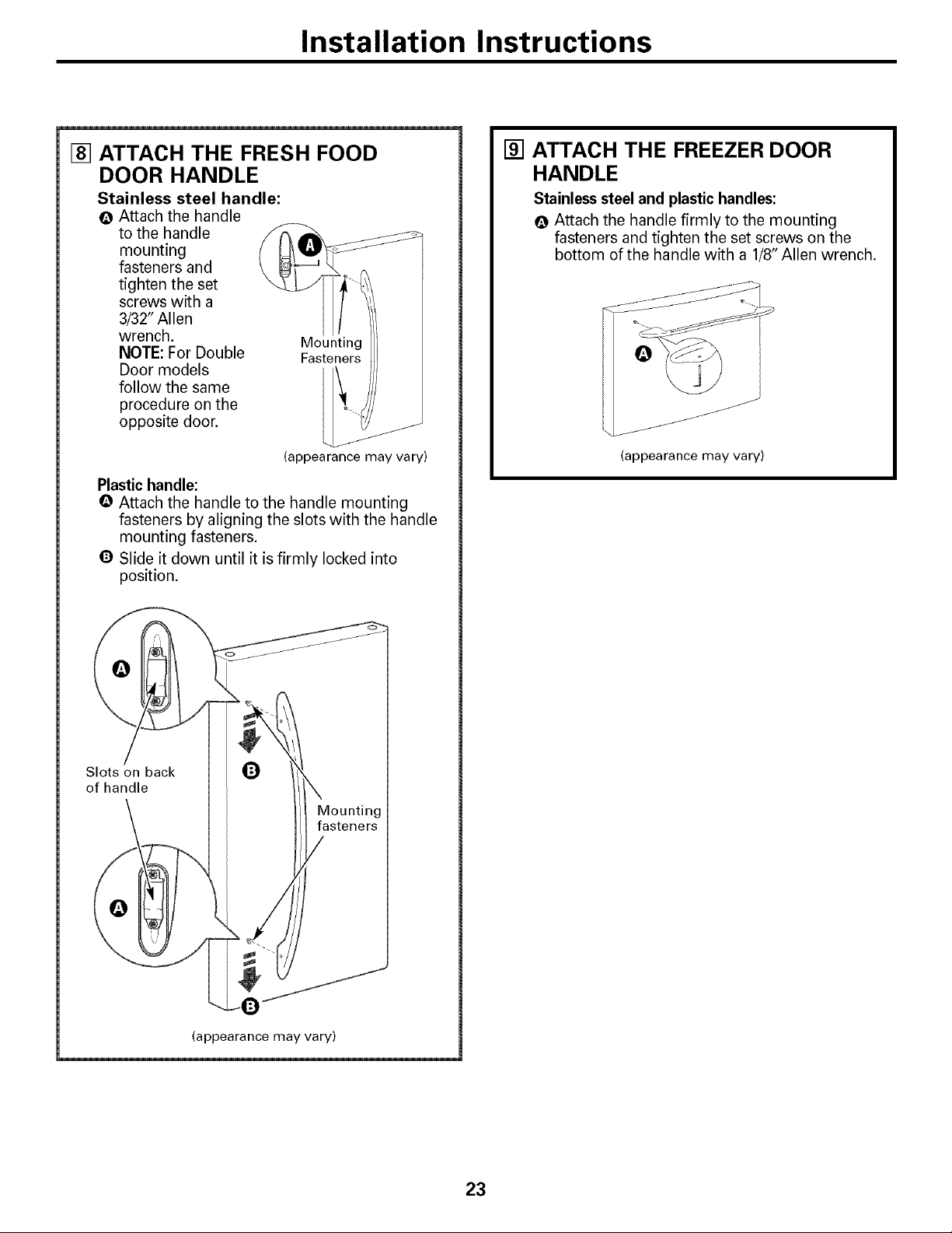
[] ATTACH THE FRESH FOOD
DOOR HANDLE
Stainless steel handle:
Attach the handle
to the handle
mounting
fasteners and
tighten the set
screws with a
3/32" Allen
wrench. Mounting
NOTE: For Double Fasteners
Door models
follow the same
procedure on the
opposite door.
(appearance may vary)
Plastic handle:
Q Attach the handle to the handle mounting
fasteners by aligning the slots with the handle
mounting fasteners.
Q Slide it down until it is firmly locked into
position.
[] ATTACH THE FREEZER DOOR
HANDLE
Stainless steel and plastic handles:
Q Attach the handle firmly to the mounting
fasteners and tighten the set screws on the
bottom of the handle with a 1/8" Allen wrench.
(appearance may vary)
Slots on back
of handle
O
Mounting
fasteners
(appearance may vary)
23
Installation Instructions
INSTALLING THE REFRIGERATOR (cont,)
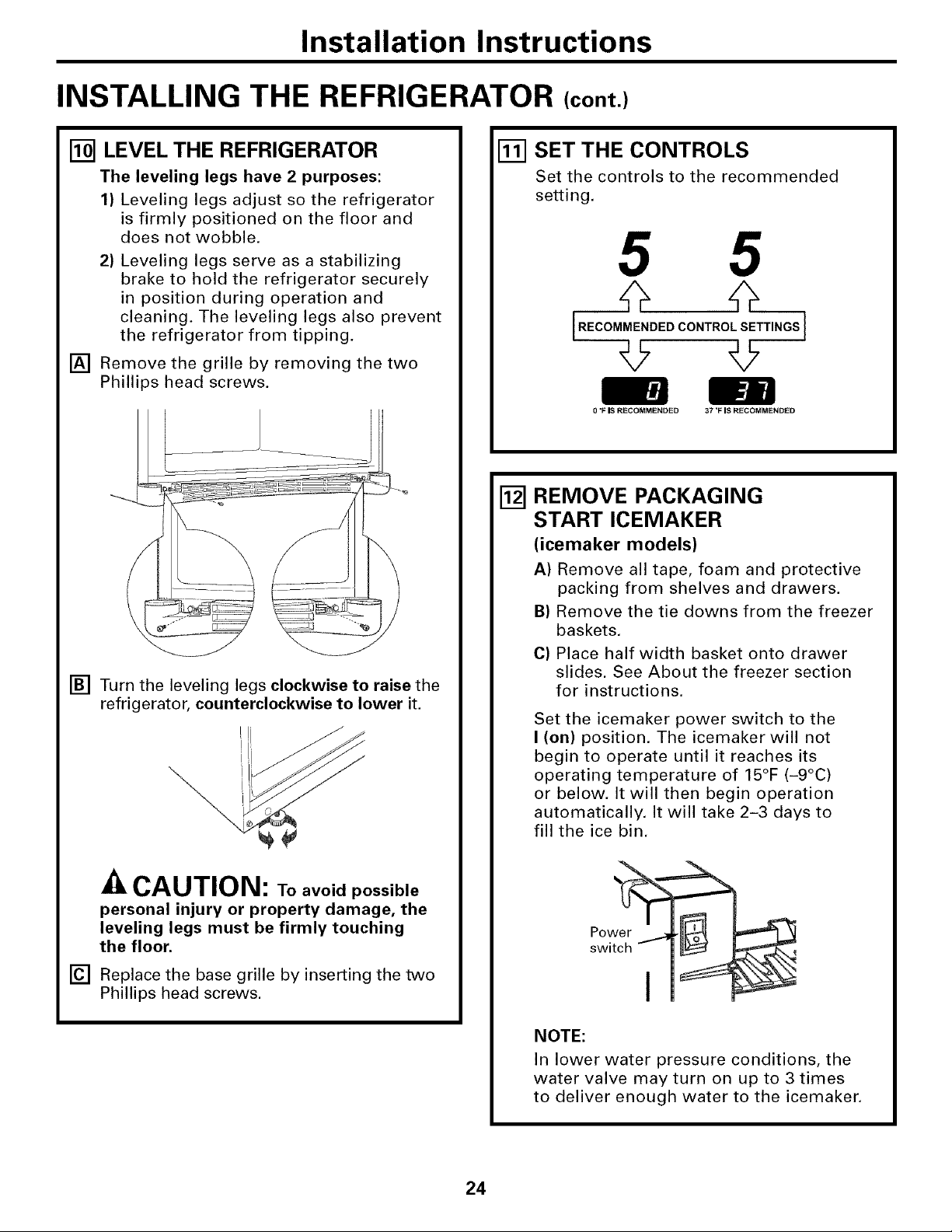
I_] LEVEL THE REFRIGERATOR
The leveling legs have 2 purposes:
1) Leveling legs adjust so the refrigerator
is firmly positioned on the floor and
does not wobble.
2) Leveling legs serve as a stabilizing
brake to hold the refrigerator securely
in position during operation and
cleaning. The leveling legs also prevent
the refrigerator from tipping.
[] Remove the grille by removing the two
Phillips head screws.
[] Turn the leveling legs clockwise to raise the
refrigerator, counterclockwise to lower it.
[] SET THE CONTROLS
Set the controls to the recommended
setting.
h
liJ
0 "FIS RECOMMENDED 37'F IS RECOMMENDED
REMOVE PACKAGING
[]
START ICEMAKER
(icemaker models)
A) Remove all tape, foam and protective
packing from shelves and drawers.
B) Remove the tie downs from the freezer
baskets.
C) Place half width basket onto drawer
slides. See About the freezer section
for instructions.
Set the icemaker power switch to the
I (on) position. The icemaker will not
begin to operate until it reaches its
operating temperature of 150F (-9oc)
or below. It will then begin operation
automatically. It will take 2-3 days to
fill the ice bin.
CAUTION: Toavoidpossible
personal injury or property damage, the
leveling legs must be firmly touching
the floor.
[] Replace the base grille by inserting the two
Phillips head screws.
NOTE:
In lower water pressure conditions, the
water valve may turn on up to 3 times
to deliver enough water to the icemaker.
24
mnstaliation mnstructions
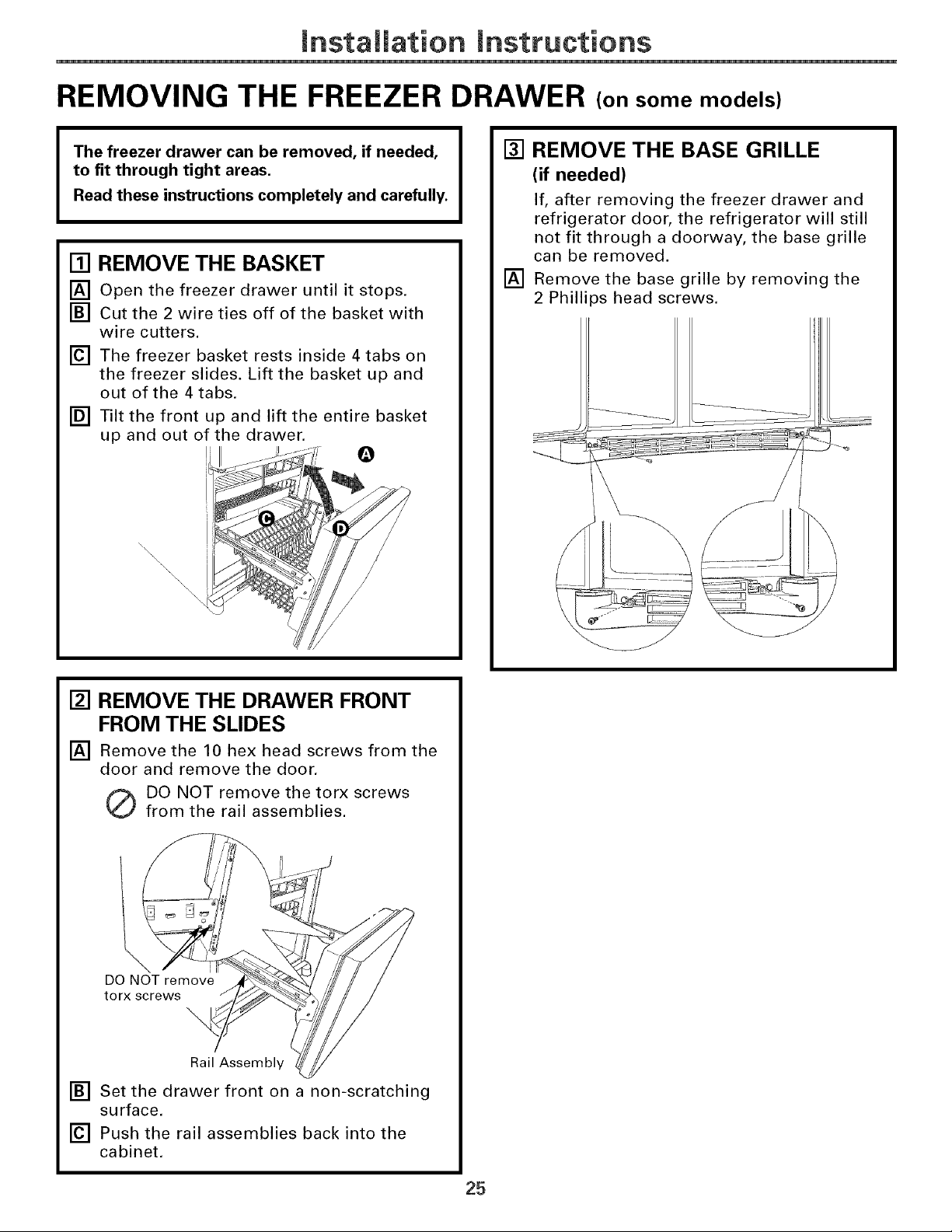
REMOVING THE FREEZER DRAWER (on some models)
The freezer drawer can be removed, if needed,
to fit through tight areas.
Read these instructions completely and carefully.
[] REMOVE THE BASKET
[] Open the freezer drawer until it stops.
[] Cut the 2 wire ties off of the basket with
wire cutters.
[] The freezer basket rests inside 4 tabs on
the freezer slides. Lift the basket up and
out of the 4 tabs.
[] Tilt the front up and lift the entire basket
up and out of the drawer.
Q
\\\\
[] REMOVE THE BASE GRILLE
(if needed)
If, after removing the freezer drawer and
refrigerator door, the refrigerator will still
not fit through a doorway, the base grille
can be removed.
[] Remove the base grille by removing the
2 Phillips head screws.
[] REMOVE THE DRAWER FRONT
FROM THE SLIDES
[] Remove the 10 hex head screws from the
door and remove the door.
Q DO NOT remove the torx screws
from the rail assemblies.
\
DO NOT remove
torx screws
-.,
Rail Assembly
[] Set the drawer front non-scratching
surface.
[] Push the rail assemblies back into the
cabinet.
on a
25
mnstaliation mnstructions
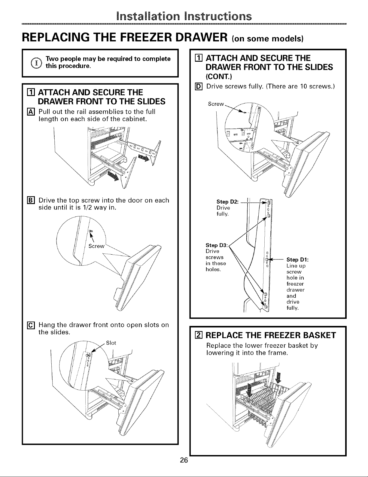
REPLACING THE FREEZER DRAWER (on some models)
o Two people may be required to complete
I
this procedure.
[] ATTACH AND SECURE THE
DRAWER FRONT TO THE SLIDES
[] Pull out the rail assemblies to the full
length on each side of the cabinet.
[] Drive the top screw into the door on each
side until it is 1/2 way in.
[] ATTACH AND SECURE THE
DRAWER FRONT TO THE SLIDES
(CONT.)
[] Drive screws fully. (There are 10 screws.)
Screw
Step D2: I J
Drive
fully•
[] Hang the drawer front onto open slots on
the slides.
•Slot
Step D3:
Drive
screws
in these
holes.
Step D1:
Line up
screw
hole in
freezer
drawer
and
drive
fully,
[] REPLACE THE FREEZER BASKET
Replace the lower freezer basket by
lowering it into the frame.
J
\\
\,\
\\\\
,\
26
mnstaliation mnstructions
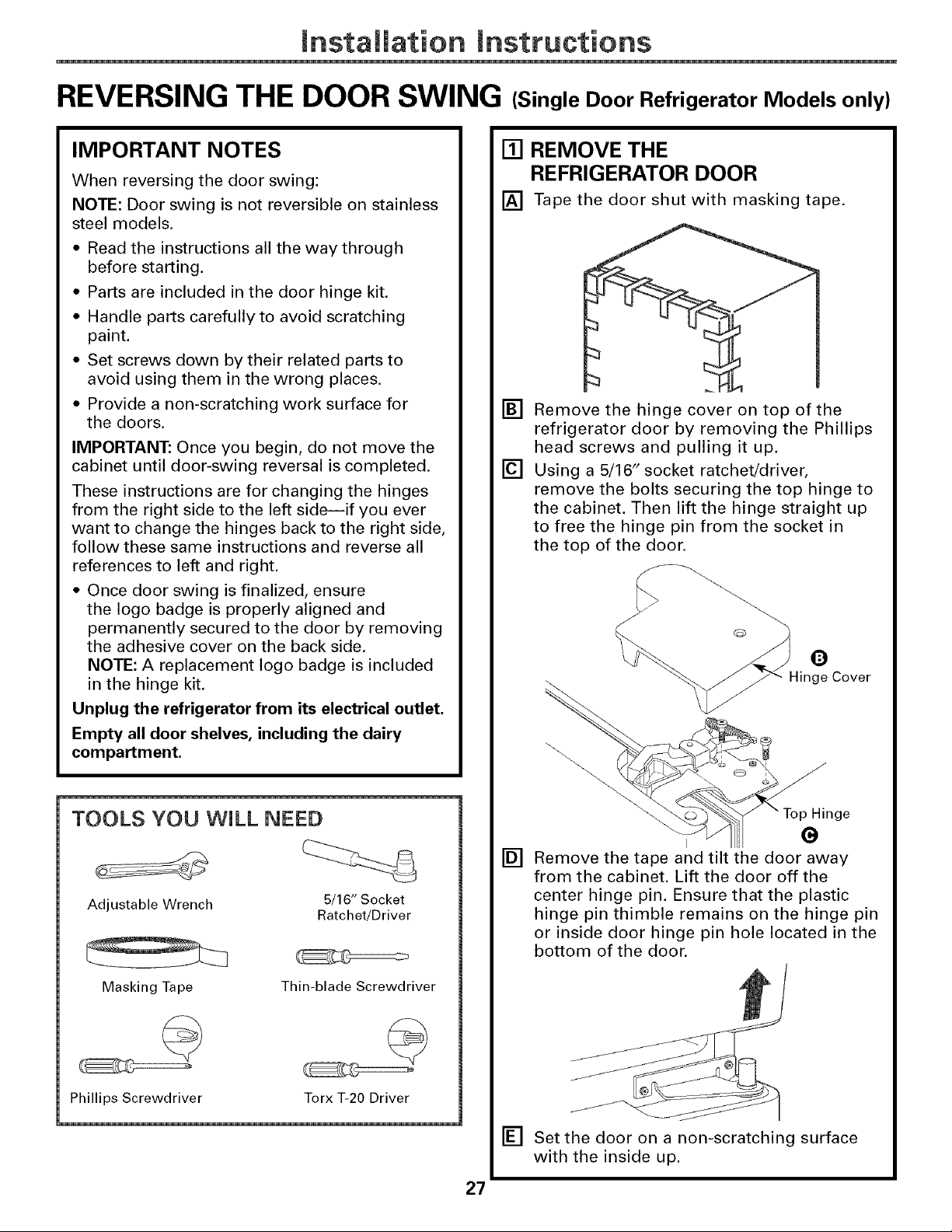
REVERSING THE DOOR SWING (Single Door Refrigerator Models only)
IMPORTANT NOTES
When reversing the door swing:
NOTE: Door swing is not reversible on stainless
steel models.
• Read the instructions all the way through
before starting.
• Parts are included in the door hinge kit.
• Handle parts carefully to avoid scratching
paint.
• Set screws down by their related parts to
avoid using them in the wrong places.
• Provide a non-scratching work surface for
the doors.
IMPORTANT: Once you begin, do not move the
cabinet until door-swing reversal is completed.
These instructions are for changing the hinges
from the right side to the left sideiif you ever
want to change the hinges back to the right side,
follow these same instructions and reverse all
references to left and right.
• Once door swing is finalized, ensure
the logo badge is properly aligned and
permanently secured to the door by removing
the adhesive cover on the back side,
NOTE: A replacement logo badge is included
in the hinge kit.
Unplug the refrigerator from its electrical outlet.
Empty all door shelves, including the dairy
compartment.
[] REMOVE THE
REFRIGERATOR DOOR
[] Tape the door shut with masking tape.
[] Remove the hinge cover on top of the
refrigerator door by removing the Phillips
head screws and pulling it up,
[] Using a 5/16" socket ratchet/driver,
remove the bolts securing the top hinge to
the cabinet. Then lift the hinge straight up
to free the hinge pin from the socket in
the top of the door.
O
-linge Cover
TOOLS YOU WiLL NEED
Adjustable Wrench 5/16" Socket
Masking Tape
Phillips Screwdriver
Ratchet!Driver
Thin-blade Screwdriver
Torx T-20 Driver
____nge
[]
Remove the tape and tilt the door away
from the cabinet. Lift the door off the
center hinge pin. Ensure that the plastic
hinge pin thimble remains on the hinge pin
or inside door hinge pin hole located in the
bottom of the door.
[] Set the door on a non-scratching surface
with the inside up.
27
mnstaliation mnstructions
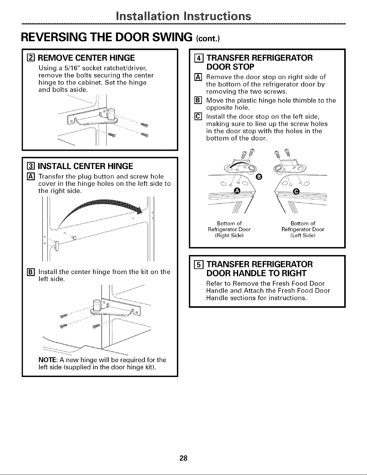
REVERSING THE DOOR SWING (cont.)
[] REMOVE CENTER HINGE
Using a 5/16" socket ratchet/driver,
remove the bolts securing the center
hinge to the cabinet. Set the hinge
and bolts aside.
[] INSTALL CENTER HINGE
[] Transfer the plug button and screw hole
cover in the hinge holes on the left side to
the right side.
TRANSFER REFRIGERATOR
[]
DOOR STOP
[]
Remove the door stop on right side of
the bottom of the refrigerator door by
removing the two screws.
[]
Move the plastic hinge hole thimble to the
opposite hole.
[]
Install the door stop on the left side,
making sure to line up the screw holes
in the door stop with the holes in the
bottom of the door.
Bottom of Bottom of
Refrigerator Door Refrigerator Door
(Right Side) (Left Side)
[] Install the center hinge from the kit on the
left side.
NOTE: A new hinge will be required for the
left side (supplied in the door hinge kit).
ITI TRANSFER REFRIGERATOR
DOOR HANDLE TO RIGHT
Refer to Remove the Fresh Food Door
Handle and Attach the Fresh Food Door
Handle sections for instructions.
28
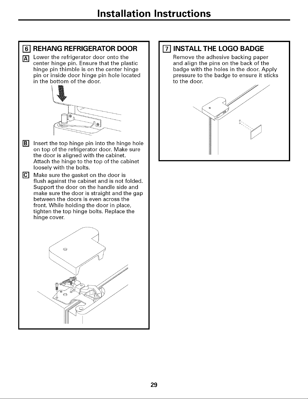
Installation Instructions
[] REHANG REFRIGERATOR DOOR
[] Lower the refrigerator door onto the
center hinge pin. Ensure that the plastic
hinge pin thimble is on the center hinge
pin or inside door hinge pin hole located
in the bottom of the door.
[]
Insert the top hinge pin into the hinge hole
on top of the refrigerator door. Make sure
the door is aligned with the cabinet.
Attach the hinge to the top of the cabinet
loosely with the bolts.
[]
Make sure the gasket on the door is
flush against the cabinet and is not folded.
Support the door on the handle side and
make sure the door is straight and the gap
between the doors is even across the
front. While holding the door in place,
tighten the top hinge bolts. Replace the
hinge cover.
[] INSTALL THE LOGO BADGE
Remove the adhesive backing paper
and align the pins on the back of the
badge with the holes in the door. Apply
pressure to the badge to ensure it sticks
to the door.
29
mnstaliation mnstructions
REMOVING THE DOORS (Double Door Refrigerator Models only)
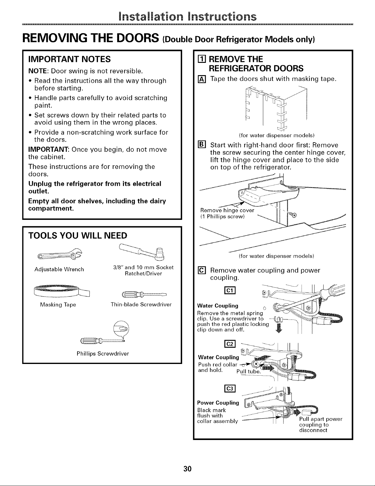
IMPORTANT NOTES
NOTE: Door swing is not reversible.
• Read the instructions all the way through
before starting.
• Handle parts carefully to avoid scratching
paint.
• Set screws down by their related parts to
avoid using them in the wrong places.
• Provide a non-scratching work surface for
the doors.
IMPORTANT: Once you begin, do not move
the cabinet.
These instructions are for removing the
doors.
Unplug the refrigerator from its electrical
outlet.
Empty all door shelves, including the dairy
compartment.
TOOLS YOU WILL NEED
[] REMOVE THE
REFRIGERATOR DOORS
[] Tape the doors shut with masking tape.
(for water dispenser models)
[] Start with right-hand door first: Remove
the screw securing the center hinge cover,
lift the hinge cover and place to the side
on top of the refrigerator.
Remo__
Adjustable Wrench 3/8" and 10 mm Socket
Masking Tape
Phillips Screwdriver
Ratchet/Driver
Thin-blade Screwdriver
(for water dispenser models)
[] Remove water coupling and power
coupling.
Water Coupling
Remove the metal spring _-_
clip. Use a screwdriver to --_}[_-_._
push the red plastic locking "_- ]
clip down and off. _,
Water Coupling
Pushredcollar g
and hold. Pull tub'e__
Power Coupling
Black mark
flush with
collar assembly
Pull apart power
coupling to
disconnect
30
 Loading...