

GE CDWT980R10SS, GDWF100R10BB, GDWF100R10WW, GDWF100R30BB, GDWF100R30WW Installation Guide
...
04 _,Mf
Appliances
Installation Instructions
Built-In Dishwasher
If you have questions, call 800.GE.CARES(800.432.2737) or visit our Website at: GEAppliances.com
In Canada call 1.800.561.3344 or www.GEAppliances.ca
BEFORE YOU BEGIN
Readthese instructions completely and
carefully.
IM PORTANT Observeallgoverning codesand
ordinances.
• Note to Installer - Besure to leave these instructions for the
consumer's and local inspector's use.
• Note to Consumer - Keep these instructions with your
Owner's Manual for future reference.
• Skill Level- Installation of this dishwasher requires
basic mechanical, electrical and plumbing skills. Proper
installation is the responsibility of the installer. Product
failure due to improper installation is not covered under
the GEAppliance Warranty. Seewarranty information.
• Completion Time - 1to 3 Hours. New installations require
more time than replacement installations.
READ CAREFULLY.
KEEP THESE INSTRUCTIONS.
Stainless SteelTub Models
| L J l"_t'_ _'T'A k |'It
I Ivli_Ui_ | _l_l| - The dishwasherMUST
be installedtoallowforfutureremovalfromtheenclosure
if service is required.
If you received a damaged dishwasher, you should
immediately contact your dealer or builder.
Optional Accessories - See the Owner's Manual for available
custom panel kits.
FOR YOUR SAFETY
Read and observe all CAUTIONSand WARNINGS
shown throughout these instructions, While performing
installations described in this booklet, gloves and either
safety glasses or goggles should be worn,
imagination at work
Installation Preparation
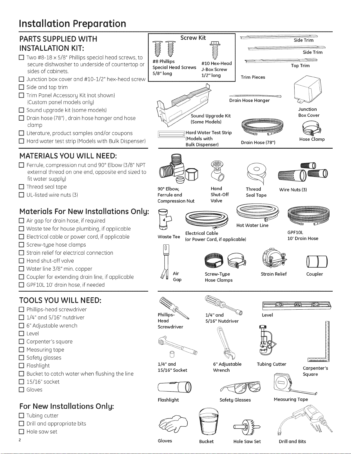
PARTS SUPPLIED WITH
INSTALLATION KIT:
[] Two #8-18 x 5/8" Phillips special head screws, to
secure dishwasher to underside of countertop or
sides of cabinets.
[] Junction box cover and #!0-1/2" hex-head screw
[] Side and top trim
[] Trim Panel Accessorg Kit (not shown)
(Custom panel models onlg)
[] Sound upgrade kit (some models)
[] Drain hose (78"), drain hose hanger and hose
clamp
[] Literature, product samples and/or coupons
[] Hard water test strip (Models with Bulk Dispenser)
MATERIALS YOU WILL NEED:
[] Ferrule, compression nut and 90° Elbow (5/8" NPT
external thread on one end, opposite end sized to
fit water supplg)
[] Thread seal tape
[] UL-listed wire nuts (3)
Screw Kit
??
#8 Phillips
Special Head Screws
5/8" long
_ound Upgrade Kit
{Some Models)
tl Hard Water Test Strip
J(Models with
Bulk Dispenser)
90° Elbow, Hand Thread Wire Nuts (3)
Ferrule and Shut-Off Seal Tape
Compression Nut Valve
?
#10 Hex-Head
J-Box Screw
1/2" long
Trim Pieces
Drain Hose Hanger
Drain Hose (78")
Side Trim
Side Trim
Top Trim
Q
Junction
Box Cover
Hose Clamp
Materials For New Installations Only:
[] Air gap for drain hose, if required
[] Waste tee for house plumbing, if applicable
[] Electrical cable or power cord, if applicable
[] Screw-tgpe hose clamps
[] Strain relief for electrical connection
[] Hand shut-off valve
[] Water line 5/8" min. copper
[] Coupler for extending drain line, if applicable
[] GPF10L !0' drain hose, if needed
TOOLS YOU WILL NEED:
[] Phillips-head screwdriver
[] !/4" and 5/16" nutdriver
[] 6" Adjustable wrench
[] Level
[] Carpenter's square
[] Measuring tape
[] Safetg glasses
[] Flashlight
[] Bucket to catch water when flushing the line
[] !5/16" socket
[] Gloves
Waste Tee
_ Air
Gap
Head
Screwdriver
114"and
15116" Socket
Hot Water Line
Electrical Cable
(or Power Cord, if applicable)
Screw-Tgpe Strain Relief Coupler
Hose Clumps
5/16" Nutdriver
6" Adjustable Tubing Cutter
Wrench Carpenter's
GPF20L
20' Drain Hose
Level
For New Installations Only:
[] Tubing cutter
[] Drill and appropriate bits
[] Holesaw set
2
Flashlight
Gloves
Safetg Glasses Measuring Tape
Bucket Hole Saw Set Drill and Bits
Installation Preparation-Enclosure
PREPARE DISHWASHER ENCLOSURE
To reducethe riskofshock,fire,orinjurg
topersons,the installermust ensurethat
thedishwasheriscompletelgenclosedat
thetimeof installation.
Pare reducir el riesgo de choque, incendio
o lesi6n a personas, el instalador se
debe cerciorar de que la lavadora est_
completamente cerrada en elmomento
de lainstalaci6n.
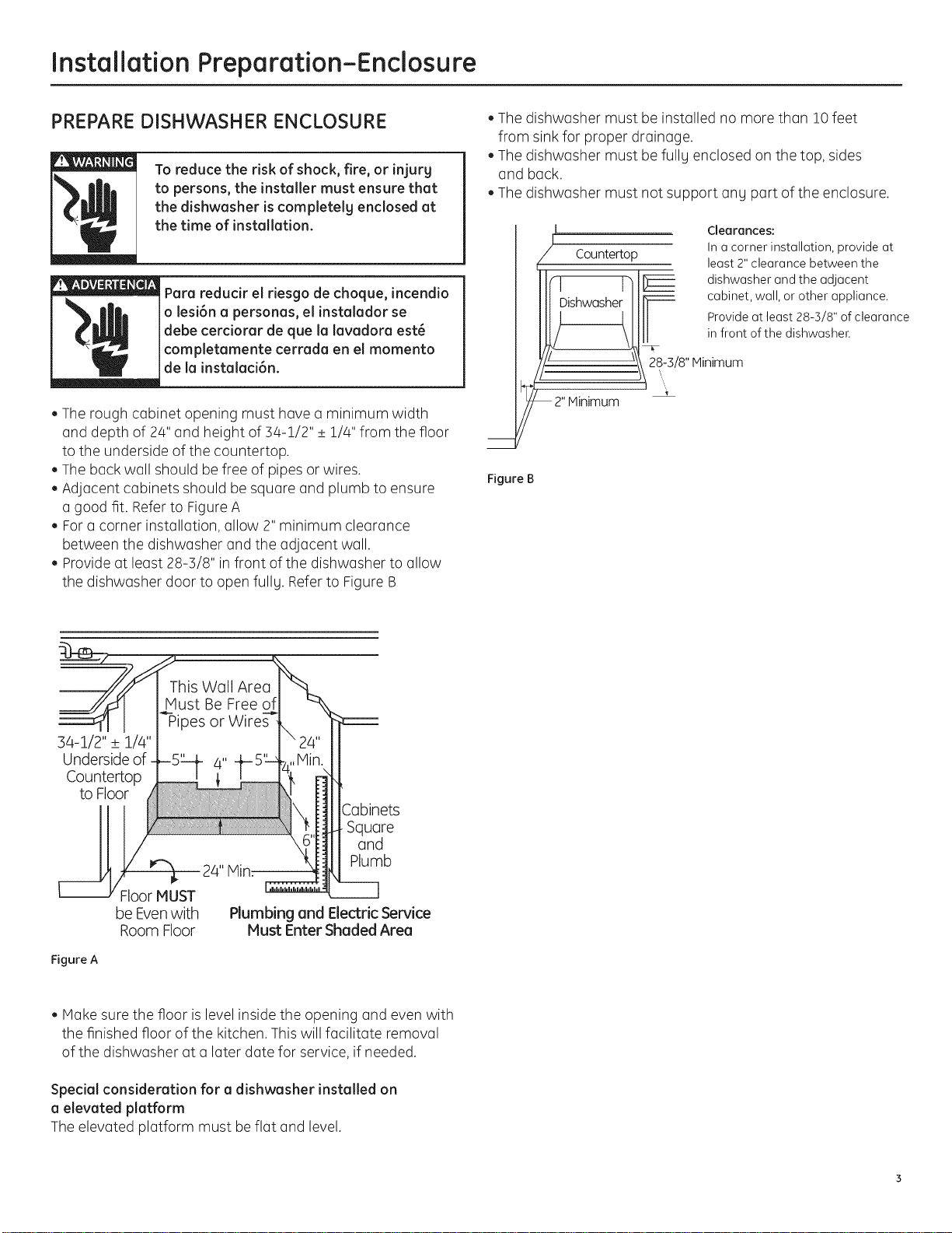
•The rough cabinet opening must have a minimum width
and depth of 24" and height of ]4-1/2" _+1/4" from the floor
to the underside of the countertop.
• The back wall should be free of pipes or wires.
Adjacent cabinets should be square and plumb to ensure
a good fit. Referto Figure A
For a corner installation, allow 2" minimum clearance
between the dishwasher and the adjacent wall.
Provide at least 28-5/8" in front of the dishwasher to allow
the dishwasher door to open fully. Referto Figure B
• The dishwasher must be installed no more than 10 feet
from sink for proper drainage.
The dishwasher must be fullg enclosed on the top, sides
and back.
The dishwasher must not support any part of the enclosure.
[
Countertop
Dishwasher
28-3/8" Minimum
2" Minimum
Figure B
Clearances:
In a corner installation, provide at
least 2" clearance between the
dishwasher and the adjacent
cabinet, wall, or other appliance.
Provide at least 28-3/8" of clearance
in front of the dishwasher.
34-1/2" + 1/4"
Underside of
Countertop
to Floor
Squore
ond
J 24" Min:
Plumb
Floor MUST
be Even with
Room Floor
Figure A
Plumbing and Electric Service
Must Enter Shaded Area
• Moke sure the floor is level inside the opening and even with
the finished floor of the kitchen. This will facilitate removal
of the dishwasher at a later date for service, if needed.
Special consideration for a dishwasher installed on
a elevated platform
The elevated platform must beflat and level.
InstallationPreparation-Drain
PREPARE DRAIN PLUMBING
Drain Requirements
• Drain hose must not exceed 10 feet in length.
• A high drain loop or air gap is required. See below.
Drain Method
The tgpe of drain installation depends on the following:
• Do local codes or ordinances require an air gap?
• Iswaste tee less than 18" above the floor?
If the answer to either question is yes, an air gap must be used.
Referto Method 1 (Figure C)in the adjacent illustrations.
If both answers are no, either an air gap or high drain loop mag
be used. Refer to Method 1 (Figure C)or Method 2 (Figure D)
in the adjacent illustrations
NOTE: Drain hose elevation must not exceed 48".
Special consideration for a dishwasher installed on
a elevated platform
Ifthe dishwasher isinstalled on an elevated platform, a high
drain loop of at least 32" above the platform must be provided
in addition to the air gap or drain loop requirement determined
above. This is necessmrgfor proper drain performance.
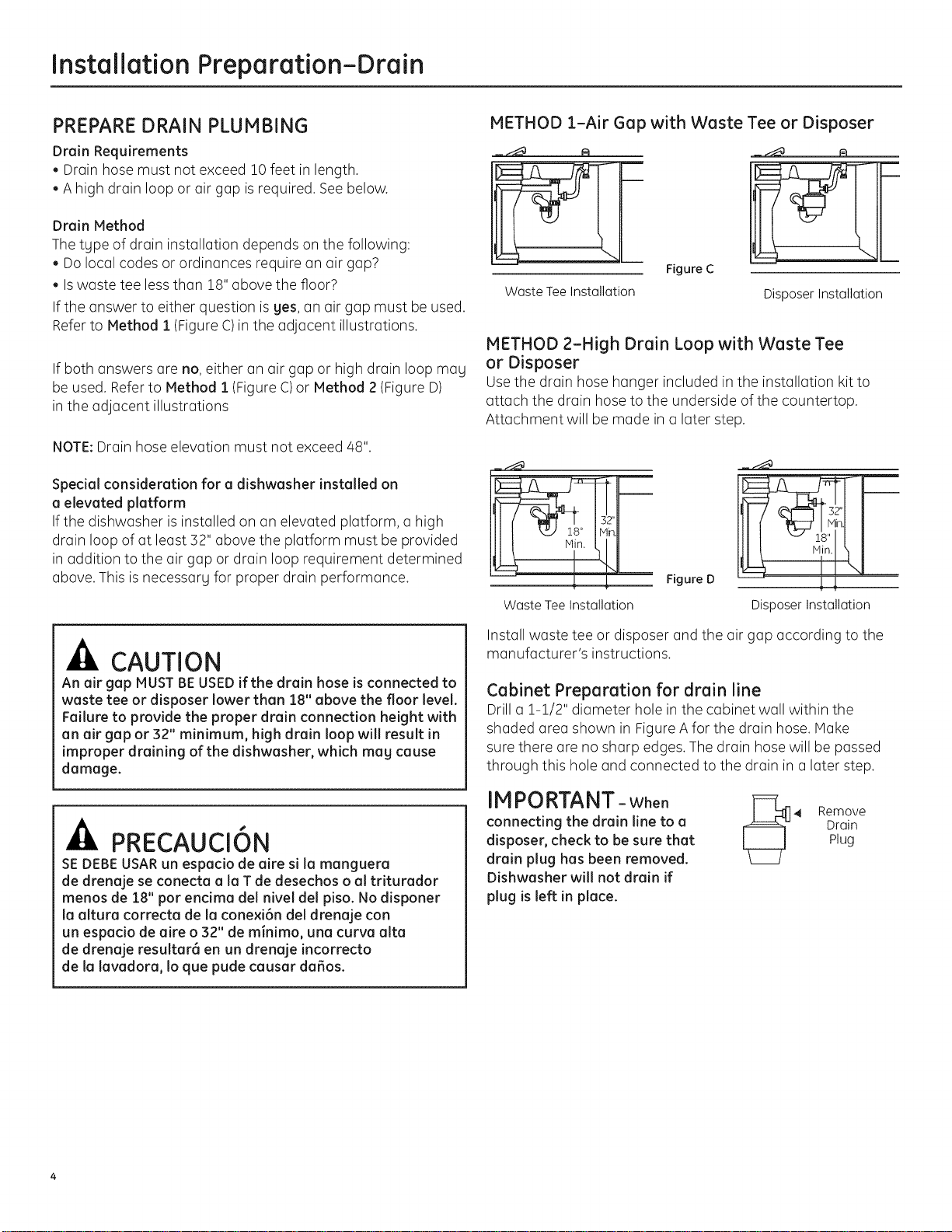
METHOD 1-Air Gap with Waste Tee or Disposer
Figure C
Waste TeeInstallation
Disposer Installation
METHOD 2-High Drain Loop with Waste Tee
or Disposer
Usethe drain hose hanger included in the installation kit to
attach the drain hose to the underside of the countertop.
Attachment will be made in a later step.
in.
_ Figure D
Waste Tee Installation
DisposerInstallation
CAUTION
An air gap MUSTBEUSEDif the drain hose is connected to
waste tee or disposer lower than 18" above the floor level.
Failure to provide the proper drain connection height with
an air gap or 32" minimum, high drain loop will result in
improper draining of the dishwasher, which may cause
damage.
PRECAUCION
SEDEBEUSARun espacio de aire si la manguera
de drenaje se conecta a la T de desechos o al triturador
menos de 18" por encima del nivel del piso. No disponer
la altura correcta de la cone×i6n del drenaje con
un espacio de aire o 32" de minimo, una curva alta
de drenaje resultar_ en un drenaje incorrecto
de la lavadora, Io que pude causar da6os.
Install waste tee or disposer and the air gap according to the
manufacturer's instructions.
Cabinet Preparation for drain line
Drill a 1-1/2" diameter hole in the cabinet wall within the
shaded area shown in Figure A for the drain hose. Make
sure there are no sharp edges. The drain hose will be passed
through this hole and connected to the drain in a later step.
IMPORTANT-when
connecting the drain line to a
disposer, check to be sure that
drain plug has been removed.
Dishwasher will not drain if
plug is left in place.
Drain
Plug
_ Remove
Installation Preparation-Electrical Supplg
PREPARE ELECTRICAL WIRING
FOR PERSONAL SAFETY: Remove house fuse
or open circuit breaker before beginning
installation. Do not use an extension cord or
adapter plug with this appliance.
I I
/ I
/ I
Alternate q',
Receptacle , \
I \
Location
1-1/2" Dia.
Hole (Max.)
PARASEGURIDAD PERSONAL: Retire el
fusible de la casa o abra el interruptor de
circuitos antes de empezar la instalaci6n.
No use un cable de extensi6n o enchufe
adaptador con este aparato.
Electrical Requirements
• This appliance must besupplied with 120V,60Hz., and
connected to an individual properlg grounded branch circuit
protected bg a 15- or 20-ampere circuit breaker or time-
delag fuse.
• Wiring must be 2 wire with ground and rated for 75°C(176°F).
• If the electrical supplg does not meet the above
requirements, call a licensed electrician before proceeding.
Grounding Instructions-Permanent Connection
This appliance must be connected to a grounded-metal,
permanent wiring sgstem, or an equipment-grounding
conductor must be run with the circuit conductors and be
connected to the equipment-grounding terminal or lead on
the appliance.
Grounding Instructions-Power Cord Hodels
This appliance must be grounded. Inthe event of a malfunction
or breakdown, grounding will reduce the risk of electric shock
by providing a path of least resistance for electric current.
This appliance is equipped with a cord having an equipment-
grounding conductor and a grounding plug. The plug must
be plugged into an appropriate outlet that is installed and
grounded inaccordance with all local codes and ordinances.
_The improper connection of the equipment
grounding conductor can result in a risk
of electric shock. Check with a qualified
electrician or service representative if gou
are in doubt that the appliance is properlg
grounded.
3" from
Cabinet
Location
Area
Figure E White
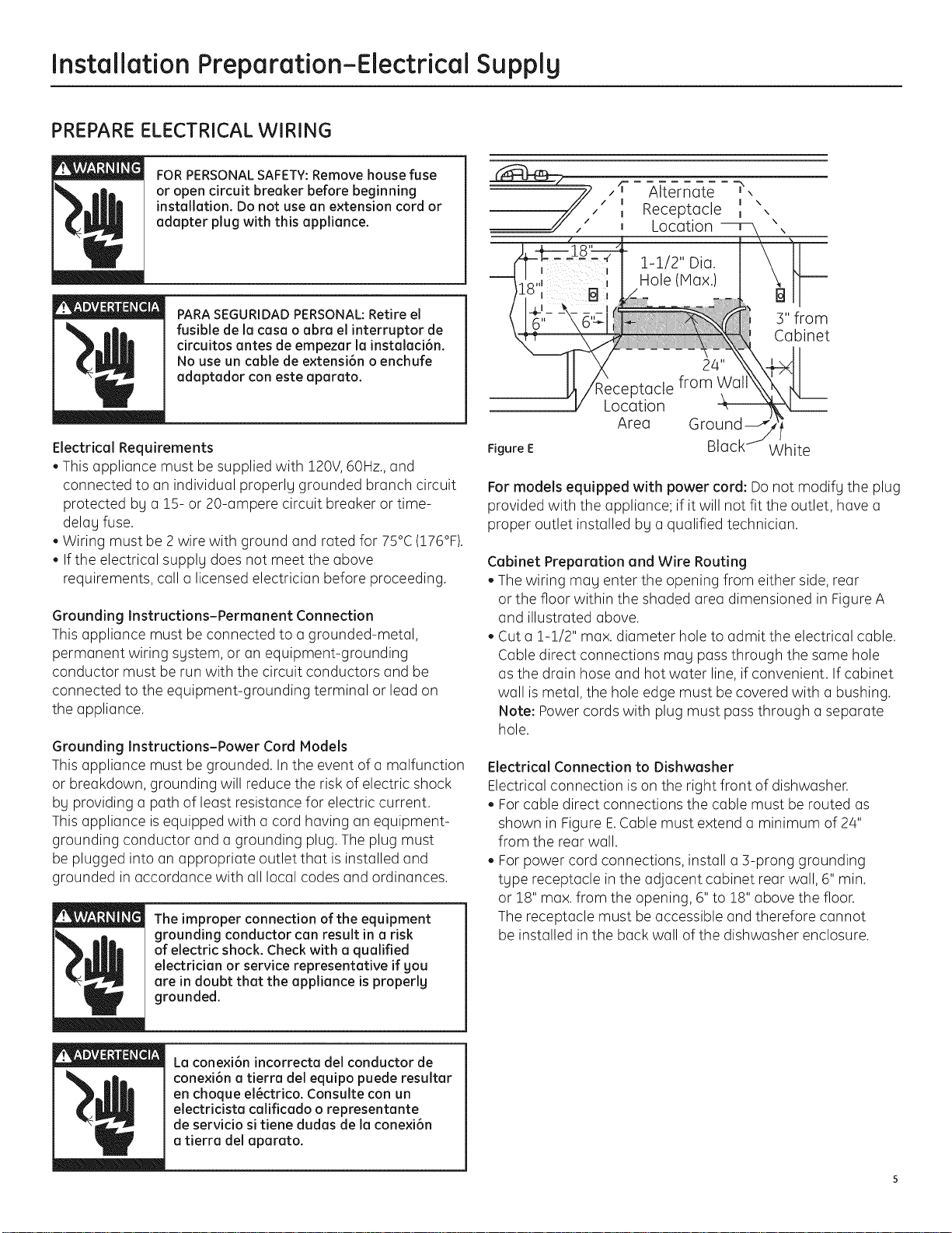
For models equipped with power cord: Do not modifg the plug
provided with the appliance; if it will not fit the outlet, have a
proper outlet installed by a qualified technician.
Cabinet Preparation and Wire Routing
• The wiring mag enter the opening from either side, rear
or the floor within the shaded area dimensioned in Figure A
and illustrated above.
Cut a !-!/2" max. diameter holeto admit the electrical cable.
Cable direct connections mag pass through the same hole
as the drain hose and hot water line, if convenient. If cabinet
wall is metal, the hole edge must be covered with a bushing.
Note: Power cords with plug must pass through a separate
hole.
Electrical Connection to Dishwasher
Electrical connection is on the right front of dishwasher.
Forcable direct connections the cable must be routed as
shown in Figure E.Cable must extend a minimum of 24"
from the rear wall.
Forpower cord connections, install a ]-prong grounding
tgpe receptacle inthe adjacent cabinet rear wall, 6" min.
or 18" max. from the opening, 6" to 18" above the floor.
The receptacle must be accessible and therefore cannot
be installed in the back wall of the dishwasher enclosure.
La conexi6n incorrecta del conductor de
conexi6n a tierra del equipo puede resultar
en choque el6ctrico. Consulte con un
electricista calificado o representante
de servicio si tiene dudas de la conexi6n
a tierra del aparato.
5
Installation Preparation-Hot Water Supply
PREPARE HOT WATER SUPPLY
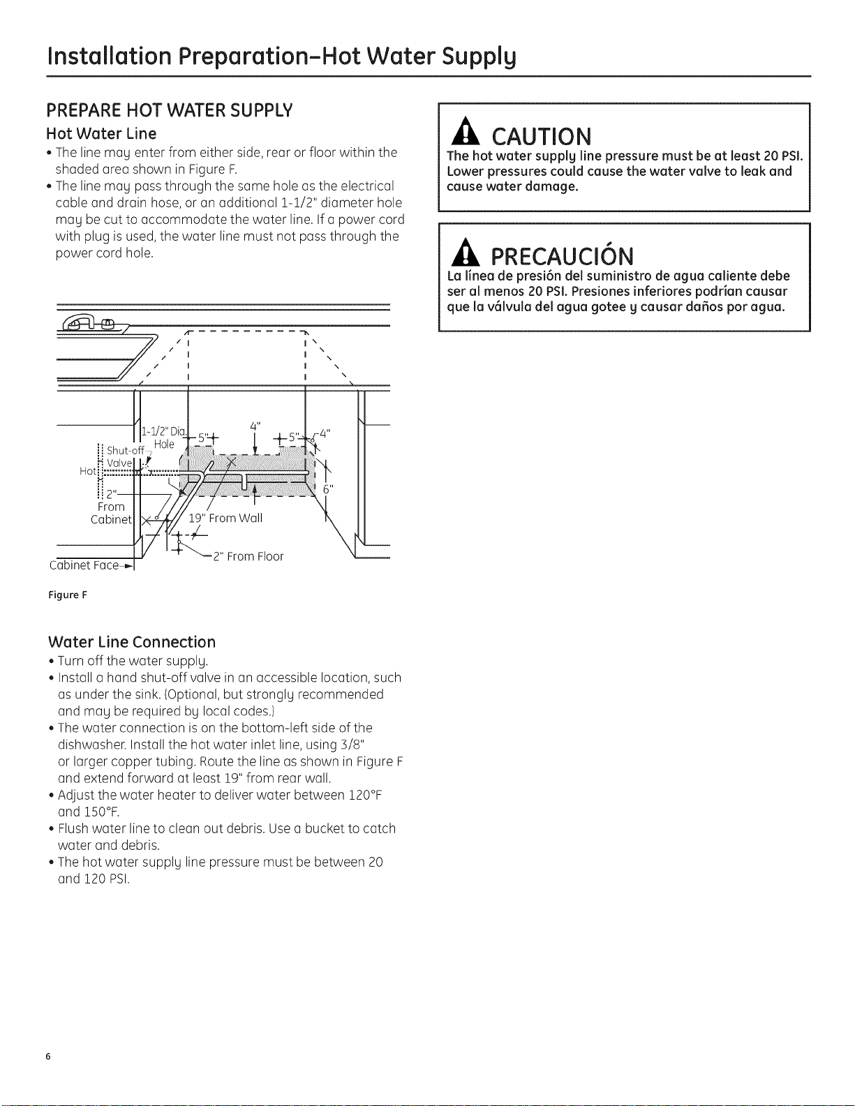
Hot Water Line
• The line meg enter from either side, rear or floor within the
shaded area shown in Figure F.
• The line meg pass through the same hole as the electrical
cable and drain hose, or an additional 1-!/2" diameter hole
meg be cut to accommodate the water line. Ifa power cord
with plug is used, the water line must not pass through the
power cord hole.
=_
I \
\
I \
I \
I \
/ I
_1-1/2" Oi,
ii Shut-off7
Valve Y
Hot_ i:::::::::: ,%.:',::',:':
P.
:: L.
_2"
From
Cabinet
Hole
I__.!9" From Wall
/
I
I
The hot water supplg line pressure must be at least 20 PSI.
Lower pressures could cause the water valve to leak and
cause water damage.
La linea de presi6n del suministro de ague caliente debe
ser al menos 20 PSI.Presiones inferiores podrian causer
que la v61vula del ague gotee g causer da_os por ague.
CAUTION
PRECAUCI6N
2" From Floor
CabinetFace_,-
Figure F
Water Line Connection
• Turn offthe water supplg.
• Install a hand shut-off valve in an accessible location, such
as under the sink. (Optional, but stronglg recommended
and meg be required bg local codes.)
• The water connection is on the bottom-left side of the
dishwasher. Install the hot water inlet line, using 3/8"
or larger copper tubing. Routethe line as shown in Figure F
and extend forward at least 19" from rear wall.
• Adjust the water heater to deliver water between 120°F
and !50°F.
• Flush water line to clean out debris. Use a bucket to catch
water and debris.
• The hot water supplg line pressure must be between 20
and 120 PSI.
Dishwasher Installation
CAUTION
Do not remove the wood base until you are ready to
install the dishwasher. The dishwasher will tip over
when the door isopened if the base is removed.
PRECAUCION
No retire la base de madera hasta que est_ listo para
instalar la lavadora de platos. Cuando la puerta se abra,
la lavadora de platos se inclinar6 si la base se retira.
STEP 1 - LOCATE INSTALLATION ITEMS
• Locate the items in the installation package and set aside for
use in the listed steps.
• Trim pieces - Step 2
Junction box cover - Step 7 or Step 18
Drain hose and clamp - Step 10
Screw Kit - Step 15
Drain hose hanger - Step 17
Owner's Manual - Step 19 and Step 24
Hard Water test strip - Step 21
Sound upgrade kit (selected models) - Step 22
Product samples and/or coupons - Step 24
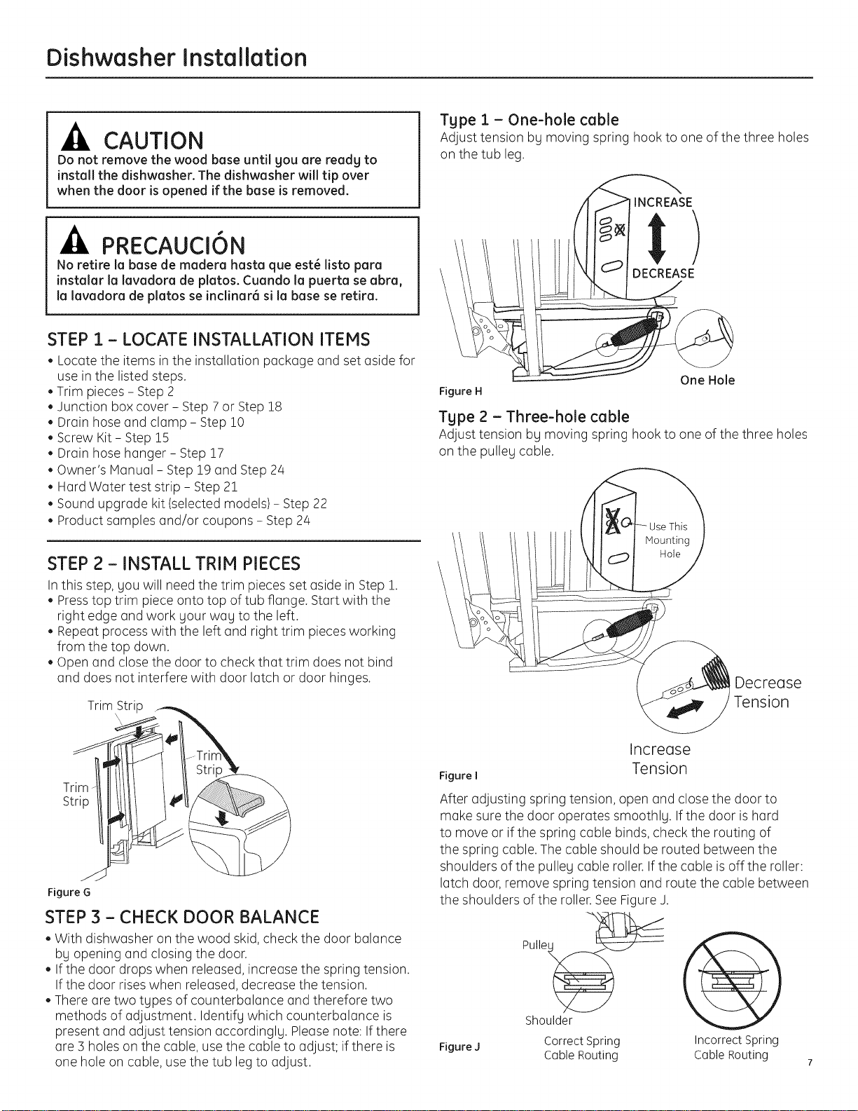
Tgpe 1 - One-hole cable
Adjust tension bg moving spring hook to one of the three holes
on the tub leg.
!INCREASE
DECREASE
One Hole
Figure H
Tgpe 2 - Three-hole cable
Adjust tension bg moving spring hook to one of the three holes
on the pulley cable.
STEP 2 - INSTALL TRIM PIECES
Inthis step, gou will need the trim pieces set aside in Step 1.
Presstop trim piece onto top of tub flange. Start with the
right edge and work gour wag to the left.
Repeat process with the left and right trim pieces working
from the top down.
Open and close the door to check that trim does not bind
and does not interfere with door latch or door hinges.
TrimStrip
Trim -
Strip
Figure G
STEP 3 - CHECK DOOR BALANCE
• With dishwasher on the wood skid, check the door balance
bg opening and closing the door.
If the door drops when released, increase the spring tension.
If the door rises when released, decrease the tension.
There are two tgpes of counterbalance and therefore two
methods of adjustment. Identifg which counterbalance is
present and adjust tension accordinglg. Please note: Ifthere
are 3 holes on the cable, use the cable to adjust; if there is
one hole on cable, use the tub legto adjust.
Decrease
Increase
Figure I
After adjusting spring tension, open and close the door to
make sure the door operates smoothlg. If the door is hard
to move or if the spring cable binds, check the routing of
the spring cable. The cable should be routed between the
shoulders of the pulleg cable roller. If the cable isoff the roller:
latch door, remove spring tension and route the cable between
the shoulders of the roller.See Figure J.
Pulle__
Shoulder
Figure J
Correct Spring
Cable Routing
Tension
IncorrectSpring
CableRouting 7
Dishwasher Installation
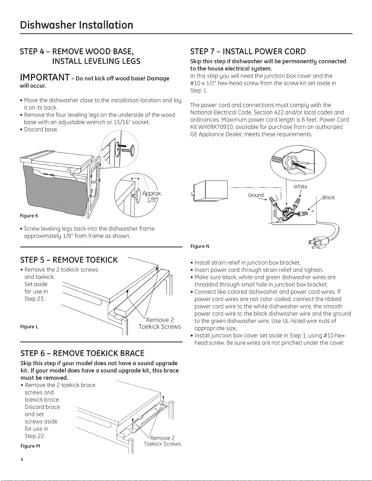
STEP 4 - REMOVE WOOD BASE,
INSTALL LEVELING LEGS
IMPORTANT- Donotkickoffwoodbase!Damage
will occur.
. Move the dishwasher close to the installation location and lag
it on its back.
• Remove the four leveling legs on the underside of the wood
base with an adjustable wrench or 15/!6" socket.
• Discard base.
)rox.
Figure K
STEP 7 - INSTALL POWER CORD
Skip this step if dishwasher will be permanentlg connected
to the house electrical sgstem.
In this step gou will need the junction box cover and the
#!0 x !/2" hex-head screw from the screw kit set aside in
Step i.
The power cord and connections must complg with the
National Electrical Code,Section/422 and/or local codes and
ordinances. Maximum power cord length is 6 feet. Power Cord
Kit wxogx70910, available for purchase from an authorized
GEAppliance Dealer,meets these requirements.
Ground
. Screw leveling legs back into the dishwasher frame
approximatelg !/8" from frame as shown.
STEP 5 - REMOVE TOEKICK
• Removethe 2toekick screws
and toekick.
Set aside
for use in
Step 23.
_,emove 2
Figure L Toekick Screws
STEP 6 - REMOVE TOEKICK BRACE
Skip this step if your model does not have a sound upgrade
kit. If your model does have a sound upgrade kit, this brace
must be removed.
• Remove the 2 toekick brace
screws and
toekick brace.
Discard brace
and set
screws aside
for use in
Step 22.
Figure M
;emove 2
Toekick Screws
Figure N
• Install strain relief injunction box bracket.
• Insert power cord through strain relief and tighten.
Make sure black, white and green dishwasher wires are
threaded through small hole injunction box bracket.
Connect like-colored dishwasher and power cord wires. If
power cord wires are not color-coded, connect the ribbed
power cord wire to the white dishwasher wire, the smooth
power cord wire to the black dishwasher wire and the ground
to the green dishwasher wire. Use UL-listed wire nuts of
appropriate size.
Install junction box cover set aside in Step 1, using #!0 hex-
head screw. Besure wires are not pinched under the cover.
Dishwasher Installation
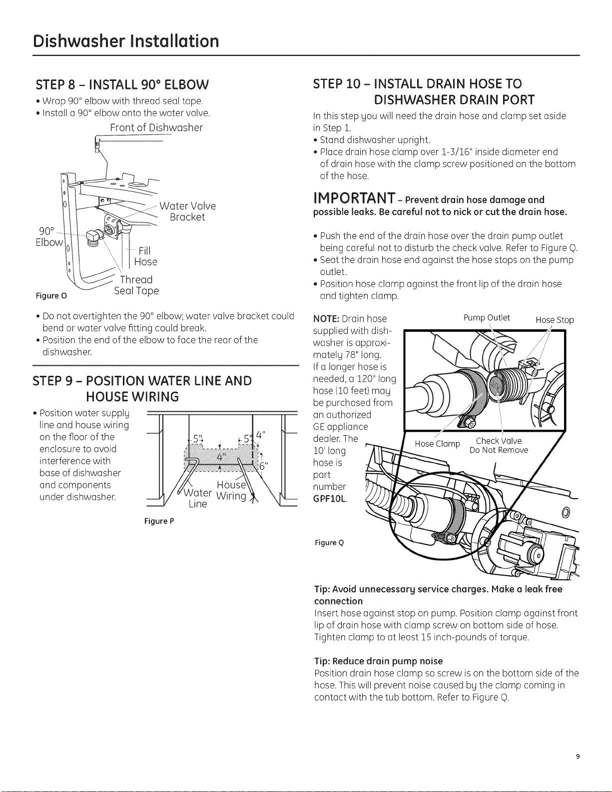
STEP 8 - INSTALL 90 ° ELBOW
• Wrap 90° elbow with thread seal tape.
• Install a 90° elbow onto the water valve.
Front of Dishwasher
Water Valve
90°
Elbow
I Hose
Thread
Figure 0
• Do not overtighten the 90° elbow; water valve bracket could
bend or water valve fitting could break.
Position the end of the elbow to face the rear of the
dishwasher.
Seal Tape
Bracket
STEP 9 - POSITION WATER LINE AND
HOUSE WIRING
• Position water supply
line and house wiring
on the floor of the
enclosure to avoid
interference with
base of dishwasher
and components
under dishwasher.
STEP I0 - INSTALL DRAIN HOSE TO
DISHWASHER DRAIN PORT
In this step you will need the drain hose and clamp set aside
in Step 1.
Stand dishwasher upright.
• Place drain hose clamp over 1-5/16" inside diameter end
of drain hose with the clamp screw positioned on the bottom
of the hose.
IMPORTANT- Prevent drain hose damage and
possible leaks. Be careful not to nick or cut the drain hose.
Push the end of the drain hose over the drain pump outlet
being careful not to disturb the check valve. Refer to Figure q).
Seat the drain hose end against the hose stops on the pump
outlet.
Position hose clamp against the front lip of the drain hose
and tighten clamp.
NOTE:Drain hose
supplied with dish-
washer isapproxi-
mately 78" long.
Ifa longer hose is
needed, a 120" long
hose (!0 feet) may
be purchased from
an authorized
GEappliance
dealer.The
!0' long
hose is
port
number
GPFIOL.
PumpOutlet HoseStop
\
Figure P
Figure Q
Tip: Avoid unnecessarg service charges. Makea leak free
connection
Insert hose against stop on pump. Position clamp against front
lip of drain hose with clamp screw on bottom side of hose.
Tighten clamp to at least !5 inch-pounds of torque.
Tip: Reduce drain pump noise
Position drain hose clamp so screw is on the bottom side of the
hose. This will prevent noise caused by the clamp coming in
contact with the tub bottom. Refer to Figure q).
Dishwasher Installation
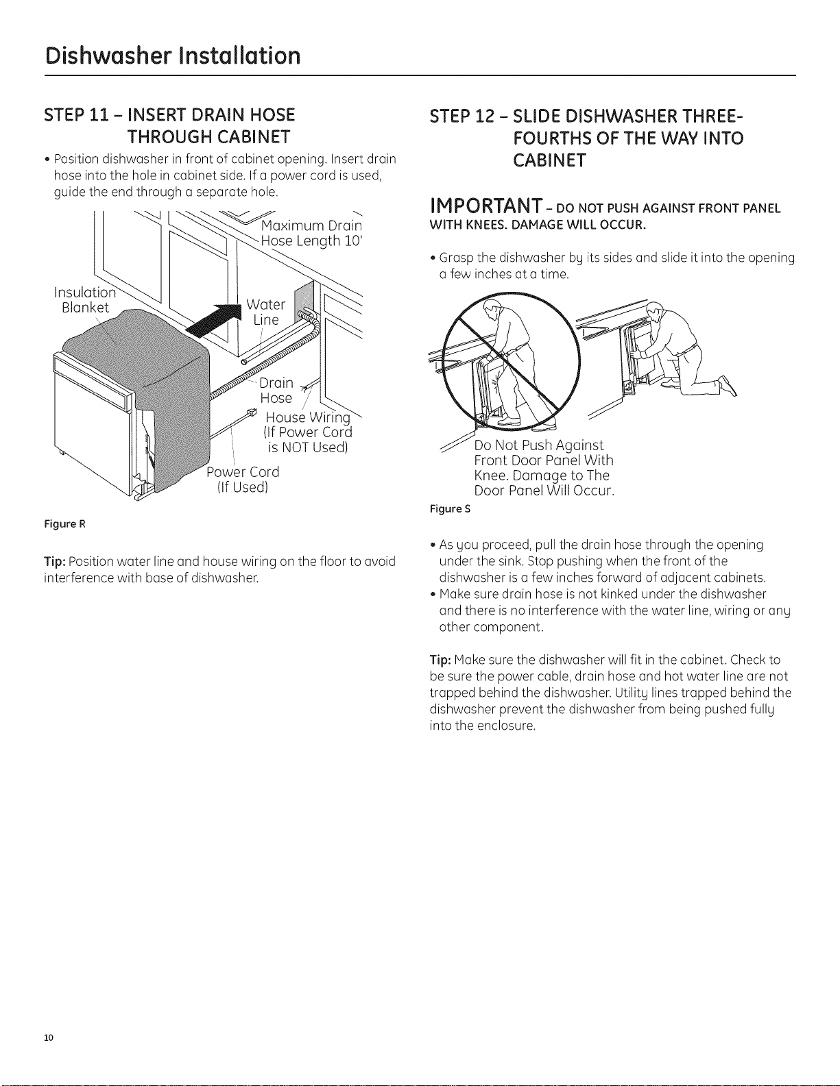
STEP 11 - INSERT DRAIN HOSE
THROUGH CABINET
• Position dishwasher in front of cabinet opening. Insert drain
hose into the hole in cabinet side. If a power cord is used,
guide the end through a separate hole.
Drain
Hose Length 10'
Blanket
Hose
/
House Wiring
(If Power Cord
is NOT Used)
Power Cord
(If Used)
Figure R
Tip: Position water line and house wiring on the floor to avoid
interference with base of dishwasher.
STEP 12 - SLIDE DISHWASHER THREE-
FOURTHS OF THE WAY INTO
CABINET
IM _UK i_l_l|- DO NOT PUSH AGAINST FRONT PANEL
WITH KNEES.DAMAGE WILL OCCUR.
',Grasp the dishwasher bg its sides and slide it into the opening
a few inches at a time.
o Not Push Against
Front Door Panel With
Knee. Damage to The
Door Panel Will Occur.
Figure S
• As gou proceed, pull the drain hose through the opening
under the sink. Stop pushing when the front of the
dishwasher isa few inches forward of adjacent cabinets.
• Make sure drain hose is not kinked under the dishwasher
and there is no interference with the water line,wiring or ang
other component.
Tip: Make sure the dishwasher will fit in the cabinet. Check to
be sure the power cable, drain hose and hot water line are not
trapped behind the dishwasher. Utilitg lines trapped behind the
dishwasher prevent the dishwasher from being pushed fullg
into the enclosure.
lO
 Loading...