

GE PDW7900P - Profile: Full Console Dishwasher, PDW7980PSS - 6 LEVEL 12 TOUCHPADS CONTOCONTOUR DOOR 5, GSD6000 Series, PDW7000 Series Installation Instructions Manual
/_ ¢,* i¢_¸ _._
Appliances
i< i i,3Lft_LlIL,
nstallation
instructions
Built-In Dishwasher
If you have questions, call 800.GE.CARES 1800.432.2737} or visit our website at: www.ge.com
BEFORE YOU BEGIN
Read these instructions completely and
carefully.
IMPORTANT.ThedishwasherMUST be installed
to oliow for future removal from the enclosure if service is
required.
,,,A,,_iPORTANT - Observeallgoverningcodesand
ordinances.
• Note to Installer - Be sure to leave these instructions for the
consumer's and local inspector's use,
• Note to Consumer - Keep these instructions with gour
Owner's Manuo! for future reference.
• Skill Level - Installation of this dishwasher requires
basic mechanical, electrical and plumbing skills. Proper
installation is the responsibility of the installer. Product
failui;e due to improper installation is not covered under
the GE Appliance warrontg, See warrantg information.
• Completion Time - 2 to 3 Hours, New installations require
more time than replacement installations.
If gOu received o damaged dishwasher, gou should
immediately contact gout dealer or builder.
Optional Accessories- Seethe 0wner!s Manual for available
custom panel kits,
FOR YOUR SAFETY
Read and observe all CAUTIONS and WARNINGS shown
throughout these instructions, While performing
installations described in this booklet, gloves, safetg glasses
or goggles should be worn.
READ CAREFULLY.
KEEP THESE INSTRUCTIONS.
GSD6000 Series
PDW7000 Series
imagination at work
Installation Preparation
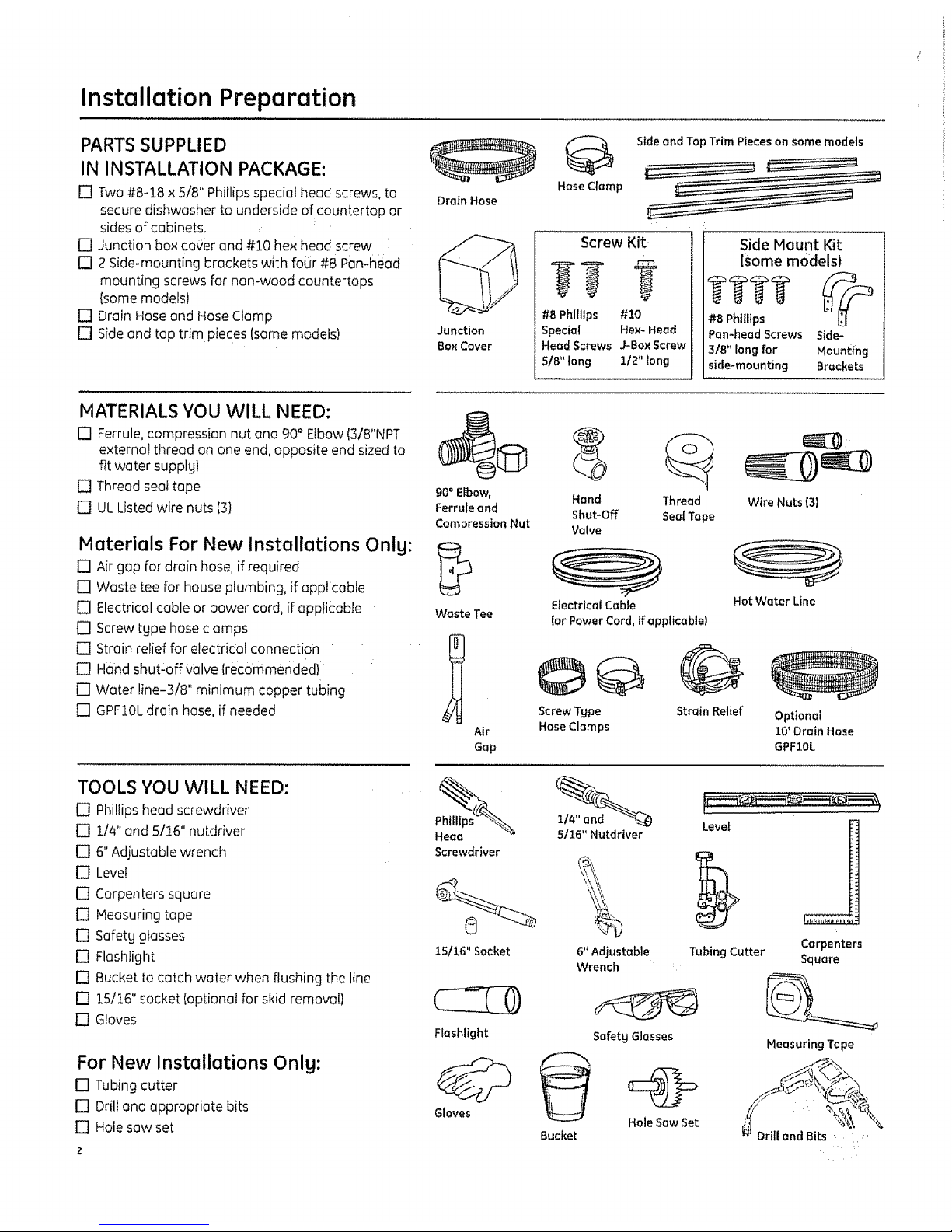
PARTS SUPPLIED
IN INSTALLATION PACKAGE:
[] Two #8-18 × 5/8" Phillips special head screws, to
secure dishwasher to underside of countertop or
sides of cabinets,
[] Junction box cover and #10 he× head screw
[] 2 Side-mounting brackets with four #8 Pan-head
mounting screws for non-wood countertops
{some models)
[] Drain Hose and Hose Clamp
[] Side and top trim pieces (some models)
DrainHose
Junction
Box Cover
Side and Top Trim Pieces on some models
Hose Clamp
Screw Kit
#8 Phillips #10
Special Hex-Head
HeadScrews J-Bo_Screw
SIB"long 1/2" long
SideMount Kit
(some models)
#8 Phillips
Pan-head Screws
3/8" long for
side-mounting
Side- :
Mounting
Brackets
MATERIALS YOU WILL NEED:
[] Ferrule, compression nut and 90° Elbow (3/8"NPT
externet thread on one end, opposite end sized to
fit water supply)
[] Thread seal tape
[] UL Listed wire nuts (3)
Materials For New Installations Only:
[] Air gap for drain hose, if required
[] Waste tee for house plumbing, if applicable
[] Electrical cable or power cord, if appficable
[] Screw tgpe hose clamps
[] Strain relief for electrical Connection
[] Hand shut:off V01ve{recommended}
D Water line-3!8" minimum copper tubing
[] GPF10L drain hose, if needed
TOOLS YOU WILL NEED:
[] Phillips head screwdriver
[] 114" and 5/16" nutdriver
[] 6" Adjustable wrench
[] Level
[] Carpenters square
[] Heasuring tope
[] Safetg gtasses
[] Flashlight
[] Bucket to catch water when flushing the line
[] 15/16" socket (optional for skid removal}
[] Gloves
For New Installations Only:
[] Tubing cutter
[] Drill and appropriate bits
[] Hole sow set
90° Elbow,
Ferrule and
Compression Nut
Waste Tee
Air
Gap
Screwdriver
°,3
"_r--
15116"Socket
Flashlight
Gloves
Hand Thread Wire Nuts 13)
Shut-Off SealTape
Valve
Electrical Cable
!or Power Cord, if applicable)
Hot Water Line
©@
ScrewType
HoseClamps
@
Strain Relief
Optional
10'Drain Hose
GPFZ0L
5116"Nutdriver
i)
6"Adjustable
Wrench
Safety Glasses
Bucket
Hole Saw Set
Level
Tubing Cutter
!
j
Carpenters
Square
MeasuringTape
n Drill and Bits
Installation Preparation
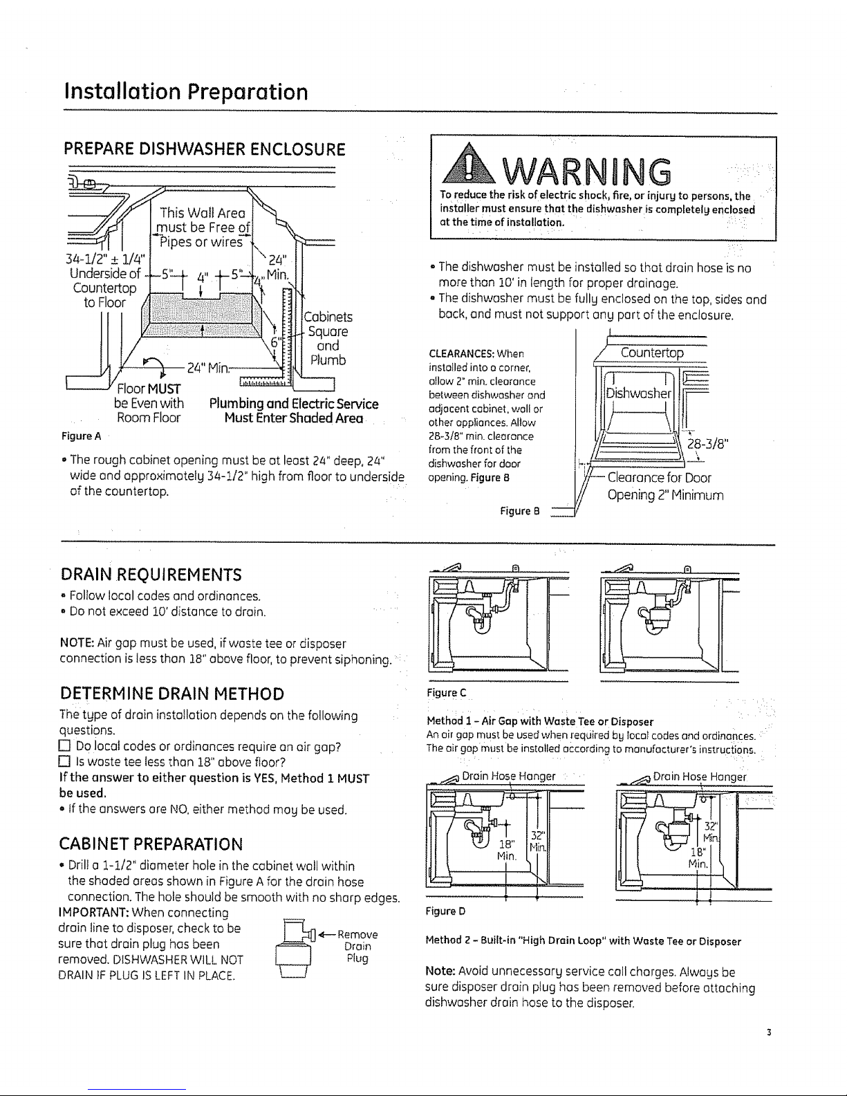
PREPARE DISHWASHER ENCLOSURE
34-1/2"_+ 1//4"
Underside of
Countertop
to Floor
Floor MUST
Figure A
This Wall Area
must be Free
_Pipes or wires
2abinets
Square
and
Plumb
24" Hin:
--q
be Evenwith Plumbing and Electric Service
Room Floor Must Enter Shaded Area
• The rough cabinet opening must be at least 24" deep, 2_"
wide and approximotelg 34-1/2" high from floor to underside
of the countertop.
WARNING
Toreduce the risk ofelectric shock, fire, or injurg to persons,the
installer must ensure that the dishwasher is completely enclosed
at the time of installation, ....
(V::
- The dishwasher must be installed so that drain hose is no
more than 10' in length for proper drainage.
• The dishwasher must be fullg enclosed on the top, sides and
back, and must not support and part of the enclosure.
I
Countertop
Dishwasher F
t.........!
28-3/8"
\
n Clearance for Door
opening 2" Hinimum
CLEARANCES:When
installed into a corner,
atlow 2" min. clearance
between dishwasher and
adjacent cabinet, wall or
other appliances. Allow
28_3/8" min. clearance
from the fron; of tile
dishwasher for door
opening. Figure B
Figure B
DRAIN REQUIREMENTS
a Follow local codes and ordinances.
Do not exceed 10' distance to drain.
NOTE: Air gap must be used, if waste tee or disposer
connection is less than 18" above floor, to prevent siphoning. ....
DETERMINE DRAIN METHOD
The type of drain installation depends on the following
questions.
[] Do local codes or ordinances require an air gap?
[] Is waste tee tess than 18" above floor?
If the answer to either question isYES, Method 1 MUST
be used.
o If the answers are NO. either method mad be used.
CABINET PREPARATION
• Drill a t-112" diameter hole in the cabinet wail within
the shaded areas shown in Figure A for the drain hose
connection. The hole should be smooth with no sharp edges.
IMPORTANT: When connecting
drain line to disposer, check to be ]==_
4--- Remove
sure that drain plug has been L__.Z--U_ Drain
removed. DISHWASHER WILL NOT _ Plug
DRAIN 1FPLUG IS LEFTIN PLACE.
L__J
FigureC .... :
MethodI - Air Gapwith Waste Teeor Disposer
Anair gap must beusedwhen {eqciiredbg Ioco_codesand ordin0nces.:
Theair gap must be installed accordingto manufacturer's instructions.
_ _ Drain Has? Hanger
I 2 i ,
3Z'
Hir_
Figure D
_ _ Drain HoseHanger
Method Z- Built-in "High Drain Loop" with Waste Tee or Disposer
Note: Avoidunnecessary service call charges.Alwags be
sure disposer drain plug has been removed before attaching
dishwasher drain hoseto the disposer,
Installation Preparation
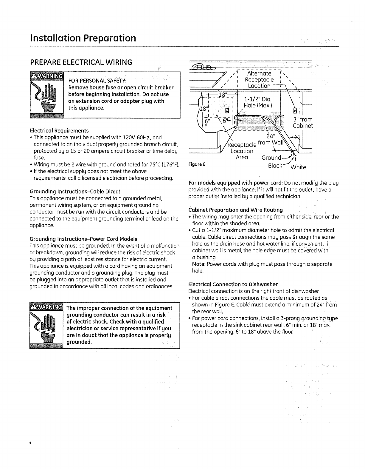
PREPARE ELECTRICAL WIRING
FORPERSONALSAFETVI " ' Receptacle : ",
_Ji Remove house fuse or open circuit breaker ' Location --r-k ",,
before beginning installation. Donot use
an extension cord or adapter plug with
this appliance, 8''ill ::
I ,:i
!
Electrical Requirements
• This appliance must be supplied with 120V, 60Hz.. and
connected to on individual properlg grounded branch circuit.
protected bg a 15 or 20 ampere circuit breaker or time delay
fuse.
oWiring must be 2 wire with ground and rated for 75°C {176%}.
• If the electrical supply does not meet the above
requirements, call a licensed electrician before proceeding.
8. /
:::::\ ; ! Hole(Max,} \ t]---
_,-F_ 3'from
! _: :':::: Ca,b',inet
/Receptacle from Wakkx_x_k
V Location
Area Ground-_' i
Figure E Black-" VVhite
Grounding Instructions-Cable Direct
This appliance must be connected to a grounded metal,
permanent wiring sgstem, or an equipment grounding
conductor must be run with the circuit conductors and be
connected to the equipment grounding terminal or lead on the
appliance.
Grounding Instructions-Power Cord Models
This appliance must be grounded. In tile event of o malfunction
or breakdown, grounding will reduce the risk of electric shock
bg providing a path of least resistance for electric current.
This appliance is equipped with o cord having an equipment
grounding conductor and a grounding plug. The plug must
be plugged into an appropriate outlet that is installed and
grounded in accordance with at! local codes end ordinances.
The improper connection of the equipment
grounding conductor can result in a risk
of electric shock. Check with a qualified
electrician or service representative if gou
are in doubt that the appliance is propertg
grounded.
For models equipped with power cord: Do not modifg the plug
provided with the appliance; if it will not fit the outlet hove a
proper outlet installed by a qualified technician.
Cabinet Preparation and Wire Routing
• The wiring meg enter the opening from efther side, rear or the
floor within the shaded area.
° Cut o 1-t/2" maximum diameter hole to admit the electrical
cable. Cable direct connections meg pass through the same
hole as the drain hose and hot water line, if convenient. If
cabinet wal! is metal, the hole edge must be €overed With
a bushing.
Note: Power cords with plug must pass through a separate
hole.
Electrical Connection to Dishwasher
Electrical connection is on the right front of dishwasher.
• For cable direct connections the cable must be routed as
shown in Figure E Cable must extend a minimum of 24" from
the rear wall.
° For power cord connections, install a 3-prong grounding tgpe
receptacle in the sink cabinet rear wall. 6" min, or !8" max.
from the opening, 6" to 18" above the floor.
..... --iii //
 Loading...