


GE GLD2800T05BB, GLD2800T05WW, GLD2800T10BB, GLD2800T10WW, GLD2850T05CS Installation Guide
...
Appliances
Insta lation
Instructions
Built-In Dishwasher
if you have questions, call 800.GE.CARES1800.432.2737)or visit our Website at: GEAppliances.com.
tn Canada, please call 1.800.561.3344 or visit www.geappliances.ca
BEFORE YOU BEGIN
Read these instructions completelLj and
carefully
IM PO RTANT - Observeallgoverningcodesand
ordinances
• Note to Installer - Be sure to leave these instructions for the
consumer's and local inspectors use
o Note to Consumer - Keep these instructions with your
Owner's Manual for future reference
, Skill Level - Installation of this dishwasher requires
basic mechanical electrical and plumbing skills Proper
installation is the responsibility of the installer, Product
failure due to improper installation is not covered under
the GE Appliance Warrantg See warranty information.
• Completion Time - 1 to 3 Hours New installations require
more time than replacement installations
IMPORTANT - Thedishwasher MUSTbe installed
to allow for future removal from the enclosure ifservice is
required
If you received a damaged dishwasher, you should
immediately contact your dealer or builder
Optional Accessories - See the Owner's Manual for available
custom panel kits
FOR YOUR SAFETY
Read and observe all CAUTIONS and WARNINGS shown
throughout these instructions,, While performing
installations described in this booklet, gloves, safety glasses
or goggles should be worn,
READ CAREFULLY°
KEEPTHESE INSTRUCTIONS.
206C1559P197 31-30258 07-09JR
Installation Preparation
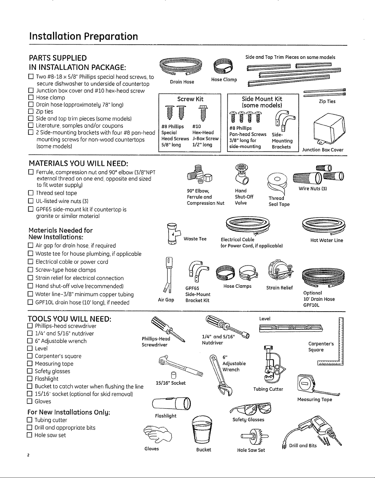
PARTSSUPPLIED
IN INSTALLATION PACKAGE:
rq Two #8-18 x 5/8" Phillipsspecial head screws,to
secure dishwasher to underside of countertop
[] Junction box cover and #10 hex-head screw
[] Hoseclamp
[] Drain hose(approximately 78"long)
[] Zip ties
[] Side and top trim pieces (some models}
[] Literature samples and/or coupons
[] 2 Side-mounting brackets with four #8 pan-head
mounting screws for non-wood countertops
Isomemodels}
MATERIALS YOU WILL NEED:
[] Ferrule, compression nut and 90 ° elbow (3/8"NPT
external thread on one end. opposite end sized
to fit water supplgt
[] Thread seal tape
[] UL-listed wire nuts (3}
[] GPF65 side-mount kit if countertop is
granite or similar materiel
Materials Needed for
New Installations:
[] Air gap for drain hose if required
[] Waste tee for house plumbing, if applicable
[] Electrical cable or power cord
[] Screw-tgpe hose clamps
[] Strain relief for electrical connection
[] Hand shut-off valve (recommended}
[] Water line-3/8" minimum copper tubing
[] GPFIOL drain hose (10' Iongl, if needed
Drain Hose
Screw Kit
gg ?
#8 Phillips #!0
Special Hex-Head
HeadScrews J-BOXScrew
518"long 112"long
90° Elbow, Hand
Ferruleand Shut-Off Thread
Compression Nut Valve SealTape
Waste Tee
GPF65 HoseClamps StrainRelief
Side-Mount
Air'Gap
B{_cket Kit
Side and Top Trim Pieces on some models
©
HoseClamp
Side Mount Kit
(some models)
#B Phillips
Pan-head Screws
3/8" long for
side-mounting
Electrical Cable
(or Power Cord, if applicable}
Side-
Mounting
Brackets
,===:=:======_
_==:==:=======
Zip Ties
Junction BoxCover'
Wire Nuts (3)
Hot Water Line
Optional
10' Drain Hose
GPF10L
TOOLS YOU WILL NEED:
[] Phillips-head screwdriver
[] 1/4" and 5/16" nutddver
[] 6" Adjustable wrench
[] Level
[] Carpenter's square
[] Heasuring tape
[] Safetg glasses
[] Flashlight
[] Bucket to catch water when flushing the line
[] !5/!6 socket (optional for skid removal)
[] Gloves
For New Installations Onlg:
[] Tubing cutter
[] Drill and appropriate bits
[] Hole saw set
Phill_
Screwdriver
15116"Socket \_nch
Flashlight
Gloves
Nutdriver
Bucket
Level
Carpenter's
Square
TubingCutter
Measuring Tape
Safetg Glasses
Hole Saw Set
Installation Preparation
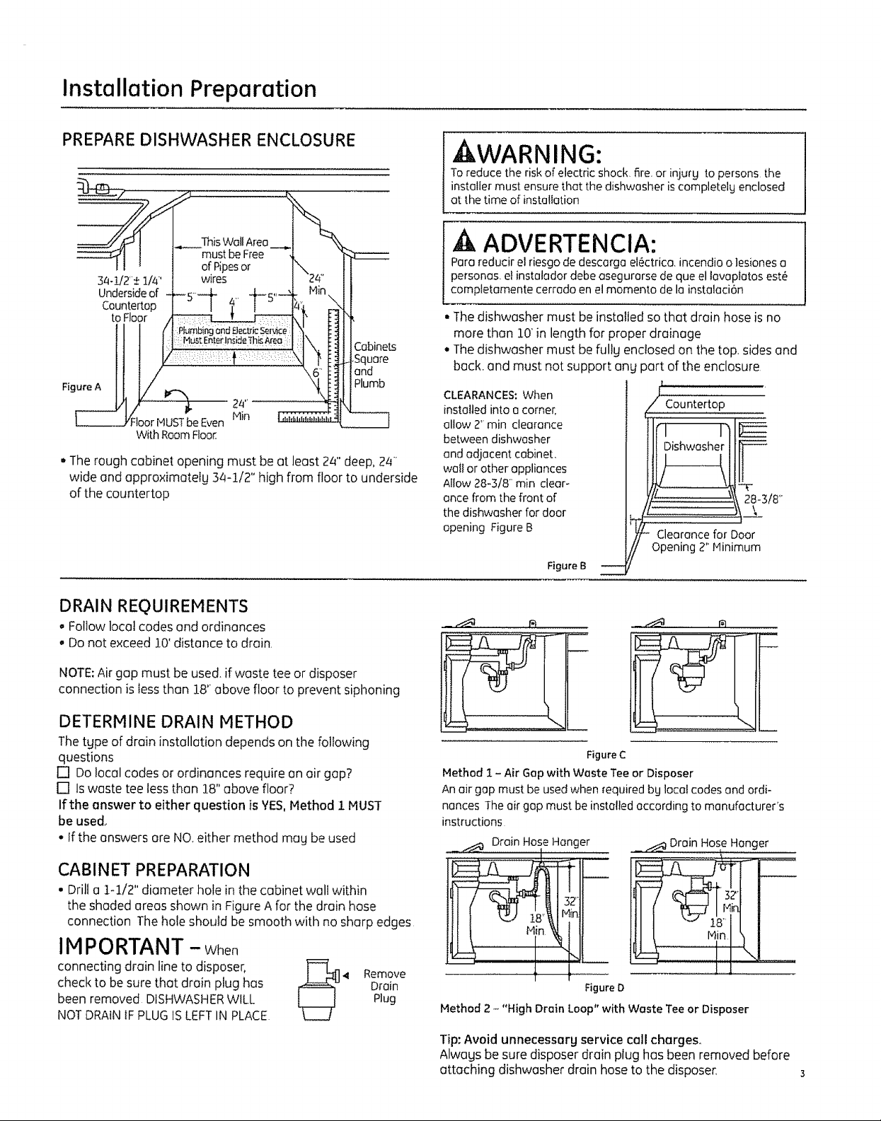
PREPARE DISHWASHER ENCLOSURE
ThisWallArea
34-1/2"± 1/4'
Undersideof
Countertop
to Floor
Square
and
Figure A
Even
With RoomFloor.
• Therough cabinet opening must be at least 24" deep,24"
wide and approximatelg 34-1/2" high from floor to underside
of the countertap
Plumb
kWARNING:
Toreduce the riskof electric shock fire or injurg to persons the
installer must ensure that the dishwasher iscompletelg enclosed
at the time of installation
ADVERTENCIA:
Para reducir el riesgo de descarga el6ctrica, incendio o ]esionesa
personas, et instalador debe asegurarse deque ellavaptatas est6
comptetamente cerrado en elmomenta de lainstalaci6n
• The dishwasher must be installed so that drain hose is no
more than 10' in length for proper drainage
° The dishwasher must be fully enclosed on the top. sides and
back. and must not support an!
CLEARANCES:When
installed into a corner,
allow 2" min clearance
between dishwasher
and adjacent cabinet,
wail or other appliances
Allow 28-3/8- rain clear-
ance from the front of
the dishwasher for door
opening Figure B
Figure B --
part of the enclosure
I,,, ,u,,
'l=-
' \F
f Dishwasher --_-8-3/8"
Clearance for Door
f -'
Opening 2" Minimum
DRAIN REQUIREMENTS
oFollow local codes and ordinances
° Do not exceed i0' distance to drain,
NOTE: Air gap must be used. if waste tee or disposer
connection is Jessthan 18' above floor to prevent siphoning
DETERMINE DRAIN METHOD
The type of drain installation depends on the following
questions
[] Do local codes or ordinances require on air gap?
[] Is waste tee less than 18" above floor?
If the answer to either question is YES,l'4ethod i MUST
be used.
• If the answers ore NO, either method may be used
CABINET PREPARATION
• Drill a ]-i/2" diameter hole in the cabinet wall within
the shaded areas shown in Figure A for the drain hose
connection The hole should be smooth with no sharp edges
IMPORTANT -When
connecting drain line to disposer, _Lff]
been removed DISHWASHER WILL Plug
check to be sure that drain plug has _-J 4 RemoveDrain
NOT DRAIN IF PLUG IS LEFTIN PLACE
Figure C
Method 1 - Air Gap with Waste Tee or Disposer
An air gap must be used when required bg locot codes and ordi-
nances The air gap must be installed according to manufacturer's
instructions
_ _ Drain HoseHanger
32"
J t[
Figure D
Method 2 - "High Drain Loop" with Waste Tee or Disposer
_.__ Drain Hose Hanger
o
!
Tip: Avoid unnecessarg service call charges.
Alwags besure disposer drain plug has beenremoved before
attaching dishwasher drain hoseto the disposer_
installation Preparation
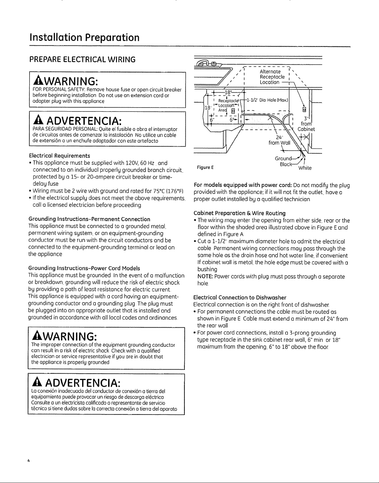
PREPARE ELECTRICAL WIRING
AWARNING:
FORPERSONAL SAFETY:Remove house fuse or open circuit breaker
beforebeginninginstallationDonotuseonextensioncordor
adapterplugwith thisappIiance
-A ADVERTENCIA:
PARASEGUR1DAD PERSONAL: Quite e_fusible o abra e! interruptor
decircuitosantesdecomenzarlainsta_aci6nNoutiliceuncable
deextensi6noun enchufeadaptadorconesteartefacto
Electrical Requirements
• Thisappliance must be suppliedwith 120V,60 Hz and
connected to an individual properlg grounded branch circuit.
protected bg a 15- or 20-ampere circuit breaker or-time-
detag fuse
• Wiring must be2 wire with ground and rated for 75°C(176°F)
• If theelectrical supplg does not meetthe above requirements.
call a licensed electrician before proceeding
Grounding Instructions-Permanent Connection
This appliance must be connected to a grounded metal.
permanent wiring sgstem, or an equipment-grounding
conductor must be run with the circuit conductors and be
connected to the equipment-grounding terminal or-lead on
the appliance
Grounding Instructions-Power Cord Models
Thisappliance must be grounded in the event of a malfunction
or breakdown, grounding will reduce the riskof electric shock
bg providing a path of least resistance for electric current,
Thisappliance isequipped with a cord having an equipment-
grounding conductor and a grounding plug Theplug must
be plugged into an appropriate outlet that is installed and
grounded inaccordance with all local codes and ordinances.
kWARNING:
The improper connection of the equipment grounding conductor
can resuR in a risk of electric shock Check with a qualified
electrician or service representative if gou ore in doubt that
the appliance is propertg grounded
I Receptacle _
" II Location\ ! ',
--41 ' Receptac!#_-l-1/2'DiaHolelMax _\\
, Am04a ' .... all
-\_-N _, Cabinet
24" i
fro
Figure E white
For models equipped with power cord: Do not modifg the plug
provided with the appliance; if it will not fit the outlet have a
proper outlet installedbg a qualified technician
Cabinet Preparation& Wire Routing
• Thewiring mag enter theopening from either side. rear or the
floor within the shaded area illustrated above inFigure Eand
defined in FigureA
° Cut a 1-1/2' maximum diameter hole to admit the electrical
cable Permanent wiring connections mag passthrough the
same holeas the drain hoseand hot water line.if convenient
If cabinet wall ismetal, the hole edge must be covered with a
bushing
NOTE:Power cords with plug must pass through aseparate
hole
Electrical Connection to Dishwasher
Electrical connection is on the right front of dishwashe[
• For permanent connections the cable must be routed as
shown in FigureE Cablemust extend aminimum of 24"from
the rear wall
• For power cord connections, installa ]-prong grounding
tape receptacle inthe sink cabinet rear wall,6" rain or 18"
maximum from the opening. 6" to 18"above the floor
ADVERTENCIA:
Laconexi6n inadecuada delconductor de conexi6n a tierra del
equipamiento puedeprovocar un riesgode descarga eI6ctrica
Consultea un electddsta calificadoorepresentante deservicio
t6cnicositiene dudassabre la correcto conexi6n a tier_adelaparato
1
Installation Preparation
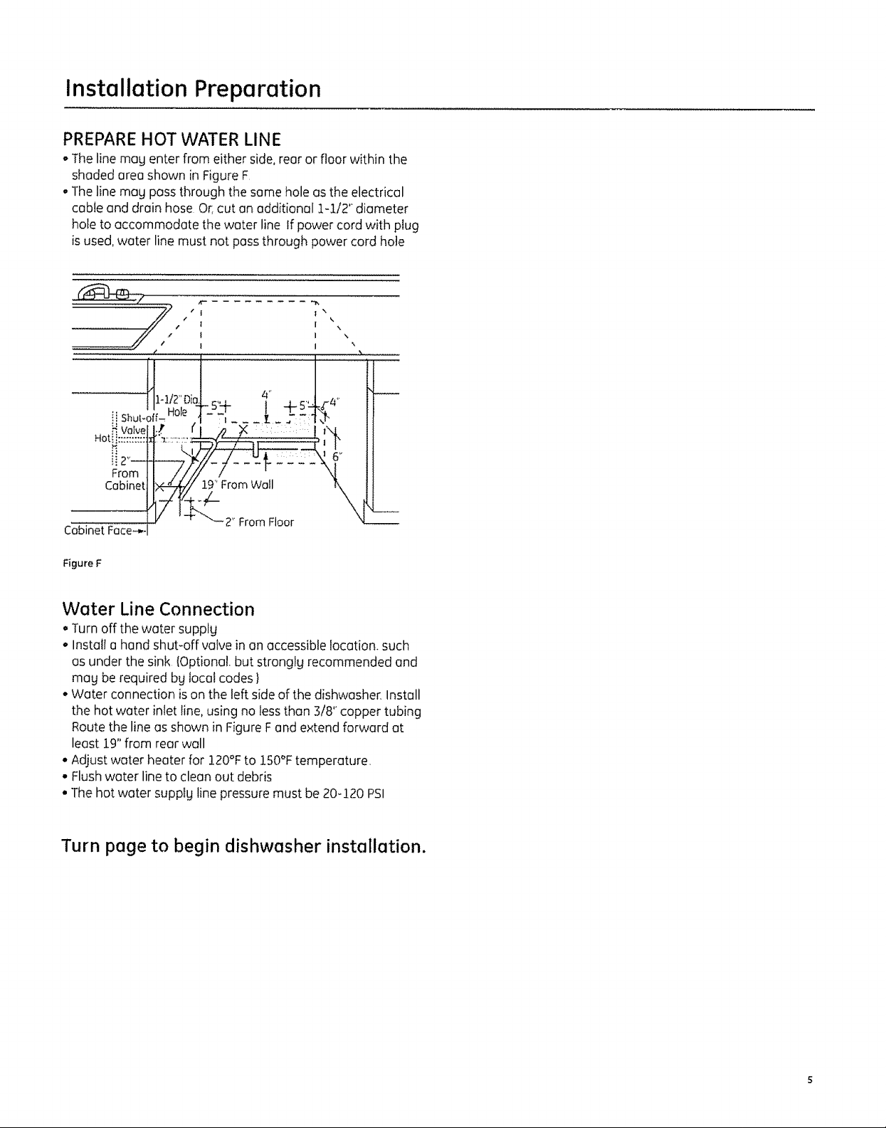
PREPARE HOT WATER LINE
° The line mag enter from either side, rear or floor within the
shaded area shown in Figure F
• The line mag pass through the some hole as the electrical
cable and drain hose OF.cut on additional 1-1/2" diameter
hole to accommodate the water line If power cord with plug
is used, water line must not pass through power cord hole
," _ [\
€
| I .
........... #'
ii Shutooff-Hole
Valve
Hot_i::::::::::
iiZ'--
From
Cabinet
Cabinet Face--..
H1-I/2" Dic
I I '
\,,,\
Figure F
Water Line Connection
° Turn off the water supply
* Install a hand shut-off valve in an accessible location, such
as under the sink (Optional. but strongkj recommended and
mag be required bg local codes 1
, Water connection is on the left side of the dishwasher. Install
the hot water inlet line, using no less than 3/8" copper tubing
Route the line as shown in Figure Fand extend forward at
least 19" from rear wall
, Adjust water heater for 120°F to 150°F temperature.
- Flush water line to clean out debris
° The hot water supplg line pressure must be 20-120 PSI
Turn page to begin dishwasher installation.
Dishwasher Installation
CAUTION:
Do not remove wood base until gou are readg to instaIl the
dishwasher, The dishwasher will tip overwhen the door isopened
if base is removed
PRECAUCION:
NOquite labasedemadera haste que est_ listo pare instatarel
tavaplatos Sisequite la base ellavaplatos sevolcar6cuando se abra
la puerto
STEP 1: PREPARATION
Locate the items in the installation package and set aside for
use in the listed steps:
• Screw kit - Steps 5 or 18 and 15
• Junctionbox cover- Step5 or 18
• Drainhose and clamp - Step 7
• DFainhose hanger- Step 17
•Trim pieces(some models)- Step 11
• Owner's Hanual - Steps 19 and 22
• Product Samples and/or coupons - Step 22
• Side-mount kit - Step 12
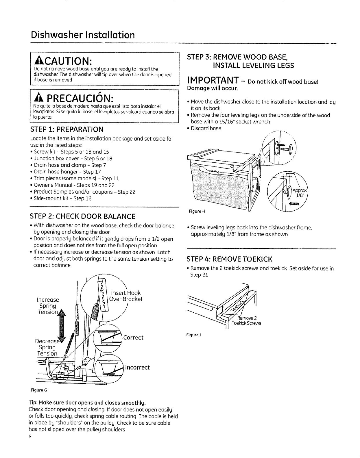
STEP 2: CHECK DOOR BALANCE
• With dishwashe_ on the wood base check the door balance
bg opening and closing the door
• Door is properlg balanced if it gentlg drops from a 1/2 open
position and does not rise flom the full open position
o if necessarg increase or decrease tension as shown Latch
door and adjust both springs to the same tension setting to
correct balance
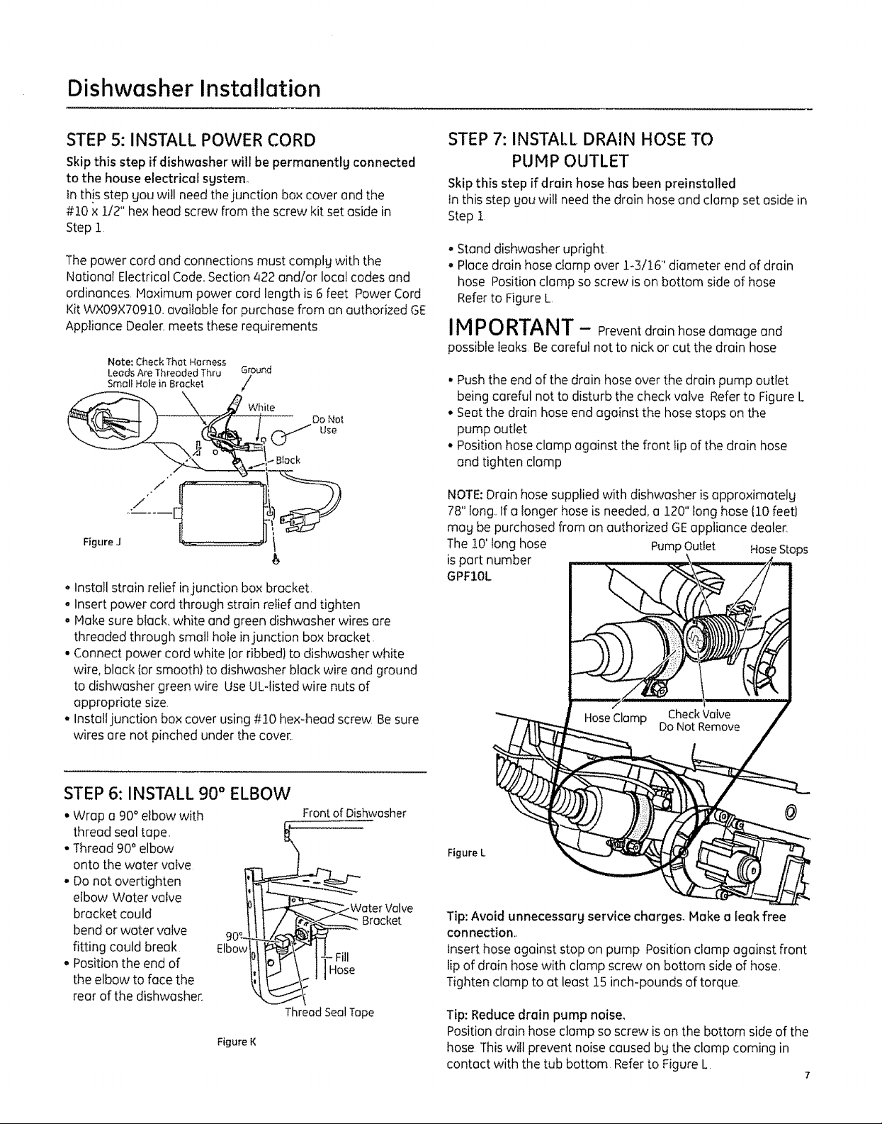
STEP 3: REMOVE WOOD BASE,
INSTALL LEVELING LEGS
IMPORTANT - Donotkickoffwoodbase!
Damage will occur'.
, Hove the dishwasher close to the installation location and lay
it on its back
• Remove the four leveling legs on the underside of the wood
base with o 15/16" socket wrench
• Discard base
l_[_ tAPr
Figure H
° Screw leveling legs back into the dishwasher frame
approximately 1/8" from frame as shown
STEP 4: REMOVE TOEKICK
• Remove the 2 toekick screws and toekick Set aside for use in
Step 21
insert Hook
Increase
Over Bracket
Spring
Tension
Decrees
Correct
Spring
Tension
incorrect
FigureG
Tip: Make sure door' opens and closes smoothlgo
Check door opening and closing If door does not open easilg
or falls too quicklg, check spring cable routing The cable is held
in place bg 'shoulders" on the pulteg Check to be sure cable
has not slipped over the pulleg shoulders
6
Figure I
Dishwasher Installation
STEP 5: INSTALL POWER CORD
Skip this step if dishwasher will be permanentlg connected
to the house electrical sgstemo
In this step you will need the junction box cover end the
#20 x !/2" hex heed screw from the screw kit set aside in
Step 1
The power cord and connections must comply with the
Notional Electrical Code,Section422 end/or local codes and
ordinances, Haximum power cord length is 6 feet Power Cord
Kit WX09X70910.available for purchasefrom an authorized GE
Appliance Dealer.meetsthese requirements
Note: Ci_eck That Harness
Leads Are Threaded Thru Ground
Smal_ Ha_e in Bracket /
oInstall strain relief injunction box bracket,
• Insert power cord through strain relief and tighten
• Hake sureblack, white and green dishwasher wiresare
threaded through small hole injunction box bracket
• Connect power cord white (orribbed} to dishwasher white
wire, black {orsmooth) to dishwasher block wire end ground
to dishwasher green wire UseUL-listed wire nutsof
appropriate size,
- Instaltjunction box cover using #t0 hex-head screw Besure
wires are not pinched under the cover
STEP 7: INSTALL DRAIN HOSE TO
PUMP OUTLET
Skipthis step if drain hose has been preinstalled
tn this step gou will needthe drain hose and clamp set aside in
Step 1
° Stand dishwasher upright
• Place drain hoseclamp over 1-3/16" diameter end of drain
hose Positionclamp so screw is on bottom side of hose
Referto FigureL
IM P0 RTANT - Preventdrainhosedamage end
possible leaks Becareful not to nickor cut the drain hose
• Pushthe end of the drain hose over the drain pump outlet
being careful not to disturb the check valve Referto Figure L
• Seatthe drain hose end against the hose stops on the
pump outlet
• Positionhose clump against the front tipof the drain hose
and tighten clamp
NOTE:Drain hose supplied with dishwasher is approximatelg
78"long, Ifa longer hoseis needed,a 120"long hose 110feetl
mag be purchased from anauthorized GEappliance dealer.
The10' long hose PumpOutlet HoseStops
is part number
GPF10L
STEP 6: INSTALL 90 ° ELBOW
• Wrap a 90° elbow with
thread seal tape,
• Thread 90° elbow
onto the water valve
o Donot overtighten
elbow Water valve
bracket could
bend orwater valve
fitting could break Elbow
• Positionthe end of
the elbow to facethe
rear of the dishwashe_
Figure K
Front of Dishwasher
Weter Valve
Thread Seal Tope
Bracket
Figure L
Tip: Avoid unnecessarg service charges. Make a leak free
connection,,
Insert hose against stop on pump Position clamp against front
lip of drain hosewith clampscrew on bottom side of hose,
Tighten clamp to at least 15inch-pounds of torque
Tip: Reducedrain pump noise,
Position drain hose clamp so screw ison the bottom side of the
hose This will prevent noisecaused bg the clamp coming in
contact with the tub bottom Referto Figure L
7
Dishwasher Installation
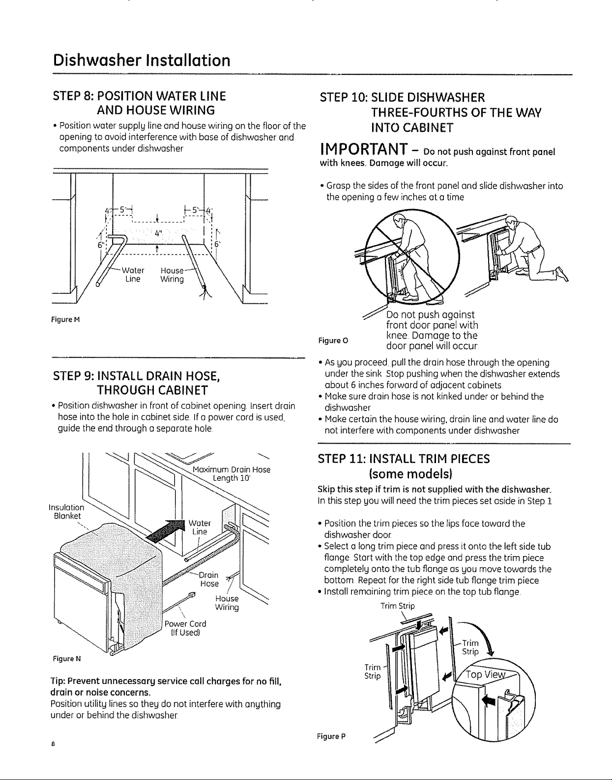
STEP8: POSITION WATER LINE
AND HOUSE WIRING
• Positionwater supply line and housewiring on the floor of the
opening to avoid interference with base of dishwasher end
components under dishwasher
Line Wiring
Figure M
STEP9: INSTALL DRAIN HOSE,
THROUGH CABINET
* Position dishwasher in front of cabinet opening, Insert drain
hose into the hole in cabinet side, Ifa power cord isused
guide the end through o separate hole,
STEP 10: SLIDE DISHWASHER
THREE-FOURTHS OF THE WAY
INTO CABINET
IMPORTANT - Donotpushagainstfrontpanel
with knees. Damage will occur.
• Grasp the sidesof the front panel and slidedishwasher into
the opening a few inches at a time
Do not push against
front door panel with
Figure O
• Asyou proceed, pulIthe drain hose through the opening
under the sink Stop pushing when the dishwasher extends
about 6 inches forward of adjacent cabinets
• Hake suredrain hoseis not kinked under or behind the
dishwasher
° Hake certain the housewiring, drain tine and water' tine do
not inLerferewith components under dishwasher
knee Damage to the
door panel will occur
Maximum Drain Hose
Length t0'
Insulatior
Blanket
Hose
i
House
Wiring
Power Cord
[IfUsed)
Figure N
Tip: Prevent unnecessarg service call chargesfor no fill,
drain or noise concerns°
Position utilitg lines so theg do not interfere with angthing
under or behind the dishwasher
STEP 11: INSTALL TRIM PIECES
{some models}
Skipthis step if trim is not supplied with the dishwasher.
Inthis step you will need the trim pieces set aside in Step I
• Position thetrim pieces so the lips face toward the
dishwasher doe{
• Selecta long trim pieceand pressit onto the left sidetub
flange Start with the top edge and press the trim piece
completetg onto the tub flange as you move towards the
bottom Repeat for the right sidetub flange trim piece
° Install remaining trim piece on the top tub flange.
TrimStrip
Figure P
Dishwasher Installation
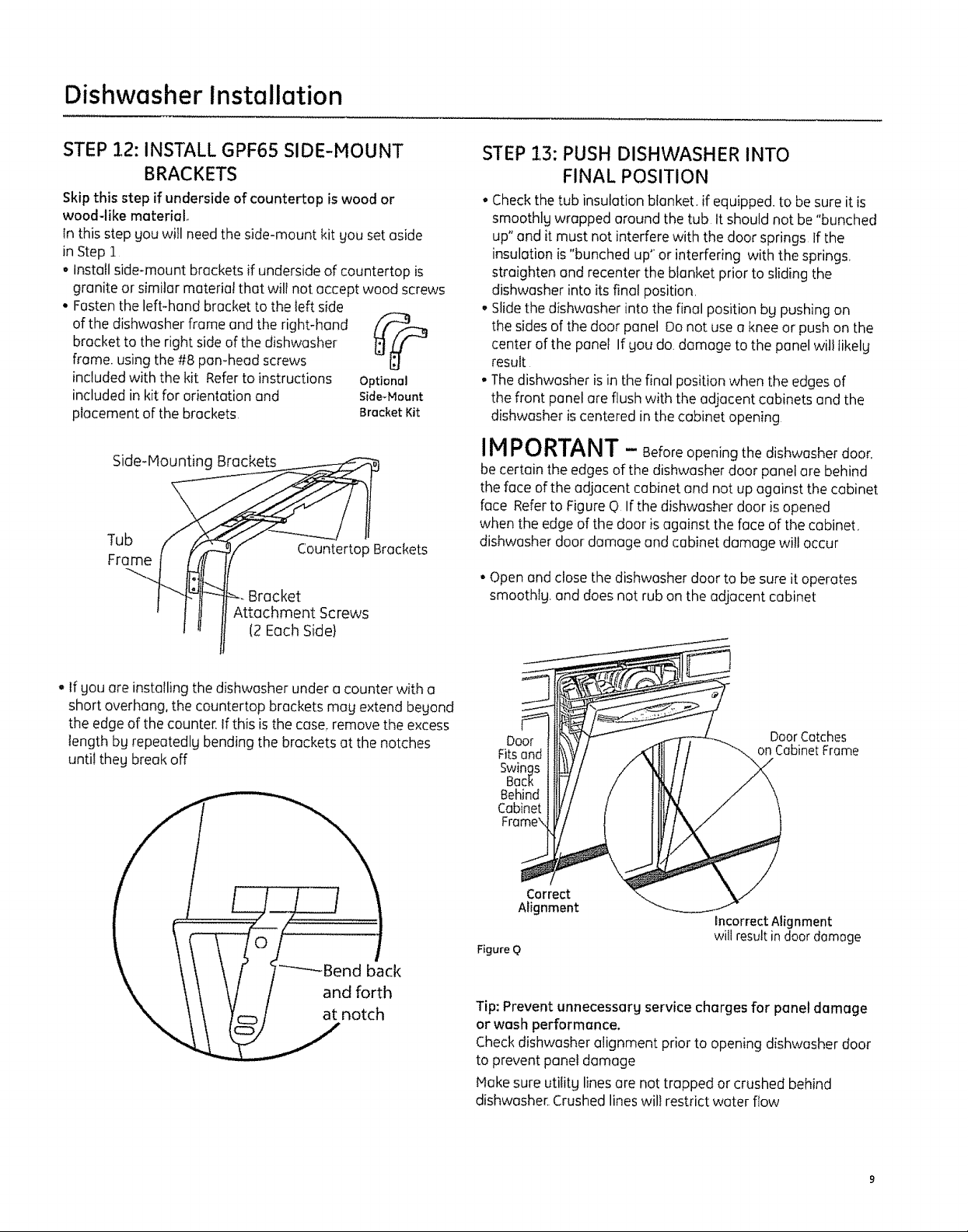
STEP 12: INSTALL GPF6S SIDE-MOUNT
BRACKETS
Skip this step if underside of countertop is wood or
woodqike material
in this step gou will need the side-mount kit you set aside
in Step 1
° Install side-mount brackets if underside of countertop is
granite or similar material that will not accept wood screws
• Fasten the left-hand bracket to the left side
of the dishwasher frame and the right-hand
bracket to the right sideof the dishwasher
frame, using the #8 pan-head screws
included with the kit Referto instructions
included in kit for orientation and
placement of the brackets
Side-Mounting Brackets
Tub
Frame
Bracket
Attachment Screws
12Each Side}
Countertop Brackets
Optional
Side-Mount
Bracket Kit
STEP -!3: PUSH DISHWASHER INTO
FINAL POSITION
• Checkthe tub insulation blanket, if equipped, to be sure it is
smoothlg wrapped around the tub it should not be "bunched
up" and it must not interfere with the door springs If the
insulation is"bunched up" or interfering with the springs.
straighten and recenter the blanket prior to sliding the
dishwasher into its final position.
• Slidethe dishwasher into the final position bg pushing on
the sides of the door panel Donot usea kneeor push on the
center of the panel If SOUdo. damage to the panelwill iikelg
result
° The dishwasher isin the final position when the edgesof
the front panelare flush with the adjacent cabinets and the
dishwasher iscentered in the cabinet opening
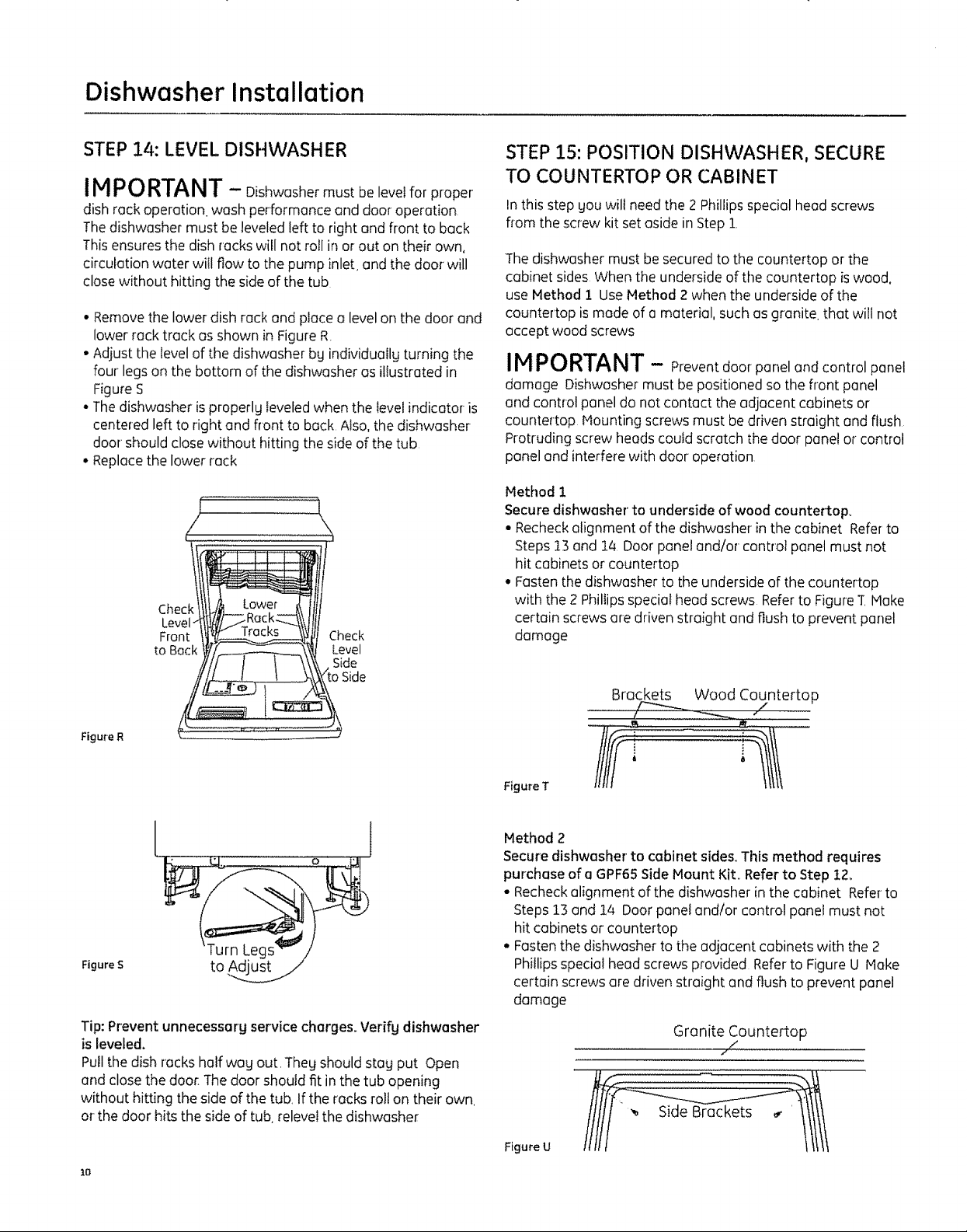
IMPORTANT - Beforeopeningthedishwasherdoor.
be certain the edgesof the dishwasher door panel are behind
the face ofthe adjacent cabinet and not up against the cabinet
face Referto Figure C)If the dishwasher door is opened
when the edge of the door is against the face of the cabinet.
dishwasher door damage end cabinet damage will occur
• Open andclose the dishwasher door to be sure it operates
smoothtg, and doesnot rub on the adjacent cabinet
- If Souore installing the dishwasher under o counter with o
short overhang, the countertop brackets mag extend begond
the edge of the counter. If this is the case.remove the excess
length bg repeatedly bending the brackets at the notches
until theg break off
!
t !/ / andforth
\
i _____.j nOtch
Door
Fitsand
Swings
Back
Behind
Cabinet
Correct
Alignment
Figure O
Tip: Prevent unnecessarg service charges for panel damage
or wash performance.
Check dishwasher alignment prior to opening dishwasher door
to prevent panel damage
Hake sure utititg lines are not trapped or crushed behind
dishwasher Crushed lines wilt restrict water flow
Incorrect Alignment
wilt result in door damage
DoorCatches
on Cabinet Frame
Dishwasher Installation
STEP 14: LEVEL DISHWASHER
IMPORTANT - Dishwashermust be level forproper
dishrockoperationwash performanceend dooroperation
Thedishwashermustbe leveledlefttorightand fronttobeck
This ensures the dish rackswill not roll in or out on their own,
circulation water witlflow to the pump inlet, and the door will
close without hitting the sideof the tub
• Remove the lower dish rack and place o level on the door and
lower rock track as shown in Figure R
• Adjust the level of the dishwasher by individually turning the
four legs on the bottom of the dishwasher es illustrated in
Figure S
• The dishwasher is properly leveled when the level indicator is
centered left to right end front to beck Also, the dishwasher
door should close without hitting the side of the tub
• Replace the lower rack
/ \
che lI
Level_
to Back _/f,_._._1\_, Level
//// / _ \\_,_j Side
STEP !5: POSITION DISHWASHER, SECURE
TO COUNTERTOP OR CABINET
Inthis step gouwill needthe 2 Phillips special head screws
flom the screw kit set aside in Step 1,
The dishwasher must besecured to the countertop or the
cabinet sides When the underside of the countertop iswood,
use Method i Use Method 2when the underside of the
countertop ismode of a material, such as granite, that will not
accept wood screws
IMPORTANT - Prevent door panel and control panel
damage Dishwasher must be positioned so the flont panel
and control panel do not contact the adjacent cabinets or
countertop Mounting screws must be driven straight and flush
Protruding screw heads could scratch the door panel or"control
paneland interfere with door operation
Method 1
Secure dishwasher to underside of wood countertop_
• Recheck alignment of the dishwasher in the cabinet Refer to
Steps 13 and 14 Door panel and/or control panel must not
hit cabinets or countertop
• Fasten the dishwasher to the underside of the countertop
with the 2 Phillips special heed screws Refer to Figure T Make
certain screws ore driven straight and flush to prevent panel
damage
Side
Figu_"eR
l
Figure S
Tip: Prevent unnecessary service charges. Verify dishwasher
is leveled.
Pull the dish rocks half wag out, Thegshould stag put Open
and closethe door. Thedoor should fit in the tub opening
without hitting the side of the tub, Ifthe rocks roll on their own.
or the door hits the sideof tub relevel the dishwasher
Io
1
BrQckets Wood Countertop
_ _ ./ .........
Figure T
Method 2
Secure dishwasher to cabinet sides_ This method requires
purchase of a GPF65 Side Mount Kit_ Refer to Step 12_
• Recheck alignment of the dishwasher in the cabinet Refer to
Steps 13 and 14 Door penet and/or control ponet must not
hit cabinets or countertop
• Fasten the dishwasher to the adjacent cabinets with the 2
Phillips special head screws provided Refer to Figure U Make
certain screws are driven straight and flush to prevent panel
damage
Granite Countertop
/ /
Figure U