

GE PDW7300N10BB, PDW7300N10CC, PDW7300N10WW, PDW7300N15BB, PDW7300N15CC Installation Guide
...
Installation
Built-In
Instructions
l If you have questions,call 800.GE.CARES(800.432.2737)or visit ourwebsite at:www.ge.com I
BEFORE YOU BEGIN
Read these instructions completely and
carefully.
IMPORTANT- The dishwasher
MUST be installed to allow for future removal from the
enclosure if service is required.
If you received a damaged dishwasher, you should
immediately contact your dealer or builder.
Dishwasher
IMPORTANT- Observe all
governing codes and ordinances.
• Note to Installer- Be sure to leave these instructions
for the consumer's and local inspector's use.
• Note to Consumer- Keep these instructions with your
Owner's Manual for future reference.
• Skill Level - Installation of this dishwasher requires
basic mechanical, electrical and plumbing skills.
Proper installation isthe responsibility ofthe
installer. Product failure due to improper installation
is not covered under the GEAppliance Warranty.
See warranty information.
• Completion Time - 1 to 3 Hours. New installations
require more time than replacement installations.
Optional Accessories - See the Owner's Manual for
available custom panel kits.
FOR YOUR SAFETY
Read and observe all CAUTIONS and WARNINGS
shown throughout these instructions. While performing
installations described in this booklet, gloves, safety
glasses or goggles should he worn.
READ CAREFULLY.
KEEP THESE INSTRUCTIONS.
Installation Preparation
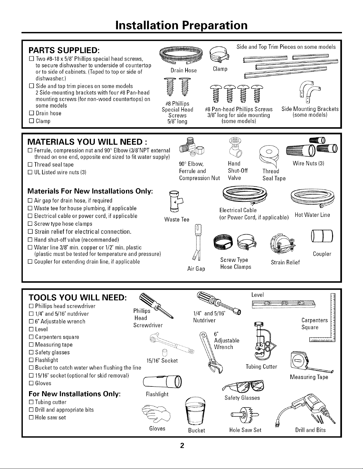
PARTS SUPPLIED:
[] Two#8-18x 5/8"Phillips special headscrews,
to secure dishwasher to underside of countertop
orto side of cabinets.(Tapedto top or side of
dishwasher.)
[] Side and top trim pieceson some models
2 Side-mounting brackets with four #8Pan-head
mounting screws (for non-wood countertops) on
some models
[] Drainhose
[] Clamp
Special Head
MATERIALS YOU WILL NEED :
[] Ferrule,compression nut and 90° Elbow(3/8"NPTexternal
thread on one end,opposite end sizedto fit water supply)
[] Thread sealtape
[] ULListed wire nuts (3)
Materials For New Installations Only:
[] Air gapfor drain hose, if required
[] Waste tee for house plumbing,if applicable
[] Electrical cable or power cord, if applicable
[] Screwtype hose clamps
[] Strain relief for electrical connection.
[] Handshut-off valve(recommended)
[] Water line 3/8"rain.copper or 1/2" rain.plastic
(plastic must betested for temperature andpressure)
[] Couplerfor extending drain line, if applicable
Waste Tee
©
Drain Hose
#8Phillips
Screws
5/8"long
90° Elbow, Hand
Ferruleand Shut-Off
CompressionNut Valve
Air Gap HoseClamps
Clamp
#8 Pan-head Phillips Screws
3/8"long for side mounting
Side and TopTrim Pieces on some models
Side Mounting Brackets
(some models)
(somemodels)
Wire Nuts (3)
Thread
Seal Tape
Electrical Cable
(or Power Cord,if applicable) HotWater Line
Coupler
Screw Type Strain Relief
TOOLS YOU WILL NEED:
[] Phillips head screwdriver
[] 1/4"and 5/16"nutdriver Ph
[] 6"Adjustable wrench
[] Level
[] Carpenters square _,_ _'_ 6"
[] Measuring tape :--_; - , \\\\ \Air, rich
[] Safety glasses _ ......._%
[] Flashlight 15/16"Socket
[] Bucket to catch water when flushing the line
[] 15/16"socket (optional for skid removal)
[] Gloves
For New Installations Only:
[] Tubingcutter
[] Drill and appropriate bits
[] Hole saw set
Head
Screwdriver
_!_-_:--_- \\\\ AdjustabIe
Flashlight
Gloves Bucket
Nutdriver
Safetv Glasses
Level
TubingCutter
HoleSaw Set
Carpenters
Square
Measuring Tape
Drill and Bits

Installation Preparation
PREPARE DISHWASHER ENCLOSURE
ThisWallArea
351/2"_+1/4"
Undersideof
Countertop
toFloor
FigureA
FloorMUSTbeEvenMin.
WithRoomFloor
• The rough cabinet opening must be at least 24"deep,
24"wide and approximately 34-1/2" high from floor to
underside of the countertop.
of
Cabinets
_Square
and
Plumb
WARNING:
Toreduce the risk of electric shock,fire, or injury to
persons,the installer must ensure that the dishwasher is
completely enclosed at the time of installation.
• The dishwasher must be installed so that drain hose is
no more than 10' in length for proper drainage.
• The dishwasher must be fully enclosed on the top,
sides and back, and must not support any part of the
enclosure.
CLEARANCES:When
installed into a corner,
allow 2" rain.clearance
between dishwasher and
adjacent cabinet, wall or
other appliances. Allow
28-3/8"rain. clearance
from the front of the
dishwasher for door
opening. Figure B
FigureB
I
Counteltop
Door
Opening2" Minimum
DRAIN REQUIREMENTS
• Follow local codes and ordinances.
• Do not exceed 10' distance to drain.
NOTE: Air gap must be used, if waste tee or disposer
connection is less than 18" above floor to prevent
siphoning.
DETERMINE DRAIN METHOD
The type of drain installation depends on the following
questions.
[] Do local codes or ordinances require an air gap?
[] Is waste tee less than 18"above floor?
If the answer to either question is YES, Method 1 MUST
be used.
• If the answers are NO, either method may be used.
CABINET PREPARATION
• Drill a1-1/2" din. hole in the cabinet wall within the
shaded areas shown in Figure A for the drain hose
connection. The hole should be smooth with no sharp
edges.
IMPORTANT-when
connecting drain line to disposer, _-r-r_ 4-- Remove
checkto be sure that drain plug has i_ - Hopper
been removed. DISHWASHER WILL I-r-----TI Plug
NOT DRAIN IF PLUG IS LEFTIN PLACE._
FigureC
Method 1 - Air Gap with Waste Tee or Disposer
An air gap must be usedwhen required by local codes and ordinances.
The air gapmust be installed according to manufacturer's instructions.
m
m
I_ Mlin t_r
FigureD
Method 2 - "High Drain Loop" with Waste Tee or Disposer
n.
\
Note: Avoid unnecessary service call charges. Always be
sure disposer drain plug has been removed before attaching
dishwasher drain hose to the disposer.

Installation Preparation
PREPARE ELECTRICAL WIRING
FORPERSONAL SAFETY:Remove
house fuse or open circuit breaker
before beginning installation, Do not
use an extension cord or adapter plug
with this appliance.
/ _- Alternate -_\
/ I I \
/ Receptacle j \
/_ II Location_ ",
._z_ __Rece_ta_l-1/2" Din.Hole(Max.) _
)Ii":--L;:atl/°n_"i ;J - _ .... -- _ H
Electrical Requirements
• This appliance must be supplied with 120V,60 Hz., and
connected to an individual properly grounded branch
circuit, protected by a 15 or 20ampere circuit breaker
or time delay fuse.
• Wiring must be 2 wire with ground and rated for 75°C
(176°F).
• If the electrical supply does not meetthe above
requirements, call a licensed electrician before
proceeding.
Grounding Instructions-Cable Direct
This appliance must be connected to agrounded metal,
permanentwiring system, or an equipment grounding
conductor must be run with the circuit conductors and
be connected to the equipment grounding terminal or
lead on the appliance.
Grounding Instructions-Power Cord Models
This appliance must be grounded. In the event of a
malfunction or breakdown, grounding will reduce the
risk of electric shock by providing a path of least resis-
tance for electric current. This appliance is equipped
with a cord having an equipment grounding conductor
and a grounding plug. The plug must be plugged into an
appropriate outlet that is installed and grounded in
accordance with all local codes and ordinances.
The improper connection ofthe equip-
ment grounding conductor can result in
a risk of electric shock. Check with a
qualified electrician or service repre-
sentative if you are in doubt that the
appliance is properly grounded.
'_:'_X \Cabinet
II/ 24"
FigureE White
For models equipped with power cord: Do not modify the
plug provided with the appliance; if it will not fit the outlet,
have a proper outlet installed by a qualified technician.
Cabinet Preparation & Wire Routing
• The wiring may enter the opening from either side, rear
orthe floor within the shaded area.
• Cut a 1-1/2"max. dia. hole to admit the electrical cable.
Cable direct connections may pass through the same
hole as the drain hose and hotwater line, if convenient.
If cabinetwall is metal, the hole edge must be covered
with a bushing. NOTE: Power cords with plug must pass
through a separate hole.
Electrical Connection to Dishwasher
Electrical connection is on the right front of dishwasher.
• For cable direct connections the cable must be routed
as shown in Figure E. Cable must extend a minimum of
24"from the rear wall.
• For power cord connections, install a 3-prong grounding
type receptacle in the sink cabinet rear wall, 6"min. or
18"max. from the opening, 6" to 18"above the floor.
4
 Loading...