


GE GSD6300J10BB, GSD6300J10WW, GSD6660G10SS, PDW7712N10BB, PDW7712N10SS Installation Guide
...
Installation
Built-In
Dishwasher
Instructions
l If you have questions,call 800-GECARESor visit our website at: www.GEAppliances.com I
BEFORE YOU BEGIN
Read these instructions completely and carefully.
•IMPORTANT - C.,se,,'e.Ug,,,'e,',,i,,g
codes and ordinances.
• Note to Installer - Be sure to leave these instruc-
ti(ms for the consumer's and local inspector's use.
• Note to Consumer - Keep these instructions with
your (-)wiper's Manual fi)r fllture retbrei_ce.
• Skill Level - Installation of this dishwasher requires
basic mechanical and electrical skills. Proper installa-
tion is the responsibility of the installer. Product failure
due to improper installation is not covered under the
GE Appliance Waxranty.
• Completion Time - 1 to 3 Hours, New installations
require m ore tim e than replacement installation s.
•IMPORTANT - Thedish,,'.she,MUST_,e
installed to alhm tot fllture remoxal fl'om the enclo-
sure if serxice is required.
If vou receixed a damaged dislmasher, you should
immediateh' contact your dealer or builder.
Optional Accessories - See the o,vne,"s m.n_,.1
fin" axailable custom panel kits.
FOR YOUR SAFETY
Read and observe all CAUTIONS and WARNINGS
shown throughout these instructions. While performing
installations described in this booklet, gloves, safety
glasses or goggles should be worn.
READ CAREFULLY.
KEEP THESE INSTRUCTIONS.
Installation Preparation
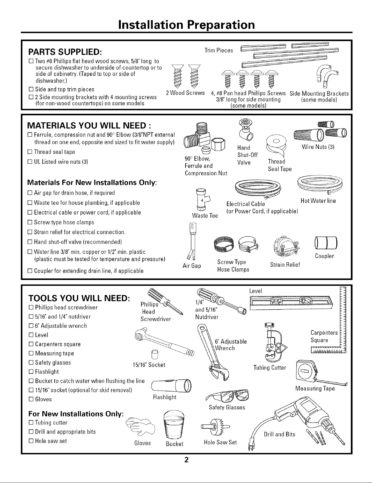
PARTS SUPPLIED:
[] Two#8 Phillips flat head wood screws, 5/8"long to
secure dishwasher to underside of countertop orto
side of cabinetry. (Tapedtotop or side of
dishwasher.)
[] Side and top trim pieces
[] 2 Side mounting bracketswith 4 mounting screws
(for non-wood countertops) on some models
2Wood Screws
MATERIALS YOU WILL NEED :
[] Ferrule,compression nut and 90° Elbow(3/8"NPTexternal
thread on one end,opposite end sizedto fit water supply)
[] Thread sealtape
[] ULListed wire nuts (3)
Materials For New Installations Only:
[] Air gap for drainhose,if required
[] Waste tee for house plumbing,if applicable
[] Electrical cable or power cord, if applicable
[] Screwtype hose clamps
[] Strain relieffor electrical connection.
[] Handshut-off valve (recommended)
[] Water line 3/8"rain.copper or 1/2" rain.plastic
(plastic must betested for temperature and pressure)
[] Couplerfor extending drain line, if applicable
Trim Pieces
4,#8 Pan head Phillips Screws Side Mounting Brackets
3/8"long for side mounting (some models)
(somemodels)
_@ _td__0ff
90° Elbow, Valve Thread
Ferrule and SealTape
Compression Nut
Electrical Cable
Waste Tee
Air Gap
(or Power Cord,if applicable)
Screw Type Strain Relief
Hose Clamps
Wire Nuts (3)
Hot Water line
Coupler
TOOLS YOU WILL NEED:
[] Phillips head screwdriver
[] 5/16"and 1/4" nutdriver
[] 6"Adjustable wrench
[] Level
[] Carpenters square
[] Measuring tape
[] Safety glasses
[] Flashlight
[] Bucketto catch water when flushing the line
[] 15/16"socket (optional for skid removal)
[] Gloves
For New Installations Only:
[] Tubingcutter
[] Drill and appropriate bits
[] Hole saw set
15/16"Socket
Gloves
Screwdriver
Flashlight
Bucket
2
and 5/16"
Nutdriver
Safety Glasses
Hole Saw Set
6"Adjustable
Wrench
Level
Carpenters
Square
TubingCutter
Measuring Tape
Drill and Bits
Installation Preparation
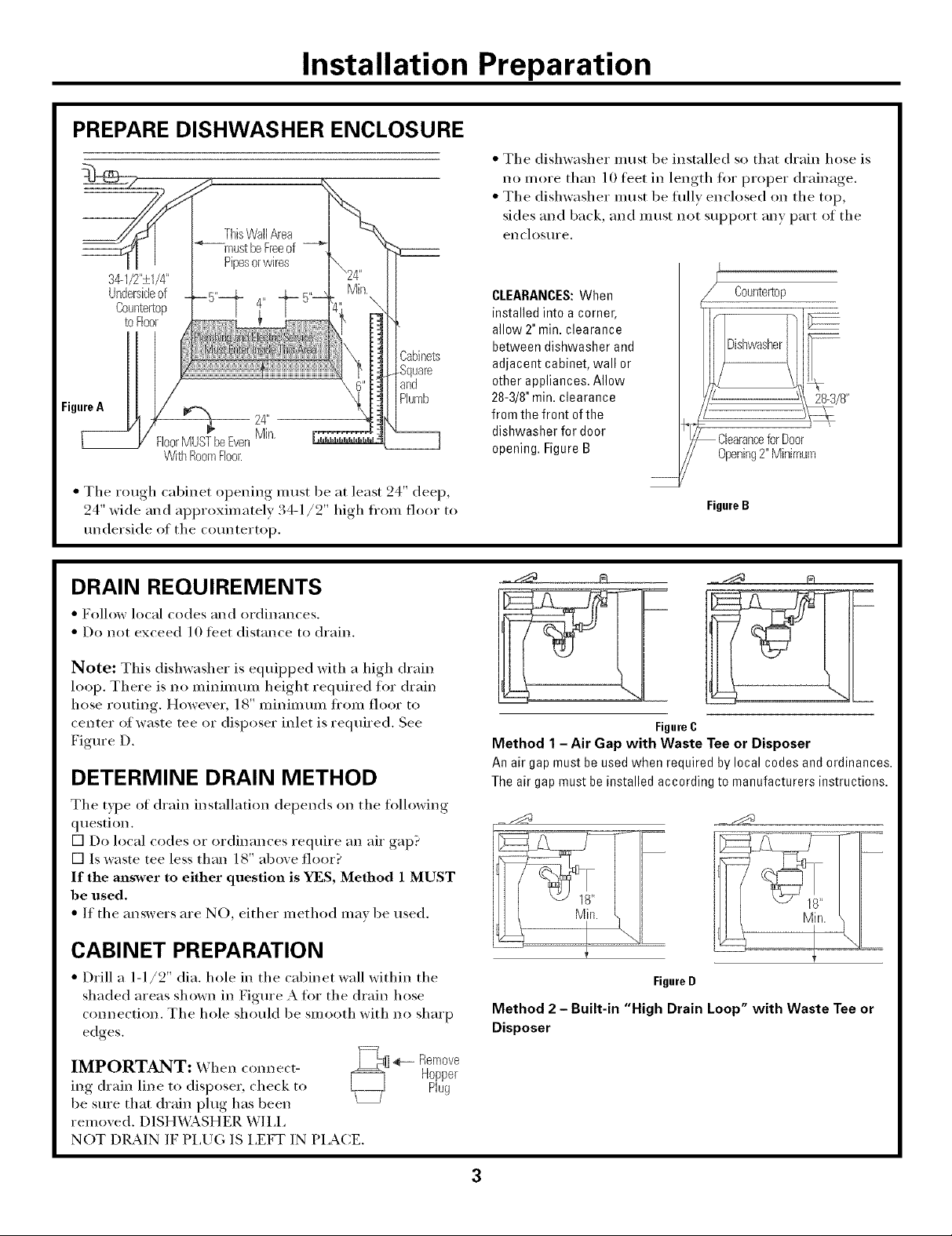
PREPARE DISHWASHER ENCLOSURE
34--I/2"_+I/4"
Undersideof
Counter'[op
toFloor
Figure[_A _//_
ThisWallArea
Pipesorwires
FloorMUSTbeEven
WithRoomFloor.
of
3abinets
Square
and
Plumb
24"
Min,
• The dishwasher must be installed so that drain hose is
no m ore than 10 tibet in length for proper drainage.
• The dishwasher must be fifllv enclosed on the top,
sides and back, mad must not support may part of the
enclostlre,
I
CLEARANCES:When
installed into a corner,
allow 2" min. clearance
between dishwasher and
adjacent cabinet, wall or
other appliances. Allow
28-3/8"rain. clearance
from the front of the
dishwasher for door
opening. Figure B
Countertop
{ - 28-3/8"
• The rough cabinet opening must be at lea,'t 24 deep,
24" _i(le and approximately : 4-1/2 high fl'om floor to
underside of the countertop.
DRAIN REQUIREMENTS
• Follov, local codes and ordinances.
• Do not exceed 10 ti_et (listance to drain.
Note: This dishwasher is equipped with a high drain
loop. There is no minimum height required for drain
hose routing. Howevei, 18" illinillltllll ti'Olll f]ooi" to
center of waste tee or disposer inlet is reqtfired. See
Figure D.
DETERMINE DRAIN METHOD
The type of drain installation depends on the following
question.
[] Do local codes or ordinances require an air gap?
[] Is waste tee less than 18" above floor?
If the answer to either question is YES, Method 1 MUST
be used.
• If the answers are NO, either method may be used.
FigureB
FigureC
Method 1 - Air Gap with Waste Tee or Disposer
An air gap must be used when required by local codesand ordinances.
The air gap must be installed according to manufacturers instructions.
CABINET PREPARATION
• Drill a 1-1/2" dia. hole in the cabinet wall within the
shaded areas shown in Figure A fin" the drain hose
connection. The hole should be smooth with no sharp
edges.
IMPORTANT: When connect-
ing drain line to disposei, check to
be sure that drain plug has been
removed. DISH_&SHER WILL
NOT DRAIN IF PLUG IS LEFT IN PLACE,
FigureD
Method 2 - Built-in "High Drain Loop" with Waste Tee or
Disposer
Remove
Hopper
Plug
Installation Preparation
PREPARE ELECTRICAL WIRING
FOR PERSONAL SAFETY: Remove
house fllse or open circuit breaker
before begilming installation. Do not
use an extension cord or adapter phlg
with this appliance.
Electrical Requirements
• This appliance must be supplied with 120V, 60 Hz., and
connected to an individual properly grounded branch
circuit, protected by a 15 or 20 ampere circuit breaker
or time delay fllse.
• Wiring intist be 2 wire with ground and rated tot 75°C
(176°F).
• If tile electrical supply does not meet tile above
requirements, call a licensed electrician before
proceeding.
Gromlding Instructions-Cable Direct
This appliance must be comaected to a grounded metal,
permanent wiring system, or an equipment grounding
conductor must be i'/ln with tile circuit conductors and
be com_ected to tile equipment grounding terminal or
lead on tile appliance.
Grounding Instructions-Power Cord Models
This appliance must be grounded. In tile event of a
malflmction or breakdown, grounding will reduce tile
risk of electric shock by providing a path of least resis-
tance tor electric current. This appliance is equipped
with a cord having an equipment grounding conductor
and a grounding plug. Tile plug must be plugged into an
appropriate outlet that is installed and grounded in
accordance with all local codes and ordinances.
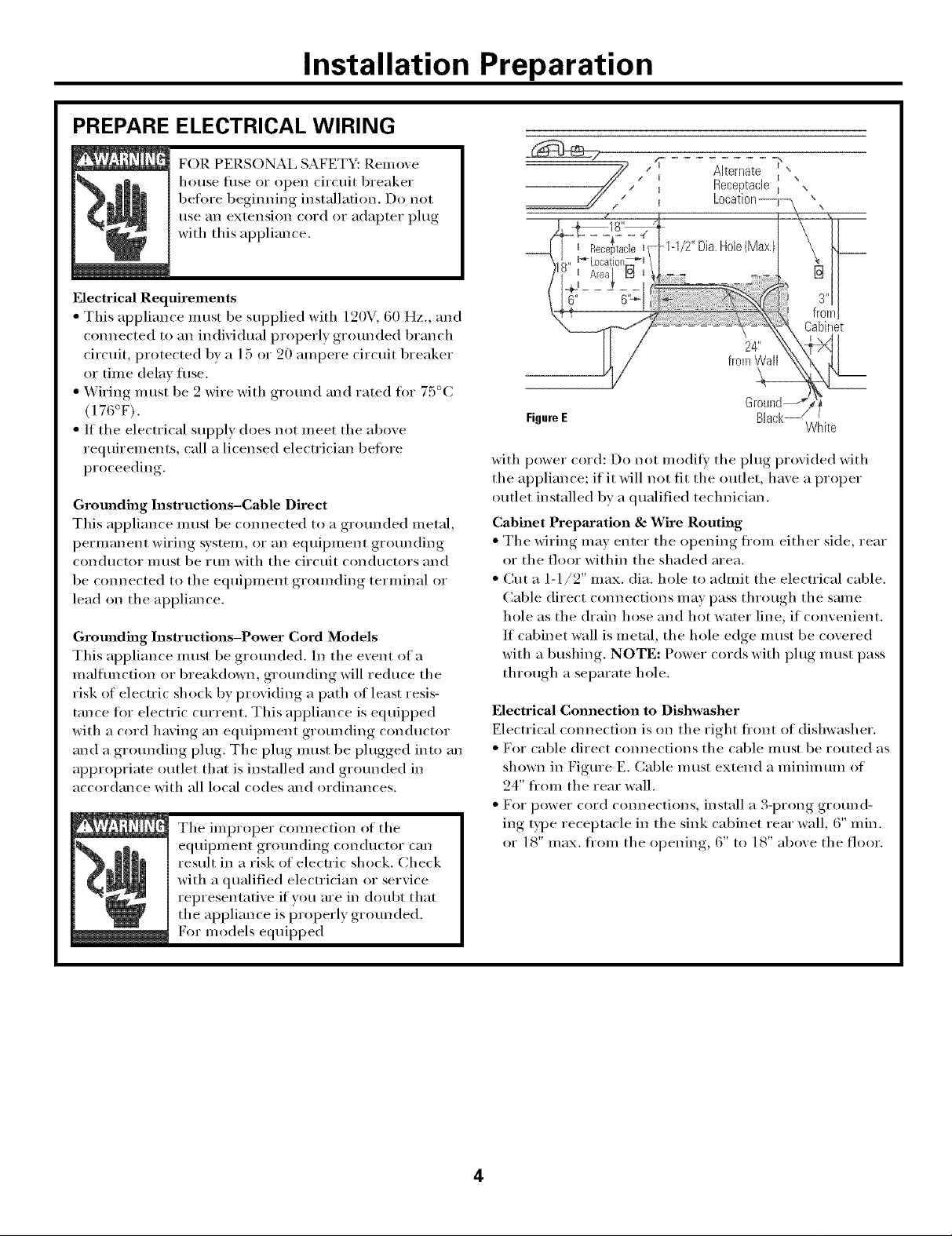
Alternate -_"",
Receptaclet \
FigureE Black
with power cord: Do not modit_' tile plug provided with
tile appliance: if it will not fit tile outlet, have a proper
outlet installed bv a qualified technician.
Cabinet Preparation & Wire Routing
• Tile wiring may enter tile opening fl'om either side, rear
or tile floor within tile shaded area.
• Cut a 1-1/2" max. dia. hole to admit tile electrical cable.
Cable direct com_ections may pass through tile same
hole as tile drain hose and hot water line, if convenient.
If cabinet wall is metal, tile hole edge i,/ust be covered
with a bushing. NOTE: Power cords with plug must pass
through a separate hole.
Electrical Connection to Dishwasher
Electrical com_ection is on the right fi'ont of dishwasher.
• For cable direct comlections the cable must be routed as
shown in Figure E. Cable Inust extelld a minimum of
24" fi'om tile rear wall.
• For power cord comaections, install a 3-prong ground-
ing type receptacle in tile sink cabinet rear wall, 6" rain.
or 18" max. fl'om tile opening, 6" to 18" above tile floor.
! \
Cabinet
White
4