

GE PDT660SSFSS Installation Instructions Manual
Installation
Instructions
Dishwasher
If you have questions, call 1-800-561-3344 or visit our website at: www.GEAppliances.ca
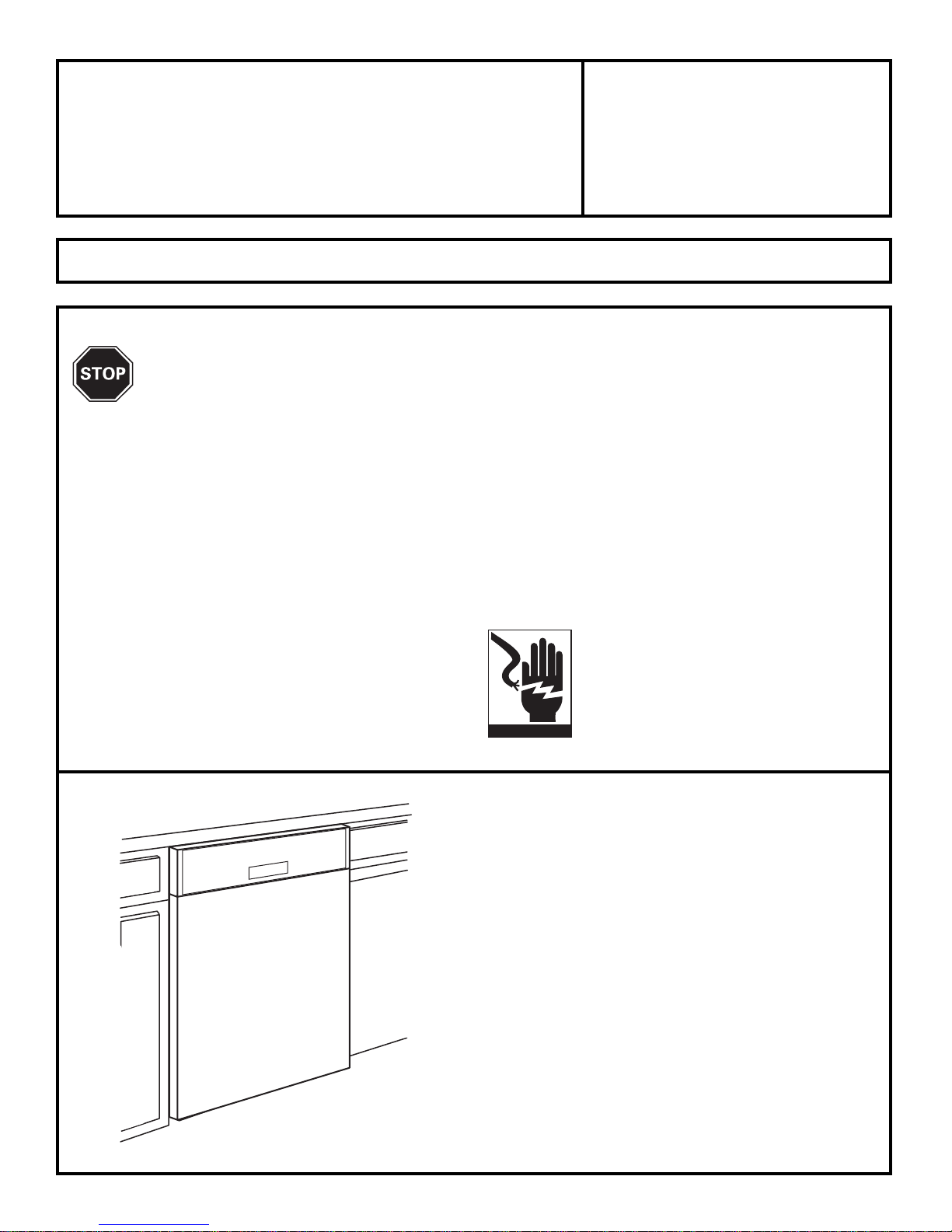
IMPORTANT –
The dishwasher
MUST be installed to allow for future removal from
the enclosure if service is required.
If you received a damaged dishwasher, you should
immediately contact your dealer or builder.
FOR YOUR SAFETY
Read and observe all CAUTIONS and WARNINGS
shown throughout these instructions. While performing
installations described in this booklet, gloves, safety
glasses or goggles should be worn.
BEFORE YOU BEGIN
Read these instructions completely and
carefully.
IMPORTANT
–
Observe all
governing codes and ordinances.
• Note to Installer – Be sure to leave these instructions
for the consumer’s and local inspector’s use.
• Note to Consumer – Keep these instructions with your
Owner’s Manual for future reference.
• Skill Level – Installation of this dishwasher requires
basic mechanical and electrical skills. Proper
installation is the responsibility of the installer.
Product failure due to improper installation is not
covered under the GE Appliance Warranty.
• Completion Time – 1 to 3 Hours. New installations
require more time than replacement installations.
READ CAREFULLY.
KEEP THESE INSTRUCTIONS.
WARNING
To reduce the risk of electrical shock, fire,
or injury to persons, the installer must
ensure that the dishwasher is completely
enclosed at the time of installation.
If you have an installation problem, contact your
dealer or installer. You are responsible for providing
adequateelectrical,exhaustingand otherconnecting
facilities.
La section française commence après la section anglaise
PUB NO.29-5955 7/14 MC
TOOLS YOU WILL NEED:
Phillips head screwdriver
5/16" and 1/4" nutdriver
6" Adjustable wrench
Level
Carpenters square
Measuring tape
Safety glasses
Flashlight
Bucket to catch water when fl ushing the line
Gloves
For New Installations Only:
Tubing cutter
Drill and appropriate bits
Hole saw set
Phillips
Head
Screwdriver
Installation Preparation
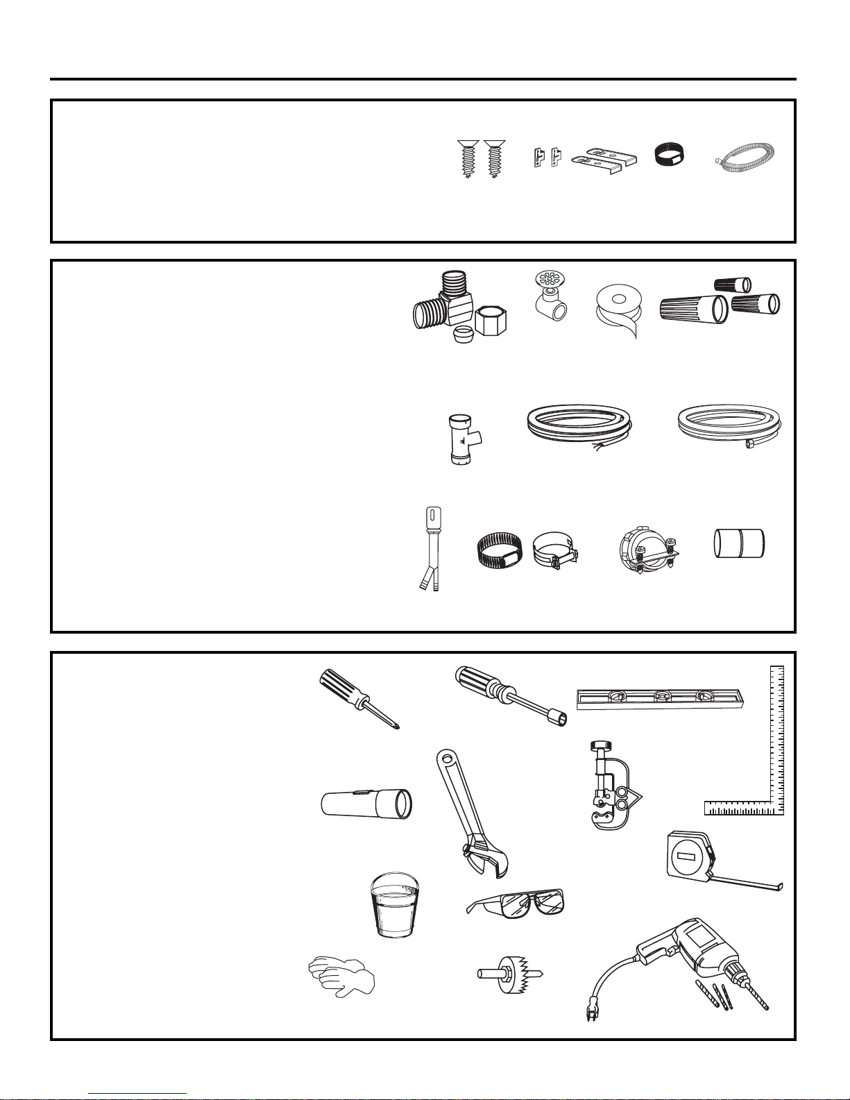
PARTS SUPPLIED:
Four flat head wood screws
dishwasher to underside of countertop
(in literature package).
MATERIALS YOU WILL NEED :
Ferrule, compression nut and 90° Elbow (3/8"NPT external
thread on one end, opposite end sized to fi t water supply)
Thread seal tape
UL Listed wire nuts (3)
Materials For New Installations Only:
Air gap for drain hose, if required
Waste tee for house plumbing, if applicable
Electrical cable or power cord, if applicable
Screw type hose clamps
Strain relief for electrical connection.
Hand shut-off valve
Water line 3/8" min. copper
Coupler for extending drain line, if applicable
90° Elbow,
Ferrule and
Compression Nut
Wire Nuts (3)
Waste Tee
Electrical Cable
(or Power Cord, if applicable)
Hot Water line
Screw Type
Hose Clamps
Coupler
Hand
Shut-Off
Valve
Hole Saw Set
Measuring Tape
Tubing Cutter
Drill and Bits
1/4"
and 5/16" Nutdriver
Safety Glasses
6" Adjustable
Wrench
Bucket
Flashlight
Gloves
Carpenters
Square
Level
2
Thread
Seal Tape
Air Gap
Strain Relief
2 Side
Mounting Clips
2 Top
Mounting Clips
Screw Type
Hose Clamp
Screw type hose clamps and one drain hose.
Drain Hose
to secure
4 Wood Screws
@2 side mounting clips.
2 top mounting cl\ips.
3
Installation Preparation
DRAIN REQUIREMENTS
• Follow local codes and ordinances.
• Do not exceed 10 feet distance to drain.
• Do not connect drain lines from other devices
to the dishwasher drain hose.
• Dishwasher must be connected to waste line with an
air gap (not supplied) or 32" minimum high drain loop,
depending on local codes and ordinances to prevent
back fl ow into the dishwasher.
• Air gap must be used if waste tee or disposer connection
is less than 18" above the fl oor to prevent siphoning.
DRAIN PREPARATION
The type of drain installation depends on answers to
the following questions:
Do local codes or ordinances require an air gap?
Will waste tee or disposer connection be less than
18" above the fl oor?
Will installation have a drain loop less than 32"
above fl oor?
If the answer to ANY of the 3 questions above is YES,
Method 1 MUST be used. Otherwise either Method 1
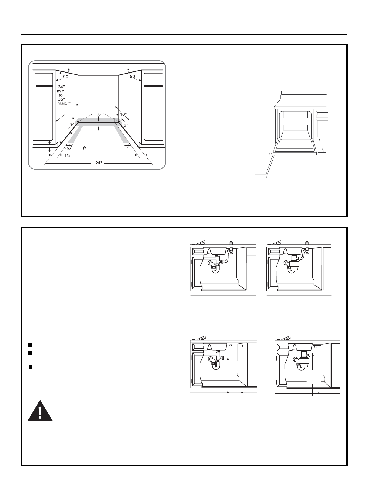
or Method 2 may be used. Figure C or Figure D.
CAUTION:
An air gap MUST BE USED if the drain hose is connected
to waste tee or disposer lower than 18" above the fl oor.
Failure to provide the proper drain connection height
with air gap or 32" minimum, high drain loop will result in
improper draining of the dishwasher.
Install waste tee or disposer and air gap according to
manufacturer’s instructions.
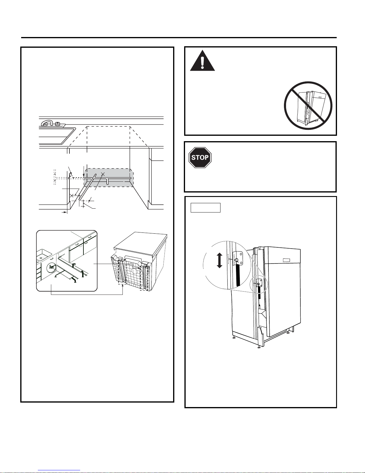
CABINET PREPARATION
• Drill a 1-1/2" dia. hole in the cabinet wall within the
shaded areas shown in Figure A for the drain hose
connection. The hole should be smooth with no sharp
edges.
Method 1 – Air Gap with Waste Tee or Disposer
Method 2 – High Drain with Waste Tee or Disposer
Provide a method to attach drain hose to underside of
countertop.
18"
Min.
32"
Min.
32"
Min.
18"
Min.
Clearance for Door
Opening 2" Minimum
Countertop
Dishwasher
25-5/8"
• The dishwasher must be installed so that drain hose is
no more than 10 feet in length for proper drainage.
• The dishwasher must be fully enclosed on the top,
sides and back, and must not support any part of the
enclosure.
CLEARANCES: When
installed into a corner,
allow 2" min. clearance
between dishwasher and
adjacent cabinet, wall or
other appliances. Allow
25-5/8" min. clearance
from the front of the dishwasher for door opening.
Figure B
•
The rough cabinet opening must be at least 24" deep.
The opening should be 35" max. height.
4
Installation Preparation
Cabinet Preparation & Wire Routing
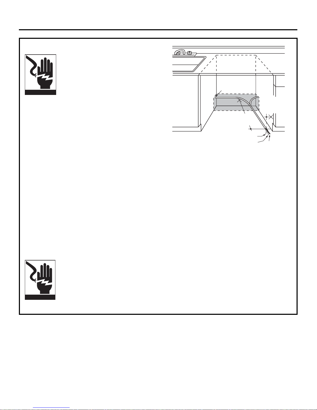
• The wiring may enter the opening from either side,
rear or the fl oor within the shaded area.
• Cut a 1-1/2" max. dia. hole to admit the electrical cable.
The hole must be free of sharp edges. If the cabinet
wall is metal, the hole edge must be covered with a
bushing.
• Cable direct connections may pass through the same
hole as the drain hose and hot water line, if convenient.
If cabinet wall is metal, the hole edge must be covered
with a bushing. NOTE: Power cords with plug must
pass through a separate hole.
Electrical Connection to Dishwasher
Electrical connection is on the right front of dishwasher.
• For cable direct connections the cable must be routed
as shown in Figure E. Cable must extend a minimum of
24" from the rear wall.
• For power cord connections, install a 3-prong grounding
type receptacle. The power-supply receptacle for the
appliance shall be installed in a cabinet or on a wall
adjacent to the undercounter space in which the
appliance is to be installed.
WARNING
FOR PERSONAL SAFETY: Remove house
fuse or open circuit breaker before
beginning installation. Do not use an
extension cord or adapter plug with this
appliance.
PREPARE ELECTRICAL WIRING
Electrical Requirements
• This appliance must be supplied with 120V, 60 Hz., and
connected to an individual properly grounded branch
circuit, protected by a 15 or 20 ampere circuit breaker
or time delay fuse.
• Wiring must be 2 wire with ground.
• If the electrical supply does not meet the above
requirements, call a licensed electrician before
proceeding.
Grounding Instructions – Cable Direct
This appliance must be connected to a grounded metal,
permanent wiring system, or an equipment grounding
conductor must be run with the circuit conductors and
be connected to the equipment grounding terminal or
lead on the appliance.
Grounding Instructions – Power Cord Models
This appliance must be grounded. In the event of a malfunction or breakdown, grounding will reduce the risk of
electrical shock by providing a path of least resistance
for electric current. The plug must be plugged into an
appropriate outlet that is installed
and grounded in accordance with local codes and
ordinances.
WARNING
The improper connection of the
equipment grounding conductor can
result in a risk of electric shock. Check
with a qualifi ed electrician or service
representative if you are in doubt that
the appliance is properly grounded.
White
24"
from Wall
from
Cabinet
Ground
Black
1-1/2" Dia.
Hole (Max.)
2½~3½ in.
(65 ~ 90mm)
5
Installation Instructions
PREPARE HOT WATER LINE
• The line may enter from either side, rear or fl oor
within the shaded area shown in Figure F.
• The line may pass through the same hole as the
electrical cable and drain hose. Or, cut an additional
1-1/2" dia. hole to accommodate the water line.
If power cord with plug is used, water line must not
pass through power cord hole.
Water Line Connection
• Turn off the water supply.
• Install a hand shut-off valve in an accessible location,
such as under the sink. (Optional, but strongly
recommended and may be required by local codes.)
• Water connection is on the left side of the dishwasher.
Install the hot water inlet line, using no less than 3/8"
O.D. copper tubing. Route the line as shown in Figure F
and extend forward at least 18" from rear wall.
• Adjust water heater for 120°F to 150°F temperature.
• Flush water line to clean out debris.
• The hot water supply line pressure must be 20-120 PSI.
CAUTION:
Opening the door will cause the dishwasher
to tip forward. Do not open the door until you are ready
to install the dishwasher. If it is
necessary to open the door, hold
the top of the dishwasher securely
with one hand and hold the door
with the other hand.
• Open the door slowly, if the door drops when
released, increase spring tension. If the door closes
when released, decrease tension.
• Adjust both door springs to the same tension.
• Continue moving the spring pin until door is balanced.
STEP 1 CHECK DOOR BALANCE
To check the door balance, hold the top of the dishwasher fi rmly.
BEFORE YOU BEGIN
Locate and set aside the package containing
2 Phillips head countertop mounting screws
and 2 additional toekick screws (located in
the literature package).
Cabinet Face
Shut-off
Valve
3" From Floor
18" From Wall
From
Cabinet
1-1/2" Dia.
Hole
Hot
Increase
Decrease
5¹⁄
3
~7¹⁄3 in.
(135 ~ 185mm)
Water supply
line
Power cable
5¹⁄3
~7¹⁄3 in.
(135 ~ 185mm)
2½~3½ in.
(65 ~ 90mm)
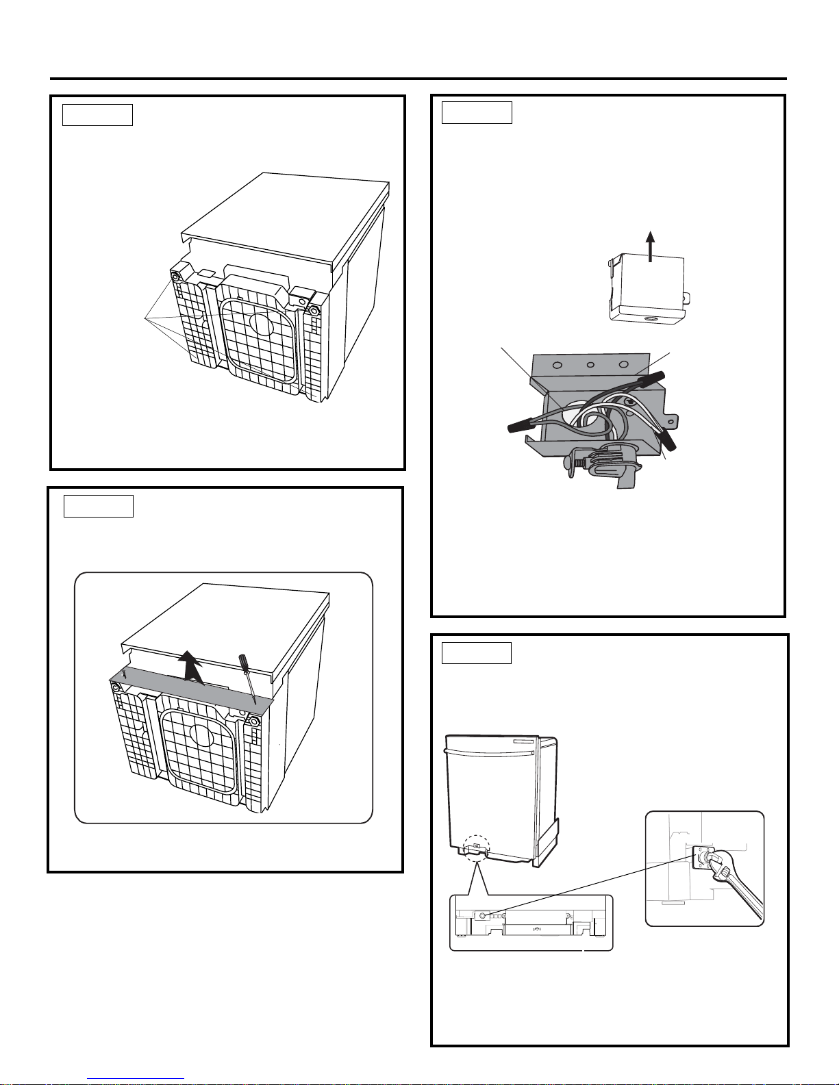
6
Remove
Junction Box
Cover
Installation Instructions
• Do not over tighten 90° elbow, water valve bracket
could bend or water valve fitting could break.
• Position the end of the elbow to face the bottom
dishwasher.
STEP 5 INSTALL 90° ELBOW
• Wrap 90° elbow with thread seal tape. Do not use
plumber's putty.
• Install a 90° elbow onto the water valve.
STEP 3 REMOVE TOEKICK
• Remove the 2 toekick screws. Lift off the piece
toekick.
• Measure installation height and dishwasher height.
Extend leveling legs out from the dishwasher base,
1/4" less than installation height.
STEP 2 ADJUST LEVELING LEGS
• Move the dishwasher close to the installation location and lay it on its back.
STEP 4 INSTALL POWER CORD
Skipthis step if dishwasher willbe direct wired. Use
power cord kitWX09X70910 available for purchase from
an authorized GE ealer. The power cord and
connections must comply with
local codesand
ordinances.
• Recommended power cord length is 54" min. and
64" max.
Adjust
Installation
Height
• Connect incoming
power cord white (or ribbed)
to dishwasher white, black
(or smooth) to black and ground to dishwasher green
wire. Use UL listed wire nuts of appropriate size.
• Replace junction box cover. Be sure wires are not
pinched under the cover.
Green wire to Green wire ( Ground)
Black wire to Black wire ( Hot)
White wire to White wire ( Neutral)
parts d
cUL/
of the
right
1
7
Power Cord
(If Used)
Insulation
Blanket
Water
Line
House
Wiring
Drain
Hose
Maximum
Drain Hose
Length 10'
Installation Instructions
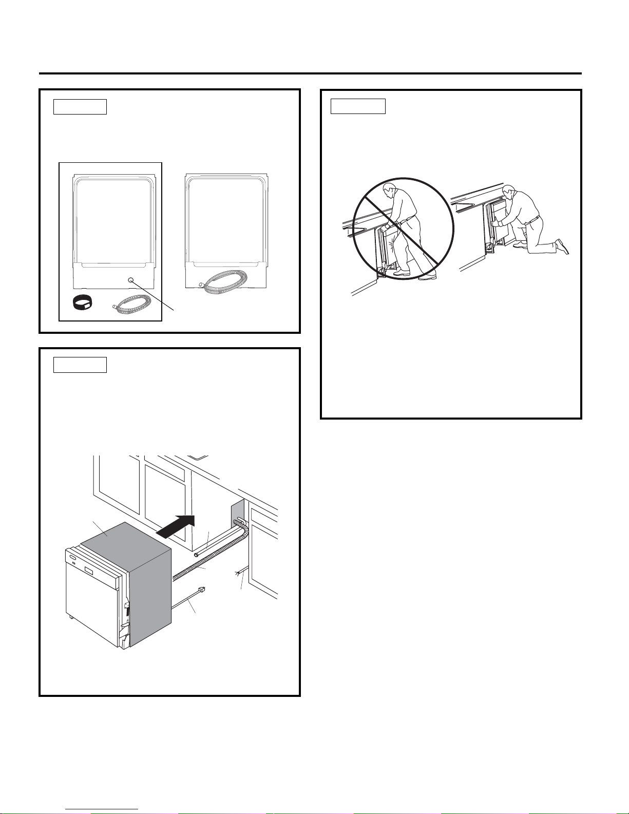
STEP 8 SLIDE DISHWASHER
PARTIALLY INTO CABINET
DO NOT PUSH AGAINST FRONT PANEL WITH KNEES.
DAMAGE WILL OCCUR.
• Slide dishwasher into the opening a few inches at a time.
• As you proceed, pull the drain hose through the
opening under the sink. Stop pushing when the dishwasher is a few inches forward of adjacent cabinetry.
• Make sure drain hose is not kinked under the dishwasher and there is no interference with the water
line and wiring or any other component.
TIP: Position water line and house wiring on the fl oor
to avoid interference with base of dishwasher.
STEP 7 INSERT DRAIN HOSE
THROUGH CABINET
• Upright the dishwasher and position in front of the
opening. Insert drain hose into cabinet wall hole.
If a power cord is used, guide the end through a
separate hole.
STEP 6 INSTALL DRAIN HOSE
• Install the screw type hose clamps to the drain hose.
hose, then tighten the screw type hose hose.
Do Not Push Against
Front Door Panel With
Knee. Damage to The
Door Panel Will Occur.
The drain hose installation hole
• Install the drain hose to the drain hose installation
Installation Instructions
8
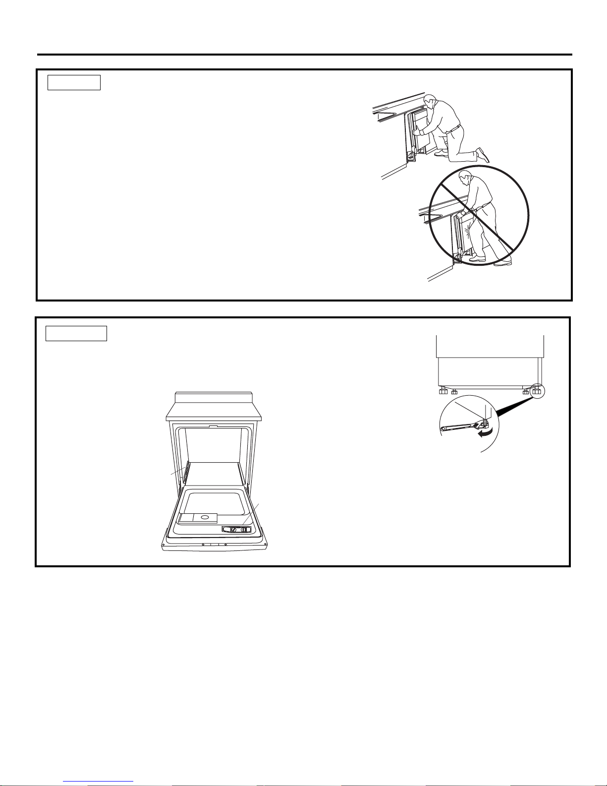
STEP 9 POSITION DISHWASHER UNDER COUNTERTOP
• Check to be sure that wires are secure under the
dishwasher and not pinched or in contact with door
springs or other dishwasher components.
TIP: Check tub insulation blanket, if equipped. It should
be positioned so it is not bunched up or interfering with
door springs. Check by opening and closing the door.
• Push dishwasher into cabinet. The front corners of the
dishwasher door should be fl ush with cabinet doors.
Be careful not to dent font panel with knees or damage countertop or cabinets with dishwasher parts.
Do Not Push Against
Front Door Panel With
Knee. Damage to The
Door Panel Will Occur.
Reposition Dishwasher
by Grasping Both
Sides With Hands
STEP 10 LEVEL DISHWASHER
Dishwasher must
–
IMPORTANT
be level for proper dish rack operation and wash performance.
• Place level on
door and rack
track inside the
tub as shown to
check that the
dishwasher is
level.
Check
Level
Front
to Back
Check
Level
Side
To Side
• Level the dishwasher
by adjusting the four
leveling legs individually.
Turn Legs
to Adjust
TIP: Pull lower rack out, about halfway. Check to
be sure the rack does not roll forward or back into
dishwasher. If the rack rolls in either direction, the dishwasher must be leveled again.
• If door hits the tub, the dishwasher is not installed
correctly. Adjust leveling legs to align door to tub.
 Loading...