

GE PFSS5PJXCSS, PFSS5PJXBSS, PFSS5PJXASS, PFSS5NJXCSS, PFSS5NJXBSS Owner’s Manual
...
0
ge.com
Safety Instructions ........... 9 3
Operating Instructions
Additional Features ............. 8
Automatic Icemaker ............ 11
Care and Cleaning .......... 19-13
Controls ..................... 4-5
Crispers and Pans ............... 9
Freezer ....................... 10
Repl acing the i _igh t Bulbs ....... 14
Shelves and Bins .............. 7, 8
_'ater Dispenser . .............. 11
Water Filmr .................... 6
Models21 and25
Cong_lateur inf&ieur
R frig rateurs
Installation Instructions
Installing the Anti-Tip
Floor Bracket ............... 18-19
Installing the Refrigerator .... 20-24
Installing the ¼'ater Line ..... 33-35
Preparing m Install
the Refligerator . .............. 17
Removing and Replacing the
Freezer Drawer . ............ 95, 26
Reversing the Door Swing
(Single Door Refligerator
Models only) ............... 97-29
Removing and Replacing
the Doors (Double Door
ReDigerator Models only) .... 30-39
Trim Kits and Decorator Panels..15-16
Troubleshooting Tips ....... 36-40
Normal Operating Sounds ....... 36
Consumer Support
Consumer Support ..... Back Cover
Performance Data Sheet ........ 47
Product Registration
for Canadian Customers ..... 43, 44
Product Registration
for U.S. Customers .......... 41,49
State of California ¼'ater
Treatment Device Certificate ..... 48
_'arranty fox Canadian
Customers .................... 46
VVarranty fox U.S. Customers ..... 45
Writethemodelandserial
numbershere:
La section fran_aise commence a la page 49
Congelador inferior
Refrigeradores
La secci6n en espa#ol empieza en /a pagina 93
Model #
Serial #
Find these numbex_ on a label
on the right side, near the top of
the refrigerator compartment.
200D9366PO02 49-60530-2 01-08Jfl

IMPORTANTSAFETYINFORMATION.
READALLINSTRUCTIONSBEFOREUSING.
WARNING!
Use this appliance only for its intended purpose as described in this Owner's Manual.
SAFETYPRECAUTIONS
When using electrical appliances, basic safety precautions should be followed, including the following:
_:i:This reflJgerator must be properl_ installed
and located in accordance with the Installation
Instructions before it is used.
i)::Do not allow children to climb, stand or hang
on the shelves in the refl'igeratm: They could
damage the refi_igerator and seriously iqjm'e
themselves.
::_Do not touch the cold sm'fi_ces in the fl'eezer
compartment when hands are damp or wet.
Skin mm stick to these extremely cold stmfi_ces.
i?<Do not store or use gasoline or other flammable
wq)(ns and liquids in the vicinity of this or any
other appliance.
i)::Keep finge_s out ot the "pinch point" areas;
clearances between the do(ns and between
the doo_s and cabinet are necessarily small.
Be careful closing dom5 when children are
in the area.
i(i'In refl_igeratms Mth automatic icemakeis,
avoid contact with the moving parts (ff the
ejector mechanism, or with the heating element
that releases the cubes. Do not place finge_s or
hands on the automatic icemaking mechanism
while the refl_igerator is plugged in.
i!:i'UnI_lug the refl-igerator before cleaning and
making repai_.
NOTE: Westronglyrecommendthat any servicingbe
performedbyaquafified individual.
i!:;Setting either or both controls to 0 (Off)does
not remove power to the light circuit.
_::_Do not i'eti'eeze fFozen foods which have
thawed complemly.
DANGER!RISKOFCHILDENTRAPMENT
PROPERDISPOSALOFTHEREFRIGERATOR
Refrigerants
of the i)ast.Jtmked or abandoned reffigerato_ are
Child entrapment and suffocation are not problems
still dangerous...exert if they will sit fin" 'ijust a few
dins." If _ou are getting dd of yore" old refl%erat(m
please t011ow the instructions below to help prevent
accidents.
Before YouThrewAway YourOld Refrigerator
All refl_igeration products contain refl'igerants,
which under fe(leral law must be removed prior
to product disl)osal. If you are getting rid of
an old refi'igeration product, check with the
company handling the disposal about what
to do.
or Freezer:
iJi::_ke off the dome.
iJi::i,eaxe the shelves in place so that children may
not easiE climb inside.
USEOFEXTENSIONCORDS
Because of potential safety hazards under certain conditions, we strongly recommend against
the use of an extension cord.
However; if you must use an extension cord, it is absolutelx necessary that it be a UiTlisted (in the United
States) or a CSA certified (in Canada),. -_are ,gr°tmding, t_,])e appliance extension cord having a grotmding
2
t)])e I)lu(*_and outlet and that the electrical rating of the cord be 15 amperes (minimum) and 120 xolts.
a, WARNING!
HOWTOCONNECTELECTRICITY
Donot, under anv circumstances, cut or remove the third (ground) prong from the power cord.
For personal safe_ this appliance must be properly grounded.
ge.com
The power cord of this appliance is equipped
with a 3-prong (gromMing) plug which mates
with a standard B-prong (gromMing) wall outlet to
minimize the possibili_, of electric shock hazard
fi'om this appliance.
Have the wall outlet and circuit checked by a
qualified electrMan to make sm'e the out.let is
properly gromMed.
Where a standard 2-prong wall outlet is
encom_tered, it is yore" personal responsibili_' and
obligation to have it replaced with a properly
gromMed B-prong wall outlet.
The refi_igerator should always be plugged into its
own individual electrical outlet which has a voltage
rating that matches the rating plate.
This provides the best pe_tkmnance and also
I)rexents oxerloading, house wiring circuits which
couM cause a fire hazard from oxerheated wires.
Never m_plug yore" refrigerator by pulling on the
power cord. Mways grip plug firefly and pull
straight out ti'oln the outlet.
Repair or replace immediately all po_vr cords that
have become fl'ayed or otherwise damaged. Do not
use a cord that shows cracks or abrasion damage
along its length or at either end.
\4]_en moving the refrigerator away fl'om the
wall, be careflfl not to roll over or damage the
power cord.
READANDFOLLOWTHISSAFETYINFORMATIONCAREFULLY.
SAVETHESEINSTRUCTIONS
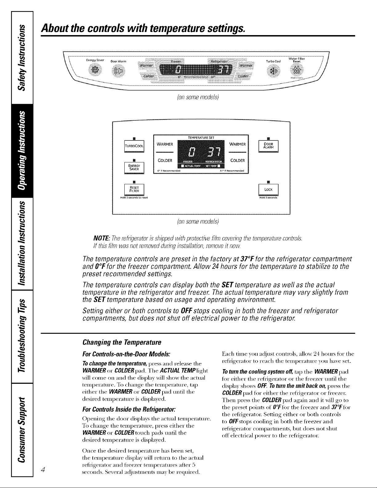
Aboutthe controlswith temperaturesettings.
(onsomemodels)
[]
[]
[] []
Hold 3 seconds to _set NoEd 3 seconds
WARMER _ _WARMER
COLDER COLDER
oo F Recommended 37_F Recommended
TEMPERATURE SET
[]
(onsomemodels)
NOTE: Therefrigeratoris shippedwith protective film coveringthe temperaturecontrols.
If this film wasnot removedduringinstallation, removeit now
Thetemperature controls are preset in the factory at 37°F for the refrigerator compartment
and O°Ffor the freezer compartment. Allow 24 hours for the temperature to stabilize to the
preset recommended settings.
Thetemperature controls can display both the SET temperature as well as the actual
temperature in the refrigerator and freezer. The actual temperature may vary slightly from
the SETtemperature based on usage and operating environment.
Setting either or both controls to OFFstops cooling in both the freezer and refrigerator
compartments, but does not shut off electrical power to the refrigerator.
Changingthe Temperature
For Controls-on-the-DoorModels:
To change the temperature, press and release the
WARMER or COLDER pad. The ACTUAL TEMPlight
will come (m and the display will show the actual
temi)eramre. To change the temperature, tap
either the WARMERor COLDERpad until the
desired temperature is displayed.
For ControlsInside the Refrigerator:
Opening the door displa):s the actual temi_eramre.
To change the temi)eramre, press either the
WARMER or COLDER touch pads until the
desired temperature is displayed.
Once the desired temperature has been set,
the temperatm'e display will return to the actual
4
refi-Jgei'ator and fl'eezer temperattlres afiei" 5
seconds. Several ac!iusmlents may be required.
Each time )ou ac!iust controls, allow 24 horns fi_r the
refrigerator to reach the temperature you ha_e set.
To turn the coolingsystem off, trip the WARMER pad
fro"either the refligerator or the fl'eezer until the
display shows OFF. To turn the unit back on, press tile
COLDER pad for either the refligerator or fl'eezei:
Then press the COLDER pad again and it will go to
the preset points of O°Ffi)rthe fl'eezer and 37°Ffi)r
the refiigeratoi; Setting either or both controls
to OFFstops cooling ill both the fl'eezer and
refligerator conq)artments, but does not shut
off electrical power to the refl_igeratoi:
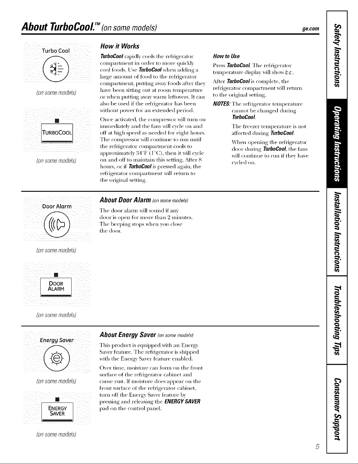
About TurboCooEM(on some models) ge.oom
How it Works
How to Use
Press TurboCool.Tile retiigerator
temperatm'e display will show ccc.
_Mter Turbogoolis complete, tile
refligerator compartment will return
to tile original setting.
NOTES:Tile refligerator temperatm'e
cmmot be changed dining
TurboCoot
Tile fl'eezer temperature is not
affected during TurboCoot
_4]/en opening the refrigerator
door (lining TurboCool,tile liras
will continue to mn if they have
cycled on.
(onsomemodels)
'onsome models)
TurboCoolrapidly cools tile reliigerator
colnl)artinexlt ixl order to inore quickly
cool fi)ods, Use TurboCool when adding a
large amount of toed to the refligerator
compartment, putting away fi)o(ls after they
have been sitting out at rooln temperature
or when putting away waml leftovers. It can
also be used if the retiigerator has been
without power for an extended period.
Once acti\:_md, the compressor will turn oil
immediateh and tile rims will Q'cle on and
off at high speed as needed for eight hom_.
The compressor will continue to mn tmtil
tile refl_igerator compartment cools to
approximately 34°F (l °C), then it will cycle
on and off to maintain this setting. _Mter 8
hom_, or if TurboCoolis pressed again, tile
refl_igerator compa rtm ent will return to
the original setting,
o0or Alarm
(onsomemodels)
_ ii _ i I i i ii_ i
(. A,A.,D°oRli ¸
iiiii iii _ii
(onsomemodels)
(onsomemodels)
About Door Alarm (onsomemodels)
Tile door alaml will so/md if am'
door is open ti)r more than 2 minutes.
The beeping stops when you close
tile door,
About Energy Saver (onsomemodels)
This product is equiI)ped with an Energy'
Saver feattlre. Tile refl_igerator is shil)ped
with tile Energy' Saver teatm'e enabled.
Over time, moisture can tOml on tile fl'ont
surli_ce of tile refl_igerator cabinet and
cause rust. If moistm'e does appear on tile
fl'ont surfi_ce of tile refligerator cabinet,
mrn off tile Energy Saver teatm'e by
pressing and releasing the ENERGY SAI/ER
pad on tile control panel.
(onsomemodels)

Aboutthe water filter.(onsomemodels)
Water Filter Cartridge
The water filter cartridge is h)cated in the
back upper right corner of the refi-igerator
coiilpa i'tlllent,
When to Replace the Filter
There is a replacement indicator
light fi)r the water filter cartridge on the
temperatm'e display. This light will turn
orange to tell you that you need to replace
the filter soon. The filter cartridge should
be replaced when the replacement
indicator light turns red or if the flow
of water to the dispenser or icemaker
decreases.
Installing the Filter Cartridge
O If you are replacing the cartridge,
fi_t remove the old one. Open the
cam-idge cover by pressing in on the
tab at the fl'ont and pulling down.
O Remoxe tile cartridge b) sh)wly rotating
it c()tmterch)ckwise. A small amomlt of
water may drip down.
Filter Bypass Plug
_)u must use the filter b)pass plug when a
replacement filter cartridge is not available.
The icemaker will not operate without the
filter or filter bypass plug.
Replacement Filters:
To order additional filter cartridges
in the United States, visit our Webs#e,
ge.com, or call GE Parts and Accessories,
800.626.2002.
Filter Model (;SWF
Customers in Canada should consult
tile velh)w pages fi)r the nearest Mabe
Serxice Center:
Water Fitter
Reset
Hold 3 Secs
(on some models)
RESET]
Hold 3seconds to reset
(on some models)
A CAUTION:/fa,>hasbeentra ed
in thesystem,thefiltercartridgemaybeejectedas
it isremovecLUsecautionwhenremoving.
0 Rem°_'e the protecti',e fi)il from the
end of the cartridge.
lining up the arr,:)w on the cartridge
and tile cartridge holder; slowly rotate
the cartridge clockwise tmtil it stops.
_A]mn the cartridge is properly
installed, you will teel it "click" as it
locks into place. The grip on the end
of the cartridge should be positioned
vertically. Do not overtighten,
O Close the cartridge cove_:
O Rtm water fl'om the dispenser fl)r
3 minutes (about 1 i/_)galhms) to clear
the system and prevent sputtering.
See To Use the Oispenser section.
Press and hold the RESETWATERFILTER
pad fi)r 3 seconds.
NOTE: A newEqnstalled water filter cartridge
may cause water to spurt fl'om the dispense_:

Aboutthe shelvesandbins. gecem
Not all features are on all models.
Rearranging the Shelves
Shel;es in the refl_igerator comi)artn_ent are a(!iustable.
Refrigerator Compartment
To remove:
0 Remo_e all items fl'om the shelf.
0 Tilt the shelf up at the fl'ont.
0 I,ifl the shelf up at the back and
Some models have wire shelves that
can be adjusted in the same mamTer.
b_l"ng the shelf out.
To replace:
0 _qfile tilting the shelf up, insert the top
hook at the back of the shelf in a slot
on the track,
0 I,ower the fl'ont of the shelf tmtil the
bottom of the shelf locks into place,
Spillproof Shelves (onsomemodels)
Spillproof shelves have special edges to
help prevent spills fl'om dripping to lower
shelves, To remove or replace the shelves,
see Rearranging the Shelves,
Slide-Out Spillproof Sheff (onsomemodels)
The slide-out spillprooI shelf allows you
to reach items stored behind othe_, The
spedal edges are designed to help prevent
spills fl'om dripping to lower shelves.
Toremove:
0 Remove all items ti'om shel£
0 Slide the shelf ()tit tlntil it stops.
lift the fl'ont edge of the shelf tmtil the
central tabs are above the fl'ont bin:
0 (_ontinue pulling the shelf torward
tmtil it can be removed.
Toreplace:
0 Place the rear shelf tabs just in fl'ont of
the central notches on the shelf fl'ame,
Slkle the shelf in tmfil the central tabs
are slightly behind the fl'ont ba_;
0 i,ower the shelf into place tmfil it is
horizontal and slide the shelf in.
Makesurethattheshelfsitsfiatafterre/bsta//atlbn
anddoem'tmovefree/;/fromsidetoside.
Makesureyoupushtheshe/yesa//thewayin
beforeyoudosethedoor
7
Aboutthe shelvesandbins.
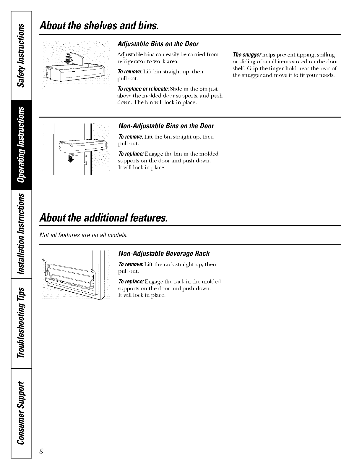
Adjustable Bins on the Door
Ac!iustable bins can easily be carried ti'()m
i'eti]gei'_ltoi" 1o w()x'k _lI'e_l,
To remove: I,ifi bin straight ui), then
pull out.
To replace or relocate: Slide in the bin j ust
above the molded door supports, and push
down, The bin will lock in place,
Non-Adjustable Bins on the Door
To remove: Lift the bin straight u[), then
pull out.
To replace:Engage the bin in the molded
SUl)ports on the door and push down.
It will lock in place.
Aboutthe additional features.
The snuggerhelps prevent tipping, spilling
or sliding of small items stored on the door
shelf. (h_iI) the finger hold near the rear of
the snugger and move it to fit w)ur needs.
Not all features are on all models,
Non-Adjustable Beverage Rack
To remove: Lift the rack straight up, then
ptfll out.
To replace:Engage the rack in the molded
iI_iii!_i_iii_i_ ii
SUl)l)OrtS on the door and push down.
It will lock in place.
8
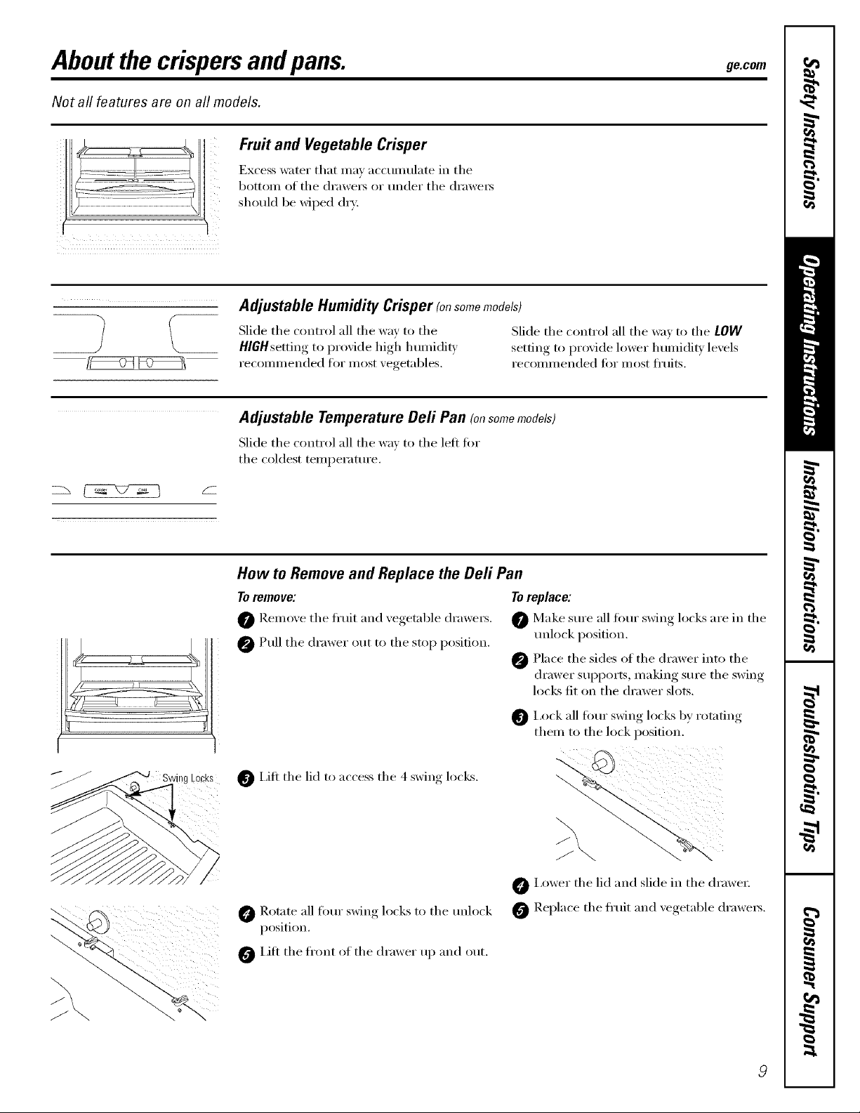
Aboutthe crispersandpans. gecem
Not all features are on all models.
Fruit and Vegetable Crisper
Excess water that ma_ acctmmlate in the
bottom of the (h'awe_ or under the (h'awe_
j [
should be wiped (lr_;
Adjustable Humidity Crisper (onsomemodels)
Slide the control all the way to the Slide the control all the wax to the LOW
HIGHsetting to proxide high humidit_ ,settino-_to proxide lower humidi_' lmels
recommended for most xegetables, recomm ended fiw most fl'uits.
Adjustable Temperature Deft Pan (onsomemodels)
Slide the control all the wa_ to the left fin,
the coldest temperature.
'lRg LOCKS
How to Remove and Replace the Deft Pan
Toremove:
0 Remoxe the fl'uit and xegetable (h'awei_.
@Pull the drawer ()tit to the stop position.
I,ifl the lid to access the 4 swing locks.
Rotate all fimr ,sxdn,*_locks to the unlock
position.
0 Lift the fl'ont of the drawer up and out.
Toreplace:
Make sure all tour swing locks are in the
unlock position.
@ Place the sides of the drawer into the
drawer supports, making sure the swing
locks fit on the drawer slots.
I,ock all fimr swing locks by rotating
them to the lock position.
0 i,ower the lid and slide in the drawer
Replace the fl'uit and xegetable drawei_.
J
J

Aboutthe freezer.
Not all features are on all models.
Freezer Shelves and Baskets
0 A shelf above the ice storage bin
0 A shallow fllll-width basket
0 A deep fllll-width basket
Appearance and featuresmay vary
Basket Removal
To remove the deep full-width basket on
freezer drawer models:
0 Open the fl'eezer drawer until it stops.
_]b Lift the basket so that all 4 tnbs are {)tit
Appearance may vary
r
Tab
v
A half:width basket
The fl'eezer basket rests on the inside
robs on the drawer slides.
of the slide bracket.
Tilt the basket and lift out of the
(lI'aweI_
When replacing the deep full-width basket
Tilt the basket back and lower it down
into the drawer. Rotnte the basket to a
horizontnl position and press it down into
the 4 aligmnent tabs,
NOTE:_M_z_sbe sure that all 4 basket tnbs
are engaged in the slide brackets befl)re
sliding back into the fl'eezer
Appearance may vary
0 Make sm'e the plastic sleexes remain
attached to the 4 tabs on the slide
brackets,
To remove the half-width basket:
0 Ptfll the basket out to the stop location.
Lift the basket u I) at the fl'ont to release
it fl'om the slides,
0 Lift the back uI) and out of the slide,
Toremove the shallow full-width basket:
Ptfll the basket out to the stop location,
0 Lift the fl'ont uI) and oxer the stop
location,
When replacing the basket, make sure that
the wire tnbs and wire hooks on the sides
ot the basket go into the slots in the top
ot the ui)per basket slides.
NOTE:_Mw'a_:sbe sure to flfllv close this
basket.
0 Lift the basket ul) and out,
Appearance may vary
10
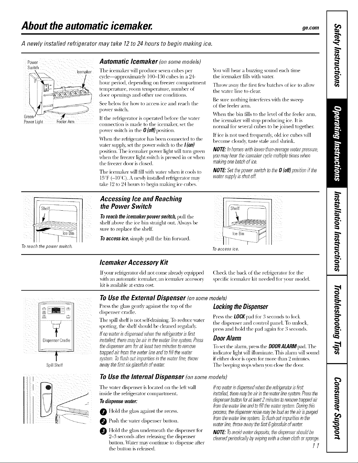
Aboutthe automaticicemaker, ge.com
A newly installed refrigerator may take 12to 24 hours to begin making ice.
Automatic Icemaker (onsomemodels)
Icemaker
Green
PowerLight
Tile icemaker will produce seven cubes per
c}cle--approxinmml) 100--130 cubes in a 24-
]lour peliod, depending on ti'eezer compartment
[el-i-|pel;ittll'e, I'OO1T| tel//pel;Itt/re, ntll-i-|ber of
door openings and other use conditions.
See belo_ for ho_ to access ice and x>ach the
b ¸
po_er switch.
If file retiigemtor is operated betore the _mr
connection is made to tile icemaker, set the
po_er switch in the 0 (off)position.
_Almn the mfiigerau)r has been connecmd to the
_ter supl% _t tile po_r switch to file I(on)
position. Tile icemaker po_r light will mm green
\dmn the fi'eezer light switch is pm,_sed in or \allen
the ti'eezer door is cl(xsed.
The icemaker will fill xqth water when it cools to
lS°F (-I0°C). A needy installed refiigemtor max
rake 12 to 24 houx_ to l_g6n making ice cul_s.
_i)tl will hear a buzzing sound each time
the icemaker fills xdth water.
Tim)w mva_the firsttewbatches of ice to allow
the x_aterli}/eto clear.
Be sure nothing interteres with the sweep
of the teeler ann.
When the bin fillsto tile level of the teeler arm,
the icemaker willstop producing ice. It is
normal tbr several cubes u) bejoined togethex:
If ice is not used fl'equentlBold ice cubes will
become cloud}, taste stale and shrink.
NOTE:Inhomeswithlower-than-averagewaterpressure,
youmayheartheicemakercyclemultipletimeswhen
makingonehatchofice.
NOTE:Setthepowerswitchtothe0(off)positionif the
watersupplyisshutoff.
Toreachthepowerswitch.
i II!IIIII I !
7
DispenserCradle
SpillShelf
Accessing Ice and Reaching
the Power Switch
Toreachtheicemakerpower switch, pull the
shelf aboxe tile ice bin straight out. ,_'_,;1}s be
sure to replace the shelt:
Toaccessice,simply pull the bin fiwward.
> .....->--YI
Toaccess ice.
Icemaker Accessory Kit
Ifyour reIfigemtor dkl not comeaheadyequipped
with an automatic icemake_; an icemaker accessory
kit is a_dlable at extra cost.
To Use the External Dispenser (onsomemodels)
Press file glassgen@ ag_linstthe tot/of file
dispenser cnldle.
The spill shelf isnot self:dnlining.To i_(hmewater
spotting, the shdf should be cleaned x_g-ularl_:
Ifnowaterisdispensedwhentherefrigeratorisfirst
installed,theremaybeairinthewaterlinesystem.Press
thedispenserarmfuratleasttwominutestoremove
trappedairfromthewaterlineandtofillthewater
system.Toflushoutimpuritiesinthewaterfine,throw
awaythefirstsixgbssfulsofwater
Check the back of the reti'igerator tar the
specific icemaker kit needed for your model.
LockingtheDispenser
Press the LOCKpadtar 3 seconds to lock
the dispenser and control panel. To unlock,
press and hold the pad ag'ain tar 3 seconds.
DoorAlarm
Toset the almm, p)_ the DOORALARMIlad.The
in(ficator light will illuminate. This alam-i will sound
ffeither (k)or is open tar rrlol_ than 2 minums.
Tile beeping stops \dmn }ou close the deal:
ToUse the Internal Dispenser (onsomemodels)
The x_ater disi)enser is located on tile left x_dl
inside tile reti'igerator compartment.
Todispensewater:
Hold file <glassag'<dnstfile recess.
O Push the wamr dispenser button.
Hold die glass underneath the disllenser for
2-3 seconds alter _leasing the dispenser
button. Water rriat continue to dispense atier
the button is telex;seal.
finewaterisdispensedwhentherefrigeratorisfirst
installed,theremaybeairinthewaterlinesystem.Pressthe
dispenserbuttonforatleast2minutestoremovetrap_dair
fromthewaterlineandtofillthewatersystem.Duringthis
process,thedispensernoisemaybeloudastheairispurged
fromthewaterlinesystem.Toflushoutimpuritiesinthe
waterline,throwawaythefirst6glassfulsofwater
NOTE:Toavoidwaterdeposits,thedispensershouldbe
cleanedperiodicallybywipingwithacleanclothorsponge.
11

Careand cleaning ofthe refrigerator.
Cleaning the Outside
The doorhandles and trim. Clean with a cloth
daml)ened with soapy water: Dry with a soft
cloth. Do not use wax on the door handles
and trim.
Keep the outside clean. Wipe Mth a clean
cloth lightly dampened Mth kitchen
appliance wax or miM liquid dish
detergent. Dry and polish with a clean,
soft cloth.
Donot w/i)etherefni?eratorwith asoileddish
clothor wettowel. Thesemayleavea residue
that canerodethepaint.Donot usescouring
pads,powderedcleaners,bleachorcleaners
containingbleachbecausetheseproductscan
scratchand weakenthepaintfinish.
Cleaning the Inside
The stainless steel panels and door handles.
Stainless steel (on some models) can be
cleaned with a commerdallv a\_filable
stainless steel cleanex: A si)ra>on stainless
steel cleaner works best.
Do not use appliance wax or polish
on the stainless steel.
Silver-plated plastic parts. Wash parts with
soap or other mild detexgents. _,\]I)e clean
with a sponge, damp cloth or paper towel.
Do not scrub with steel-wool pads or other
abrasive cleaners.
Tohelp prevent odors,leave an (>pen b(:,x (:,t
baking soda in the reti_gerator and ti'eezer
COIlll)}l rtll/e nts.
Unplug the refrigerator before cleaning. If this
is not practical, wring excess moisture out
of sponge or cloth when cleaning arotmd
switches, lights or controls.
Use an appliance wax polish on the inside
surti_ce between the (loo_.
Use warm water and baking soda solution--
about a tablespoon (15 ml) of baking soda
to a quart (l liter) ot water: This both cleans
and neutralizes odo_. Rinse and wipe dry.
J_dter cleaning the door gaskets, appl,v a
thin laver of petroleum jelly to the door
gaskets at the hinge side. This helps kee I)
the gaskets fl'om sticking and bending out
ot shape.
Avoid cleaning co/c/glass shelves with hot water
because the extreme temperature difference may
cause them to brea£ Handle glass she/yes
carefuflg Bumping tempered glass can cause
it to shatte_
Donot washanypiasticrefngeratorpartsin
thedishwashen
Silver-accented plastic parts. X,_hsh parts
with soapy watex: V(ipe clean with a sponge,
damp cloth or paper towel.
Do not scrub with steel-wool pads or other
abrasive cleane_.
12

Behind the Refrigerator
Be careful when moving tile refl_Jgerator
away fl'om tile wall. _M1t,/pes of floor
coverings can be damaged, pa_licularly
cushioned coverings and those with
embossed S/li_lces,
Raise tile leveling legs located at tile
bottom fl'ont ot tile refrigerator.
Pull tile refl_Jgerator straight out and return
it to position by pushing it straight in.
Preparing for Vacation
g_com
Moving tile refl_Jgerator in a side direction
may result in damage to the floor covering
or refrigerator.
I,ower the leveling legs tmtil thev touch
tile floo_:
When pushing the refrigerator back, make sure
you don't roll over the power cord or icemaker
supply fine (onsome models) and ensure the
anti-tli9 bracket is engaged (if equligped).
For long \;l(-ations oi" absen(-es_ i'eil/ove
food and Unl)lug tile refl_Jgei'atoi: Clean tile
interior with a baking soda solution of one
tablespoon (15 ml) of baking soda to one
quart (1 liter) of water: i,eave the doo_
open.
Set tile icemaker power switch to tile 0 (off)
position and shut off tile water supply to
the refl_Jgeratm:
Preparing to Move
Secure all loose items such as base grille,
shelves and drawe_ by taping them
securely in place to prevent damage.
\_]/en using a hand truck to move tile
refl_Jgeratot; do not rest tile fl'ont or back
ot the refl_Jgerator against the hand truck.
This could damage the refl_Jgerato_: Handle
only fl'om tile sides of tile refl_igeratm:
If tile temperature can drop below
fl'eezing, have a qualified servicer drain the
water supl)ly system (on some models) to
prevent serious property damage due to
flooding.
Besuretherefngeratorstaysin anupnght
positionduringmoving.
13
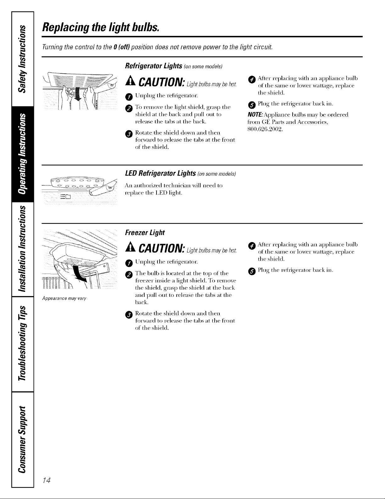
Replacingthelightbulbs.
Turning the control to the 0 (off) position does not remove power to the light circuit.
Refrigerator Lights (onsomemodels)
o o o o
Appearance may vary
CAUTION:ahtb./bsmaybe
0 Unplug the reffigeratox:
To i'einove the light shield, grasp the
shield at the back and pull out to
release the tabs at the back.
0 Rotate the shield down and then
fi)rward to release the tabs at the fl'ont
ot the shield.
LEDRefrigerator Lights (onsomemodels)
An authorized te(hnician will need to
replace the I,ED lieht
Freezer Light
Jl,CAUTION:L,gt,tb./bsr.aybet,o
0 Unplug the refiigeratox:
@ The 1)ulb is located at the top of the
fl'eezer inside a light shield. To remove
the shield, grasp the shield at the back
and pull out to release the tabs at the
1)ack.
_Mter replacing Mth an appliance bull)
of the same or lower wattage, replace
the shield.
0 Plug the refiigerator back in.
NOTE:Appliance bull)s ma_ be ordered
fl'om (;E Parts and Accessories,
800.626.2002.
0 _dter replacing xfith an appliance bull)
of the same or lower wattage, replace
the shield.
Plug the refrigerator back in.
14
Rotate the shield down and then
fiwward to release the tabs at the fl'ont
of the shield.

Trimkits and decoratorpanels.
For panel required models
Read these instructionscompletely and carefully.
Before YouBegin
Some models are equipped with trim kits that aflow you to install door panels. Youcan order
pre-cut black or white decorator panels from GE Parts and Accessories, 800.626.2002, or you can
add wood panels to match your kitchen cabinets.
Panels less than 1/4" (6 mm)thick
_,_]_en installing wood panels less than l/4" (6 ram) thick, you need to create a filler panel, such as l/8"
cardboard, that will fit between the face of the door and the wood panel. If you are installing the pre-cut
decorator panels, pre-cut filler panels are included in the kit. The combined thickness of the decorator
or wood panel and the filler panel should be 11/32" (8.7 ram) with the panel itself being no larger than
1/4" (6 ram).
Panels1/4"tlfickor less
1/4" max
The handle and the top and bottom tt_im stand in front of the sm'ii_ce of the do(m which requires that the
filler be smaller in lenoth_ and width than the panel. Use the guidelines below and tape the filler onto the
back of the panel.
LeftFreshFoodDoor
RightFreshFoodDoor
_L
Filler
Panel
FreezerDoor
Filler
Panel
Filler
Panel A ]5

Trimkits anddecoratorpanels.
3/4" (19 mm) or Raised Panel
A raised panel design screwed or glued to a ]/4" (6 ram) thick backing, or a 3/4" (] 9 ram) routed board
can be used, The raised portion of the panel must be tid)_icated to permit clearances of at least 2" (5,1 cm)
fl'om the handle side fin" fingertip clearance,
Panels thicker than 1/4" (6 ram), up u) 3/4" (19 ram) max., will require that the outer 5/16" (8 ram) ot
panel pei-hneter be no thicker than 1/4" (6 ram).
Weightlimitations for custom panels:
Fresh Food 10 Ibs. (4.5kg)max. for each door
Freezer Door 18 Ibs. (8kg)max.
Panelsthickerthan1/4" (6ram)
1/4" (6IT,e}
ThickBacking
16"(8 mm)
1/4" (6lem)max
3/4" (19ram)
Dimensions for Custom Wood Panels
. ..... 1/8"
,"'_11_ (3mini,.. LeftFreshFoodDoor
] "-
",I/4" ""
(6rare)
5/16"
mMmumat
1/4" (6 ram)
thickness
Top,left and
bottoro
Raisedportion
of panel
r"
2"(5.1 cm)
Clearance
HandleSide
Appearance
Panel
2" (51ram)
minimumat
1/4" (6 ram)
thickness
Handleside
3815/16"
(98.9cm)
2"(51 ram)
[TUnlITlUm at
1/4" (6ram)
thickness
Handleside
Raisedportion/"I"
of panel
(19mm)
Refrigerator
Door
RightFreshFoodDoor
1/8...... -.
13rare/
/ "_, .(6 lem)
5/16"(8 ram)
minhYlumat
1/4" (6ram)
thickness
Top,rightand
bottom
I
1629/32" (42.9cm)_1
2" (51 rnm)minimuroat
1/4" (6ram)thickness
Handleside
5/16" (8 ram)minimum
at 1/4" (6lem)thickness
Left,right and
bottomsides Raised
portion
ofpanel
FreezerDoor
1629/32" (42.9cm)
16 "',_1F_ 1/4)' 1'/4" _ I_ /
""...... (6 rare) (6mm)....... "

Installation
Refrigerator
Instructions
I Questions? Call 800.GE.CARES (800.432.2737) or Visit our Website at: ge.com
BEFORE YOU BEGIN
Read these instructions completely and carefully,
• IMPORTANT- Save these instructions for
local inspector's use.
• IMPORTANT- Observeallgoverning
codes and ordinances.
• Note to Installer- Be sure to leave these
instructions with the Consumer.
• Note to Consumer- Keep these instructions for
future reference.
In Canada, call 1.800.561.3344 or Visit our Website at: www.geappliances.ca
MATERIALS YOU MAY NEED (not included)
Lag Bolts Anchor Sleeves
Drill Bit Appropriate for Anchors
For Anti-lip Bracket Mounted on CONCRETEFloors 0nly
Models 21 and 25
TOOLS YOU MAY NEED
° Skill level- Installation of this appliance requires
basic mechanical skills.
• Completion time - Refrigerator Installation
20 minutes
Water Line Installation
30 minutes
Adjustable Wrench Ratchet/Driver
I
3/8" and 5/16" Socket
Anti--I]p Bracket Installation
20 minutes
• Proper installation is the responsibility of the
installer.
• Product failure due to improper installation is not
covered under the Warranty.
PREPARATION
MOVING THE REFRIGERATOR INDOORS
If the refrigerator will not fit through a doorway, the
refrigerator door and freezer drawer can be removed,
° To remove the refrigerator door, see Step 1 in the
Reversing the Door Swing section.
• To remove the freezer drawer, see the Removing
the Freezer Drawer section.
WATER SUPPLY TO THE ICEMAKER AND
DISPENSER (ON SOME MODELS)
If the refrigerator has an icemaker, it will have
to be connected to a cold water line. A GE water
supply kit (containing tubing, shutoff valve, fittings
and instructions) is available at extra cost from
your dealer, by visiting our Website at ge.com (in
Canada at www.geappliances.ca) or from Parts and
Accessories, 800.626.2002 (In Canada 1.888.261.3055).
1/4" Outer Diameter
Compression Nut
and Ferrule (sleeve)
(icemaker models only)
3/32", 1/8" and 1/4"Allen
1/8" Drill Bit and
Electric or Hand Drill
Pencil
Wire Cutters
Phillips Head Screwdriver
wrenches
Tape measure
1/4" Nut Driver
Level
17

Installation Instructions
INSTALLING THE ANTI-TIP FLOOR BRACKET (on 21 ft. models)
WARNING
O
Under certain circumstances, this refrigerator
can tip forward,
Injury to persons can result,
Install Anti-Tip Bracket packed with this
refrigerator,
[] MEASURE CABINET OPENING
AVAILABLE VS. REFRIGERATOR
WIDTH
Measure width of cabinet opening where
refrigerator will be placed, W.
Be sure to account for any countertop
overhang, baseboard thickness and any
clearance desired. Width, W, should not
be less than 36 inches. The refrigerator
will be placed approximately in the
middle of this opening.
Baseboard
Thickness
or Countertop
Overhang
(Whichever
Is Greater)
Plus Any
Desired
Clearance
RH Side
I
i
I
REFRIGERATOR
[
Rear Wall
W +1
_'_I I_-
4_
Front
LOCATING THE ANTI-TIP
[]
FLOOR BRACKET
Place the anti-tip floor bracket Iocator
[]
template (included inside the anti-tip kit)
onto the floor up against the rear wall,
within W, and in line with the desired
location of the RH side of the refrigerator
(see Figure 1).
Figure 1 - Installation Overview
2 Wall Holes
Bracket
on the _s_ RH Side of Locator
Refrigerator / Refrigerator Template Sheet
[] Place the anti-tip floor bracket onto the
Iocator template with its RH floor holes
lined up with the floor holes indicated
on the template sheet, approximately 71/4"
from the edge of the sheet or the RH side
of the refrigerator.
[] Hold down in position and use the anti-tip
floor bracket as a template for marking
the holes based upon your configuration
and type of construction as shown in Step
3. Mark the hole locations with a pencil,
nail or awl.
NOTE:
• It is REQUIRED to use at least 2 screws
to mount the floor bracket (one on each
side of the anti-tip floor bracket). Both
must be into either the wall or the floor.
Figure 2 indicates all the acceptable
mounting configurations for screws.
Identify the screw holes on the anti-tip
floor bracket for your configuration,
18

Installation Instructions
[] LOCATING THE ANTI-TIP
FLOOR BRACKET (cont.)
Figure 2 - Acce.ptable Screw
Placement Locations
Preferred Installation -
Minimum Acceptable #1- Minimum Acceptable #2-
Wood
I
i i
i
Wall Plate Stud Wood Floor
Minimum Acceptable #3 -
Concrete Floor
Preferred Installation -
Concrete
i i
[] ANTI-TIP BRACKET INSTALLATION
[] WOOD Wall and Floor Construction:
• Drill the appropriate number of 1/8"
pilot holes in the center of each floor
bracket hole being used (a nail or awl
may be used if a drill is not available)
AND remove the Iocator template from
the floor,
• Mount the anti-tip floor bracket by
fastening the 2, or preferably 4, #10-16
hex-head screws tightly into place as
illustrated in Figure 3.
Figure 3- Attachment to
Wall and Floor
2 Screws Floor [-] Wall
RearRH Must Enter Bracket H
Corner of the Wood or \ I I
Refrlgerator.,j_ Metal Stud _ "_, H Wall
[] CONCRETE Wall and Floor Construction:
• Anchors required (not provided):
4 each 1/4" x 1 1/2" lag bolts
4 each 1/2" O.D. sleeve anchors
• Drill the recommended size holes for
the anchors into the concrete at the
center of the holes marked in Step 2.
• Install the sleeve anchors into the drilled
holes. Place the anti-tip floor bracket as
indicated in Step 2. Remove the Iocator
template from the floor.
• Install the lag bolts through the anti-tip
floor bracket and tighten appropriately.
[] WOOD Wall and TILE Floor Construction:
• For this special case, locate the 2 wall
holes identified in Fig. 1. Drill an angled
1/8" pilot hole (approx. as shown in
Fig. 3) in the center of each hole.
• Mount the anti-tip floor bracket using
the Minimum Acceptable Installation #1,
as illustrated in Fig. 2.
[] POSITIONING THE REFRIGERATOR
TO ENGAGE THE ANTI-TIP FLOOR
AND BASE BRACKETS
[] Before pushing the refrigerator into the
opening, plug the power cord into the
receptacle and connect waterline (if
equipped). Check for leaks.
[] Locate the refrigerator's RH side and
move back approximately in line with the
RH side of the cabinet opening, W. This
should position the anti-tip floor bracket
to engage the anti-tip base bracket on the
refrigerator.
[] Gently roll the refrigerator back into
the cabinet opening until it comes
to a complete stop. Check to see if
the refrigerator front lines up with the
cabinet front face. If not, carefully rock
the refrigerator forward and backward
until engagement occurs and you notice
that the refrigerator is fully pushed up
against the rear wall.
[] OPTIONAL: Adjust the rear (and front)
wheel height settings to fully engage the
rear anti-tip brackets, while also aligning
the refrigerator front with the cabinet
front face.
19
NOTE:
If you pull the refrigerator out and away from
the wall for any reason, make sure the anti-tip
floor bracket is engaged when the refrigerator
is pushed back against the rear wall.

Installation Instructions
INSTALLING THE REFRIGERATOR
REFRIGERATOR LOCATION
• Do not install the refrigerator where the
temperature will go below 60°F (16°C) because it
will not run often enough to maintain proper
temperatures.
• Do not install the refrigerator where the
temperature will go above IO0°F (37°C) because it
will not perform properly.
• Install it on a floor strong enough to support it fully
loaded.
CLEARANCES
Allow the following clearances for ease of installation,
proper air circulation and plumbing and electrical
connections.
Standard Depth Counter Depth
Models Models
Sides 1/8" (3 mm) 1/8" (3 mm)
Top 1" (25 mm) 1" (25 mm)
Back 1" (25 mm) 1/2" (13 mm)
REMOVE TOP CAP (cont.) (onsomemodels)
REINSTALL DOORS, DRAWERS AND TOP CAP
[] Carefully lower the door onto the center hinge.
Reinstall top hinge. NOTE: Ensure the door is
properly aligned to the case top to avoid
readjustment of the door during top cap
reinstallation.
[] Place cap over the top of the refrigerator. Reinstall
the original screws in the top and back of the cap.
[] Reinstall the bottom freezer drawer. Refer to
"Replacing the Freezer Drawer" section.
REMOVE TOP CAP (onsomemodels)
• IMPORTANT NOTE: This refrigerator is34-1/2" deep.
Doors and passageways leading to the installation
location must be at least 36" wide in order to
leave the doors and handles attached to the
refrigerator while transporting it into the installation
location. If passageways are lessthan 36", the
refrigerator doors and handles can easily be scratched
and damaged. The top cap and doors can be removed
to allow the refrigerator to be safely moved indoors.
Start with Step A.
• If it is not necessary to remove doors, skip Step A.
Leave tape and all packaging on doors until the
refrigerator is in the final location.
• SKID REMOVAL: ]ilt refrigerator to each side to
remove skid.
• NOTE: Use a padded hand truck to move this
refrigerator. Place the refrigerator on the hand
truck with a side against the truck. We strongly
recommend that TWO PEOPLE move and complete
this installation.
[] Locate and remove the two Phillips head screws
on the top of the refrigerator. Remove the two
screws on each side at the rear of the top cap.
Lift off and remove top cap.
[] Remove the fresh-food door. Refer to Steps 1
through 3 of "Reversing the Door Swing" section.
[] Remove the bottom freezer drawer. Refer to
"Removing Freezer Drawer" section.
[] Move refrigerator to the installation location.
TopHingeB
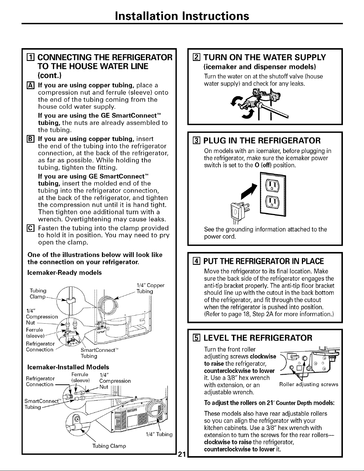
[] CONNECTING THE REFRIGERATOR
TO THE HOUSE WATER LINE
(icemaker and dispenser models)
A cold water supply is required for automatic
icemaker operation. If there is not a cold water
supply, you will need to provide one. See
Installing the Water Line section.
NOTES:
• Before making the connection to the
refrigerator, be sure the refrigerator power cord
is not plugged into the wall outlet.
• If your refrigerator does not have a water filter,
we recommend installing one if your water
supply has sand or particles that could clog the
screen of the refrigerator's water valve. Install it
in the water line near the refrigerator. If using
GE SmartConnect TM Refrigerator Tubing Kit, you
will need an additional tube (WXO8XIO002) to
connect the filter. Do not cut plastic tube to
install filter.
20
Installation Instructions
[] CONNECTING THE REFRIGERATOR
TO THE HOUSE WATER LINE
(cont.)
[] If you are using copper tubing, place a
compression nut and ferrule (sleeve) onto
the end of the tubing coming from the
house cold water supply.
If you are using the GE SmartConnect TM
tubing, the nuts are already assembled to
the tubing.
[] If you are using copper tubing, insert
the end of the tubing into the refrigerator
connection, at the back of the refrigerator,
as far as possible. While holding the
tubing, tighten the fitting.
If you are using GE SmartConnect TM
tubing, insert the molded end of the
tubing into the refrigerator connection,
at the back of the refrigerator, and tighten
the compression nut until it is hand tight.
Then tighten one additional turn with a
wrench. Overtightening may cause leaks.
[] Fasten the tubing into the clamp provided
to hold it in position. You may need to pry
open the clamp.
[] TURN ON THE WATER SUPPLY
(icemaker and dispenser models)
Turn the water on at the shutoff valve (house
water supply) and check for any leaks.
[] PLUG IN THE REFRIGERATOR
On models with an icemaker, before plugging in
the refrigerator, make sure the icemaker power
switch is set to the O (off) position.
See the grounding information attached to the
power cord.
One of the illustrations below will look like
the connection on your refrigerator.
Icemaker-Ready models
1/4" Copper
Tubing ///1
1/_lamp _'_I_
Compression
Nut _
Ferrule _
(sleeve) _
Refrigerator /_4
Connection z
Icemaker-lnstalled Models
Ferrule 1/4"
Refrigerator (sleeve) Compression
Connection --
Tubin£
_ Tubing
SmartConnect TM
Tubing
1/4" Tubing
Tubing Clamp
[] PUT THE REFRIGERATORIN PLACE
Move the refrigerator to its final location. Make
sure the back side of the refrigerator engages the
anti-tip bracket properly. The anti-tip floor bracket
should line up with the cutout in the back bottom
of the refrigerator, and fit through the cutout
when the refrigerator is pushed into position.
(Refer to page 18, Step 2A for more information.)
[] LEVEL THE REFRIGERATOR
Turn the front roller
adjusting screws clockwise
to raise the refrigerator,
counterclockwise to lower
it. Use a 3/8" hex wrench
with extension, or an Roller adjusting screws
adjustable wrench.
To adjust the rollers on 21' Counter Depth models:
These models also have rear adjustable rollers
so you can align the refrigerator with your
kitchen cabinets. Use a 3/8" hex wrench with
extension to turn the screws for the rear rollers--
clockwise to raise the refrigerator,
counterclockwise to lower it.
21
Installation Instructions
INSTALLING THE REFRIGERATOR (cont.)
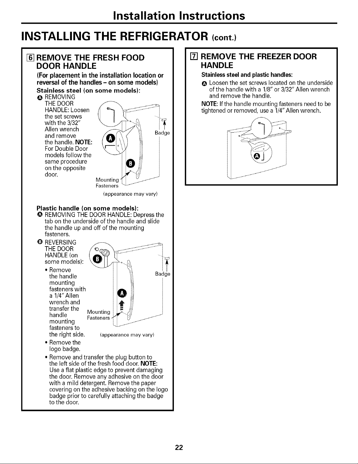
[] REMOVE THE FRESH FOOD
DOOR HANDLE
(For placement in the installation location or
reversal of the handles - on some models)
Stainless steel (on some models):
@ REMOVING
THE DOOR
HANDLE: Loosen
the set screws
with the 3/32"
Allen wrench
and remove Badge
the handle. NOTE:
For Double Door
models follow the
same procedure
on the opposite
door.
Mounting
Fasteners
(appearance may vary)
Plastic handle (on some models):
@ REMOVING THE DOOR HANDLE: Depress the
tab on the underside of the handle and slide
the handle up and off of the mounting
fasteners.
O REVERSING
THE DOOR
[] REMOVE THE FREEZER DOOR
HANDLE
Stainless steel and plastic handles:
@ Loosen the set screws located on the underside
of the handle with a 1/8" or 3/32" Allen wrench
and remove the handle.
NOTE: If the handle mounting fasteners need to be
tightened or removed, use a 1/4" Allen wrench.
some models):
* Remove
the handle
mounting
fasteners with
a 1/4" Allen
wrench and
transfer the
handle Mounting
mounting
fasteners to
the right side. (appearance may vary)
" Remove the
logo badge.
, Remove and transfer the plug button to
the left side of the fresh food door. NOTE:
Use a flat plastic edge to prevent damaging
the door. Remove any adhesive on the door
with a mild detergent. Remove the paper
covering on the adhesive backing on the logo
badge prior to carefully attaching the badge
to the door.
Fasteners
ild
22

Installation Instructions
[] ATTACH THE FRESH FOOD
DOOR HANDLE
Stainless steel handle:
Attach the handle
to the handle
mounting
fasteners and
tighten the set
screws with a
3/32" Allen
wrench. Mounting
NOTE: For Double Fasteners
Door models
follow the same
procedure on the
opposite door.
(appearance may vary)
Plastic handle:
O Attach the handle to the handle mounting
fasteners by aligning the slots with the handle
mounting fasteners.
O Slide it down until it is firmly locked into
position.
[] ATTACH THE FREEZER DOOR
HANDLE
Stainless steel and plastic handles:
O Attach the handle firmly to the mounting
fasteners and tighten the set screws on the
bottom of the handle with a 1/8" or 3/32"
Allen wrench.
(appearance may vary)
Slots on back
of handle
O
Mounting
fasteners
(appearance may vary)
23

Installation Instructions
INSTALLING THE REFRIGERATOR (cont,)
I_] LEVEL THE REFRIGERATOR
The leveling legs have 2 purposes:
1) Leveling legs adjust so the refrigerator
is firmly positioned on the floor and
does not wobble.
2) Leveling legs serve as a stabilizing
brake to hold the refrigerator securely
in position during operation and
cleaning. The leveling legs also prevent
the refrigerator from tipping.
[] Remove the grille by removing the two
Phillips head screws.
[] Turn the leveling legs clockwise to raise the
refrigerator, counterclockwise to lower it.
[] SET THE CONTROLS
Set the controls to the recommended
setting.
[.ECOMME.OEOCO.T.OLSE ..OS]
L
reel
0 "FIS RECOMMENDED 37'F IS RECOMMENDED
REMOVE PACKAGING
[]
START ICEMAKER
(icemaker models)
A) Remove all tape, foam and protective
packing from shelves and drawers.
B) Remove the tie downs from the freezer
baskets.
C) Place half width basket onto drawer
slides. See About the freezer section
for instructions.
Set the icemaker power switch to the
I (on) position. The icemaker will not
begin to operate until it reaches its
operating temperature of 15°F (-9°C)
or below. It will then begin operation
automatically. It will take 2-3 days to
fill the ice bin.
plrj
CAUTION: Toavoidpossible
personal injury or property damage, the
leveling legs must be firmly touching
the floor.
[] Replace the base grille by inserting the two
Phillips head screws.
NOTE:
In lower water pressure conditions, the
water valve may turn on up to 3 times
to deliver enough water to the icemaker.
24

Installation Instructions
REMOVING THE FREEZER DRAWER (on some models)
The freezer drawer can be removed, if needed,
to fit through tight areas.
Read these instructions completely and carefully.
[] REMOVE THE BASKET
[] Open the freezer drawer until it stops.
[] Cut the 2 wire ties off of the basket with
wire cutters.
[] The freezer basket rests inside 4 tabs on
the freezer slides. Lift the basket up and
out of the 4 tabs.
[] Tilt the front up and lift the entire basket
up and out of the drawer.
Q
\\\\\\\
\
[] REMOVE THE BASE GRILLE
(if needed)
If, after removing the freezer drawer and
refrigerator door, the refrigerator will still
not fit through a doorway, the base grille
can be removed.
[] Remove the base grille by removing the
2 Phillips head screws.
[] REMOVE THE DRAWER FRONT
FROM THE SLIDES
[] Remove the 10 hex head screws from the
door and remove the door.
Q DO NOT remove the torx screws
from the rail assemblies.
\
DO NOT remove
torx screws
\
Rail Assembly
[] Set the drawer front non-scratching
surface.
[] Push the rail assemblies back into the
cabinet.
on a
25
Installation Instructions
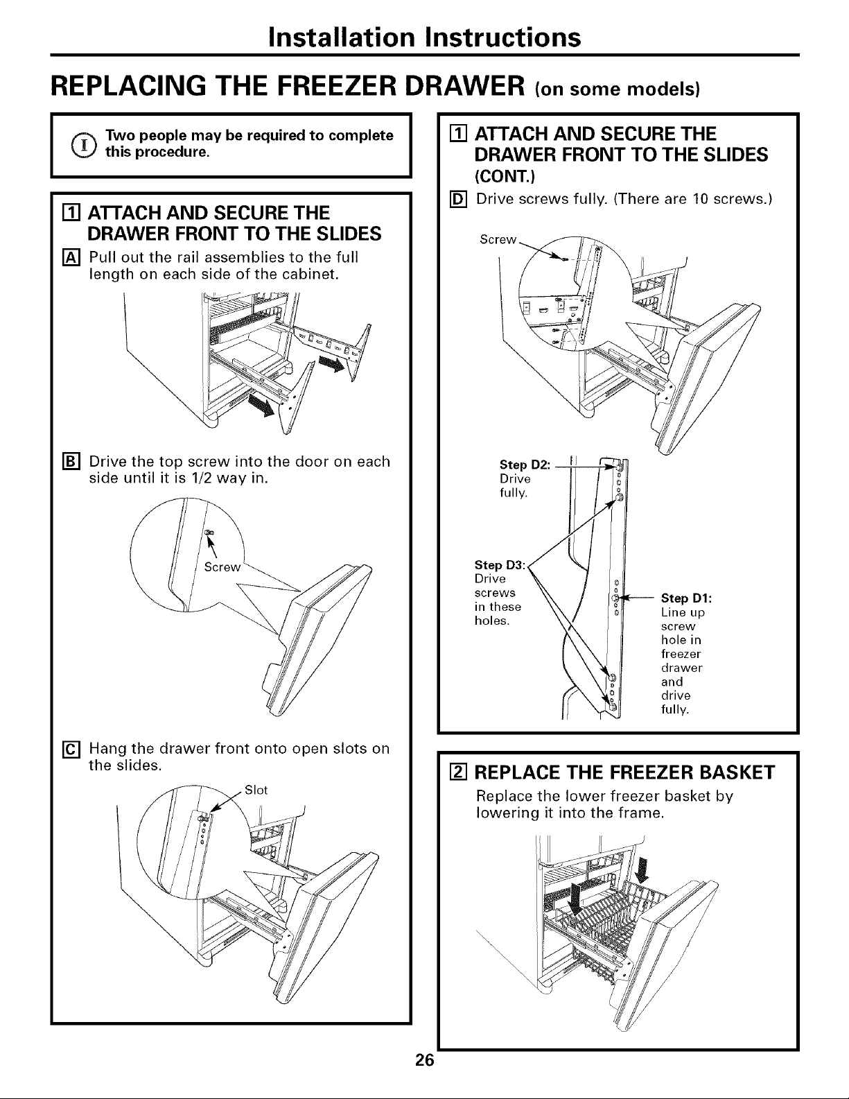
REPLACING THE FREEZER DRAWER (on some models)
o Two people may be required to complete
I
this procedure.
[] ATTACH AND SECURE THE
DRAWER FRONT TO THE SLIDES
[] Pull out the rail assemblies to the full
length on each side of the cabinet.
[] Drive the top screw into the door on each
side until it is 1/2 way in.
[] ATTACH AND SECURE THE
DRAWER FRONT TO THE SLIDES
(CONT.)
[] Drive screws fully. (There are 10 screws.)
Step D2:
Drive
fully•
[] Hang the drawer front onto open slots on
the slides.
•Slot
Step D3:
Drive
screws
in these
holes.
-- Step DI:
Line up
screw
hole in
freezer
drawer
and
drive
fully.
[] REPLACE THE FREEZER BASKET
Replace the lower freezer basket by
lowering it into the frame.
_\\\\\
\
\
26
Installation Instructions
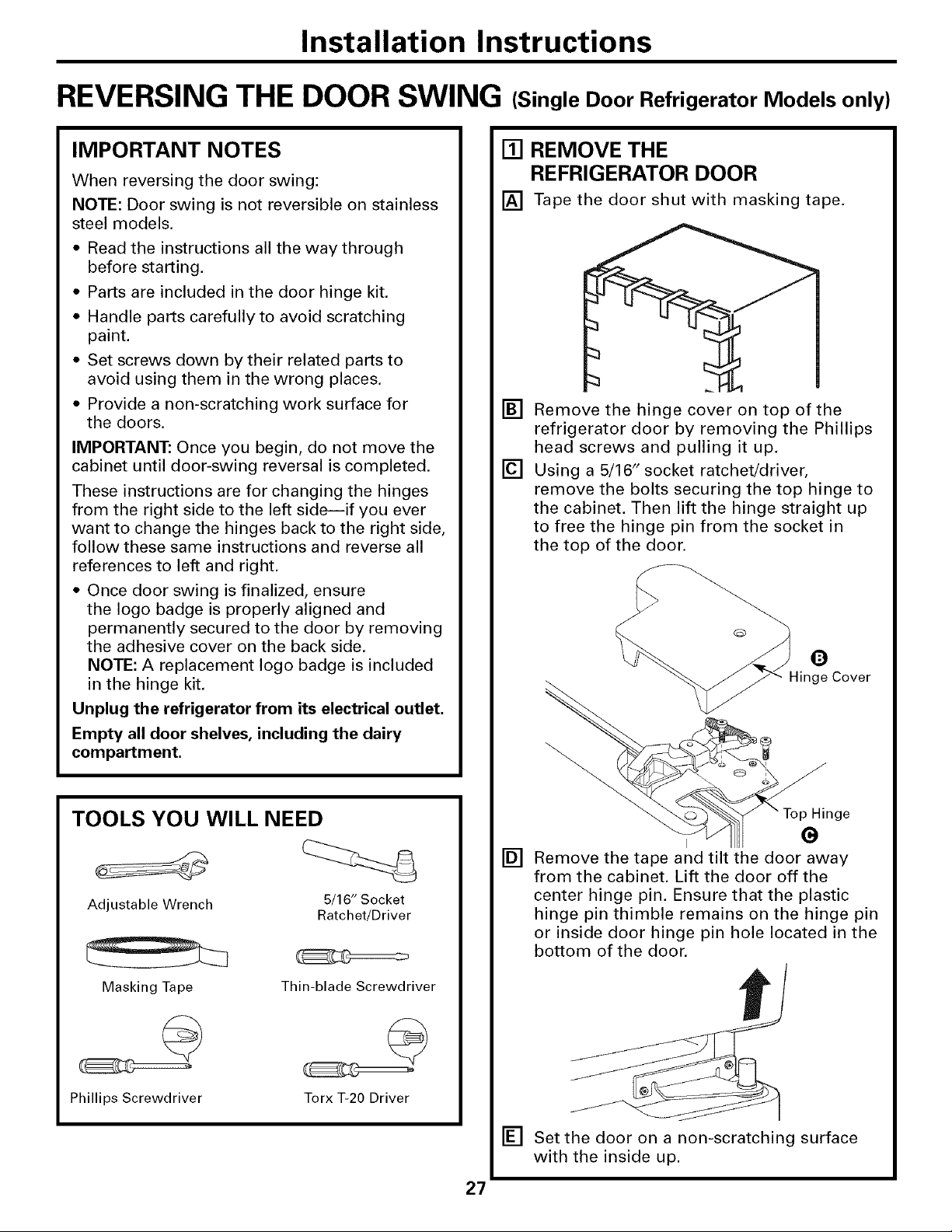
REVERSING THE DOOR SWING (Single Door Refrigerator Models only)
IMPORTANT NOTES
When reversing the door swing:
NOTE: Door swing is not reversible on stainless
steel models.
* Read the instructions all the way through
before starting.
= Parts are included in the door hinge kit.
• Handle parts carefully to avoid scratching
paint.
• Set screws down by their related parts to
avoid using them in the wrong places.
• Provide a non-scratching work surface for
the doors.
IMPORTANT: Once you begin, do not move the
cabinet until door-swing reversal is completed.
These instructions are for changing the hinges
from the right side to the left sideiif you ever
want to change the hinges back to the right side,
follow these same instructions and reverse all
references to left and right.
• Once door swing is finalized, ensure
the logo badge is properly aligned and
permanently secured to the door by removing
the adhesive cover on the back side.
NOTE: A replacement logo badge is included
in the hinge kit.
Unplug the refrigerator from its electrical outlet.
Empty all door shelves, including the dairy
compartment.
[] REMOVE THE
REFRIGERATOR DOOR
[] Tape the door shut with masking tape.
[] Remove the hinge cover on top of the
refrigerator door by removing the Phillips
head screws and pulling it up.
[] Using a 5/16" socket ratchet/driver,
remove the bolts securing the top hinge to
the cabinet. Then lift the hinge straight up
to free the hinge pin from the socket in
the top of the door.
O
-linge Cover
TOOLS YOU WILL NEED
Adjustable Wrench
Masking Tape
Phillips Screwdriver
Thin-blade Screwdriver
5/16" Socket
Ratchet!Driver
Torx T-20 Driver
i G
[]
Remove the tape and tilt the door away
from the cabinet. Lift the door off the
center hinge pin. Ensure that the plastic
hinge pin thimble remains on the hinge pin
or inside door hinge pin hole located in the
bottom of the door.
[] Set the door on a non-scratching surface
with the inside up.
27
Hinge

Installation Instructions
REVERSING THE DOOR SWING (cont.)
[] REMOVE CENTER HINGE
Using a 5/16" socket ratchet/driver,
remove the bolts securing the center
hinge to the cabinet. Set the hinge
and bolts aside.
[] INSTALL CENTER HINGE
[] Transfer the plug button and screw hole
cover in the hinge holes on the left side to
the right side.
TRANSFER REFRIGERATOR
[]
DOOR STOP
[]
Remove the door stop on right side of
the bottom of the refrigerator door by
removing the two screws.
[]
Move the plastic hinge hole thimble to the
opposite hole.
[]
Install the door stop on the left side,
making sure to line up the screw holes
in the door stop with the holes in the
bottom of the door.
Bottom of Bottom of
Refrigerator Door Refrigerator Door
(Right Side) (Left Side)
[] Install the center hinge from the kit on the
left side.
NOTE: A new hinge will be required for the
left side (supplied in the door hinge kit).
ITI TRANSFER REFRIGERATOR
DOOR HANDLE TO RIGHT
Refer to Remove the Fresh Food Door
Handle and Attach the Fresh Food Door
Handle sections for instructions.
28

Installation Instructions
[] REHANG REFRIGERATOR DOOR
[] Lower the refrigerator door onto the
center hinge pin. Ensure that the plastic
hinge pin thimble is on the center hinge
pin or inside door hinge pin hole located
in the bottom of the door.
[]
Insert the top hinge pin into the hinge hole
on top of the refrigerator door. Make sure
the door is aligned with the cabinet.
Attach the hinge to the top of the cabinet
loosely with the bolts.
[]
Make sure the gasket on the door is
flush against the cabinet and is not folded.
Support the door on the handle side and
make sure the door is straight and the gap
between the doors is even across the
front. While holding the door in place,
tighten the top hinge bolts. Replace the
hinge cover.
[] INSTALL THE LOGO BADGE
Remove the adhesive backing paper
and align the pins on the back of the
badge with the holes in the door. Apply
pressure to the badge to ensure it sticks
to the door.
_::...
29

Installation Instructions
REMOVING THE DOORS (Double Door Refrigerator Models only)
IMPORTANT NOTES
NOTE: Door swing is not reversible.
• Read the instructions all the way through
before starting.
• Handle parts carefully to avoid scratching
paint.
• Set screws down by their related parts to
avoid using them in the wrong places.
• Provide a non-scratching work surface for
the doors.
IMPORTANT: Once you begin, do not move
the cabinet.
These instructions are for removing the
doors.
Unplug the refrigerator from its electrical
outlet.
Empty all door shelves, including the dairy
compartment.
TOOLS YOU WILL NEED
[] REMOVE THE
REFRIGERATOR DOORS
[] Tape the doors shut with masking tape.
(for water dispenser models)
[] Start with right-hand door first: Remove
the screw securing the center hinge cover,
lift the hinge cover and place to the side
on top of the refrigerator.
Adjustable Wrench 3/8" and 10 mm Socket
Masking Tape
Phillips Screwdriver
Ratchet/Driver
Thin-blade Screwdriver
(for water dispenser models)
[] Remove water coupling and power
coupling.
Water Coupling o
Remove the metal spring _ '_
clip. Use a screwdriver to --_[_----_ " -_
push the red plastic locking "_ /
clip down and off. _" I _-_-_
Power Coupling
Black mark
flush with
collar assembly
Pull apart power
coupling to
disconnect
30
 Loading...