

GE PDS22xxP series, GBS20xxP series, GBS22xxP series, PDS20xxP series Technical Service Manual
GE Consumer & Industrial
TECHNICAL SERVICE GUIDE
2003 Electronic Bottom-Mount
Refrigerators
MODEL SERIES:
GBS22_ _P
GBS20_ _P
PDS22_ _P
PDS20_ _P
PUB # 31-9112 1/04

IMPORTANT SAFETY NOTICE
The information in this service guide is intended for use by
individuals possessing adequate backgrounds of electrical,
electronic, and mechanical experience. Any attempt to repair a
major appliance may result in personal injury and property
damage. The manufacturer or seller cannot be responsible for the
interpretation of this information, nor can it assume any liability in
connection with its use.
W ARNING
To avoid personal injury, disconnect power before servicing this
product. If electrical power is required for diagnosis or test
purposes, disconnect the power immediately after performing the
necessary checks.
RECONNECT ALL GROUNDING DEVICES
If grounding wires, screws, straps, clips, nuts, or washers used
to complete a path to ground are removed for service, they must
be returned to their original position and properly fastened.
All rights reserved. This service guide may not be reproduced in whole or in
part in any form without written permission from the General Electric Company.
GE Consumer & Industrial
Technical Service Guide
Copyright © 2004
– 2 –

Table of Contents
Airflow (Cabinet Interior).................................................................................................................. 6
Air Flow Tower and Damper ........................................................................................................ 11
Component Locator Views ............................................................................................................ 9
Components................................................................................................................................10
Control Diagnostics ..................................................................................................................... 18
Control Features ........................................................................................................................... 8
Diagnostics Chart ....................................................................................................................... 19
Doors ............................................................................................................................................ 4
Door Gaskets .............................................................................................................................. 17
Door Handles ................................................................................................................................ 4
Electronic Control Panel................................................................................................................8
Evaporator Fan ............................................................................................................................ 13
Evaporator Thermistor ................................................................................................................ 13
Evaporator Thermostat ...............................................................................................................14
Freezer Drawer and Slides .........................................................................................................16
Fresh Food and Freezer Thermistors ......................................................................................... 12
Fresh Food and Freezer Light Thermostats ............................................................................... 15
Icemaker Ready Models .............................................................................................................. 12
Illustrated Parts Catalog .............................................................................................................. 24
Installation .....................................................................................................................................4
(Encoder) .............................................................................................................................10
Knob
(Encoder) Control Panel ........................................................................................................ 8
Knob
Nomenclature ................................................................................................................................7
Schematics ................................................................................................................................. 22
Strip Circuits ................................................................................................................................ 20
Technical Data...............................................................................................................................6
Troubleshooting ........................................................................................................................... 18
Warranty......................................................................................................................................30
Water Filter................................................................................................................................. 11
– 3 –
Installation
Doors
The swing direction of the fresh food door and the
freezer door can be reversed on all models except
stainless steel.
Stainless steel models must be ordered as left or
right door swing.
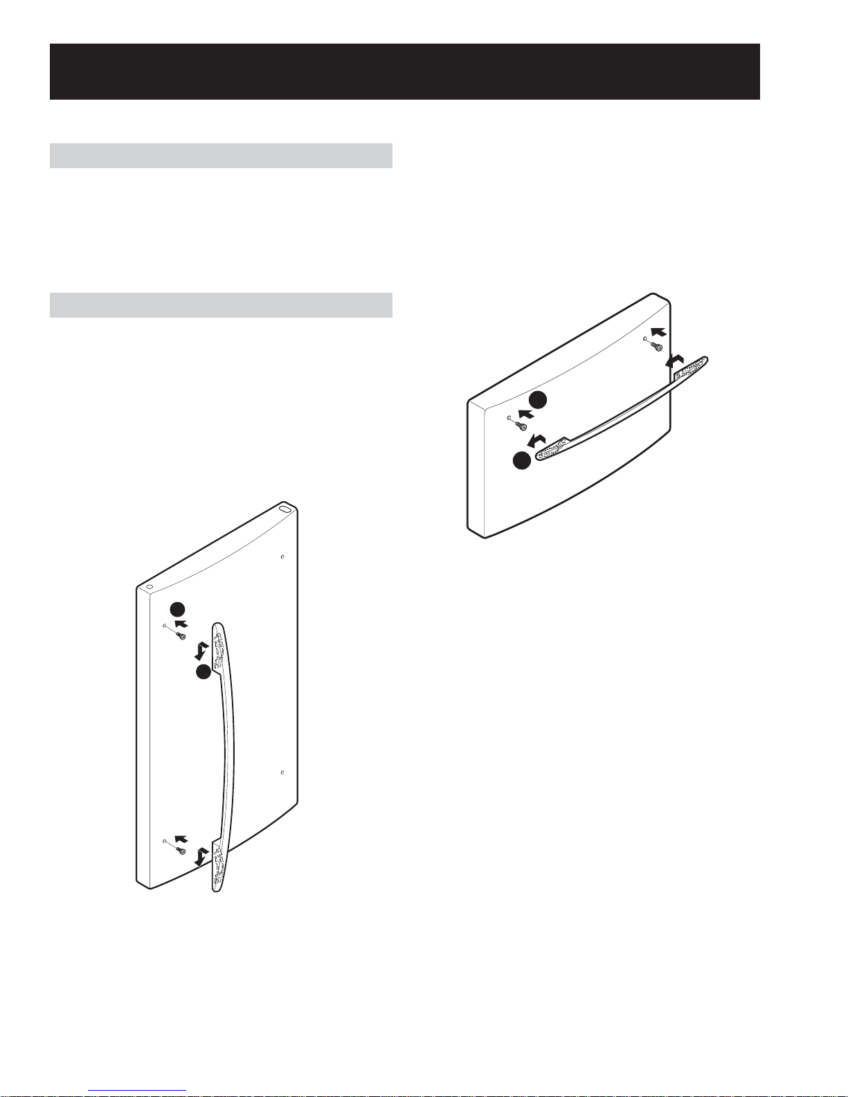
Door Handles
Removal and Replacement
Fresh Food Door
1. Lift the fresh food compartment door handle
firmly upward and off of the 2 door mounting
screws.
2. Reverse the above procedure to reinstall.
Freezer Door
1. Install 2 door mounting screws on the freezer
compartment door.
2. Insert the door handle onto the door mount
screws and pull the handle firmly to the left.
1
2
1
2
Note: The door handle can be installed
incorrectly. Make sure the curved side of the
handle is toward the outside edge of the door.
Note: The door handle can be installed
incorrectly. Make sure the handle is curved
upward and is locked in place. A properly installed
handle will be centered on the door.
– 4 –
Troubleshooting Tips - Handle Installation
Problem Possible Causes What To Do
Handle too hard to
install/Handle requires
excessive force to
install
Loose handle/Handle
makes rattling noise at
attachment
Mounting bolts too tight. Remove the handle. Loosen the mounting bolts
slightly so that the handle will snap into place
when installed.
Defective mounting bracket or
bolts.
Loose mounting bolts.
Freezer handle is installed
backwards.
Remove handle. Check for defective mounting
brackets or bolts. If defective, replace. Install
handle according to Installation Instructions.
If the handle installs properly (slides on and
locks/snaps into place) but is loose, remove the
handle and tighten the mounting bolts. Use a
10mm socket and ratchet or wrench. Do not use a
screwdriver as it will not provide enough torque
for proper tightening. Reinstall handle according
to Installation Instructions included with the
handle.
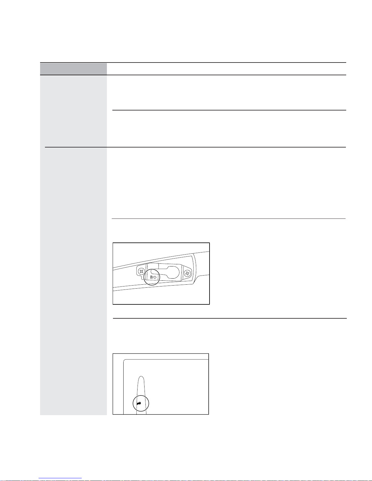
Remove handle. Check for correct mounting
brackets on the handle. There is a right bracket
(R) and a left bracket (L). The handle has the
word “RIGHT” printed in the bracket cavity. The
“R” bracket should be installed in the bracket
cavity marked “RIGHT”. The “L” bracket should
be installed on the opposite side. Reinstall handle
according to Installation Instructions.
Fresh Food handle is mounted upside
down or incorrectly relative to the
curve of the Fresh Food door.
Make certain that the arrow label on the handle
is pointing at the center of the unit. To verify, the
handle should look straight from a distance (not
slanted to the side).
– 5 –
Technical Data
ELECTRICAL SPECIFICA TIONS
Temperature Control (Position 5)....................... 32 - 4°F
Defrost Control... 60 hrs @ 40 mins with no door opening
Overtemperature Thermostat....................... 140 - 110°F
Defrost Thermistor.................................................70°F
Electrical Rating: 115V. AC, 60 Hz.................1 - 5 Amp.
Maximum Current Leakage................................0.5 mA
Maximum Ground Path Resistance...............0.14 Ohms
Energy Consumption.......507 kWh/yr for 20 cu/ft models
Energy Consumption.......520 kWh/yr for 22 cu/ft models
NO LOAD PERFORMANCE
Control Position: 5-5
And Ambient of:................................................... 90°F
Fresh Food, °F..................................................32 - 42
Frozen Food, °F.................................................. -5 - 5
Percent Running Time....................................... 45 - 65
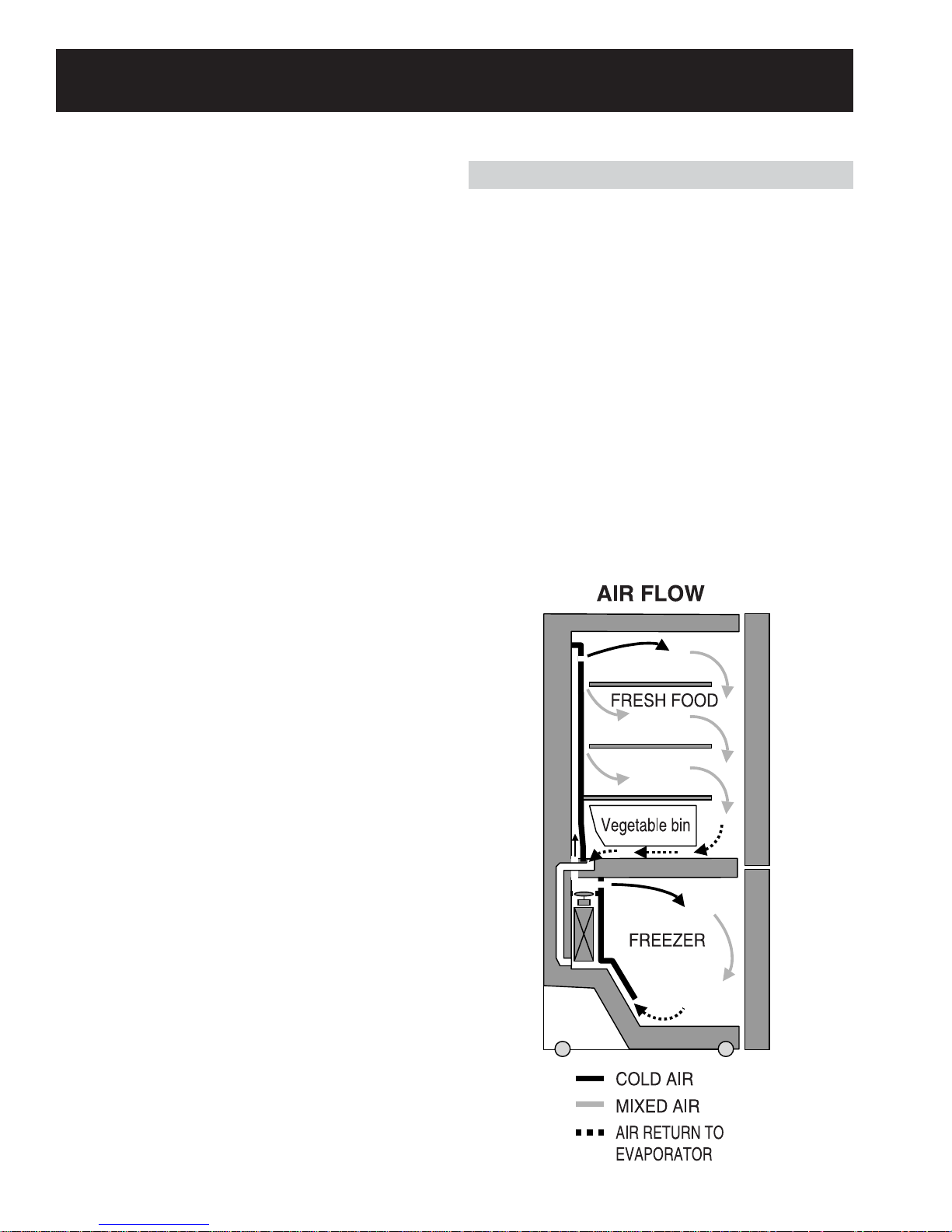
Airflow (Cabinet Interior)
The evaporator fan forces air through the
evaporator into the freezer compartment.
Air from the evaporator is also forced through the
electronic damper to the top of the air tunnel,
through the fresh food compartment, and returns
to the evaporator.
The fresh food compartment receives chilled air
through an electronic damper at the bottom, rear
of the fresh food compartment. The damper is
controlled by the main control board. When open,
the damper allows chilled air from the freezer to
move into the fresh food compartment.
Air returns from the fresh food compartment to the
freezer compartment via two vents located to the
left and right of the air tunnel.
REFRIGERA TION SYSTEM
Minimum Compressor Capacity Vacuum.............. 22 in.
Minimum Equalized Pressure
@ 70°F ................................................... 38 PSIG
@ 90°F.................................................... 49 PSIG
Refrigerant - R - 134a...................................... 4.06 oz.
Compressor .............................................. 690 BTU/hr
INSTALLATION
Clearance must be provided at top, sides and rear of the
refrigerator for air circulation.
AT TOP............................................................. 1 inch
AT SIDES................................................... 0.125 inch
AT REAR.......................................................... 1 inch
– 6 –
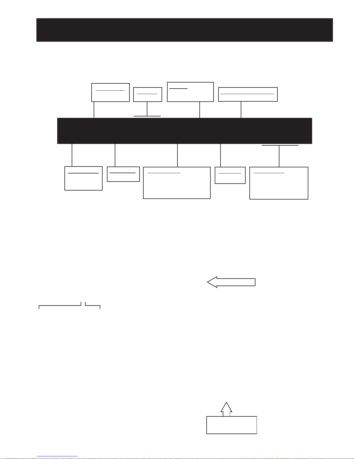
Model Number
Nomenclature
CONFIGURATION
B = DOOR
D = DRAWER
CUBIC FEET
20 or 22
ICEMAKER
B = ICEMAKER READY
C = FACTORY ICEMAKER
ENGINEERING NOMENCLA TURE
A = CONVERSION KIT
P D S 2 2 M C P A W W
BRAND/PRODUCT
G = GE
P = PROFILE (GE)
DEPTH/POWER
S = STANDARD
INTERIOR/SHELVES
H = UPGRADE GLASS
K = SPILL-PROOF GLASS
M = SPILL-PROOF/SLIDE-OUT GLASS
S = STAINLESS STEEL DOORS
MODEL YEAR
P = 2003
EXTERIOR COLOR
WW = WHITE/WHITE
SS = STAINLESS/STAINLESS
CC = BISQUE/BISQUE
BB = BLACK/BLACK
Serial Number
The first two characters of the serial number
identify the month and year of manufacture.
Example: AG123456S = January, 2004
A - JAN 2005 - H
D - FEB 2004 - G
F - MAR 2003 - F
G - APR 2002 - D
H - MAY 2001 - A
L - JUN 2000 - Z
M - JUL 1999 - V
R - AUG 1998 - T
S - SEP 1997 - S
T - OCT 1996 - R
V - NOV 1995 - M
Z - DEC 1994 - L
The letter
designating the
year repeats every
12 years.
Example:
T - 1974
T - 1986
T - 1998
Nomenclature
The nomenclature
plate is located on the
upper left wall of the
fresh food
compartment.
Mini-Manual
(Behind Base Grille)
– 7 –
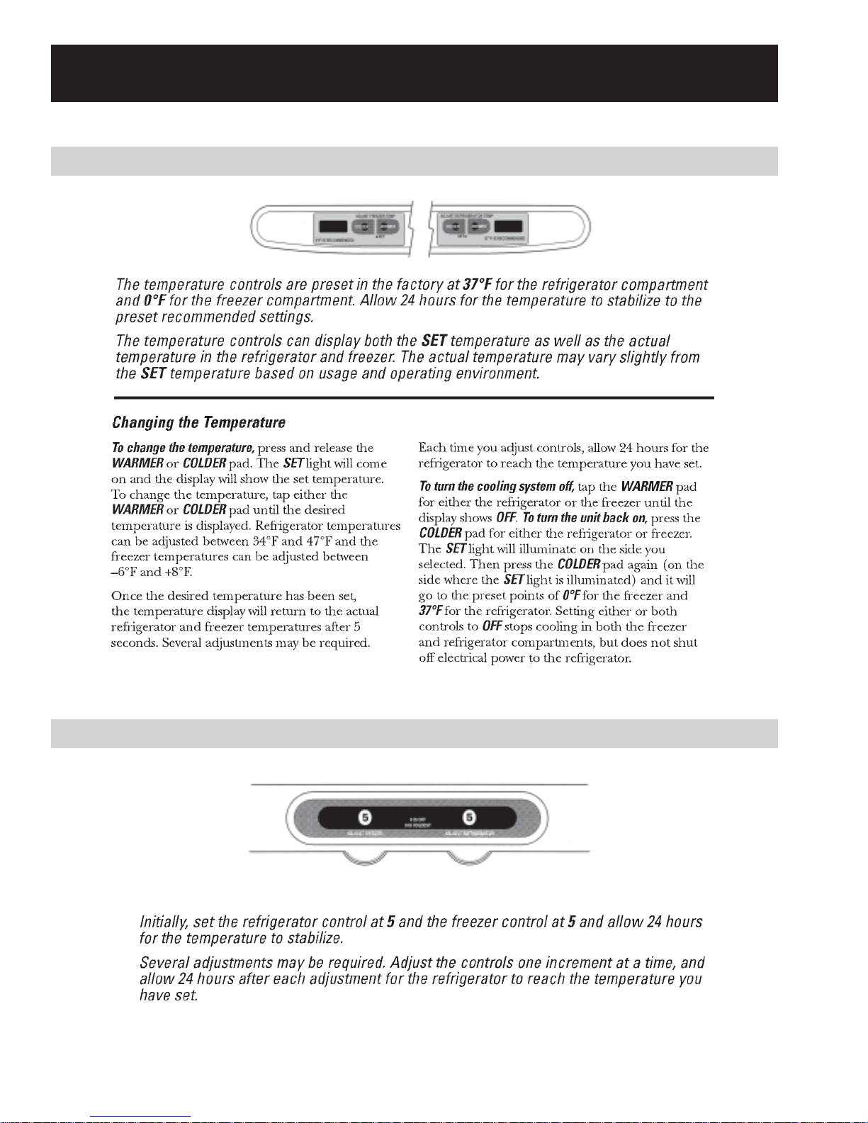
Electronic Control Panel
Control Features
Knob (Encoder) Control Panel
– 8 –
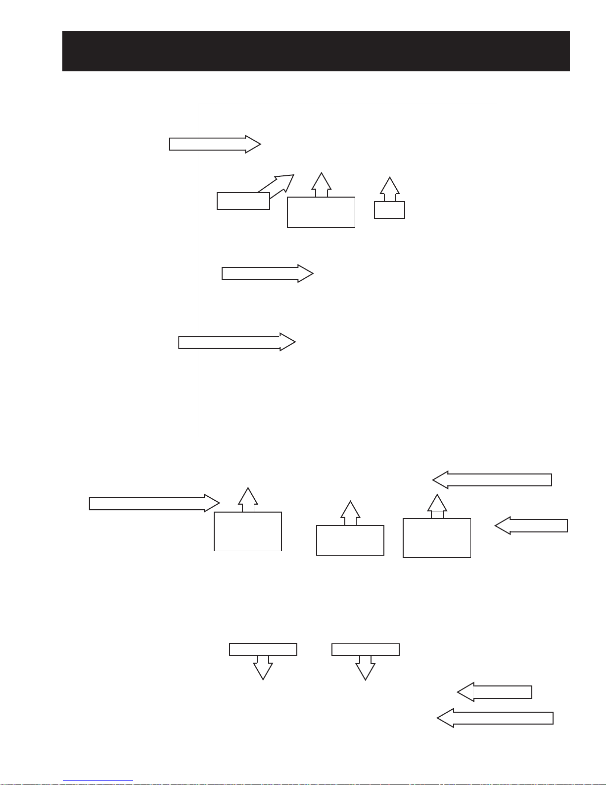
Fresh Food Section
Component Locator Views
Control Panel
Freezer Section
Thermistor
Air Flow Tower
Damper (Inside Tower)
Lights and
Thermostat
Filter
Light and Thermostat
Icemaker (When Installed)
Machine Compartment
Evaporator
Thermostat
(Behind Panel)
Compressor
Evaporator
(Behind Panel)
Condenser
– 9 –
Evaporator
Thermistor
(Behind Panel)
Condenser Fan Motor
Thermistor
Water Valve
 Loading...