

GE SDL20KCSBBS, PFS22SISDSS, PFS22SISCSS, PFS22SISBSS, PFS22SISASS Owner’s Manual
...
ge.com
Safety In_Ttructions ........... 2, 3
¢;
N
¢;
¢;
©
¢)
Operating Instruc_tions
Additional Features ............. 9
Automatic Icemaker . .......... 12
Controls .................... 4-6
Crispers and Paras ............. 10
Freezer ...................... 11
Shelves and Bins ............. 8, 9
V{ater Filter ................... 7
Care and Cleaning ........ 13-15
Installation Instructions
Installing the Refligerator . . . .l 7-91
Installing the _A'ater Line ..... 31-33
Preparing to Install
the Refligerator . .............. 16
Removing and Replacing the
Freezer Drawer . ........... 22, 23
Reversing the Door Swing
(Single Door Refiigerator
Models only) .............. 24-27
Removing and Replacing
the Doors (Double Door
Refrigerator Models only) .... 28-30
Models20 and22
Cong_lateur inl%rieur
R frig&ateurs
La section fran_aise commence a la page 47
Congelador inferior
Refrigeradores
La seccion en espa#ol empieza en la pagina 89
bb
Troubleshooting Tips ....... 34-38
Normal Operating Sounds ...... 34
Consumer Support
Consumer Support ..... Back Cover
Performance Data Sheet ........ 45
Product Registration
for Canadian Customers ..... 41,42
Product Registration
for U.S. Customers ......... .9,9,40
V{arranty fox Canadian
Customers ................... 43
Warranty fox U.S. Customers ..... 44
Write the model and serial
numbers here:
Model #
Serial #
Find these numbex_ on a label
on the right side, near the top ot
the refl'igerator compartment.
3828JL8069C
197D4618PO08 49-60452 01-06JR
iMPORTANTSAFETYiNFORMATiON.
READALLiNSTRUCTiONSBEFOREUSING.
WARNING!
Use this appliance only for its intended purpose as described in this Owner's Manual.
SAFETYPRECAUTIONS
When using electrical appliances, basic safety precautions should be followed, including the following:
_:i:This refl-Jgerator must be properl_ installed
and located in accordance with the Installation
Instructions before it is used.
i)::Do not allow children to climb, stand or hang
on the shelves in the refi_igeratm: They could
damage the refi_igerator and seriously injm'e
themselves.
::_Do not touch the cold sm'fi_ces in the fl'eezer
compartment when hands are damp or wet.
Skin mm stick to these extremely cold suHi_ces.
i¢<Do not store or use gasoline or other flammable
vap(n_ and liquids in the vMnitv of this or anv
other appliance.
i)::Keep finge_ out (ff the "pinch point" areas;
clearances between the do(n_ and between
the (loo_ and cabinet are necessarily small.
Be carefifl closing (lores when children are
in the area.
i(i'In refl_igeratm5 Mth automatic icemake_s,
avoid contact with tile moving parts (ff tile
ejector mechanism, or with tile heating element
that releases tile cubes. Do not place finge_ or
hands on tile automatic icemaking mechanism
while tile reli_igerator is plugged in.
i!:i'Unplug tile reli_igerator before cleaning and
making repai_.
NOTE: Westronglyrecommendthat any servicingbe
performedby a quafified individual
i(i,Setting either or both controls to 0 (off) does
not rell/OVe power to tile light (-ir('tlit.
i::tDo not reli'eeze frozen toods which have
thawed complemly.
DANGER!RISKOFCHILDENTRAPMENT
PROPERDISPOSALOFTHEREFRIGERATOR
Child entrapnlent and suflbcafion are not problems
of tile past.Junked or abandoned reffigerato_ are
still dangerous...even if tile}' will sit for 'ijust a few
dm_s." If you are getting rid of yore" old reli_igeratm;
please follow tile instructions below to help prevent
accidents.
Before YouThrewAway YourOldRefrigerator
or Freezer:
iJi::_ke off tile dome.
iJi::i,eaxe tile shelves in place so that children may
not easiE climb inside.
Refrigerants
All refi'igeration products contain refi'igerants,
which tinder federal law InUSt be relnoved prior
to product disposal. If you are getting rid of
an old reli'igeration product, check with tile
company handling tile disposal about what
to do.
USEOFEXTENSIONCORDS
Because of potential safety hazards under certain conditions, we strongly recommend against
the use of an extension cord.
However; if you must use an extension cord, it is absolutelx necessary that it be a UiTlisted (in tile United
States) or a CSA certified (in Canada),. -_are ,gmtmding, t_,])e appliance extension cord having a grotmding
t)])e I)lu(*_and outlet and that the electrical ratim*_ of the cord be 15 amperes (minimum) and 120 xolts.
WARNING!
HOWTOCONNECTELECTRICITY
Donot, under any circumstances, cut or remove the third (ground) prong from the power cord.
For personal safety, this appliance must be properly grounded.
ge.com
The power cord of this appliance is equipped
with a 3-prong (grounding) plug which mates
with a standard 3-pr(mg (grounding) wall outlet to
minimize the possibiliQ, of electric shock hazard
fl'om this appliance.
Have the wall outlet and circuit checked by a
qualified electridan to make sure the outlet is
properly grounded.
Where a standard 2-prong wall outlet is
encountered, it is your personal responsibiliQ' and
obligation to have it replaced with a properly
grounded 3-prong wall outlet.
The reli-igerator should alwa D be plugged into its
own individual electrical outlet which has a voltage
rating that matches the rating plate.
This provides the best pe_tom_ance and also
I)rexents oxerloading, house wiring circuits which
could cause a fire hazard fl'om oxerheated wires.
Never unplug your refrigerator bv pulling on the
power cord. Mways grip plug firefly and pull
straight out fl'om the outlet.
Repair or replace immediately all po_vr cords that
have become fl'a)'ed or otherwise damaged. Do not
use a cord that shows cracks or abrasion damage
along its length or at either end.
\,_]_en moving the refrigerator away fl'om the
wall, be careflll not to roll over or damage the
power cord.
READANDFOLLOWTHISSAFETYINFORMATIONCAREFULLY.
SAVETHESEINSTRUCTIONS
3

Aboutthe controlswith
temperaturesettings. (forother models, see next page)
NOTE: Therefrigeratoris shippedwith protective film coveringthe temperaturecontrols.
If this film was not removedduringinstallation, removeit now
Thetemperature controls are preset in the factory at 37°t: for the refrigerator compartment
and O°Ffor the freezer compartment. Allow24 hours for the temperature to stabilize to the
preset recommended settings.
Thetemperature controls can display both the SET temperature as well as the actual
temperature in the refrigerator and freezer. The actual temperature may vary slightly from
the SETtemperature based on usage and operating environment.
Setting either or both controls to OFFstops cooling in both the freezer and refrigerator
compartments, but does not shut off electrical power to the refrigerator.
Changingthe Temperature
To change the temperature, press and release the
WARMER or COLDER pad. The Sk'Tlight will corn e
on and the display will show the set teml_eramre.
To change the temperature, tap either the
WARMERor COLDERpad tmfil the desired
temperature is displayed. Refl_igerator temperatures
can be ac!iusted between 34°F and 47°F and the
fl'eezer teInperatures can be ac!iusted between
-6°F and +8°E
Once the desired temperature has been set,
the temperatm'e display will return to the actual
refl-igerator and fl'eezer teinl)eratures atter 5
seconds. Several ac!jusunents ina)' be required.
Performance Air Flow System
The Perfimnance _Mr How System is designed to
maximize temperatm'e control in the refl-igerator
and fl'eezer compartments. This tmique special
teatm'e consists of the _dr Tower along the back
Each time you ac!iust controls, allow 24 horns fiw the
refrigerator to reach the temperature you have set.
Toturn the cooling system off, tap the WARMER pad
for either the refl-igerator or the ti'eezer until the
display shows OFF.Toturn the unit back on, press the
COLDERpad flw either the refl'igerator or fl'eeze_:
The SETlight will illmninate on the side y(m
selected. Then press the COLDERpad again (on the
side where the SETlight is illuminated) and it will
go to the preset points of O°Ffor the fl'eezer and
37°Ffor the refiJgerato_: Setting either or both
controls to Off stops cooling in both the ti'eezer
and refi-igerator compartments, but does not shut
off electrical power to the refl_igerator.
wall of the refl_igerator and the _dr Ttmnel on the
bottom portion of the fl'eezer rear wall. Placing
ti)o(1 in fl'ont of the lou\'e_ on these components
will not affect perlbmmnce.
4

About TurboCooEM(on some models) ge.oom
How it Works
How to Use
Press TurboCool.The refl_igerator
temperatm'e display will show kcc.
_Mter TurboCoolis complete, the
refl_igerator compartment will return
to the original setting.
NOTES:The refrigerator temperatm'e
cannot be changed dining
TurboCoot
The fl'eezer temperature is not
affected during TurboCoot
_4]ten opening the refrigerator
door (lm_ing TurboCool,the tiros
will continue to mn if they have
cycled on.
TurboCool
TurboCoolrapidly cools the reii_igerator
c()mi)artn/ent in order to more quickly
cool fi)ods, Use TurboCool when adding a
large amount of toed to the reflJgerator
compartment, putting away foods after they
have been sitting ()tit at i'ooi11 temperature
or when putting away wam_ leftovers. It can
also be used if the refl_igerator has been
without power for an extended period.
Once acfi\:_ted, the compressor will tm'n on
immediately and the rims will cycle on and
off at high speed as needed fin" eight hom_.
The compressor will continue to run tmtil
the refl_igerator compartment cools m
approximately 34°F (l °C), then it will cycle
on and off to maintain this setting. _Mter 8
hom_, or if TurboCoolis pressed again, the
refl_igerator compa rtm ent will return to
the original setting,
About Door Alarm (onsomemodels)
The door alama will sound if either
door is open fl)r more than 2 minutes.
The beeping stops when wm close
the (loo_:

Aboutthe controlswith numberedsettings.
NOTE: Therefrigeratoris shippedwith protective film coveringthe temperaturecontrols.
If this film was not removedduringinstallation, removeit now
Initially, set the refrigerator control at5 and the freezer control at5 and allow24 hours
for the temperature to stabilize.
Several adjustments may be required. Adjust the controls one increment at a time, and
allow24 hours after each adjustment for the refrigerator to reach the temperature you
have set.
Setting either or both controls to 0 stops cooling in both the refrigerator and freezer
compartments, but does not shut off electrical power to the refrigerator.
Performance Air Flow System
The Pe_tom_ance _Mr Flow System is designed to
maximize temperature control in the refl_igerator
and fl'eezer compartn/ei_ts. This tmique special
teatm'e consists of the _dr Tower along the back
wall ot the refligerator and the _dr Tmmel on the
bottom portion of the fl'eezer rear wall, Placing
fi)od in fl'ont of the lou\'e_ on these components
will not affect perfi)m_ance.

Aboutthe water filter.(onsomemodels) re.corn
--Jr
J
Water Filter Cartridge
The water filter (artddge is located in the
back tipper fight corner of the reflJgerator
C( }11/l);113111 ent.
When to Replace the Filter
There is a replarement indicator
light fi)r the w;iter filter cmntridge 5)11the
temperature display. This light will turn
orange to tell you that you need to replace
the filter soon. The filter cartridge should
be replaced when the replacement
indicator light ttlrns red 05"if the flow
of water to the dispenser or icemaker
decreases.
Filter Bypass Plug
You must use the filter b_pass plug when a
replacement filter cam-idge is not ax:dlable.
The icemaker will not operate without the
filter or filter bypass plug.
Replacement Filters'.
Toorder additional filter cartridges
in the United States, visit our Webs#e,
re.corn, or call GEParts and Accessories,
800.626.2002.
Filter Model GS\,_ F
(Mstomel5 in Canada should consult
the _ellow pages fiw the nem'est Cameo
Ser;ice Center.
Installing the Filter Cartridge
O If 5'o51are repkming the cartridge,
first remove the old one. Open the
c;u_fidge co\vr by pressing in oll the
tab at the fi'ont and pulling down,
_f
O P.emo_ e.... the cartridge, bx, sloxdx, rotatim,,_
it counter clockwise. A small amount of
water may drip down.
HOLD3 SECS
RESETWATERFILTER
(on some models)
AkCAUTION:/ , h ,beent ed
/n thesystem,the filter cartn@emay be ejectedas
it/s removed. Usecaution when removing
O Remove the prote(ti_e fi)i] fl'om the
end of the c'u'tfid ,e
0 lining up the arrow on the cartridge
and the cartridge holdes; slowly rotate
the cartridge clockwise until it stops.
\_]_en the cartridge is propedy
installed, you will ibel it "click" as it
locks into place. The blade on the end
of the cartridge should be positioned
vertically. Oo not overtighten.
O (lose the cartridge co\vs;
O Rsm _:Jter fl'om the dispenser fi)r
3 minutes (about 11/2gallons) to clear
the system and prevent sputtering.
See ToUse the Dispenser section.
Press and hokl the RESETWATERFILTER
pad for 3 seconds.
NOTE A newlwinsmlled water filter cmqTidge
may cause water tospurt fl'om the dispense_;

Aboutthe shelvesandbins.
Not all features are on all models.
Rearranging the Shelves
Shel;es in the refl_igerator compartment are a(!iustable.
Refrigerator Compartment
To remove:
0 Tilt the shelf up at the fl'ont.
0 I,ifl the shelf up at the back and
b_'Jng the shelf out.
Some models have wire shelves that
can be adjusted in thesame mamTe_
To replace:
_,_hile tiltino_ the shelf u ), insert the toi _
0
hook at theback of thelshelt in a slot
on the track.
0 I,ower the fl'ont of the shelf tmtil the
bottom of the shelf locks into place.
Spillproof Shelves (onsomemodels)
Spillproof shelves have special edges to
help prevent spills fl'om drJi)ping to lower
shelves. To remove or replace the shelves,
see Rearranging the Shelves,
Slide-Out Spillproof Shelf (onsomemodels)
The slide-out spillproof shelf allows you
to reach items stored behind others. The
spedal edges are designed to hel I) prevent
spills fl'om dripping to lower shelves.
To remove:
0 Renlove all items from shell
0 Slide the shelf out tmtil it stops.
Lift the fl'ont edge of the shelf tmtil the
central tabs are above the fl'ont bin:
0 (_ontinue pulling the shelf tOrward
tmfil it can be removed.
Toreplace:
0 Place the rear shelf tabs just in fl'ont of
the central notches on the shelf fl'ame.
Slide the shelf in tmtil the central tabs
are slightly behind the fl'ont bin:
0 i,ower the shelf into place tmtil it is
horizontal and slide the shelf in.
Make sure that the shelf sits flat after reinstallation
anddoesn't move freely fromside to side.
Make sure you push the shelvesall the way in
before youclose thedoor

g_com
iFingerh01d
Adjustable Bins on the Door
A(!justable bins can easily be carried fl'om
reflJgerator to work area.
Toremove: I,ifl bin straight up, then
pull out.
Toreplace or relocate: Engage the bin in the
molded suI)ports of the dam; and push in.
Bin will lock in place.
Non-Adjustable Shelves on the Door
Toremove: Lift the shelf straight up, then
pull out.
Toreplace: Engage the shelf in the molded
supports on the door and push down.
It will lock in place.
The snugger helps prevent tipping, spilling
or sliding of small items stored on the door
shelf. (;_ip the finger hold near the rear at
the snugger and move it to fit vour needs.
Aboutthe additional features.
Not aft features are on all models.
Shelf Saver Rack (onsomemodels)
Slide-out beverage rack holds twelve cans of
soda or two wine/wamr bottles (lengthwise).
It can be removed ti)r cleaning.
Toremove, slide the rack out to the step
position, lilt the rack up and past the stop
position and lift it out.
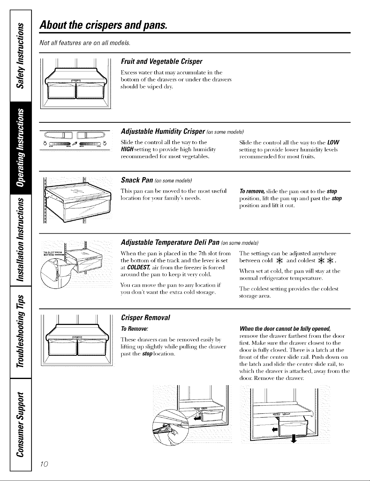
Aboutthe crispersandpans.
Not all features are on all models.
Fruit and Vegetable Crisper
Excess water that ma_ accunmlate in the
bottom of the (h'awe_s or under the (h'awe_
should be wiped dry.
Adjustable Humidity Crisper (onsomemodels)
Slide the control all the way to the Slide the control all the wax to the LOW
HIGHsetting to proxide high humidit_ .settin,,-_ to proxide lower humidity, lex els
recommended fi)r most xegetables, recommended fi)r most fl'uits.
Snack Pan (on some models)
II II
This pan can be mo_ed to the most useflfl
location fin" )ore" fmnil)'s needs.
To remove, slide the pan out to the stop
position, lilt the pan u l) and past the stop
position and lift it out.
Adjustable Temperature Dell Pan (onsomemodels)
When the pan is placed in the 7th slot fl'om
the bottom of the track and the lever is set
at COLDEST, air fl'om the fl'eezer is torced
around the pan to kee I) it ve_ T cold.
You can move the pan to any location if
wm don't want the extra cold storage.
The settings can be a(!justed anywhere
between cold _ and coldest _k _.
X4]_en set at cold, the pan will stay at the
normal refl_igerator temperature.
The coldest setting provides the coldest
storage a i'ea.
Crisper Removal
To Remove:
These (h'awex_ can be removed easily 1)y
lifting up slightl)while pulling the drawer
past the stop location.
When the door cannot be fully opened,
i'eln(_x'e the drawer fi_rth est froln the door
first. Make sure the drawer closest to the
door is fifllv closed. There is a latch at the
fl'ont of the center slide rail. Push down on
the latch and slide the center slide rail, to
which the drawer is attached, a_;_)' fl'om the
dOOF ]_.elnove file dI'aWeI-
10

Aboutthe freezer, ge.com
Not all features are on all models.
E
Appearance and features may vary
Appearance may vary
ok
Freezer Shelves and Baskets
Depending on your model, your fl'eezer
may teature:
A deep fl/ll-width basket
A shalh_w flfll-width basket
0 A haltXwidth basket
Basket/Shelf Removal
To remove the deep full-width basket on
freezer drawer models:
00I)en the freezer drawer until it stops.
0 The fl'eezer basket rests on a fl'ame
inside the fl'eezer drawei: i,ifl the basket
up at the back.
0 Pull the basket out to the stop location.
it from the slides.
0 I Jft the basket uI) at the ti'oI,t to release
0 IJft the back Ul) and out of the slide.
O A fidl-width wire shelf
A shelf above the ice storage bin
Lift the fl'ont up and lift the entire
basket up and out of the drawei;
When replacin O the basket make sure that
the Mre tabs and wire hooks on the sides
of the basket go into the slots in the top
of the uI)per basket slides,
NOTE:_Mw'avsbe sure to flflly close this
basket. You will know it is billy closed when
you teel it "click" into place.
Appearance may vary
Appearance may vary
f--
Shelf
Toremove the deep full-width baskets on
freezer door models, the shallow full-width
basket and the full-width wire shelf."
Pull the basket/shelf out to the stop
location.
IJft the fl'ont uI) and oxer the stop
h)cation.
Toremove the shelf above the ice bin:
0 Pull the shelf straight out.
Lift the basket/shelf up and out.
11

Aboutthe automaticicemaker.
A newly installed refrigerator may take 12to 24 hours to begin making ice.
Automatic Icemaker (on some models)
The icemM_.er ',_ill produce seven cubes
IcernakeE
i!i! IIII ii ii ii;ii!i
Gie ,,'J
PowerLight eeer rm
per c_cle--appro_mately 100-130 cubes
in a 24-hour period, depending on fl'eezer
coIllp_l(_(/(e(([ teIllpel';ittlie, ('((()Ill
temperature, (l[lillbe(" of doe(" ope(lll(gs
and other use conditions.
water comlecfion is made to tile icemake(;
set tile power switch in tile 0 {Of[) posit.ion.
Tile icemaker power light will turn green
\'Vhen the refligerator has been comlected
Tile icemaker Mll fill Mth w:Jter when it
making ice cubes.
See below fi)r hos_ to access ice and re:lch
tile power switch.
If tile reflJgerator is operated betbre tile
when tile Keezer light switch is pressed ill
or when tile Keezer door is closed.
to the water supply, set the l)o_er switch to
tile I (On) position.
cools to IS°F (-10°C). A newly installed
reiiJgemtor may take 12 to 24 lloms to begin
Accessing Ice and Reaching
the Power Switch
You will hear a buzzing sotmd e:mh time
the icemaker fills with wate(:
Thro_ aw_} the fi(_t fe_ batches of ice to
alh)w the _ater line to clea_:
Be sm'e nothing interferes with tile s_eep
of the feeler am(.
\'\]len tile bin fills to tile level of tile feeler
aml, tile icemaker will stop producing
ice. It is n(mnal fi)r several cubes to be
joined togethe(;
If ice is not used fl'equenfly, okl ice cubes
will become cloudy, taste stale and shrink.
NOTE: Inhomes with/ower-than-average water
pressure,you mayhear the/2emakercycle multiple
tinTeswhenmaking onebatchof ice.
Toreach the power switch.
ii!_iiii!i_i_iii_iii__iil}fi_!_iiiiii!_!ii_iiiiI!ii_!
_i _i_i_ __i
72
Toroach the icemaker power switch, pull tile
shelf above tile ice bin straight out. Mwavs
be sure to replace tile shelf_
Toaccess ice, simply pull tile bin fi)rward.
Icemaker Accessory Kit
If your refligerator did not come ah'ead_
equil}ped with an automatic icemaker,
an icemaker accessor_ kit is a_ailable at
ext ('a ('()st,
To Use the Dispenser (on some models)
Tile water dispenser is located on tile left
wall inside the reii_igerator compartment.
Todispensewater:
Hold tile glass against tile recess.
0 Push tile water dispenser button.
Hold tile glass tmderneath tile
dispenser for 2-3 seconds after
releasing tile dispenser button.
_A'lteI" Inav continue to dispense
alter the button is released.
To access ice,
Check tile back of tile refl_igerator fi)r
tile spedfic icemaker kit needed fi)r
VO//I" model.
If nowaterisdispensedwhentherefn)emtorisfTst
installed,theremaybeairinthewaterlinesystem.
Pressthedispenserbuttonforat/east2minutesto
removetrappedal?fromthewaterfineandtoill/the
watersystem.Duringthisprocess,thedispenser
noisemaybeloudastheairispurgedfromthe
waterlinesystem.Toflushouti_npuritiesinthe
waterline,throwawaythef7st6glassfulsofwater
NOTE:Toavoidwaterdeposits,thedispenser
shouldbecleanedperiodicaflyby wipingwith a
cleancloth orsponge.

Careand cleaningoftherefrigerator, ge.cem
Cleaning the Outside
The doorhandles and trim.Clean with a cloth
(laml)ened with soapy water L)_' with a soft
cloth. Do not use wax on the door handles
and trim.
Keep the outside clean. Wipe Mth a clean
cloth lightly dampened Mth kitchen
apl)liance wax or mild liqtfid dish
detergent. D_' and polish with a clean,
soft cloth.
Donot w/_)etherefrigeratorwith asoileddish
clothorwet towel Thesemayleavea residue
that canerodethe paint Donot usescouring
pads,powderedcleaners,bleachorcleaners
containingbleachbecausetheseproductscan
scratchand weakenthe paintfinish.
Cleaning the Inside
The stainless steel panels and doorhandles.
Stainless steel (on some models) can be
cleaned with a commerdallv available
stainless steel cleane_: A si)ra}:on st;finless
steel cleaner works best.
Do not use appliance wax or polish
on the stainless steel.
Tohelp prevent odors, leave an open be× at
baking soda in the reti-igerator and ti'eezer
COlIll)_I I'[ll/eats.
Unplug the refrigerator before cleaning. If this
is not practical, wring excess moisture out
of sponge or cloth when cleaning arotmd
switches, lights or controls.
Lrse an appliance wax polish on the inside
sml'hce between the (loo_.
Use warn/ water and baking soda solution--
about a tablespoon (l 5 ml) of baking soda
to a quart (l liter) at water: This both cleans
and neutralizes odo_. Rinse and wipe (h_'.
After cleaning the door gaskets, apply a
thin layer of petrolemnjelly to the door
gaskets at the hinge side. This helps kee I)
the gaskets ti'om sticking and bending out
of shape.
Avoidcleaningcud glassshe/yeswith hot water
becausetheextremetemperaturedifferencemay
causethemtobreak Handleglassshelves
carefu//gBumpingtemperedg/asscancause
it to shatter
Donot washanyplastic refrigeratorpartsin
thedishwasher
13

Careand cleaning of the refrigerator.
Behind the Refrigerator
Be caretul when moving the refl_igerator
away fl'om the wall. _M1types of floor
coverings can be (lamaged, particulady
cushioned coverings and those with
ei//bossed S/lI]_lces.
Pull the reti_igerator straight out and return
it m position by pushing it straight in.
Moving the refl_igerator in a side direction
may result in damage to the floor covering
or refl_igerato_:
Preparing for Vacation
When pushing the refrlgeretor back, make sure
you don't rofl over the power cord or icemaker
supply line (on some models).
For long \;l(-ations or absen(-es_ i'elllOVe
food and m_plug the reli_igerato_: Move
the fl'eezer control to the 0 (off) position,
and clean the inmrior with a baking soda
solution _ffone tablespoon (l 5 ml) _ff
baking soda to one quart (l liter) of wam_;
i,eave the dom_ open,
Set the icemaker power switch to the 0 (off)
posidon and shut off the water supply to
the refl_igemtm;
Preparing to Move
Secm'e all loose items such as base grille,
shelves and drawe_s by taping them
secm'ely in place to prevent damage.
_]_en using a hand truck to move the
reti_igerato_; do not rest the fi'ont or back
ot the refi_igerator against the hand truck.
This could damage the refi_igeratm: Handle
only fi'om the sides ot the refi_igeratm:
If the temperature can drop below
fi'eezing, have a qualified servicer drain the
water supply systeln (Oil SOlne models) to
prevent serious propert}, dalnage due to
flooding.
Besuretherefrigeratorstaysin anupwht
positionduringmoving.
/4

Replacingthe lightbulbs, gecom
Turning the control to the 0 (off) position does not remove power to the light circuit.
Refrigerator Lights
Appearance may vary
-&CAUTION:L>tb,,/bsmayboho,
0 Unplug tile ret/-igerato_:
Tile bulbs are located at tile top of the
refi'igerator compamnent behind tile
controls. To remove tile light shield,
grasp tile shield at tile back and pull
out to release tile tabs at tile back.
_]I Rotate tile shield do_n and then
for_ard to release tile tabs at tile fl'ont
of tile shield.
Freezer Light
P' CAUTION:L,_h,b.Ibsmayb_ho_
Unph:lg tile refi_igerator.
@ Tile bulb is located at tile top of tile
fl'eezer inside a light shield. To remove
the shield, grasp the shield at the back
and pull out to release tile tabs at tile
back.
0 _Jter replacing with an appliance bulb
ot tile SaI//e of lowel" wattage, , I'ei)]ace
tile shield.
0 Plug tile refligerator back in.
0 _Mter replacing with an appliance bulb
oI tile same or lower wattage, replace
tile shield.
0 Plug tile refl_igerator back in.
_]_ Rotate tile shield down and then
forward to release tile tabs at tile fl'ont
of the shield,
15
Installation
Refrigerator
Instructions
I Questions? Call 800.GE.CARES (800.432.2737) or Visit our Website at: ge.com
BEFORE YOU BEGIN
Read these instructions completely
and carefully.
• IMPORTANT - Savethese
instructions for local inspector's use.
• IMPORTANT - Observeall
governing codes and ordinances.
• Note to Installer - Be sure to leave these
instructions with the Consumer.
• Note to Consumer - Keep these
instructions for future reference.
• Skill level - Installation of this appliance
requires basic mechanical skills.
• Completion time - Refrigerator Installation
• Proper installation is the responsibility of
the installer.
In Canada, call 1.800.361.3400 or Visit our Website at: www.geappliances.ca
PREPARATION (cont.)
WATER SUPPLY TO THE ICEMAKER AND
DISPENSER (ON SOME MODELS)
If the refrigerator has an icemaker, it will have
to be connected to a cold water line. AGE water
supply kit (containing tubing, shutoff valve,
fittings and instructions) is available at extra
cost from your dealer, by visiting our Website
at ge.com (in Canada at www.geappliances.ca)
or from Parts and Accessories, 800.626.2002 (In
Canada 1.888.261.3055).
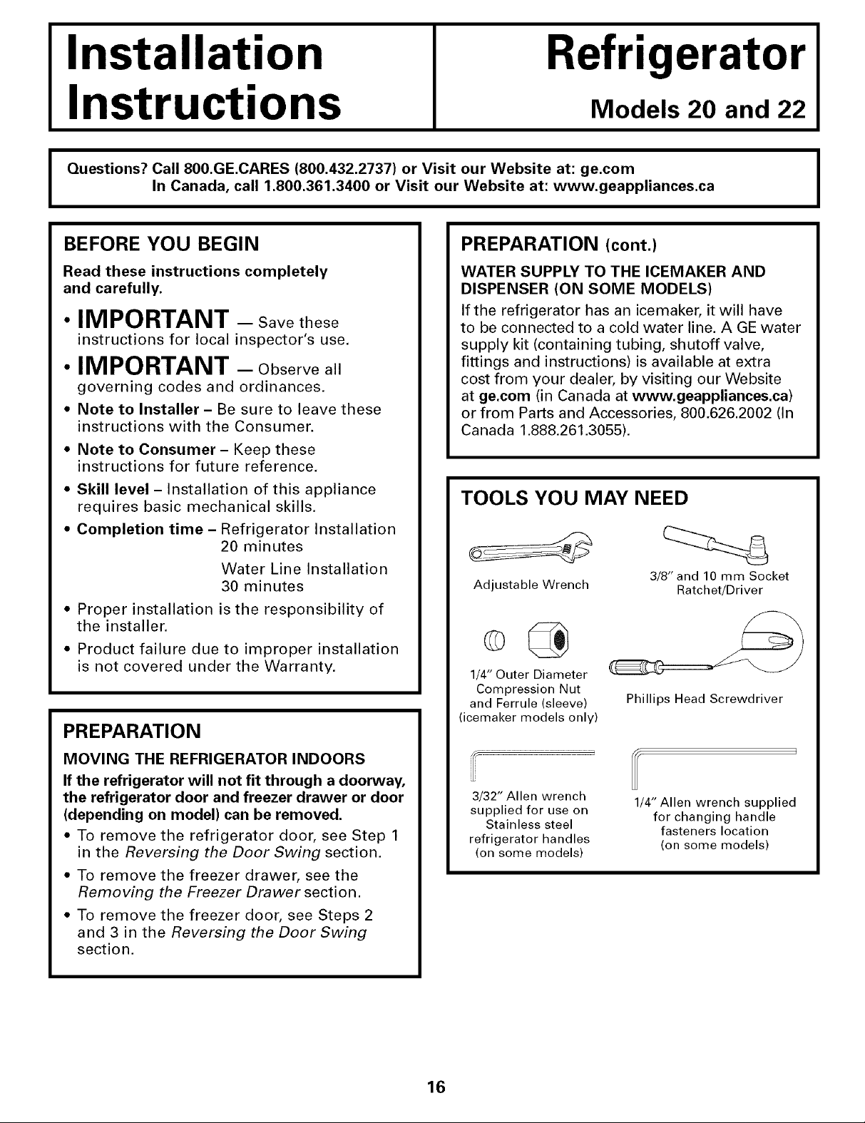
TOOLS YOU MAY NEED
20 minutes
Water Line Installation
30 minutes
Adjustable Wrench
Models 20 and 22
I
3/8" and 10 mm Socket
Ratchet/Driver
• Product failure due to improper installation
is not covered under the Warranty.
PREPARATION
MOVING THE REFRIGERATOR INDOORS
If the refrigerator will not fit through a doorway,
the refrigerator door and freezer drawer or door
(depending on model) can be removed.
• To remove the refrigerator door, see Step 1
in the Reversing the Door Swing section.
• To remove the freezer drawer, see the
Removing the Freezer Drawer section.
• To remove the freezer door, see Steps 2
and 3 in the Reversing the Door Swing
section.
1/4" Outer Diameter
Compression Nut
and Ferrule (sleeve)
(icemaker models only)
3/32" Allen wrench
supplied for use on
Stainless steel
refrigerator handles
(on some models)
Phillips Head Screwdriver
1/4" Allen wrench supplied
for changing handle
fasteners location
(on some models)
16
Installation Instructions
INSTALLING THE REFRIGERATOR
REFRIGERATOR LOCATION
• Do not install the refrigerator where the
temperature will go below 60°F (16°C) because it
will not run often enough to maintain proper
temperatures.
• Do not install the refrigerator where the
temperature will go above IO0°F (37°C) because it
will not perform properly.
• Install it on a floor strong enough to support it fully
loaded.
CLEARANCES
Allow the following clearances for ease of installation,
proper air circulation and plumbing and electrical
connections.
Sides 1/8" (4 mm)
Top 1" (25 mm)
Back 1" (25 mm)
REMOVE TOP CAP (onsomemodels)
* IMPORTANT NOTE: This refrigerator is34-1/2" deep.
Doors and passageways leading to the installation
location must be at least 36"wide in order to
leave the doors and handles attached to the
refrigerator while transporting it into the installation
location. If passageways are lessthan 36", the
refrigerator doors and handles can easily be scratched
and damaged. The top cap and doors can be removed
to allow the refrigerator to be safely moved indoors.
Start with Step A.
* If it is not necessary to remove doors, skip Step A.
Leave tape and all packaging on doors until the
refrigerator is in the final location.
*SKID REMOVAL: _lt refrigerator to each side to
remove skid.
* NOTE: Use a padded hand truck to move this
refrigerator. Place the refrigerator on the hand
truck with a side against the truck. We strongly
recommend that TWO PEOPLE move and complete
this installation.
[] Locate and remove the two Phillips head screws
on the top of the refrigerator. Remove the two
screws on each side at the rear of the top cap.
Lift off and remove top cap.
[] Remove the fresh-food door. Refer to Steps 1
through 3 of "Reversing the Door Swing" section.
[] Remove the bottom freezer drawer. Refer to
"Removing Freezer Drawer" section.
[] Move refrigerator to the installation location.
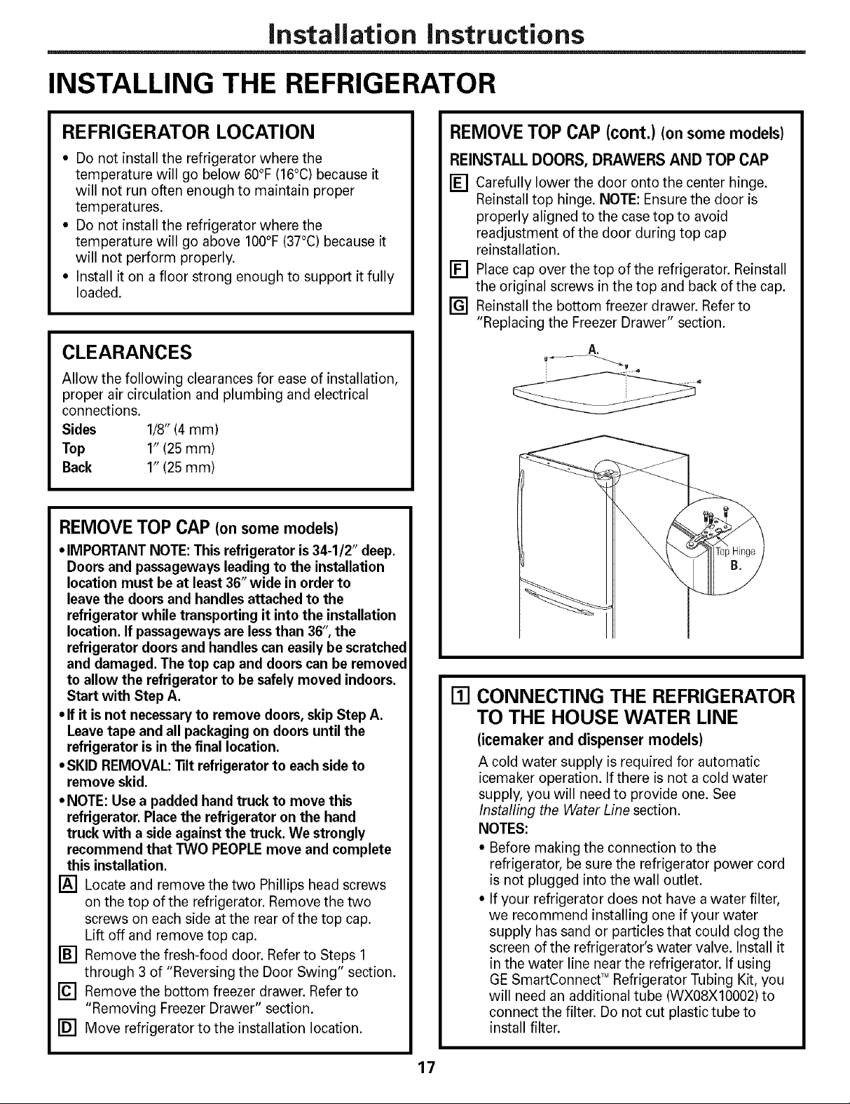
REMOVE TOP CAP (cont.) (onsomemodels)
REINSTALL DOORS, DRAWERS AND TOP CAP
[] Carefully lower the door onto the center hinge.
Reinstall top hinge. NOTE: Ensure the door is
properly aligned to the case top to avoid
readjustment of the door during top cap
reinstallation.
[] Place cap over the top of the refrigerator. Reinstall
the original screws in the top and back of the cap.
[] Reinstall the bottom freezer drawer. Refer to
"Replacing the Freezer Drawer" section.
A.
[] CONNECTING THE REFRIGERATOR
TO THE HOUSE WATER LINE
(icemaker and dispenser models)
A cold water supply is required for automatic
icemaker operation. If there is not a cold water
supply, you will need to provide one. See
Installing the Water Line section.
NOTES:
* Before making the connection to the
refrigerator, be sure the refrigerator power cord
is not plugged into the wall outlet.
* If your refrigerator does not have a water filter,
we recommend installing one if your water
supply has sand or particles that could clog the
screen of the refrigerator's water valve. Install it
in the water line near the refrigerator. If using
GE SmartConnect TM Refrigerator Tubing Kit, you
will need an additional tube (WXO8XIO002) to
connect the filter. Do not cut plastic tube to
install filter.
17

Installation Instructions
INSTALLING THE REFRIGERATOR (cont,)
[] CONNECTING THE REFRIGERATOR
TO THE HOUSE WATER LINE
(cont.)
[] If you are using copper tubing, place a
compression nut and ferrule (sleeve) onto
the end of the tubing coming from the
house cold water supply.
If you are using the GE SmartConnect TM
tubing, the nuts are already assembled to
the tubing.
[] If you are using copper tubing, insert
the end of the tubing into the refrigerator
connection, at the back of the refrigerator,
as far as possible. While holding the
tubing, tighten the fitting.
If you are using GE SmartConnect TM
tubing, insert the molded end of the
tubing into the refrigerator connection,
at the back of the refrigerator, and tighten
the compression nut until it is hand tight.
Then tighten one additional turn with a
wrench. Overtightening may cause leaks.
[] Fasten the tubing into the clamp provided
to hold it in position. You may need to pry
open the clamp.
[] TURN ON THE WATER SUPPLY
(icemaker and dispenser models)
Turn the water on at the shutoff valve
(house water supply) and check for
any leaks.
[] PLUG IN THE REFRIGERATOR
On models with an icemaker, before
plugging in the refrigerator, make sure
the icemaker power switch is set to the
O (off) position.
One of the illustrations below will look like
the connection on your refrigerator.
Icemaker-Ready models
1/4" -- Tubing
Copper Clamp
Tubing
1/4"
Compression
Nut
(sleeve)
SmartConnect T"
Tubing gerator
Icemaker-lnstalled Models
Refrigerator Ferrule
Connection
Connection
1/4" Tubing
See the grounding information attached
to the power cord.
[] PUT THE REFRIGERATOR
IN PLACE
Move the refrigerator to its final location.
18

Installation instructions
[] REMOVE THE FRESH FOOD
DOOR HANDLE
(For placement in the installation location or
reversal of the handles - on some models)
Stainless steel (on some models):
@ REMOVING
THE DOOR
HANDLE: Loosen
the set screws
with the 3/32"
Allen wrench
and remove
the handle. NOTE:
For Double Door
models follow the
same procedure
on the opposite
door.
O REVERSING THE
DOOR HANDLE:
•Remove the
handle mounting fasteners with a 1/4" Allen
wrench and transfer the handle mounting
fasteners to the right side.
• Remove and transfer the plug button and
logo badge to the left side of the fresh food
door. NOTE: Use a flat plastic edge to prevent
damaging the door. Remove any adhesive on
the door with a mild detergent. Remove the
paper covering on the adhesive backing on
the logo badge prior to carefully attaching the
badge to the door.
Plastic handle (on some models):
@ REMOVING
THE DOOR
HANDLE: Slide
the handle up
on the handle Badge
mounting
fasteners and
remove the
handle.
O REVERSING THE
DOOR HANDLE:
•Remove the
handle Button
mounting Mounting Fasteners
fasteners with a
3/8" or 10 mm (appearancemay vary)
socket wrench and transfer the handle
mounting fasteners to the right side.
•Remove and transfer the plug button and
logo badge to the left side of the fresh food
door. NOTE: Use a flat plastic edge to prevent
damaging the door. Remove any adhesive on
the door with a mild detergent. Remove the
paper covering on the adhesive backing on
the logo badge prior to carefully attaching the
badge to the door.
Mounting
Fasteners
(appearance may vary)
O_€'adge
lug
utton
of
After removing the handle: Move the small plug
button from the top right side of the door top and
insert it into the hole on the opposite side.
(appearance may vary)
[] REMOVE THE FREEZER DOOR
HANDLE
Stainless steel handle:
@ Loosen the set screws located on the underside
of the handle with the 3/32" Allen wrench and
remove the handle.
NOTE: If the handle mounting fasteners need to
be tightened or removed use a 1/4" Allen wrench.
Plastic handle:
@ Slide the handle to the right on the handle
mounting fasteners and remove the handle.
NOTE: If the handle mounting fasteners need to
be tightened or removed use a 3/8" or 10 mm
socket wrench.
Mounting
fasteners
(appearance may vary)
Slots on back
of handle
19

Installation Instructions
INSTALLING THE REFRIGERATOR (cont.)
[] ATTACH THE FRESH FOOD
DOOR HANDLE
Stainless steel handle:
Attach the handle
to the handle
mounting
fasteners and
tighten the set
screws with a
3/32" Allen
wrench. Mounting
NOTE: For Fasteners
Double Door
models follow the
same procedure Plug
on the opposite
door.
(appearance may vary)
Plastic handle:
O Attach the handle to the handle mounting
fasteners by aligning the slots with the handle
mounting fasteners.
0 Slide it down until it is firmly locked into
position.
[] ATTACH THE FREEZER DOOR
HANDLE
Stainless steel handle:
Q Attach the handle firmly to the mounting
fasteners and tighten the set screws on the
bottom of the handle with a 3/32" Allen wrench.
(appearance may vary)
Plastic handle:
Q Attach the handle to the mounting fasteners by
aligning the slots with the mounting fasteners.
O Slide it to the left until it is firmly locked into
position.
Mounting
fasteners
|J
Mounting
fasteners Slots on back of
(appearance may vary)
handle
20
Slots on back
(appearance may vary)
NOTE: A properly locked handle will be centered
on the freezer.
of handle
Installation Instructions
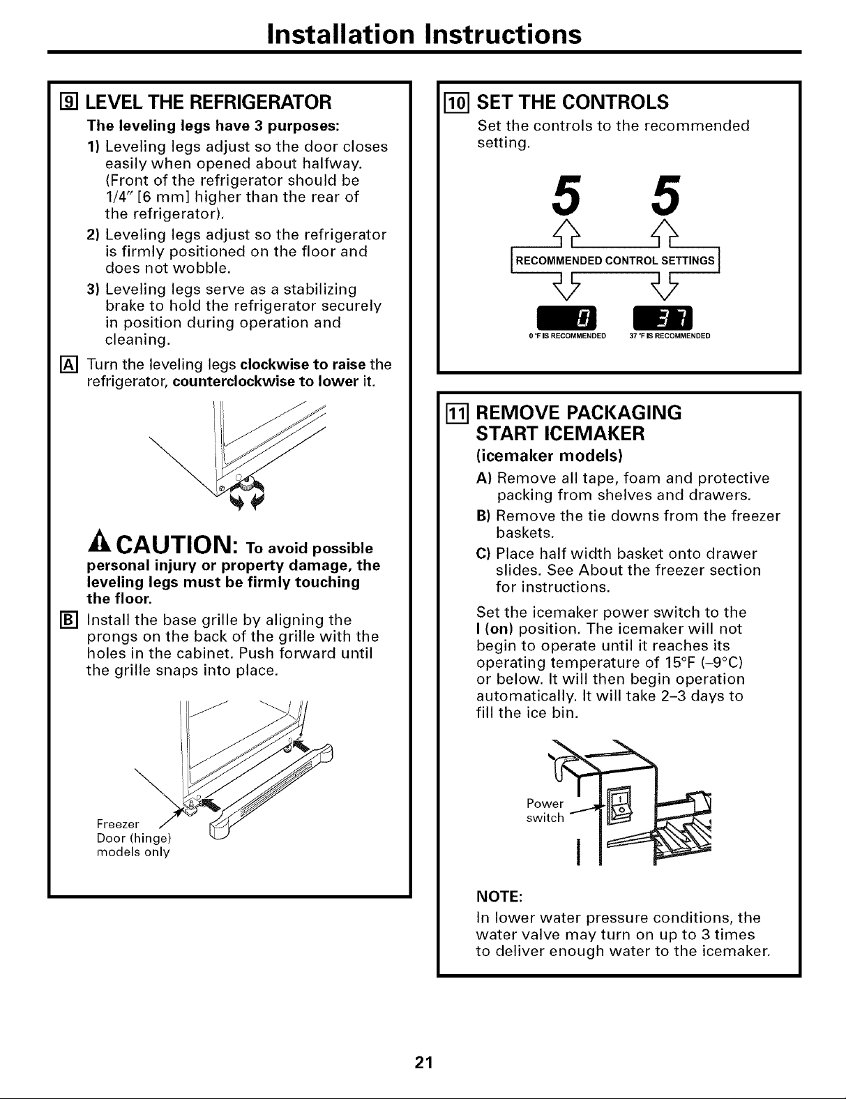
[] LEVEL THE REFRIGERATOR
The leveling legs have 3 purposes:
1) Leveling legs adjust so the door closes
easily when opened about halfway.
(Front of the refrigerator should be
1/4" [6 mm] higher than the rear of
the refrigerator).
2) Leveling legs adjust so the refrigerator
is firmly positioned on the floor and
does not wobble.
3) Leveling legs serve as a stabilizing
brake to hold the refrigerator securely
in position during operation and
cleaning.
[] Turn the leveling legs clockwise to raise the
refrigerator, counterclockwise to lower it.
CAUTION: Toavoidpossible
personal injury or property damage, the
leveling legs must be firmly touching
the floor.
[] Install the base grille by aligning the
prongs on the back of the grille with the
holes in the cabinet. Push forward until
the grille snaps into place.
[] SET THE CONTROLS
Set the controls to the recommended
setting.
5 5
[.EOOMME.OEOCO.T.OLS TT..OS]
0 "F IS RECOMMENDED 37 =F IS RECOMMENDED
REMOVE PACKAGING
[]
START ICEMAKER
(icemaker models)
A) Remove all tape, foam and protective
packing from shelves and drawers.
B) Remove the tie downs from the freezer
baskets.
C) Place half width basket onto drawer
slides. See About the freezer section
for instructions.
Set the icemaker power switch to the
I (on) position. The icemaker will not
begin to operate until it reaches its
operating temperature of 15°F (-9°C)
or below. It will then begin operation
automatically. It will take 2-3 days to
fill the ice bin.
\
Freezer J
Door (hinge)
models only
Pow
switch - I _"
NOTE:
In lower water pressure conditions, the
water valve may turn on up to 3 times
to deliver enough water to the icemaker.
21
Installation instructions
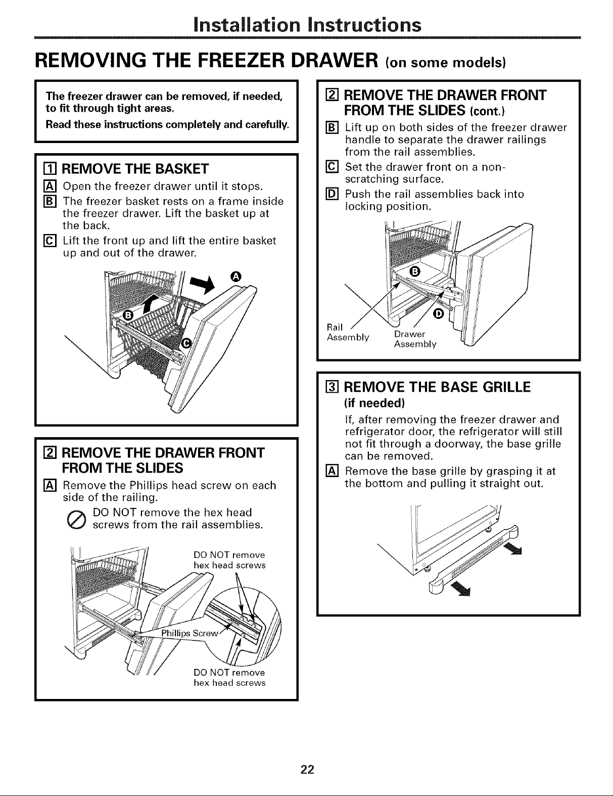
REMOVING THE FREEZER DRAWER (on some models)
The freezer drawer can be removed, if needed,
to fit through tight areas.
Read these instructions completely and carefully.
[] REMOVE THE BASKET
[] Open the freezer drawer until it stops,
[] The freezer basket rests on a frame inside
the freezer drawer. Lift the basket up at
the back.
[] Lift the front up and lift the entire basket
up and out of the drawer.
\
[] REMOVE THE DRAWER FRONT
FROM THE SLIDES
[] Remove the Phillips head screw on each
side of the railing.
[] REMOVE THE DRAWER FRONT
FROM THE SLIDES (cont.)
[] Lift up on both sides of the freezer drawer
handle to separate the drawer railings
from the rail assemblies.
[] Set the drawer front on a non-
scratching surface.
[] Push the rail assemblies back into
locking position.
Rail
Assembly Drawer
Assembly
[] REMOVE THE BASE GRILLE
(if needed)
If, after removing the freezer drawer and
refrigerator door, the refrigerator will still
not fit through a doorway, the base grille
can be removed.
[] Remove the base grille by grasping it at
the bottom and pulling it straight out.
Q DO NOT remove the hex head
screws from the rail assemblies,
DO NOT remove
hex head screws
DO NOT remove
hex head screws
22

Installation Instructions
REPLACING THE FREEZER DRAWER (on some models)
o Two people may be required to complete
I
[] ATTACH AND SECURE THE
[] Pull out the rail assemblies to the full
[] Locate the slots on the inside of the rail
this procedure.
DRAWER FRONT TO THE SLIDES
length on each side of the cabinet.
assemblies near the back.
Slot
[] ATTACH AND SECURE THE
I
DRAWER FRONT TO THE SLIDES
(cont.)
[] Replace the Phillips head screws on both
rail assemblies.
Phillips
Screw
[] REPLACE THE FREEZER BASKET
Replace the lower freezer basket by
lowering it into the frame.
Rail assembly
[] Insert the hooks at the back of the
drawer railings into the slots on the rail
assemblies.
[] Lower the front of the drawer, making
sure the tabs on the sides of the railings
fit into the front slots in the rail assemblies,
G
Slot
Tab
23

Installation instructions
REVERSING THE DOOR SWING (Single Door Refrigerator Models only)
IMPORTANT NOTES
When reversing the door swing:
NOTE: Door swing is not reversible on some
stainless steel models.
• Read the instructions all the way through
before starting.
• Handle parts carefully to avoid scratching
paint.
• Set screws down by their related parts to
avoid using them in the wrong places.
• Provide a non-scratching work surface for
the doors,
IMPORTANT: Once you begin, do not move
the cabinet until door-swing reversal is
completed.
These instructions are for changing the
hinges from the right side to the left side--if
you ever want to change the hinges back to
the right side, follow these same instructions
and reverse all references to left and right.
• Once door swing is finalized, ensure
the logo badge is properly aligned and
permanently secured to the door by
removing the adhesive cover on the back
side. NOTE: If necessary call Customer
Service for a replacement badge.
Unplug the refrigerator from its electrical
outlet.
Empty all door shelves, including the dairy
compartment.
[] REMOVE THE
REFRIGERATOR DOOR
[] Tape the door shut with masking tape.
[] Remove the hinge cover on top of the
refrigerator door by squeezing it and
pulling it up.
[] Using a 3/8" or 10 mm socket
ratchet/driver, remove the bolts securing
the top hinge to the cabinet. Then lift the
hinge straight up to free the hinge pin
from the socket in the top of the door.
O
Hinge Cover
__l II To_inge
TOOLS YOU WiLL NEED
Adjustable Wrench 3/8" and 10 mm Socket
Masking Tape Putty Knife or
Phillips Screwdriver
Ratchet!Driver
Thin-blade Screwdriver
[]
Remove the tape and tilt the door away
from the cabinet. Lift the door off the
center hinge pin. Ensure that the white
hinge pin thimble remains on the hinge pin
or inside door hinge pin hole located in the
bottom of the door.
[] Set the door on a non-scratching surface
with the inside up.
24
Installation instructions
[] REMOVE THE CENTER HINGE PIN
[] On models with a freezer door, tape the
door shut with masking tape.
[] Using an adjustable wrench, remove the
center hinge pin.
[]
REMOVE THE FREEZER DOOR
(freezer door models)
[]
Remove the tape and tilt the door away
from the cabinet. Lift the door off the
bottom hinge pin.
NOTE: There is a plastic washer between
the hinge and the top of the freezer door.
Do not lose.
[] TRANSFER BOTTOM HINGE
BRACKET (freezer door models)
[] Remove the base grille by grasping it at
the bottom and pulling it straight out.
[] Using a 3/8" or 10 mm socket
ratchet/driver, remove the screws
securing the bottom hinge bracket to the
cabinet.
[] Using an adjustable wrench, remove the
hinge pin and washer(s) from the right
side of the bracket and install on the left.
_'-_"_- J Washer(s)
[] Set the door on a non-scratching surface
with the inside up.
[] REMOVE CENTER HINGE
Using a 3/8" or 10 mm socket
ratchet/driver and Phillips head
screwdriver, remove the bolts and screws
securing the center hinge to the cabinet.
Set hinge, bolts, screws, washer (on
freezer door models) and hinge pin aside.
On models with a freezer drawer, skip to
Step 7.
25
Installation Instructions
REVERSING THE DOOR SWING (cont.)
[] TRANSFER BOTTOM HINGE
BRACKET (freezer door models, cont.)
[] Install the bottom hinge bracket on the
left side of the cabinet.
jjj
[] Replace the base grille by aligning the
prongs on the back of the grille with the
holes in the cabinet. Push forward until
the grille snaps into place,
[] INSTALL CENTER HINGE
[] Transfer the plug button and screws in
the hinge holes on the left side to the
right side.
[] Install the center hinge on the left side.
S
TRANSFER FREEZER DOOR STOP
[]
(freezer door models)
Remove the door stop on right side of the
[]
bottom of the freezer door by removing
the two screws.
Move the plastic hinge hole thimble to the
[]
opposite hole.
Install the door stop on the left side.
[]
Bottom of Freezer Door
(Right Side)
Bottom of Freezer Door
(Left Side)
[] HANG THE FREEZER DOOR
(freezer door models)
Lower the freezer door onto the bottom
hinge pin, then shut the door, making
sure to align the door with the cabinet.
Make sure the gasket on the door is flush
against the cabinet.
26

Installation instructions
[] INSTALL CENTER HINGE PIN
[] Install the center hinge pin.
NOTE: On models with a freezer door,
be sure to put the washer between the
top of the freezer door and the bottom
of the center hinge.
Freezer Door Models Freezer Drawer Models
TRANSFER REFRIGERATOR
@
DOOR STOP
[]
Remove the door stop on right side of
the bottom of the refrigerator door by
removing the two screws.
[]
Move the plastic hinge hole thimble to
the opposite hole.
[]
Install the door stop on the left side,
making sure to line up the screw holes
in the door stop with the holes in the
bottom of the door.
I-_ REHANG REFRIGERATOR DOOR
[] Lower the refrigerator door onto the
center hinge pin. Ensure that the white
hinge pin thimble is on the center hinge
pin or inside door hinge pin hole located
in the bottom of the door.
[]
Insert the top hinge pin into the hinge
hole on top of the refrigerator door. Make
sure the door is aligned with the cabinet.
Attach the hinge to the top of the cabinet
loosely with the bolts.
[]
Make sure the gasket on the door is
flush against the cabinet and is not
folded. Support the door on the handle
side and make sure the door is straight
and the gap between the doors is even
across the front. While holding the door
in place, tighten the top hinge bolts.
Replace the hinge cover.
Bottom of Bottom of
Refrigerator Door Refrigerator Door
(Right Side) (Left Side)
[] TRANSFER REFRIGERATOR
DOOR HANDLE TO RIGHT
Refer to Remove the Fresh Food Door
Handle and Attach the Fresh Food Door
Handle sections for instructions.
27

Installation Instructions
REMOVING THE DOORS (Double Door Refrigerator Models only)
IMPORTANT NOTES
NOTE: Door swing is not reversible.
• Read the instructions all the way through
before starting.
• Handle parts carefully to avoid scratching
paint.
• Set screws down by their related parts to
avoid using them in the wrong places.
• Provide a non-scratching work surface for
the doors,
IMPORTANT: Once you begin, do not move
the cabinet.
These instructions are for removing the
doors.
Unplug the refrigerator from its electrical
outlet.
Empty all door shelves, including the dairy
compartment.
TOOLS YOU WiLL NEED
Adjustable Wrench 3/8" and 10 mm Socket
Ratchet!Driver
[] REMOVE THE
REFRIGERATOR DOORS
[] Tape the doors shut with masking tape.
[] Remove the screw securing each hinge
cover, lift the hinge cover and place to
the side on top of the refrigerator.
Carefully disconnect the wire connector
and remove the screw securing the
ground wire.
Wire Hinge Cover
Connector
(appearance may vary)
[] Using a 3/8" or 10 mm socket
ratchet/driver, remove the bolts securing
the top hinge to the cabinet. Then lift the
hinge straight up to free the hinge pin
from the hinge pin hole in the top of the
door. Carefully remove the wires from the
hinge pin through the slot.
Masking Tape Putty Knife or
Thin-blade Screwdriver
Phillips Screwdriver
PARTS INCLUDED
C Spacer (on some models)
Hing __Pa_ge ay vary)
[] Remove the tape and tilt the door away
from the cabinet. Lift the door off the
center hinge pin. Ensure that the white
hinge pin thimble remains on the center
hinge pin or inside door hinge pin hole
located in the bottom of the door.
[] Set the door on a non-scratching surface
with the inside up.
28

Installation instructions
[] REMOVE CENTER HINGE
Using a 3/8" or 10 mm socket
ratchet/driver and Phillips head
screwdriver, remove the bolts and screw
securing the center hinge to the cabinet.
Set hinge, bolts, and screw aside.
[] REMOVE OPPOSITE DOOR
Follow the same procedure on the
opposite door.
[] REMOVE FREEZER DRAWER
Refer to the Removing the Freezer Drawer
section for instructions.
29

Installation instructions
REPLACING THE DOORS (Double Door Refrigerator Models only)
[] INSTALL CENTER HINGE
Install the center hinge on each side.
REHANG REFRIGERATOR DOORS
[]
[]
Lower the refrigerator door onto the
center hinge pin. Ensure that the white
hinge pin thimble is on the center hinge
pin or inside door hinge pin hole located
in the bottom of the door.
Thimble
Hinge Pin __
[]
Securely tape the door shut with masking
tape or have a second person support
the door.
[]
Route wires through top hinge pin slot.
Insert the top hinge pin into the hinge hole
on top of the refrigerator door. Make sure
the door is aligned with the cabinet and
opposite door. Attach the hinge to the top
of the cabinet loosely with the bolts.
[]
REHANGREFRIGERATORDOORS(CONT.)
[]
Make sure the gasket on the door is
flush against the cabinet and is not folded.
Make sure the door is straight and the gap
between the doors is even across the front.
While holding the aligned door in place,
tighten the top hinge bolts. Replace the
hinge cover and screw.
Hinge Cover ------__/}
To0.,n0e o,ts
{appearance may_ :'_
[] REPLACE OPPOSITE DOOR
Follow the same procedure on the
opposite door.
[] ALIGN DOUBLE DOORS
If the top of the doors are uneven, first
try to raise the lowest door by turning the
leveling leg on the same side as the door
until the doors are even. If the unit rocks,
re-adjust the leveling legs to the extent
that the unit is stable.
• • • i
. p Hinge
Pin Pin Slot
(appearance may vary)
[] Reconnect the wire connector and
reconnect the ground wire using the screw
removed earlier. Ensure that the wire
connector is fully engaged.
IMPORTANT: The ground wire must be
reinstalled to ensure a proper ground.
Wire --------- __-_/_
till _
Coooe .
Ground Wire J_'_o__/j]_
If the doors remain uneven, use a C spacer
to align the doors. While lifting the door
on the hinge side with one hand, insert a
C spacer with pliers. Continue to add C
spacers until the doors are even.
Spacer
[] REPLACE FREEZER DRAWER
Refer to the Replacing the Freezer Drawer
section for instructions.
 Loading...