

Page 1
Panda™ and Giraffe™ Warmers
Service Manual
M1128921 Revision J
Class A
© 2007-2017 General Electric Company
All rights reserved.
Page 2

General Electric Company reserves the right to make changes in specifications and features shown herein, or discontinue the product
described at any time without notice or obligation. Contact your GE Representative for the most current information.
Trademarks
GE, the GE Monogram, Giraffe, and Panda are trademarks of General Electric Company.
All other third party trademarks are the property of their respective owner.
Page 3

Revision History
Revision Revision Date Revision Description
J May 2017
H July 2016 Implemented updates supporting LED display design change.
G March 2016
F October 2014
E June 2014 Added CFDA and new RoHS accessories.
D July 2013
C May 2013
B March 2013
A February 2013
005 September 2011 Implemented IEC 3rd edition compliance updates.
004 January 2010 Added language disclaimer.
003 December 2008 Implemented updates supporting software changes.
002 November 2007 Implemented graphic improvements and text changes.
001 October 2007 Initial release.
Updated part numbers, Masimo SPO
(Appendix A), and format of front and back covers.
Added sample UDI symbol and description, and scale checkout
and calibration procedures. Updated part numbers and names of
Panda and Giraffe Warmers.
Added printing specification to Service Manual bill of material
(BOM).
Updated Masimo SET product names and Wall Mount Warmer
installation instructions for fixed surfaces.
Updated enclosure dimension specifications and addressed
bumper installation for Wall Mount Warmers (Appendix E).
Corrected title of persons responsible for installing Wall Mount
Warmers.
Implemented updates supporting Freestanding and Wall Mount
Warmers.
cable accessories
2
RH-1
Page 4

RH-2 Service Manual
Page 5

Table of Contents
Table of Contents
About this Manual .............................................................................................................i
Scope and Intended Users ...........................................................................................................................................i
Conventions.........................................................................................................................................................................i
User Responsibility ...........................................................................................................................................................i
Important Safety Information.......................................................................................iii
Warnings, Cautions, and Notes............................................................................................................................... iv
Service Language Disclaimer.............................................................................................................................v
Symbols ............................................................................................................................................................................ xiii
Regulatory.......................................................................................................................................................................xiv
Standards................................................................................................................................................................. xiv
Chapter 1: Functional Description.............................................................................1-1
1.1 Introduction ..........................................................................................................................................................1-1
1.1.1 Mechanical Controls and Cable Connections ...........................................................................1-4
1.1.2 Controls and Displays...........................................................................................................................1-7
1.2 Mechanical Modules.........................................................................................................................................1-8
1.2.1 Heater Head Assembly ........................................................................................................................1-8
1.2.2 Rails...............................................................................................................................................................1-8
1.2.3 Optional Resuscitation Assembly (Bedded and Freestanding Only)...............................1-8
1.2.4 Probe Panel Assembly..........................................................................................................................1-8
1.2.5 Base Assembly (Bedded and Freestanding Only) ....................................................................1-8
1.2.6 Bed Assembly (Bedded Only).............................................................................................................1-9
1.2.7 Optional In-Bed Scale (Bedded Only).............................................................................................1-9
1.2.8 Optional SpO2 Module..........................................................................................................................1-9
1.2.9 Giraffe Shuttle Accessory (Bedded Only)......................................................................................1-9
1.3 System Functions............................................................................................................................................1-10
1.3.1 System Overview (Fully-Loaded Bedded Shown)..................................................................1-10
1.3.2 Hands Free Alarm Silence................................................................................................................1-11
1.3.3 Watchdog................................................................................................................................................1-11
1.3.4 Battery Management......................................................................................................................... 1-12
1.3.5 Power Fail................................................................................................................................................ 1-13
1.3.6 External Communication..................................................................................................................1-15
1.3.7 Service Mode.......................................................................................................................................... 1-16
1.3.8 Display.......................................................................................................................................................1-16
1.3.9 Touch Panel............................................................................................................................................1-16
1.3.10 Elevating Base (Bedded Models Only)......................................................................................1-17
1.3.11 Observation Lights.......................................................................................................
1.3.12 Procedure Light (Optional on Panda Warmer) ....................................................................1-18
1.3.13 Heat Control ........................................................................................................................................1-19
1.3.14 Scale (Bedded Models Only) .........................................................................................................1-23
.....................1-18
TOC-1
Page 6

1.3.15 SpO2........................................................................................................................................................1-23
1.3.16 Alarms.....................................................................................................................................................1-24
1.3.17 Equipment Grounding..................................................................................................................... 1-25
1.3.18 AC/DC Power Distribution .............................................................................................................1-26
1.4 RS-232 Serial Data..........................................................................................................................................1-27
1.4.1 RS-232 Connector ...............................................................................................................................1-27
1.4.2 Data Stream...........................................................................................................................................1-27
1.4.3 Nurse Call ................................................................................................................................................1-28
Chapter 2: Installation, Maintenance, and Checkout ............................................2-1
2.1 Warmer Maintenance Schedule.................................................................................................................2-1
2.1.1 Operator Maintenance.........................................................................................................................2-1
2.1.2 Service Maintenance.............................................................................................................................2-1
2.2 Installation and Service Checkout Procedures ....................................................................................2-2
2.2.1 Mechanical Checks................................................................................................................................2-2
2.2.2 Controller Checks (Figure E-2)...........................................................................................................2-3
2.2.3 Electrical Safety Tests...........................................................................................................................2-4
2.3 Mounting the Universal Adapter Plate.....................................................................................................2-5
2.4 Scale Checkout Procedures ..........................................................................................................................2-6
2.4.1 Visual Inspection.....................................................................................................................................2-6
2.4.2 Center Weight Check ............................................................................................................................2-6
2.4.3 Off Center Weight Check.....................................................................................................................2-6
2.4.4 Load Cell Check .......................................................................................................................................2-7
Chapter 3: Calibration .................................................................................................3-1
3.1 Scale Calibration (Bedded Models Only)..................................................................................................3-1
Chapter 4: Troubleshooting........................................................................................4-1
4.1 Service Mode........................................................................................................................................................4-1
4.1.1 Unit Information......................................................................................................................................4-1
4.1.2 Main Menu..................................................................................................................................................4-1
4.1.3 Unit Info Menu..........................................................................................................................................4-2
4.1.4 Operation Settings .................................................................................................................................4-3
4.1.5 Scale Calibration .....................................................................................................................................4-4
4.1.6 Date/Time...................................................................................................................................................4-5
4.1.7 Diagnostics ................................................................................................................................................4-6
4.1.8 Odometer Readings...............................................................................................................................4-9
4.1.9 Event Logs...............................................................................................................................................4-10
4.1.10 Set Defaults.............................................................................................................
4.1.11 Heat Engine Diagnostic.................................................................................................................. 4-13
4.2 PC Command Line Interface......................................................................................................................4-13
4.2.1 Accessing the PC Command Line Interface............................................................................ 4-13
.............................4-12
TOC-2 Service Manual
Page 7

4.2.2 PC Command Line Interface Main Menu..................................................................................4-14
4.2.3 PC Command Line Interface Sub-Menus..................................................................................4-15
4.2.4 Engineering Log Dump......................................................................................................................4-18
4.3 Troubleshooting Information.....................................................................................................................4-21
4.4 Troubleshooting Tables................................................................................................................................4-22
4.4.1 Lighting – Procedure Light...............................................................................................................4-22
4.4.2 Lighting – Observation Lights ........................................................................................................4-24
4.4.3 Display – LCD and Backlights......................................................................................................... 4-27
4.4.4 User Interface – Touch Panel.........................................................................................................4-29
4.4.5 System Failure – Sys Fail Message ..............................................................................................4-29
4.4.6 Alarms/Indicators................................................................................................................................4-35
4.4.7 Electronics – Patient Temperature Probe.................................................................................4-37
4.4.8 Electronics – Scale (Bedded Models Only)................................................................................4-38
4.4.9 Electronics – SpO2...............................................................................................................................4-39
4.4.10 Electronics – Elevating Base (Bedded Models Only).......................................................... 4-40
4.4.11 Electronics – Heat Control.............................................................................................................4-42
4.4.12 Electronics – Power Failure...........................................................................................................4-42
4.4.13 Mechanical (Bedded Models Only) ............................................................................................4-43
4.5 Troubleshooting Definitions and Acronyms.......................................................................................4-44
Chapter 5: Repair Procedures ....................................................................................5-1
5.1 Common Hand Tools........................................................................................................................................5-1
5.2 Heater Head Removal from Wall Bracket (Wall Mount Only)........................................................5-2
5.3 Heater Housing Repairs..................................................................................................................................5-2
5.3.1 Upper Heater Housing Removal......................................................................................................5-2
5.3.2 Heat Engine Assembly Removal (Figure 5-1 and Figure 5-5).............................................5-3
5.3.3 Heater Alignment Procedure.............................................................................................................5-5
5.3.4 Power Supply Replacement (Figure 5-1)......................................................................................5-8
5.3.5 Alarm Light Board Replacement (Figure 5-6 and Figure 5-8)............................................5-8
5.3.6 Replacing an Observation Light Bulb............................................................................................5-9
5.3.7 Replacing the Procedure Light Bulb............................................................................................5-10
5.4 Electronic Enclosure Repairs.................................................................................................................... 5-10
5.4.1 Power Board (Figure 5-6 and Figure 5-7)..................................................................................5-10
5.4.2 Control Board (Figure 5-6 and Figure 5-7
) ..............................................................................5-11
5.4.3 Lithium-Ion Battery Replacement (Figure 5-6 and Figure 5-7)......................................5-11
5.4.4 Touch Panel or LCD Assembly (Figure 5-7 and Figure 5-8)............................................. 5-12
5.4.5 Observation Light Dimmer Control (Figure 5-8)....................................................................5-13
5.4.6 Standby Switch Replacement (Figure 5-8).............................................................................. 5-13
5.4.7 Outlet Panel Repairs (Figure 5-9).................................................................................................. 5-14
5.4.8 F7 and F8 Fuse Replacement Instructions...............................................................................5-15
5.4.9 Maneuvering Handle..........................................................................................................................5-15
5.5 Probe Panel Housing Repairs.................................................................................................................... 5-16
5.5.1 Probe Panel Housing Disassembly (Figure 5-10 and Figure 5-11)................................5-16
5.5.2 SpO2 Interface Board Replacement (Figure 5-10 and Figure 5-11).............................5-16
Service Manual TOC-3
Page 8

5.5.3 SpO2 Connector/Flex Circuit Replacement (Figure 5-10 or Figure 5-11
as appropriate) ...............................................................................................................................................5-17
5.5.4 Scale Connector Replacement (Figure 5-10) (Bedded Models Only)............................ 5-18
5.5.5 Patient Probe Connector Replacement (Figure 5-10 or Figure 5-11
as appropriate) ...............................................................................................................................................5-18
5.5.6 Probe Panel Upper Housing Replacement ..............................................................................5-19
5.6 Appearance Strip Replacement...............................................................................................................5-20
5.7 Lower Unit Repairs (Bedded and Freestanding Models)...............................................................5-21
5.7.1 Removing the Bed (Figure 5-13) (Bedded Models Only).....................................................5-21
5.7.2 Elevating Column Replacement (Figure 5-14) (Bedded Models Only) .........................5-21
5.7.3 Foot Switches (Figure 5-14) (Bedded Models Only)..............................................................5-21
5.7.4 Caster Replacement (Figure 5-14) (Bedded and Freestanding Models).....................5-22
5.7.5 Adjusting Bed Height Using Manual Elevating Column (Bedded Model Only).........5-24
5.7.6 Base and Rail Mounting Block Replacement (Figure 5-14)
(Freestanding Models Only) ......................................................................................................................5-25
Chapter 6: Illustrated Parts ........................................................................................6-1
6.1 Heater Housing...................................................................................................................................................6-2
6.2 Electronics Enclosure .......................................................................................................................................6-4
6.3 Probe Panel Housing........................................................................................................................................6-8
6.3.1 Probe Panel Housing (with Masimo SET 1 SpO2 Jack)...........................................................6-8
6.3.2 Probe Panel Housing (with Masimo SET 2 or Nellcor SpO2 Jack).....................................6-9
6.4 Base Assembly (Bedded Models Only)................................................................................................... 6-10
6.4.1 Elevating Column Special Instructions ......................................................................................6-10
6.5 Bed Assembly (Bedded Models Only).....................................................................................................6-13
6.6 Storage Options (Bedded Models Only) ................................................................................................6-16
6.7 Freestanding Model Parts...........................................................................................................................6-18
6.8 Wall Mount Model Parts...............................................................................................................................6-19
6.8.1 FRU Wall Mount Warmer Bumper Kit (2063179-001) Content.......................................6-20
6.8.2 FRU Wall Mount Warmer Bracket Kit (Language-Specific) Content ............................6-20
6.9 Harness List .......................................................................................................................................................6-21
6.10 Options..............................................................................................................................................................6-22
6.10.1 Optional Equipment......................................................................................................................... 6-22
6.10.2 Replacement and Additional Parts...........................................................................................6-23
6.10.3 SpO2 Upgrade Kits ...........................................................................................................................6-24
6.10.4 Giraffe Scale Parts ............................................................................................................................6-26
6.10.5 Panda Scale Parts.............................................................................................................................6-26
6.10.6 Power Cords ........................................................................................................................................6-26
6.11 Labels.................................................................................................................................................................6-27
6.11.1 Labels on the Back of Giraffe Warmers or Panda iRes Warmers...............................6-27
6.11.2 Heater Grille Accessory Warning Label Set (Bedded Models)......................................6-28
6.11.3 Labels on Probe Panel Housing..................................................................................................6-29
TOC-4 Service Manual
Page 9

6.11.4 Control Panel Labels (Not Shown, See Figure 1-4).............................................................6-29
6.11.5 Labels on Freestanding Model.................................................................................................... 6-30
6.11.6 Labels on Wall Mount Model........................................................................................................6-32
6.12 Test Points........................................................................................................................................................6-36
6.12.1 Control Board......................................................................................................................................6-36
6.12.2 Power Board........................................................................................................................................6-37
6.13 Wiring Diagrams...........................................................................................................................................6-38
Appendix A: Specifications......................................................................................... A-1
A.1 Power Requirements and Accessory Outlets .......................................................................................A-1
A.2 Operating Environment...................................................................................................................................A-1
A.3 User Control Settings .......................................................................................................................................A-1
A.4 Performance ........................................................................................................................................................A-2
A.5 Mechanical Specifications.............................................................................................................................A-3
A.5.1 Bedded.........................................................................................................................................................A-3
A.5.2 Freestanding.............................................................................................................................................A-3
A.5.3 Wall Mount.................................................................................................................................................A-3
A.6 SpO2 Specifications..........................................................................................................................................A-4
A.6.1 Nellcor..........................................................................................................................................................A-4
A.6.2 Nellcor SpO2 Cables and Probes.....................................................................................................A-5
A.6.3 Power Fail Recovery..............................................................................................................................A-5
A.6.4 Masimo........................................................................................................................................................A-5
A.6.5 Masimo SpO2 Cables and Probes...................................................................................................A-7
A.6.6 Power Fail Recovery..............................................................................................................................A-7
Appendix B: Electromagnetic Compatibility............................................................B-1
B.1 Electromagnetic Compatibility (EMC) Guidance..................................................................................B-1
B.2 Manufacturer’s Guidance and Declaration Regarding Electronic Emissions........................B-1
B.3 Manufacturer’s Guidance and Declaration Regarding Electromagnetic Immunity...........B-2
B.4 International Electronic Commission (IEC) Guidance and Manufacturer’s
Declaration Regarding Electronic Immunity...............................................................................................B-3
B.5 Recommended Separation Distance between Portable and Mobile RF
Communications Equipment and the Warmer..........................................................................................B-4
Appendix C: Alarm Priorities...................................................................................... C-1
Appendix D: Troubleshooting ....................................................................................D-1
D.1 Service Mode (Application Software 1.0.9 and Earlier).................................................................... D-1
D.1.1 Unit-Specific Information ..................................................................................................................D-1
D.1.2 Operator Settings.................................................................................................................................. D-2
D.1.3 Calibration ................................................................................................................................................D-3
Service Manual TOC-5
Page 10

D.1.4 Diagnostics Using Serial Port........................................................................................................... D-3
D.1.5 File Capture.............................................................................................................................................. D-4
Appendix E: Installing Wall Mount Units ..................................................................E-1
E.1 Pre-Installation Preparation..........................................................................................................................E-2
E.2 Wall Mount Bracket Installation..................................................................................................................E-3
E.3 Bumper Installation (for Installations with Bassinets).......................................................................E-6
E.4 Heater Head Installation and Heater Alignment.................................................................................E-7
E.5 Mattress Height Label Installation (for Installations with Bassinets) ......................................E-10
E.6 Enclosure Dimensional Specification..................................................................................................... E-11
TOC-6 Service Manual
Page 11
About this Manual
Scope and Intended Users
This service manual describes how to maintain, repair, and service the Panda and Giraffe Warmers that are
used in hospital delivery rooms, hospital newborn nurseries and neonatal intensive care units (NICU).
The intended users for this manual are biomedical engineering service providers of the hospital and GE
Service personnel.
Conventions
This section introduces the various types of warnings, cautions, information notes, and symbols used in this
manual to alert you to possible safety hazards and to provide you with additional information.
Warning: A Warning statement is used when the possibility of injury to the patient or the
operator exists. (The warning icon is yellow.)
Caution: A Caution statement is used when the possibility of damage to the equipment exists.
SENSITIVE TO ELECTROSTATIC DISCHARGE CAUTION: An electrostatic discharge (ESD)
Susceptibility symbol is displayed to alert service personnel that the part(s) are sensitive to
electrostatic discharge and that static control procedures must be used to prevent damage to
the equipment.
Note: A Note provides additional information to clarify a point in the text.
Important: An Important statement is similar to a note, but is used for greater emphasis.
User Responsibility
This Product will perform in conformity with the description thereof contained in this manual and
accompanying labels and/or inserts, when assembled, operated, maintained and repaired in accordance
with the instructions provided. This Product must be checked periodically. A defective Product should not be
used. Parts that are broken, missing, plainly worn, distorted or contaminated should be replaced
immediately. Should such repair or replacement become necessary, GE Healthcare recommends that a
telephone or written request for service advice be made to the nearest GE Healthcare Regional Service
Center. This Product or any of its parts should not be repaired other than in accordance with written
instructions provided by GE Healthcare and by GE Healthcare trained personnel. The Product must not be
altered without GE Healthcare’s prior written approval. The user of this Product shall have the sole
responsibility for any malfunction that results from improper use, faulty maintenance, improper repair,
damage or alteration by anyone other than GE Healthcare.
i
Page 12

About this Manual
User Responsibility
ii Service Manual
Page 13

Important Safety Information
The service information is important for the safety of both the patient and operator and also serves to
enhance equipment reliability.
Warning: Before servicing the Giraffe and Panda Warmers, read through this entire
manual. As with all medical equipment, attempting to use this device without a
thorough understanding of its operation may result in patient or user injury. This
device should be serviced only by authorized service personnel. Additional
precautions specific to certain procedures are found in the text of this manual.
The information contained in this service manual pertains only to those models of products which are
marketed by GE Healthcare as of the effective date of this manual or the latest revision thereof. This service
manual was prepared for exclusive use by GE Healthcare service personnel in light of their training and
experience as well as the availability to them of parts, proper tools, and test equipment. Consequently,
GE Healthcare provides this service manual to its customers purely as a business convenience and for the
customer’s general information only without warranty of the results with respect to any application of such
information.
Furthermore, because of the wide variety of circumstances under which maintenance and repair activities
may be performed and the unique nature of each individual’s own experience, capacity, and qualifications,
the fact that a customer has received such information from GE Healthcare does not imply in any way that
GE Healthcare deems said individual to be qualified to perform any such maintenance or repair service.
Moreover, it should not be assumed that every acceptable test and safety procedure or method, precaution,
tool, equipment, or device is referred to within, or that abnormal or unusual circumstances may not warrant
or suggest different or additional procedures or requirements. This manual is subject to periodic review,
update, and revision. Customers are cautioned to obtain and consult the latest revision before undertaking
any service of the equipment.
Warning: The user or service staff should dispose of all the waste properly as per
federal, state, and local waste disposal regulations. Improper disposal could result
in personal injury and environmental impact.
Do not use malfunctioning equipment. If the system is under warranty, contact GE technical support at the
number on the back of the manual PRIOR to performing any repairs on the system.
iii
Page 14
Important Safety Information
Warnings, Cautions, and Notes
Warnings, Cautions, and Notes
Warning: Do not use the warmer in the presence of flammable anesthetics; an
explosion hazard exists under these conditions.
Warning: Thoroughly air dry the warmer after cleaning it with flammable agents.
Small amounts of flammable agents, such as ether, alcohol or similar cleaning
solvents left in the incubator can cause a fire.
Warning: Do not attempt to adjust the fixed base while a patient is in the bed. After
adjustments to the fixed base height have been made, ensure the fixed base is
locked in place before placing a patient in the bed.
Warning: Always connect the warmer directly to a hospital grade wall outlet.
Connecting to a power strip or another piece of equipment may result in shock
hazard.
Warning: Do not service, program or calibrate the warmer with the patient in the
bed.
Warning: Do not lean against side of warmer. Leaning against the side of the
warmer may cause it to tip over.
Warning: Bed-to-heater spacing less than approximately 85 cm will result in
incorrect operation and may adversely affect the patient’s condition.
Warning: This is a latex-free device. Latex is not to be used in the maintenance or
repair of this device.
Warning: The user or service staff should dispose all the waste properly as per
federal, state, and local waste disposal regulations. Improper disposal could result
in personal injury and environmental impact.
Warning: The heater head is 15 kg. Follow your local health and safety guidelines
for manual handling of heavy objects when lifting and carrying the heater head.
Caution: Servicing of this product in accordance with this service manual should
never be undertaken in the absence of proper tools, test equipment and the most
recent revision to this service manual which is clearly and thoroughly understood.
Caution: Always disconnect the power before performing service or maintenance
procedures detailed in this manual. Apply power only if you are specifically
instructed to do so as part of the procedure.
iv Service Manual
Page 15
Important Safety Information
For professional use only
Warnings, Cautions, and Notes
Caution: Technical competence required to service the warmers; the procedures
described in this service manual should be performed by trained and authorized
personnel only. Maintenance should only be undertaken by competent individuals
who have a general knowledge of and experience with devices of this nature. No
repairs should ever be undertaken or attempted by anyone not having such
qualifications. Genuine replacement parts manufactured or sold by GE Healthcare
must be used for all repairs. Read completely through each step in every procedure
before starting the procedure; any exceptions may result in a failure to properly and
safely complete the attempted procedure.
Caution: U.S. Federal law restricts this device to sale by, or on order of, a licensed
medical practitioner.
Caution: This device is for professional use only, by trained clinicians.
SENSITIVE TO ELECTROSTATIC DISCHARGE CAUTION: Use a static control work
station to ensure that static charges are safely conducted to ground and not
through static sensitive devices.
Note: Ranges listed in this supplement manual represent the operational ranges of the equipment. The
gauge ranges may exceed operational ranges.
Note: Air always means medical grade air.
Service Language Disclaimer
WARNING:
This service manual is available in English only.
(EN)
(BG)
• If a customer’s service provider requires a language other than English, it is the
customer’s responsibility to provide translation services.
• Do not attempt to service the equipment unless this service manual has been
consulted and is understood.
• Failure to heed this warning may result in injury to the service provider, operator, or
patient from electric shock, mechanical hazards, or other hazards.
ПРЕДУПРЕЖДЕНИЕ
Това упътване за работа е налично само на английски език.
• Ако доставчикът на услугата на клиента изиска друг език, задължение на клиента
е да осигури превод.
• Не използвайте оборудването, преди да сте се консултирали и разбрали
упътването за работа.
• Неспазването на това предупреждение може да доведе до нараняване на
доставчика на услугата, оператора или пациентa в резултат на токов удар,
механична или друга опасност.
Service Manual v
Page 16
Important Safety Information
Warnings, Cautions, and Notes
警告
本维修手册仅提供英文版本。
(ZH-CN)
警告
本服務手冊僅提供英文版本。
(ZH-HK)
警告
本維修手冊僅有英文版。
(ZH-TW)
• 如果客户的维修服务人员需要非英文版本,则客户需自行提供翻译服务。
• 未详细阅读和完全理解本维修手册之前,不得进行维修。
• 忽略本警告可能对维修服务人员、操作人员或患者造成电击、机械伤害或其他形
式的伤害。
• 倘若客戶的服務供應商需要英文以外之服務手冊,客戶有責任提供翻譯服務。
• 除非已參閱本服務手冊及明白其內容,否則切勿嘗試維修設備。
• 不遵從本警告或會令服務供應商、網絡供應商或病人受到觸電、機械性或其他的
危險。
• 若客戶的維修廠商需要英文版以外的語言,應由客戶自行提供翻譯服務。
• 請勿試圖維修本設備,除非 您已查閱並瞭解本維修手冊。
• 若未留意本警告,可能導致維修廠商、操作員或病患因觸電、機械或其他危險而
受傷。
(HR)
(CS)
(DA)
UPOZORENJE
Ovaj servisni priručnik dostupan je na engleskom jeziku.
• Ako davatelj usluge klijenta treba neki drugi jezik, klijent je dužan osigurati prijevod.
• Ne pokušavajte servisirati opremu ako niste u potpunosti pročitali i razumjeli ovaj
servisni priručnik.
• Zanemarite li ovo upozorenje, može doći do ozljede davatelja usluge, operatera ili
pacijenta uslijed strujnog udara, mehaničkih ili drugih rizika.
VÝSTRAHA
Tento provozní návod existuje pouze v anglickém jazyce.
•V případě, že externí služba zákazníkům potřebuje návod v jiném jazyce, je zajištění
překladu do odpovídajícího jazyka úkolem zákazníka.
• Nesnažte se o údržbu tohoto zařízení, aniž byste si přečetli tento provozní návod a
pochopili jeho obsah.
•V případě nedodržování této výstrahy může dojít k poranění pracovníka prodejního
servisu, obslužného personálu nebo pacientů vlivem elektrického proudu, respektive
vlivem mechanických či jiných rizik.
ADVARSEL
Denne servicemanual findes kun på engelsk.
• Hvis en kundes tekniker har brug for et andet sprog end engelsk, er det kundens
ansvar at sørge for oversættelse.
• Forsøg ikke at servicere udstyret uden at læse og forstå denne servicemanual.
• Manglende overholdelse af denne advarsel kan medføre skade på grund af elektrisk
stød, mekanisk eller anden fare for teknikeren, operatøren eller patienten.
vi Service Manual
Page 17
(NL)
(ET)
(FI)
Important Safety Information
Warnings, Cautions, and Notes
WAARSCHUWING
Deze onderhoudshandleiding is enkel in het Engels verkrijgbaar.
• Als het onderhoudspersoneel een andere taal vereist, dan is de klant
verantwoordelijk voor de vertaling ervan.
• Probeer de apparatuur niet te onderhouden alvorens deze onderhoudshandleiding
werd geraadpleegd en begrepen is.
• Indien deze waarschuwing niet wordt opgevolgd, zou het onderhoudspersoneel, de
operator of een patiënt gewond kunnen raken als gevolg van een elektrische schok,
mechanische of andere gevaren.
HOIATUS
See teenindusjuhend on saadaval ainult inglise keeles
• Kui klienditeeninduse osutaja nõuab juhendit inglise keelest erinevas keeles,
vastutab klient tõlketeenuse osutamise eest.
• Ärge üritage seadmeid teenindada enne eelnevalt käesoleva teenindusjuhendiga
tutvumist ja sellest aru saamist.
• Käesoleva hoiatuse eiramine võib põhjustada teenuseosutaja, operaatori või
patsiendi vigastamist elektrilöögi, mehaanilise või muu ohu tagajärjel.
VAROITUS
Tämä huolto-ohje on saatavilla vain englanniksi.
• Jos asiakkaan huoltohenkilöstö vaatii muuta kuin englanninkielistä materiaalia,
tarvittavan käännöksen hankkiminen on asiakkaan vastuulla.
• Älä yritä korjata laitteistoa ennen kuin olet varmasti lukenut ja ymmärtänyt tämän
huoltoohjeen.
• Mikäli tätä varoitusta ei noudateta, seurauksena voi olla huoltohenkilöstön,
laitteiston käyttäjän tai potilaan vahingoittuminen sähköiskun, mekaanisen vian tai
muun vaaratilanteen vuoksi.
(FR)
(DE)
ATTENTION
Ce manuel d’installation et de maintenance est disponible uniquement en anglais.
• Si le technicien d’un client a besoin de ce manuel dans une langue autre que
l’anglais, il incombe au client de le faire traduire.
• Ne pas tenter d’intervenir sur les équipements tant que ce manuel d’installation et de
maintenance n’a pas été consulté et compris.
• Le non-respect de cet avertissement peut entraîner chez le technicien, l’opérateur ou
le patient des blessures dues à des dangers électriques, mécaniques ou autres.
WARNUNG
Diese Serviceanleitung existiert nur in englischer Sprache.
• Falls ein fremder Kundendienst eine andere Sprache benötigt, ist es Aufgabe des
Kunden für eine entsprechende Übersetzung zu sorgen.
• Versuchen Sie nicht diese Anlage zu warten, ohne diese Serviceanleitung gelesen
und verstanden zu haben.
• Wird diese Warnung nicht beachtet, so kann es zu Verletzungen des
Kundendiensttechnikers, des Bedieners oder des Patienten durch Stromschläge,
mechanische oder sonstige Gefahren kommen.
Service Manual vii
Page 18
Important Safety Information
Warnings, Cautions, and Notes
ΠΡΟΕΙ∆ΟΠΟΙΗΣΗ
Το παρόν εγχειρίδιο σέρβις διατίθεται μόνο στα αγγλικά.
(EL)
FIGYELMEZTETÉS
Ezen karbantartási kézikönyv kizárólag angol nyelven érhető el.
(HU)
PERINGATAN
Panduan servis hanya tersedia dalam Bahasa Inggris.
(ID)
• Εάν ο τεχνικός σέρβις ενός πελάτη απαιτεί το παρόν εγχειρίδιο σε γλώσσα εκτός
των αγγλικών, αποτελεί ευθύνη του πελάτη να παρέχει τις υπηρεσίες μετάφρασης.
• Μην επιχειρήσετε την εκτέλεση εργασιών σέρβις στον εξοπλισμό αν δεν έχετε
συμβουλευτεί και κατανοήσει το παρόν εγχειρίδιο σέρβις
• Αν δεν προσέξετε την προειδοποίηση αυτή, ενδέχεται να προκληθεί τραυματισμός
στον τεχνικό σέρβις, στο χειριστή ή στον ασθενή από ηλεκτροπληξία, μηχανικούς ή
άλλους κινδύνους.
• Ha a vevő szolgáltatója angoltól eltérő nyelvre tart igényt, akkor a vevő felelőssége a
fordítás elkészíttetése.
• Ne próbálja elkezdeni használni a berendezést, amíg a karbantartási kézikönyvben
leírtakat nem értelmezték.
• Ezen figyelmeztetés figyelmen kívül hagyása a szolgáltató, működtető vagy a beteg
áramütés, mechanikai vagy egyéb veszélyhelyzet miatti sérülését eredményezheti.
• Apabila suatu penyedia layanan servis pelanggan memerlukan bahasa selain
Bahasa Inggris, merupakan tanggung jawab pelanggan untuk menyediakan layanan
penerjemahan.
• Jangan mencoba melakukan servis peralatan kecuali apabila telah membaca dan
memahami panduan servis ini.
• Tidak mengindahkan peringatan ini dapat menyebabkan cedera pada pemberi
layanan servis, operator, maupun pasien akibat sengatan listrik, bahaya mekanik,
maupun bahaya lain.
.
(IS)
(IT)
AÐVÖRUN
Þessi þjónustuhandbók er aðeins fáanleg á ensku.
• Ef að þjónustuveitandi viðskiptamanns þarfnast annas tungumáls en ensku, er það
skylda viðskiptamanns að skaffa tungumálaþjónustu.
• Reynið ekki að afgreiða tækið nema að þessi þjónustuhandbók hefur verið skoðuð og
skilin.
• Brot á sinna þessari aðvörun getur leitt til meiðsla á þjónustuveitanda, stjórnanda
eða sjúklings frá raflosti, vélrænu eða öðrum áhættum.
AVVERTENZA
Il presente manuale di manutenzione è disponibile soltanto in lingua inglese.
• Se un addetto alla manutenzione richiede il manuale in una lingua diversa, il cliente è
tenuto a provvedere direttamente alla traduzione.
• Procedere alla manutenzione dell’apparecchiatura solo dopo aver consultato il
presente manuale ed averne compreso il contenuto.
• Il mancato rispetto della presente avvertenza potrebbe causare lesioni all’addetto
alla manutenzione, all’operatore o ai pazienti provocate da scosse elettriche, urti
meccanici o altri rischi.
viii Service Manual
Page 19

(JA)
(KO)
(LV)
Important Safety Information
Warnings, Cautions, and Notes
警告
このサービスマニュアルには英語版しかありません。
• サービスを担当される業者が英語以外の言語を要求される場合、翻訳作業はそ
の業者の責任で行うものとさせていただきます。
• このサービスマニュアルを熟読し理解せずに、装置のサービスを行わないでく
ださい。
• この警告に従わない場合、サービスを担当される方、操作員あるいは患者 さん
が、感電や機械的又はその他の危険により負傷する可能性があります。
경고
본 서비스 매뉴얼은 영어로만 이용하실 수 있습니다 .
• 고객의 서비스 제공자가 영어 이외의 언어를 요구할 경우 , 번역 서비스를 제공하
는 것은 고객의 책임입니다 .
• 본 서비스 매뉴얼을 참조하여 숙지하지 않은 이상 해당 장비를 수리하려고 시도
하지 마십시오 .
• 본 경고 사항에 유의하지 않으면 전기 쇼크 , 기계적 위험 , 또는 기타 위험으로 인
해 서비스 제공자 , 사용자 또는 환자에게 부상을 입힐 수 있습니다 .
BRĪDINĀJUMS
Šī apkopes rokasgrāmata ir pieejama tikai angļu valodā.
• Ja klienta apkopes sniedzējam nepieciešama informācija citā valodā, klienta
pienākums ir nodrošināt tulkojumu.
• Neveiciet aprīkojuma apkopi bez apkopes rokasgrāmatas izlasīšanas un saprašanas.
•Šī brīdinājuma neievērošanas rezultātā var rasties elektriskās strāvas trieciena,
mehānisku vai citu faktoru izraisītu traumu risks apkopes sniedzējam, operatoram
vai pacientam.
(LT)
(NO)
ĮSPĖJIMAS
Šis eksploatavimo vadovas yra tik anglų kalba.
• Jei kliento paslaugų tiekėjas reikalauja vadovo kita kalba – ne anglų, suteikti vertimo
paslaugas privalo klientas.
•Nemėginkite atlikti įrangos techninės priežiūros, jei neperskaitėte ar nesupratote šio
eksploatavimo vadovo.
• Jei nepaisysite šio įspėjimo, galimi paslaugų tiekėjo, operatoriaus ar paciento
sužalojimai dėl elektros šoko, mechaninių ar kitų pavojų.
ADVARSEL
Denne servicehåndboken finnes bare på engelsk.
• Hvis kundens serviceleverandør har bruk for et annet språk, er det kundens ansvar å
sørge for oversettelse.
• Ikke forsøk å reparere utstyret uten at denne servicehåndboken er lest og forstått.
• Manglende hensyn til denne advarselen kan føre til at serviceleverandøren,
operatøren eller pasienten skades på grunn av elektrisk støt, mekaniske eller andre
farer.
Service Manual ix
Page 20
Important Safety Information
Warnings, Cautions, and Notes
OSTRZEŻENIE
Niniejszy podręcznik serwisowy dostępny jest jedynie w języku angielskim.
(PL)
AVISO
Este manual de assistência técnica encontra-se disponível unicamente em inglês.
(PT-BR)
ATENÇÃO
Este manual de assistência técnica só se encontra disponível em inglês.
(PT-PT)
•Jeśli serwisant klienta wymaga języka innego niż angielski, zapewnienie usługi
tłumaczenia jest obowiązkiem klienta.
•Nie próbować serwisować urządzenia bez zapoznania się z niniejszym
podręcznikiem serwisowym i zrozumienia go.
• Niezastosowanie się do tego ostrzeżenia może doprowadzić do obrażeń serwisanta,
operatora lub pacjenta w wyniku porażenia prądem elektrycznym, zagrożenia
mechanicznego bądź innego.
• Se outro serviço de assistência técnica solicitar a tradução deste manual, caberá ao
cliente fornecer os serviços de tradução.
• Não tente reparar o equipamento sem ter consultado e compreendido este manual
de assistência técnica.
• A não observância deste aviso pode ocasionar ferimentos no técnico, operador ou
paciente decorrentes de choques elétricos, mecânicos ou outros.
• Se qualquer outro serviço de assistência técnica solicitar este manual noutro idioma,
é da responsabilidade do cliente fornecer os serviços de tradução.
• Não tente reparar o equipamento sem ter consultado e compreendido este manual
de assistência técnica.
• O não cumprimento deste aviso pode colocar em perigo a segurança do técnico, do
operador ou do paciente devido a choques eléctricos, mecânicos ou outros.
(RO)
(RU)
ATENŢIE
Acest manual de service este disponibil doar în limba engleză.
•Dacă un furnizor de servicii pentru clienţi necesită o altă limbă decât cea engleză,
este de datoria clientului să furnizeze o traducere.
•Nu încercaţi să reparaţi echipamentul decât ulterior consultării şi înţelegerii acestui
manual de service.
• Ignorarea acestui avertisment ar putea duce la rănirea depanatorului, operatorului
sau pacientului în urma pericolelor de electrocutare, mecanice sau de altă natură.
ОСТОРОЖНО!
Данное руководство по техническому обслуживанию представлено только на английском
языке.
• Если сервисному персоналу клиента необходимо руководство не на английском,
а на каком-то другом языке, клиенту следует самостоятельно обеспечить
перевод.
• Перед техническим обслуживанием оборудования обязательно обратитесь к
данному руководству и поймите изложенные в нем сведения.
• Несоблюдение требований данного предупреждения
специалист по техобслуживанию, оператор или пациент получит удар
электрическим током, механическую травму или другое повреждение.
может привести к тому, что
x Service Manual
Page 21

(SR)
(SK)
(ES)
Important Safety Information
Warnings, Cautions, and Notes
UPOZORENJE
Ovo servisno uputstvo je dostupno samo na engleskom jeziku.
• Ako klijentov serviser zahteva neki drugi jezik, klijent je dužan da obezbedi
prevodilačke usluge.
• Ne pokušavajte da opravite uređaj ako niste pročitali i razumeli ovo servisno
uputstvo.
• Zanemarivanje ovog upozorenja može dovesti do povređivanja servisera, rukovaoca
ili pacijenta usled strujnog udara ili mehaničkih i drugih opasnosti.
UPOZORNENIE
Tento návod na obsluhu je k dispozícii len v angličtine.
• Ak zákazníkov poskytovateľ služieb vyžaduje iný jazyk ako angličtinu, poskytnutie
prekladateľských služieb je zodpovednosťou zákazníka.
• Nepokúšajte sa o obsluhu zariadenia, kým si neprečítate návod na obluhu a
neporozumiete mu.
• Zanedbanie tohto upozornenia môže spôsobiť zranenie poskytovateľa služieb,
obsluhujúcej osoby alebo pacienta elektrickým prúdom, mechanické alebo iné
ohrozenie.
ATENCION
Este manual de servicio sólo existe en inglés.
• Si el encargado de mantenimiento de un cliente necesita un idioma que no sea el
inglés, el cliente deberá encargarse de la traducción del manual.
• No se deberá dar servicio técnico al equipo, sin haber consultado y comprendido
este manual de servicio.
• La no observancia del presente aviso puede dar lugar a que el proveedor de
servicios, el operador o el paciente sufran lesiones provocadas por causas eléctricas,
mecánicas o de otra naturaleza.
(SV)
(SL)
VARNING
Den här servicehandboken finns bara tillgänglig på engelska.
• Om en kunds servicetekniker har behov av ett annat språk än engelska, ansvarar
kunden för att tillhandahålla översättningstjänster.
• Försök inte utföra service på utrustningen om du inte har läst och förstår den här
servicehandboken.
• Om du inte tar hänsyn till den här varningen kan det resultera i skador på
serviceteknikern, operatören eller patienten till följd av elektriska stötar, mekaniska
faror eller andra faror.
OPOZORILO
Ta servisni priročnik je na voljo samo v angleškem jeziku.
• Če ponudnik storitve stranke potrebuje priročnik v drugem jeziku, mora stranka
zagotoviti prevod.
• Ne poskušajte servisirati opreme, če tega priročnika niste v celoti prebrali in razumeli.
• Če tega opozorila ne upoštevate, se lahko zaradi električnega udara, mehanskih ali
drugih nevarnosti poškoduje ponudnik storitev, operater ali bolnik.
Service Manual xi
Page 22

Important Safety Information
Warnings, Cautions, and Notes
DİKKAT
Bu servis kılavuzunun sadece ingilizcesi mevcuttur.
(TR)
ЕСКЕРТУ
Осы қызмет көрсету нұсқаулығы тек ағылшын тілінде қолжетімді.
(KK)
CẢNH BÁO
Hướng dẫn sử dụng dịch vụ này chỉ sẵn dùng bằng tiếng Anh.
(VI)
•Eğer müşteri teknisyeni bu kılavuzu ingilizce dışında bir başka lisandan talep ederse,
bunu tercüme ettirmek müşteriye düşer.
•Servis kılavuzunu okuyup anlamadan ekipmanlara müdahale etmeyiniz.
•Bu uyarıya uyulmaması, elektrik, mekanik veya diğer tehlikelerden dolayı teknisyen,
operatör veya hastanın yaralanmasına yol açabilir.
• Егер тұтынушылардың қызметтер жеткізушісі ағылшын тілінен басқа тілді
талап етсе, аудару қызметтерімен қамтамасыз ету тұтынушының
жауапкершілігіне кіреді.
• Осы қызмет көрсету нұсқаулығын түсініп, ол туралы кеңес алмайынша
жабдыққа қызмет көрсетуге тырыспаңыз.
• Осы ескертуді орындамау электр тогының соғуы, механикалық немесе
басқа да қауіптер
немесе емделушінің жарақаттануына алып келуі мүмкін.
• Nếu nhà cung cấp dịch vụ của khách hàng yêu cầu ngôn ngữ khác ngoài tiếng
Anh, thì khách hàng phải có trách nhiệm cung cấp các dịch vụ dịch thuật.
• Không được tìm cách sửa chữa thiết bị trừ khi đã tham khảo và hiểu rõ Hướng
dẫn sử dụng dịch vụ này.
• Bỏ qua lời cảnh báo này có thể gây thương tích cho nhà cung cấp d
viên vận hành hoặc bệnh nhân do sốc điện, những nguy hiểm về máy móc hoặc
yếu tố khác.
салдарынан қызметтер жеткізушісінің, оператордың
ịch vụ, nhân
xii Service Manual
Page 23
Symbols
Important Safety Information
Symbols
This section identifies the symbols that are displayed on the Panda and Giraffe Warmers:
Symbol Description
Type B Equipment
Functional Earth Terminal
Protection Earth Terminal
Alternating Current
Alarm Silence
European Union Representative
Consult accompanying documents.
UDI
Catalog Number
Serial Number
Unique Service Identifier. The UDI is a unique marking for identification of the medical
device.
Manufacturer
Do not reuse
Help menu
Patient temperature
Observation light
Scale
Date of manufacture
Increase/decrease, up/down
Do not lean on the unit.
Do not place items in radiant heat path.
Service Manual xiii
Page 24
Important Safety Information
Regulatory
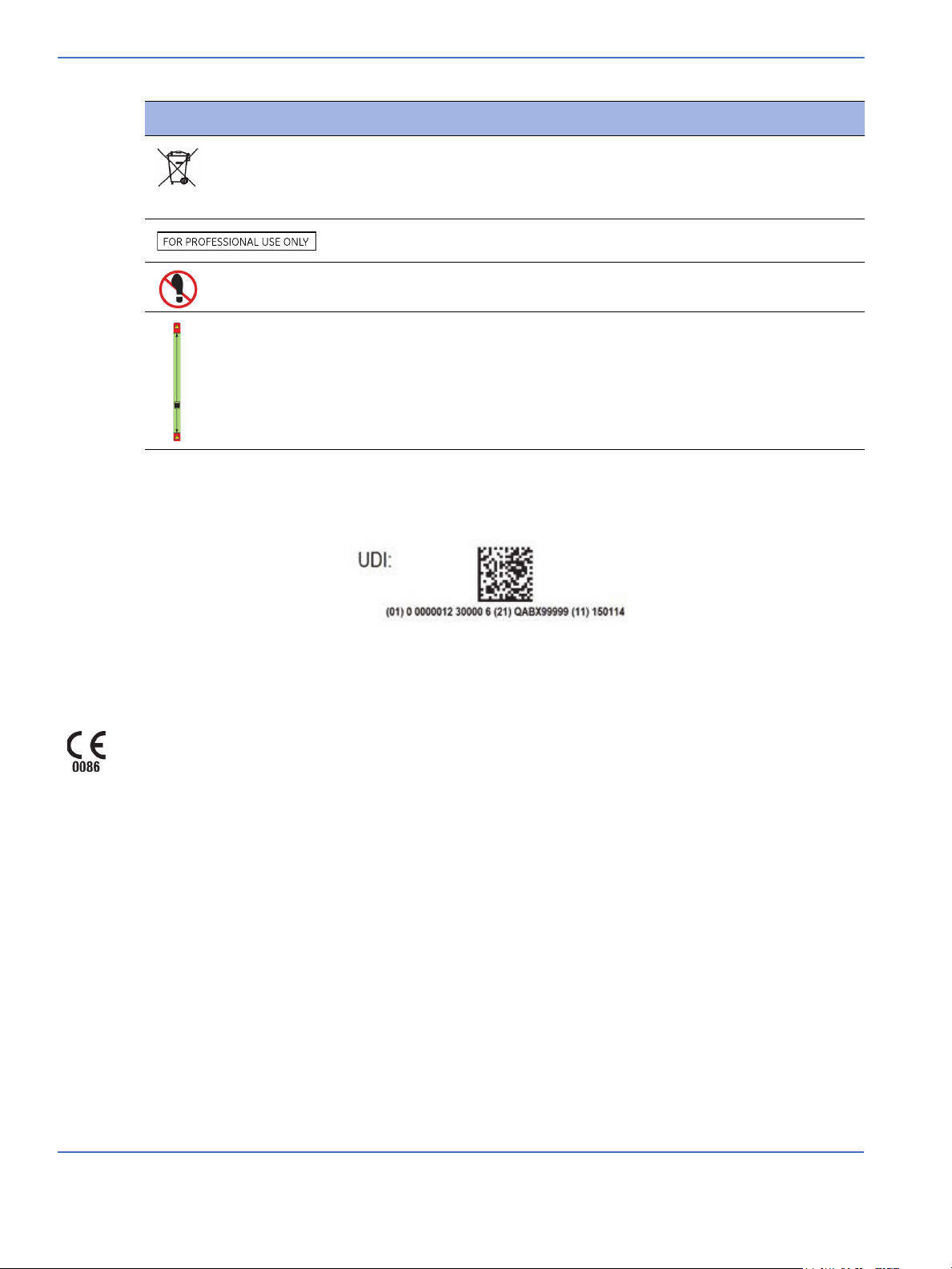
Symbol Description
Beginning in September 2016, some medical devices sold in the USA must be labeled with a Unique Device
Identifier (UDI). The UDI label will be located on or adjacent to the serial number label on the device.
Example of UDI label format:
This symbol indicates that the waste of electrical and electronic equipment
must not be disposed as an unsorted municipal waste and must be collected
separately. Please contact an authorized representative of the manufacturer
for information concerning the decommissioning of your equipment.
Equipment shall be used only by qualified, trained medical personnel.
Do not step or stand on surface.
Acceptable mattress height range.
Regulatory
GE Healthcare has declared that this product conforms with the European Council Directive 93/42/EEC
Medical Device Directive when it is used in accordance with the instructions provided in the Operation and
Maintenance Manual.
Standards
This device is designed to meet the requirements of:
• IEC 60601-2-21 with amendment
• IEC 60601-1 with amendment
• IEC 60601-1-2 with amendment
• UL 60601-1
• BSEN - 45501 with amendment
xiv Service Manual
Page 25
Chapter 1: Functional Description
1.1 Introduction
The GE Healthcare Panda and Giraffe Warmers are devices with a radiant heating source intended to
maintain the thermal balance of an infant patient by direct radiation of energy in the infrared region of the
electromagnetic spectrum.
Radiant heat from an infrared heat source is focused onto the bed to warm the patient. The operator may
select either the heater power (manual mode) or skin temperature (baby mode) control method. Depending
on the control method selected, the heater is either regulated at the operator selected power level or the
heater output is modulated to maintain the patient’s temperature at the value selected by the operator.
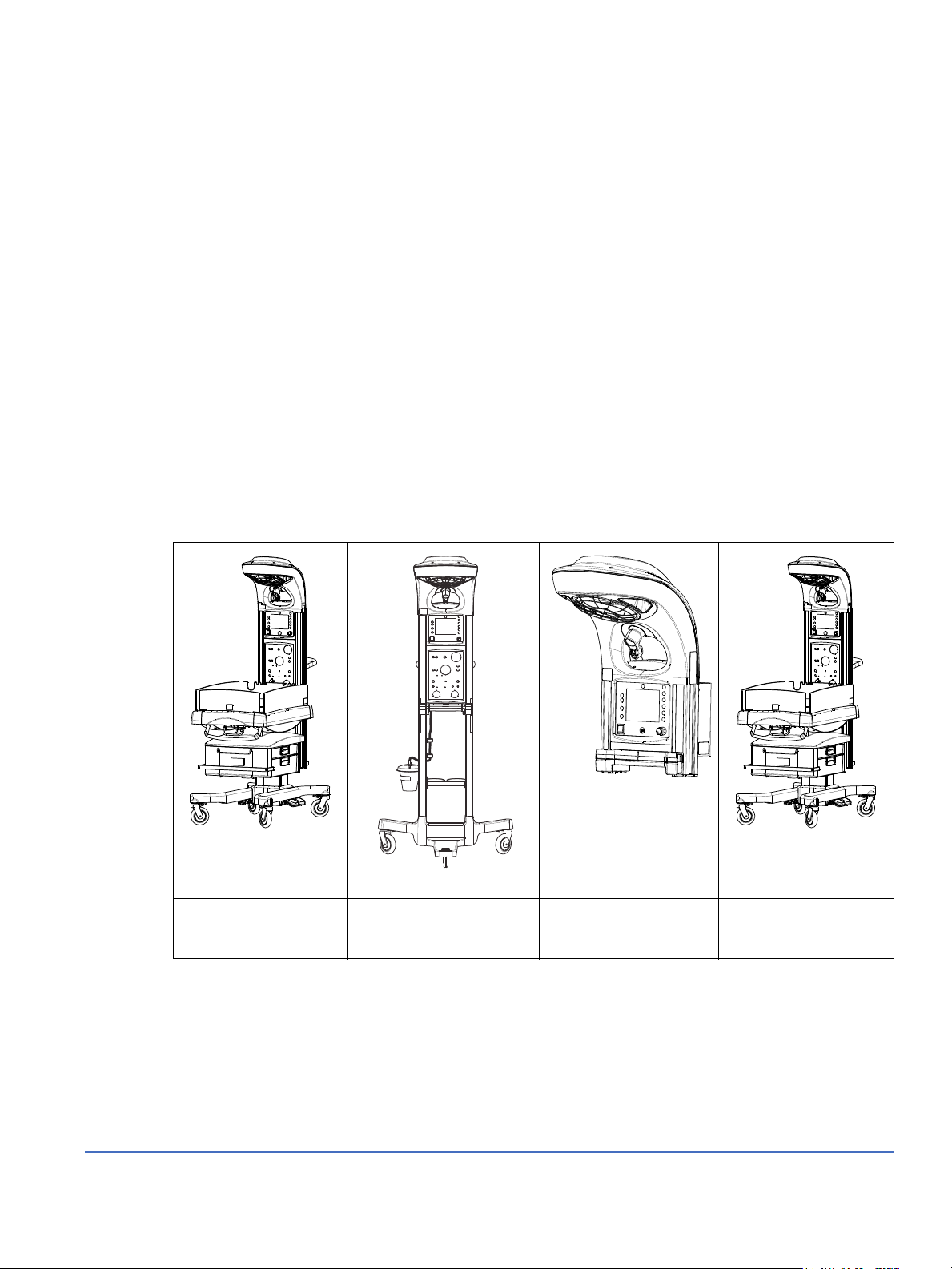
The Panda and Giraffe Warmers are each offered in a bedded model: the Panda iRes Warmer and the
Giraffe Warmer. The Panda Warmer also offers two non-bedded models: Freestanding and Wall Mount. The
model type is indicated on the label and on the device’s splash screen.
TABLE 1-1. Warmer Models
Panda iRes Warmer Panda Freestanding
Warmer (non-bedded)
Panda Wall Mount
Warmer (non-bedded)
Giraffe Warmer
1-1
Page 26
Chapter 1: Functional Description
Introduction
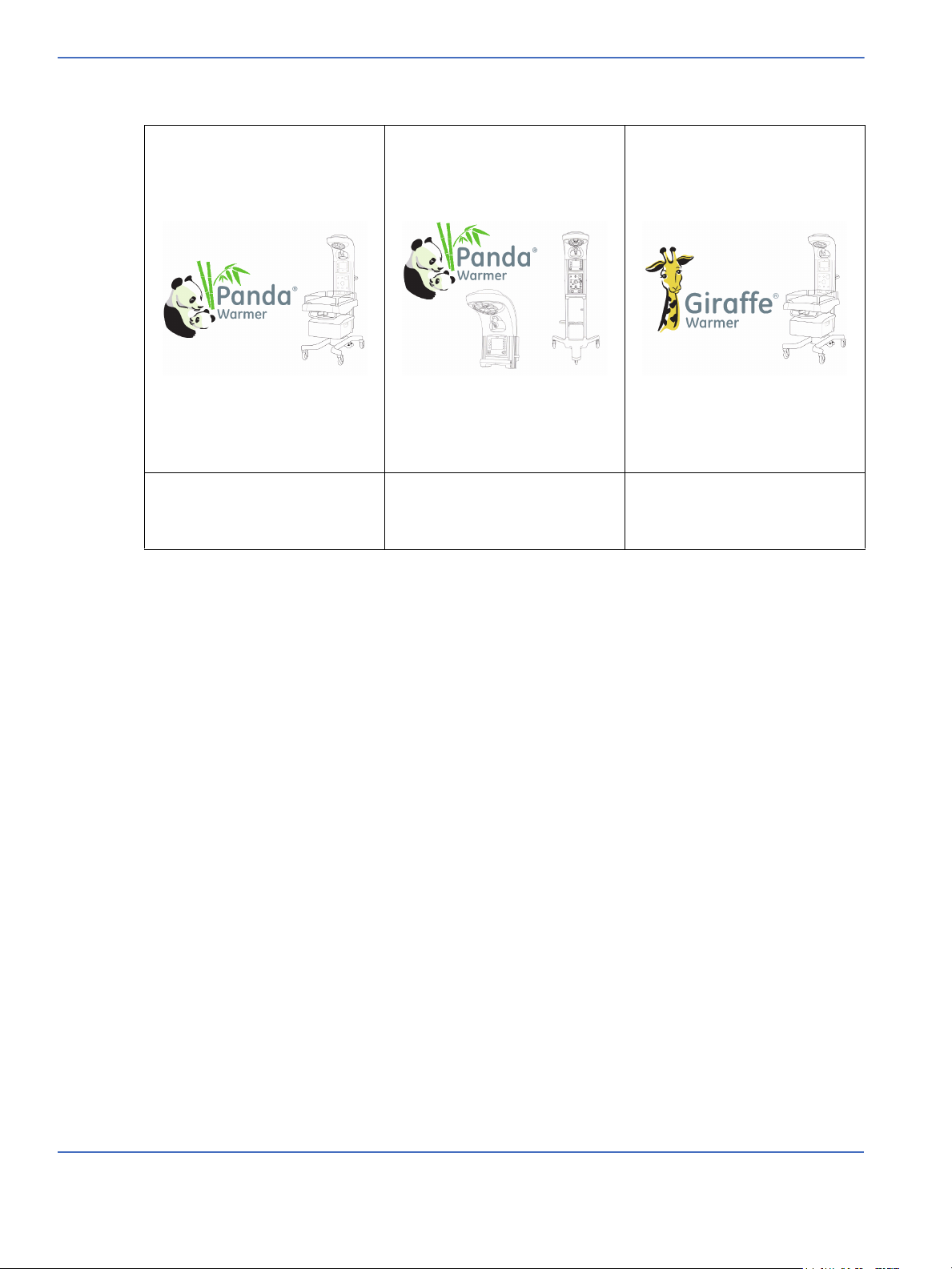
TABLE 1-2. Warmer Splash Screen Images
Panda iRes Warmer Splash Screen Panda Freestanding and Panda
Giraffe Warmer Splash Screen
Wall Mount Warmer non-bedded
Splash Screen
The information in this manual refers to all models, unless otherwise specified. The term “bedded” refers to
both the Giraffe Warmer and the Panda iRes Warmer.
The Giraffe model is intended for use in a neonatal intensive care unit. It features a mattress which can be
rotated as needed by the operator to gain better access to the patient. Also included are general
observation lights and a procedure light.
The procedure light is mounted on a ball joint so that it can be directed where needed on the bed surface.
The Panda models are intended for use in a labor and delivery unit. They also include the same general
observation lights as the Giraffe Warmer, but the procedure light is optional.
All Giraffe and Panda units feature the same heater head to house the radiant heater. Due to the small size
of the heater reflector and its compound elliptical shape, designed specifically for this product, the heater
head is very compact compared with other warmers currently on the market. This compact size limits the
area the heater head occupies over the bed surface. By leaving the area over the bed clear, the caregiver
can observe and treat the patient unobstructed. Additionally, this open area allows the head of an X-ray
machine to be placed over the patient without moving the heater head or patient.
All Giraffe and Panda units also feature optional integrated SpO
and Resuscitation Modules. The SpO2
2
option allows the caregiver to monitor the patient’s blood oxygen level, while the optional Resuscitation
Module allows the caregiver to administer forced breathing if required. The Resuscitation Module may
feature either a traditional bag and mask technology or a T-piece technology.
1-2 Service Manual
Page 27

Chapter 1: Functional Description
Introduction
An additional feature, unique among warmers is the Hands Free Alarm Silence. This is a standard feature on
all Giraffe and Panda Warmers. Alarms may be silenced just as they would with the alarm silence button,
but without touching the unit. The proximity sensor for the Hands Free Alarm Silence is located in the alarm
light panel. The alarm can be silenced by gently waving one’s hand approximately two to six inches in front
of the sensor. Both units also have a conventional alarm silence button as an alternate way of silencing
alarms.
Service Manual 1-3
Page 28
Chapter 1: Functional Description
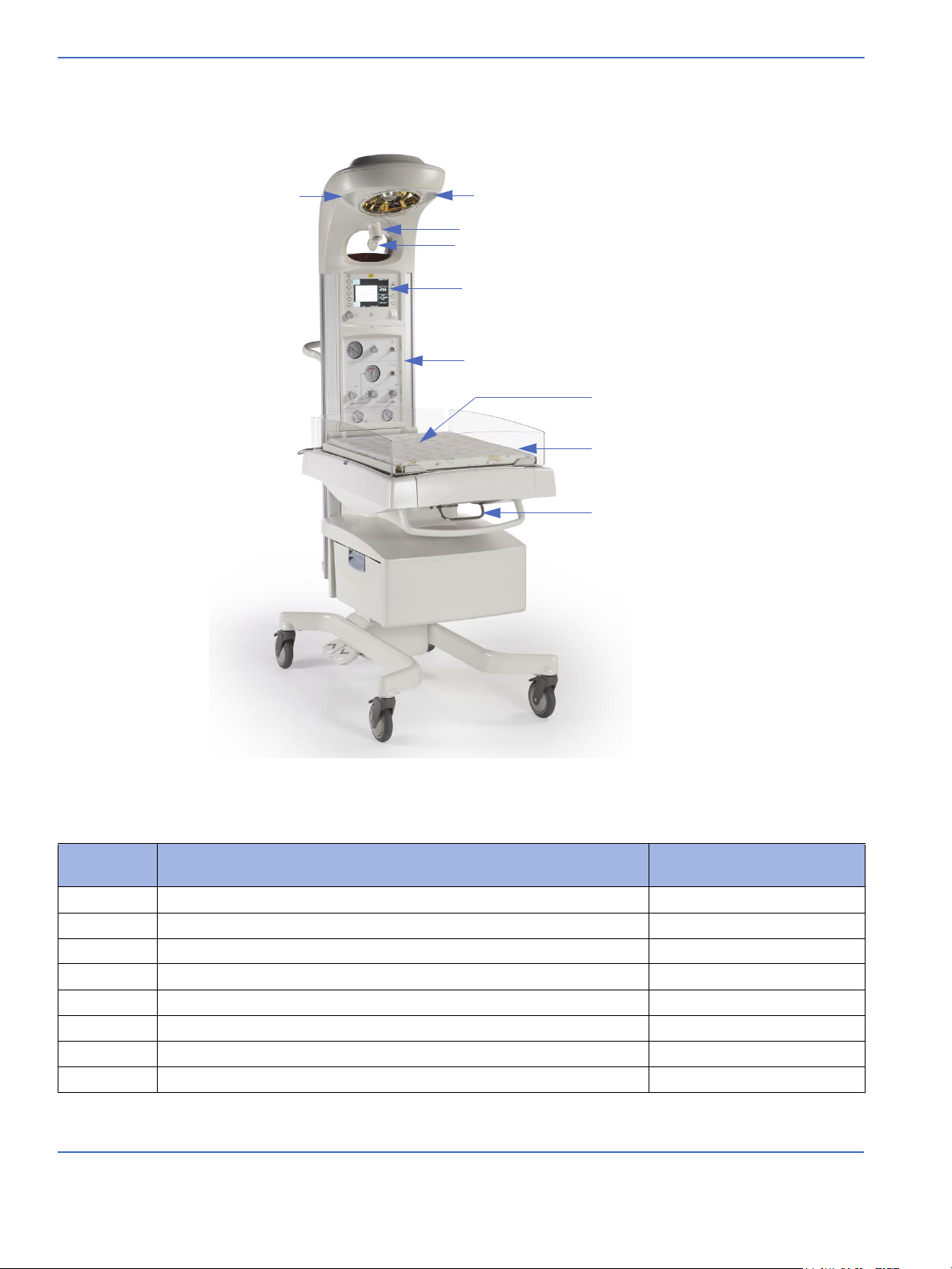
FIGURE 1-1. Panda Warmer, Front Oblique View
1
1
2
3
4
5
6
7
8
Introduction
1.1.1 Mechanical Controls and Cable Connections
Feature
Description Model
Number
1 Dimmable observation light All
2 Aimable procedure light (Optional on Panda, Standard on Giraffe All
3 Procedure light “On/Off” switch All
4 Color display screen All
5 Resuscitation system (optional) Bedded and Freestanding
6 Bed, with optional scale (bed styles are different on Giraffe and Panda) Bedded
7 Front bedside panel (bed styles are different on Giraffe and Panda) Bedded
8 Bed tilt control lever Bedded
1-4 Service Manual
Page 29
Chapter 1: Functional Description
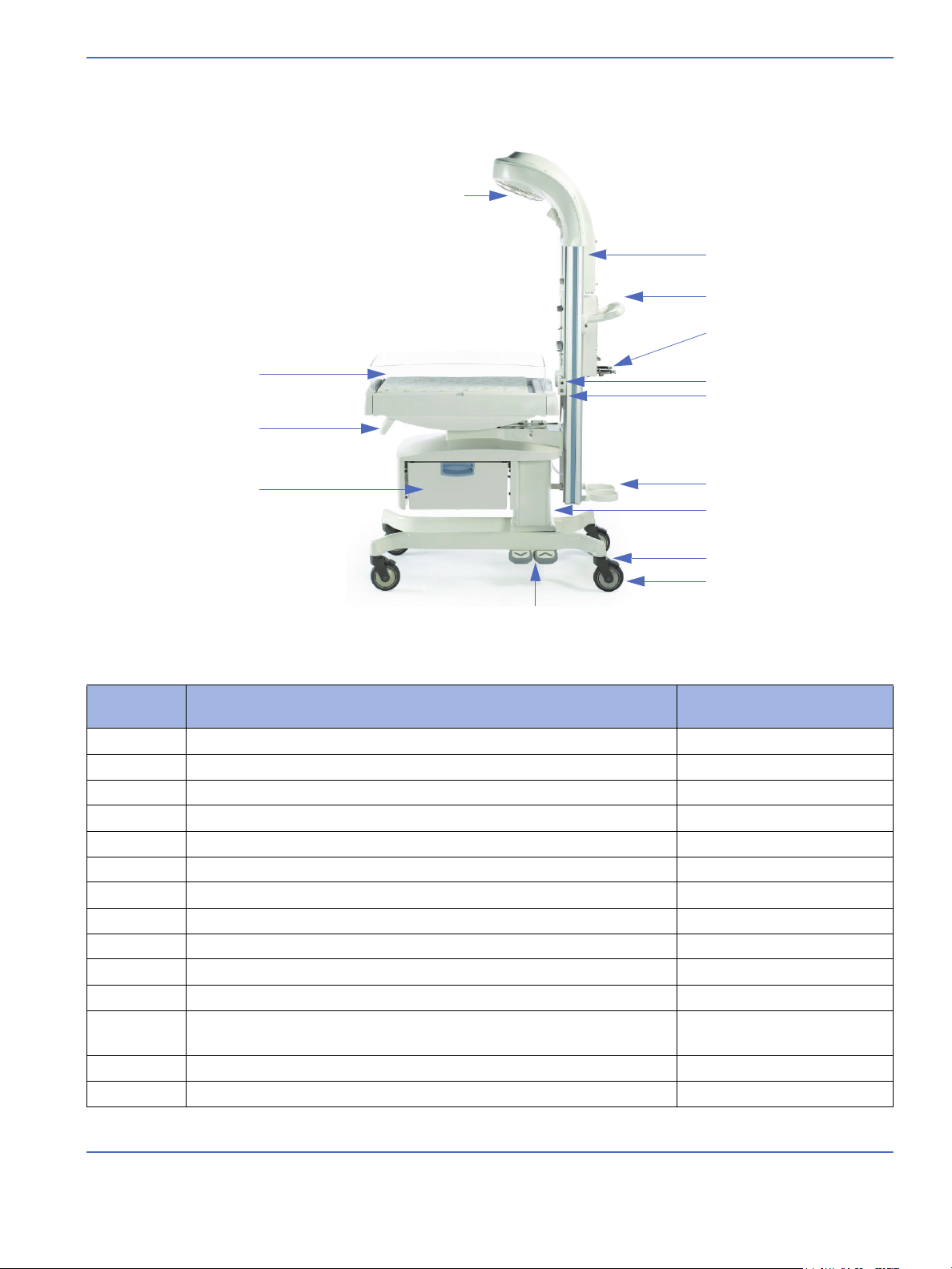
FIGURE 1-2. Panda Warmer, Side View
9
22
21
20
19
18
17
16
15
14
13
12
11
10
Introduction
Feature
Description Model
Number
9 Recessed radiant heater All
10 Side bedside panel (bed styles are different on Giraffe and Panda) Bedded
11 Front handle Bedded
12 Pass through drawer, (single-drawer or double-drawer) (optional) Bedded
13 Two bed height adjustment pedals, up and down (optional) Bedded
14 Caster wheels, 3 for Freestanding, 4 for Bedded Bedded and Freestanding
15 Brakes, 2 for Freestanding, 4 for Bedded Bedded and Freestanding
16 Elevating column (optional) Bedded
17 Tank guard (on models with yoke equipped resuscitation systems) Bedded and Freestanding
18 Scale cable connector Bedded
19 Temperature probe Jack All
20 High pressure air/oxygen yoke (on models with yoke equipped
resuscitation systems
Bedded and Freestanding
21 Maneuvering handle and cord wrap Bedded and Freestanding
22 Dovetail rail (shortened on Wall Mount, only inside on Freestanding) Bedded and Freestanding
Service Manual 1-5
Page 30
Chapter 1: Functional Description
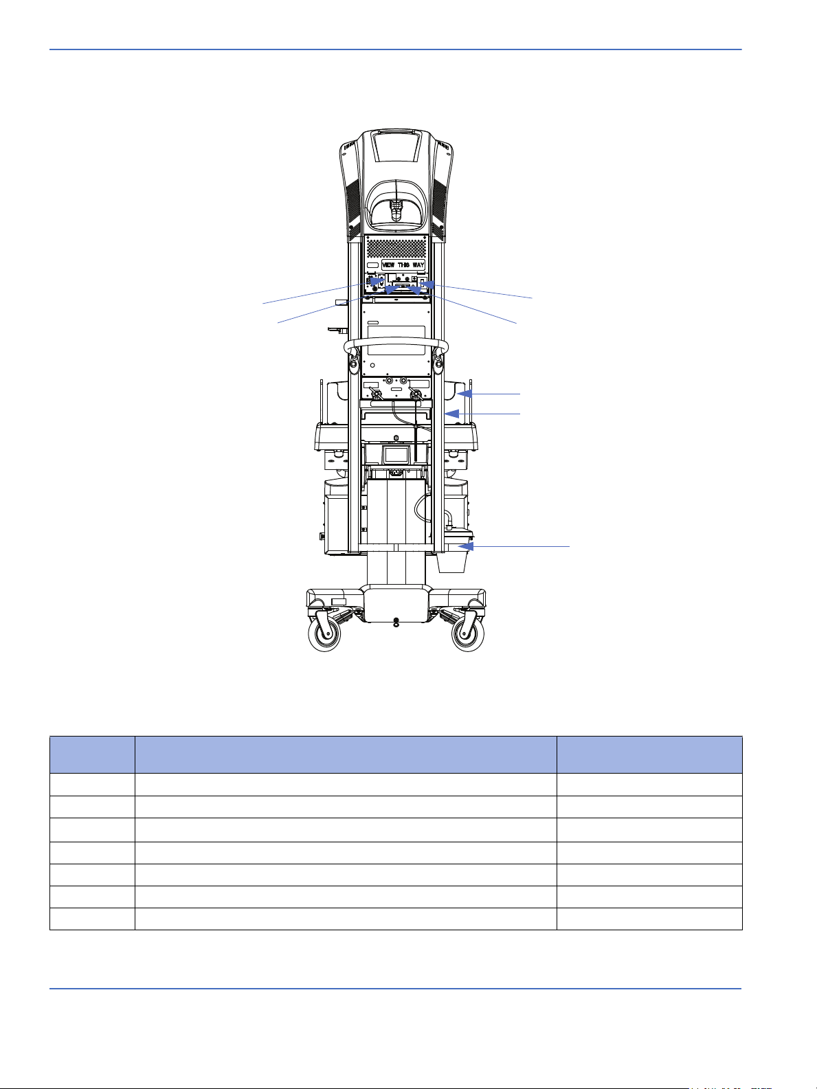
FIGURE 1-3. Panda Warmer, Rear View
28
27
24
23
26
25
29
Introduction
Feature
Description Model
Number
23 RS-232 connector All
24 Two accessory power outlets All
25 SpO
system (optional) All
2
26 Removable rear bedside panel Bedded
27 Power cord inlet All
28 Mains power switch All
29 Suction Bottle holder (only on units with resuscitation system) Freestanding and Bedded
1-6 Service Manual
Page 31

1.1.2 Controls and Displays
Masimo SET (1 or 2) Nellcor
Chapter 1: Functional Description
Introduction
Feature
Description
Number
1 Power stand-by switch - On the left below the display turns the power to the warmer on
and off.
2 SpO
logo (optional) - Indicates which SpO2 system is installed:
2
3 Oximetry key (optional) - This key retains the same function at all times and toggles SpO
on and off.
4 Mode key - To select manual or baby mode. This key retains the same function at all times
5 Temperature/power increase/decrease key - This key retains the same function at all
times
6 Baby temperature - Can be displayed in degrees Celsius or degrees Fahrenheit. The default
setting is degrees Celsius.
7 Alarm silence key - Alarms can be silenced by pushing the key above the display or by a
wave of your hand directly in front of the alarm light.
8 Help key - The key with the “?” in the upper right corner brings up the help screen that
explains alarms and functions.
9 Task keys - The five keys on the right are “soft” keys that change their function depending
on what task you wish to perform. They control equipment settings and options.
10 Dimmer knob - Controls the brightness of the observation lights.
11-12 Date and time - Displayed at the bottom of the screen.
13 Moving arrow - indicates that the processor is active
2
Service Manual 1-7
Page 32

Chapter 1: Functional Description
Mechanical Modules
1.2 Mechanical Modules
1.2.1 Heater Head Assembly
The heater head assembly contains general observation lighting, optional procedure lighting, radiant
heater, reflector, alarm light, alarm speaker, power inlet, accessory power outlets, communication port , user
input controls, graphics display, and electronic Control Boards. The heater head assembly contains the
main interfaces for the operator. The control touch panel controls the warmer, and statuses are monitored
on a color display. Radiant heat emanates from the reflector located in the heater head. All lighting and
their controls are located in the heater head.
1.2.2 Rails
The rails support the heater head, resuscitation (except for Wall Mount), and probe panel assembly.
1.2.3 Optional Resuscitation Assembly (Bedded and Freestanding Only)
The optional resuscitation assembly is located between the two rails and operates independently from the
rest of the product. The warmer may be configured with either a bag and mask resuscitation system or a
T-piece resuscitation system.
1.2.4 Probe Panel Assembly
The probe panel assembly is located between the two rails. It contains the standard connection for the
patient probe, which provides an input of the patient’s temperature to the warmer. It also contains a scale
connection so that a patient’s weight can be displayed and recorded by the warmer (when equipped with a
scale). In addition, there is an optional SpO
connection, for a SpO2 probe.
2
1.2.5 Base Assembly (Bedded and Freestanding Only)
Bedded model: The base assembly supports the rails and bed assembly. It contains supports for 4 locking
casters, so that the warmer can be moved to any location within a hospital. The mounting location for the
rails and bed assembly are separated from the caster supports by a column which adjusts in height. Two
column types are available. One column type can be adjusted manually, and the other can be adjusted
electrically by foot pedal controls on the caster supports.
Freestanding model: The base assembly supports the rails. It contains supports for 3 casters.
1-8 Service Manual
Page 33

1.2.6 Bed Assembly (Bedded Only)
The bed assembly is mounted to the base assembly via a pivot and actuator. This assembly point allows the
bed to pivot relative to the base. The pivot is normally locked, but a release handle allows the operator to
unlock the pivot and adjust the angle of the bed. Once the desired angle is achieved, the handle is released,
and the pivot locks again. There are two versions of the bed assembly. The Giraffe Warmer uses a
65 × 48 × 4 cm mattress with rounded ends, which can be translated side-to-side, and rotated. The
Panda iRes Warmer uses a fixed rectangular mattress measuring 66 × 48 × 2 cm.
1.2.7 Optional In-Bed Scale (Bedded Only)
There is a scale option, located in the bed, which can weigh the patient. The scale uses the graphics display
on the warmer to display its measured weight.
1.2.8 Optional SpO2 Module
The SpO2 probe connects to the SpO2 module. The SpO2 module uses an OEM pulse oximetry board. The
warmer includes a small circuit to isolate the power and communicate with the OEM pulse oximetry board,
so as to pass its parameters to the display without modifying the parameters or alarms. The
communication is performed using a serial data bus. The modules are procured from Masimo or Nellcor.
Chapter 1: Functional Description
Mechanical Modules
1.2.9 Giraffe Shuttle Accessory (Bedded Only)
The Giraffe Warmer and Panda iRes Warmer can be used with the Giraffe Shuttle, a mobile power source
that allows for transport of the patient between care areas within the hospital building and provides power
to the warmer. These areas include, but are not limited to, Labor and Delivery, NICU, Radiology, and
Operating Room. The warmer with the Shuttle is not intended for use outside of the hospital building.
Service Manual 1-9
Page 34

Chapter 1: Functional Description
FIGURE 1-4. System Overview
System Functions
1.3 System Functions
1.3.1 System Overview (Fully-Loaded Bedded Shown)
1-10 Service Manual
Page 35

1.3.2 Hands Free Alarm Silence
FIGURE 1-5. Hands Free Alarm Silence
This processor-controlled circuitry resides on the Alarm Light Board. (Refer to Figure 1-5.) The user input is
accomplished with an infrared emitter/receiver pair. The emitter/receiver pair is monitored by the alarm
light microprocessor, which sends the alarm silence signal to the main application processor. The main
application processor uses this signal as one of two inputs to determine whether the alarm should be
silenced. The Hands Free Alarm Silence may be enabled/disabled/disengaged through Service Mode.
Chapter 1: Functional Description
System Functions
1.3.3 Watchdog
The system incorporates smart monitoring mechanisms that allow three of the processors to monitor each
other in order to detect abnormal operation. (Refer to Figure 1-6.) The audio processor functions as the
master watchdog processor and ensures the main application processor is responding normally. If the
audio processor detects abnormal functioning of the main processor it opens the heater safety relay and
activates a high priority alarm.
The main application processor ensures the heat control processor is responding normally. If the main
application processor detects abnormal functioning of the heat control processor it opens the heater safety
relay, activates the high priority alarm and displays a system fail message. A power cycle is required to
return the system to use.
An independent hardware circuit monitors the audio processor to ensure it is functioning normally. In the
event the audio processor does not respond normally the hardware circuit will reset the audio processor
causing a system fail condition. A power cycle is required to return the system to use.
Service Manual 1-11
Page 36

Chapter 1: Functional Description
FIGURE 1-6. Watchdog
System Functions
Note: A system failure on the screen indicates the main application processor has detected abnormal
function in the system. A blank screen with a high-priority alarm indicates a problem with the main
application processor. Refer to “4.4 Troubleshooting Tables” for more information.
1.3.4 Battery Management
A lithium ion rechargeable battery is located on the Control Board. The audio processor provides charge
control and monitoring of the battery. (Refer to Figure 1-7.) The battery management integrated circuit
provides proper charging profile to prevent damage to the battery. The battery management circuitry
prevents over-discharge of the battery and system damage in the event of reverse polarity installation. In
the event of battery failure or low charge, a “super” capacitor provides one cycle (ten minutes) of power fail
indication.
1-12 Service Manual
Page 37

Chapter 1: Functional Description
FIGURE 1-7. Battery Management
System Functions
1.3.5 Power Fail
The next paragraph assumes loss of AC power and resulting loss of DC power.
A power fail is detected when the audio processor (refer to Figure 1-8) senses the 3.3 Volt power supply
below normal operating level with the stand-by switch on. This will result in a shut down of the main
application processor and initiate a power fail alarm for a minimum of 10 minutes. The lithium ion battery or
the “super” capacitor provides power for the alarm. The audio signal for a power fail alarm is a repeating
sequence of 3 beeps from a piezoelectric buzzer on the Alarm Light Board. The visual signal is one LED on
the Alarm Light Board.
The heat control processor on the Power Board has an independent circuit to detect a drop in 12 Volt power
below normal operating levels. In the event of low 12 Volt power the heat control processor will initiate a
controlled shutdown of the heater circuit. In the event of an internal malfunction resulting in loss of one
level of DC power, one or more of the processors will shut down causing the smart monitoring function to
initiate a system failure.
Service Manual 1-13
Page 38

Chapter 1: Functional Description
FIGURE 1-8. Power Failure
System Functions
1-14 Service Manual
Page 39

1.3.6 External Communication
FIGURE 1-9. Thermalink Communication
Serial communication is provided though the ThermaLink port. (Refer to Figure 1-9.) A null modem cable is
required for connection to a PC serial port. Ethernet communications are not used at this time.
A string of ASCII characters will be transmitted over the RS-232 port every 15 seconds ±5 seconds.
The string will be formatted as follows:
Unit Type with version, baby temperature, set temperature, current heater setting, mode, last recoded
weight, saturation, pulse rate, list of alarms, 00(used to note the end of the alarm list), checksum (in
hexadecimal format).
Example 1: Manual Mode with no alarms.
GWRM_1.0.7,36.3,36.5,35,M.1340,0,0,00,0d
Example 2: Baby mode with two alarms
PWRM_1.0.7,36.3,37.1,40,P,1340,0,0,16,22,00,ea
Note: Ethernet communication is not used at this time.
Chapter 1: Functional Description
System Functions
Service Manual 1-15
Page 40

Chapter 1: Functional Description
FIGURE 1-10. Touch Panel and Display
LCD Display
Touch Panel
LED Driver
Control Board
VGA
Controller
Video
RAM
PWM
IO
J5J1
Main Application
Processor
Backlight
Intensity
Control
Digital RGB
PB0 - 11
DGND
System Functions
1.3.7 Service Mode
A series of restricted service menu screens allow a technician to change system defaults, perform
diagnostics and view the unit’s PCB and software revision levels. The service mode is initiated by holding
both the Help and Alarm Silence keys during power up.
1.3.8 Display
The color VGA display is driven and powered by the Control Board. The Control Board includes a dedicated
graphics controller with on-board memory. The LCD is backlit with two low voltage LED strings. The LCD
backlit driver is located on the Control Board.
1.3.9 Touch Panel
The touch panel has membrane switches and is wired to the Control Board. (Refer to Figure 1-10.) Signals
from the switches are received by the main application processor.
1-16 Service Manual
Page 41

1.3.10 Elevating Base (Bedded Models Only)
FIGURE 1-11. Elevating Base
The elevating base assembly is powered by mains power. (Refer to Figure 1-11.) There are fuses for the
mains power on the Power Board. The power must be enabled by the elevating base relay on the Power
Board. This relay is under the control of the main application processor. Foot switches on both sides of the
unit control the elevating base movement.
Chapter 1: Functional Description
System Functions
Service Manual 1-17
Page 42

Chapter 1: Functional Description
FIGURE 1-12. Observation Lights
System Functions
1.3.11 Observation Lights
The system incorporates dimmable observation lights in the heater housing. (Refer to Figure 1-12.) Mains
power is converted to low voltage AC by a dimmable transformer located in the electronics enclosure. The
on/off control and light intensity is controlled by a potentiometer mounted to the front panel. On/off control
is achieved by a relay on the Power Board. The mains power to the observation light is fused on the Power
Board.
1.3.12 Procedure Light (Optional on Panda Warmer)
Mains power is converted to DC power by a dedicated 12V DC power supply mounted in the heater housing.
(Refer to Figure 1-13.) The light intensity ramps up progressively when the light is turned on. The slow turn
on is controlled by circuitry on the Alarm Light Board. The on-off switch on the light assembly provides an
enable signal to the slow turn on circuitry on the Alarm Light Board. Mains power to the procedure light
includes fuses on the Power Board.
1-18 Service Manual
Page 43

Chapter 1: Functional Description
FIGURE 1-13. Procedure Light
System Functions
1.3.13 Heat Control
System runs in one of three modes: Warmup Mode (refer to 1.3.13.1), Manual Mode (refer to 1.3.13.2), and
Baby Mode (refer to 1.3.13.3. Refer to Figure 1-14 and Figure 1-15.
1.3.13.1 Warmup Mode
During Warmup Mode “Check Baby” alarms are deactivated. If you do not press the “Admit Baby” key
during the first minutes after start up, the display will show “Warming...” and the radiant heater will
automatically run at 100% power. After 7 minutes, the display indicates “Warmup Complete…” and the
default heater power setting drops to 50%. The display continues to flash “Admit Baby” until you press the
“Admit Baby” key and start normal operation.
1.3.13.2 Manual Mode (assuming normal run-state, no alarms)
The user set point is heater output level from 0% to 100% in 5% increments. The main application software
passes the set point to the heat control processor. System input to the heat control processor also includes
heater calibration data from the EEPROM chip in the heat engine assembly. The heat control processor
modulates, in ½ line cycles, the power to the heater with a solid-state relay to achieve the desired power
output. Power to the heater is monitored with a solid-state power meter to ensure the proper power is
being delivered.
Service Manual 1-19
Page 44

Chapter 1: Functional Description
FIGURE 1-14. Manual Mode Heat Control
System Functions
1-20 Service Manual
Page 45

Chapter 1: Functional Description
FIGURE 1-15. Baby Mode Heat Control
System Functions
1.3.13.3 Baby Mode
The heat control processor functions identically in Baby and Manual Modes. The user input to the system in
Baby Mode is the desired skin temperature. The system measures actual skin temperature via the patient
probe. The signal is an input to the Control Board converted to a digital signal read by the main application
processor. The processor utilizes a proprietary, patented heat control algorithm to determine the optimum
heater output power. This output power is passed to the heat control processor.
Service Manual 1-21
Page 46

Chapter 1: Functional Description
System Functions
1.3.13.4 Start-up
When the unit powers on, there are a number of self-tests that occur; these are the Power On Self Tests
(POST). If a failure is detected during POST, the unit will display a system failure message on the screen,
record the event in the error log, and initiate a high priority alarm. If no failures are detected, normal startup
operation as defined in the user manual will commence.
To visually confirm the servo baby heat algorithm functionality of the warmer unit, perform the following
steps:
Note: One Temperature Simulator (part number 6600-0876-700) is required.
1. Connect the Temperature Simulator (6600-0876-700) to the warmer unit.
2. Power on the warmer unit and admit baby.
3. Use the Temperature Simulator to set Baby Temp to 36.0° C. Press the button to go to Baby Servo Mode.
4. Set the Temperature Set Point to 36.0° C.
5. Disconnect the Temperature Simulator and verify the heater output shows 0% or 0 red bars. Also, an
alarm is generated to confirm probe check connection.
6. Reconnect the Temperature Simulator to the warmer. The heat output should be 50% or 10 red bars.
7. Wait for 60 seconds. There should be no changes to the heat output.
8. Adjust the Temperature Simulator to 36.2° C Baby Temperature and wait for about 30 seconds. You
should see a decrease in the heat output (5% or 1 red bar every 30 seconds).
9. Adjust the Temperature Simulator to 35.8° C Baby Temperature and wait for 30 seconds. You should see
an increase in the heat output (5% or 1 red bar every 30 seconds).
10. Adjust the Temperature Simulator to 35.6° C Baby Temperature and wait for 30 seconds. You should see
an increase in the heat output (15% or 3 red bars every 30 seconds).
Note: In steps 8-10, the heat output will continue to increase/decrease until it reaches 100% or 0% heat
output.
11. Adjust the Temperature Simulator to 36.4° C Baby Temperature. Heat output should decrease to 0% or
0 red bars immediately (no progression).
12. Adjust the Temperature Simulator to 35.4° C Baby Temperature. Heat output should increase to 100%
or 20 red bars immediately (no progression).
1.3.13.5 Safety Relay
The system incorporates a safety relay that interrupts power to the heater if one of the following conditions
occurs:
• Over-temp thermostat opens in the heater head.
• Main application processor detects a fault condition that requires interruption of heater power.
• Smart monitoring processor detects malfunction of main application processor.
• Audio processor detects a fault condition that requires interruption of heater power.
• Heat control processor detects a fault condition that requires interruption of heater power.
1-22 Service Manual
Page 47

1.3.14 Scale (Bedded Models Only)
FIGURE 1-16. Scale Interface
FIGURE 1-17. Pulse Oximetry (SpO2)
The scale communicates with the main processor via RS-485. (Refer to Figure 1-16.) The connector for the
scale cable is in the probe panel housing. The scale is powered by 12V DC supplied by the control board.
The power circuit includes over-current protection.
Chapter 1: Functional Description
System Functions
1.3.15 SpO
The Pulse Oximetry (SpO2) option utilizes an OEM module commonly used in other monitoring equipment.
For units that have the SpO
in the probe panel housing. (Refer to Figure 1-17.) The probe panel housing contains the OEM module and
an SpO
via serial communication. The OEM module output is communicated to the user visually or audibly as
required.
2
option, the SpO2 patient probe connects to the SpO2 module which is located
2
interface board. Oximetry parameters and alarms are passed to the main application processor
2
Service Manual 1-23
Page 48

Chapter 1: Functional Description
FIGURE 1-18. Alarms
System Functions
1.3.16 Alarms
Alarms are indicated to the user both visually and audibly. Visual alarms are provided via the LED Array
located on the Alarm Light Board. (Refer to Figure 1-18.) The LED array is controlled on and off by the alarm
control signal provided by the main application processor or audio processor on the Control Board. Alarm
audio is generated by an audio amplifier also under control of the audio processor in response to a
command from the Main Application Processor.
1-24 Service Manual
Page 49

1.3.17 Equipment Grounding
1.3.17.1 Grounding and Insulation Design for Safety
The grounding and insulation design of the Giraffe and Panda Warmers ensures all mains circuitry is
separated from the operator and patient by one of two methods:
• Basic insulation with a grounded metal barrier
• Double/reinforced insulation
The radiant heater reflecting dish, heater duct, electrical enclosure, and elevating base all rely upon basic
insulation of the wires and a grounded metal barrier.
The heater head housing and main bracket (on elevating base models) rely on double/reinforced insulation.
For the heater head housing, the two parts of the housing along with the wire insulation form a double
insulation system. For the main bracket, a sheet of insulating material is fitted between the bracket and the
elevating column. This insulation, along with the insulation on the wires of the elevating base form a double
insulation system.
1.3.17.2 Grounding and Insulation Design for Electromagnetic Compatibility
Chapter 1: Functional Description
System Functions
The device incorporates grounding for ESD/EMC compliance. The dovetail rails and legs of the device are
grounded to comply to ESD susceptibility standards.
1.3.17.3 Ground and Insulation Design for Convenience
The device incorporates IEC appliance outlets for attachment of approved accessories that include a third
wire ground. The device also incorporates a ground equalization potential post, which allows for the
interconnection of equipment grounds if required.
Service Manual 1-25
Page 50

Chapter 1: Functional Description
FIGURE 1-19. AC/DC Power Distribution
System Functions
1.3.18 AC/DC Power Distribution
1-26 Service Manual
Page 51

1.4 RS-232 Serial Data
Warning: The computer or RS-232 monitor’s user program must continuously check the data
link. The program should constantly verify connection to the control panel and check for
updated data.
Note: In the event of a power failure, all serial communication will cease until power is restored.
1.4.1 RS-232 Connector
The Nurse Call and the serial data output share the same female, nine pin, d-type connector.
• Pin 2: Receive Data (incubator input)
• Pin 3: Transmit Data (incubator output)
• Pin 5: Gnd (Signal Ground)
1.4.1.1 Cable Requirements
The user interface cable must have capacitance less than 1500 pF. It should be a shielded cable such as
Belden 9611 with AMP shielding kit 748046-1 and ferrule 747579-8.
Chapter 1: Functional Description
RS-232 Serial Data
1.4.2 Data Stream
The data stream from the Panda and Giraffe products is repeated every two seconds. The RS-232
parameters are 116000 bps baud rate, no parity, 8 data bits, and one stop bit. The data is in ASCII format;
the string is described below:
PWRM_2.0.0,36.8,36.4,0,P,0,0,0,00,29
HYB This is the product code.
2.0.0 This is the control board software revision (thermoregulation in the startup screen).
36.8 Temperature from Patient Probe #1.
OPEN Temperature from Patient Probe #2. OPEN represents no probe connected.
36.4 Baby (Servo) mode desired temperature setting.
0Heater power.
P • Baby (Servo) Mode = P
• GWRM = Giraffe Warmer
• PWRM = Panda Warmer
• PNBW = Panda Non-Bedded Warmer
• Manual Mode = M
Service Manual 1-27
Page 52

Chapter 1: Functional Description
RS-232 Serial Data
1.4.3 Nurse Call
1.4.3.1 Contact Ratings
• Maximum resistive load: 4 VA
• Maximum DC switching voltage: 100 VDC
• Maximum switching current: 0.25 A
• Maximum carrying current: 0.50 A
1.4.3.2 Connector
The Nurse Call contacts and the serial data output share the same female, nine pin, d-type connector.
Pin 6: Closed contact under normal conditions, that is, power on, no alarm (recommended
configuration).
Pin 1: Common contact.
Pin 9: Open contact under normal conditions, power on, no alarm. These contacts are not
powered. They only provide closure.
1.4.3.3 Nurse Call Signals
Nurse Call Signal
Incubator Status
Normal Closed Open
Alarm Open Closed
Pwr switch off or pwr fails Open Closed
Nurse Call cable disconnected Open Open
Pins 1 and 6 Pins 1 and 9
1-28 Service Manual
Page 53

Chapter 2: Installation, Maintenance, and Checkout
2.1 Warmer Maintenance Schedule
The unit shall be maintained in accordance with the preventative maintenance procedures detailed in this
Service Manual. Service maintenance must be performed by a technically competent individual. The
Checkout must be performed after installing the warmer.
2.1.1 Operator Maintenance
This schedule lists the minimum frequencies. Always follow hospital and local regulations for required
frequencies.
2.1.1.1 After Each Patient Use
• Clean the resuscitation system and disinfect as required.
• Clean re-usable suction canister or replace single-use canister.
• Replace suction tubing between canister and the patient.
• Clean the warmer between each patient, or more frequently as required.
Inspect suction tubing that is routed through the dovetail rail. Replace the tubing as described in the
cleaning instruction in the resuscitation operator supplement, as required.
2.1.2 Service Maintenance
This schedule lists the minimum frequencies. Always follow hospital and local regulations for required
frequencies.
2.1.2.1 Annually
• Perform the electrical safety checks as described in this service manual (refer to section 2.2.3).
• If present, calibrate the scale as described in this service manual (refer to section 3.1).
• Perform the resuscitation system service checkout as described in the Resuscitation Systems
service manual.
2.1.2.2 Every Two Years
• Replace the lithium-ion battery as described in this service manual (refer to section 5.4.3).
Note: The lithium-ion battery is used to sound the power failure alarm and to power memory circuits
during a power failure
• Perform the complete blender maintenance as described in the Resuscitation Systems service
manual.
2-1
Page 54

Chapter 2: Installation, Maintenance, and Checkout
Installation and Service Checkout Procedures
2.1.2.3 Service tools
Heater dish alignment laser kit (includes holder) (takes
three #392 1.55V button cells or equivalent)
Laser holder (includes O-ring) M1118362
NULL Modem Cable M1128795
Light gray touch-up paint (Munsell .16GY8.56-0.44
chroma), 18 ml
Masimo SET 1 electrical leakage test cable 2006036-001
Masimo SET 2 electrical leakage test cable M1230051
Nellcor electrical leakage test cable M1237129
Crank handle kit M1163421
Note: The resuscitation systems service tools are described in the Resuscitation Systems service manual.
Note: A straight-line laser level (with two wall leveling capability) or a combination of T-square and Plumb-
bob is recommended for accurate heater alignment of Freestanding and Wall Mount Warmer
models.
2.2 Installation and Service Checkout Procedures
Warning: Use only the specific power cord supplied with the unit. Use of an
unapproved power cord could result in damage to the unit or injury.
M1118361
6600-0714-200
Except for Panda Wall Mount Warmer model, all other warmer models do not require any installation. After
removing the warmer unit from the shipping package, perform the following checkout procedures before
putting the unit into use.
For Panda Wall Mount Warmer model, refer to the installation instructions in Appendix E to mount and
secure the unit on the wall and do heater alignment. Then perform the following checkout procedures
before putting the unit into use.
2.2.1 Mechanical Checks
Warning: Do not perform the preoperational checkout procedure while the patient
occupies the unit.
Warning: Complete the preoperational checkout procedure section of this manual
before putting the unit into operation. If the equipment fails any portion of the
checkout procedure it must be removed from use and repaired.
1. Disconnect the power cord for the mechanical portion of the preoperational checkout procedure.
2. Examine the power cord for any signs of damage. Replace the cord if damage is evident.
3. Check that the cord retainer/accessory outlet guard on the back of the control panel is in place.
4. Examine the unit overall for any damaged or missing parts.
5. Examine the unit for any missing or damaged labels. Make sure the labels are attached in the proper
locations. For a list of labels and their proper locations, refer to section 6.11.
2-2 Service Manual
Page 55

6. For Bedded and Freestanding models, check that all the casters are in firm contact with the floor and
that the unit is stable. Lock the caster brakes and check that they hold the unit in place. Release the
brakes and check that the unit moves smoothly.
7. For Bedded models check the operation of all four bedside panels. The bedside panels should lock
securely in the upright position.
8. For Bedded Models, check the operation of the bed tilt mechanism. When you squeeze the tilt control
and push down on the foot of the bed the head of the bed should raise easily, and should stay in
position at any angle along its tilt path when you let go of the tilt control. The bubble levels on the side
bedside panels indicate the mattress is level.
9. Check the movement of the Procedure Light Assembly (if equipped). Ensure movement is smooth and
the light can be positioned at each corner of the mattress.
10. For Freestanding model, inspect the fasteners that attach the rails, the mounting blocks, and the base
together to ensure the joints are secure and tight.
11. For wall mount model, make sure the bracket is securely mounted on the wall and all the screws
attaching the heater head to the bracket are tight.
2.2.2 Controller Checks (Figure E-2)
Warning: Do not use the warmer in the presence of flammable anesthetics; an
explosion hazard exists under these conditions.
Chapter 2: Installation, Maintenance, and Checkout
Installation and Service Checkout Procedures
Warning: Always connect the warmer directly to a hospital grade wall outlet.
Connecting to a power strip or another piece of equipment may result in safety and
ground integrity issues.
1. Make sure the power cord is connected to the outlet on the unit and to the rated power supply.
2. Switch on the power at the mains switch on the back of the unit, and at the standby switch on the front
control panel. Verify the following:
• The model type indicated on the screen matches the type of unit (Panda or Giraffe, bedded or nonbedded)
• All the displays and indicators light
• The software revision appears
• The prompt tone begins
3. Press the “Admit Baby” key to enter normal operation in Manual Mode. Select Heater Power percentage
to silence the prompt tone.
4. Connect the baby temperature probe to the jack on the right side of the bed. If using a warmer with an
In-bed scale, the temperature probe jack is located above the In-bed scale connection.
5. Check the patient probe. Warm it by placing it between your fingers, and verify that the baby
temperature reading increases.
6. Unplug the patient probe and change the warmer to Baby Mode. Check that both visual and audio
alarms trigger in the Baby Mode. Silence the alarm by using either the alarm silence key or the Hands
Free Alarm silence.
7. Return the warmer to Manual Mode by pressing the “Mode” key. Select a Heater Power setting to
silence the prompt tone.
8. If the unit is equipped with an elevating bed, check the operation of the bed elevation mechanism.
Raise and lower the bed along its entire travel range, checking that the mechanism operates smoothly.
Check that the raise and lower bed pedals on both sides of the unit raise and lower the bed height.
Service Manual 2-3
Page 56

Chapter 2: Installation, Maintenance, and Checkout
Installation and Service Checkout Procedures
9. If either the scale or oximetry option is installed, push the “About” key on the main help menu and check
to ensure that their current software revision appears.
10. Check the Observation Lights function and Procedure light function (if equipped).
11. Check the power failure alarm and the battery-backed-up memory. Make note of the current control
mode and temperature settings and wait one minute, then unplug the warmer from the wall outlet. An
alarm should sound and the power failure indicator should light. Wait one to two minutes and plug the
warmer back in. Verify that the alarm cancels and that the warmer returns to the same control mode
and temperature settings it displayed before the power interruption.
Note: A fully charged battery should supply the power failure alarm for 10 minutes minimum
(IEC 60601-2-19 clause 101.3). If the alarm is tested for the full 10 minutes, the warmer must be run
at least two hours to recharge the battery before it is used with a patient. Total recharge time is
10 hours. The battery charges only when the unit is powered on.
2.2.3 Electrical Safety Tests
Use an approved electrical safety analyzer to test the unit’s ground continuity and leakage current.
For reliable leakage current readings the ground resistance check should be performed first. Follow the
operating instructions supplied by the manufacturer of the electrical safety analyzer to verify the following:
2.2.3.1 Ground Resistance Check
1. Measure the resistance between the ground pin on the line cord plug and exposed metal of the
electronic enclosure. The ground resistance must be less than 0.2 Ohms.
2. Measure the resistance between the ground pin on the line cord plug and ground pin on the appliance
outlet connectors. The ground resistance must be less than 0.1 Ohms.
Note: Not all metal components are safety ground bonded. Only the heater reflector, heater duct, power
supply mounting bracket(s), electrical enclosure and elevating base are required to be safety ground
bonded. When servicing involves disturbing the ground bonds of these components the ground
integrity should be verified.
2.2.3.2 Earth Leakage and Chassis Leakage Current
Note: Wait 30 seconds after powering on before taking readings.
For 115 VAC rated devices:
1. In normal condition and in all possible operating modes the leakage current shall be less than 180
microamperes.
2. If required by local ordinances, in single fault condition and in all possible operating modes the leakage
current shall be less than 200 microamperes.
For 220-230-240 VAC rated devices:
1. In normal condition and in all possible operating modes the leakage current shall be less than 360
microamperes.
2. If required by local ordinances, in single fault condition and in all possible operating modes the leakage
current shall be less than 500 microamperes.
2-4 Service Manual
Page 57

Chapter 2: Installation, Maintenance, and Checkout
2.2.3.3 Patient Lead Leakage Current
Note: Wait 30 seconds after powering on before taking readings.
Mounting the Universal Adapter Plate
Patient lead leakage current shall be measured between all the leads of the SpO
together and ground. For the service tool part number, refer to section 2.1.2.3.
For AC lead leakage current
1. In normal condition in all possible operating modes the patient lead leakage current shall be less than
100 microamperes.
2. If required by local ordinances, in single fault condition in all possible operating modes the patient
leakage current shall be less than 500 microamperes.
For DC lead leakage current
1. In normal condition in all possible operating modes the patient lead leakage current shall be less than
10 microamperes.
2. If required by local ordinances, in single fault conditions in all possible operating modes the patient lead
leakage current shall be less than 50 microamperes.
Note: The isolation of the patient temperature probe is dependent upon the insulation of the patient
temperature probe. These probes are 100% tested and do not require retesting. If so desired, the
patient temperature probe can be tested by wrapping in foil or submerging in normal saline 6
inches (15 cm) of the part of the probe that attaches to the patient. Measurements shall be taken
from the conducting medium. The patient lead leakage current limits listed above are applicable.
2.3 Mounting the Universal Adapter Plate
connector shorted
2
The universal adapter plate allows bottle slides and additional brackets to mount to the rail system.
To mount the universal adapter plate:
1. Using the provided hex key, loosen the two mounting screws (1) on the side of the adapter plate.
2. Place the adapter plate in position on the rail.
3. Tighten the two mounting screws.
To release the adapter plate, loosen the mounting screws.
Service Manual 2-5
Page 58

Chapter 2: Installation, Maintenance, and Checkout
Scale Checkout Procedures
2.4 Scale Checkout Procedures
2.4.1 Visual Inspection
1. Examine the scale parts for evident signs of damage. Examine the scale connector to make sure it is
tightly assembled. Check for bent pins. If any of the parts are damaged replace them.
2. Ensure there is no mechanical interference between the scale cable and the unit.
3. Ensure the scale cable is not crossing over a corner tray of the bed. Move the corner tray if necessary.
FIGURE 2-1. Cable Not Crossing a Tray (Correct) FIGURE 2-2. Cable Crossing a Tray (Incorrect)
2.4.2 Center Weight Check
1. Turn off the bed. Clear all objects from the bed, and ensure only the clear plate remains on the scale.
2. Ensure the bed is level.
3. Turn on the bed, and go to the service screen.
4. Record the SC value on the screen, and name it SC1. The SC1 value must be in the 9900 to 11000 range.
5. Place a 5 kg weight on the center of the scale on the bed. (See location A in Figure 2-3.)
6. Record the SC value on the screen, and name it SC2.
7. Subtract SC1 from SC2. The value must be 5000 +/- 10.
2.4.3 Off Center Weight Check
1. Turn off the bed. Clear all objects from the bed, and ensure only the clear plate remains on the scale.
2. Ensure the bed is level.
3. Turn on the bed, and go to the service screen.
4. Record the SC value on the screen, and name it SC3. The SC3 value must be in the 9900 to 11000 range.
5. Place a 5 kg weight on one corner of the scale on the bed. (See location B1 in Figure 2-3.)
6. Record the SC value on the screen, and name it SC4.
7. Subtract SC3 from SC4. The value must be 5000 +/- 10.
8. Place a 5 kg weight on the second corner of the scale on the bed. (See location B2 in Figure 2-3.)
9. Record the SC value on the screen, and name it SC5.
10. Subtract SC3 from SC5. The value must be 5000 +/- 10.
11. Place a 5 kg weight on the third corner of the scale on the bed. (See location B3 in Figure 2-3.)
12. Record the SC value on the screen, and name it SC6.
13. Subtract SC3 from SC6. The value must be 5000 +/- 10.
14. Place a 5 kg weight on the fourth corner of the scale on the bed. (See location B4 Figure 2-3.)
15. Record the SC value on the screen, and name it SC7.
2-6 Service Manual
Page 59

Chapter 2: Installation, Maintenance, and Checkout
16. Subtract SC3 from SC7. The value must be 5000 +/- 10.
FIGURE 2-3. Weight Placement Locations
Scale Checkout Procedures
2.4.4 Load Cell Check
SENSITIVE TO ELECTROSTATIC DISCHARGE CAUTION
An Electrostatic Discharge (ESD) Susceptibility symbol is displayed to alert service personnel that
the part(s) are sensitive to electrostatic discharge and that static control procedures must be
used to prevent damage to the equipment.
1. Perform the scale calibration procedures described in Chapter 3, “Calibration.”
2. Turn off the bed. Make sure no mechanical interference (loose screws, etc.) exists, and the scale cable is
routed properly.
3. Turn on the bed, and go to the service screen.
4. Check the displayed SC values, and confirm that the values do not change more than 5 counts total.
5. If the SC values change more than 5 counts, 1 or both load cells might be defective. Perform the
following steps:
a. Remove the scale top tray and the control board cover to access the load cell connectors on the
control board.
b. Disconnect 1 load cell from the control board at a time, and check the SC value. If the SC values
change 5 counts or fewer after disconnecting the load cell, the disconnected load cell is defective
and must be replaced.
Service Manual 2-7
Page 60

Chapter 2: Installation, Maintenance, and Checkout
Scale Checkout Procedures
2-8 Service Manual
Page 61

Chapter 3: Calibration
3.1 Scale Calibration (Bedded Models Only)
Note: For EU Member States, this scale has been designed and manufactured in accordance with the
non-automatic weighing instruments (NAWI) directive, 2009/23/EC. To ensure complete
compliance to the Directive, have the unit calibrated by an accredited local test authority. If you are
unable to identify a test authority, contact your GE representative or distributor for assistance.
Periodic re-verification (calibration) of the scale must be performed in accordance with the National
Regulations Governing Legal Metrology. The required re-verification frequency will vary by country. Contact
your local weights and measures authority for more information.
Note: One 5 kg Certified Test Weight (GE part number 6600-0209-800) is required to perform the
calibration procedure.
1. Clear all objects from the bed and ensure only the mattress and clear plate remain on the scale.
2. Turn off the bed. Ensure the bed is level.
3. Enter service screen by turning on the bed while holding the Help and Alarm Silence keys
until you hear 2 tones (approximately 5 seconds).
4. On the Main Menu, select Scale Calibration and then Manual Calibration.
5. Use the up/down arrow keys to set the gram value of the known test weight, and press the Enter key.
6. When prompted, clear all objects from the bed.
7. Press the Start key. Scale Obtaining Tare is displayed.
8. When Apply Test Weight is displayed, place the weight on the center of the bed and press the OK key.
9. If calibration is successful, Calibration Successful is displayed. If not, press the Recal key and repeat
the procedure.
10. Do one of the following:
–Press the Save key to save the new calibration constants.
–Press the Abort key to retain the original setting.
11. Power cycle the unit to exit service mode and enter operation mode.
12. Verify the accuracy of the scale by performing a weighing cycle using the test weight. The measured
value should be the test weight +/- 10 g.
13. Perform the scale checkout procedures described in Chapter 2, “Installation, Maintenance, and
Checkout.”
3-1
Page 62

Chapter 3: Calibration
Scale Calibration (Bedded Models Only)
3-2 Service Manual
Page 63

Chapter 4: Troubleshooting
4.1 Service Mode
To access the main service menu, turn on the unit and hold the Help and Alarm Silence keys until
you hear two tones (approximately 5 seconds) and release. To exit service mode, it is necessary to power
down the unit.
Note: If the unit will not boot up, the service mode can be accessed by setting control board dip switch
position one (1) to ON and turning on mains power. The default position of all 8 dip switch positions is
OFF.
Note: For versions of application software 1.0.9 and earlier, refer to Appendix D for instructions about
accessing and using service software.
4.1.1 Unit Information
From the service mode main menu, access the Unit Information screen by pressing the ? (help) key.
When finished, press the ? (help) key again to return to the previous menu.
4.1.2 Main Menu
The service mode main menu provides the following functions:
• Operation Settings
• Scale Calibration
•Date/Time
• Diagnostics
•Set Defaults
Use the UP/DOWN arrow keys to highlight menu choices and press the select key to display the desired
menu.
4-1
Page 64

Chapter 4: Troubleshooting
Service Mode
4.1.3 Unit Info Menu
The Unit Info menu displays the following information:
• Type Giraffe or Panda (factory configured)
• Version of Main Application and Service Application
• Version of Heater Control, Audio, and Alarm Board Processors
• Version of Scale and SpO
• EPROM ID’s for Control, Power, Alarm, and SpO
• Language
• Power Fail minutes and battery voltage.
(if present)
2
board (if present)
2
Note: Absence of data in the SpO
option. Otherwise, absence of data indicates a communication failure.
area of the screen is normal when the unit does not have the SpO2
2
4-2 Service Manual
Page 65

4.1.4 Operation Settings
This menu enables users to customize the behavior of alarms, user functions, and displayed units by setting
default values for the parameters and options listed in the following table.
Feature Available Settings US Defaults International Defaults
Patient temp. alarm 0.5°C / 1.0°C 1.0°C 1.0°C
Check patient alarm disabled 5% - 50% 25% 25%
Man. temp. alarm Off / 0.5°C / 1.0°C Off Off
Alarm volume 0 / 1 / 2 / 3 3 3
Hands free silence Enable / Disable /
Bed elevate (for Bedded Warmers
with Elevating Base)
Bed elevate (for Bedded Warmers
with Fixed-Adjustable Base,
Freestanding Warmers, and Wall
Mount Warmers)
Temp. units C / C Only / F C C Only
Scale units grams / lbs-oz /
Scale resolution 10/5 grams 10 grams 10 grams
Language Many English English
Low pulse rate limit* 25 - 110 100 100
High pulse rate limit* 111 - 240 200 200
Low saturation limit** 20 - 99 85 85
High saturation limit** 86 - 100 100 100
SpO
alarm suspension on startup 0 / 15 / 30 15 15
2
SpO
averaging (Masimo only) 2-4 / 8 / 16 8 8
2
SpO
sensitivity (Masimo only) Normal / Maximum Normal Normal
2
SatSeconds (Nellcor only) Off, 10, 25, 50, 100 Off Off
SpO
2
SpO
Response Mode (Nellcor only) Normal / Fast Normal Normal
2
SpO
Display (Nellcor only) Pleth / Blip Pleth Pleth
2
View Large / Normal Large Large
SpO
2
Pulse tone volume, Panda 0/ 1 / 2 / 3 / 4 1 1
Time Format 0/ 1 / 2 / 3 / 4 12 24
Date Format YYYY/MM/DD MM/DD/YYYY DD/MM/YYYY
APGAR TONES (Giraffe Only) ON/OFF OFF OFF
Disengaged
Enable / Disable /
Disengaged
Enable / Disable /
Disengaged
grams only
MM/DD/YYYY
DD/MM/YYYY
Chapter 4: Troubleshooting
Service Mode
Enable Enable
Enable Enable
Disengaged Disengaged
grams grams only
* The Low pulse rate limit can be set only between 25 and the High pulse rate limit -1.
The High pulse rate limit can be set only between the Low pulse rate limit +1 and 240.
Service Manual 4-3
Page 66

Chapter 4: Troubleshooting
Service Mode
** The Low saturation limit can be set only between 20 and the High saturation limit –1.
The High saturation limit can be set only between the Low saturation limit +1 and 100.
The Operation Settings menu screen appears as follows:
4.1.5 Scale Calibration
This menu displays the Scale Recalibration Count (SR) and Corrected value (SC). It also displays Scale
software revision, model, resolution code and POST (power on self test) results.
Note: For versions of Application Software 1.0.9 and earlier SR represents Scale Raw Value.
Menu selections:
• Manual Cal (refer to “3 Calibration” for details).
• Check Weight. Used to verify the correct weight is reported once calibration is complete.
4-4 Service Manual
Page 67

4.1.6 Date/Time
This menu displays two primary data sets Current Time and New Time.
Current Time displays the current day of the week, day, month, year, hour, minutes and seconds.
New Time displays the current time until changes are made to the parameters listed on the left of the
screen. The user changes the New Time settings by using the UP/DOWN arrow keys and select button. Once
the desired settings are displayed in the New Time section they may be used to modify the current settings
by pressing the “SET DATE/TIME” key.
To set only the hour, minute or second, highlight the hour, minute or second in the left hand menu and press
the select key. Adjust as needed using the UP/DOWN arrow keys. Then press the Hour Only, Minutes Only or
Seconds only key as appropriate.
Chapter 4: Troubleshooting
Service Mode
Service Manual 4-5
Page 68

Chapter 4: Troubleshooting
Service Mode
4.1.7 Diagnostics
Diagnostics provides the following functions:
• Temperature A/D Channels
•VGA Test
• Touch Panel Buttons / Switches
•Alarm Tests
•Odometer
•Logs
• Heat Engine Check
4.1.7.1 Temperature ADC Diagnostics
This screen displays reference voltages, readings from both patient probe thermistors, one fixed thermistor
input, and the ambient temperature of the Control Board.
Expected Values
ADC Channel Raw Value Corrected Value
1 Vthref 2048 (+ / - 4) 1500 (+ / - 3) mV
2 Vo/t NA NA
3 Pat Probe Thermistor 1 NA Pat Probe Thermistor 2 ±0.3°C
4 Pat Probe Thermistor 2 NA Pat Probe Thermistor 1 ±0.3°C
5 Vref 37°C 2232 (+ / - 23) 37.3 (+ / - 0.2)°C
6 Ambient Temp NA NA
7 Unused NA NA
8 Vref 1P235 1706 (+ / - 8) 1250 (+ / - 6) mV
4-6 Service Manual
Page 69

Chapter 4: Troubleshooting
Service Mode
4.1.7.2 VGA Diagnostics
This menu provides one selectable multi color test pattern and six selectable black and white test patterns.
The color test pattern should not have drop out or incorrectly displayed colors.
The 6 gray scale test patterns display alternate pixels turned on and off, then off and on, in horizontal,
vertical, and diagonal patterns. Failed pixels will appear as dark spots (drop out).
Service Manual 4-7
Page 70

Chapter 4: Troubleshooting
Service Mode
4.1.7.3 Touch Panel Buttons / Switches
This menu displays the Control Board dip switch settings and the status of Door 1 and Door 2 which are not
used at this time.
This menu allows the user to test the UP/DOWN arrow keys, the seven menu select keys, alarm silence key
and help key.
It also provides a function to test the response of Hands-Free Alarm Silence.
Note: DIP Switch factory setting are all switches off.
4.1.7.4 Alarm Diagnostics
This provides the following functions:
• Alarm LED Toggle
• Audio Tests for Pulse Tone, Low Priority and High Priority
•Vol + / -
•Hands-free
Two test modes are available single (one tone) and continuous.
Hands-Free Alarm Silence may be exercised by setting the mode to Continuous and Hands Free to enabled
and invoking a Low Priority or High Priority alarm.
4-8 Service Manual
Page 71

Chapter 4: Troubleshooting
Service Mode
4.1.8 Odometer Readings
This menu displays a resettable and non-resettable hour meter, power fail minutes as well as run hours
versus output from 0 to 100% in 10 increments. The resettable hour meter, Power Fail counter and Heater
Power Values may all be reset to zero from this menu.
Service Manual 4-9
Page 72

Chapter 4: Troubleshooting
Service Mode
4.1.9 Event Logs
This menus displays system and user events like Power up, Key Presses, System Failures, etc. Information
displayed includes Date and Time, Ambient (Control Board) temperature, Event Name and Raw
(hexadecimal) data.
More detail is displayed below the list for a selected event. The user may scroll to any event in the list by
using the UP/DOWN arrow keys.
The Options Sub-menu provides a means to filter on one or more event types. The user may also filter by
specified dates and times and sort in ascending or descending order.
4-10 Service Manual
Page 73

Chapter 4: Troubleshooting
Service Mode
4.1.9.1 Event Log Options Menu
Filtering/Sorting is accomplished by setting the +/- View/Hide symbol, date, time and sort preference using
the UP/DOWN arrow keys and Select key. To return to cursor to the left side of the screen press the back key.
To return to the log display screen press the back key again.
Scrolling is accomplished using the UP/DOWN arrow keys in three selectable modes, Single Line, ½ Page
and Full Page.
Service Manual 4-11
Page 74

Chapter 4: Troubleshooting
Service Mode
4.1.10 Set Defaults
To return Operation Settings to factory defaults, select US or International for the Giraffe or Panda unit you
have, and press the Save key. Press the Back key to move the cursor back to the left side of the screen. Press
the Back button again to update the display.
Note: Language is not reset.
4-12 Service Manual
Page 75

4.1.11 Heat Engine Diagnostic
This menu provides two high level functions:
• 25% Output Test
• Perform POST (Processor Reset)
Perform Power On Self Test (POST) displays Power and Control Board Relay states, TSTAT States Heat Control
Processor Software Revision, Error Code, POST and Online Self Test (OLST) messages and Mode Messages.
To run the 25% Output Check, select the same and press the Start key. Once started, the Cmd field should
read 25 while the Rpt field should read between 24% and 26%.
Press the Stop key to stop the 25% Output Check.
Chapter 4: Troubleshooting
PC Command Line Interface
4.2 PC Command Line Interface
Using a PC and null modem cable gives access to an additional diagnostic screen that allows you to update
system software, access logs and perform other commands not available on the unit’s service mode
screen.
To order the communication cable, refer to “2.1.2.3 Service tools” on page 2-2.
4.2.1 Accessing the PC Command Line Interface
1. Connect the cable to the 9 pin serial port located on the back of the warmer to a windows based PC.
2. Open Hyper Terminal (for Windows XP, select Start/All Programs/Accessories/Communication/)
3. Provide a name in the resulting dialog and click OK.
4. In “Connect Using” Select COM 1
5. Enter Bits per second 115200
Data bits 8
Parity None
Service Manual 4-13
Page 76

Chapter 4: Troubleshooting
PC Command Line Interface
Stop bits 1
Flow control None
Click OK
6. Boot Warmer into Service Mode SW if not already.
7. Press enter on your computer.
4.2.2 PC Command Line Interface Main Menu
To view available menu selections, type help at the command prompt.
help - print this help text
version - print service mode version info
getbuttons - print status of pushbuttons
update - update firmware
logs - retrieve stored logs
pulsetone - play single pulsetone / set vol.
ncas - print ncas input state
dips - print ctrl brd dipswitch states
heateng - perform heat engine tests
lang - list/set available languages
lcd - display multi-color test pattern
Note: NCAS is an early acronym for Hands Free Alarm Silence.
Note: For help on a particular command, type ‘<command> help’. For example, to get help on the logs
command, type ‘logs help’
4-14 Service Manual
Page 77

4.2.3 PC Command Line Interface Sub-Menus
4.2.3.1 Version
Version has no help submenu.
4.2.3.2 getbuttons
command: getbuttons
arguments: none
function:
Returns the current state (released or pushed) of the touch panel push buttons. The buttons are
numbered from 1 to 11, starting with the alarm silence button and progressing counter-clockwise. For
example, button1 = alarm silence, button5 = lower left button, button6 = ? button, and button11 = lower
right button.
usage: getbuttons
Chapter 4: Troubleshooting
PC Command Line Interface
4.2.3.3 update
Note: Update instructions, command variables, and materials will be provided with the update package.
Caution: Do not run the update command unless specifically instructed to do so.
command: update
arguments:
‘proc’ = processor to update
audio - audio processor
heat - heat control processor
‘filesz’ = size of the file to upload
‘crc’ = crc of the file to upload
function:
Updates the specified processor with the file provided via xmodem upload. After issuing this command,
the user will be prompted to send the update file via xmodem transfer. Once the file transfer is
complete, the crc is checked to ensure data integrity; then the processor update (re-programming)
process will begin. The touch panel buttons will be disabled while caring out the functions of this
command.
Caution: A failed exit status of this command after commencement of processor reprogramming may leave the system in an unknown state. If this happens, the
command should be run again until successful, or the warmer should be placed out
of service and technical support contacted.
usage: update proc filesz crc
Service Manual 4-15
Page 78

Chapter 4: Troubleshooting
PC Command Line Interface
4.2.3.4 logs
Refer to section 4.2.4.
4.2.3.5 pulsetone
command: pulsetone
arguments:
‘vol’ = desired speaker volume (optional)
1(min) - 4(max)
function:
Sets the volume to the specified level and generates a pulsetone.
If the argument ‘vol’ is not specified, a pulsetone will be generated at the current volume setting.
usage: pulsetone [vol]
4.2.3.6 ncas
Note: NCAS is an early acronym for Hands Free Alarm Silence.
command: ncas
arguments: none
function:
Retrieves and displays the instantaneous state of the Hands Free Alarm Silence input to the main
processor. The state is reported as ‘active’ or ‘inactive’.
usage: ncas
4.2.3.7 dips
command: dips
arguments: none
function: Reads and prints out the status of the control board DIP switches.
usage: dips
4.2.3.8 heateng
command: heateng
arguments:
‘info’ = report sw version and heater/board eeprom id’s
‘stat’ = report operational state, safety relay and tstat states and heater output power
4-16 Service Manual
Page 79

Chapter 4: Troubleshooting
PC Command Line Interface
‘check’ = perform health check of heat control system, including reset, POST, and heater output
check
‘reset’ = perform reset of heat control processor and report result of POST
‘resist’ = perform heater resistance calculation (via internal measurement of heater voltage and
current)
function:
This command performs actions and reports various parameters and operational states of the Heat
Control Processor and it’s associated Heat Engine (heater and calibration eeprom). The user interface
(LCD) cannot be in the Heat Engine Diagnostic screen when running these commands.
usage: heateng [arg]
4.2.3.9 lang
command: lang
arguments:
action:
list - display available languages
set # - select language #, where # is the corresponding language number obtained from ‘list’
function:
Displays a numbered list of available languages that can be used to set the desired language.
usage: lang [list, set #]
4.2.3.10 lcd
arguments:
state - ‘test’ to display lcd test pattern, ‘norm’ to return to normal display.
function:
Generates a multi-color test pattern that can be used to troubleshoot display issues. The pattern
consists of seven equally spaced color bands with thirty-two variations of each color (darkest on
the left and brightest on the right). The color transitions should appear smooth and uniform.
Abnormal displays and/or display connections can be detected by abrupt color changes that may
appear as non-deliberate lines in the middle of the pattern. The seven colors from top to bottom
are: green, blue, cyan, white, magenta, yellow, and red (each separated by a thin black line). Each of
the four corners are outlined with a one-pixel wide white square with cross-hairs; an off-center
image can thus be detected by an incomplete white box in at least one of the four corners. The
touchpanel input is disabled while in test mode (returned to normal with ‘lcd norm’).
usage: lcd ‘state’
Service Manual 4-17
Page 80

Chapter 4: Troubleshooting
PC Command Line Interface
4.2.4 Engineering Log Dump
1. Type Logs Help for detail on logs command.
SVC> help
The following output appears:
command: logs
arguments:
‘dump’ = retrieve log data via xmodem transfer
‘stats’ = print system log data info
function:
The ‘dump’ option is used to initiate an xmodem transfer of log and other system information
to a file on the connected computer which can then be sent to technical personnel for analysis
and troubleshooting and attached to trouble reports (i.e., iTrack) for information congruence.
The information displayed on the Unit Info screen of the service mode application and a
timestamp are also included in the log file transfer.
The ‘stats’ option simply lists information about the currently stored log data.
Note: When prompted for a filename prior to xmodem file transfer, please choose
a descriptive filename denoting the unit serial number and timestamp
(e.g., HDJM50187-12_31_08-13_45.logs).
usage: logs [arg]
2. Follow the instructions in Sec “4.2.1 Accessing the PC Command Line Interface” on page 4-13.
Note: Once started the logs utility allows little time to provide the path, select the appropriate
communication protocol and enter a file name. To add with this you will be selecting the path and
protocol in step 4. before starting the logs utility.
3. Before running the logs utility, left click Transfer > Receive on the Hyperterminal menu. The following
menu will appear:
4. Browse to the desired location e.g. “D:\Documents and Settings\User Name\Desktop”
5. Under “Use receiving protocol” select “Xmodem” and left click close.
Your selections will be retained.
6. At the SVC command prompt type “logs dump”
SVC> logs dump
4-18 Service Manual
Page 81

Chapter 4: Troubleshooting
PC Command Line Interface
The following menu will appear:
Gathering system info...done
Disabling Audio Processor...done
Disabling Heat Control Processor...done
Note: Please name received file with unit serial number and timestamp
(e.g., HDJM50187-12_31_08-13_45.logs).
>>> Touchpanel Disabled >>>
Size of file to be transmitted: 655872
Run local xmodem receive command now...
7. At the “Run local xmodem receive command now…” prompt do the following:
Click Transfer > Receive on the Hyperterminal Menu.
The following menu appears:
8. Confirm the correct folder path and receiving protocol.
9. Left click Receive.
The following menu appears:
10. Type in a Filename with unit serial number and timestamp
(e.g., HDJM50187-12_31_08-13_45.logs). and click OK.
Service Manual 4-19
Page 82

Chapter 4: Troubleshooting
PC Command Line Interface
If successful the following screen appears:
If unsuccessful it is likely the logs dump command has timed out with the following output:
************************************************************************
xmodem error: -69
************************************************************************
Note: It will take approximately 3 to 5 minutes to complete the download.
When complete the following output will appear:
xmodem transfer complete
bytes transferred = 655872
crc = 54828
The file will now have the complete download log data and in the location identified earlier. Please send the
log file to Tech Support for Engineering analysis.
4-20 Service Manual
Page 83

4.3 Troubleshooting Information
This section is intended to provide a technical troubleshooting guide for GE Healthcare employees
including, but not limited to, engineers, technicians, and service personnel.
Warning: This is a latex-free device. Latex is not to be used in the maintenance or
repair of this device.
Precautions
• The procedures described in this troubleshooting guide should be performed by trained and
authorized personnel only. Service should only be undertaken by competent individuals who have
a general knowledge of and experience with devices of this nature. No repairs should ever be
undertaken or attempted by anyone not having such qualifications.
• Read completely through each step in every procedure before starting the procedure; any
exceptions may result in a failure to properly and safely complete the attempted procedure.
• After completing a repair, perform the Checkout Procedure to make sure the unit is in proper
operating condition. In addition, a final electrical safety check and leakage current test must be
performed. If the unit fails any steps of the Checkout Procedure it must be removed from service
and repaired. Record the information for future reference.
Chapter 4: Troubleshooting
Troubleshooting Information
Tools and Materials
Hand Tools/Test Equipment
Refer to section “5.1 Common Hand Tools” for a list.
Service Manual 4-21
Page 84

Chapter 4: Troubleshooting
Troubleshooting Tables
4.4 Troubleshooting Tables
4.4.1 Lighting – Procedure Light
4.4.1.1 No Light
Possible Causes Step Troubleshooting Procedure Comments
Burned-out or
Defective Bulb
12V DC Power
Source or Control
Circuitry
No mains power to
12V DC Power
Supply
AC Short causing
Blown Fuse
AC Short on Power
PCA
1.
2.
3.
4.
5.
6.
7.
8.
9.
10.
11.
12.
13.
14.
15.
Turn off Procedure Light Switch and Standby
Switch. Disconnect Mains.
Remove Procedure Light Assembly from heater
head.
Using Ohm Meter, remove and test halogen bulb
for continuity (<1 Ohm).
If “open”, Replace Bulb, Test, and Re-Assemble
If “low resistance” (<1 Ohm), continue.
Connect Mains. Turn on Standby Switch and
Procedure Light Switch.
Using DC Volt Meter, check voltage from chassis
to each contact of bulb socket.
Verify that one contact measures 12V DC.
If DC voltage OK, remove upper housing and go to
Step 27.
If DC voltage not present, continue.
Turn off Standby Switch.
Remove rear panel on Electronic Enclosure.
Disconnect AC output connector, J28, from
Power PCA.
Turn on Stand-By Switch.
Using AC Volt Meter, Test for AC voltage at pins
J28-1 (N) and J28-4 (L) on Power PCA.
If AC voltage OK, Remove upper housing and go to
Step 23.
If AC voltage not present, continue.
Turn off Standby Switch. Disconnect AC power
source.
On Power PCA: Remove and test fuses F3 (N) and
F6 (L) Note the blown fuse location.
Reinstall/replace fuses. Using Ohm Meter, test for
short on Power PCA by measuring from chassis to
pin 1, chassis to pin 4, and pin 1 to pin 4.
If any shorts are found, remove and replace
Power PCA.
If open, re-connect J28 on Power PCA and continue.
3 mm Hex
T-Wrench
Bulb part #:
6600-1415-600
3 mm Hex
T-Wrench
#1 Phillips
Screwdriver ESD
Protection Required
3 mm Hex
T-Wrench
Needle Nose Pliers
4-22 Service Manual
Page 85

Chapter 4: Troubleshooting
Troubleshooting Tables
Possible Causes Step Troubleshooting Procedure Comments
AC Short in wiring to
12V DC Power
Supply
AC Short in 12V DC
Power Supply
Re-Test for shorts by back-probing J28 on the
16.
Power PCA from chassis to pin 1, chassis to pin 4,
and pin 1 to pin 4.
If short, remove upper housing and continue.
17.
If open, go to Step 23.
Disconnect AC input connector (J1) on (East side)
12V DC Power Supply. Test the mating connector
18.
from chassis to pin 1, chassis to pin 3, and pin
1topin 3.
3 mm Hex TWrench
Mating connector
harness part #:
6600-1558-700
If short, disconnect in-line connectors to the
19.
PF choke. If short went away, then proceed to
Step 21.
If still short, replace PF Choke. If short went away,
20.
replace harness.
21. If open, test power supply.
No DC Power Supply 22.
Reconnect all harnesses and turn Stand-by
switch ON.
Using AC Volt Meter, check for mains voltage at
23.
power supply input connector pins 1-3.
If AC voltage not present, turn OFF and check for
Disconnected/faulty
harness
open in harness.
24.
(Refer to “6.13 Wiring Diagrams”.) If AC voltage OK,
continue.
Turn ON Standby switch and using a DC Volt Meter,
25.
backprobe J2 pins 2, 5 on 12V DC Power Supply
and check for 12V DC.
If DC voltage not present, replace 12V DC Power
26.
Supply If DC voltage OK, continue.
Faulty Procedure
Light Harness
Turn OFF and disconnect J33 on Alarm/Light PCA
27.
and DC output connector on 12V DC Power Supply.
With a good bulb installed, check for continuity
through the bulb, pin 1 of 12V DC Power Supply
28.
connector to J33 pin 1 at Alarm/Light PCA
connector.
If Digital Multimeter test fails, replace Procedure
29.
Light Assembly.
If OK, continue.
Using Ohm Meter, check J33 pins 3, 4 on
Procedure Light Assembly harness. Procedure
30.
light Switch On = Short (about .5 Ohm); Switch
Off = Open.
Reconnect and turn ON. If Ohm Meter test fails,
31.
replace Procedure Light Assembly. If OK, continue.
Service Manual 4-23
Page 86

Chapter 4: Troubleshooting
Troubleshooting Tables
Possible Causes Step Troubleshooting Procedure Comments
32.
Faulty Alarm/Light
PCA ribbon cable.
33. Reconnect and check for 3.3V at J32 pins 1,6.
34.
Defective Alarm/
Light PCA
35. If OK, replace Alarm/Light PCA.
4.4.2 Lighting – Observation Lights
4.4.2.1 Light Output Flickers at Lowest Setting
Check for 12V DC on pins 1,2 on Procedure Light
Assembly harness of J33 Alarm/ Light PCA.
If OK continue, if voltage not present, replace
Procedure Light Assembly.
Check connection of ribbon cable at Alarm/Light
PCA and Control PCA.
Possible Causes Step Troubleshooting Procedure Comments
Mains voltage too
low
Mains power quality 3.
Using DMM, measure AC voltage at accessory
1.
outlet.
Light output may flicker if mains voltage is <10%
2.
below nominal.
Light output may flicker if mains voltage is
distorted or heavily loaded.
4.4.2.2 Light Output Dim at Highest Setting
Possible Causes Step Troubleshooting Procedure Comments
Mains power too low 1.
Wrong observation
light transformer
Using DMM, measure AC voltage at accessory
outlet.
Light output may appear dim if mains voltage is
2.
<10% below nominal.
To verify, remove observation light bracket and
3.
verify part # and model # of the electronic
transformer harness.
230V part#:
2065756-001
115V part#:
2065752-001
4-24 Service Manual
Page 87

Chapter 4: Troubleshooting
Troubleshooting Tables
4.4.2.3 Lights Stay Dim with Switch Off
Possible Causes Step Troubleshooting Procedure Comments
Defective switch in
dimmer pot harness
Open rear cover and disconnect harness at
1.
J25 Power PCA.
Using DMM, check resistance on harness pins 3, 6
2.
(white wires). Switch Off = Open;
Switch On = < 1 Ohm.
Wire harness
If switch test fails, replace dimmer harness and
3.
re-test .
warmer
observation light
switch part #:
6600-1588-700
Defective Power
PCA
4. Disconnect transformer connector J24.
Measure AC out across J24 pins 3,4.
5.
Dimmer switch OFF = 0V; Dimmer switch
ON = mains voltage
6. If test fails, replace Power PCA.
4.4.2.4 Lights Are Not Dimmable
Possible Causes Step Troubleshooting Procedure Comments
Defective
potentiometer in
dimmer pot harness
Open rear cover and disconnect harness at J25 on
1.
Power PCA.
Using DMM, check resistance on harness pins 2, 5
2.
(blue wires). Resistance range: ~1Meg (dim) to 0
Ohms (bright) as the dimmer knob is rotated.
Wire harness
Connect a new dimmer harness at Power PCA, J25,
3.
and re-test.
warmer
observation light
switch part #:
6600-1588-700
4. If problem is fixed, install the new harness.
Defective
transformer
If dimmer pot is OK, replace the transformer
5.
subassembly.
Service Manual 4-25
Page 88

Chapter 4: Troubleshooting
Troubleshooting Tables
4.4.2.5 One Bulb Does Not Light
Possible Causes Step Troubleshooting Procedure Comments
Bad bulb 1. Remove observation light assembly. Bladed screwdriver
Bad harness/ bad
socket
Open in lamp wiring 5.
Short in lamp wiring 6.
Bad socket 8.
Bad harness
connection
Disconnect bulb from socket. Test bulb with Ohm
2.
Meter (should be < 1 Ohm).
3. Replace bulb if continuity test fails.
Open rear cover and disconnect harness at J26 on
4.
Power PCA.
With all bulbs installed, check continuity at harness
pins 1-3, and 2-4.
With all bulbs removed, check for open at harness
pins 1-3, and 2-4.
If either continuity test fails, remove upper housing
7.
and troubleshoot wiring.
Disconnect 2 pin connector located behind bulb
socket. With new bulb installed, check continuity
through bulb (should be < 4 Ohms).
9. If continuity test fails, replace bulb socket harness.
Check that connectors at transformer harness
10.
(J24), dimmer pot (J25), and observation lights (J26)
on the Power PCA are seated properly.
East side bulb:
pins 1, 3
West side bulb:
pins 2, 4
Bulb socket
harness part #:
6600-1594-700
4.4.2.6 Both Bulbs Do Not Light
Possible Causes Step Troubleshooting Procedure Comments
1. Check lamp wiring. (Refer to steps 4-6 above.)
No Mains to
transformer
Open rear cover and disconnect transformer
2.
harness (J24) at Power PCA.
Using DMM, check for Mains voltage at J24 pins 3
3.
and 4 on the Power PCA with dimmer pot turned
on.
Bad Dimmer Pot
switch
Bad Fuse 5.
Bad relay on Power
PCA
If no Mains, verify switch in Dimmer Pot Harness.
4.
(Refer to 4.4.2.3 above.)
If no Mains, check fuses F11 and F12 on Power
PCA.
6. If fuses and Dimmer Pot OK, replace Power PCA
Re-connect transformer harness (J24) at Power
Bad transformer 7.
PCA. Transformer output must have at least one
good bulb attached to check output (lamp voltage).
4-26 Service Manual
Page 89

Possible Causes Step Troubleshooting Procedure Comments
Using DMM, back-probe J26 pins 1-3 or 2-4.
8.
Depending on dimmer pot setting, voltage range
will be 8 to 12 VAC.
9. If no lamp voltage, replace transformer assembly.
4.4.3 Display – LCD and Backlights
4.4.3.1 White Display, Striped Display, or Color Shift
Possible Causes Step Troubleshooting Procedure Comments
Poor LCD cable
connection
1. Check LCD cable connection at Control PCA (J1).
If OK, check the LCD cable connection at LCD
2.
module.
3. If OK, replace LCD module.
Chapter 4: Troubleshooting
Troubleshooting Tables
LCD Cable PN:
6600-1412-600
4.4.3.2 Distorted Display: Test or Random Pattern
Possible Causes Step Troubleshooting Procedure Comments
Main application
software not loaded
1. Reload main application code (MAP software).
4.4.3.3 Dim or Non-uniform Light
Possible Causes Step Troubleshooting Procedure Comments
The backlight may not be connected to the LED
Bad LCD backlight 1.
driver board mounted on the Control Board. Check
to make sure connections are mated correctly as
well as any bent pins.
If OK, disconnect the LCD cable at the Control PCA.
2.
Turn on unit and examine for nonuniform lighting.
Service Manual 4-27
Page 90

Chapter 4: Troubleshooting
Troubleshooting Tables
4.4.3.4 Blank Black Screen (with No Alarms)
Possible Causes Step Troubleshooting Procedure Comments
Loss of 12V to
Control PCA
LCD backlight is not
connected to the
LED driver board on
the Control Board
Check to make sure the LED7 light is lit on the
1.
Control PCA. If the light is red, then the LCD module
is receiving power.
Check the power cable between the Control PCA
2.
and Power PCA for correct pins. (Refer to section
“6.13 Wiring Diagrams”.)
3. Check fuse F7 on Power PCA.
Check backlight connection to the LED driver
4.
board.
Replace the Control PCA. If backlights still do not
5.
work, replace LCD module.
Power cable part #:
6600-1567-700
Needle nose pliers,
Ohm Meter
4.4.3.5 Display Arrow Present after Installing New LCD
Possible Causes Step Troubleshooting Procedure Comments
Protective film on
LCD
Disassemble Electronics Enclosure and Remove
1.
protective film on LCD.
4.4.3.6 Black Background Has Red, Green, or Blue Tint
Possible Causes Step Troubleshooting Procedure Comments
Bad LCD cable
connection
Defective LCD Cable 3. Remove and replace LCD Cable
1. Check LCD cable connection at Control PCA (J1).
If OK, check the LCD cable connection at LCD
2.
module.
LCD Cable PN:
6600-1412-600
4-28 Service Manual
Page 91

4.4.4 User Interface – Touch Panel
4.4.4.1 Button Not Working
Possible Causes Step Troubleshooting Procedure Comments
Disconnected
Touch Panel
Touch Paneldefective switch
4.4.4.2 Cannot Enter Service Mode
Verify proper connection of Touch Panel at J5 on
1.
Control PCA
Go into Service Mode and diagnose using the
2.
touch panel test .
If unable to enter Service Mode via buttons, refer
3.
to alternate method in section 4.4.4.2 below.
4. Enter diagnostics -> button test
If the diagnostic test indicates either open or
5.
shorted buttons, replace Touch Panel
Chapter 4: Troubleshooting
Troubleshooting Tables
Part Number:
M1079381
Possible Causes Step Troubleshooting Procedure Comments
Locate on 8-position dipswitch on the Control PCA.
"?" or "Alarm Silence"
button not working
4.4.4.3 Sys Fail 08 [xx xx 00 00]
Possible Causes Step Troubleshooting Procedure Comments
Touch Panel Button Shorted
Push the first dipswitch, located on the left side, up
1.
to the ON position (dip position 1). The unit will go
directly into Service Mode during next power on.
Go into Service Mode and diagnose with the touch
2.
panel test.
1. Refer to section 4.4.5.7.
4.4.5 System Failure – Sys Fail Message
When troubleshooting a System Failure condition, always record the error list or download the event log.
Service Manual 4-29
Page 92

Chapter 4: Troubleshooting
Troubleshooting Tables
4.4.5.1 Sys Fail 01 [FF xx xx xx]
Problems indicated with FLASH Memory - File System Error
Possible Causes Step Troubleshooting Procedure Comments
Incorrect software
loading
Defective Control
PCA
4.4.5.2 Sys Fail 02
Reported power from Power PCA does not match commanded power from Control PCA.
Possible Causes Step Troubleshooting Procedure Comments
Power PCA failure 1. Run heat engine health check in Service Mode.
Heater Connection
failure
Power PCA failure 3. If problem persists, replace Power PCA.
Reload software. Reprogram the main application
1.
flash.
2. Replace Control PCA
Check connections from the Control PCA to the
2.
Power PCA and from the Power PCA to the heat
engine.
4.4.5.3 Sys Fail 03
Memory error occurred.
Possible Causes Step Troubleshooting Procedure Comments
Verify the cover of NVRAM chip on the Control PCA
NVRAM failure 1.
is properly seated (NVRAM chip cover retains
NVRAM battery).
Reprogram the main application flash. Go into
2.
service mode and reset defaults.
Control PCA failure 3. If problem persists, replace Control PCA.
4.4.5.4 Sys Fail 04
Redundant stored variables do not match (Memory Redundancy Error).
Possible Causes Step Troubleshooting Procedure Comments
NVRAM corrupt 1. Reprogram the main application flash.
Control PCA failure 2. Replace Control PCA.
4-30 Service Manual
Page 93

Chapter 4: Troubleshooting
Troubleshooting Tables
4.4.5.5 Sys Fail 05
ADC Configuration Error or ADC Failure: Reference channel outside of range (1597-1775)
Possible Causes Step Troubleshooting Procedure Comments
Improper NVRAM
initialization
1. Reset NVRAM defaults.
No service tool
available at this
time.
2. Replace Control PCA
4.4.5.6 Sys Fail 06 [0B XX 00 00]
Over temp T-Stat is open (new addition to MAP Version 1.1.0 and later).
(Refer to section “4.4.5.13 Sys Fail 11 [AA AA AA AA]” for additional information.)
Possible Causes Step Troubleshooting Procedure Comments
Open overtemp
T-Stat
Defective T-Stat or
Harness
Check for blockage of heater duct and heater head
1.
vents.
Check T-Stats or Harness by disconnecting J20 on
the Power PCA. Using Ohm Meter on the harness
2.
connector, verify each T-Stat is closed by
measuring < 1 Ohm across the two pins.
(Refer to the comments to right.)
East T-Stat: pins
3and 4
West T-Stat: pins
7and 8
Defective Power PCA 3. Replace Power PCA.
4.4.5.7 Sys Fail 08 [xx xx 00 00]
Touch panel button shorted.
Possible Causes Step Troubleshooting Procedure Comments
Pressing only one
button during
Power ON
If trying to enter Service Mode, only one button is
pressed. Make sure both buttons are depressed
when attempting to enter Service Mode.
Enter Service Mode diagnostics and check button
Bad Touch Panel 1.
function. Verify Touch Panel operation using
Service Mode to tell which buttons are pushed.
Check connection from Touch Panel to Control
2.
PCA.
3. Disconnect Touch Panel connector to Control PCA.
4. Re-Power ON to test for System Failure 8.
Control PCA failure 5.
If OK then replace Touch Panel.
If still bad, replace Control PCA.
Service Manual 4-31
Page 94

Chapter 4: Troubleshooting
Troubleshooting Tables
4.4.5.8 Sys Fail 09 [XX 80 XX XX]
Heat control processor failure occurred during Run Time. Heater Control Failure.
Possible Causes Step Troubleshooting Procedure Comments
Heater Control
Failure
4.4.5.9 Sys Fail 09 [0A XX 00 00]
Heat control processor failure during Run Time. Heater Safety Relay is open.
Possible Causes Step Troubleshooting Procedure Comments
Defective/
Disconnected cable
Defective Control
PCA
1. Replace Power PCA.
Check ribbon cable between Power and Control
1.
PCA’s is properly seated. If OK replace Control PCA.
2. If problem persists, replace Power PCA.
20 pin ribbon
cable part #:
6600-1411-601
4.4.5.10 Sys Fail 09 [0B 00 00 00]
Heat control processor failure occurred during Run Time. Open T-Stat.
Possible Causes Step Troubleshooting Procedure Comments
Open T-Stat 1.
Refer to steps under “4.4.5.6 Sys Fail 06 [0B XX 00
00]”.
4.4.5.11 Sys Fail 10 [XX XX XX XX]
Self-calibration failure occurred.
Possible Causes Step Troubleshooting Procedure Comments
Control PCA failure 1. Replace Control PCA.
4.4.5.12 Sys Fail 11 [xx 00 00 00] -or- [FF FF FF FF]
Heat Control Processor stopped communicating with the Main Application Processor. (xx indicates number
of seconds since last communication)
Possible Causes Step Troubleshooting Procedure Comments
Defective/
Disconnected cable
Check ribbon cable between Power and Control
1.
PCA’s is properly seated. If OK replace Control PCA.
Verify +5V DC at TP20 pin 2 on the Power PCA.
2.
If not present, replace Power PCA.
20 pin ribbon
cable part #:
6600-1411-601
DMM
4-32 Service Manual
Page 95

Chapter 4: Troubleshooting
Troubleshooting Tables
Possible Causes Step Troubleshooting Procedure Comments
Verify status of /Reset input signal at TP21 pin 2 on
3.
the Power PCA is high (>2V). If valid go to Step 6.
If /Reset signal status in Step 3 is not valid, first
4.
replace the communication ribbon cable.
DMM
5. If the problem persists, replace the Control PCA.
If the /Reset signal status in step 3 is valid, check
6.
fuses F9 & F10 on Power PCA. Replace fuses as
DMM
necessary. (Also refer to step 8.)
If fuses F9 and F10 are OK or if the problem
7.
persists, replace the Power PCA.
Open or loose
heater AC fuse
connection
(at Power ON)
If fuse F9 or F10 is discovered to be loose in its clip
8.
mounts, replace the Power PCA. Do not attempt to
repair it by bending the clips.
4.4.5.13 Sys Fail 11 [AA AA AA AA]
Heat Control Processor stopped communicating with the Main Application Processor due to POST failure.
Possible Causes Step Troubleshooting Procedure Comments
Wrong mains
voltage
Open or loose
heater AC fuse
connection
If unit is plugged into the wrong mains voltage (or
1.
mains voltage too high/low) then Power PCA will
fail POST (Power-On Self Test)
If the alarm has occurred during normal run time,
2.
check fuses F9 & F10 on Power PCA. Replace fuses
as necessary.
If fuses F9 and F10 are OK or if the problem
3.
persists, replace the Power PCA.
If fuse F9 or F10 is discovered to be loose in its clip
4.
mounts, replace the Power PCA. Do not attempt to
repair it by bending the clips.
Open T-Stat at
Power-on
If the warmer has been in recent use and this
alarm has occurred about one minute after a
5.
power on attempt, shut down and power up in
Service Mode.
Refer to Tech
Bulletin 08 011 for
more information.
Review the Errors list. Look for the presence of a
Sys Fail 09 0B or Sys Fail 6. If this pattern exists,
6.
then the heater head has overheated, and the
thermostat has opened. (Follow steps under
Sys Fail 6).
Check for and remove any obstructions of the
7.
heater head cooling vents.
Service Manual 4-33
Page 96

Chapter 4: Troubleshooting
Troubleshooting Tables
Possible Causes Step Troubleshooting Procedure Comments
Defective/
Disconnected cable
4.4.5.14 Sys Fail 11 [FF FF FF FF]
Heat Control Processor communication message failed.
Possible Causes Step Troubleshooting Procedure Comments
Defective/
Disconnected cable
4.4.5.15 Sys Fail 12 [xx 00 00 00]
Allow the warmer to cool with power off for at least
8.
30 minutes and then recheck it.
Check ribbon cable between Power and Control
9.
PCA’s is properly seated. If OK replace Control PCA.
Check ribbon cable between Power and Control
1.
PCA’s is properly seated. If OK replace Control PCA.
20 pin ribbon
cable part #:
6600-1411-601
20 pin ribbon
cable part #:
600-1411-601
Audio Processor stopped communicating with the Main Application Processor. (xx indicates number of
seconds since last communication.)
Possible Causes Step Troubleshooting Procedure Comments
Control PCA failure 1. Replace Control PCA.
4.4.5.16 Blank Screen, Alarm Lights On, HP Alarm
There was a loss of communication from Main Application processor.
Possible Causes Step Troubleshooting Procedure Comments
1. Reload the main application code.
2. If problem persists, replace Control PCA.
4.4.5.17 Red Screen, Alarm Lights Flashing, HP Alarm
NVRAM failure occurred.
Possible Causes Step Troubleshooting Procedure Comments
Real Time Clock /
NVRAM Failure
Confirm that the following message appears on
1.
the ThermaLink port:
"Unrecoverable NVRAM error"
2. Re-load software and re-test.
3. If error still occurs, replace Control PCA.
4-34 Service Manual
Page 97

4.4.6 Alarms/Indicators
4.4.6.1 No Audible Power Fail Alarm
Possible Causes Step Troubleshooting Procedure Comments
Defective buzzer on
Alarm Light PCA
Defective battery 4.
4.4.6.2 No Audio Indication of Alarms
Put unit in Power Fail. Check that the power fail
1.
LED is lit. If lit, replace the Alarm/ Light PCA.
If not, proceed to Step 2.
Check the ribbon cable connections at Control PCA
2.
and Alarm/Light PCA to make sure it is properly
seated.
Check the front panel switch connections to the
3.
Control PCA to make sure it is properly seated.
If light is still not lit, check the battery voltage in
Service Mode. Replace battery if reading is < 3V.
Chapter 4: Troubleshooting
Troubleshooting Tables
Ribbon cable part#:
6600-1411-602
Possible Causes Step Troubleshooting Procedure Comments
Speaker harness
part#:
6600-1563-700
Door switch
harness part #:
6600-1573-700
Disconnected
speaker
Check the inline connection between the speaker
harness and the standby switch harness.
1.
Make sure pins are properly seated and correctly
connected.
Check the connection from the door switch
2.
harness at the Control PCA (J13).
Check solder connections at the back of the
3.
speaker.
If there is still no audio, replace the speaker.
4.
If replacing the speaker does not work, replace the
Control PCA.
Service Manual 4-35
Page 98

Chapter 4: Troubleshooting
Troubleshooting Tables
4.4.6.3 Hands Free Alarm Silence Does Not Work
Possible Causes Step Troubleshooting Procedure Comments
Too much ambient
sunlight
Alarm/Light PCA not
programmed
Function has been
disabled or is not
enabled in software
Open connection 5.
Defective emitter/
receiver circuit
Defective control
PCA
Make sure that the unit is not placed in areas
with excessive sunlight, such as under a skylight.
Also, make sure that procedure light and
1.
observation lights are not at the highest settings,
as the bright light may affect infrared signals to
the Alarm/Light PCA.
Turn on procedure light. If procedure light does not
2.
light, replace the Alarm/Light PCA.
Or: In Service Mode, check the software versions.
3.
Make sure that the alarm processor indicates
asoftware version.
In setup, verify hands free silence is enabled. If it
4.
cannot be enabled, check the Service Mode setting
to make sure HFAS is enabled and save settings.
Check ribbon cable from the Control PCA to the
Alarm/Light PCA. Make sure it is properly seated
and correctly connected. Replace as necessary.
Go into Service Mode diagnostics--> touch panel
buttons-->test function--> hands free alarm.
Perform the test, making sure that the display
6.
screen reads pushed and released at the correct
time when a hand is waved in front of the alarm
panel.
7. Replace the Alarm/Light PCA.
8. Check/replace the Control PCA.
Ribbon cable part #:
6600-1411-602
4.4.6.4 Distorted Audio Speaker
Possible Causes Step Troubleshooting Procedure Comments
Defective speaker 1. Replace the speaker.
Speaker part #:
6600-1563-700
4.4.6.5 Flashing Alarm Light; Warmer Will Not Initialize
Possible Causes Step Troubleshooting Procedure Comments
DC Supply 1.
Defective Power
Supply
Check voltage at Power PCA test pins 20-3 and test
pins 22-3. Verify at least 11.5V.
If not, disconnect J20 from Power PCA. Verify +12V
2.
at harness connector pins 5 to 1.
4-36 Service Manual
Page 99

Possible Causes Step Troubleshooting Procedure Comments
If not OK, remove upper housing and disconnect
3.
output connection from west power supply and
verify 12V.
4. If not OK, replace power supply.
Defective harness 5. Check/ replace Warmer head harness.
Defective Power
PCA
6. Replace Power PCA.
4.4.7 Electronics – Patient Temperature Probe
4.4.7.1 Alarm Message: “Temp Probe Failure”
Possible Causes Step Troubleshooting Procedure Comments
Using Service Mode, check A/D inputs. Should
Defective probe 1.
Defective rail
harness
Defective Probe
Panel Interface
Board
Defective Control
PCA
see the same value for patient probe thermistors
1and 2.
Check if probe is seated properly. If OK, replace
2.
patient probe.
Remove upper housing and check Patient Probe
3.
Rail Harness connection at the Probe Panel
Interface Board (J54).
Make sure connections are correct and properly
4.
seated. Refer to “6.13 Wiring Diagrams” for pin
verification.
With a patient probe connected and the 4-pin
connector that mates to the Probe Panel Interface
5.
Board disconnected, check continuity of harness
by probing the 4-pin connector.
Using Digital Multimeter, verify Pin 1-4 = Pin 2-4 =
6.
10,000 ohms at 25C. If not equal, replace rail
harness; If OK, continue.
Check for properly seated connection at Control
7.
PCA, J2.
8. Remove and replace Probe Panel Interface Board.
9. Replace Control PCA.
Chapter 4: Troubleshooting
Troubleshooting Tables
Warmer head
harness part#:
6600-1558-700
Harness part #:
6600-1572-702
Probe Panel
Interface Board PN:
2065772-001
Service Manual 4-37
Page 100

Chapter 4: Troubleshooting
Troubleshooting Tables
4.4.7.2 Alarm Message: “Confirm Probe Jack Connection”
Possible Causes Step Troubleshooting Procedure Comments
Defective probe 1.
Cold probe 2.
Defective rail
harness
Defective Probe
Panel Interface
Board
Defective Control
PCA
Check if probe is seated properly. If OK, replace
patient probe.
If probe is < 24°C, then the unit will display
"Confirm Probe Jack Connection"
Remove upper housing and check Patient Probe
3.
Rail Harness connection at the Probe Panel
Interface Board (J54).
Make sure connections are correct and properly
4.
seated. Refer to “6.13 Wiring Diagrams” for pin
verification.
With a patient probe connected and the 4-pin
connector that mates to the Probe Panel Interface
5.
Board disconnected, check continuity of harness
by probing the 4-pin connector.
Using Digital Multimeter, verify Pin 1-4 = Pin 2-4 =
6.
10,000 ohms at 25°C. If not equal, replace rail
harness; If OK, continue.
Check for properly seated connection at Control
7.
PCA, J2.
8. Remove and replace Probe Panel Interface Board.
9. Replace Control PCA.
Harness PN:
6600-1572-702
Probe Panel
Interface Board PN:
2065772-001
4.4.8 Electronics – Scale (Bedded Models Only)
4.4.8.1 No Scale Icon Displayed
Possible Causes Step Troubleshooting Procedure Comments
Improper scale
connection
4.4.8.2 Defective Scale
Possible Causes Step Troubleshooting Procedure Comments
Defective scale rail
harness
1. Check scale connection at probe panel.
Plug in a known good scale. If the problem persists,
1.
continue.
Remove the upper housing. Check to see harness
2.
is properly seated and connected to mating
connector (Probe Panel Interface Board, J53).
4-38 Service Manual
 Loading...