

Page 1

GE
Measurement & Control Solutions
PanaView™
Instrument Interface Software
User’s Manual
910-211 Rev. E
March 2011
Page 2

Page 3

GE
Measurement & Control Solutions
PanaView™
Instrument Interface Software
Installation and Operation Manual
910-211 Rev. E
March 2011
www.ge-mcs.com
©2011 General Electric Company. All rights reserved.
Technical content subject to change without notice.
Page 4

[no content intended for this page]
ii
Page 5

END USER LICENSE AGREEMENT
[PANAVIEW SOFTWARE VERSION 1.4.8]
YOU MUST READ AND ACCEPT ALL TERMS AND CONDITIONS OF THIS AGREEMENT BEFORE
USING THIS SOFTWARE. GE INFRASTRUCTURE SENSING, INC. ("LICENSOR") AGREES TO
LICENSE THE SOFTWARE TO YOUR COMPANY ("LICENSEE") ONLY UNDER THE TERMS OF THIS
AGREEMENT. IF YOU DO NOT AGREE TO THESE TERMS, PROMPTLY RETURN THE CD,
DOCUMENTATION AND ALL OTHER COMPONENTS OF THE SOFTWARE TO THE LICENSOR
AND/OR PERMANENTLY DELETE ALL ELECTRONIC FILES RELATED THERETO TO RECEIVE A
1. DEFINITIONS.
1.1 "Documentation" shall mean any Licensor user manuals and other printed materials
delivered to Licensee in conjunction with the Programs.
1.2 "Intellectual Property Rights" shall mean patent rights (including patent applications and
disclosures), copyrights, moral rights, trademark/service mark rights, trade dress rights, trade
secrets, know-how and any other intellectual property rights recognized in any country or
jurisdiction in the world.
1.3 "Programs" shall mean the PanaView computer software program referenced above,
including all modifications, enhancements, and revisions thereto that are either: (i) expressly
authorized by Licensor in writing; or (ii) created by Licensor pursuant to a software support
agreement between the parties, if any.
2. LICENSE.
2.1 License Grant. Subject to the terms of this Agreement, Licensor grants Licensee a
perpetual, non-transferable, non-exclusive license to install the Program on one personal
computer and use the Programs and Documentation to support any number or combination of
GE Infrastructure Sensing instruments networked on the one personal computer. Licensee may
make one additional copy of the Programs and Documentation solely for archival purposes.
2.2 License Restrictions. All Programs are licensed and not sold. Except as otherwise
expressly provided in this Agreement, Licensee shall not make any copies of the Products or
Documentation, and shall not decompile, disassemble, decrypt , extract or otherwise reverse
engineer the Products. Any modifications, revisions, changes or enhancements made by
Licensee to the Products or Documentation without Licensor's express prior written permission
shall be deemed a material breach of this Agreement, and any Intellectual Property Rights
created without permission shall become Licensor's sole property without any additional
Licensor action necessary to perfect its ownership rights and interests. Notwithstanding
anything to the contrary in this Agreement, all rights, title and ownership of any such
modifications, revisions, changes and enhancements shall reside solely in Licensor. Except as
expressly provided in Section 11.1, Assignment, the Programs shall not be sold, leased,
assigned, transferred, distributed or sublicensed, in whole or in part. Licensee shall not delete
or in any manner alter copyright, trademark or other proprietary rights notices of Licensor or
its suppliers appearing on the Programs and Documentation.
3. TAXES. Licensee shall, in addition to any license payments required hereunder, pay all
applicable sales, use, transfer, value-added or other taxes and all duties, whether international,
national, state or local, however designated, which are levied or imposed by reason of the
transaction(s) contemplated hereby, excluding only income taxes on net profits which may be
levied against Licensor. Licensee shall reimburse Licensor for the amount of any such taxes or
duties paid or accrued directly by Licensor as a result of said transaction(s). If Licensee is
prohibited by law from making payments hereunder free of such deductions or withholdings,
Licensee shall immediately notify Licensor and pay Licensor any additional sum(s) equal to
such deduction or withholding.
REFUND OF LICENSE FEES PAID.
End User License Agreement iii
Page 6

4. WARRANTIES.
4.1 Limited Program Warranty. Licensor warrants that the media on which the Products are
distributed shall be free from defects for a period of ninety (90) days after delivery. As
Licensee's sole and exclusive remedy and Licensor's entire liability for any breach of this
warranty, Licensor shall, at its sole option: (i) repair or replace, at no additional charge to
Licensee, any defective media; or (ii) if, despite using its reasonable efforts, Licensor is unable to
replace the media, refund to Licensee the applicable license fees paid for the non-conforming
media after Licensee returns the media to Licensor, less a reasonable license fee for the period
during which Licensee had use of the Program, using straight-line depreciation assuming a
useful life of the Program of three (3) years. The limited warranty set forth herein shall
automatically become null and void if a party other than Licensor modifies the Programs in
any way.
4.2 Disclaimer Of Warranties. EXCEPT FOR THE EXPRESS MEDIA WARRANTY ABOVE, THE
PROGRAMS AND DOCUMENTATION ARE PROVIDED "AS-IS", WITH ALL FAULTS. LICENSOR MAKES
NO OTHER WARRANTIES OF ANY KIND, EITHER EXPRESS OR IMPLIED. LICENSOR EXPRESSLY
DISCLAIMS ANY AND ALL OTHER WARRANTIES, INCLUDING BUT NOT LIMITED TO, ANY IMPLIED
WARRANTIES OF NON-INFRINGEMENT AND THE IMPLIED WARRANTIES OF MERCHANTABILITY
AND FITNESS FOR A PARTICULAR PURPOSE. LICENSOR DOES NOT WARRANT THAT THE
PROGRAMS SHALL BE ERROR-FREE OR THAT THEY SHALL FUNCTION WITHOUT INTERRUPTION.
4.3 Excluded Uses. UNLESS EXPRESSLY PROVIDED IN A SEPARATE WRITTEN AGREEMENT, THE
SOFTWARE MAY NOT BE USED AS ON-LINE CONTROL EQUIPMENT IN HAZARDOUS
ENVIRONMENTS REQUIRING FAIL-SAFE PERFORMANCE, SUCH AS IN THE OPERATION OF
NUCLEAR FACILITIES, AIRCRAFT NAVIGATION OR COMMUNICATION SYSTEMS, AIR TRAFFIC
CONTROL, DIRECT LIFE SUPPORT MACHINES, OR WEAPONS SYSTEMS, IN WHICH THE FAILURE
OF THE SOFTWARE COULD LEAD DIRECTLY TO DEATH, PERSONAL INJURY, OR SEVERE PHYSICAL
OR ENVIRONMENTAL DAMAGE.
5. LIMITATIONS OF LIABILITY.
5.1 Exclusion of Damages. WHETHER ANY REMEDY SET FORTH HEREIN FAILS OF ITS
ESSENTIAL PURPOSE OR OTHERWISE, IN NO EVENT SHALL LICENSOR BE LIABLE FOR ANY
SPECIAL, INCIDENTAL, INDIRECT OR CONSEQUENTIAL LOSS, LIABILITY OR DAMAGES OF ANY
KIND (INCLUDING BUT NOT LIMITED TO LOSS OF USE, DATA, BUSINESS OR PROFITS) WHETHER
ARISING UNDER A THEORY OF CONTRACT, TORT (INCLUDING NEGLIGENCE), BREACH OF
WARRANTY, PRODUCT LIABILITY OR OTHERWISE, AND REGARDLESS OF WHETHER LICENSOR
HAS BEEN ADVISED OF THE POSSIBILITY OF SUCH LOSS, LIABILITY OR DAMAGES.
5.2 Total Liability. IN NO EVENT SHALL LICENSOR'S CUMULATIVE LIABILITY ARISING FROM OR
RELATED TO THIS AGREEMENT, FROM ALL CAUSES OF ACTION OF ANY KIND, WHETHER ARISING
UNDER A THEORY OF CONTRACT, TORT (INCLUDING NEGLIGENCE), BREACH OF WARRANTY,
PRODUCT LIABILITY OR OTHERWISE, EXCEED THE TOTAL AMOUNT OF LICENSE FEES ACTUALLY
RECEIVED BY LICENSOR FROM LICENSEE UNDER THIS AGREEMENT. SOME STATES OR
JURISDICTIONS DO NOT ALLOW EXCLUSION OF IMPLIED WARRANTIES OR LIMITATION OF
INCIDENTAL OR CONSEQUENTIAL DAMAGES, SO THE ABOVE LIMITATIONS MAY NOT APPLY TO
YOU.
5.3 Basis of the Bargain. All warranty disclaimers and liability limitations set in this
Agreement shall apply upon delivery of the Programs to Licensee. Licensee acknowledges that
Licensor has set its prices and entered into this Agreement in reliance upon such disclaimers of
warranty and the limitations of liability and that the same forms an essential basis of the
bargain between the parties.
iv End User License Agreement
Page 7

6. INDEMNIFICATION. LICENSEE SHALL INDEMNIFY, DEFEND AND HOLD LICENSOR HARMLESS
FROM AND AGAINST ALL CLAIMS, LIABILITIES, ACTIONS, SUITS, DEMANDS, FINES, PENALTIES
AND ALL COSTS AND EXPENSES INCURRED BY LICENSOR IN CONNECTION THEREWITH
(INCLUDING REASONABLE ATTORNEYS' FEES) ARISING OUT OF OR RELATED TO: (A) LICENSEE'S
USE OF THE PROGRAMS IN COMBINATION WITH SOFTWARE OR HARDWARE NOT SPECIFICALLY
APPROVED BY LICENSOR IN WRITING; (B) LICENSOR'S COMPLIANCE WITH DESIGNS OR
SPECIFICATIONS PROVIDED BY LICENSEE; (C) ANY MODIFICATION, ENHANCEMENT OR REVISION
MADE TO THE PROGRAMS BY ANYONE OTHER THAN LICENSOR; OR (D) LICENSEE'S FAILURE TO
USE ANY MODIFICATION, ENHANCEMENT OR REVISION PROVIDED TO LICENSEE BY LICENSOR
FOR THE PURPOSE OF AVOIDING A CLAIM OF INFRINGEMENT.
7. TERMINATION.
7.1 Termination for Breach. Either party may terminate this Agreement with respect to one
or all of the Programs in the event of a breach or default by the other party; provided, however,
no such termination shall occur until the non-breaching/defaulting party shall have given
written notice of the breach or default to the breaching/defaulting party and such breach or
default shall not have been cured within five (5) days in the event of a monetary breach or
default and thirty (30) days in the event of a non-monetary breach or default.
7.2 Automatic Termination. This Agreement shall terminate automatically if: (i) either party
becomes the subject of any voluntary or involuntary petition in bankruptcy or any proceeding
relating to insolvency, receivership, liquidation or composition for the benefit of creditors, and
in the case of an involuntary petition or proceeding such petition or proceeding is not
dismissed within sixty (60) days of filing; or (ii) Licensee fails to pay license fees when due or
commits a material breach of the license provisions in paragraph 2 above.
7.3 Effect of Termination. Upon any termination of this Agreement or of any individual
Program license, Licensee shall promptly return to Licensor or, at Licensor's election, destroy
the applicable Programs and Documentation and all copies and portions thereof, in all forms
and types of media related thereto, and provide Licensor with an written certif ication signed by
a duly authorized representative of Licensee, certifying to Licensee's compliance with the
foregoing. Licensee's exclusive remedy for breach shall be the return of all license fees received
by Licensor related to the affected Programs.
7.4 Non-exclusive Remedy. Except as provided otherwise in this Agreement, all remedies of
either party shall be non-exclusive and shall be without prejudice to any other right or remedy
of such party.
8. SURVIVAL. All provisions of this Agreement relating to liability, warranties, indemnities or
confidentiality, and the provisions of Sections 7, 10 and 11 of this Agreement, shall survive the
expiration or termination of this Agreement.
9. GOVERNING LAW. This Agreement will be governed by and construed in accordance with
the substantive laws in force: a) in the State of New York excluding its conflict of laws rules if
this license is purchased when you are in the United States, Canada or Mexico; or b) in Japan if
this license is purchased when you are in Japan, China, Korea, R.O.C. or another Southeast
Asian country where all official languages are written in either an ideographic script (e.g. hanzi,
kanji or hanja), an/or other script based upon or similar in structure to an ideographic script; or
c) the Netherlands if this license is purchased when you are in any other jurisdiction not
described above. The respective courts of New York, Tokyo and Amsterdam as applicable
hereunder shall each have non-exclusive jurisdiction over all disputes relating to this
Agreement. This Agreement will not be governed by the conflict of laws rules of any jurisdiction
or the United Nations Convention on Contracts for the international Sale of Goods, the
application of which is expressly excluded.
10. INJUNCTIVE RELIEF. If Licensee breaches, or threatens breach of any part of this
Agreement, Licensee acknowledges and agrees that Licensor will be greatly damaged, and
such breach(es) will be irreparable and damages associated therewith will be difficult to
quantify; therefore, Licensor may apply to any court of competent jurisdiction, who,
notwithstanding the Governing Law provisions above, will apply the laws of its own jurisdiction
in determining whether relief shall be granted to Licensor, for injunctive or other equitable relief
to restrain such breach or threat of breach, without impairing, invalidating, negating or voiding
Licensor's other rights to relief either at law or in equity.
End User License Agreement v
Page 8

11. General
11.1 Assignment. Licensee may assign this entire Agreement with the sale of any of its GE
Infrastructure Sensing instruments provided that Licensee and its assignee agrees in writing to
comply with all provisions of this Agreement. Otherwise, Licensee may not assign this
Agreement without Licensor's prior written consent . Any other attempted assignment shall be
null and void and shall automatically terminate this Agreement.
11.2 Compliance with Laws and Export . Each party shall comply in all material respects with
all laws, rules, approvals, registrations and regulations of the United States and other countries
that may be applicable to the Programs or to each party's activities under this Agreement. In
addition, you agree that the Products and Documentation will not directly or indirectly be
shipped, transferred or exported or re-exported into any country or used in any manner
prohibited by the United States Export Administration Act or any other export laws, restrictions
or regulations (collectively "Export Laws"). If the Programs are identified as export-controlled
items under the Export Laws., you represent and warrant that you are not a citizen of or
otherwise located within a U.S.-embargoed nation and that you are not otherwise prohibited
under the Export Laws from receiving the Programs or Documentation. All right to use the
Programs and Documentation are granted on condition that such rights are forfeited if you fail
to comply with the terms of this Agreement.
11.3 Severability. If any or all of the covenants hereunder are determined by a court of
competent jurisdiction to be invalid or unenforceable, by reason that the breadth of restrictions
are too great, or for any other reason, these covenants shall be modified and interpreted to
extend over the maximum geographic area, period of time, range of activities or other
restrictions to which they may be enforceable.
11.4 Force Majeure. Licensor shall not be responsible for any failure or delay in its
performance under this Agreement due to causes beyond its reasonable control, including but
not limited to, labor disputes, strikes, lockouts, shortages of or inability to obtain labor, energy,
raw materials or supplies, war, riot, act of God or governmental action.
11.5 Entire Agreement. This Agreement is the complete and exclusive agreement between the
parties with respect to the subject matter hereof, superseding and replacing any and all prior
or contemporaneous agreements, communications, and understandings (both written and
oral) regarding such subject matter. Any waiver, modification or amendment of any provision of
this Agreement shall be effective only if in writing and signed by duly authorized
representatives of the parties hereto.
11.6 Attorneys Fees. In the event that either party resorts to legal action to enforce its rights
under this Agreement, the prevailing party in such action shall be entitled to have all costs and
expenses incurred in such action, including courts costs and reasonable attorneys fees, paid
by the other party.
11.7 Notice to U.S. Government End Users: The Programs and Documentation are
"Commercial Items" as that term is defined at 48 C.F.R. § 2.101, consisting of "Commercial
Computer Software" and "Commercial Computer Software Documentation", as such terms are
used in 48 C.F.R. § 12.212 or 48 C.F.R. § 227.7202, as applicable. Consistent with 48C.F.R. §
12.212 or 48 C.F.R. § 227.7202-1 through 227.7202-4, as applicable, the Commercial Computer
Software and Commercial Computer Software Documentation are licensed to U.S. Government
end users: a) only as Commercial Items; and b) with only those rights granted to all other end
users pursuant to the terms and conditions herein. For U.S. Government end users, GE
Infrastructure Sensing agrees to comply with all applicable equal opportunity laws including, if
appropriate, the provisions of Executive Order 11246 as amended, Section 402 of the Vietnam
Era Veterans Readjustment Assistance Act of 1974 and Section 503 of the Rehabilitation Act of
1973, as amended, and the regulations at 41 C.F.R. Parts 60-1 through 60-60,
60-250 and 60-741. The affirmative action clause and regulations contained in the preceding
sentence shall be incorporated by reference in this Agreement.
vi End User License Agreement
Page 9

Contents
Chapter 1. Features & Capabilities
1.1 Introduction . . . . . . . . . . . . . . . . . . . . . . . . . . . . . . . . . . . . . . . . . . . . . . . . . . . . . . . . . . . .1
1.2 Basic Features. . . . . . . . . . . . . . . . . . . . . . . . . . . . . . . . . . . . . . . . . . . . . . . . . . . . . . . . . .1
1.3 Supported Meters . . . . . . . . . . . . . . . . . . . . . . . . . . . . . . . . . . . . . . . . . . . . . . . . . . . . . .2
1.4 PanaCom ActiveX Software . . . . . . . . . . . . . . . . . . . . . . . . . . . . . . . . . . . . . . . . . . . . .3
1.5 Advanced Capabilities . . . . . . . . . . . . . . . . . . . . . . . . . . . . . . . . . . . . . . . . . . . . . . . . . .4
1.6 Windows Shortcuts . . . . . . . . . . . . . . . . . . . . . . . . . . . . . . . . . . . . . . . . . . . . . . . . . . . . .4
1.7 Electronic Documentation. . . . . . . . . . . . . . . . . . . . . . . . . . . . . . . . . . . . . . . . . . . . . . .4
Chapter 2. Installation
2.1 Introduction . . . . . . . . . . . . . . . . . . . . . . . . . . . . . . . . . . . . . . . . . . . . . . . . . . . . . . . . . . . .5
2.2 Personal Computer Requirements . . . . . . . . . . . . . . . . . . . . . . . . . . . . . . . . . . . . . . .5
2.3 Software Installation. . . . . . . . . . . . . . . . . . . . . . . . . . . . . . . . . . . . . . . . . . . . . . . . . . . .6
2.3.1 The [Back] and [Cancel] Buttons . . . . . . . . . . . . . . . . . . . . . . . . . . . . . . . . . .8
2.3.1 Custom Setup . . . . . . . . . . . . . . . . . . . . . . . . . . . . . . . . . . . . . . . . . . . . . . . . . 13
2.4 Hardware Installation. . . . . . . . . . . . . . . . . . . . . . . . . . . . . . . . . . . . . . . . . . . . . . . . . 17
2.4.1 Installation Procedure. . . . . . . . . . . . . . . . . . . . . . . . . . . . . . . . . . . . . . . . . . 18
Chapter 3. Initial Setup
3.1 Introduction . . . . . . . . . . . . . . . . . . . . . . . . . . . . . . . . . . . . . . . . . . . . . . . . . . . . . . . . . . 19
3.2 Starting PanaView . . . . . . . . . . . . . . . . . . . . . . . . . . . . . . . . . . . . . . . . . . . . . . . . . . . . 19
3.3 First-Time Startup . . . . . . . . . . . . . . . . . . . . . . . . . . . . . . . . . . . . . . . . . . . . . . . . . . . . 20
3.4 The View Menu . . . . . . . . . . . . . . . . . . . . . . . . . . . . . . . . . . . . . . . . . . . . . . . . . . . . . . . 22
3.4.1 Comm Status . . . . . . . . . . . . . . . . . . . . . . . . . . . . . . . . . . . . . . . . . . . . . . . . . . 23
3.4.2 Status Bar . . . . . . . . . . . . . . . . . . . . . . . . . . . . . . . . . . . . . . . . . . . . . . . . . . . . . 24
3.4.3 Preferences. . . . . . . . . . . . . . . . . . . . . . . . . . . . . . . . . . . . . . . . . . . . . . . . . . . . 25
3.5 The Help Menu . . . . . . . . . . . . . . . . . . . . . . . . . . . . . . . . . . . . . . . . . . . . . . . . . . . . . . . 30
3.5.1 Contents . . . . . . . . . . . . . . . . . . . . . . . . . . . . . . . . . . . . . . . . . . . . . . . . . . . . . . 31
3.5.2 Search For Help On... . . . . . . . . . . . . . . . . . . . . . . . . . . . . . . . . . . . . . . . . . . . 31
3.5.3 About PanaView . . . . . . . . . . . . . . . . . . . . . . . . . . . . . . . . . . . . . . . . . . . . . . . 32
3.6 Exiting PanaView . . . . . . . . . . . . . . . . . . . . . . . . . . . . . . . . . . . . . . . . . . . . . . . . . . . . . 33
PanaView™ Installation and Operation Manual vii
Page 10

Contents
Chapter 4. Setting Up a Meter
4.1 Introduction . . . . . . . . . . . . . . . . . . . . . . . . . . . . . . . . . . . . . . . . . . . . . . . . . . . . . . . . . . 35
4.2 Opening the New Meter Browser . . . . . . . . . . . . . . . . . . . . . . . . . . . . . . . . . . . . . . 36
4.2.1 The PanaView Network Tree . . . . . . . . . . . . . . . . . . . . . . . . . . . . . . . . . . . . 37
4.3 Adding a New Communication Port. . . . . . . . . . . . . . . . . . . . . . . . . . . . . . . . . . . . 40
4.3.1 Setting up Ethernet Communications . . . . . . . . . . . . . . . . . . . . . . . . . . . 45
4.4 Adding the First New Meter . . . . . . . . . . . . . . . . . . . . . . . . . . . . . . . . . . . . . . . . . . . 47
4.5 Adding an Additional Meter . . . . . . . . . . . . . . . . . . . . . . . . . . . . . . . . . . . . . . . . . . . 55
4.5.1 Replace the Existing Meter . . . . . . . . . . . . . . . . . . . . . . . . . . . . . . . . . . . . . 55
4.5.2 Keep the Existing Meter . . . . . . . . . . . . . . . . . . . . . . . . . . . . . . . . . . . . . . . . 56
Chapter 5. Running PanaView
5.1 Introduction . . . . . . . . . . . . . . . . . . . . . . . . . . . . . . . . . . . . . . . . . . . . . . . . . . . . . . . . . . 57
5.2 Initialization Error . . . . . . . . . . . . . . . . . . . . . . . . . . . . . . . . . . . . . . . . . . . . . . . . . . . . . 58
5.3 Communication Port Settings . . . . . . . . . . . . . . . . . . . . . . . . . . . . . . . . . . . . . . . . . 59
5.3.1 Editing the Communication Port Settings. . . . . . . . . . . . . . . . . . . . . . . . 61
5.3.2 Removing the Communication Port . . . . . . . . . . . . . . . . . . . . . . . . . . . . . 62
5.4 Meter Configuration Settings . . . . . . . . . . . . . . . . . . . . . . . . . . . . . . . . . . . . . . . . . . 63
5.4.1 Editing the Meter Settings . . . . . . . . . . . . . . . . . . . . . . . . . . . . . . . . . . . . . . 65
5.4.2 Removing the Meter. . . . . . . . . . . . . . . . . . . . . . . . . . . . . . . . . . . . . . . . . . . . 68
5.5 Multiple PanaView Windows . . . . . . . . . . . . . . . . . . . . . . . . . . . . . . . . . . . . . . . . . . 69
viii PanaView™ Installation and Operation Manual
Page 11

Contents
Chapter 6. Data Handling
6.1 Introduction . . . . . . . . . . . . . . . . . . . . . . . . . . . . . . . . . . . . . . . . . . . . . . . . . . . . . . . . . . 73
6.2 Preparing to Work with Data . . . . . . . . . . . . . . . . . . . . . . . . . . . . . . . . . . . . . . . . . . 73
6.3 The Text Display Output. . . . . . . . . . . . . . . . . . . . . . . . . . . . . . . . . . . . . . . . . . . . . . . 75
6.3.1 Displaying Multiple Text Windows. . . . . . . . . . . . . . . . . . . . . . . . . . . . . . . 77
6.4 The Graphing Output . . . . . . . . . . . . . . . . . . . . . . . . . . . . . . . . . . . . . . . . . . . . . . . . . 78
6.4.1 Setting Up a Graph. . . . . . . . . . . . . . . . . . . . . . . . . . . . . . . . . . . . . . . . . . . . . 78
6.4.2 Graphing Data. . . . . . . . . . . . . . . . . . . . . . . . . . . . . . . . . . . . . . . . . . . . . . . . . 79
6.4.3 Setting the Graph Properties. . . . . . . . . . . . . . . . . . . . . . . . . . . . . . . . . . . . 80
6.4.4 Creating Chart Templates . . . . . . . . . . . . . . . . . . . . . . . . . . . . . . . . . . . . . . 83
6.4.5 Using Chart Templates . . . . . . . . . . . . . . . . . . . . . . . . . . . . . . . . . . . . . . . . . 86
6.5 The Logging Output. . . . . . . . . . . . . . . . . . . . . . . . . . . . . . . . . . . . . . . . . . . . . . . . . . . 88
6.5.1 Creating Meter Logs. . . . . . . . . . . . . . . . . . . . . . . . . . . . . . . . . . . . . . . . . . . . 89
6.5.2 Creating PC Logs. . . . . . . . . . . . . . . . . . . . . . . . . . . . . . . . . . . . . . . . . . . . . . . 94
6.5.3 Viewing Log Files . . . . . . . . . . . . . . . . . . . . . . . . . . . . . . . . . . . . . . . . . . . . . 100
Appendix A. Menu Map
PanaView™ Installation and Operation Manual ix
Page 12

Contents
[no content intended for this page]
x PanaView™ Installation and Operation Manual
Page 13

Preface
Information Paragraphs
• Note paragraphs provide information that provides a deeper understanding of
the situation, but is not essential to the proper completion of the instructions.
• Important paragra phs provide information that emphasizes instructions that
are essential to proper setup of the equipment. Failure to follow these
instructions carefully may cause unreliable performance.
• Caution! paragraphs provide information that alerts the operator to a hazardous
situation that can cause damage to property or equipment.
• Warning! paragraphs provide in format ion that alerts the operator to a
hazardous situation that can cause injury to personnel. Cautionary information
is also included, when applicable.
Safety Issues
WARNING! It is the responsibility of the user to make sure all local, county,
state and national codes, regulations, rules and laws related to
safety and safe operating conditions are met for each
installation.
Auxiliary Equipment
Local Safety Standards
The user must make sure that he operates all auxiliary equipment in accordance
with local codes, standards, regulations, or laws applicable to safety.
Working Area
WARNING! Auxiliary equipment may have both manual and automatic
modes of operation. As equipment can move suddenly and
without warning, do not enter the work cell of this equipment
during automatic operation, and do not enter the work
envelope of this equipment during manual operation. If you do,
serious injury can result.
WARNING! Make sure that power to the auxiliary equipment is turned OFF
and locked out before you perform maintenance procedures on
the equipment.
PanaView™ Installation and Operation Manual xi
Page 14
Preface
Qualification of Personnel
Make sure that all personnel have manufacturer-approved training applicable to the
auxiliary equipment.
Personal Safety Equipment
Make sure that operators and maintenance personnel have all safety equipment
applicable to the auxiliary equipment. Examples include safety glasses, protective
headgear, safety shoes, etc.
Unauthorized Operation
Make sure that unauthorized personnel cannot gain access to the operation of the
equipment.
Environmental Compliance
Waste Electrical and Electronic Equipment (WEEE) Directive
GE Measurement & Control Solutions is an active participant in Europe’s Waste
Electrical and Electronic Equipment (WEEE) take-back initiative, directive
2002/96/EC.
The equipment that you bought has required the extraction and use of natural
resources for its production. It may contain hazardous substances that could impact
health and the environment.
In order to avoid the dissemination of those substances in our environment and to
diminish the pressure on the natural resources, we encourage you to use the
appropriate take-back systems. Those systems will reuse or recycle most of the
materials of your end life equipment in a sound way.
The crossed-out wheeled bin symbol invites you to use those systems.
If you need more information on the collection, reuse and recycling systems, please
contact your local or regional waste administration.
Visit http://www.ge-mcs.com/en/about-us/environmental-health-and-safety/1741-
weee-req.html for take-back instructions and more information about this initiative.
xii PanaView™ Installation and Operation Manual
Page 15

Chapter 1. Features & Capabilities
Chapter 1. Features & Capabilities
1.1 Introduction
PanaView is a graphical user interface (GUI) that permits interactive
communication between a GE instrument and a personal computer (PC) that
is running under a 32-bit Windows operating system (i.e., Windows
98SE/XP/ME/2000 or W ind ows NT 4. 0 with Service Pack 6 or Windows 7
or higher). The interface has been carefully designed to present the same
appearance and functionality as most familiar Windows software
applications. As a result, anyone familiar with using common Windows
programs should have no difficulty using PanaView.
1.2 Basic Features
The following primary tasks may be performed with PanaView software:
• Save the instrument’s programmed site file data to the hard drive on the
PC.
• Display text output of the live measurement data on the computer
monitor.
• Display the live measurement data on the computer monitor in graphical
format.
• Create and save graph and log files to the hard drive on the computer.
• Create custom templates for displaying text, graph, or log data.
• Interface with multiple GE instruments.
PanaView™ Installation and Operation Manual 1
Page 16

Chapter 1. Features & Capabilities
1.3 Supported Meters
Version 1.4.8 of PanaView supports the following meters:
• FGA390 • MIS 2 • PM880 • Sentinel LCT
• IGM878 • MMS3 • PT878 • Sentinel LNG
• MIS 1 • OxyTrak™ 390 • Sentinel • UTX878
The current version also supports all meters that work with the IDM
protocol:
• AT868 • GF868 • GS868 • UPT868-P • XMO2/IDM
• DF868 • GM868 • PT868 • XGM868 • XMT868
• GC868 • GN868 • UPT868-C • XGS868 • XMTC
2 PanaView™ Installation and Operation Manual
Page 17
Chapter 1. Features & Capabilities
PanaCom
ActiveX
Software Control
Panametrics
Instrument
OLE Compliant
Windows
Applications
Automation
Process
Control/
GUI
User
Customized
PanaView
GUI
Panametrics
Command
Protocols
Development
Tool
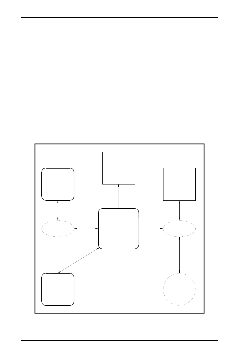
1.4 PanaCom ActiveX Software
Although the PanaView GUI is the component of the software package that
is visible to the user, it is really just one part of a sophisticated program.
Beneath the surface, PanaCom™ is seamlessly enabling the PC to
communicate with the GE instrument. Figure 1 illustrates the relationship
between the various components of the system.
As indicated, PanaCom not only interfaces with the standard PanaView
GUI, but it can be programmed to interact directly with customized versions
of PanaView or with OLE compliant Windows applications. In fact,
PanaCom is compatible with any process control/automation software that
supports ActiveX technology. For more information on PanaCom, contact
your GE sales engineer.
Figure 1: The PanaView/PanaCom System
PanaView™ Installation and Operation Manual 3
Page 18

Chapter 1. Features & Capabilities
1.5 Advanced Capabilities
In addition to the basic features described on page 1, PanaV iew of fers some
very useful advanced functionality:
• consult the comprehensive online help files to quickly answer questions
• use the supplied sample application (available separately, supplied only
with PanaCom software), visual basic code, and interactive
demonstrations as a guide for expanding the capabilities of the basic
program
Proceed to Chapter 2, Installation, to set up the system.
1.6 Windows Shortcuts
The instructions in this manual use the simple, direct approach to
accomplishing the desired tasks. That is, the use of the standard menus on
the menu bar is emphasized. However, as in any other conventional
Windows program, many tasks may be completed by alternate methods. For
example, a right mouse click or a keyboard shortcut may provide a more
convenient route to the desired result. Since these are standard Windows
procedures, they are covered in detail in the documentation that came with
your PC’s operating system and specific shortcut instructions are not
included in this manual.
1.7 Electronic Documentation
As an added convenience, an electronic version of this complete manual is
included on the PanaView installation CD-ROM. A file named
“PanaView.pdf” is included in the “Manual” directory on the CD-ROM.
This file is an Adobe Portable Document Format file, and it may be opened
with Adobe Acrobat Reader.
Acrobat Reader is a free application that may be downloaded from many
web sites, including the Adobe web site. The PDF file may be opened either
directly from the PanaView CD-ROM, or the file may be copied onto your
PC’s hard drive. Once opened, the electronic manual may be viewed on
your computer monitor and it may be printed in whole or in part.
4 PanaView™ Installation and Operation Manual
Page 19

Chapter 2. Installation
Chapter 2. Installation
2.1 Introduction
PanaView is supplied on a CD-ROM that includes the basic program, along
with sample applications and interactive demonstrations. The underlying
PanaCom ActiveX software is automatically installed during the PanaView
installation.
Before beginning the installation, make sure the personal comp uter system
meets the requirements listed in the next section.
2.2 Personal Computer Requirements
For optimum performance of the PanaV iew software, the personal computer
must meet the following minimum requirements:
• CD-ROM drive
• 300 MHz Pentium processor (CPU)
• 64 MB random access memory (RAM)
• 100 MB available hard drive space
• 32-bit Windows operating system (i.e., Windows NT 4.0 with Service
Pack 6 or higher, Windows 98SE/ME/2000/XP, or Windows 7)
• Internet Explorer 5.0 or higher installed
• VGA monitor and graphics card
To begin the installation, proceed to the next section.
PanaView™ Installation and Operation Manual 5
Page 20

Chapter 2. Installation
2.3 Software Installation
Note: If you have installed a software version of PanaView prior to version
1.3 on your PC, please go to Control Panel and uninstall the previous
version before installing the current version.
After verifying that the personal computer meets the minimum
requirements listed on page 5, proceed as follows:
1. Insert the PanaView CD-ROM into the CD-ROM drive.
2. Figure 2 below shows the first screen that appears, with three buttons
available. Click on:
• the [Install PanaView] button to continue the installation
• the [Browse the CD] button to examine the files, or
• the [Exit] button to close the screen.
Figure 2: Welcome Screen
6 PanaView™ Installation and Operation Manual
Page 21

Chapter 2. Installation
2.3 Software Installation (cont.)
3. The Install-Shield wizard, shown in Figure 3, will launch and guide you
through the installation process. Click on the
Note: If the Install-Shield wizard does not launch automatically, select
“Run” from the Windows Start menu and run the “Setup.exe” file in
the root directory of the CD-ROM.
[Next] button to continue.
Figure 3: Install-Shield Wizard
PanaView™ Installation and Operation Manual 7
Page 22
Chapter 2. Installation
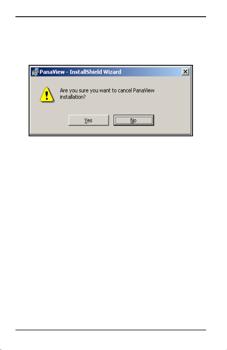
2.3.1 The [Back] and [Cancel] Buttons
If the [Cancel] button is chosen at any of the installation screens, the screen
shown in Figure 4 appears.
Figure 4: Cancel Installation Screen
At the screen shown above, the following two options are available:
• click the [No] button to return to the installation process, or
• click the [Yes] button to terminate the installation process and return to
Windows
On all but the first installation screen (where the
out), you may return to the previous installation screen to make corrections
by clicking on the
8 PanaView™ Installation and Operation Manual
[Back] button.
[Back] button is grayed
Page 23

Chapter 2. Installation
8
2.3 Software Installation (cont.)
4. Next, the End User Licence Agreement shown in Figure 5 appears.
Click the radio button for “I accept the terms in the licence agreement,”
and click on the
[Next] button to continue.
Figure 5: End User Licence Agreement
Note: A copy of this agreement begins on page iii of this manual.
PanaView™ Installation and Operation Manual 9
Page 24

Chapter 2. Installation
2.3 Software Installation (cont.)
5. Enter your name and your company name. Use the radio buttons to
select whether the application will be available to anyone using the
computer, or to the designated user only. Then, click on the
button to continue.
[Next]
Figure 6: User Information Screen
Proceed to Step 6 on page 11 to continue the installation.
10 PanaView™ Installation and Operation Manual
Page 25

Chapter 2. Installation
2.3 Software Installation (cont.)
6. Click on the [Next] button at the screen shown in Figure 7 to accept the
default directory for the PanaView files (recommended).
Note: To specify a different directory for the PanaView files, click on the
[Change] button and select the desired directory on your hard drive.
Figure 7: Choose Destination Location Screen
Proceed to Step 7 on page 12 to continue the installation.
PanaView™ Installation and Operation Manual 11
Page 26

Chapter 2. Installation
2.3 Software Installation (cont.)
7. At the screen shown in Figure 8, click the radio button for the type of
installation desired. The following three options are available:
Figure 8: Setup Type Screen
• Typical - the best choice for most installations (the recommended and
default choice)
• Minimal - install only the minimum required files (use if hard drive
space is a concern)
• Custom - allows the user to specify the files to be installed
(recommended for experienced users only)
If “Custom” was selected, follow the special instructions on page 13.
Otherwise, click on the
installation process on page 15.
12 PanaView™ Installation and Operation Manual
[Next] button and continue with Step 8 of the
Page 27

Chapter 2. Installation
2.3.1 Custom Setup
If “Custom” was selected at the “Setup Type” screen, proceed as follows:
a. Highlight either “Databases” or “Fonts” in the left pane of the
“Select Components” window in Figure 9.
Figure 9: Select Program Components
Continue the custom installation on the next page.
PanaView™ Installation and Operation Manual 13
Page 28

Chapter 2. Installation
2.3.1 Custom Setup (cont.)
b. Click on the icon to the left of the highlighted feature. A pop-up
menu appears, as shown in Figure 10.
Figure 10: Feature Installation Menu for Custom Setup
c. Click on the icon next to the installation prompt to determine how
PanaView will install a given feature. Four choices are available:
• The feature will be installed on the PC hard drive.
• The feature, and all subfeatures, will be installed on the PC hard
drive.
• The feature will be installed only when required.
• The feature will not be installed.
Click on the
installation.
14 PanaView™ Installation and Operation Manual
[Next] button and proceed to Step 8 on page 15 to continue the
Page 29

Chapter 2. Installation
2.3 Software Installation (cont.)
8. The screen shown in Figure 11 lists the entries made at the previous
screens. Press the
Note: Any of the prior entries may be edited by clicking on the [Back]
buttons until the desired screen reappears. This is the final chance to
change the listed settings.
[Next] button to begin installing the PanaView files.
Figure 11: Start Installation Screen
Proceed to Step 9 on page 16 to continue the installation.
PanaView™ Installation and Operation Manual 15
Page 30

Chapter 2. Installation
2.3 Software Installation (cont.)
9. When all of the PanaView files have been copied to your hard drive, the
screen shown in Figure 12 appears. Click on the
the InstallShield W iza rd .
[Finish] button to close
Figure 12: Setup Complete Screen
PanaView may be launched either by selecting PanaView from the
Windows S tart menu or by dou ble-clicking a PanaView shortcut (created by
the user) on the desktop.
Proceed to the next section to set up your hardware.
16 PanaView™ Installation and Operation Manual
Page 31

Chapter 2. Installation
2.4 Hardware Installation
After the PanaView software has been installed in accordance with the
instructions in the previous section, the system hardware must be properly
set up. To complete this task, the following items are required:
• a personal computer with PanaView installed and at least one available
serial port.
• a GE instrument that has been configured for use with PanaView and
which has an available serial port.
Note: Check with GE to make sure that your instrument is equipped with
the necessary hardwar e and software versions for PanaView
compatibility.
• for RS232 applications, a serial cable with the proper connectors for the
available serial ports (typically, this will be a cable with female DB9
connectors at both ends)
Note: The RS232 standard specifies a maximum cable length of 50 ft. For
longer cables, consult the factory for details.
PanaView™ Installation and Operation Manual 17
Page 32

Chapter 2. Installation
2.4.1 Installation Procedure
If all of the hardware requirements have been met, proceed as follows for
RS232 applications:
1. Set up the GE instrument in accordance with the instructions provided
in the User’s Manual supplied with the instrument.
2. Power down both the personal computer and the GE instrument.
CAUTION! Failure to power down both devices before proceeding to
the next step may cause damage to the personal
computer and/or the instrument.
3. Using the serial cable, connect the serial port on the personal computer
to the serial port on the instrument.
4. Power up the GE instrument and then the personal computer.
Your system is now ready to use the PanaView interface. Proceed to
Chapter 3, Initial Setup, for instructions on using the software.
18 PanaView™ Installation and Operation Manual
Page 33

Chapter 3. Initial Setup
Chapter 3. Initial Setup
3.1 Introduction
Before proceeding with this chapter, make sure that the PanaView software
has been installed in accordance with the instructions provided in Chapter 2,
Installation. Also, be certain that the personal computer has been restarted
since the completion of the installation procedure. Then, follow the
instructions below to perform the initial PanaView configuration.
3.2 Starting PanaView
The PanaView program may be launched from the Windows desktop in any
of the following conventional ways:
• use “My Computer” to navigate to the PanaView directory and
double-click on the PanaView.exe file
• use “Windows Explorer” to navigate to the PanaView directory and
double-click on the PanaView.exe file
• use the “Start Menu” to navigate to the PanaView listing and click on it
• double-click on a PanaView “Shortcut” that was created on the desktop
for this purpose.
Note: If necessary, consult your Windows documentation for detailed
instructions on any of the above procedures.
Proceed to the next section for instructions on completing the first-time
startup of PanaView.
PanaView™ Installation and Operation Manual 19
Page 34

Chapter 3. Initial Setup
3.3 First-Time Startup
Launch the PanaV iew program by one of the methods l isted on page 19, and
proceed as follows:
1. Notice the screen shown in Figure 13 below. The Version number of
your PanaView software, which may not be the same as the example in
Figure 3-1, is shown in this screen.
Figure 13: Initializing Screen
When PanaView is launched for the first time after installation, the
Note:
following directories are created:
C:\Program Files\PanaView\Logs
C:\Program Files\PanaView\Chart
These directories are used to store any Log or Chart (Graph) files
that are generated during your PanaView sessions.
20 PanaView™ Installation and Operation Manual
Page 35

Chapter 3. Initial Setup
3.3 First-Time Startup (cont.)
2. As shown in Figure 14, the default PanaView initial startup window
contains only the following basic components of the interface (listed
from top to bottom):
Note: To make the image in Figure 14 more readable on this page, the
window was compressed both vertically and horizontally from its
actual dimensions.
Figure 14: The Basic PanaView Window
• Title Bar - shows the PanaView name on the left side, and the
standard Windows control boxes on the right side
• Menu Bar - contains the File, Edit, View, Output, Window, and Help
menus on the left side
• Display Window - by default, is blank on initial startup
• Status Bar - by default on initial startup, shows status messages, date,
time, number of active logs, and number of communication errors
(from left to right)
For instructions on customizing the default startup window to make the
interface more useful, proceed to the next section.
PanaView™ Installation and Operation Manual 21
Page 36

Chapter 3. Initial Setup
3.4 The View Menu
Prior to setting up communications with a meter, the “View” menu (see
Figure 15) provides three options for customizing the PanaView interface:
• Comm Status (Off by default)
• Status Bar (On by default)
• Preferences
Note: The Refresh option in the View menu is not active at this time.
Figure 15: The View Menu
Access the “V iew” menu by clicking on it in the menu bar, and proceed to
the appropriate section for a discussion of the options listed above.
22 PanaView™ Installation and Operation Manual
Page 37

Chapter 3. Initial Setup
3.4.1 Comm Status
This option permits the user to toggle a communications status bar on and
off. The default state is “Off” as indicated by the absence of a check mark
in Figure 15 on page 22. When toggled “On”, the Comm Status bar appears
just above the main Status bar (see Figure 16) and displays the following
serial communications categories, from left to right:
Figure 16: The Comm Status Bar
To make the image in Figure 16 more readable on this page, the
Note:
window was compressed horizontally from its actual dimensions.
• Comm Stats: port number
• Queued
• Sent
• Rcvd
• Errs
Of course, all of the above categories will be empty, unless PanaView has
actively engaged in serial communications.
Note: The Comm Status bar reverts to its default “Off” state whenever
PanaView is closed.
PanaView™ Installation and Operation Manual 23
Page 38

Chapter 3. Initial Setup
3.4.2 Status Bar
The main Status bar shown on page 21 is always visible when PanaView is
first started. However, it may be toggled on and off at any time during a
PanaView session by selecting or deselecting it in the “View” menu. Its
current state is indicated by the absence or presence of a check mark to its
left.
The decision to turn the Status Bar “On” or “Off” is based on a balance
between information and display area. Turning the Status Bar “Off” creates
a larger display area, but the information displayed is no longer visible.
24 PanaView™ Installation and Operation Manual
Page 39

Chapter 3. Initial Setup
3.4.3 Preferences
To access the “Preferences” option (see Figure 15 on page 22), click on it
in the “View” menu. Click on any of the tabs and proceed to the appropriate
section for instructions.
Note: Within any of the tabs, click on the [Apply] button and then the [OK]
button to accept any changes and close the “Preferences” box. To
abort the process, click the
[Cancel] button instead.
3.4.3a Database Tab:
In the “Preferences” box, click the “Database” tab as shown in Figure 17
to display the currently used database files (*.mdb). If alternative files are
available from previous PanaView installations on the same computer or
from a PanaView installation on a different computer, the PanaView
database file or the Meter Configuration database file may be changed by
clicking on the button to the right of the appropriate text box.
Figure 17: The Database Tab
PanaView™ Installation and Operation Manual 25
Page 40

Chapter 3. Initial Setup
3.4.3 Preferences (cont.)
3.4.3b Grids Tab:
In the “Preferences” box, click the “Grids” tab as shown in Figure 18 to
display the current grid settings. The settings for either of the following
grids may be revised:
• For the Log Data Grid, the [Font], [Text Color], and [Background Color]
may be changed by clicking on the appropriate button(s). If a Default
Layout File (*.grx) has been created (as discussed in Chapter 6), it
may be loaded by clicking on the button to the right of that text box.
• For the Meter Browser Grid, the [Font], [Text Color], and [Background
Color]
may be changed by clicking on the appropriate button(s).
Figure 18: The Grids Tab
26 PanaView™ Installation and Operation Manual
Page 41

Chapter 3. Initial Setup
3.4.3 Preferences (cont.)
3.4.3c Text Display Tab:
In the “Preferences” box, click the “Text Display” tab as shown in
Figure 19 to display the current settings. The settings for either of the
following displays may be revised:
• For Graphing, the Default Configuration File is initially blank. If a
Default Configuration File (*.oc2) has been created, it may be loaded
by clicking on the button to the right of that text box.
• For Text, the [Background Color] and [Text Color] may be changed by
clicking on the appropriate option button(s).
Figure 19: The Text Display Tab
PanaView™ Installation and Operation Manual 27
Page 42
Chapter 3. Initial Setup
3.4.3 Preferences (cont.)
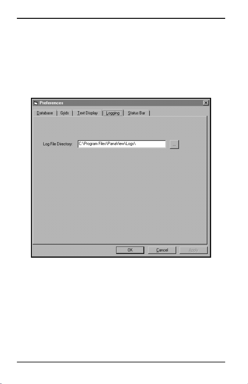
3.4.3d Logging Tab:
In the “Preferences” box, click the “Logging” tab as shown in Figure 20 to
display the Log File Directory. To specify a different directory for storing
log files, click on the button to the right of the text box.
Figure 20: The Logging Tab
28 PanaView™ Installation and Operation Manual
Page 43

Chapter 3. Initial Setup
3.4.3e Status Bar Tab:
In the “Preferences” box, click the “Status Bar” tab as shown in Figure 21
below to display the current settings. The settings for any of the following
items may be revised:
• The Font may be changed by clicking on the [Select Font] button and
specifying the new font, style and size.
• Check the selection box to display Status Messages or uncheck the
selection box to turn off Status Messages.
• Check the selection box to display the Date or uncheck the selection
box to turn off the Date. If the date is turned on, select the desired
date format from the drop down list box.
• Check the selection box to display the Time or uncheck the selection
box to turn off the Time. If the date is turned on, select the desired
time format from the drop down list box.
Figure 21: The Status Bar Tab
PanaView™ Installation and Operation Manual 29
Page 44

Chapter 3. Initial Setup
3.5 The Help Menu
The “Help” menu, which is the last item on the right of the menu bar (see
Figure 22), is the primary source of information regarding the PanaView
software and your PanaView installation. This menu contains the following
three options:
• Contents
• Search for Help On...
• About PanaVi ew
Figure 22: The Help Menu
Access the “Help” menu by clicking on it in the menu bar, and proceed to
the appropriate section for a discussion of the options listed above.
30 PanaView™ Installation and Operation Manual
Page 45

Chapter 3. Initial Setup
3.5.1 Contents
The “Contents” option lists all of the available PanaView general
information categories in the online help file in a format analogous to the
table of contents in a book. To access this information, simply click on the
“Contents” option and then click on the desired topic in the listing that
appears.
3.5.2 Search For Help On...
The “Search For Help On...” option lists all of the available PanaView
general information categories in the online help file in a format analogous
to the index in a book. To access this information, simply click on the
“Search For Help On...” option and then click on the desired topic in the
listing that appears.
Note: In some early versions of the PanaView software, the online help
functionality was not yet implemented. In such cases, attempts to
access the online help file generate the message shown in Figure 23.
Figure 23: Online Help Unavailable
If the message shown in Figure 23 appears upon clicking the “Contents” or
“Search For Help On...” option, online help is not available with your
version of PanaView. Simply click on the
[OK] button to return to the main
PanaView window.
PanaView™ Installation and Operation Manual 31
Page 46

Chapter 3. Initial Setup
3.5.3 About PanaView
The “About PanaView” option provides information on your version of the
software and about your personal computer system. To access this
information, simply click on the “About PanaView” option and the screen
shown in Figure 24 appears.
Figure 24: The About PanaView Screen
The screen in Figure 24 shows the version number of the currently installed
copy of PanaView, which may differ from the example shown here. To exit
the “Help” menu and return to the main PanaView window, simply click on
[OK] button. Otherwise, to examine the information relating to your
the
personal computer system, click on the
32 PanaView™ Installation and Operation Manual
[System Info...] button.
Page 47

Chapter 3. Initial Setup
3.6 Exiting PanaView
PanaView may be closed by any of the methods that are used for any other
standard Windows program. The two most common methods are:
• Click on “File” to open the file menu and then click on “Exit” to close
the program, or
• Click on the [X] control box on the right side of the title bar
Proceed to Chapter 4, Setting Up a Meter, to continue the setup of your
PanaView software.
PanaView™ Installation and Operation Manual 33
Page 48

Chapter 3. Initial Setup
[no content intended for this page]
34 PanaView™ Installation and Operation Manual
Page 49

Chapter 4. Setting Up a Meter
Chapter 4. Setting Up a Meter
4.1 Introduction
After your hardware and software have been installed as described in
Chapters 2 (Installation) and 3 (Initial Setup) of this manual and the
instrument’s User’ s Manual, the procedure for establishing communications
with a meter may be started. To set up a meter in PanaView, the following
steps must be completed in the order described in this chapter:
• open the “New Meter Browser” window (page 36)
• select the computer in the PanaView network tree (page 37)
• add a new communications port to the network (page 40)
• adding the new meter to the communication port (page 47)
Proceed to the next section to learn how PanaView connects to a GE
instrument.
PanaView™ Installation and Operation Manual 35
Page 50

Chapter 4. Setting Up a Meter
4.2 Opening the New Meter Browser
The first step in setting up a meter is to open the “New Meter Browser,”
which is located in the “File” menu. To accomplish this, click on the “File”
menu on the menu bar, and then click on the “New Meter Browser” option
(see Figure 25).
Figure 25: The File Menu
Proceed to the next section to select the computer name in the PanaView
network tree.
36 PanaView™ Installation and Operation Manual
Page 51

Chapter 4. Setting Up a Meter
4.2.1 The PanaView Network Tree
The “New Meter Browser” window consists of two panes:
• PanaView network tree pane on the left
• the details pane on the right
Figure 26 shows the initial appearance of the browser window. With the
network branch highlighted in the left pane, the computer name that was
specified during the installation procedure is listed in the right pane. Any
other computers that were installed on the network are also listed here.
Figure 26: The Network Branch
Note: The network tree works just like the directory tree that is used in
Wind ows Explorer. That is, if a branch has a “+” sign to its left, that
branch contains other branches. Just click on the “+” sign to expand
the branch and display those other branches. The “+” sign is then
replaced by a “-” sign. To collapse a branch with a “-” sign to its
left, just click on the “-” sign.
PanaView™ Installation and Operation Manual 37
Page 52

Chapter 4. Setting Up a Meter
4.2.1 The PanaView Network Tree (cont.)
With the “New Meter Browser” window open, complete the following
steps:
1. Expand the network branch by clicking on the “+” sign to its left. Then,
highlight the My Computer(Name) branch and the Meter Browser
window will look like Figure 27.
Figure 27: The My Computer Branch
Note: The right pane in Figure 27 lists all of the communication ports,
along with their configuration parameters, that are currently
assigned to the named computer. If this is the initial meter setup, the
list is empty.
38 PanaView™ Installation and Operation Manual
Page 53

Chapter 4. Setting Up a Meter
4.2.1 The PanaView Network Tree (cont.)
2. Fully expand the network tree by clicking on the “+” sign next to the
My Computer(Name) branch (see Figure 28).
Figure 28: The PC Logs Branch
Note: Step 3 is just included for reference, as PanaView’s logging featur e is
discussed in Chapter 6, Data Handling.
3. Click on the PC Logs branch and all available PC logs (and their
parameters) that have been created on the named computer are listed in
the details pane on the right. If no logs have yet been created, the details
pane is empty.
IMPORTANT: During initialization, PanaView cr eates special subdirectories
to store its log and chart (graph) files (see page 20). If these
subdirectories are removed, attempts to access the PC logs
will generate an error message.
4. Highlight the My Computer(Name) branch by clicking on it.
Proceed to the next section to add a communication port to the selected
computer.
PanaView™ Installation and Operation Manual 39
Page 54

Chapter 4. Setting Up a Meter
4.3 Adding a New Communication Port
Before a meter can be set up on the network, the serial communications port
to be used by that meter must be added to the PanaView network and
configured. To accomplish this, proceed as follows:
1. Open the “New Meter Browser” window and expand the network tree
as shown in Figure 28 on page 39. Then, highlight the My
Computer(Name) branch by clicking on it.
2. Pull down the “Edit” menu by clicking on it in the menu bar.
3. Click on the “New” menu option to select it, and a submenu opens with
two choices on it (see Figure 29).
Figure 29: The Edit Menu
Note: The only currently available option on th e “Edit” menu is “New.” The
other options become active only during relevant procedures.
40 PanaView™ Installation and Operation Manual
Page 55

Chapter 4. Setting Up a Meter
4.3 Adding a New Communication Port (cont.)
4. Click on the “Communications Port” option to select it (see Figure 29
on page 40). The dialog box shown in Figure 30 appears, with
“Untitled” as the default “Name.”
Figure 30: The Setup Communications Screen
The dialog box in Figure 30 permits the user to name the communication
port (“Comport” is used for this example) and to set up all of its
parameters.
IMPORTANT: During meter initialization, the baud rate specified above must
be the same as the baud rate of the meter.
PanaView™ Installation and Operation Manual 41
Page 56

Chapter 4. Setting Up a Meter
4.3 Adding a New Communication Port (cont.)
The following serial port parameters are available in the Setup
Communications dialog box:
CAUTION! Contact your GE representative before entering
communication port settings different from those of your
meter. Changing these settings may render your meter
inoperable and require reloading of the meter software.
Note: The “Name” and “Timeout (ms)” parameters must be entered
manually. All others are selected by clicking on the down arrow to
the right of the list box to drop down a list of available options.
• Port Number - select the number of the serial port on the PC
Default: depends on the PC’s specific hardware configuration
Options: depends on the PC’s specific hardware configuration
• Name - enter a name for the port (optional)
Default: Untitled
Options: enter any name that fits in the text box
• COM Port Type - select the type of serial port available
Default: RS232
®
Options: RS485HD, RS485FD, IrDA
IMPORTANT: If you select TCP/IP, the menu changes. Proceed to page 45.
42 PanaView™ Installation and Operation Manual
, IR232®, TCP/IP (Ethernet)
Page 57

Chapter 4. Setting Up a Meter
4.3 Adding a New Communication Port (cont.)
Note: For infrared applications, IR232 generally provides better
performance than IrDA. If you select IR232, you must disable the
drivers in the infrared device connected to your PC for the device to
work with PanaView. From the Control Panel, click on the System
icon, and then on the Hardware tab. Click on Device Manager, and
then on the specific infrared device listed under Infrared Devices.
Finally, cl ick on Disable to disable the device drivers.
• Baud Rate - select the data transfer speed to be used
Default: 19200 Baud
Options: 300, 600, 1200, 2400, 4800, 9600, 19200, 38400, 57600,
115200, 128000, 230400
Note: A baud rate of 19,200 is sufficient for almost all applications. If you
experience periodic communication reliability problems, you may
wish to consider lowering the baud rate on your instrument and in
PanaView.
• Parity - select the parity setting to be used
Default: None
Options: Even, Mark, None, Odd, Space
• Handshaking - select the type of handshaking protocols used
Default: No Handshaking
Options: No Handshaking, XON/XOFF, RTS/CTS, RTS and
XON/XOFF
• Data Bits - select the number of data bits in a word
Default: 8 Data Bits
Options: 7 Data Bits, 8 Data Bits
• Stop Bits - select the number of stop bits in a word
Default: 1 Bit
Options: 1 Bit, 2 Bits
PanaView™ Installation and Operation Manual 43
Page 58

Chapter 4. Setting Up a Meter
4.3 Adding a New Communication Port (cont.)
• Timeout (ms) - enter the time interval that must pass before a
communications attempt is aborted
Default: 3000
Options: keep the default value unless instructed otherwise
IMPORTANT: Remember that the choices made above must match those that
were made in setting up the meter’s serial port.
5. After all of the communications port parameters have been set, click the
[OK] button (see Figure 30 on page 41).
Note: To abort the addition of the communications port, click on the
[Cancel] button instead of the [Apply] button.
6. Wait a few seconds for the information to be processed and registered
(the option buttons are greyed out during this period). When the
button becomes active again, click on it to complete the process.
Proceed to page 47 to set up a new meter on the newly installed
communication port.
[OK]
44 PanaView™ Installation and Operation Manual
Page 59

Chapter 4. Setting Up a Meter
4.3.1 Setting up Ethernet Communications
If you have selected TCP/IP in step 4 on page 42, the Setup
Communications window appears similar to Figure 31.
Figure 31: Setup Communications for TCP/IP
1. Type in the desired Name and Timeout (in milliseconds).
2. In the IP Address text box, enter the IP (MAC) address supplied with
customer documentation. In the Port Number box, enter the port
number supplied with customer documentation. (The default number is
2101.)
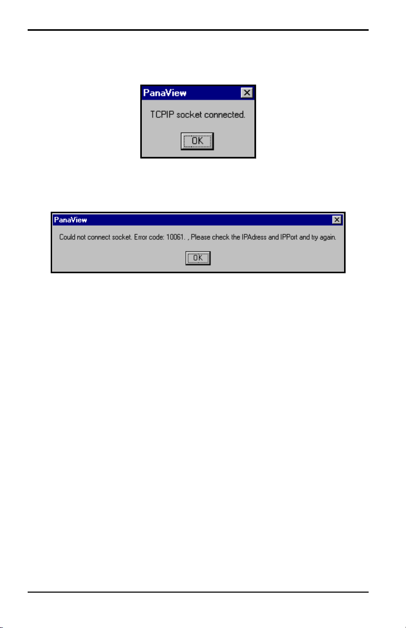
3. Click [OK] to complete data entry. If the connection is successful, a
screen appears similar to Figure 32 on page 46.
PanaView™ Installation and Operation Manual 45
Page 60
Chapter 4. Setting Up a Meter
4.3.1 Setting up Ethernet Communications (cont.)
Figure 32: Successful TCP/IP Connection Screen
If the connection is unsuccessful, a screen similar to Figure 33 appears.
Figure 33: Unsuccessful TCP/IP Connection Screen
46 PanaView™ Installation and Operation Manual
Page 61

Chapter 4. Setting Up a Meter
4.4 Adding the First New Meter
A meter may be set up on any communications port that has been added to
the network in accordance with the procedures in the previous section.
Note: If you are using PanaView software version 1.4.6 or greater, the
communication connection is made automatically using IrOBEX (IR
Object Exchange).
For earlier software versions, to manually add the first new meter to the
PanaView network, proceed as follows:
1. Notice in Figure 34 that the network tree now has the newly configured
communication port listed.
Figure 34: The New Serial Port Branch
Note: In this example, the communication port has been named “Untitled”
and is located on COM2. Whatever name was entered in the setup
process appears.
2. Highlight the communication port to which the meter will be added by
clicking on it, and then open the “Edit” menu on the menu bar (if the
communication port is not highlighted first, the “New Meter” option is
not active in the “Edit” menu).
PanaView™ Installation and Operation Manual 47
Page 62

Chapter 4. Setting Up a Meter
4.4 Adding the First New Meter (cont.)
3. Click on the “New” option in the “Edit” menu (refer to Figure 35).
4. Click on the “Meter” menu option.
Figure 35: The Edit Menu
Continue with Step 5 on the next page.
48 PanaView™ Installation and Operation Manual
Page 63

Chapter 4. Setting Up a Meter
4.4 Adding the First New Meter (cont.)
5. After selecting the “New” and “Meter” options, the dialog box shown
in Figure 36 appears. Select the “I don’t know the node ID of the meter I
am adding to the network” radio button and then click o n the
option button.
Note: When installing the first meter on the network, even if you know the
node ID assigned to the meter, it is more foolproof to allow PanaView
to retrieve the information directly from the meter. If the “I know the
node ID of the meter I am adding to the network.” option is selected
instead, the process skips directly to Step 8 on page 52.
[OK]
Figure 36: The Node ID Dialog Box
Continue with Step 6 on the next page.
PanaView™ Installation and Operation Manual 49
Page 64

Chapter 4. Setting Up a Meter
4.4 Adding the First New Meter (cont.)
6. After responding to the previous dialog box, the dialog box shown in
Figure 37 appears. In most instances, users connect their PC to one
instrument only via a direct serial cable. Therefore, select the “It is the
only meter connected to the communication port” radio button and then
click on the
[OK] option button.
Figure 37: The Only Meter Dialog Box
Continue with Step 7 on the next page.
50 PanaView™ Installation and Operation Manual
Page 65

Chapter 4. Setting Up a Meter
4.4 Adding the First New Meter (cont.)
7. After responding to the previous dialog box, a dialog box showing the
Node ID (16 in this example) of the meter appears (see Figure 38).
Select the “I wish to use this Node ID” radio button and then click on
[OK] option button.
the
Note: PanaView gets this Node ID directly from the meter; do not use a
different Node ID for a single-meter setup.
Figure 38: Node ID Confirmation
Figure 39: Confirmation Dialog Box
PanaView™ Installation and Operation Manual 51
Page 66

Chapter 4. Setting Up a Meter
4.4 Adding the First New Meter (cont.)
8. At the dialog box shown in Figure 39 o n p age 51, click on the [OK]
option button to add the meter and configure it. The dialog box shown
in Figure 40 appears.
Figure 40: The Add Meter Dialog Box
9. In the dialog box above, enter a name for the new meter. The Node ID
and Meter Communication Parameters have been entered automatically
by PanaV iew . In addition, PanaView populates certain other fields, such
as “Model Name,” “Firmware Version,” and “PCI Order Number” with
data retrieved from the GE instrument. Click on the
[OK] option button
to initialize the new meter.
52 PanaView™ Installation and Operation Manual
Page 67

Chapter 4. Setting Up a Meter
4.4 Adding the First New Meter (cont.)
After completing Step 9 on page 52, do not make any inputs with either the
mouse or the keyboard until the new meter initialization process is
completed. While the meter is initializing, the information shown in
Figure 41 is added to the new meter dialog box.
Figure 41: The Initialization Screen
Note: The “Clock” text box has been filled in with the current date and
time, the meter data (an IGM in this example) has been added, and
the active communications status is being displayed along the bottom
of the dialog box.
PanaView™ Installation and Operation Manual 53
Page 68

Chapter 4. Setting Up a Meter
4.4 Adding the First New Meter (cont.)
After the initialization has been completed, PanaView adds the new meter
to the PanaView network tree and automatically closes the “Add New
Meter” dialog box (see Figure 42).
Figure 42: The Updated Network Tree
Note: A GE GN868 flowmeter was used for this example, as is indicated in
Figure 42. The information sh own in the right pane in Figure 42 and
the branches available under the “New Meter” branch in the left
pane of the window will reflect the specific meter that was actually
installed.
This completes the set up of the first new meter in PanaView. Proceed to
Chapter 5, Running PanaView, for information on using the PanaView
interface to communicate with the attached meter. Otherwise, continue with
the next section to install an additional meter.
54 PanaView™ Installation and Operation Manual
Page 69

Chapter 4. Setting Up a Meter
4.5 Adding an Additional Meter
An additional meter may be added to the PanaView network at any time in
either of the following situations:
• replace the existing meter with a different one (see below)
• keep the existing meter and add an additional meter (see the next page)
If more than one IrDA meter will be used with one instance of PanaV iew, be
sure to manually disconnect a meter and remove it from the startup
connection list before breaking the connection and connecting another
meter.
Note: If an IrDA meter is not disconnected and removed from the “startup
connection list,” a meter of a different serial number will display
with the ID of the first meter.
Proceed to the appropriate section for specific instructions.
4.5.1 Replace the Existing Meter
To replace a meter that is already installed on the PanaView network with a
different meter on the same communication port, complete the following
steps:
1. Remove the existing meter from the network, as described in the
“Removing the Meter” section on page 68.
2. Remove the existing communication port from the network, as
described in the “Removing the Communication Port” section on
page 62.
3. Add the communication port back onto the network by following the
instructions in the “Adding a New Communication Port” section on
page 40.
4. Add the replacement meter by following the instructions in the “Adding
the First New Meter” section on page 47.
Note: Failure to remove the old meter and/or communication port first may
result in some of the old meter’s properties (such as the name) being
assigned to the new meter.
PanaView™ Installation and Operation Manual 55
Page 70

Chapter 4. Setting Up a Meter
4.5.2 Keep the Existing Meter
To keep the existing meter and add an additional meter to a different
communication port, complete the following steps:
1. Add the new communications port to the PanaView network by
following the instructions that begin on page 40.
2. Determine the Node ID of the second meter. Consult the User’s Manual
for the meter for instructions on finding the assigned Node ID in the
meter’s menu system.
3. Change the Node ID of the existing meter to any value between 16 and
99 that is different from that of the new meter. Refer to “Editing the
Meter Settings” on page 65 for specific instructions.
IMPORTANT: The new communication port must be different from the one to
which the existing meter is already attached.
4. Add the new meter to the new communication port by following the
instructions that begin on page 47, with one exception:
a. At the Node ID dialog box (see Figure 36 on page 49), select the “I
know the node ID of the meter I am adding to the network” option
and click on the
b. When you reach the dialog box shown in Figure 40 on page 52, enter
[OK] option button.
the known Node ID for the second meter.
c. Click on the [Set Node ID] option button to register the entered value,
and then click on the
[OK] option button to complete the process.
The PanaView network tree will now show two attached communication
ports with one meter attached to each port.
56 PanaView™ Installation and Operation Manual
Page 71

Chapter 5. Running PanaView
Chapter 5. Running PanaView
5.1 Introduction
After at least one meter has been added to the PanaView network in
accordance with the instructions in Chapter 4, Setting Up a Meter, the many
interactive features in the PanaView interface may be accessed. To navigate
through the PanaView program, refer to the menu map on page 104. If it is
not already running, launch PanaView. A screen like the one shown in
Figure 43 below appears (the exact PanaView version number and meter
details will reflect your specific installation):
Figure 43: The Bootup Screen
With some meters, the bootup screen displays the meter model, serial port,
and node ID during the initialization process. In these cases, a progress bar
across the bottom of the screen indicates the percentage of the initialization
that has been completed.
PanaView™ Installation and Operation Manual 57
Page 72

Chapter 5. Running PanaView
5.2 Initialization Error
If the meter is not turned on before launching PanaView, the attempt to
initialize the meter will fail, and the dialog box shown in Figure 44 appears.
To recover from the failed initialization attempt, complete the procedure
below.
Figure 44: Communication Error Dialog Box
At the screen shown in Figure 44, choose one of the following four options:
• click on the [Exit Application] option button to close PanaView, or
• select the “Delete Meter” radio button and click on the [OK] option
button to permanently remove the meter from the PanaV iew network,
or
• select the “Don’t Load Meter (this se ssion only)” radio button and
click on the
PanaView network for this session only, or
[OK] option button to remove the meter from the
• select the “T ry to initialize the meter again” radio button and click on
the
[OK] option button to try again to communicate with the meter.
Determine the cause of the failed communication attempt (often a loose
serial cable), correct the problem, and try again.
58 PanaView™ Installation and Operation Manual
Page 73

Chapter 5. Running PanaView
5.3 Communication Port Settings
During the initial addition of a communication port to the PanaView
network, various port parameters were specified. If it ever becomes
necessary or desirable to change any of these settings, this is easily
accomplished as follows:
Note: T asks that were described in detail in previous chapters, such as how
to open a particular menu, are simply stated without details in this
chapter.
1. Open the “New Meter Browser” from the “File” menu.
2. Fully expand the network tree and highlight the chosen communication
port (see Figure 45).
Figure 45: The Serial Port Branch
PanaView™ Installation and Operation Manual 59
Page 74

Chapter 5. Running PanaView
5.3 Communication Port Settings (cont.)
3. With the desired communication port highlighted, open the edit menu
as shown in Figure 46.
Figure 46: The Edit Menu
There are now three available options on the “Edit” menu:
• New - this was discussed in Chapter 4, Setting Up a Meter
• Properties - use to edit the current port settings
• Remove - use to delete the port from the PanaView network
IMPORTANT: The PC’s port parameters must be identical to those
programmed into the meter’s serial port, as described in the
meter’s User’s Manual.
Proceed to the appropriate section for a discussion of the “Properties” (see
page 61) and “Remove” (see page 62) options.
60 PanaView™ Installation and Operation Manual
Page 75

Chapter 5. Running PanaView
5.3.1 Editing the Communication Port Settings
To edit the current settings for a communication port, complete the
following steps:
1. From the “Edit” menu shown in Figure 46 on page 60, click on the
“Properties” option. The dialog box shown in Figure 47 appears.
Figure 47: Communication Port Settings
2. See page 45 in Chapter 4, Setting Up a Meter, for instructions on
choosing the communication port parameters.
3. When all of the desired changes have b een made to the parameter
settings, click on the
PanaView™ Installation and Operation Manual 61
[OK] option button.
Page 76

Chapter 5. Running PanaView
5.3.2 Removing the Communication Port
T o remove a communication port from the PanaView network, complete the
following steps:
1. From the “Edit” menu shown in Figure 46 on page 60, click on the
“Remove” option. The dialog box shown in Figure 48 appears.
Figure 48: Port Removal Confirmation
2. Click on the [Yes] option button to remove the selected port (and all of
its attached meters) from the PanaView network, or click on the
option button to abort the operation.
[No]
After responding to the above prompt, you are returned to the “New Meter
Browser” window.
62 PanaView™ Installation and Operation Manual
Page 77

Chapter 5. Running PanaView
5.4 Meter Configuration Settings
During the initial addition of a meter to the PanaView network, various
settings were specified. If it ever becomes necessary or desirable to change
any of these settings, this is easily accomplished as follows:
Note: T asks that were described in detail in previous chapters, such as how
to open a particular menu, are simply stated without details in this
chapter.
1. Open the “New Meter Browser” from the “File” menu.
2. Fully expand the network tree and highlight the chosen meter (see
Figure 49).
Figure 49: The Meter Branch
PanaView™ Installation and Operation Manual 63
Page 78

Chapter 5. Running PanaView
5.4 Meter Configuration Settings (cont.)
3. With the desired meter highlighted, open the “Edit” menu as shown in
Figure 50.
Figure 50: The Edit Menu
There are three available options on the “Edit” menu:
• New - this was discussed in Chapter 4, Setting Up a Meter
• Properties - use to edit the current settings
• Remove - use to delete the meter from the PanaView network
Proceed to the appropriate section for a discussion of the “Properties” (see
the next page) and “Remove” (page 68) options.
64 PanaView™ Installation and Operation Manual
Page 79

Chapter 5. Running PanaView
5.4.1 Editing the Meter Settings
To edit the current settings for a meter, complete the following steps:
1. From the “Edit” menu shown in Figure 50 on page 64, click on the
“Properties” option. The dialog box shown in Figure 51 appears.
Figure 51: Meter Settings
2. The meter name may be edited directly in the text box shown.
3. Some meters have an Auto Cal Interval (the time between automatic
calibration sequences), which may be edited directly in the text box.
PanaView™ Installation and Operation Manual 65
Page 80

Chapter 5. Running PanaView
5.4.1 Editing the Meter Settings (cont.)
4. The meter’s Time may be reset in three different ways:
• manually enter the time and date in the text box, or
• click on the [Sync to PC] option button to have PanaView set the time
and date to the current PC setting, or
• click on the [Set] option button to open the dialog box shown in
Figure 52. Set the desired date and time as indicated, and click on the
[OK] option button.
Figure 52: The Date/Time Dialog Box
66 PanaView™ Installation and Operation Manual
Page 81

Chapter 5. Running PanaView
5.4.1 Editing the Meter Settings (cont.)
IMPORTANT: Never change a meter’s Node ID to the same value as another
meter on the same PanaView network. Also, Node ID values
below 16 are not accepted by PanaView.
5. The Node ID may be reset in three different ways:
• manually edit the Master ID, Node ID and (Meter) ID values in the
text boxes, or
• click on the [Set Node ID] option button to have PanaView reinitialize
the meter, or
• click on the [Get Node ID] option button to begin the node ID setup
sequence described on page 47 of Chapter 4, Setting Up a Meter.
6. Four of the Meter Communication Parameters may be edited by
selecting one of the alternate choices in the list boxes shown in
Figure 51 on page 65. See page 47 in Chapter 4, Setting Up a Meter, for
a discussion of these parameters and the available options.
IMPORTANT: The PC’s port parameters must be identical to those
programmed into the meter’s serial port.
PanaView™ Installation and Operation Manual 67
Page 82

Chapter 5. Running PanaView
5.4.2 Removing the Meter
To remove a meter from the PanaView network, complete the following
steps:
1. From the “Edit” menu shown in Figure 51 on page 65, click on the
“Remove” option. The dialog box in Figure 53 below appears.
Figure 53: Meter Removal Confirmation
2. Click the [Yes] option button to remove the selected meter from the
PanaView network, or click on the
operation.
[No] option button to abort the
After responding to the above prompt, you are returned to the “New Meter
Browser” window.
68 PanaView™ Installation and Operation Manual
Page 83

Chapter 5. Running PanaView
5.5 Multiple PanaView Windows
For convenience in monitoring outputs from multiple meters or multiple
outputs from a single meter, PanaVi ew has been designed to permit the
simultaneous display of more than one output window. To accomplish this,
proceed as follows:
Note: As an example we will open and arrange both a “Meter Browser”
window and a “Text Display” window.
1. Launch PanaView and pull down the “File” menu.
2. Click on the “New Meter Browser” option (see Figure 25 on page 36)
to configure a screen like that shown in Figure 39 on page 51.
3. Pull down the “Output” menu and click on the “Text Display” option
(this menu is discussed in detail in Chapter 6, Data Handling). A
window similar to Figure 57 on page 75 is opened and stacked on top of
the previously visible “Meter Browser” window.
4. To rearrange the two open windows, pull down the “Window” menu
(see Figure 54).
Figure 54: The Window Menu
PanaView™ Installation and Operation Manual 69
Page 84

Chapter 5. Running PanaView
5.5 Multiple PanaView Windows (cont.)
The PanaV iew “Window” menu is identical to that in any other Windows
application. That is, the entries below the divider line represent all of the
currently open windows, with the active window having a check mark next
to its name. In the example shown in Figure 55 on page 71, notice that the
“Meter Browser” and “Text Display” windows are open, with the “Text
Display” window marked as the active window.
There are four methods, which are consistent with standard Windows
conventions, available for manipulating the two open windows (the Tile
Output Displays option is discussed in Chapter 6, Data Handling):
Note: For a detailed discussion on using the “Window” menu, refer to any
Microsoft Windows manual.
• make a window active and maximized in size by clicking on its Name, or
• show both windows in an overlay format by clicking on Cascade, or
• show both windows, with each taking up one half of the screen height,
by clicking on Tile Horizontal, or
• show both windows, with each taking up one half of the screen width, by
clicking on Tile Vertical.
As an example, the currently open “Meter Browser” and “Text Display”
windows used for this discussion are shown in the “Tile Horizontal” format
in Figure 55 on page 71, with the “Text Display” window as the active
window.
Note: In any of the display modes, only one window can be active at any
given time. To make another window active, simply click anywhere in
its title bar.
70 PanaView™ Installation and Operation Manual
Page 85

Chapter 5. Running PanaView
Figure 55: Horizontally Tiled Windows
PanaView™ Installation and Operation Manual 71
Page 86

Chapter 5. Running PanaView
[no content intended for this page]
72 PanaView™ Installation and Operation Manual
Page 87

Chapter 6. Data Handling
Chapter 6. Data Handling
6.1 Introduction
After PanaView has been installed and configured in accordance with the
instructions given in the first five chapters of this manual, you are ready to
begin using PanaView to view, manipulate and save data information. To
illustrate the process, we will assume that neither the GE instrument nor the
PanaView software is currently running.
6.2 Preparing to Work with Data
To begin working with data, complete the following steps:
1. Power up the meter and wait until it has initialized and is displaying its
normal default screen.
2. Launch PanaView and wait until it initializes the meter (see Figure 43
on page 57) and displays the basic PanaView window (see Figure 14 on
page 21).
3. As described in Chapter 5, Running PanaView, open the “Meter
Browser” window and highlight the meter to be used.
At this time, any of PanaView’s comprehensive data handling capabilities
may be used. These include:
• collecting and displaying live data in text format
• collecting and displaying live data in graphical format
• collecting and logging live data
• displaying a log file in text format
• displaying a log file in graphical format
PanaView™ Installation and Operation Manual 73
Page 88

Chapter 6. Data Handling
6.2 Preparing to Work with Data (cont.)
T o access PanaV iew’ s data handling options, pull down the “Output” menu,
as shown in Figure 56 below.
Figure 56: The Output Menu
IMPORTANT: This manual only provides an overview of the general data
handling procedures. Since each instrument has its own
unique user interface, see the instrument’s User’s Manual for
information specific to your particular instrument.
Proceed directly to the appropriate section for instructions on each of the
following output options:
• Text Display output on page 75
• Graphing output on page 78
• Logging output on page 88
74 PanaView™ Installation and Operation Manual
Page 89

Chapter 6. Data Handling
6.3 The Text Display Output
T o collect data from the instrument and display it on a text screen, complete
the following steps:
1. Complete Steps 1-3 on page 73.
2. Pull down the “Output” menu and click on the “Text Display” option
(see Figure 56 on page 74).
Note: The “Text Display” window that appears after Step 2 is actually
stacked on top of any previously opened windows (such as the “Meter
Browser” window).
3. Using the “Window” menu, as described on page 69, arrange the open
windows in the desired format. For this discussion, Figure 57 shows the
“Text Display” window in its maximized (full-screen) size.
Figure 57: The Text Display Window
Note: Figure 57 has been compressed both vertically and horizontally for
improved clarity.
4. The left pane of the “Text Display” window contains the standard
PanaView network tree. Expand this tree as far as necessary , and double
click on the desired process parameter to display it in the right pane of
the window.
PanaView™ Installation and Operation Manual 75
Page 90

Chapter 6. Data Handling
6.3 The Text Display Output (cont.)
Note: Refer to your instrument’s User’s Manual for details on selecting a
display parameter and the appearance of the “Text Display” window
for your specific meter.
5. Before actual data values can be displayed in the text pane, activate one
of the following data collection modes (see Figure 57 on page 75):
• Click on the [Get Once] option button at the bottom of the right pane
in the “Text Display” window. The current value of the selected
process parameter, as specified in the PanaView network tree, is
displayed in the right pane of the “Text Display” window.
or
• Enter an “interval” in the text box at the bottom of the right pane in
the “Text Display” window, or check the “Max. Comm Rate” box to
collect readings as fast as the system allows (1 sec). Then, click on the
[Continuous] option button to begin collecting data for display in the
right pane of the “Text Display” window.
Note: Any value entered in the “Interval” text box is overridden if the “Max.
Comm Rate” box is checked.
6. If the [Continuous] option was selected in Step 5 above, click on the
[Stop] option button, which has replaced the original [Continuous] option
button, to terminate data collection.
The “Text Display” window may be left open while other tasks are
performed, or it may be closed by clicking on the lower
[X] control button at
the far right of the menu bar.
IMPORTANT: If you click on the upper [X] control button at the far right of
the PanaView title bar, you will exit PanaView completely.
76 PanaView™ Installation and Operation Manual
Page 91

Chapter 6. Data Handling
Displaying Multiple Process Parameters
The procedure for displaying a single process parameter in a text screen
may be repeated to simultaneously display multiple process parameters. To
do so, proceed as follows:
1. Display the first process parameter in a text screen, as described in the
previous section.
2. Repeat Step 1 for any desired additional process parameters, by double
clicking on them in the PanaView network tree. PanaView
automatically tiles the multiple text screens in the right pane of the
“Text Display” window.
3. As in any standard Windows application, the multiple text screens may
be resized by dragging their borders. Also, the individual panes within a
parameter’s text screen may be resized by dragging the borders within
that text screen.
4. To close an open text screen, right click anywhere within that screen
(except in the title bar or the error section) and click on the
option that pops up in the context menu.
[Remove]
Note: After resizing or removing any of the multiple text scr eens, the default
tiled layout may be restored by opening the “Window” menu (see
Figure 54 on page 69) and clicking on the “Tile Output Displays”
option.
6.3.1 Displaying Multiple Text Windows
The procedures for displaying one or more process parameters in a single
“Text Display” window may be repeated to open multiple “Text Display”
windows. To do so, proceed as follows:
1. To open another “Text Display” window, repeat the steps on page 75
and page 76.
2. To display the desired process parameter(s) in the new window, repeat
Steps 1-4 above.
3. Arrange the multiple “Text Di splay” windows as desired via the
“Window” menu (see Figure 54 on page 69).
PanaView™ Installation and Operation Manual 77
Page 92

Chapter 6. Data Handling
6.4 The Graphing Output
To collect data from the instrument and display it graphically in a new
format, complete the following steps:
6.4.1 Setting Up a Graph
1. Perform Steps 1-3 on page 73.
2. Pull down the “Output” menu and click on the “Graphing - New”
option (see Figure 56 on page 74).
Note: The “Graph” window is stacked on top of any previously opened
windows (such as the “Meter Browser” window).
3. Using the “Window” menu, as described on page 69, arrange the open
windows in the desired format. For this discussion, Figure 58 shows the
“Graph” window in its maximized (full-screen) size.
Figure 58: The Graph Window
78 PanaView™ Installation and Operation Manual
Page 93

Chapter 6. Data Handling
6.4.1 Setting Up a Graph (cont.)
The “Graph” window shown on the previous page consists of three panes:
• left pane - PanaView network tree
• top right pane - graph with default chart style
• bottom right pane - graph controls or text display
Note: The three panes of the “Graph” window may be resized by simply
dragging their borders.
6.4.2 Graphing Data
The PanaView network tree has already been described, and the display
pane shows only a graph in the default style with no data points. Thus, we
need only discuss the use of the bottom right pane. To begin graphing your
data, proceed as follows:
1. Expand the network tree as far as necessary and double click on the
process parameter to be graphed. The grid for the selected graph
appears in the display pane, with “Time” as the x-axis and the
parameter “Value” as the y-axis. In addition, a legend appears above
the graph, which indicates the name, data point shape and line color for
that parameter.
2. If desired, a second parameter may be added to the graph by repeating
Step 1. In this case, the parameter “Value” is shown as a right y-axis
(Y2).
Note: Although only two parameters may be graphed for any one meter
channel, the same two parameters may also be graphed for any other
active meter channels.
3. To begin plotting data for the selected parameter(s), enter a time
“Interval” for data sampling in the text box provided (the default value
is 5 seconds).
4. Click on the [Plot Continuous] control button to begin graphing the
selected process parameter(s) as a function of time, at the interval
specified in Step 3.
PanaView™ Installation and Operation Manual 79
Page 94

Chapter 6. Data Handling
6.4.2 Graphing Data (cont.)
5. While PanaView is graphing the data, the following actions may be
taken from the control pane:
• change the sampling interval by entering a new value
• click on the [Zoom Out] control button to increase the size of the
intervals shown on the x-axis
• click on the [Zoom In] control button to decrease the size of the
intervals shown on the x-axis
Note: The zoom buttons may be clicked multiple times to enhance the effect.
• click on the “Text Display” tab to view the data being graphed in the
text format described in the previous section
6. When you have finished graphing your data, click on the [Stop] control
button, which has replaced the original
[Plot Continuous] control button.
6.4.3 Setting the Graph Properties
To permit customization of a graph’s appearance, PanaView has a
comprehensive “2D Chart Control Properties” feature. To access this
feature, right click on the graph to open the dialog box shown in Figure 59.
The chart (graph) properties available using this dialog box are listed in
Table 1 on page 82.
Figure 59: Chart Properties Dialog Box
80 PanaView™ Installation and Operation Manual
Page 95

Chapter 6. Data Handling
6.4.3 Setting the Graph Properties (cont.)
Any property change made by selecting an item from a list box
automatically appears on the graph. However, changes made to a value in a
text box do not take effect until you click on the
close the “Chart Properties” dialog box and return to the “Graph”
window, click on the
Note: You may click on the [Cancel] option button at any time to keep all of
[OK] option button.
the original graph properties.
The options available on the seven tabs in the “Chart Properties” dialog
box are easy to use. However, a detailed description of each property may
be accessed by clicking on the
[Help] option button to activate the “2D
Chart OCX User’s Help -- v5.0” shown in Figure 60. Refer to any standard
Windows manual for instructions on using this online hel p feature. To close
the online help window, click on the
[X] control bottom at the upper right
corner.
[Apply] option button. To
Figure 60: Chart Properties Help File
PanaView™ Installation and Operation Manual 81
Page 96

Chapter 6. Data Handling
6.4.3 Setting the Graph Properties (cont.)
Table 1: Chart (Graph) Properties
Main Tab Sub-Tab Comments
Border
Control
Axes
Chart Styles
Titles
Legend
Chart Area
Plot Area General
Interior
General X, Y, and Y2 axes may be
Annotation
Scale
Title
Grid
Grid Style
Font
Line Style Style names may be added to
Symbol Style
General Header and Footer may be
Label
Location
Border
Interior
Font
General
Location
Border
Interior
Font
General Set interior background color
Location
Border
Interior
independently configured.
or removed from list.
independently configured.
to white before printing
graph.
82 PanaView™ Installation and Operation Manual
Page 97

Chapter 6. Data Handling
6.4.4 Creating Chart Templates
After setting up a chart (graph) as described in the previous section, you
will find that several new menu options are now available in the “File”
menu (see Figure 61).
Figure 61: The File Menu for Graphs
Use the new “File” menu options as follows:
• Click on the “Print” menu option to open the standard Windows
print dialog box. This allows you to print out a copy of the current
graph.
Note: For a more legible printout, make sure the graph has black text on a
white background (see page 80).
• Click on the “Save As” menu option to save the data collected during
the graphing process as a log file. The dialog box shown in Figure 62
on page 84 appears. Enter a name for the log file and click on the
option button to save the file as
C:\Program Files\PanaView\Logs\Untitled.LOG.
PanaView™ Installation and Operation Manual 83
[OK]
Page 98

Chapter 6. Data Handling
6.4.4 Creating Chart Templates (cont.)
Figure 62: The Save As Dialog Box
• Click on the “Save Output T emplate” menu option to save the current
graph properties and the parameters to be graphed as a template to be
used for future graphs. The dialog box shown in Figure 63 appears.
Enter a name for the chart (graph) template file and click on the
[Save] option button to save the file as
C:\Program Files\PanaView\Charts\Untitled.opt.
Figure 63: The Save Output Template Dialog Box
84 PanaView™ Installation and Operation Manual
Page 99

Chapter 6. Data Handling
6.4.4 Creating Chart Templates (cont.)
Note: The following menu option only becomes active after clicking on the
[Clear Data] option button to delete the data points from the current
graph.
• Click on the “Save Chart Styl e” menu option to save only the current
graph properties (and not the parameters to be graphed) as a template
to be used for future graphs. The dialog box shown in Figure 64
appears. Enter a name for the chart (graph) template file and click on
the
[Save] option button to save the file as
C:\Program Files\PanaView\Charts\Untitled.opt.oc2.
Figure 64: The Save Chart Style Dialog Box
IMPORTANT: Remember that the “Save Chart Style” option saves only the
graph properties, while the “Save Output Template” option
saves both the graph properties and the parameters to be
graphed.
PanaView™ Installation and Operation Manual 85
Page 100

Chapter 6. Data Handling
6.4.5 Using Chart Templates
After one or more chart templates has been created using the methods
described in the previous section, these templates may be used to generate
additional graphs in the same format. To do so, complete the following
steps:
1. Select a chart template using one of the following methods:
• Open the “Output” menu and click on the “Graphing - From
Template” option (see Figure 56 on page 74) or open the “File”
menu and click on the “Load Output T emplate” option (see Figure 61
on page 83). If any output templates (*.opt) have been save d, select
the desired file at the dialog box shown in Figure 65. Then, click on
[Open] option button to load the properties and parameters to be
the
graphed from the output template selected.
Figure 65: Opening an Output Template
or
86 PanaView™ Installation and Operation Manual
 Loading...