

Page 1
GE
Measurement & Control Flow
PanaFlow™ MV80 & MV82
Vortex Volumetric and Mass Flowmeters
User’s Manual
910-292 Rev. C
January 2016
Page 2

Page 3

PanaFlow™ MV80 & MV82
Vortex Volumetric and Mass Flowmeters
User’s Manual
910-292 Rev. C
January 2016
www.gemeasurement.com
©2016 General Electric Company. All rights reserved.
Technical content subject to change without notice.
Page 4

CUSTOMER NOTICE FOR OXYGEN SERVICE! Unless you have specifically ordered optional
cleaning, this flow meter may not be fit for oxygen service. Some models can only be properly
O
2
cleaned during the manufacturing process. GE Measurement & Control is not liable for any damage
or personal injury, whatsoever, resulting from the use of the MV80 or MV 82 standard mass flow
meters for oxygen gas.
ii
Page 5
Preface
Information Paragraphs
Note: These paragraphs provide information that provides a deeper understanding of the situation, but is not
essential to the proper completion of the instructions.
IMPORTANT: These paragraphs provide information that emphasizes instructions that are essential to proper setup of
the equipment. Failure to follow these instructions carefully may cause unreliable performance.
CAUTION! This symbol indicates a risk of potential minor personal injury and/or severe damage to
the equipment, unless these instructions are followed carefully.
WARNING! This symbol indicates a risk of potential serious personal injury, unless these
instructions are followed carefully.
Safety Issues
WARNING! It is the responsibility of the user to make sure all local, county, state and national
codes, regulations, rules and laws related to safety and safe operating conditions are met for each
installation. The safety of any system incorporating the equipment is the responsibility of the
assembler of the system.
Auxiliary Equipment
Local Safety Standards
The user must make sure that he operates all auxiliary equipment in accordance with local codes, standards,
regulations, or laws applicable to safety.
Working Area
WARNING! Auxiliary equipment may have both manual and automatic modes of operation. As
equipment can move suddenly and without warning, do not enter the work cell of this equipment
during automatic operation, and do not enter the work envelope of this equipment during manual
operation. If you do, serious injury can result.
WARNING! Make sure that power to the auxiliary equipment is turned OFF and locked out before
you perform maintenance procedures on the equipment.
PanaFlow™ MV80 & MV82 User’s Manual iii
Page 6

Preface
Qualification of Personnel
Make sure that all personnel have manufacturer-approved training applicable to the auxiliary equipment.
Personal Safety Equipment
Make sure that operators and maintenance personnel have all safety equipment applicable to the auxiliary equipment.
Examples include safety glasses, protective headgear, safety shoes, etc.
Unauthorized Operation
Make sure that unauthorized personnel cannot gain access to the operation of the equipment.
Environmental Compliance
Waste Electrical and Electronic Equipment (WEEE) Directive
GE Measurement & Control is an active participant in Europe’s Waste Electrical and Electronic Equipment (WEEE)
take-back initiative, directive 2012/19/EU.
The equipment that you bought has required the extraction and use of natural resources for its production. It may
contain hazardous substances that could impact health and the environment.
In order to avoid the dissemination of those substances in our environment and to diminish the pressure on the natural
resources, we encourage you to use the appropriate take-back systems. Those systems will reuse or recycle most of the
materials of your end life equipment in a sound way.
The crossed-out wheeled bin symbol invites you to use those systems.
If you need more information on the collection, reuse and recycling systems, please contact your local or regional
waste administration.
Visit www.gemeasurement.com/environmental-health-safety-ehs
information about this initiative.
for take-back instructions and more
iv PanaFlow™ MV80 & MV82 User’s Manual
Page 7

Contents
Chapter 1. Introduction
1.1 Multi-Parameter Vortex Mass Flowmeters . . . . . . . . . . . . . . . . . . . . . . . . . . . . . . . . . . . . . . . . . . . . . . . . . . . . . . . . . . . . . . . 1
1.1.1 Multi-Parameter Mass Flowmeters . . . . . . . . . . . . . . . . . . . . . . . . . . . . . . . . . . . . . . . . . . . . . . . . . . . . . . . . . . . . . . . . .1
1.1.2 Volumetric Flowmeters . . . . . . . . . . . . . . . . . . . . . . . . . . . . . . . . . . . . . . . . . . . . . . . . . . . . . . . . . . . . . . . . . . . . . . . . . . . . 1
1.1.3 Using This Manual. . . . . . . . . . . . . . . . . . . . . . . . . . . . . . . . . . . . . . . . . . . . . . . . . . . . . . . . . . . . . . . . . . . . . . . . . . . . . . . . .1
1.2 How the PanaFlow Vortex Mass Flowmeter Operates . . . . . . . . . . . . . . . . . . . . . . . . . . . . . . . . . . . . . . . . . . . . . . . . . . . . 2
1.3 Velocity Measurement . . . . . . . . . . . . . . . . . . . . . . . . . . . . . . . . . . . . . . . . . . . . . . . . . . . . . . . . . . . . . . . . . . . . . . . . . . . . . . . . . .2
1.3.1 Vortex Shedding Frequency . . . . . . . . . . . . . . . . . . . . . . . . . . . . . . . . . . . . . . . . . . . . . . . . . . . . . . . . . . . . . . . . . . . . . . .3
1.3.2 Vortex Frequency Sensing . . . . . . . . . . . . . . . . . . . . . . . . . . . . . . . . . . . . . . . . . . . . . . . . . . . . . . . . . . . . . . . . . . . . . . . . .3
1.3.3 Flow Velocity Range . . . . . . . . . . . . . . . . . . . . . . . . . . . . . . . . . . . . . . . . . . . . . . . . . . . . . . . . . . . . . . . . . . . . . . . . . . . . . . .4
1.4 Temperature Measurement . . . . . . . . . . . . . . . . . . . . . . . . . . . . . . . . . . . . . . . . . . . . . . . . . . . . . . . . . . . . . . . . . . . . . . . . . . . . .5
1.5 Pressure Measurement . . . . . . . . . . . . . . . . . . . . . . . . . . . . . . . . . . . . . . . . . . . . . . . . . . . . . . . . . . . . . . . . . . . . . . . . . . . . . . . . .5
1.6 Flowmeter Configurations . . . . . . . . . . . . . . . . . . . . . . . . . . . . . . . . . . . . . . . . . . . . . . . . . . . . . . . . . . . . . . . . . . . . . . . . . . . . . .6
1.6.1 Multivariable Options . . . . . . . . . . . . . . . . . . . . . . . . . . . . . . . . . . . . . . . . . . . . . . . . . . . . . . . . . . . . . . . . . . . . . . . . . . . . . .6
1.6.2 Line Size, Process Connections and Materials . . . . . . . . . . . . . . . . . . . . . . . . . . . . . . . . . . . . . . . . . . . . . . . . . . . . . . .7
1.6.3 Flowmeter Electronics . . . . . . . . . . . . . . . . . . . . . . . . . . . . . . . . . . . . . . . . . . . . . . . . . . . . . . . . . . . . . . . . . . . . . . . . . . . . .7
Chapter 2. Installation
2.1 Installation Overview . . . . . . . . . . . . . . . . . . . . . . . . . . . . . . . . . . . . . . . . . . . . . . . . . . . . . . . . . . . . . . . . . . . . . . . . . . . . . . . . . . .9
2.1.1 Flowmeter Installation Requirements. . . . . . . . . . . . . . . . . . . . . . . . . . . . . . . . . . . . . . . . . . . . . . . . . . . . . . . . . . . . . . . 9
2.1.2 Unobstructed Flow Requirements . . . . . . . . . . . . . . . . . . . . . . . . . . . . . . . . . . . . . . . . . . . . . . . . . . . . . . . . . . . . . . . . .10
2.2 Series MV80 In-Line Flowmeter Installation . . . . . . . . . . . . . . . . . . . . . . . . . . . . . . . . . . . . . . . . . . . . . . . . . . . . . . . . . . . . .11
2.2.1 Flange Bolt Specifications . . . . . . . . . . . . . . . . . . . . . . . . . . . . . . . . . . . . . . . . . . . . . . . . . . . . . . . . . . . . . . . . . . . . . . . .11
2.2.2 Installing Wafer-Style Flowmeters . . . . . . . . . . . . . . . . . . . . . . . . . . . . . . . . . . . . . . . . . . . . . . . . . . . . . . . . . . . . . . . .12
2.2.3 Installing Flange-Style Flowmeters . . . . . . . . . . . . . . . . . . . . . . . . . . . . . . . . . . . . . . . . . . . . . . . . . . . . . . . . . . . . . . . .14
2.3 Series MV82 Insertion Flowmeter Installation . . . . . . . . . . . . . . . . . . . . . . . . . . . . . . . . . . . . . . . . . . . . . . . . . . . . . . . . . . .15
2.3.1 General Installation Guidelines . . . . . . . . . . . . . . . . . . . . . . . . . . . . . . . . . . . . . . . . . . . . . . . . . . . . . . . . . . . . . . . . . . . .15
2.3.1a Electronics Enclosure Clearance . . . . . . . . . . . . . . . . . . . . . . . . . . . . . . . . . . . . . . . . . . . . . . . . . . . . . . . . . . . .15
2.3.1b Isolation Valve Selection . . . . . . . . . . . . . . . . . . . . . . . . . . . . . . . . . . . . . . . . . . . . . . . . . . . . . . . . . . . . . . . . . . .15
2.3.1c Cold Tap Guidelines . . . . . . . . . . . . . . . . . . . . . . . . . . . . . . . . . . . . . . . . . . . . . . . . . . . . . . . . . . . . . . . . . . . . . . . .16
2.3.1d Hot Tap Guidelines. . . . . . . . . . . . . . . . . . . . . . . . . . . . . . . . . . . . . . . . . . . . . . . . . . . . . . . . . . . . . . . . . . . . . . . . .17
2.3.1e Insertion Guidelines . . . . . . . . . . . . . . . . . . . . . . . . . . . . . . . . . . . . . . . . . . . . . . . . . . . . . . . . . . . . . . . . . . . . . . . .19
2.3.1f Selecting the Correct Insertion Formula . . . . . . . . . . . . . . . . . . . . . . . . . . . . . . . . . . . . . . . . . . . . . . . . . . . . .19
2.3.2 Installing Flowmeters with a Compression Connection . . . . . . . . . . . . . . . . . . . . . . . . . . . . . . . . . . . . . . . . . . . . .20
2.3.3 Installing Flowmeters with a Packing Gland Connection. . . . . . . . . . . . . . . . . . . . . . . . . . . . . . . . . . . . . . . . . . . .23
2.3.4 Insertion Procedure for Flowmeters with Permanent Insertion Tool . . . . . . . . . . . . . . . . . . . . . . . . . . . . . . . . .24
2.3.5 Insertion Procedure for Flowmeters with Removable Insertion Tool . . . . . . . . . . . . . . . . . . . . . . . . . . . . . . . . .26
2.3.6 Installing Flowmeters with a Packing Gland Connection (No Insertion Tool). . . . . . . . . . . . . . . . . . . . . . . . . .28
PanaFlow™ MV80 & MV82 User’s Manual v
Page 8

Contents
2.4 Adjusting the Meter Orientation. . . . . . . . . . . . . . . . . . . . . . . . . . . . . . . . . . . . . . . . . . . . . . . . . . . . . . . . . . . . . . . . . . . . . . . .29
2.4.1 Display/Keypad Adjustment (All Meters) . . . . . . . . . . . . . . . . . . . . . . . . . . . . . . . . . . . . . . . . . . . . . . . . . . . . . . . . . . .30
2.4.2 Enclosure Adjustment (Series MV80 Only). . . . . . . . . . . . . . . . . . . . . . . . . . . . . . . . . . . . . . . . . . . . . . . . . . . . . . . . . .31
2.5 Loop Power Flowmeter Wiring Connections . . . . . . . . . . . . . . . . . . . . . . . . . . . . . . . . . . . . . . . . . . . . . . . . . . . . . . . . . . . .32
2.5.1 DC Input Power Connections . . . . . . . . . . . . . . . . . . . . . . . . . . . . . . . . . . . . . . . . . . . . . . . . . . . . . . . . . . . . . . . . . . . . .33
2.5.2 4-20 mA Output Connections . . . . . . . . . . . . . . . . . . . . . . . . . . . . . . . . . . . . . . . . . . . . . . . . . . . . . . . . . . . . . . . . . . . . .33
2.5.3 Pulse Output Connections . . . . . . . . . . . . . . . . . . . . . . . . . . . . . . . . . . . . . . . . . . . . . . . . . . . . . . . . . . . . . . . . . . . . . . . .34
2.5.4 Frequency Output Connections . . . . . . . . . . . . . . . . . . . . . . . . . . . . . . . . . . . . . . . . . . . . . . . . . . . . . . . . . . . . . . . . . . .35
2.5.5 Optional Backlight Connection . . . . . . . . . . . . . . . . . . . . . . . . . . . . . . . . . . . . . . . . . . . . . . . . . . . . . . . . . . . . . . . . . . . .35
2.5.6 Remote Electronics Wiring . . . . . . . . . . . . . . . . . . . . . . . . . . . . . . . . . . . . . . . . . . . . . . . . . . . . . . . . . . . . . . . . . . . . . . . .36
2.6 Line Power Meter Wiring Connections . . . . . . . . . . . . . . . . . . . . . . . . . . . . . . . . . . . . . . . . . . . . . . . . . . . . . . . . . . . . . . . . . .37
2.6.1 Input Power Connections . . . . . . . . . . . . . . . . . . . . . . . . . . . . . . . . . . . . . . . . . . . . . . . . . . . . . . . . . . . . . . . . . . . . . . . . .38
2.6.1a AC Power Wiring . . . . . . . . . . . . . . . . . . . . . . . . . . . . . . . . . . . . . . . . . . . . . . . . . . . . . . . . . . . . . . . . . . . . . . . . . .38
2.6.1b DC Power Wiring . . . . . . . . . . . . . . . . . . . . . . . . . . . . . . . . . . . . . . . . . . . . . . . . . . . . . . . . . . . . . . . . . . . . . . . . . .38
2.6.2 4-20 mA Output Connections . . . . . . . . . . . . . . . . . . . . . . . . . . . . . . . . . . . . . . . . . . . . . . . . . . . . . . . . . . . . . . . . . . . . .39
2.6.3 Frequency Output Connections . . . . . . . . . . . . . . . . . . . . . . . . . . . . . . . . . . . . . . . . . . . . . . . . . . . . . . . . . . . . . . . . . . .40
2.6.4 Pulse Output Connections . . . . . . . . . . . . . . . . . . . . . . . . . . . . . . . . . . . . . . . . . . . . . . . . . . . . . . . . . . . . . . . . . . . . . . . .42
2.6.5 Alarm Output Connections . . . . . . . . . . . . . . . . . . . . . . . . . . . . . . . . . . . . . . . . . . . . . . . . . . . . . . . . . . . . . . . . . . . . . . . 44
2.6.6 Remote Electronics Wiring . . . . . . . . . . . . . . . . . . . . . . . . . . . . . . . . . . . . . . . . . . . . . . . . . . . . . . . . . . . . . . . . . . . . . . . .46
2.6.7 Optional Input Wiring. . . . . . . . . . . . . . . . . . . . . . . . . . . . . . . . . . . . . . . . . . . . . . . . . . . . . . . . . . . . . . . . . . . . . . . . . . . . .47
2.6.7a Optional Energy EMS RTD Input Wiring . . . . . . . . . . . . . . . . . . . . . . . . . . . . . . . . . . . . . . . . . . . . . . . . . . . . .47
2.6.7b Optional External 4-20 mA Input Wiring. . . . . . . . . . . . . . . . . . . . . . . . . . . . . . . . . . . . . . . . . . . . . . . . . . . . .48
2.6.7c Optional Contact Closure Input Wiring . . . . . . . . . . . . . . . . . . . . . . . . . . . . . . . . . . . . . . . . . . . . . . . . . . . . . .49
Chapter 3. Operating Instructions
3.1 Flowmeter Display/Keypad . . . . . . . . . . . . . . . . . . . . . . . . . . . . . . . . . . . . . . . . . . . . . . . . . . . . . . . . . . . . . . . . . . . . . . . . . . . .51
3.2 Start-Up . . . . . . . . . . . . . . . . . . . . . . . . . . . . . . . . . . . . . . . . . . . . . . . . . . . . . . . . . . . . . . . . . . . . . . . . . . . . . . . . . . . . . . . . . . . . . .53
vi PanaFlow™ MV80 & MV82 User’s Manual
Page 9

Contents
3.3 Using the Setup Menus . . . . . . . . . . . . . . . . . . . . . . . . . . . . . . . . . . . . . . . . . . . . . . . . . . . . . . . . . . . . . . . . . . . . . . . . . . . . . . . .54
3.3.1 A Menu Map . . . . . . . . . . . . . . . . . . . . . . . . . . . . . . . . . . . . . . . . . . . . . . . . . . . . . . . . . . . . . . . . . . . . . . . . . . . . . . . . . . . . .54
3.3.2 Programming the Flowmeter . . . . . . . . . . . . . . . . . . . . . . . . . . . . . . . . . . . . . . . . . . . . . . . . . . . . . . . . . . . . . . . . . . . . .55
3.3.3 The Output Menu. . . . . . . . . . . . . . . . . . . . . . . . . . . . . . . . . . . . . . . . . . . . . . . . . . . . . . . . . . . . . . . . . . . . . . . . . . . . . . . . .55
3.3.4 The Display Menu . . . . . . . . . . . . . . . . . . . . . . . . . . . . . . . . . . . . . . . . . . . . . . . . . . . . . . . . . . . . . . . . . . . . . . . . . . . . . . . .57
3.3.5 The Alarms Menu. . . . . . . . . . . . . . . . . . . . . . . . . . . . . . . . . . . . . . . . . . . . . . . . . . . . . . . . . . . . . . . . . . . . . . . . . . . . . . . . .58
3.3.6 The Totalizer #1 Menu . . . . . . . . . . . . . . . . . . . . . . . . . . . . . . . . . . . . . . . . . . . . . . . . . . . . . . . . . . . . . . . . . . . . . . . . . . . .60
3.3.7 The Totalizer #2 Menu . . . . . . . . . . . . . . . . . . . . . . . . . . . . . . . . . . . . . . . . . . . . . . . . . . . . . . . . . . . . . . . . . . . . . . . . . . . .62
3.3.8 The Energy Menu for EMS Energy Meters Only. . . . . . . . . . . . . . . . . . . . . . . . . . . . . . . . . . . . . . . . . . . . . . . . . . . . .63
3.3.9 The Fluid Menu . . . . . . . . . . . . . . . . . . . . . . . . . . . . . . . . . . . . . . . . . . . . . . . . . . . . . . . . . . . . . . . . . . . . . . . . . . . . . . . . . . .65
3.3.10 The Units Menu . . . . . . . . . . . . . . . . . . . . . . . . . . . . . . . . . . . . . . . . . . . . . . . . . . . . . . . . . . . . . . . . . . . . . . . . . . . . . . . . .67
3.3.11 The Time & Date Menu . . . . . . . . . . . . . . . . . . . . . . . . . . . . . . . . . . . . . . . . . . . . . . . . . . . . . . . . . . . . . . . . . . . . . . . . . .68
3.3.12 The Diagnostics Menu . . . . . . . . . . . . . . . . . . . . . . . . . . . . . . . . . . . . . . . . . . . . . . . . . . . . . . . . . . . . . . . . . . . . . . . . . . .69
3.3.13 The Calibration Menu. . . . . . . . . . . . . . . . . . . . . . . . . . . . . . . . . . . . . . . . . . . . . . . . . . . . . . . . . . . . . . . . . . . . . . . . . . . .71
3.3.14 The Password Menu. . . . . . . . . . . . . . . . . . . . . . . . . . . . . . . . . . . . . . . . . . . . . . . . . . . . . . . . . . . . . . . . . . . . . . . . . . . . .72
Chapter 4. Serial Communications
4.1 HART Communications . . . . . . . . . . . . . . . . . . . . . . . . . . . . . . . . . . . . . . . . . . . . . . . . . . . . . . . . . . . . . . . . . . . . . . . . . . . . . . . .73
4.1.1 Wiring . . . . . . . . . . . . . . . . . . . . . . . . . . . . . . . . . . . . . . . . . . . . . . . . . . . . . . . . . . . . . . . . . . . . . . . . . . . . . . . . . . . . . . . . . . .73
4.1.1a HART Loop Powered Meter Wiring . . . . . . . . . . . . . . . . . . . . . . . . . . . . . . . . . . . . . . . . . . . . . . . . . . . . . . . . . .73
4.1.1b HART DC Powered Meter Wiring . . . . . . . . . . . . . . . . . . . . . . . . . . . . . . . . . . . . . . . . . . . . . . . . . . . . . . . . . . . .74
4.1.1c HART AC Powered Meter Wiring . . . . . . . . . . . . . . . . . . . . . . . . . . . . . . . . . . . . . . . . . . . . . . . . . . . . . . . . . . . .75
4.1.2 HART Commands with the Digital Display Menu . . . . . . . . . . . . . . . . . . . . . . . . . . . . . . . . . . . . . . . . . . . . . . . . . . .76
4.1.3 HART Commands with the Generic Digital Display Menu . . . . . . . . . . . . . . . . . . . . . . . . . . . . . . . . . . . . . . . . . . .81
4.1.4 Fast Key Sequence . . . . . . . . . . . . . . . . . . . . . . . . . . . . . . . . . . . . . . . . . . . . . . . . . . . . . . . . . . . . . . . . . . . . . . . . . . . . . . .82
4.2 Modbus Communications. . . . . . . . . . . . . . . . . . . . . . . . . . . . . . . . . . . . . . . . . . . . . . . . . . . . . . . . . . . . . . . . . . . . . . . . . . . . . .84
4.2.1 Applicable Flowmeter Models . . . . . . . . . . . . . . . . . . . . . . . . . . . . . . . . . . . . . . . . . . . . . . . . . . . . . . . . . . . . . . . . . . . . .84
4.2.2 Overview . . . . . . . . . . . . . . . . . . . . . . . . . . . . . . . . . . . . . . . . . . . . . . . . . . . . . . . . . . . . . . . . . . . . . . . . . . . . . . . . . . . . . . . .84
4.2.3 Reference Documents . . . . . . . . . . . . . . . . . . . . . . . . . . . . . . . . . . . . . . . . . . . . . . . . . . . . . . . . . . . . . . . . . . . . . . . . . . . .84
4.2.4 Wiring . . . . . . . . . . . . . . . . . . . . . . . . . . . . . . . . . . . . . . . . . . . . . . . . . . . . . . . . . . . . . . . . . . . . . . . . . . . . . . . . . . . . . . . . . . .85
4.2.5 Pin Labeling Among Devices . . . . . . . . . . . . . . . . . . . . . . . . . . . . . . . . . . . . . . . . . . . . . . . . . . . . . . . . . . . . . . . . . . . . . .85
4.2.6 Menu Items . . . . . . . . . . . . . . . . . . . . . . . . . . . . . . . . . . . . . . . . . . . . . . . . . . . . . . . . . . . . . . . . . . . . . . . . . . . . . . . . . . . . . .86
4.2.6a Address . . . . . . . . . . . . . . . . . . . . . . . . . . . . . . . . . . . . . . . . . . . . . . . . . . . . . . . . . . . . . . . . . . . . . . . . . . . . . . . . . . .86
4.2.6b Comm Protocol . . . . . . . . . . . . . . . . . . . . . . . . . . . . . . . . . . . . . . . . . . . . . . . . . . . . . . . . . . . . . . . . . . . . . . . . . . . .86
4.2.6c Modbus Units. . . . . . . . . . . . . . . . . . . . . . . . . . . . . . . . . . . . . . . . . . . . . . . . . . . . . . . . . . . . . . . . . . . . . . . . . . . . . .86
4.2.6d Modbus Order . . . . . . . . . . . . . . . . . . . . . . . . . . . . . . . . . . . . . . . . . . . . . . . . . . . . . . . . . . . . . . . . . . . . . . . . . . . . .86
4.2.6e Modbus Protocol. . . . . . . . . . . . . . . . . . . . . . . . . . . . . . . . . . . . . . . . . . . . . . . . . . . . . . . . . . . . . . . . . . . . . . . . . . .87
4.2.6f Register Definitions. . . . . . . . . . . . . . . . . . . . . . . . . . . . . . . . . . . . . . . . . . . . . . . . . . . . . . . . . . . . . . . . . . . . . . . . .88
4.2.6g Exception Status Definitions. . . . . . . . . . . . . . . . . . . . . . . . . . . . . . . . . . . . . . . . . . . . . . . . . . . . . . . . . . . . . . . .90
4.2.6h Discrete Input Definitions . . . . . . . . . . . . . . . . . . . . . . . . . . . . . . . . . . . . . . . . . . . . . . . . . . . . . . . . . . . . . . . . . .90
PanaFlow™ MV80 & MV82 User’s Manual vii
Page 10

Contents
4.2.6i Control Register Definitions . . . . . . . . . . . . . . . . . . . . . . . . . . . . . . . . . . . . . . . . . . . . . . . . . . . . . . . . . . . . . . . . .90
4.2.6j Error Responses. . . . . . . . . . . . . . . . . . . . . . . . . . . . . . . . . . . . . . . . . . . . . . . . . . . . . . . . . . . . . . . . . . . . . . . . . . . .91
4.2.6k Command Message Format. . . . . . . . . . . . . . . . . . . . . . . . . . . . . . . . . . . . . . . . . . . . . . . . . . . . . . . . . . . . . . . .91
4.2.6l Normal Response Message Format . . . . . . . . . . . . . . . . . . . . . . . . . . . . . . . . . . . . . . . . . . . . . . . . . . . . . . . . . 91
4.2.6m Exception Response Message Format. . . . . . . . . . . . . . . . . . . . . . . . . . . . . . . . . . . . . . . . . . . . . . . . . . . . . .91
4.2.6n Examples . . . . . . . . . . . . . . . . . . . . . . . . . . . . . . . . . . . . . . . . . . . . . . . . . . . . . . . . . . . . . . . . . . . . . . . . . . . . . . . . .92
4.3 BACnet MS/TP Communications. . . . . . . . . . . . . . . . . . . . . . . . . . . . . . . . . . . . . . . . . . . . . . . . . . . . . . . . . . . . . . . . . . . . . . . . 95
4.3.1 BACnet MS/TP Description . . . . . . . . . . . . . . . . . . . . . . . . . . . . . . . . . . . . . . . . . . . . . . . . . . . . . . . . . . . . . . . . . . . . . . . .95
4.3.2 Baud Rates on the MS/TP Bus. . . . . . . . . . . . . . . . . . . . . . . . . . . . . . . . . . . . . . . . . . . . . . . . . . . . . . . . . . . . . . . . . . . . . 95
4.3.3 Baud Rate and MAC Address Configuration . . . . . . . . . . . . . . . . . . . . . . . . . . . . . . . . . . . . . . . . . . . . . . . . . . . . . . . 95
4.3.4 Supported BACnet Objects . . . . . . . . . . . . . . . . . . . . . . . . . . . . . . . . . . . . . . . . . . . . . . . . . . . . . . . . . . . . . . . . . . . . . . .96
4.3.4a Device Object . . . . . . . . . . . . . . . . . . . . . . . . . . . . . . . . . . . . . . . . . . . . . . . . . . . . . . . . . . . . . . . . . . . . . . . . . . . . .98
4.3.4b Analog Input Object . . . . . . . . . . . . . . . . . . . . . . . . . . . . . . . . . . . . . . . . . . . . . . . . . . . . . . . . . . . . . . . . . . . . . . .99
4.3.4c Binary Input Objects . . . . . . . . . . . . . . . . . . . . . . . . . . . . . . . . . . . . . . . . . . . . . . . . . . . . . . . . . . . . . . . . . . . . . 101
4.3.4d Binary Value Objects . . . . . . . . . . . . . . . . . . . . . . . . . . . . . . . . . . . . . . . . . . . . . . . . . . . . . . . . . . . . . . . . . . . . 101
4.3.5 ANNEX - BACnet Protocol Implementation Conformance Statement . . . . . . . . . . . . . . . . . . . . . . . . . . . . . . 102
4.3.6 Acronyms and Definitions . . . . . . . . . . . . . . . . . . . . . . . . . . . . . . . . . . . . . . . . . . . . . . . . . . . . . . . . . . . . . . . . . . . . . . 107
Chapter 5. Troubleshooting and Repair
5.1 Hidden Diagnostics Menus. . . . . . . . . . . . . . . . . . . . . . . . . . . . . . . . . . . . . . . . . . . . . . . . . . . . . . . . . . . . . . . . . . . . . . . . . . . 109
5.1.1 Level One Hidden Diagnostics Values . . . . . . . . . . . . . . . . . . . . . . . . . . . . . . . . . . . . . . . . . . . . . . . . . . . . . . . . . . . 111
5.1.2 Column Two Hidden Diagnostics Values. . . . . . . . . . . . . . . . . . . . . . . . . . . . . . . . . . . . . . . . . . . . . . . . . . . . . . . . . 113
5.2 Analog Output Calibration . . . . . . . . . . . . . . . . . . . . . . . . . . . . . . . . . . . . . . . . . . . . . . . . . . . . . . . . . . . . . . . . . . . . . . . . . . . 115
5.3 Troubleshooting the Flowmeter . . . . . . . . . . . . . . . . . . . . . . . . . . . . . . . . . . . . . . . . . . . . . . . . . . . . . . . . . . . . . . . . . . . . . . 116
5.4 Determine the Fault . . . . . . . . . . . . . . . . . . . . . . . . . . . . . . . . . . . . . . . . . . . . . . . . . . . . . . . . . . . . . . . . . . . . . . . . . . . . . . . . . 118
5.4.1 Symptom: Output at No Flow . . . . . . . . . . . . . . . . . . . . . . . . . . . . . . . . . . . . . . . . . . . . . . . . . . . . . . . . . . . . . . . . . . . 118
5.4.2 Symptom: Erratic Output . . . . . . . . . . . . . . . . . . . . . . . . . . . . . . . . . . . . . . . . . . . . . . . . . . . . . . . . . . . . . . . . . . . . . . . 118
5.4.3 Symptom: No Output. . . . . . . . . . . . . . . . . . . . . . . . . . . . . . . . . . . . . . . . . . . . . . . . . . . . . . . . . . . . . . . . . . . . . . . . . . . 119
5.4.4 Symptom: Meter Displays Temperature Fault. . . . . . . . . . . . . . . . . . . . . . . . . . . . . . . . . . . . . . . . . . . . . . . . . . . . 121
5.4.5 Symptom: Meter Displays Pressure Fault. . . . . . . . . . . . . . . . . . . . . . . . . . . . . . . . . . . . . . . . . . . . . . . . . . . . . . . . 122
5.5 Electronics Assembly Replacement (All Meters) . . . . . . . . . . . . . . . . . . . . . . . . . . . . . . . . . . . . . . . . . . . . . . . . . . . . . . . 123
5.6 Pressure Sensor Replacement (Series MV80 Only) . . . . . . . . . . . . . . . . . . . . . . . . . . . . . . . . . . . . . . . . . . . . . . . . . . . . . 124
5.7 Returning Equipment to the Factory . . . . . . . . . . . . . . . . . . . . . . . . . . . . . . . . . . . . . . . . . . . . . . . . . . . . . . . . . . . . . . . . . 124
viii PanaFlow™ MV80 & MV82 User’s Manual
Page 11

Contents
Appendix A. Product Specifications
Appendix B. Approvals
Appendix C. Flowmeter Calculations
C.1 In-Line Flowmeter Calculations . . . . . . . . . . . . . . . . . . . . . . . . . . . . . . . . . . . . . . . . . . . . . . . . . . . . . . . . . . . . . . . . . . . . . . 137
C.1.1 Volume Flow Rate . . . . . . . . . . . . . . . . . . . . . . . . . . . . . . . . . . . . . . . . . . . . . . . . . . . . . . . . . . . . . . . . . . . . . . . . . . . . . . 137
C.1.2 Mass Flow Rate . . . . . . . . . . . . . . . . . . . . . . . . . . . . . . . . . . . . . . . . . . . . . . . . . . . . . . . . . . . . . . . . . . . . . . . . . . . . . . . . 137
C.1.3 Flowing Velocity. . . . . . . . . . . . . . . . . . . . . . . . . . . . . . . . . . . . . . . . . . . . . . . . . . . . . . . . . . . . . . . . . . . . . . . . . . . . . . . . 137
C.2 Insertion Flowmeter Calculations. . . . . . . . . . . . . . . . . . . . . . . . . . . . . . . . . . . . . . . . . . . . . . . . . . . . . . . . . . . . . . . . . . . . . 138
C.2.1 Flowing Velocity. . . . . . . . . . . . . . . . . . . . . . . . . . . . . . . . . . . . . . . . . . . . . . . . . . . . . . . . . . . . . . . . . . . . . . . . . . . . . . . . 138
C.2.2 Volume Flow Rate . . . . . . . . . . . . . . . . . . . . . . . . . . . . . . . . . . . . . . . . . . . . . . . . . . . . . . . . . . . . . . . . . . . . . . . . . . . . . . 138
C.2.3 Mass Flow Rate . . . . . . . . . . . . . . . . . . . . . . . . . . . . . . . . . . . . . . . . . . . . . . . . . . . . . . . . . . . . . . . . . . . . . . . . . . . . . . . . 138
C.3 Fluid Calculations. . . . . . . . . . . . . . . . . . . . . . . . . . . . . . . . . . . . . . . . . . . . . . . . . . . . . . . . . . . . . . . . . . . . . . . . . . . . . . . . . . . . 139
C.3.1 Calculations for Steam T & P . . . . . . . . . . . . . . . . . . . . . . . . . . . . . . . . . . . . . . . . . . . . . . . . . . . . . . . . . . . . . . . . . . . . 139
C.3.1a Density . . . . . . . . . . . . . . . . . . . . . . . . . . . . . . . . . . . . . . . . . . . . . . . . . . . . . . . . . . . . . . . . . . . . . . . . . . . . . . . . . 139
C.3.1b Viscosity . . . . . . . . . . . . . . . . . . . . . . . . . . . . . . . . . . . . . . . . . . . . . . . . . . . . . . . . . . . . . . . . . . . . . . . . . . . . . . . . 140
C.3.2 Calculations for Gas (“Real Gas” and “Other Gas”) . . . . . . . . . . . . . . . . . . . . . . . . . . . . . . . . . . . . . . . . . . . . . . . . 140
C.3.2a Density . . . . . . . . . . . . . . . . . . . . . . . . . . . . . . . . . . . . . . . . . . . . . . . . . . . . . . . . . . . . . . . . . . . . . . . . . . . . . . . . . 140
C.3.2b Viscosity . . . . . . . . . . . . . . . . . . . . . . . . . . . . . . . . . . . . . . . . . . . . . . . . . . . . . . . . . . . . . . . . . . . . . . . . . . . . . . . . 141
C.3.3 Calculations for Liquid . . . . . . . . . . . . . . . . . . . . . . . . . . . . . . . . . . . . . . . . . . . . . . . . . . . . . . . . . . . . . . . . . . . . . . . . . . 141
C.3.3a Density . . . . . . . . . . . . . . . . . . . . . . . . . . . . . . . . . . . . . . . . . . . . . . . . . . . . . . . . . . . . . . . . . . . . . . . . . . . . . . . . . 141
C.3.3b Viscosity . . . . . . . . . . . . . . . . . . . . . . . . . . . . . . . . . . . . . . . . . . . . . . . . . . . . . . . . . . . . . . . . . . . . . . . . . . . . . . . . 142
Appendix D. Glossary
PanaFlow™ MV80 & MV82 User’s Manual ix
Page 12

Contents
[no content intended for this page]
x PanaFlow™ MV80 & MV82 User’s Manual
Page 13

Chapter 1. Introduction
Chapter 1. Introduction
1.1 Multi-Parameter Vortex Mass Flowmeters
The GE PanaFlow™ MV80 & MV82 Vortex Flowmeters provide a reliable solution for process flow measurement.
From a single entry point in the pipeline, MV80 & MV82 meters offer precise measurements of mass or volumetric
flow rates.
1.1.1 Multi-Parameter Mass Flowmeters
Mass flowmeters utilize three primary sensing elements: a vortex shedding velocity sensor, an RTD temperature sensor
and a solid state pressure sensor to measure the mass flow rate of gases, liquids, and steam.
Meters are available as loop powered devices or with up to three 4-20 mA analog output signals for monitoring your
choice of the five process variables (mass flow, volumetric flow, temperature, pressure and fluid density). The Energy
Monitoring option permits real-time calculation of energy consumption for a facility or process.
1.1.2 Volumetric Flowmeters
The primary sensing element of a volumetric flowmeter is a vortex shedding velocity sensor. The analog 4-20 mA
output signal offers your choice of volumetric or mass flow rate. Mass flow rate is based on a constant value for fluid
density stored in the instrument's memory.
Both the mass and volumetric flowmeters can be ordered with a local keypad/display which provides instantaneous
flow rate, total, and process parameters in engineering units. A pulse output signal for remote totalization and
MODBUS, BACNET or HART communications are also available. PanaFlow digital electronics allows for easy
reconfiguration for most gases, liquids and steam. The PanaFlow MV80 & MV82 Meters' simple installation combines
with an easy-to-use interface that provides quick set up, long term reliability and accurate mass flow measurement over
a wide range of flows, pressures and temperatures.
1.1.3 Using This Manual
This manual discusses how to install and operate both the MV80 In-Line and MV82 Insertion Flow Meters:
• Chapter 1 includes an introduction and product description
• Chapter 2 provides information needed for installation
• Chapter 3 describes system operation and programming
• Chapter 4 provides information on HART and MODBUS protocols
• Chapter 5 covers troubleshooting and repair
• Appendix A lists the product specifications
• Appendix B shows current agency approvals
• Appendix C Discusses flow meter calculations
• Appendix D lists a glossary of terms
PanaFlow™ MV80 & MV82 User’s Manual 1
Page 14
Chapter 1. Introduction
F
LOW
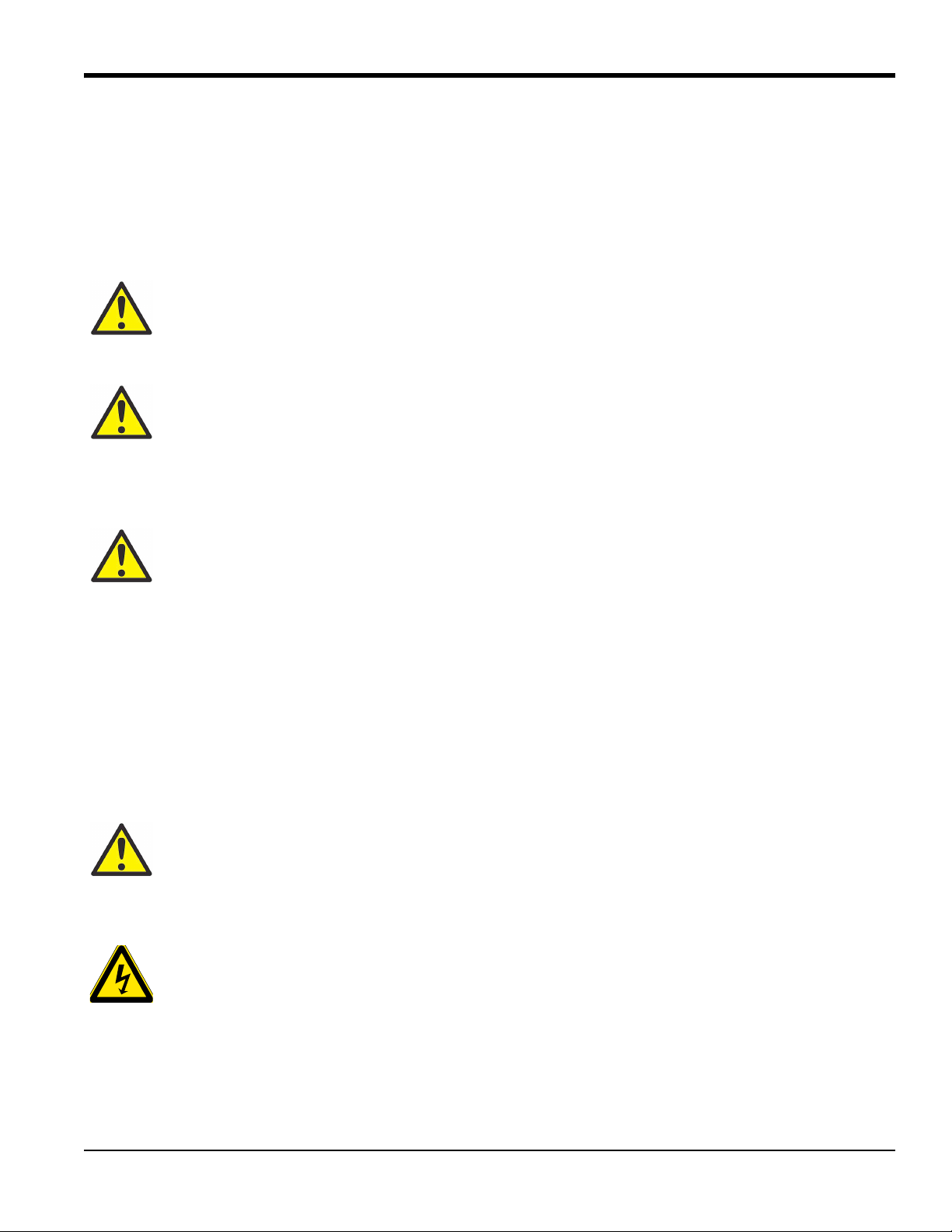
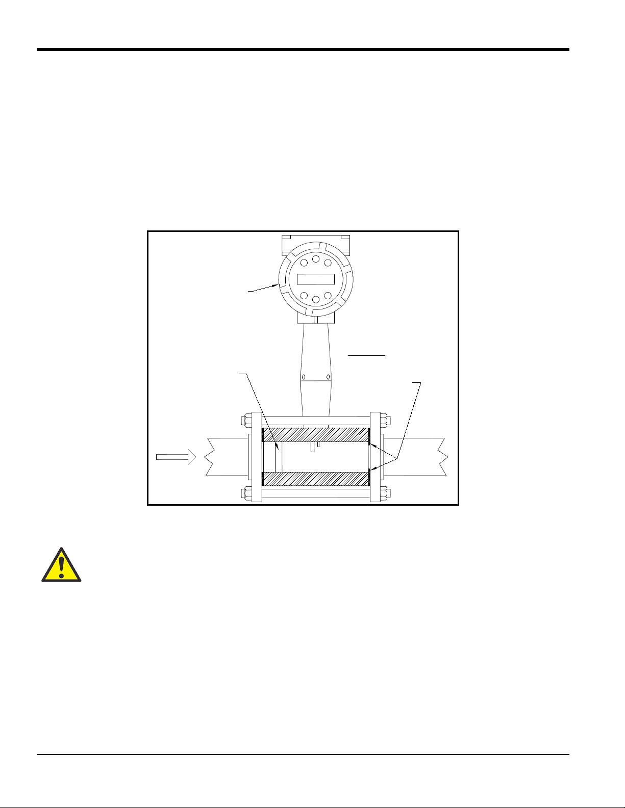
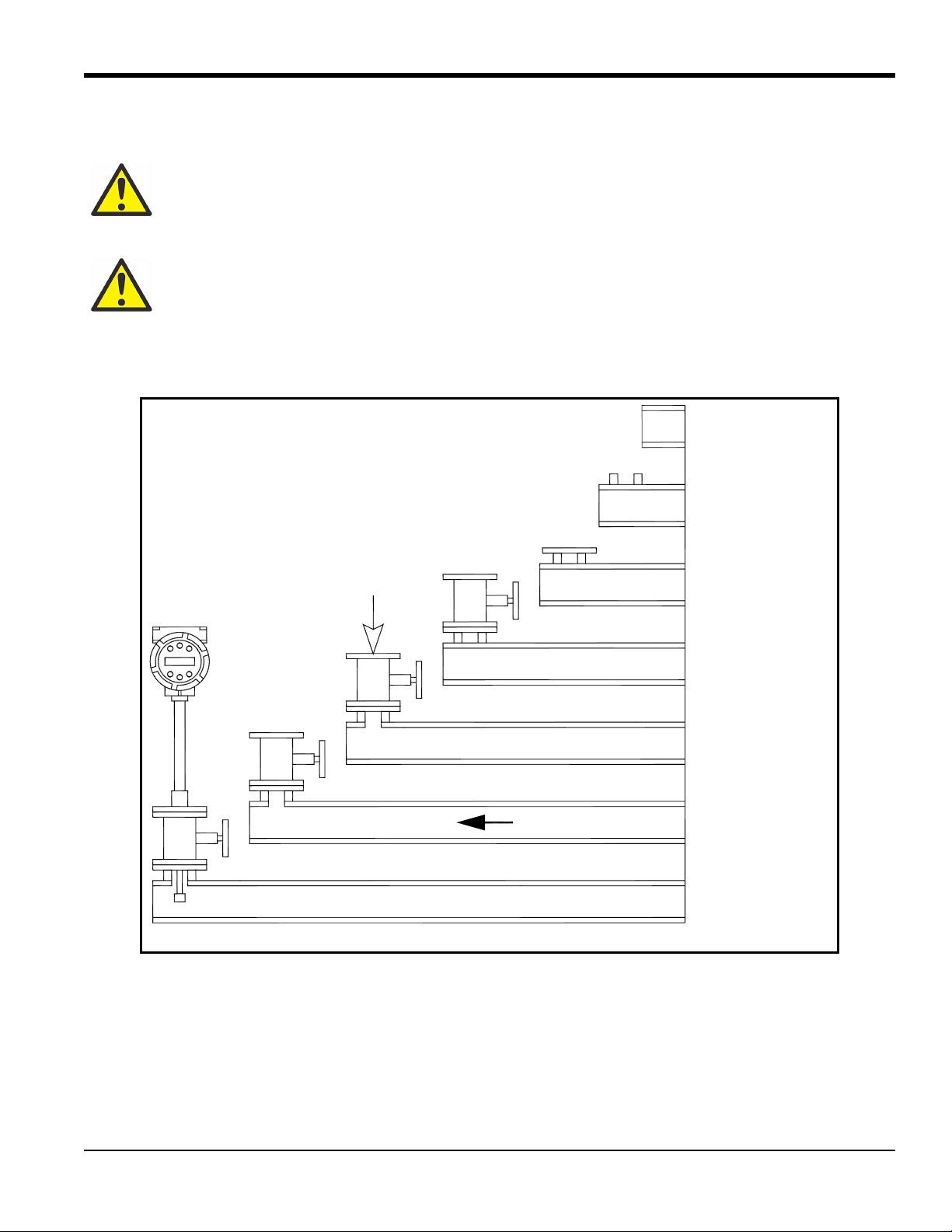
1.2 How the PanaFlow Vortex Mass Flowmeter Operates
PanaFlow MV80 and MV82 Mass Flowmeters (see Figure 1 below) use a unique sensor head to monitor mass flow
rate by directly measuring three variables-fluid velocity, temperature and pressure. The built-in flow computer
calculates the mass flow rate and volumetric flow rate based on these three direct measurements. The velocity,
temperature and pressure sensing head is built into the vortex meter's flow body. To measure fluid velocity, the
flowmeter incorporates a bluff body (shedder bar) in the flow stream and measures the frequency of vortices created by
the shedder bar. Temperature is measured using a platinum resistance temperature detector (PRTD). Pressure
measurement is achieved using a solid-state pressure transducer. All three elements are combined into an integrated
sensor head assembly located downstream of the shedder bar within the flow body.
Figure 1: In-Line Vortex Multi-Parameter Mass Flowmeter
1.3 Velocity Measurement
The PanaFlow vortex velocity sensor is a patented mechanical design that minimizes the effects of pipeline vibration
and pump noise, both of which are common error sources in flow measurement with vortex flowmeters. The velocity
measurement is based on the well-known Von Karman vortex shedding phenomenon. Vortices are shed from a shedder
bar, and the vortex velocity sensor located downstream of the shedder bar senses the passage of these vortices. This
method of velocity measurement has many advantages including inherent linearity, high turndown, reliability and
simplicity.
2 PanaFlow™ MV80 & MV82 User’s Manual
Page 15
Chapter 1. Introduction
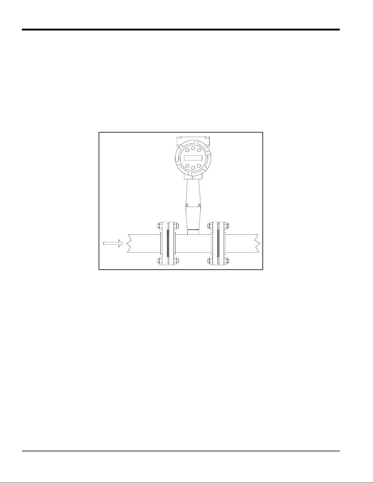
Vortex Shedder Bar
Velocity Sensor
Vortices
Constant Wave Length
Flow
1.3.1 Vortex Shedding Frequency
Von Karman vortices form downstream of a shedder bar into two distinct wakes. The vortices of one wake rotate
clockwise while those of the other wake rotate counterclockwise. Vortices generate one at a time, alternating from the
left side to the right side of the shedder bar. Vortices interact with their surrounding space by over-powering every other
nearby swirl on the verge of development. Close to the shedder bar, the distance (or wave length) between vortices is
always constant and measurable. Therefore, the volume encompassed by each vortex remains constant, as shown in
Figure 2 below. By sensing the number of vortices passing by the velocity sensor, the PanaFlow™ Flowmeter
computes the total fluid volume.
Figure 2: Measurement Principle of Vortex Flowmeters
1.3.2 Vortex Frequency Sensing
The velocity sensor incorporates a piezoelectric element that senses the vortex frequency. This element detects the
alternating lift forces produced by the Von Karman vortices flowing downstream of the vortex shedder bar. The
alternating electric charge generated by the piezoelectric element is processed by the transmitter's electronic circuit to
obtain the vortex shedding frequency. The piezoelectric element is highly sensitive and operates over a wide range of
flows, pressures and temperatures.
PanaFlow™ MV80 & MV82 User’s Manual 3
Page 16
Chapter 1. Introduction
25ft/s
ρ
---------------
37m/s
ρ
----------------
Re
ρVD
μ
----------
=
St
fd
V
-----=
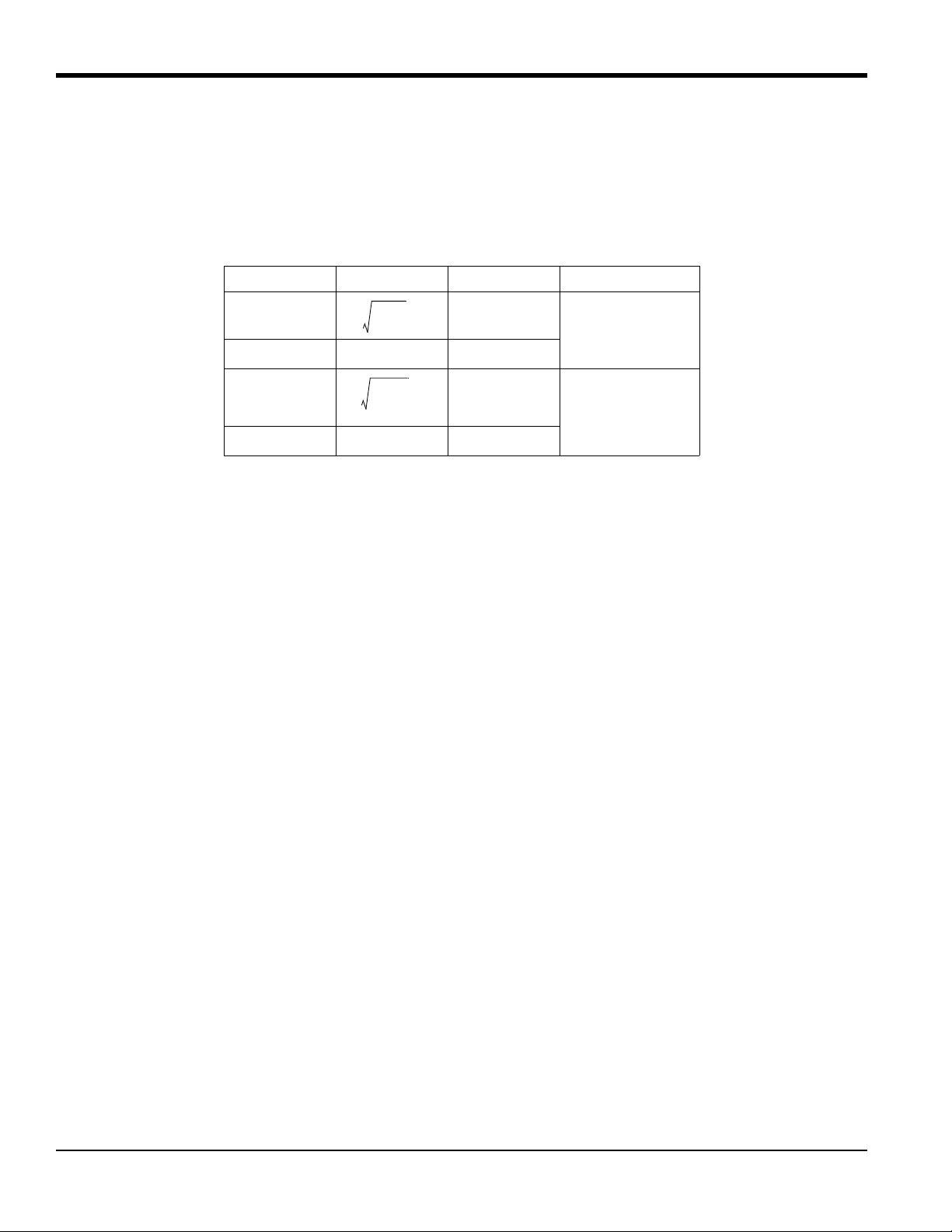
1.3.3 Flow Velocity Range
To ensure trouble-free operation, vortex flowmeters must be correctly sized so that the flow velocity range through the
meter lies within the measurable velocity range (with acceptable pressure drop) and the linear range.
The measurable range is defined by the minimum and maximum velocity using Table 1 below.
Table 1: Measurable Ranges
Parameter Gas Liquid Units for ρ
V
min
1 ft/s
English
ρ (lb/ft
3
)
V
max
V
min
V
max
300 ft/s 30 ft/s
0.3 m/s
91 m/s 9.1 m/s
Metric
ρ (kg/m
3
)
The pressure drop for series MV82 insertion meters is negligible. The pressure drop for series MV80 in-line meters is
defined as:
ΔP = .00024
ΔP = .000011
2
ρV
English units (ΔP in psi, ρ in lb/ft
2
ρV
Metric units (ΔP in bar, ρ in kg/m
3
, V in ft/sec)
3
, V in m/sec)
The linear range is defined by the Reynolds number. The Reynolds number is the ratio of the inertial forces to the
viscous forces in a flowing fluid and is defined as:
Where,
Re = Reynolds Number
ρ = mass density of the fluid being measured
V = velocity of the fluid being measured
D = internal diameter of the flow channel
μ = viscosity of the fluid being measured
The Strouhal number is the other dimensionless number that quantifies the vortex phenomenon. The Strouhal number
is defined as:
Where,
St = Strouhal Number
f = frequency of vortex shedding
d = shedder bar width
V = fluid velocity
4 PanaFlow™ MV80 & MV82 User’s Manual
Page 17
Chapter 1. Introduction
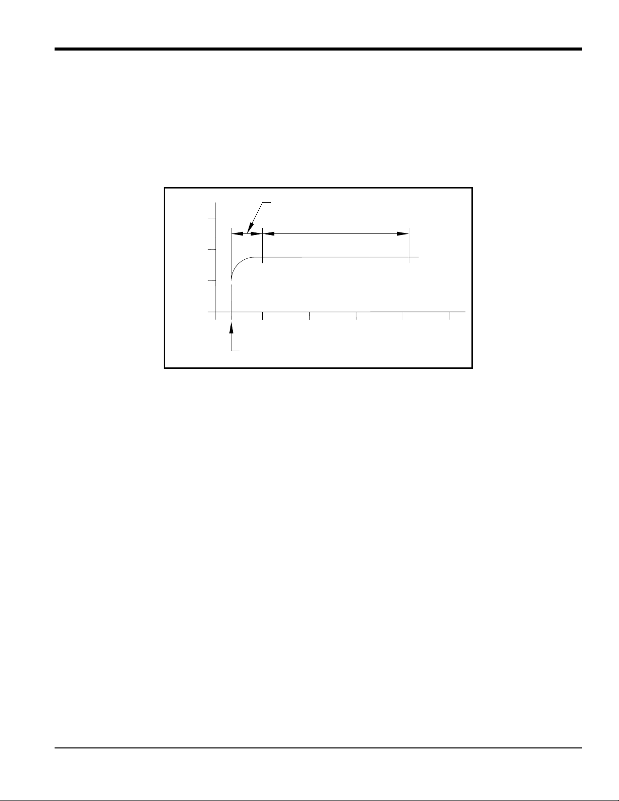
0.0
0.1
0.2
0.3
10
3
10
4
10
5
10
6
10
7
10
8
Linear Range
Reynolds Number, Re
1.3.3 Flow Velocity Range (cont.)
As shown in Figure 3 below, PanaFlow meters exhibit a constant Strouhal number across a large range of Reynolds
numbers, indicating a consistent linear output over a wide range of flows and fluid types. Below this linear range, the
intelligent electronics in PanaFlow automatically corrects for the variation in the Strouhal number with the Reynolds
number. The meter's smart electronics corrects for this non-linearity via its simultaneous measurements of the process
fluid temperature and pressure. This data is then used to calculate the Reynolds number in real time. PanaFlow meters
automatically correct down to a Reynolds number of 5,000.
Corrected Range
Strouhal Number, St
5000
Figure 3: Reynolds Number Range for the PanaFlow MV
1.4 Temperature Measurement
PanaFlow Flowmeters use a 1000 ohm platinum resistance temperature detector (PRTD) to measure fluid temperature.
1.5 Pressure Measurement
PanaFlow Flowmeters incorporate a solid-state pressure transducer isolated by a 316 stainless steel diaphragm. The
transducer itself is micro-machined silicon, fabricated using integrated circuit processing technology. A nine-point
pressure/temperature calibration is performed on every sensor. Digital compensation allows these transducers to
operate within a 0.3% of full scale accuracy band within the entire ambient temperature range of –40°F to 140°F
(–40 to 60°C). Thermal isolation of the pressure transducer ensures the same accuracy across the allowable process
fluid temperature range of –330°F to 750°F (–200 to 400°C).
PanaFlow™ MV80 & MV82 User’s Manual 5
Page 18

Chapter 1. Introduction
1.6 Flowmeter Configurations
PanaFlow Vortex Mass Flowmeters are available in two model configurations:
• Series MV80 in-line flowmeter (replaces a section of the pipeline)
• Series MV82 insertion flowmeter (requires a “cold” tap or a “hot” tap into an existing pipeline)
Both the in-line and insertion configurations are similar in that they both use identical electronics and have similar
sensor heads. Besides installation differences, the main difference between an in-line flowmeter and an insertion
flowmeter is their method of measurement.
For an in-line vortex flowmeter, the shedder bar is located across the entire diameter of the flow body. Thus, the entire
pipeline flow is included in the vortex formation and measurement. The sensing head, which directly measures
velocity, temperature and pressure is located just downstream of the shedder bar.
Insertion vortex flowmeters have a shedder bar located across the diameter of a short tube. The velocity, temperature
and pressure sensor are located within this tube just downstream of a built-in shedder bar. This entire assembly is called
the insertion sensing head. It fits through any entry port with a 1.875 inch minimum internal diameter.
The sensing head of an insertion vortex flowmeter directly monitors the velocity at a point in the cross-sectional area of
a pipe, duct, or stack (referred to as “channels”). The velocity at a point in the pipe varies as a function of the Reynolds
number. The insertion vortex flowmeter computes the Reynolds number and then computes the total flow rate in the
channel. The output signal of insertion meters is the total flow rate in the channel. The accuracy of the total flow rate
computation depends on adherence to the piping installation requirements given in Chapter 2. If adherence to those
guidelines cannot be met, contact GE for specific installation advice.
1.6.1 Multivariable Options
The MV80 or MV82 models are available with the following options:
• V = volumetric flowmeter
• VT = velocity and temperature sensors
• VTP = velocity, temperature, and pressure sensors
• VT-EM = energy output options
• VTP-EM = energy options with pressure
• VT-EP = external pressure transmitter input.
6 PanaFlow™ MV80 & MV82 User’s Manual
Page 19

Chapter 1. Introduction
1.6.2 Line Size, Process Connections and Materials
The MV80 In-line model is built for line sizes ½ through 4 inch wafer or ½ through 8 inch flanged design using
ANSI 150, 300, 600, PN16, 40, or 64 class flanges.
The MV82 Insertion model can be used in line sizes 2 inch and greater and is built with a compression fitting or
packing gland design using 2 inch NPT, or 2 inch flanged connections (ANSI 150, 300, 600, PN16, 40, or 64 class
flanges). The packing gland design can be ordered with a permanent or removable retractor.
The MV80 In-line model can be built with A105 carbon steel, 316L stainless steel, or Hastelloy C-276. The MV82
Insertion model can be built with 316L stainless steel or Hastelloy C-276.
1.6.3 Flowmeter Electronics
PanaFlow flowmeter electronics are available mounted directly to the flow body, or remotely mounted. The electronics
housing may be used indoors or outdoors, including wet environments. Available input power options are: DC loop
powered (2-wire), DC powered or AC powered. Three analog output signals are available for your choice of three of
the five process variables: mass flow rate, volumetric flow rate, temperature, pressure or fluid density. A pulse output
signal for remote totalization and MODBUS or HART communications are also available.
PanaFlow flowmeters include a local 2 x16 character LCD display housed within the enclosure. Local operation and
reconfiguration is accomplished using six push buttons operated via finger touch. For hazardous locations, the six
buttons can be operated with the electronics enclosure sealed using a hand-held magnet, thereby not compromising the
integrity of the hazardous location certification.
The electronics include nonvolatile memory that stores all configuration information. The nonvolatile memory allows
the flowmeter to function immediately upon power up, or after an interruption in power. All flowmeters are calibrated
and configured for the customer's flow application.
PanaFlow™ MV80 & MV82 User’s Manual 7
Page 20

Chapter 1. Introduction
[no content intended for this page]
8 PanaFlow™ MV80 & MV82 User’s Manual
Page 21

Chapter 2. Installation
Chapter 2. Installation
2.1 Installation Overview
PanaFlow Vortex Flowmeter installations are simple and straightforward. Both the Series MV80 In-Line and Series
MV82 Insertion type flowmeter installations are covered in this chapter. After reviewing the installation requirements
given below, see page 11 for Series MV80 installation instructions. See “Series MV82 Insertion Flowmeter
Installation” on page 15 for Series MV82 installation instructions. Wiring instructions begin in “Loop Power
Flowmeter Wiring Connections” on page 32.
2.1.1 Flowmeter Installation Requirements
WARNING! Consult the flowmeter nameplate for specific flowmeter approvals before any
hazardous location installation.
Before installing the flowmeter, verify that the installation site allows for these considerations:
1. Line pressure and temperature will not exceed the flowmeter rating.
2. The location meets the required minimum number of pipe diameters upstream and downstream of the sensor
head as illustrated in Figure 4 on page 10.
3. Safe and convenient access with adequate overhead clearance for maintenance purposes.
4. Verify that the cable entry into the instrument meets the specific standard required for hazardous area
installations.
5. For remote installations, verify the supplied cable length is sufficient to connect the flowmeter sensor to the
remote electronics.
Also, before installation, check your flow system for anomalies such as:
• Leaks
• Valves or restrictions in the flow path which could create disturbances in the flow profile that might cause
unexpected flow rate indications
PanaFlow™ MV80 & MV82 User’s Manual 9
Page 22
Chapter 2. Installation
Flowmeter
AB
Example 1.
One 90° elbow before meter
Flowmeter
AB
Example 2.
Two 90° elbows before meter in one plane
C' C
Flow Conditioner
(if used)
Flowmeter
AB
Example 3.
Two 90° elbows before meter out of plane (if three
C' C
Flow Conditioner
(if used)
90° bends present, double recommended length)
Flowmeter
AB
Example 4.
Reduction before meter
Flowmeter
AB
Example 5.
Expansion before meter
C' C
Flow Conditioner
(if used)
C' C
Flow Conditioner
(if used)
Flowmeter
AB
Example 6.
Regulator or valve partially closed before meter
C' C
Flow Conditioner
(if used)
(If valve is always wide open, base length
requirements on fitting directly preceding it)
Example
1
2
3
4
5
6
A
10D
15D
25D
10D
20D
25D
No Flow
Conditioner
A
N/A
10D
10D
10D
10D
10D
With Flow Conditioner
C
N/A
5D
5D
5D
5D
5D
C'
N/A
5D
5D
5D
5D
5D
No Flow
Conditioner
With Flow
Conditioner
Minimum Required
Downstream Diameters
Minimum Required
Upstream Diameters
D = Internal diameter of channel. N/A = Not applicable.
B
5D
5D
10D
5D
5D
10D
B
5D
5D
5D
5D
5D
5D
2.1.2 Unobstructed Flow Requirements
Select an installation site that will minimize possible distortion in the flow profile. Valves, elbows, control valves and
other piping components may cause flow disturbances. Check your specific piping condition against the examples
shown in Figure 4 below. In order to achieve accurate and repeatable performance install the flowmeter using the
recommended number of straight run pipe diameters upstream and downstream of the sensor.
Note: For liquid applications in vertical pipes, avoid installing with flow in the downward direction because the pipe
may not be full at all points. Choose to install the meter with flow in the upward direction if possible.
Figure 4: Recommended Pipe Length Requirements for Installation of Series MV80 & MV82
10 PanaFlow™ MV80 & MV82 User’s Manual
Page 23
Chapter 2. Installation
1
2
34
1
2
34
1
2
34
8
67
5
8
12 5
9
7
116
10
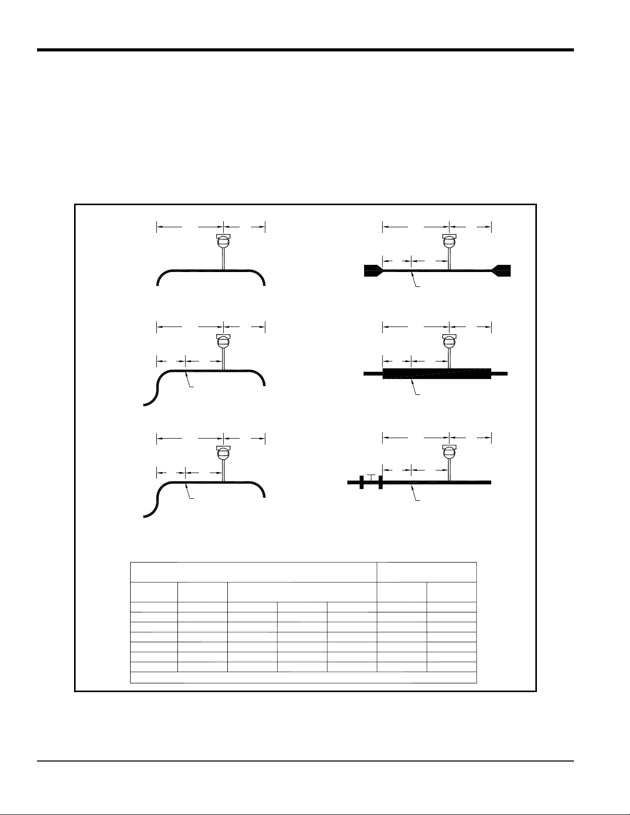
2.2 Series MV80 In-Line Flowmeter Installation
Install the Series MV80 In-Line Flowmeter between two conventional pipe flanges as shown in Figure 6 on page 12
and Figure 7 on page 14. Table 2 below provides the recommended minimum stud bolt lengths for wafer-style meter
body size and different flange ratings.
The meter inside diameter is equal to the same size nominal pipe ID in schedule 80. For example, a 2" meter has an ID
of 1.939" (2" schedule 80). Do not install the meter in a pipe with an inside diameter smaller than the inside diameter of
the meter. For schedule 160 and higher pipe, a special meter is required. Consult GE before purchasing the meter.
Series MV80 Meters require customer-supplied gaskets. When selecting gasket material make sure that it is compatible
with the process fluid and pressure ratings of the specific installation. Verify that the inside diameter of the gasket is
larger than the inside diameter of the flowmeter and adjacent piping. If the gasket material extends into the flow stream,
it will disturb the flow and cause inaccurate measurements.
2.2.1 Flange Bolt Specifications
Table 2: Minimum Recommended Stud Bolt Lengths for Wafer Meters
Stud Bolt Lengths for Each Flange Rating (inches)
Line Size Class 150 and PN16 Class 300 and PN40 Class 600 and PN64
1 inch 6.00 7.00 7.50
1.5 inch 6.25 8.50 9.00
2 inch 8.50 8.75 9.50
3 inch 9.00 10.00 10.50
4 inch 9.50 10.75 12.25
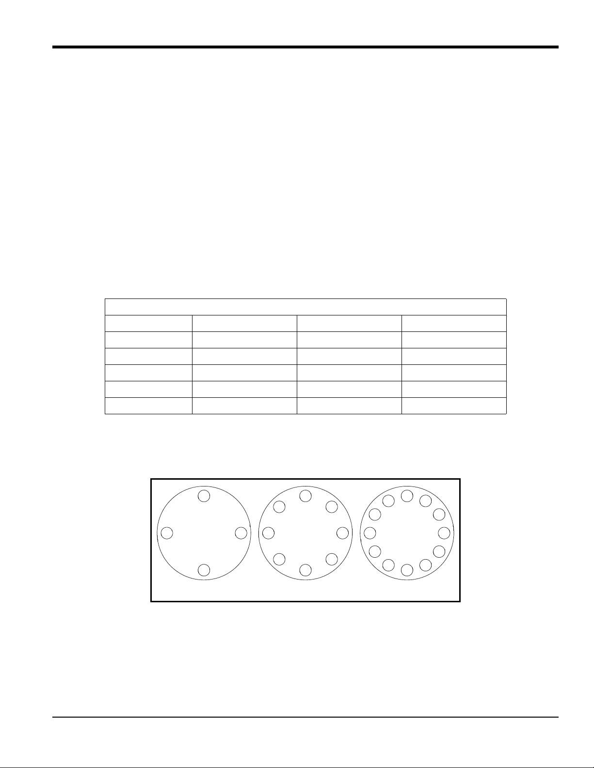
The required bolt load for sealing the gasket joint is affected by several application-dependent factors. Therefore the
required torque for each application may be different. Refer to the ASME Pressure Vessel Code guidelines for bolt
tightening standards and refer to Figure 5 below for the proper bolt tightening sequence.
4-bolt 8-bolt 12-bolt
Figure 5: Flange Bolt Torquing Sequence
PanaFlow™ MV80 & MV82 User’s Manual 11
Page 24
Chapter 2. Installation
F
LOW
Enclosure and
display/keypad
are adjustable to suit
most viewing angles.
Incorrect gasket position!
Do not allow any gasket
material to extend into
the flow profile.
Shedder bar (bluff body)
is positioned upstream
of the sensor.
2.2.2 Installing Wafer-Style Flowmeters
Install the wafer-style meter between two conventional pipe flanges of the same nominal size as the flowmeter (see
Figure 6 below). If the process fluid is a liquid, make sure the meter is located where the pipe is always full. This may
require locating the meter at a low point in the piping system.
Note: Vortex flowmeters are not suitable for two-phase flows, such as liquid and gas mixtures.
For horizontal pipelines having a process temperature above 300° F, mount the meter at a 45 or 90-degree angle to
avoid overheating the electronics enclosure. To adjust the viewing angle of the enclosure or display/keypad, see
“Display/Keypad Adjustment (All Meters)” on page 30 and “Enclosure Adjustment (Series MV80 Only)” on page 31.
When installing the meter make sure the section marked with a flow arrow is positioned upstream of the outlet, with the
arrow head pointing in the direction of flow. (The mark is on the wafer adjacent to the enclosure mounting neck.) This
ensures that the sensor head is positioned downstream of the vortex shedder bar and is correctly aligned to the flow.
Installing the meter opposite this direction will result in completely inaccurate flow measurement.
12 PanaFlow™ MV80 & MV82 User’s Manual
Figure 6: Wafer-Style Flowmeter Installation
CAUTION! When using toxic or corrosive gases, purge the line with inert gas for a minimum of four
hours at full gas flow before installing the flowmeter.
Page 25

Chapter 2. Installation
2.2.2 Installing Wafer-Style Flowmeters (cont.)
To install the meter, complete the following steps:
1. Turn off the flow of process gas, liquid or steam. Verify that the line is not pressurized. Confirm that the
installation site meets the required minimum upstream and downstream pipe diameters.
2. Insert the studs for the bottom side of the meter body between the pipe flanges. Place the wafer-style meter
body between the flanges with the end stamped with a flow arrow on the upstream side, with the arrow head
pointing in the direction of flow. Center the meter body inside the diameter with respect to the inside diameter
of the adjoining piping.
3. Position the gasket material between the mating surfaces. Make sure both gaskets are smooth and even with no
gasket material extending into the flow profile. Obstructions in the pipeline will disturb the flow and cause
inaccurate measurements.
4. Place the remaining studs between the pipe flanges. Tighten the nuts in the sequence shown in Figure 5 on
page 11. Check for leaks after tightening the flange bolts.
PanaFlow™ MV80 & MV82 User’s Manual 13
Page 26
Chapter 2. Installation
LOW
Enclosure and
display/keypad
are adjustable to suit
most viewing angles.
Incorrect gasket position!
Do not allow any gasket
material to extend into
the flow profile.
Shedder bar (bluff body)
is positioned upstream
of the sensor.
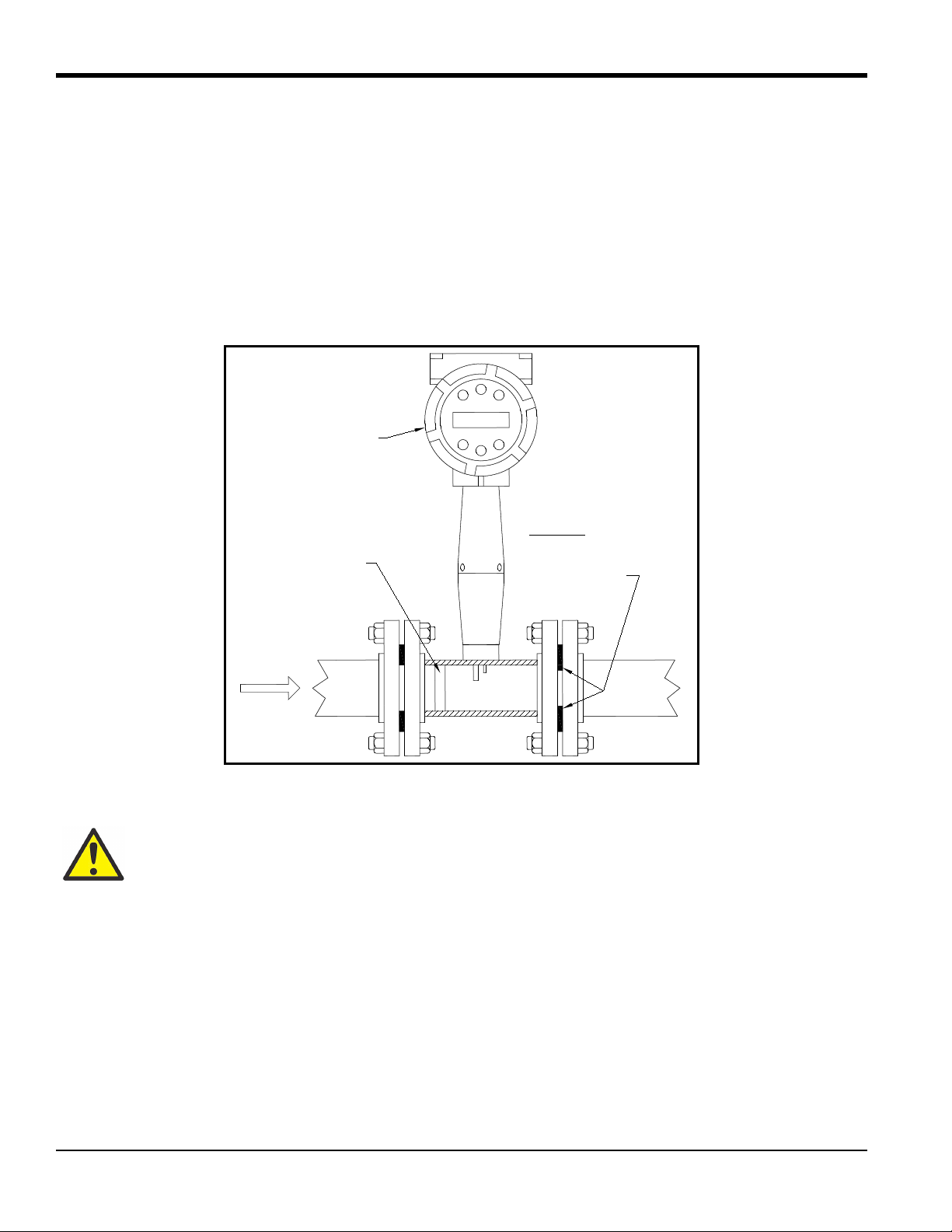
2.2.3 Installing Flange-Style Flowmeters
Install the flange-style meter between two conventional pipe flanges of the same nominal size as the flowmeter (see
Figure 7 below). If the process fluid is a liquid, make sure the meter is located where the pipe is always full. This may
require locating the meter at a low point in the piping system.
Note: Vortex flowmeters are not suitable for two-phase flows, such as liquid and gas mixtures.
For horizontal pipelines having a process temperature above 300° F, mount the meter at a 45 or 90-degree angle to
avoid overheating the electronics enclosure. To adjust the viewing angle of the enclosure or display/keypad, see
“Display/Keypad Adjustment (All Meters)” on page 30 and “Enclosure Adjustment (Series MV80 Only)” on page 31.
F
Figure 7: Flange-Style Flowmeter Installation
CAUTION! When using toxic or corrosive gases, purge the line with inert gas for a minimum of four
hours at full gas flow before installing the flowmeter.
When installing the meter make sure the flange marked with a flow arrow is positioned upstream of the outlet flange,
with the arrow head pointing in the direction of flow. The mark is on the flange adjacent to the enclosure mounting
neck. This ensures that the sensor head is positioned downstream of the vortex shedder bar and is correctly aligned to
the flow. Installing the meter opposite this direction will result in completely inaccurate flow measurement.
14 PanaFlow™ MV80 & MV82 User’s Manual
Page 27
Chapter 2. Installation
valve bore
2-inch min.
2-inch
valve size
2.2.3 Installing Flange-Style Flowmeters (cont.)
To install the meter, complete the following steps:
1. Turn off the flow of process gas, liquid or steam. Verify that the line is not pressurized. Confirm that the
installation site meets the required minimum upstream and downstream pipe diameters.
2. Seat the meter level and square on the mating connections with the flange stamped with a flow arrow on the
upstream side, with the arrow head pointing in the direction of flow. Position a gasket in place for each side.
Make sure both gaskets are smooth and even with no gasket material extending into the flow profile.
Obstructions in the pipeline will disturb the flow and cause inaccurate measurements.
3. Install bolts in both process connections. Tighten the nuts in the sequence shown in Figure 5 on page 11. Check
for leaks after tightening the flange bolts.
2.3 Series MV82 Insertion Flowmeter Installation
2.3.1 General Installation Guidelines
Prepare the pipeline for installation using either a cold tap or hot tap method described in this section. Refer to a
standard code for all pipe tapping operations. The following tapping instructions are general in nature and intended for
guideline purposes only. Before installing the meter, review the mounting position and isolation value requirements
given in the following sub-sections.
2.3.1a Electronics Enclosure Clearance
Allow clearance between the electronics enclosure top and any obstruction when the meter is fully retracted.
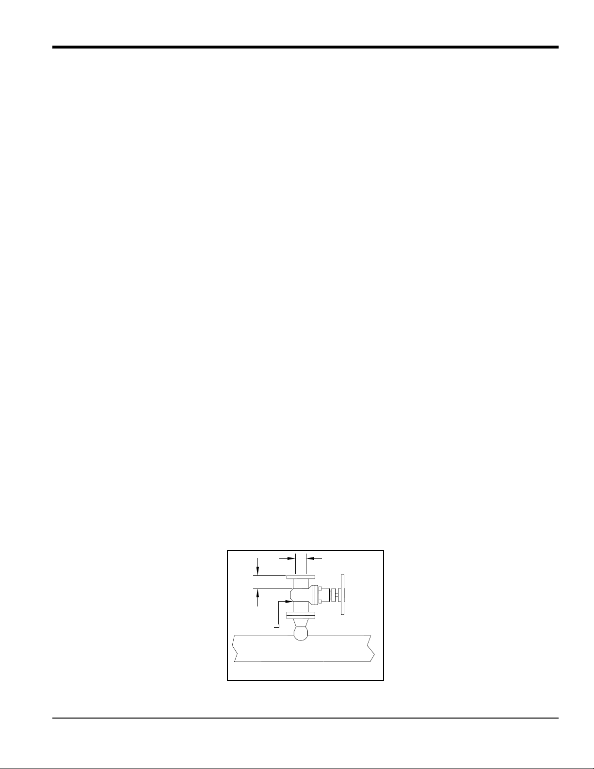
2.3.1b Isolation Valve Selection
An isolation valve is available as an option with Series MV82 meters. If you supply the isolation valve, refer to
Figure 8 below and verify that it meets the following requirements:
1. A minimum valve bore diameter of 1.875 inches is required, and the valve’s body size should be two inches.
Normally, gate valves are used.
2. Verify that the valve’s body and flange rating are within the flowmeter’s maximum operating pressure and
temperature.
3. Choose an isolation valve with at least a two inch distance between the flange face and the gate portion of the
valve. This ensures that the flowmeter’s sensor head will not interfere with the operation of the isolation valve.
1.875-inch min.
Isolation Valve Requirements
Figure 8: Isolation Valve Dimensions
PanaFlow™ MV80 & MV82 User’s Manual 15
Page 28
Chapter 2. Installation
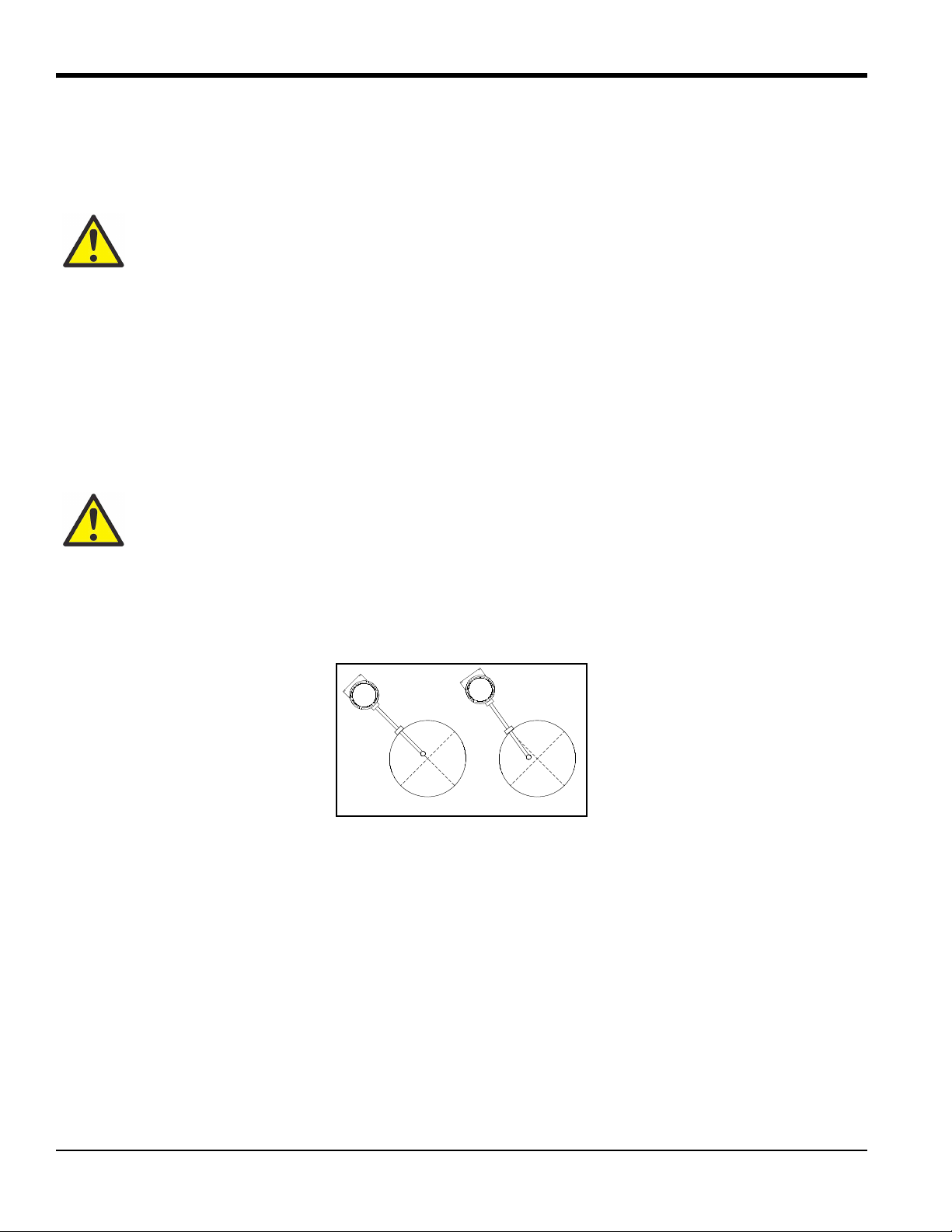
Incorrect AlignmentCorrect Alignment
2.3.1c Cold Tap Guidelines
Refer to a standard code for all pipe tapping operations. The following tapping instructions are general in nature and
intended for guideline purposes only. Proceed as follows:
CAUTION! When using toxic or corrosive gases, purge the line with inert gas for a minimum of four
hours at full gas flow before installing the flowmeter.
1. Turn off the flow of process gas, liquid or steam. Verify that the line is not pressurized.
2. Confirm that the installation site meets the minimum upstream and downstream pipe diameter requirements.
See Figure 4 on page 10.
3. Use a cutting torch or sharp cutting tool to tap into the pipe. The pipe opening must be at least 1.875 inches in
diameter. (Do not attempt to insert the sensor probe through a smaller hole.)
4. Remove all burrs from the tap. Rough edges may cause flow profile distortions that could affect flowmeter
accuracy. Also, obstructions could damage the sensor assembly when inserting into the pipe.
WARNING! All flowmeter connections, isolation valves and fittings for cold tapping must have the
same or higher pressure rating as the main pipeline.
5. After cutting, measure the thickness of the cut-out and record this number for calculating the insertion depth.
6. Weld the flowmeter pipe connection on the pipe. Make sure this connection is within ± 5° perpendicular to the
pipe centerline (see Figure 9 below).
Figure 9: Connection Alignment
7. Install the isolation valve (if used).
8. When welding is complete and all fittings are installed, close the isolation valve or cap the line. Run a static
pressure check on the welds. If pressure loss or leaks are detected, repair the joint and retest.
9. Connect the meter to the pipe process connection.
10. Calculate the sensor probe insertion depth and insert the sensor probe into the pipe as described on the
following pages.
16 PanaFlow™ MV80 & MV82 User’s Manual
Page 29
Chapter 2. Installation
FLOW
Check upstream and
downstream piping
requirements.
Weld mounting
adapter.
Connect process
connection
(flange or NPT)
Connect
isolation valve.
Hot tap pipe
Test for leaks,
purge pipe.
Connect meter to
valve, calculate
insertion depth,
install flowmeter.
2.3.1d Hot Tap Guidelines
WARNING! Hot tapping must be performed by a trained professional. US. regulations often require
a hot tap permit. The manufacturer of the hot tap equipment and/or the contractor performing the
hot tap is responsible for providing proof of such a permit.
WARNING! All flowmeter connections, isolation valves, and fittings for hot tapping must have the
same pressure rating as the main pipeline or higher.
Refer to a standard code for all pipe tapping operations. The following tapping instructions and Figure 10 below are
general in nature and are intended for guideline purposes only.
Figure 10: Hot Tap Sequence
PanaFlow™ MV80 & MV82 User’s Manual 17
Page 30

Chapter 2. Installation
2.3.1d Hot Tap Guidelines (cont.)
Proceed as follows:
1. Confirm that the installation site meets the minimum upstream and downstream pipe diameter requirements.
2. Weld a two inch mounting adapter on the pipe. Make sure the mounting adapter is within ± 5° perpendicular to
the pipe centerline (see Figure 9 on page 16). The pipe opening must be at least 1.875 inches in diameter.
3. Connect a two inch process connection on the mounting adapter.
4. Connect an isolation valve on the process connection. The valve's full open bore must be at least 1.875 inches
in diameter.
5. Run a static pressure check on the welds. If pressure loss or leaks are detected, repair the joint and re-test.
6. Connect the hot tapping equipment to the isolation valve, open the isolation valve and drill at least a 1.875 inch
diameter hole.
7. Retract the drill, close the isolation valve, and remove the hot tapping equipment.
8. Connect the flowmeter to the isolation valve and open the isolation valve.
9. Calculate the sensor probe insertion depth and insert the sensor probe into the pipe as described on the
following pages.
18 PanaFlow™ MV80 & MV82 User’s Manual
Page 31

Chapter 2. Installation
2.3.1e Insertion Guidelines
The sensor head must be properly positioned in the pipe. For this reason, it is important that insertion length
calculations are carefully followed. A sensor probe inserted at the wrong depth in the pipe will result in inaccurate
readings.
Insertion flowmeters are applicable to pipes 2 inch and larger. For pipe sizes ten inches and smaller, the centerline of
the meter's sensing head is located at the pipe's centerline. For pipe sizes larger than ten inches, the centerline of the
sensing head is located in the pipe's cross section five inches from the inner wall of the pipe. That is, its “wetted” depth
from the wall to the centerline of the sensing head is five inches.
Insertion flowmeters are available in three probe lengths:
• Standard Probe configuration is used with most flowmeter process connections. The length (S) of the stem is
29.47 inches.
• Compact Probe configuration is used with compression fitting process connections. The length (S) of the stem
is 13.1 inches.
• 12-Inch Extended Probe configuration is used with exceptionally lengthy flowmeter process connections. The
length (
S) of the stem is 41.47 inches.
2.3.1f Selecting the Correct Insertion Formula
WARNING! An insertion tool must be used for any installation where a flowmeter is inserted under
pressure greater than 50 psig.
Depending on your flowmeter's process connection, use the applicable insertion length formula and installation
procedure as follows:
• For flowmeters with a compression type connection (NPT or flanged), follow the instructions beginning in
“Installing Flowmeters with a Compression Connection” on page 20.
• For flowmeters with a packing gland type connection (NPT or flanged), configured with an insertion tool,
follow the instructions in “Installing Flowmeters with a Packing Gland Connection” on page 23.
• For flowmeters with a packing gland type connection (NPT or flanged), configured without an insertion tool,
follow the instructions in “Installing Flowmeters with a Packing Gland Connection (No Insertion Tool)” on
page 28.
PanaFlow™ MV80 & MV82 User’s Manual 19
Page 32

Chapter 2. Installation
I
F
t
R
S
I
F
t
R
S
Flow
Flow
Insertion Length Formula
I = S – F – R – t
Where:
I = Insertion Length.
= Stem length - the distance from the center of the sensor head to the base of the enclosure adapter
(S = 29.47" for standard probes; S = 13.1" for compact; S = 41.47" for 12-inch extended).
F = Distance from the raised face of the flange or top of NPT stem housing to the outside of the pipe wall.
R = Pipe inside diameter + 2 for pipes ten inches and smaller.
R = Five inches for pipe diameters larger than ten inches
t = Thickness of the pipe wall. (Measure the disk cut-out from the tapping procedure or check a piping
2.3.2 Installing Flowmeters with a Compression Connection
Refer to Figure 11 below, and use the formula shown to determine insertion length for flowmeters (NPT and flanged)
with a compression process connection.
S
handbook for thickness.)
Figure 11: Insertion Calculation (Compression Type)
20 PanaFlow™ MV80 & MV82 User’s Manual
Page 33

Chapter 2. Installation
Compression Nut
Stem Housing
2-inch NPT
Connection
Compression Nut
Sensor Head
Flange
Connection
Sensor Alignment
Pointer
Encloser Adapter
Stem
Stem Housing
2.3.2 Installing Flowmeters with a Compression Connection (cont.)
Example:
To install a Series MV82 meter with a standard probe (S = 29.47 inches) into a 14 inch schedule 40 pipe, the following
measurements (in inches) are taken:
• F = 3 inches
• R = 5 inches
• t = 0.438 inches
Then, using the formula given in Figure 11 on page 20, the insertion length for this example is 21.03 inches. Insert the
stem through the fitting until an insertion length of 21.03 inches is measured with a ruler.
PanaFlow™ MV80 & MV82 User’s Manual 21
Figure 12: Flowmeter with a Compression Type Fitting
Page 34

Chapter 2. Installation
2.3.2 Installing Flowmeters with a Compression Connection (cont.)
CAUTION! The sensor alignment pointer must point downstream, in the direction of flow.
WARNING! To avoid serious injury, DO NOT loosen the compression fitting under pressure.
Refer to Figure 12 on page 21 and complete the following steps:
1. Refer to Figure 11 on page 20 and calculate the required sensor probe insertion length for your system.
2. Fully retract the stem until the sensor head is touching the bottom of the stem housing. Slightly tighten the
compression nut to prevent slippage.
3. Bolt or screw the flowmeter assembly into the process connection. Use PTFE tape or pipe sealant to improve
the seal and prevent seizing on NPT styles.
4. Hold the meter securely while loosening the compression fitting. Insert the sensor into the pipe until the
calculated insertion length (
housing, or to the raised face of the flanged version. Do not force the stem into the pipe.
I) is measured between the base of the enclosure adapter and the top of the stem
5. Align the sensor head using the sensor alignment pointer. Adjust the alignment pointer parallel to the pipe and
pointing downstream.
6. Tighten the compression fitting to lock the stem in position.
IMPORTANT: After the compression fitting is tightened, the position is permanent.
22 PanaFlow™ MV80 & MV82 User’s Manual
Page 35

Chapter 2. Installation
t
R
low
Insertion Length Formula
I = F + R + t –1.35
Where:
I = Insertion length.
F = Distance from the raised face of the flange or top of the process
connection for NPT style meters to the top outside of the process pipe.
R = Pipe inside diameter ÷ 2 for pipe diameters 10 inches and smaller.
R = Five inches for pipe diameters larger than 10 inches.
t = Thickness of the pipe wall. (Measure the disk cut-
out from the tapping
procedure or check a piping handbook for thickness.)
I
F
2.3.3 Installing Flowmeters with a Packing Gland Connection
Use the formula in Figure 13 below to determine the insertion depth for flowmeters (NPT and flanged) equipped with
an insertion tool. To install, see “Insertion Procedure for Flowmeters with Permanent Insertion Tool” on page 24 for
instructions for meters with a permanent insertion tool. For meters with a removable insertion tool, see “Insertion
Procedure for Flowmeters with Removable Insertion Tool” on page 26.
F
Figure 13: Insertion Length Calculation for Meters with an Insertion Tool
Example 1 - Flange Style Meters:
To install a Series MV82 Flowmeter into a 14 inch schedule 40 pipe, the following measurements are taken:
• F = 12 inches
• R = 5 inches
• t = 0.438 inches
Then, using the formula given in Figure 13 above, the insertion length for this example is 16.09 inches.
PanaFlow™ MV80 & MV82 User’s Manual 23
Page 36

Chapter 2. Installation
Flow
Sensor Head
Stem Housing
Packing Gland Nuts
Stem
Sensor Alignment
Pointer
Stem Lock Bolt
(center)
Upper Retractor Bracket
Depth Marker Arrow
Stanchion
Scribe Mark
Permanent
Insertion Tool
2.3.3 Installing Flowmeters with a Packing Gland Connection (cont.)
Example 2 - NPT Style Meters:
In this example, the length of thread engagement on the NPT style meters must also subtracted in the equation shown in
Figure 13 on page 23. The length of the threaded portion of the NPT meter is 1.18 inches. Measure the threaded
portion still visible after the installation and subtract that amount from 1.18 inches. This gives you the thread
engagement length. If this cannot be measured, use 0.55 inch for this amount.
• F = 12 inches
• R = 5 inches
• t = 0.438 inches
• thread engagement = 1.18 inches - visible thread length (or 0.55 inches nominal value)
For this example, the equation yields an insertion length of 15.54 inches.
2.3.4 Insertion Procedure for Flowmeters with Permanent Insertion Tool
Refer to Figure 14 below, and follow the instructions on the next page.
24 PanaFlow™ MV80 & MV82 User’s Manual
Figure 14: Flowmeter with Permanent Insertion Tool
Page 37

Chapter 2. Installation
2.3.4 Insertion Procedure for Flowmeters with Permanent Insertion Tool (cont.)
CAUTION! The sensor alignment pointer must point downstream, in the direction of flow.
Note: If line pressure is above 500 psig, it could require up to 25 ft-lb of torque to insert the flowmeter. Do not
confuse this with possible interference in the pipe.
1. Calculate the required sensor probe insertion length (see
Example 1 on page 23). Measure from the depth
marker arrow down the stanchion and scribe a mark at the calculated insertion depth.
2. Fully retract the flowmeter until the sensor head is touching the bottom of the stem housing. Attach the meter
assembly to the two inch full-port isolation valve, if used. Use PTFE tape or pipe sealant to improve the seal
and prevent seizing on NPT style meters.
3. Loosen the two packing gland nuts on the stem housing of the meter. Loosen the stem lock bolt adjacent to the
sensor alignment pointer. Align the sensor head using the sensor alignment pointer. Adjust the alignment
pointer parallel to the pipe and pointing downstream. Tighten the stem lock bolt to secure the sensor position.
4. Slowly open the isolation valve to the full open position. If necessary, slightly tighten the two packing gland
nuts to reduce the leakage around the stem.
5. Turn the insertion tool handle clockwise to insert the sensor head into the pipe. Continue until the top of the
upper retractor bracket aligns with the insertion length position scribed on the stanchion. Do not force the stem
into the pipe.
6. Tighten the packing gland nuts to stop leakage around the stem. Do not use a torque over 20 ft-lb.
PanaFlow™ MV80 & MV82 User’s Manual 25
Page 38

Chapter 2. Installation
Flow
Sensor Head
Stem Housing
Stem Clamp Bolts
Stem
Sensor Alignment
Pointer
Stem Lock Bolt
(center)
Upper Retractor Bracket
Depth Marker Arrow
Stanchion
Scribe Mark
Removable
Insertion Tool
Lower Retractor Bracket
Packing Gland Nuts
(covered by stem clamp)
Stem Clamp Nuts
2.3.5 Insertion Procedure for Flowmeters with Removable Insertion Tool
Refer to Figure 15 below, and follow the instructions on the next page.
Figure 15: Flowmeter with Removable Insertion Tool
26 PanaFlow™ MV80 & MV82 User’s Manual
Page 39

Chapter 2. Installation
2.3.5 Insertion Procedure for Flowmeters with Removable Insertion Tool (cont.)
CAUTION! The sensor alignment pointer must point downstream, in the direction of flow.
Note: If line pressure is above 500 psig, it could require up to 25 ft-lb of torque to insert the flowmeter. Do not
confuse this with possible interference in the pipe.
1. Calculate the required sensor probe insertion length. Measure from the depth marker arrow down the stanchion
and scribe a mark at the calculated insertion depth.
2. Fully retract the flowmeter until the sensor head is touching the bottom of the stem housing. Attach the meter
assembly to the two inch full-port isolation valve, if used. Use PTFE tape or pipe sealant to improve the seal
and prevent seizing on NPT style meters.
3. Remove the two top stem clamp nuts and loosen two stem clamp bolts. Slide the stem clamp away to expose
the packing gland nuts.
4. Loosen the two packing gland nuts. Loosen the stem lock bolt adjacent to the sensor alignment pointer. Align
the sensor head using the sensor alignment pointer. Adjust the alignment pointer parallel to the pipe and
pointing downstream. Tighten the stem lock bolt to secure the sensor position.
5. Slowly open the isolation valve to the full open position. If necessary, slightly tighten the two packing gland
nuts to reduce the leakage around the stem.
6. Turn the insertion tool handle clockwise to insert the stem into the pipe. Continue until the top of the upper
retractor bracket lines up with the insertion length mark scribed on the stanchion. Do not force the stem into the
pipe.
7. Tighten the packing gland nuts to stop leakage around the stem. Do not use a torque over 20 ft-lb.
8. Slide the stem clamp back into position, and torque stem clamp bolts to 15 ft-lb. Replace the stem clamp nuts
and torque them to 10-15 ft-lb.
9. To separate the insertion tool from the flowmeter, remove the four socket head cap bolts securing the upper and
lower retractor brackets. Then, remove the insertion tool.
PanaFlow™ MV80 & MV82 User’s Manual 27
Page 40

Chapter 2. Installation
t
R
F
low
Insertion Length Formula
I = S – F – R – t
Where:
I = Insertion length.
S = Stem length - the distance from the center of the sensor head
to the base of the enclosure adapter (S = 41.47 inches for
12 inch extended probes).
F = Distance from the raised face of the flange or top of NPT stem
housing to the outside of the pipe wall.
R = Pipe inside diameter ÷ 2 for pipes ten inches and sma
ller.
R = Five inches for pipe diameters larger than ten inches.
t = Thickness of the pipe wall. (Measure the disk cut-out from the
tapping procedure or check a piping handbook for thickness.)
I
F
S
2.3.6 Installing Flowmeters with a Packing Gland Connection (No Insertion Tool)
Use the formula in Figure 16 below to determine the insertion depth for meters with a packing gland connection (NPT
and flanged) without an insertion tool.
Figure 16: Insertion Calculation for Meters Without an Insertion Tool)
Example:
To install a Series MV82 Flowmeter with a standard probe (S = 29.47) into a 14 inch schedule 40 pipe, the following
measurements are taken:
• F = 3 inches
• R = 5 inches
• t = 0.438 inches
For this example, the calculated insertion length is 21.03 inches.
28 PanaFlow™ MV80 & MV82 User’s Manual
Page 41

Chapter 2. Installation
2.3.6 Installing Flowmeters with a Packing Gland Connection (No Insertion Tool) (cont.)
WARNING! The line pressure must be less than 50 psig for installation.
To install the meter, complete the following steps:
1. Calculate the required sensor probe insertion length.
2. Fully retract the stem until the sensor head is touching the bottom of the stem housing. Remove the two top
stem clamp nuts and loosen two stem clamp bolts. Slide the stem clamp away to expose the packing gland nuts.
Loosen the two packing gland nuts.
CAUTION! The sensor alignment pointer must point downstream, in the direction of flow.
3. Align the sensor head using the sensor alignment pointer. Adjust the alignment pointer parallel to the pipe and
pointing downstream.
4. Insert the sensor head into the pipe until the correct insertion length (
I) is achieved. Do not force the stem into
the pipe.
5. Tighten the packing gland nuts to stop leakage around the stem. Do not use a torque over 20 ft-lb.
6. Slide the stem clamp back into position, and torque the stem clamp bolts to 15 ft-lb. Replace the stem clamp
nuts and torque them to 10-15 ft-lb.
2.4 Adjusting the Meter Orientation
Depending on installation requirements, you may need to adjust the meter orientation. There are two adjustments
available. The first rotates the position of the LCD display/keypad and is available on both in-line and insertion meters.
The second rotates the enclosure position. This adjustment is allowed only on Series MV80 in-line meters. Proceed to
the next page for instructions
PanaFlow™ MV80 & MV82 User’s Manual 29
Page 42

Chapter 2. Installation
Rotate display/keypad in 90° increments
(maximum 180° from original position).
2.4.1 Display/Keypad Adjustment (All Meters)
To adjust the display/keypad position, refer to Figure 17 below and complete the following steps:
Figure 17: Display/Keypad Viewing Adjustment
CAUTION! The electronics boards are electrostatically sensitive. Wear a grounding wrist strap and
make sure to observe proper handling precautions required for static-sensitive components.
1. Disconnect the power from the flowmeter.
2. Loosen the small set screw which secures the electronics enclosure cover. Unscrew and remove the cover.
3. Loosen the 4 captive screws.
4. Carefully pull the display/microprocessor circuit board away from the meter standoffs. Make sure not to
damage the connected ribbon cable.
5. Rotate the display/microprocessor circuit board to the desired position. The maximum allowable rotation is
two positions left or two positions right (180°).
6. Align the circuit board with the captive screws, and check that the ribbon cable is folded neatly behind the
board with no twists or crimps.
7. Tighten the screws. Replace the cover and set screw, and restore power to the meter.
30 PanaFlow™ MV80 & MV82 User’s Manual
Page 43

2.4.2 Enclosure Adjustment (Series MV80 Only)
Loosen three setscrews
and rotate enclosure
(maximum 180° from
original position)
To adjust the enclosure position, refer to Figure 18 below and complete the following steps:
Chapter 2. Installation
Figure 18: Enclosure Viewing Adjustment
CAUTION! To avoid damage to the sensor wires, do not rotate the enclosure beyond 180° from the
original position.
1. Disconnect the power from the flowmeter.
2. Loosen the three set screws shown in Figure 18 above, and rotate the display to the desired position. The
maximum allowable rotation is 180°.
3. Tighten the three set screws, and restore power to the meter.
PanaFlow™ MV80 & MV82 User’s Manual 31
Page 44

Chapter 2. Installation
+–+– +–
Loop
Power
Pulse
Output Power
+–
Freq.
Output
2.5 Loop Power Flowmeter Wiring Connections
WARNING! To avoid potential electric shock, follow National Electric Code safety practices or your
local code when wiring this unit to a power source and to peripheral devices. Failure to do so could
result in injury or death. All wiring procedures must be performed with the power off.
The Type 4X enclosure contains an integral wiring compartment with one dual strip terminal block located in the
smaller end of the enclosure (see Figure 19 below). Two 3/4-inch female NPT conduit entries are available for separate
power and signal wiring. For all hazardous area installations, make sure to use an agency-approved fitting at each
conduit entry. If conduit seals are used, they must be installed within 18 inches (457 mm) of the enclosure.
Figure 19: Loop Power Wiring Terminals
32 PanaFlow™ MV80 & MV82 User’s Manual
Page 45

Chapter 2. Installation
+ Pwr
– Pwr
2 to 36 VDC
Load
25 mA max.
R
max load
V
supply
12V–
0.020A
------------------------ ----------
=
0
300
600
900
1200
12 18 24 30 36
Operating
Range
R,load (ohms)
Vsupply (volts)
Vsupply
(volts)
12
18
24
30
36
Rmax
(ohms)
0
300
600
900
1200
2.5.1 DC Input Power Connections
To access the wiring terminal blocks, locate and loosen the small set screw which locks the small enclosure cover in
place. Then, unscrew the cover to expose the terminal block.
Connect 4-20 mA loop power (12 to 36 VDC at 25 mA, 1W max.) to the
block (see Figure 20 below). Torque all connections to 4.43 to 5.31 in-lb (0.5 to 0.6 Nm). The DC power wire size must
be 10 to 20 AWG with 1/4 inch (7 mm) of insulation stripped from each conductor.
+PWR and -PWR terminals on the terminal
R
1
Figure 20: DC Power Connections
2.5.2 4-20 mA Output Connections
The standard PanaFlow meter has a single 4-20 mA loop, with the loop current is controlled by the meter electronics.
The electronics must be wired in series with the sensor resistor or current meter (see Figure 20 above). The current
control electronics requires 12 volts at the input terminals to operate correctly.
The maximum loop resistance (load) for the current loop output is dependent upon the supply voltage and is given in
Figure 21 below. The 4-20 mA loop is optically isolated from the flowmeter electronics.
is the total resistance in the loop, including the wiring resistance. That is, R
R
load
maximum load resistance for the loop, subtract the minimum terminal voltage from the supply voltage and divide by
the maximum loop current of 20 mA, as shown in the following equation:
load
= R
wire
+ R
. To calculate the
sense
PanaFlow™ MV80 & MV82 User’s Manual 33
Figure 21: Load Resistance Versus Input Voltage
Page 46

Chapter 2. Installation
Pulse +
Pulse –
Pulse voltage = +V
Select resistor so that current
R current limit 10K
through pulse < 40mA
+V
+ Pwr Bklght
– Pwr Bklght
DC Power Pulse +
Pulse –
D
C Common
Pulse voltage = +V
Select resistor so that current through pulse < 40mA
R current limit 10K
2.5.3 Pulse Output Connections
The pulse output is used for a remote counter. When the preset volume or mass, as defined in the totalizer settings (see
“The Totalizer #1 Menu” on page 60) has passed through the meter, the output provides a 50 millisecond square pulse.
The pulse output requires a separate 5 to 36 VDC power supply connected to the normally-open, single-pole pulse
output optical relay (see Figure 22 or Figure 23 below). The relay has a nominal 200 volt/160 ohm rating (i.e., it has a
nominal on-resistance of 160 ohms, and the largest voltage it can withstand across the output terminals is 200 volts).
However, there are current and power specifications that must be observed. The relay can conduct a current up to
40 mA and it can dissipate up to 320 mW of power. The relay output is isolated from the meter electronics and power
supply.
Figure 22: Isolated Pulse Output Using External Power Supply
Figure 23: Non-Isolated Pulse Output Using External Power Supply
34 PanaFlow™ MV80 & MV82 User’s Manual
Page 47

Chapter 2. Installation
Freq Out +
Freq Out –
Freq. Out voltage = +V
Select resistor so that current
R current limit 10K
+ Pwr Bklght
– Pwr Bklght
DC Power Freq Out +
Freq Out –
D
C Common
Freq. Out voltage = +V
Select resistor so that current through Freq. Out < 40mA
R current limit 10K
– Pwr Bklght
2 to 36 VDC
35 mA max.
2.5.4 Frequency Output Connections
The frequency output is used for a remote counter. It can be scaled to output a 1 to 10 kHz signal proportional to mass
or volume flow, temperature, pressure or density.
The frequency output requires a separate 5 to 36 VDC power supply (see Figure 24 or Figure 25 below). In addition,
there are current and power specifications that must be observed. The output can conduct a current up to 40 mA and it
can dissipate up to 200 mW of power. The output is isolated from the meter electronics and power supply.
+V
through Freq. Out < 40 mA
Figure 24: Isolated Frequency Output Using External Power Supply
Figure 25: Non-Isolated Frequency Output Using External Power Supply
2.5.5 Optional Backlight Connection
The loop power meter has an optional backlight connection provided. It is intended to be powered by either a separate
12 to 36 VDC @ 35 mA maximum power supply or by the same power supply used for the pulse output. Both options
are shown in Figure 26 below.
1
Figure 26: Backlight Using External Power Supply
PanaFlow™ MV80 & MV82 User’s Manual 35
+ Pwr Bklght
Page 48

Chapter 2. Installation
BLK 1
RED 1
BLK 2
RED 2
SHLD 1&2
PWR
GND
SENSOR V1
SENSOR V2
SHIELD
VORTEX
Volumetric Flowmeter
Mass Flowmeter
RED 5
BLK 5
BLK 6
RED 6
SHLD 5&6SHIELD
T
1
T
2
T
3
T
4
E
1
S
1
S
2
E
2
TEMPERATURE
RED 3
RED 4
BLK 4
BLK 3
SHLD 3&4SHIELD
P
1
P
2
P
3
P
4
PRESSURE
SHLD 1&2
RED 2
BLK 2
RED 1
BLK 1PWR
1
2
SENSOR V
SENSOR V
GND
SHIELD
VORTEX
2.5.6 Remote Electronics Wiring
The remote electronics enclosure should be mounted in a convenient, easy-to-reach location. For hazardous location
installations, make sure to observe agency requirements for installation. Allow some slack in the interface cable
between the junction box and the remote electronics enclosure. To prevent damage to the wiring connections, do not
put stress on the wiring connections at any time.
The meter is shipped with temporary strain relief glands at each end of the cable. Refer to Figure 27 below, and
disconnect the cable from the meter's terminal block inside the junction box only. Do not disconnect the cable from the
remote electronics enclosure. Remove both strain relief glands and install appropriate conduit entry glands and conduit.
After the installation is complete, re-connect each labeled wire to the corresponding terminal position on the junction
box terminal block.
IMPORTANT: Make sure to connect the shield for each wire pair.
Note: Incorrect connections will cause the meter to malfunction.
Note: The numeric code in the junction box label matches the wire labels.
36 PanaFlow™ MV80 & MV82 User’s Manual
Figure 27: Loop Power Flowmeter Junction Box Sensor Connections
Page 49

Chapter 2. Installation
12345
OPTION 1
12345
OPTION 2
+–+–
PULSE
OUT
+–+–+–+–
DC
PWR
4-20
mA 1
4-20
mA 2
4-20
mA 3
RS485 GND
RS485 +
RS485 –
1
+–+–
2 3
+–
FREQ
OUT
12345
OPTION 1
12345
OPTION 2
+–+–
PULSE
OUT
+–+–+–+–
24 VDC
OUT
4-20
mA 1
4-20
mA 2
4-20
mA 3
RS485 GND
RS485 +
RS485 –
AC
PWR IN
HOT
NEUT
1
+–+–
2 3
+–
FREQ
OUT
AC Power Meter
DC Power Meter
2.6 Line Power Meter Wiring Connections
WARNING! To avoid potential electric shock, follow National Electric Code safety practices or your
local code when wiring this unit to a power source and to peripheral devices. Failure to do so could
result in injury or death. All AC power connections must be in accordance with published CE
directives. All wiring procedures must be performed with the power off.
The Type 4X enclosure contains an integral wiring compartment with one dual strip terminal block located in the
smaller end of the enclosure (see Figure 28 below). Two 3/4-inch female NPT conduit entries are available for separate
power and signal wiring. For all hazardous area installations, make sure to use an agency-approved fitting at each
conduit entry. If conduit seals are used, they must be installed within 18 inches (457 mm) of the enclosure.
Figure 28: Line Power Wiring Terminals
PanaFlow™ MV80 & MV82 User’s Manual 37
Page 50

Chapter 2. Installation
Hot
Neut
AC Line
AC Neutral
AC Ground
hassis screw safety
ground must be used
+ Pwr
– Pwr
DC Power
18 to 36 VDC @300 mA Max.
DC Common
2.6.1 Input Power Connections
To access the wiring terminal blocks, locate and loosen the small set screw which locks the small enclosure cover in
place. Unscrew the cover to expose the terminal block.
2.6.1a AC Power Wiring
CAUTION! The AC wire insulation temperature rating must meet or exceed 85°C (185°F).
The AC power wire size must be 10 to 20 AWG with 1/4 inch (7 mm) of insulation stripped from each conductor. The
wire insulation temperature must meet or exceed 85°C (185°F). Connect 100 to 240 VAC (5 W maximum) to the
Hot and Neut terminals on the terminal block (see Figure 29 below), and connect the ground wire to the safety ground
lug . Torque all connections to 4.43 to 5.31 in-lb (0.5 to 0.6 Nm). Use a separate conduit entry for signal lines to
reduce the possibility of AC noise interference.
100 to 240VAC @ 5 watts max.
C
for proper operation.
Figure 29: AC Power Connections
2.6.1b DC Power Wiring
CAUTION! The DC wire insulation temperature rating must meet or exceed 85°C (185°F).
The DC power wire size must be 10 to 20 AWG with 1/4 inch (7 mm) of insulation stripped from each conductor. The
wire insulation temperature must meet or exceed 85°C (185°F). Connect 18 to 36 VDC (300 mA, 9 W maximum) to
+DC Pwr and –DC Pwr terminals on the terminal block (see Figure 30 below). Torque all connections to
the
4.43 to 5.31 in-lb (0.5 to 0.6 Nm).
38 PanaFlow™ MV80 & MV82 User’s Manual
Figure 30: DC Power Connections
Page 51

Chapter 2. Installation
4-20 mA +
4-20 mA –
4-20 mA voltage = +V
mA
+V
Meter
R > 250
–
L
–V
For Hart Communications
signal loop must have a
minimum of 250 ohms load
resistance R .
L
F
or AC and DC
p
owered meters
+ Pwr
– Pwr
DC Power 4-20 mA +
4-20 mA –
D
C Common
only
mA Meter
For HART
communications,
the signal loop must
have a minimum of
250 ohms load
resistance.
R > 250 Ohm
L
DC powered meters
+ 24 VDC
– 24 VDC
4-20 mA +
4-20 mA –
M
eter Provided
mA Meter
For HART
communications,
the signal loop must
have a minimum of
250 ohms load
resistance.
R > 250 Ohm
L
AC units only.
DC Power
2.6.2 4-20 mA Output Connections
The standard PanaFlow meter has a single 4-20 mA loop. Two additional loops are available on the optional
communication board. The 4-20 mA loop current is controlled by the meter electronics. The electronics must be wired
in series with the sensor resistor or current meter (see Figure 31, Figure 32 or Figure 33 below). The current control
electronics requires
12 volts at the input terminals to operate correctly.
Figure 31: Isolated 4-20 mA Output with External Power Supply
Figure 32: Non-Isolated 4-20 mA Output Using Meter Input Power Supply
Figure 33: Isolated 4-20 mA Output Using Meter Provided Power Supply
PanaFlow™ MV80 & MV82 User’s Manual 39
Page 52

Chapter 2. Installation
R
max load
V
supply
12V–
0.020A
------------------------ ----------
=
0
300
600
900
12 18 24 30 36
Operating
Range
Vsupply
(volts)
12
18
24
30
36
Rmax
(ohms)
0
300
600
900
1200
2.6.2 4-20 mA Output Connections (cont.)
The maximum loop resistance (load) for the current loop output is dependent upon the supply voltage and is given in
Figure 34 below. The 4-20 mA loop is optically isolated from the flowmeter electronics.
is the total resistance in the loop, including the wiring resistance. That is, R
R
load
load
= R
wire
+ R
. To calculate the
sense
maximum load resistance for the loop, subtract the minimum terminal voltage from the supply voltage and divide by
the maximum loop current of 20 mA, as shown in the following equation:
1200
R,load (ohms)
Vsupply (volts)
Figure 34: Load Resistance Versus Input Voltage
2.6.3 Frequency Output Connections
The frequency output is used for a remote counter. It can be scaled to output a 1 to 10 kHz signal proportional to mass
or volume flow, temperature, pressure or density.
The frequency output requires a separate 5 to 36 VDC power supply. However, there are current and power
specifications that must be observed. The output can conduct a current up to 40 mA and can dissipate up to 200 mW of
power. The output is isolated from the meter electronics and power supply.
There are three connection options for the frequency output:
• For AC or DC powered meters, use a separate 5 to 36 VDC power supply (see Figure 35 on page 41). Use this
option if a specific voltage is needed for the frequency output.
• For DC powered meters only, use the flow meter power supply (see Figure 36 on page 41). Use this option if
the voltage at the flow meter power supply is an acceptable driver voltage for the connected load, taking into
account that the current used by the frequency load comes from the meter’s power supply.
• For AC powered meters only, use the internal 24 VDC power supply (see Figure 37 on page 41). Use this
option if the voltage of the frequency output is the same as the voltage supplied to the circuit.
40 PanaFlow™ MV80 & MV82 User’s Manual
Page 53

2.6.3 Frequency Output Connections (cont.)
Freq Out +
Freq Out –
Freq. Out voltage = +V
Select resistor so that current
R current limit 10K
through Freq. Out < 40mA
A
meters
+ Pwr
– Pwr
DC Power Freq Out +
Freq Out –
C Common
r
DC Powered meters only
+ 24 VDC Out
– 24 VDC Out
Freq Out +
Freq Out –
AC units only
eter provided DC Power
Chapter 2. Installation
C or DC powered
+V
R current limit 10K
Figure 35: Isolated Frequency Output Using External Power Supply
R current limit ~10K
D
Freq. Out voltage = + Power voltage for mete
Figure 36: Non-Isolated Frequency Output Using Input Power Supply
R current limit ~10K
M
Figure 37: Isolated Frequency Output Using Meter-Provided Power Supply
PanaFlow™ MV80 & MV82 User’s Manual 41
Freq. Out voltage = + Power voltage for meter
Page 54

Chapter 2. Installation
2.6.4 Pulse Output Connections
The pulse output is used for a remote counter. When the preset volume or mass, as defined in the totalizer settings (see
“The Totalizer #1 Menu” on page 60) has passed through the meter, the output provides a 50 millisecond square pulse.
The pulse output is a normally-open, single-pole pulse output optical relay with a nominal 200 volt/160 ohm rating
(i.e., it has a nominal on-resistance of 160 ohms, and the largest voltage it can withstand across the output terminals is
200 volts). However, there are current and power specifications that must be observed. The relay can conduct a current
up to 40 mA and it can dissipate up to 320 mW of power. The relay output is isolated from the meter electronics and
power supply.
There are three connection options for the pulse output:
• For AC or DC powered meters, use a separate 5 to 36 VDC power supply (see Figure 38 on page 43). Use this
option if a specific voltage is needed for the pulse output.
• For DC powered meters only, use the flow meter power supply (see Figure 39 on page 43). Use this option if
the voltage at the flow meter power supply is an acceptable driver voltage for the connected load, taking into
account that the current used by the pulse load comes from the meter’s power supply.
• For AC powered meters only, use the internal 24 VDC power supply (see Figure 40 on page 43). Use this
option if the voltage of the pulse output is the same as the voltage supplied to the circuit.
42 PanaFlow™ MV80 & MV82 User’s Manual
Page 55

2.6.4 Pulse Output Connections (cont.)
Pulse +
Pulse –
Pulse voltage = +V
Select resistor so that current
R current limit 10K
through pulse < 40mA
+V
R current limit 10K
AC or DC powered
meters
+ Pwr
– Pwr
DC Power Pulse +
Pulse –
C Common
DC Powered meters only
+ 24 VDC Out
– 24 VDC Out
Pulse +
Pulse –
AC units only
eter provided DC Power
Figure 38: Isolated Pulse Output with External Power Supply
D
Chapter 2. Installation
R current limit ~10K
Pulse voltage = + Power voltage for meter
Figure 39: Non-Isolated Pulse Output Using Input Power Supply
R current limit ~10K
M
Pulse voltage = + Power voltage for meter
Figure 40: Isolated Pulse Output Using Provided Power Supply
PanaFlow™ MV80 & MV82 User’s Manual 43
Page 56

Chapter 2. Installation
2.6.5 Alarm Output Connections
One alarm output (Alarm 1) is included on the standard PanaFlow meter. Two or more alarms (Alarm 2 and Alarm 3) are
included on the optional communication board. The alarm output is used for transmitting high or low process
conditions, as defined in the alarm settings (see “The Alarms Menu” on page 58).
The alarm output optical relays are normally-open, single-pole relays, which have a nominal 200 volt/160 ohm rating
(i.e., a nominal on-resistance of 160 ohms and a maximum voltage of 200 volts across the output terminals). However,
there are current and power specifications that must be observed. The relay can conduct a current up to 40 mA and can
dissipate up to 320 mW of power. The relay output is isolated from the meter electronics and the power supply. When
the alarm relay is closed, the current draw is constant. Make sure to size R
There are three connection options for the alarm output:
appropriately.
load
• For AC or DC powered meters, use a separate 5 to 36 VDC power supply (see Figure 41 on page 45). Use this
option if a specific voltage is needed for the alarm output.
• For DC powered meters only, use the flow meter power supply (see Figure 42 on page 45). Use this option if
the voltage at the flow meter power supply is an acceptable driver voltage for the connected load, taking into
account that the current used by the alarm load comes from the meter’s power supply.
• For AC powered meters only, use the internal 24 VDC power supply (see Figure 43 on page 45). Use this
option if the voltage of the alarm output is the same as the voltage supplied to the circuit.
44 PanaFlow™ MV80 & MV82 User’s Manual
Page 57

2.6.5 Alarm Output Connections (cont.)
Alarm +
Alarm –
Pulse voltage = +V
Select resistor so that current
R current limit 10K
through pulse < 40mA
+V
R current limit 10K
AC or DC powered
meters
+ Pwr
– Pwr
DC Power Alarm +
Alarm –
D
C Common
R current limit ~10K
Alarm voltage = + Power voltage for meter
DC units only
+ 24 VDC Out
– 24 VDC Out
Alarm +
Alarm –
R current limit ~10K
Alarm voltage = + Power voltage for meter
AC units only
Meter provided DC Power
Figure 41: Isolated Alarm Output with External Power Supply
Chapter 2. Installation
Figure 42: Non-Isolated Alarm Output Using Internal Power Supply
Figure 43: Isolated Alarm Output Using Meter Provided Power Supply
PanaFlow™ MV80 & MV82 User’s Manual 45
Page 58

Chapter 2. Installation
RED 5
BLK 5
BLK 6
RED 6
SHLD 5&6SHIELD
T
1
T
2
T3
T4
E
1
S
1
S2
E2
TEMPERATURE
RED 3
RED 4
BLK 4
BLK 3
SHLD 3&4SHIELD
P
1
P2
P3
P4
PRESSURE
SHLD 1&2
RED 2
BLK 2
RED 1
BLK 1PWR
1
2
SENSOR V
SENSOR V
GND
SHIELD
VORTEX
2.6.6 Remote Electronics Wiring
The remote electronics enclosure should be mounted in a convenient, easy to reach location. For hazardous location
installations, make sure to observe agency requirements for installation. Allow some slack in the interface cable
between the junction box and the remote electronics enclosure. To prevent damage to the wiring connections, do not
put stress on the wire connections at any time.
The meter is shipped with temporary strain relief glands at each end of the cable. Disconnect the cable from the meter's
terminal block inside the junction box only (see Figure 44 below). Do not disconnect the cable from the remote
electronics enclosure. Remove both strain relief glands and install appropriate conduit entry glands and conduit. After
the installation is complete, re-connect each labeled wire to the corresponding terminal position on the junction box
terminal block. Make sure to connect the shield for each wire pair shield.
Note: Incorrect connections will cause the meter to malfunction.
Note: The numeric code in the junction box label matches the wire labels.
46 PanaFlow™ MV80 & MV82 User’s Manual
Figure 44: High Power Flowmeter Junction Box Sensor Connections
Page 59

Chapter 2. Installation
1 2 3 4 5 1 2 3 4 5
Option 1 Option 2
1 2 3 4 5 1 2 3 4 5
Option 1 Option 2
Red Red Black Black
R = 1000 ohms
2.6.7 Optional Input Wiring
The meter has two optional input wiring terminals. These can be used to input a Remote or Second RTD input in
situations such as: an Energy Monitoring meter, the input of a Remote Pressure Transducer, to pass a Contact Closure,
for a Remote Density measurement, etc. The wiring diagram (see Figure 45 below) will be included with the meter if
any of these types of options are specified. Otherwise, the optional terminal blocks will be left blank and
non-functional.
Figure 45: Optional Input Electronics Wiring
2.6.7a Optional Energy EMS RTD Input Wiring
The recommended customer-supplied second RTD is a Class A, 1000 ohm, 4-wire, platinum RTD. If a second RTD is
not being used, then the factory-supplied 1000 ohm resistor needs to be installed in its place. Refer to Figure 46 below
for wiring details.
Figure 46: Optional Energy EMS RTD Input Wiring
PanaFlow™ MV80 & MV82 User’s Manual 47
Page 60

Chapter 2. Installation
1 2 3 4 5 1 2 3 4 5
Option 1 Option 2
Ext. 4-20 mA
Input Device
+
–
E
xternal
Power
1 2 3 4 5 1 2 3 4 5
Option 1 Option 2
Ext. 4-20 mA
Input Device
+ DC PWR
– DC PWR
DC PWR
D
C COMMON
DC powered meter only
2.6.7b Optional External 4-20 mA Input Wiring
The meter is set to have Option 1 used for the external input. Programming menus that pertain to the optional 4-20 mA
input are located in “Hidden Diagnostics Menus” on page 109.
Refer to Figure 47 below to wire the external 4-20 mA input into the flowmeter using an external power supply.
Figure 47: External 4-20 mA Input Wiring - External Power Supply
Refer to Figure 48 below to wire the external 4-20 mA input into the flowmeter using power supplied to the input of a
DC powered meter.
Figure 48: External 4-20 mA Input Wiring - DC Powered Meter
48 PanaFlow™ MV80 & MV82 User’s Manual
Page 61

Chapter 2. Installation
1 2 3 4 5 1 2 3 4 5
Ext. 4-20 mA
Input Device
+ 24 VDC OUT
– 24 VDC OUT
AC units only.
Meter provided DC power.
1 2 3 4 5 1 2 3 4 5
Option 1 Option 2
2.6.7b Optional External 4-20 mA Input Wiring (cont.)
Refer to Figure 49 below to wire the external 4-20 mA input into the flowmeter using power from the 24 VDC output
of an AC powered meter.
Option 1 Option 2
Figure 49: External 4-20 mA Input Wiring - AC Powered Meter
2.6.7c Optional Contact Closure Input Wiring
Refer to Figure 50 below to wire an external switch input into the flowmeter. The meter is configured to have Option 1
used for the external input. If the above switch is used to remotely reset the totalizer, a pushbutton switch with a
momentary contact closure is recommended.
Figure 50: Optional Contact Closure Input Wiring
PanaFlow™ MV80 & MV82 User’s Manual 49
Page 62

Chapter 2. Installation
[no content intended for this page]
50 PanaFlow™ MV80 & MV82 User’s Manual
Page 63

Chapter 3. Operating Instructions
EXIT
ENTER
PanaFlow™ MV
Chapter 3. Operating Instructions
After installing the PanaFlow Vortex Flowmeter per the instructions in the previous chapter, you are ready to begin
operation. The sections in this chapter explain the display/keypad commands and meter start-up and programming. The
meter is ready to operate at start up without any special programming. To enter parameters and system settings unique
to your operation, see the following pages for instructions on using the setup menus.
3.1 Flowmeter Display/Keypad
The flowmeter digital electronics enable you to set, adjust and monitor system parameters and performance. A full
range of commands are available through the display/keypad. The LCD display provides 2 x 16 characters for flow
monitoring and programming. The six push-buttons can be operated in non-hazardous environments with the enclosure
cover removed, In hazardous environments, the explosion-proof cover must remain in place and the keypad operated
with a hand-held magnet positioned at the side of the enclosure (see Figure 51 below).
Figure 51: Magnetic Keypad Operation
PanaFlow™ MV80 & MV82 User’s Manual 51
Page 64

Chapter 3. Operating Instructions
3.1 Flowmeter Display/Keypad (cont.)
Figure 52 below shows a picture of the display/keypad. From Run Mode, the ENTER key enables access to the Setup
Menus through a password screen. Within the Setup Menus, pressing ENTER activates the current field. To set new
parameters, press the ENTER key until an underline cursor appears. Use the keys to select new parameters.
The keys advance through each screen of the current menu. When changing a system parameter, all
keys are available to enter new parameters. Press ENTER to continue.
Note: All outputs are disabled when using the Setup Menus. If changes are not allowed, ENTER has no effect.
The EXIT key is active within the Setup Menus. When using a Setup Menu, EXIT returns you to the Run Mode. If you are
changing a parameter and make a mistake, EXIT enables you to start over.
Figure 52: Flowmeter Display/Keypad
52 PanaFlow™ MV80 & MV82 User’s Manual
Page 65

Chapter 3. Operating Instructions
Mass Flow
Rate
Volume
Flow Rate
Alarm 1
Status
Alarm 2
Status
Alarm 3
Status
Fluid
Total
Density
Pressure
Setup
Menus
Password
ENTER
ENTER
Press EXIT to
return to
Run Mode
Use
keys to access
each item
Energy
*
Energy EMS
*
Meters Only
Run Mode Screens
3.2 Start-Up
To begin flowmeter operation:
1. Verify that the flowmeter is installed and wired as described in Chapter 2.
2. Apply power to the meter. At start up, the unit runs a series of self-tests that check the RAM, ROM, EPROM
and all flow sensing components. After completing the self-test sequence, the Run Mode screens appear.
Note: Starting the flowmeter or pressing EXIT will always display the Run Mode screens.
3. Run Mode displays flow information based on system settings. As a result, some of the screens shown in
Figure 53 below may not be displayed. Press the arrow keys to view the Run Mode screens.
4. Press the ENTER key from any Run Mode screen to access the Setup Menus. Use the Setup Menus to configure
the meter's multi-parameter features to fit your application.
PanaFlow™ MV80 & MV82 User’s Manual 53
Figure 53: Run Mode Screens
Page 66

Chapter 3. Operating Instructions
Mass Flow
Rate
Volume
Flow Rate
Alarm 1
Status
Alarm 2
Status
Alarm 3
Status
Fluid
Total
Density
Pressure
Output
Menu
Password
ENTER
ENTER
Modbus
Units
Modbus
Order
Comm
Protocol
Baud Rate
Output 3
Output 2
Output 1
Display
Menu
Mf Vf Te
Pr De T
A1 A2 A3
Fl Dt
Alarms
Menu
Totalizer #1
Menu
Reset Total
Totaling
Fluid
Menu
NORM
Temp (C)
NORM
Press (KPA)
Units
Menu
Density
Unit
Pressure
Unit
Gauge
Pressure
Menu
Set Date
Set Time
Diagnostics
Menu
Highest
Velocity
Highest
Temp 1, 2
Highest
Pressure
System Log
Sim Temp
Calibration
Menu
Low Flow
Cutoff
Serial
Number
Password
Menu
Set
Password
Address
Cycle Time
(sec)
Number of
Digits
Display TC
(sec)
Clear Alarm
Log
Relay
Alarm 1
Relay
Alarm 2
Relay
Alarm 3
Alarm Log
Unit per
Pulse
Flowing
Fluid
STD Temp
(F)
STD Press
(PSIA)
Mass Flow
Unit
Volume
Flow Unit
Unit
(Abs Gauge)
Atm. Press
14.6959
Sim Vor
Freq
Clear Sys
Log
Meter Size
or Pipe ID
Vortex Coef
Ck
Energy
Totalizer #2
Menu
Energy
Menu
Totaling
Yes/No
Reset Total
Yes/No
% Returned
**
*
Energy EMS
Meters Only
Screens
Setup Menus
Scaled
Frequency
4-20 mA
4-20 mA
4-20 mA
*Energy
Unit
1, 2
Highest
Int Temp
Lowest
Int Temp
3.3 Using the Setup Menus
3.3.1 A Menu Map
Run Mode
*
Figure 54: Complete Map of Setup Menus
54 PanaFlow™ MV80 & MV82 User’s Manual
Page 67

3.3.2 Programming the Flowmeter
1. Enter the Setup Menu by pressing the ENTER key until prompted for a password.
Note: All outputs are disabled while using the Setup Menus.
Chapter 3. Operating Instructions
2. Use the keys to select the new password characters (
1234 is the factory-set password). When the
password is correctly displayed, press ENTER to continue.
3. Use the Setup Menus described on the following pages to customize the multi-parameter features of your
PanaFlow meter. The entire lower display line is available for entering parameters. Some menus in Figure 54
below may not be displayed, based on flowmeter configuration settings
4. To activate a parameter, press ENTER. Use the keys to make selections. Press ENTER to continue.
Press EXIT to save or discard changes and return to Run Mode.
5. Program the UNITS menu first because later menus will be based on the units selected.
3.3.3 The Output Menu
As an example of how to set an output, refer to Figure 55 on page 56. This example shows how to set Output 1 to
measure mass flow with 4 mA = 0 lb/hr and 20 mA = 100 lb/hr with a time constant of 5 seconds.
Note: All outputs are disabled while using the Setup Menus.
First, set the desired units of measurement:
1. Use the keys to move to the Units Menu (see “The Units Menu” on page 67).
2. Press the key until Mass Flow Unit appears. Press ENTER.
3. Press the key until lb appears in the numerator. Press the key to move the underline cursor to the
denominator. Press the key until hr appears in the denominator. Press ENTER to select.
4. Press the key until Units Menu appears.
Second, set the analog output:
1. Use the keys to move to the Output Menu.
2. Press the key until 4-20 mA Output 1 appears.
3. Press the key to access Measure selections. Press ENTER and press the key to select Mass. Press ENTER.
4. Press the key to set the 4 mA point in the units you have selected for mass of lb/hr. Press ENTER and use the
keys to set 0 or 0.0. Press ENTER.
5. Press the key to set the 20 mA point. Press ENTER and use the keys to set 100 or 100.0. Press
ENTER.
6. Press the key to select the Time Constant. Press ENTER and use the keys to select 5. Press ENTER.
7. Press the EXIT key and answer YES to permanently save your changes.
PanaFlow™ MV80 & MV82 User’s Manual 55
Page 68

Chapter 3. Operating Instructions
4-20mA Output 1
More >
< 4mA = xxxx >
xxxx
Output
Menu
Password
ENTER
ENTER
Use
keys to access menus
Run Mode
<Measure>
None
Mass
Volume
Temp 1,2
Press
Density
< 20mA = xxxx >
xxxx xxxx
4-20mA Output 2
More >
< 4mA = xxxx >
xxxx
<Measure>
None
Mass
Volume
Temp 1,2
Press
Density
< 20mA = xxxx >
xxxx xxxx
4-20mA Output 3
More >
< 4mA = xxxx >
xxxx
<Measure>
None
Mass
Volume
Temp 1,2
Press
Density
< 20mA = xxxx >
xxxx xxxx
Modbus Units
(Internal/Display)
Modbus Order
0-1:2-3
Baud Rate
19200
Address
1
3-2:1-0
2-3:0-1
CommProtocol
Modbus RTU
(None1, None2,
Odd, Even)
*see below
*see below
**see below
**see below
**see below
**see below
**see below
* Physical Layer not available on Two Wire
Mass - Accessible via HART.
** Modbus not available on Two Wire Mass.
*** Energy available on EMS meters only.
***Energy
***Energy
***Energy
***see
below
***see
below
***see
below
More >
1-0:3-2
xxxxx
<Measure>
None
Mass
Volume
Temp 1,2
Press
Density
***Energy
xxxx xxxx xxxx
3.3.3 The Output Menu (cont.)
Figure 55: Output Menu Map
56 PanaFlow™ MV80 & MV82 User’s Manual
Page 69

Chapter 3. Operating Instructions
Cycle Time (Sec)
0
Display
Menu
Password
ENTER
Use
keys to access menus
Run Mode
Number of Digits
2
Display TC (sec)
1
MF Vf Te Pr De T
Y or N
A1 A2 A3 Fl Dt E
Y or N
If Cycle Time is set to zero, manual advance is required.
Used to set the number of digits displayed after decimal point.
TC = Display Time Constant, used to smooth display.
Mf = Mass Flow
Vf = Volume Flow
Te = Temperature
Pr = Pressure
De = Density
T = Total
A1 = Alarm 1 Status
A2 = Alarm 2 Status
A3 = Alarm 3 Status
Fl = Fluid
Dt = Density
For each parameter:
Select Yes to view parameter in Run Mode.
Select No to hide parameter in Run Mode.
* Energy EMS Meters Only
3.3.4 The Display Menu
Use the Display Menu shown in Figure 56 below to set the cycle time for automatic screen sequencing used in Run
Mode, change the precision of displayed values, smooth the values or enable or disable each item displayed in the Run
Mode screens.
As an example of how to change a Run Mode display item, refer to Figure 56 below. This example shows how to
remove the temperature screen from the Run Mode screens.
Note: All outputs are disabled while using the Setup Menus.
1. Use the keys to move to the Display Menu.
2. Press the key until Mf Vf Pr Te De T appears.
3. Press ENTER to select. Press the key until the cursor is positioned below Te.
4. Press the key until N appears. Press ENTER to select.
5. Press EXIT and then ENTER to save changes and return to the Run Mode.
ENTER
PanaFlow™ MV80 & MV82 User’s Manual 57
* E = Energy
Figure 56: The Display Menu
Page 70

Chapter 3. Operating Instructions
3.3.5 The Alarms Menu
As an example of how to set an output, refer to Figure 57 on page 59. This example shows how to set Relay Alarm 1 to
activate if the mass flow rate is greater than 100 lb/hr. You can check the alarm configuration in Run Mode by pressing
the keys until Alarm [1] appears. The lower line displays the mass flow rate at which the alarm activates.
Note: All outputs are disabled while using the Setup Menus.
First, set the desired units of measurement:
1. Use keys to move to the Units Menu (see “The Units Menu” on page 67).
2. Press the key until Mass Flow Unit appears. Press ENTER.
3. Press the key until lb appears in the numerator. Press the key to move the underline cursor to the
denominator. Press the key until hr appears in the denominator. Press ENTER to select.
4. Press the key until Units Menu appears.
Second, set the alarm:
1. Use keys to move to the Alarms Menu.
2. Press the key until Relay Alarm 1 appears.
3. Press the key to access Measure selections. Press ENTER and use the key to select Mass. Press ENTER.
4. Press the key to select the alarm Mode. Press ENTER and use key to select HIGH Alarm. Press ENTER.
5. Press the key to select the value that must be exceeded before the alarm activates. Press ENTER and use
keys to set 100 or 100.0. Press ENTER.
6. Press the EXIT key to save your changes. Alarm changes are always permanently saved, and up to three relay
alarm outputs are available depending on meter configuration.
58 PanaFlow™ MV80 & MV82 User’s Manual
Page 71

3.3.5 The Alarms Menu (cont.)
Relay Alarm 1
More >
< Mode >
None
Alarms
Menu
Password
ENTER
Use
keys to access menus
Run Mode
<Measure>
None
Mass
Volume
**Energy
Press
Density
<Measure> units
xxxx
Relay Alarm 2
More >
<Measure>
None
Mass
Volume
**Energy
Press
Density
Relay Alarm 3
More >
<Measure>
None
Mass
Volume
**Energy
Press
Density
Alarm Log
xx Files (ENTER)
Clear Alarm Log?
YES or NO
*see below
Physical Layer does not exist on Two Wire Mass.
Accessible via HART.
Temp 1,2
Temp 1,2
Temp 1,2
HIGH Alarm (>)
LOW Alarm (<)
< Mode >
None
HIGH Alarm (>)
LOW Alarm (<)
< Mode >
None
HIGH Alarm (>)
LOW Alarm (<)
<Measure> units
xxxx
<Measure> units
xxxx
Alarm File
Time Data
(Press EXIT to return to Alarm Log)
**Energy EMS Meters Only
ENTER
Chapter 3. Operating Instructions
Figure 57: The Alarms Menu
PanaFlow™ MV80 & MV82 User’s Manual 59
Page 72

Chapter 3. Operating Instructions
3.3.6 The Totalizer #1 Menu
Use the Totalizer Menu to configure and monitor the totalizer. The totalizer output is a 50 millisecond (.05 second)
positive pulse (relay closed for 50 milliseconds). The totalizer cannot operate faster than one pulse every
100 millisecond (.1 second). A good rule to follow is to set the unit per pulse value equal to the maximum flow in the
same units per second. This will limit the pulse to no faster than one pulse every second.
As an example of how to set an output, refer to Figure 58 on page 61. This example shows how to set the totalizer to
track mass flow in kg/sec.
Note: All outputs are disabled while using the Setup Menus.
First, set the desired units of measurement:
1. Use keys to move to the Units Menu (see to “The Units Menu” on page 67).
2. Press the key until Mass Flow Unit appears. Press ENTER.
3. Press the key until kg appears in the numerator. Press the key to move the underline cursor to the
denominator. Press the key until sec appears in the denominator. Press ENTER to select.
4. Press the key until Units Menu appears.
Second, set the pulse output:
1. Use keys to move to the Totalizer Menu.
2. Press the key until Totaling appears.
3. Press ENTER and press the key to select Mass. Press ENTER.
4. Press the key to set the pulse output in the units you have selected for mass flow of kg/sec. Press ENTER and
use keys to set the pulse value equal to the maximum flow in the same units per second. Press
ENTER.
5. To reset the totalizer, press the key until Reset Total? appears. Press ENTER and the key to reset the
totalizer if desired. Press ENTER.
6. Press the EXIT key and answer YES to permanently save your changes.
60 PanaFlow™ MV80 & MV82 User’s Manual
Page 73

3.3.6 The Totalizer #1 Menu (cont.)
Totalizer
Menu
Password
ENTER
ENTER
Use
keys to access menus
Run Mode
Totaling
Inactive
Volume
Energy
(unit)/Pulse
xxxx
Reset Total ?
YES or NO
Example:
Maximum flow rate = 600 gallons per minute
(600 gallons per minute = 10 gallons per second).
If unit per pulse is set to 600 gallons per pulse,
the totalizer will pulse once every minute.
If unit per pulse is set to 10 gallons per pulse,
the totalizer will pulse once every second.
Mass
Chapter 3. Operating Instructions
Figure 58: The Totalizer #1 Menu
PanaFlow™ MV80 & MV82 User’s Manual 61
Page 74

Chapter 3. Operating Instructions
Totalizer
Menu
Password
ENTER
ENTER
Use
keys to access menus
Run Mode
Totaling
Inactive
Volume
Energy
Reset Total ?
YES or NO
Mass
3.3.7 The Totalizer #2 Menu
Refer to Figure 59 below, and use Totalizer #2 to Monitor Flow or Energy.
Note: Totalizer #2 does not operate a relay - it is for monitoring only.
Figure 59: The Totalizer #2 Menu
62 PanaFlow™ MV80 & MV82 User’s Manual
Page 75

Chapter 3. Operating Instructions
3.3.8 The Energy Menu for EMS Energy Meters Only
There are several possibilities regarding the measurement of water or steam energy, given the location of the meter and
the use of a second RTD. Tabl e 3 below summarizes the possibilities:
Table 3: Configuration Options
Fluid Meter Location Second RTD Measurement
Water “Sent” Flow Line “Return” Flow Line Change in Energy
Water “Return” Flow Line “Sent” Flow Line Change in Energy
Water “Sent” Flow Line None Outgoing Energy
Steam “Sent” Flow Line “Return” Flow Line (condensate) Change in Energy
Steam “Sent” Flow Line None Outgoing Energy
To use the above options, you must properly configure the meter in the Energy Menu (see Figure 60 on page 64) by
completing these steps:
Loc in Sent Flow? Select Yes or No based on where the meter is located. Refer to Table 3 above.
1.
Heating System? Select Yes for a hot water system used for heating. Select No for a chilled water system used
2.
for cooling. Always select
Yes for a steam system.
% Returned. Select a number between 0% and 100%. Estimate the amount of water that returns. It is usually
3.
100%, or can be less than 100% if historical data shows the amount of makeup water used. If a second RTD is
not used, set to 0%. When 0% is selected, the energy calculation represents the outgoing energy only (no return
energy is subtracted).
Note: The meter ships from the factory assuming 0% return and has a 1000 ohm resistor installed in the RTD #2
wiring location. This needs to be removed if the meter is to be used in a manner other than with 0% return and
with the customer-supplied RTD in its place.
PanaFlow™ MV80 & MV82 User’s Manual 63
Page 76

Chapter 3. Operating Instructions
Energy
Menu
Password
ENTER
ENTER
Use
keys to access menus
Run Mode
Loc in Sent
Flow
Heating
System
% Returned
xxx
Yes or No
Yes or No
3.3.8 The Energy Menu for EMS Energy Meters Only (cont.)
Figure 60: The Energy Menu for EMS Energy Meters Only
64 PanaFlow™ MV80 & MV82 User’s Manual
Page 77

Chapter 3. Operating Instructions
3.3.9 The Fluid Menu
Use the Fluid Menu (see Figure 61 on page 66) to configure the flowmeter for use with common gases, liquids and
steam. Your flowmeter is pre-programmed at the factory for your application's process fluid.
Reference Richard W. Miller, Flow Measurement Engineering Handbook (Third Edition, 1996), page 2-75 for
definition and use of the Goyal-Doraiswamy equation and page 2-76 for the definition and use of the API 2540
equation. Also, see Appendix C for Fluid Calculation equations.
The units of measurement used in the Fluid Menu are preset and are as follows:
• Mole Weight = lb
/(lbm·mol)
m
• CRIT PRESS = psia
• CRIT TEMP = °R
• Density = Kg/m
3
• Viscosity = cP (centipoise).
PanaFlow™ MV80 & MV82 User’s Manual 65
Page 78

Chapter 3. Operating Instructions
Flowing Fluid
Fluid
Menu
Password
ENTER
ENTER
Use
keys to access menus
Run Mode
< Liquid
Water
Ammonia
Chlorine
STD Temp (F)
STD Press (PSIA)
Liquids >
Goyal-Dorais >
API 2540 >
Nat Gas AGA8 >
Real Gas >
Other Gas >
xxxx
xxxx
NORM Temp (C)
xxxx
xxxx
< Mole Weight >
< Density @60F >
xxxx
xxxx
<Specific Gravity>
xxxx
< Real Gas
Steam T&P Comp
Air
Argon
Ammonia
CO
CO2
Helium
Hydrogen
Methane
Nitrogen
Oxygen
xxxx
< Compress (Z) >
xxxx
< Viscosity
xxxx
< MoleFract N2 >
xxxx
<MoleFract CO2>
xxxx
< RefTemp(F) >
xxxx
< Ref Press(PSIA)
xxxx
< K0 >
xxxx
< K1 >
xxxx
< AL >
xxxx
< BL
xxxx
< CRIT PRESS >
xxxx
< CRIT TEMP >
xxxx
< CRIT Z >
xxxx
< AL >
xxxx
< BL
xxxx
Other Liquids >
Liquified Gas >
< Density >
xxxx
< AL >
xxxx
< BL
xxxx
Propane
< Liquified Gas
Carbon Dioxide
Nitrogen
Hydrogen
Oxygen
argon
Nitrous Oxide
Select "Steam T & P Comp" for VT and
VTP models. The VT model will display
"Sat Steam T Comp" for the fluid type in
the run mode screens.
For a V model in any fluid, enter nominal operating temperature
and pressure as simulated values in the diagnostics menu.
3.3.9 The Fluid Menu (cont.)
Figure 61: The Fluid Menu
66 PanaFlow™ MV80 & MV82 User’s Manual
Page 79

Chapter 3. Operating Instructions
Units
Menu
Password
ENTER
Use
keys to access menus
Run Mode
Temperature Unit
Deg F, Deg C,
Mass Flow Unit
lb, Ston, Lton, gram,
kg, Mton, scf, nm3
sec, min, hr, day
Ston = Short Ton = 2000 lb
Lton = Long Ton = 2240 lb
Mton = Metric Ton = 1000 kg
Volume Flow Unit
gal, MilG, ImpG, bbl,
lit, MilL, m3, ft3
sec, min, hr, day
MilG = Million gallons
Igal = ImperiaI gallon = 1.20095 US gallons
bbl = barrels = 42 US gallons
MilL = Million liters
Kelvin, Rankine
Gauge Pressure Unit
Absolute/Gauge
Atm. Pressure
14.6959
Menu is activated only if
Gauge Pressure is chosen.
Transducer reads in Absolute.
If Gauge is desired, atmospheric
pressure at meter is needed.
Energy Unit
MWHr, kWHr, HPHr,
MCal, MJ
sec, min, hr, day
BTU, MBTU, MMBT,
MBTU = Thousand BTU
MMBTU = Million BTU
Density Unit
lbm/gal, gm/mlit, kg/lit,
gm/lit, lbm/in3
lbm/ft3, kg/m3, gm/cc
Pressure Unit
mmH2O, in HG, mmHG
ATM, Bar, mBar
gm/cm2, kg/cm2,
psi, inH2O, ftH2O,
4inH2O and 4mmH2O are
based on water at 4°C.
Pascal, MegaPa, Torr,
4inH2O, 4mmH2O
3.3.10 The Units Menu
Use the Units Menu (see Figure 62 below) to configure the flowmeter with the desired units of measurement. These are
global settings and determine what appears on all screens.
ENTER
PanaFlow™ MV80 & MV82 User’s Manual 67
Figure 62: The Units Menu
Enter the value in PSIA.
Page 80

Chapter 3. Operating Instructions
Set Time
xx:xx:xx
Menu
Password
ENTER
ENTER
Use
keys to access menus
Run Mode
Set Date
xx/xx/xx
3.3.11 The Time & Date Menu
Use the Time and Date Menu (see Figure 63 below) to enter the correct time and date into the flowmeter's memory.
The parameters are used in the Run Mode and the alarm and system log files.
Note: Time is displayed in AM/PM format, but military format is used to set the time. For example, 1:00 PM is
entered as 13:00:00 in the Set Time menu.
This example shows how to set the time to 12:00:00. You can check the time in Run Mode by pressing the keys
until the Time & Date screen appears.
Note: All outputs are disabled while using the Setup Menus.
1. Use keys to move to the Time and Date Menu.
2. Press the key until Set Time appears. Press ENTER.
3. Press the key until 1 appears. Press the key to move the underline cursor to the next digit. Press the key
until 2 appears. Continue sequence until all desired parameters are entered. Press ENTER to return to the Time
and Date Menu.
4. Press EXIT to return to Run Mode.
Figure 63: The Time & Date Menu
68 PanaFlow™ MV80 & MV82 User’s Manual
Page 81

Chapter 3. Operating Instructions
3.3.12 The Diagnostics Menu
Use the Diagnostics Menu (see Figure 64 on page 70) to simulate operation and review the system files. The system
log files contain time/date stamped messages including: power on, power off, programming time outs, parameter faults,
incorrect password entry and other various information relative to system operation and programming.
The simulated inputs are for testing the meter to verify that the programming is correct. They are also used to enter
nominal operating temperature and pressure for the V only model. Simulated vortex frequency allows you to enter any
value for the sensor input in Hz. The meter will calculate a flow rate based on the corresponding value and update all
analog outputs (
temperature settings work the same way. The meter will output these new values and will use them to calculate a new
density for mass flow measurement.
Note: When your diagnostic work is complete, make sure to return the values to zero to allow the electronics to use
the actual transducer values. For the V only model, keep the temperature and pressure at nominal operating
conditions.
If the meter display indicates a temperature or pressure fault, a substitute value can be entered to allow flow
calculations to continue at a fixed value until the source of the fault is identified and corrected.
the displayed values are the same as the units configured for the flowmeter
the totalizer display and output is not affected by a simulated frequency). The simulated pressure and
The units of measure of
.
PanaFlow™ MV80 & MV82 User’s Manual 69
Page 82

Chapter 3. Operating Instructions
Sim Vor Freq
xxx
Diagnostics
Menu
Password
ENTER
ENTER
Use
keys to access menus
Run Mode
Sim Temp 1,2
xxx
Sim Pressure
xxx
Highest Velocity
xxx
Highest Temp 1,2
xxx
Highest Pressure
xxx
System LOG
xx Files (ENTER)
Clear Sys LOG?
YES or NO
SysLog File # xx System Log File
Time
Date
Momentarily displayed
Use Left and Right
arrows to access
all system log files
Press EXIT to return
to System LOG
Simulate Vortex
Frequency (Hz)
*Simulate Temperature
*Simulate Pressure
*Highest Recorded
Velocity
*Highest Recorded
Temperature
*Highest Recorded
Pressure
For a V model in any fluid, enter nominal operating temperature and
pressure as simulated values in the diagnostics menu.
* The unit of measure of the displayed value is the
same as the unit configured for the flowmeter.
Highest Int Temp
xx
Lowest Int Temp
xx
*Highest Electronics
Temperature
*Lowest Electronics
Temperature
3.3.12 The Diagnostics Menu (cont.)
70 PanaFlow™ MV80 & MV82 User’s Manual
Figure 64: The Diagnostics Menu
Page 83

Chapter 3. Operating Instructions
Meter Size
or Pipe ID
Calibration
Menu
Password
ENTER
ENTER
Use
keys to access menus
Run Mode
Meter Factor
xxxx
Vortex Coef Ck
xx
Low Flow Cutoff
xx
Serial Number
xxxxxxxxx
< Vol (xxx/xxx) >
xxx
< Mass (xxx/xxx) >
xxx
Series MV80 - meter size
Series MV82 - pipe internal diameter (inches)
Meter calibration constant
Series MV80 - pulses/ft
3
Series MV82 - pulses/ft
Adaptive filter setting
Low Flow Cutoff
Setting displayed
in volumetric flow
units (view only)
Low Flow Cutoff
Setting displayed
in mass flow
units (view only)
3.3.13 The Calibration Menu
The Calibration Menu (see Figure 65 below) contains the calibration coefficients for the flowmeter. These values
should by changed only by properly trained personnel. The
Consult GE for help with these settings if the meter is showing erratic flow rate readings.
Vortex Coef Ck and Low Flow Cutoff are set at the factory.
Figure 65: The Calibration Menu
PanaFlow™ MV80 & MV82 User’s Manual 71
Page 84

Chapter 3. Operating Instructions
Set Password
1234
Password
Menu
Password
ENTER
ENTER
Use
keys to access menus
Run Mode
3.3.14 The Password Menu
Use the Password Menu (see Figure 66 below) to set or change the system password. The factory-set password is 1234.
Figure 66: The Password Menu
72 PanaFlow™ MV80 & MV82 User’s Manual
Page 85

Chapter 4. Serial Communications
/223
32:(5
)5(4
287
38/6(
287
237,21$/
%$&./,*+7
32:(5
R load,
250 ohm
minimum
+
_
DC
Power
Supply
Remote Connection
for Communicator
Current
Meter
Field Connection
for Communicator
Vortex Meter
Chapter 4. Serial Communications
4.1 HART Communications
The HART Communications Protocol (Highway Addressable Remote Transducer Protocol) is a bidirectional digital
serial communications protocol. The HART signal is based on the Bell 202 standard and is superimposed on the
4-20 mA Output 1. Peer-to-peer (analog/digital) and multi-drop (digital only) modes are supported.
4.1.1 Wiring
WARNING! Place the controls in manual mode when making configuration changes to the vortex
meter.
The following diagrams show the proper connections required for HART communications:
4.1.1a HART Loop Powered Meter Wiring
Figure 67: HART Loop Powered Meter Wiring
PanaFlow™ MV80 & MV82 User’s Manual 73
Page 86

Chapter 4. Serial Communications
R load,
250 ohm
minimum
+
_
DC
Power
Supply
Remote Connection
for Communicator
Field Connection
for Communicator
Current
Meter
Vortex Meter
P$
P$
'&3:5
P$
56
56
56*1'
237,21
$/$50
38/6(
287
)5(4
287
$/$50
237,21
$/$50
4.1.1b HART DC Powered Meter Wiring
Figure 68: HART DC Powered Meter Wiring
74 PanaFlow™ MV80 & MV82 User’s Manual
Page 87

4.1.1c HART AC Powered Meter Wiring
R load,
250 ohm
minimum
Remote Connection
for Communicator
Field Connection
for Communicator
Current
Meter
Vortex Meter
P$
$&
3:5
,1
P$
9'&
287
P$
56
56
56*1'
237,21
$/$50
+27
38/6(
287
1(87
)5(4
287
$/$50
237,21
$/$50
Chapter 4. Serial Communications
Figure 69: HART AC Powered Meter Wiring
PanaFlow™ MV80 & MV82 User’s Manual 75
Page 88

Chapter 4. Serial Communications
1 Mass Flo Unit
2 Vol Unit
3 Temp Unit
5 Line Press Unit
6 Dens Unit
7 Totalizer Units
1 External Input
2 Set Ext. 4 mA
3 Set Ext. 20 mA
1 Disp Cycle
2 Disp Digits
3 Disp Damping
4 Init Displ.
1 Alarm Status
2 Alarm 1 Setup
3 Alarm 2 Setup
4 Alarm 3 Setup
5 Records in Log
6 Read Alarm Log
7 Alarm Log Clear
1 Total
2 Totalize
3 Amount/Pulse
4 Total 2
1 Meter Location
2 Heating or Cooling
3 % Return
1 Date
2 h
3 min
4 s
5 Password
6 Meter Size
7 Dev id
8 Tag
9 Descritor
1 Device Setup
1 Display Unit
2 Analog Output
4 Meter Display
5 Alarm Setup
6 Totalizer
8 Energy Setup
3 PV is
4 PV
5 AO1 Out
6 PV % mge
7 Alm Status
8 Diagnostics
1 Mass Flo
2 Vol
3 Temp
4 Temp 2
5 Delta Temp.
6 Energy flo
1 Alm 3 var
2 Alm 3 typ
3 Alm 3 set pt
1 Alm 2 var
2 Alm 2 typ
3 Alm 2 set pt
1 Alm 1 var
2 Alm 1 typ
3 Alm 1 set pt
1 Norm Temp
2 Norm Press
3 Std Temp
4 Std Press
1 K Factor
2 Ck Value
3 Lo Flo Cutoff
4 RTD1 Ro
5 RTD1 alpha
6 RTD1 beta
7 RTD2 Ro
8 RTD2 alpha
9 RTD2 beta
Pcal B00, Pcal B01
Pcal B02, Pcal B10
Pcal B11, Pcal B12
Pcal B20, Pcal B21
Pcal B22
Ref. Resistance
8 Std & Norm Cond
4 Energy Flo Unit
To Analog Output Menu
Inactive
Temp 1
Temp 2
Pressure
3 External Loop
5 Disp Show/Hide
5 Totalize 2
6 Clear Totalizer
7 Fluid Menu
To Fluid Menu
9 Device Menu
Diagnostics
To Diagnostics Menu
Sensor Cal
To Sensor Cal Menu
Review
To Review Menu
Message
Final assy num
Poll adr
Num req preams
Config Code
Compile Date
Compile Time
Signal Board Version
Hardware rev
Software rev
Master reset
Internal Temp. Cal
Cal current
Flow 1
Deviation 1
Flow 2
Deviation 2
Flow 3
Deviation 3
Flow 4
Deviation 4
Flow 5
Deviation 5
Flow 6
Deviation 6
Flow 7
Deviation 7
Flow 8
Deviation 8
Flow 9
Deviation 9
Flow 10
Deviation 10
7 Press
8 Dens
9 Totl
Total 2
To Diagnostics Menu
From Sensor Cal Menu,
4.1.2 HART Commands with the Digital Display Menu
Online Menu
76 PanaFlow™ MV80 & MV82 User’s Manual
Figure 70: HART Commands with the Online Menu
Calibration Review
Page 89

4.1.2 HART Commands with the Digital Display Menu (cont.)
1 Fix Analog Output
2 Trim Analog Output
3 Configure AO1
4 PV is
5 PV AO1 Out
6 PV % rnge
7 Configure AO2
8 SV is
9 SV AO2 Out
SV % rnge
Configure AO3
TV is
TV AO
TV % rnge
Configure AO4
QV is
QV AO
QV % rnge
1 PV is
2 PV AO1 Out
3 PV
4 PV % rnge
5 Apply values
6 PV Rnge unit
7 PV LRV
8 PV URV
9 PV AO1 Lo end pt
PV AO1 Hi end pt
PV AO1 Added damp
1 SV is
2 SV AO2 Out
3 SV
4 SV % rnge
5 Apply values
6 SV Rnge unit
7 SV LRV
8 SV URV
9 SV AO2 Lo end pt
SV AO2 Hi end pt
SV AO2 Added damp
1 TV is
2 TV AO
3 TV
4 TV % rnge
5 Apply values
6 TV Rnge unit
7 TV LRV
8 TV URV
9 TV AO3 Lo end pt
TV AO3 Hi end pt
TV AO3 Added damp
1 QV is
2 QV AO
3 QV
4 QV % rnge
5 Apply values
6 QV Rnge unit
7 QV LRV
8 QV URV
9 QV AO1 Lo end pt
QV AO1 Hi end pt
QV AO1 Added damp
From Online Menu
Analog Output Menu
Chapter 4. Serial Communications
Figure 71: HART Commands with the Analog Output Menu
PanaFlow™ MV80 & MV82 User’s Manual 77
Page 90

Chapter 4. Serial Communications
1 Fluid
2 Fluid Type
Water
Ammonia
Chlorine
From Online Menu
Fluid Menu
Liquid
Other Liquid
Goyal-Dorais
API-2540
Nat Gas AGA8
Real Gas
Other Gas
Liquified Gas
Other Liquid Density
Viscosity Coef AL
Viscosity Coef BL
Mol Weight
Crit Press
Crit Temp
Compressibility
AL
BL
Density @ 60F
API K0
API K1
API AL
API BL
AGA Ref Temp
AGA Ref Press
Specific Gravity
Mole Fract N2
Mole Fract CO2
Steam
Air
Argon
Ammonia
CO
CO2
Helium
Hydrogen
Methane
Nitrogen
Oxygen
Propane
Specific gravity
Compress
Viscosity
Carbon Dioxide
Nitrogen
Hydrogen
Oxygen
Argon
Nitrous Oxide
4.1.2 HART Commands with the Digital Display Menu (cont.)
Figure 72: HART Commands with the Fluid Menu
78 PanaFlow™ MV80 & MV82 User’s Manual
Page 91

4.1.2 HART Commands with the Digital Display Menu (cont.)
1 Vortex Diag
2 Press Diag
3 Temp Diag
4 Vel
5 Temp
6 Temp 2
7 Press
8 Records in Log
9 Read System Log
System Log Clear
Status
1 Vtx Freq
2 Sim Vtx Freq
3 Vtx AtoD
4 Filter Set
5 Gain Set
6 Re
7 Vel
8 Max Vel
9 AD1
AD2
AD3
AD4
1 Press
2 Sim Press
3 Excite
4 Excite AtoD
5 Sense
6 Sense AtoD
7 Max Press
1 Temp
2 Sim Temp
3 RTD1
4 RTD1 AtoD
5 Max temp
6 Temp 2
7 Sim Temp 2
8 RTD2
9 RTD2 AtoD
Max temp 2
From Online Menu
Diagnostics Menu
1 Status group 1
2 Status group 2
3 Status group 3
SPI not communicating
Freq. Input Overrange
FRAM CRC error
Signal Board Power ...
RTD1 Fault
RTD2 Fault
Press. Transducer Fault
Totalizer Relay Overrange
Alarm 1 Set
Alarm 2 Set
Alarm 3 Set
1 Model
2 Distributor
3 Write protect
4 Manufacturer
5 Dev id
6 Tag
7 Descriptor
8 Message
9 Date
Final asmbly num
Universal rev
Fld dev rev
Software rev
Burst mode
Burst option
Poll addr
Num req preams
From Online Menu
Review Menu
Chapter 4. Serial Communications
PanaFlow™ MV80 & MV82 User’s Manual 79
Figure 73: HART Commands with the Diagnostics Menu
Page 92

Chapter 4. Serial Communications
1 Calibration Review
2 Vortex Sensor
3 Vortex Cal
4 Press Sensor
5 Press Cal
6 Temp Sensor
7 Temp 1 & 2 Cal
8 Temp 2 Sensor
9 Cal. Correction
1 Vol snsr unit
2 USL
3 LSL
4 Min Span
5 Damp
6 Snsr s/n
7 Sim Vtx
8 Max Vel
9 Vortex Diag
1 K Factor
2 Ck Value
3 Lo flo cutoff
1 Pres snsr unit
2 USL
3 LSL
4 Min span
5 Damp
6 Snsr s/n
7 Sim Press
8 Maximum
9 Press Diag
1 PCal B00
2 PCal B01
3 PCal B02
4 PCal B10
5 PCal B11
6 PCal B12
7 PCal B20
8 PCal B21
9 PCal B22
Ref. Resistance
Internal Temp. Cal
Cal Current
1 Temp unit
2 USL
3 LSL
4 Min span
5 Damp
6 Snsr s/n
7 Sim Temp
8 Maximum
9 Temp Diag
1 RTD1 Ro
2 RTD1 alpha
3 RTD1 beta
4 RTD2 Ro
5 RTD2 alpha
6 RTD2 beta
1 Vtx Freq
2 Sim Vtx Freq
3 Vtx AtoD
4 Filter Set
5 Gain Set
6 Re
7 Vel
8 Max Vel
9 AD1
AD2
AD3
AD4
1 Press
2 Sim Press
3 Excite
4 Excite AtoD
5 Sense
6 Sense AtoD
7 Max Press
1 Temp
2 Sim Temp
3 RTD1
4 RTD1 AtoD
5 Max Temp
6 Temp 2
7 Sim Temp 2
8 RTD2
9 RTD2 AtoD
Max temp 2
From Online Menu
To Calibration Review Menu
1 Temp unit
2 USL
3 LSL
4 Min span
5 Damp
6 Snsr s/n
7 Sim Temp 2
8 Maximum
9 Temp Diag
1 Temp
2 Sim Temp
3 RTD1
4 RTD1 AtoD
5 Max Temp
6 Temp 2
7 Sim Temp 2
8 RTD2
9 RTD2 AtoD
Max temp 2
1 Flow 1
2 Deviation 1
3 Flow 2
4 Deviation 2
5 Flow 3
6 Deviation 3
7 Flow 4
8 Deviation 4
9 Flow 5
Deviation 5
Flow 6
Deviation 6
Flow 7
Deviation 7
Flow 8
Deviation 8
Flow 9
Deviation 9
Flow 10
Deviation 10
4.1.2 HART Commands with the Digital Display Menu (cont.)
Sensor Cal Menu
Figure 74: HART Commands with the Sensor Cal Menu
80 PanaFlow™ MV80 & MV82 User’s Manual
Page 93

4.1.3 HART Commands with the Generic Digital Display Menu
1 Snsr
2 AI % Rnge
3 AO1
1 Distributor
2 Model
3 Dev id
4 Tag
5 Date
6 Write Product
7 Descriptor
8 Message
9 PV snsr s/n
Final assy #
Revision #'s
1 Tag
2 PV unit
3 Range Values
4 Device Information
5 PV Xfer fnctn
6 PV Damp
1 Test Device
2 Loop Test
3 Calibration
4 D/A Trim
1 Device Setup
2 Diag Service
3 Basic Setup
4 Detailed Setup
5 Review
4 PV LRV
5 URV
1 Snsr Damp
2 URV
3 AI LRV
4 Xfer Fnctn
5 AI % mge
1 Apply Values
2 Enter Values
1 AO1
2 AO alarm typ
3 Loop test
4 D/A trim
5 Scaled D/A Trim
2 PV
3 PV AO
1 4 mA
2 20 mA
3 Other
4 End
1 PV LRV
2 PV URV
3 PV LSL
4 PV USL
1 4 mA
2 20 mA
3 Exit
1 PV LRV
2 PV URV
3 PV USL
4 PV LSL
1 Universal Rev
2 Fld dev Rev
3 Software Rev
1 Sensors 1 PV
2 PV Sensor Unit
3 Sensor Information
2 Signal Condition
3 Output Condition
1 Analog Output
2 HART Output
1 Distributor
2 Model
3 Dev id
4 Tag
5 Date
6 Write Product
7 Descriptor
8 Message
9 PV snsr s/n
Final assy #
Revision #'s
4 Device Information
1 PV LRV
2 PV URV
1 Poll addr
2 Num req. preams
3 Burst mode
4 Burst option
1 Universal Rev
2 Fld dev Rev
3 Software Rev
1 PV LRV
2 PV URV
PV LSL, PV USL, PV Min span
1 4 mA
2 20 mA
3 Other
4 End
Online Menu
Note: Use password 16363.
Chapter 4. Serial Communications
Figure 75: HART Commands with the Generic Online Menu
PanaFlow™ MV80 & MV82 User’s Manual 81
Page 94

Chapter 4. Serial Communications
4.1.4 Fast Key Sequence
Note: Use password 16363.
Table 4: Fast Key Sequence
Sequence Description Access Notes
1,1,1 Snsr View Primary variable value
1,1,2 AI % Rnge View Analog output % range
1,1,3 AO1 View Analog output, mA
1,2,1 Test Device N/A Not used
1,2,2,1 4 mA View Loop test, fix analog output at 4 mA
1,2,2,2 20 mA View Loop test, fix analog output at 20 mA
1,2,2,3 Other Edit Loop test, fix analog output at mA value entered
1,2,2,4 End Exit loop test
1,2,3,1,1 4 mA N/A Not used, apply values
1,2,3,1,2 20 mA N/A Not used, apply values
1,2,3,1,3 Exit Exit apply values
1,2,3,2,1 PV LRV Edit Primary variable lower range value
1,2,3,2,2 PV URV Edit Primary variable upper range value
1,2,3,2,3 PV USL View Primary variable upper sensor limit
1,2,3,2,4 PV LSL View Primary variable lower sensor limit
1,2,4 D/A Trim Edit Calibrate electronics 4mA and 20mA values
1,3,1 Tag Edit Tag
1,3,2 PV unit Edit Primary variable units
1,3,3,1 PV LRV Edit Primary variable lower range value
1,3,3,2 PV URV Edit Primary variable upper range value
1,3,3,3 PV LSL View Primary variable upper sensor limit
1,3,3,4 PV USL View Primary variable lower sensor limit
1,3,4,1 Distributor N/A Not used
1,3,4,2 Model N/A Not used
1,3,4,3 Dev id View Device identification
1,3,4,4 Tag Edit Tag
1,3,4,5 Date Edit Date
1,3,4,6 Write Protect View Write protect
1,3,4,7 Descriptor Edit Vortex flowmeter
1,3,4,8 Message Edit 32 character alphanumeric message
1,3,4,9 PV snsr s/n View Primary variable sensor serial number
1,3,4,menu Final assy # Edit Final assembly number
1,3,4,menu,1 Universal Rev View Universal revision
1,3,4,menu,2 Fld dev Rev View Field device revision
1,3,4,menu,3 Software Rev view Software revision
1,3,5 PV Xfer fnctn View Linear
1,3,6 PV Damp Edit Primary variable damping (time constant) in seconds
1,4,1,1 PV View Primary variable value
82 PanaFlow™ MV80 & MV82 User’s Manual
Page 95

Chapter 4. Serial Communications
Table 4: Fast Key Sequence (cont.)
Sequence Description Access Notes
1,4,1,2 PV Sensor Unit Edit Primary variable units
1,4,1,3 Sensor Information View PV LSL, PV USL, PV Min span
1,4,2,1 Snsr Damp Edit Primary variable damping (time constant) in seconds
1,4,2,2,1 PV LRV Edit Primary variable low range value
1,4,2,2,2 PV URV Edit Primary variable upper range value
1,4,2,3,1 PV LRV Edit Primary variable low range value
1,4,2,3,2 PV URV Edit Primary variable upper range value
1,4,2,4 Xfer Fnctn View Linear
1,4,2,5 AI % mge View Analog output % range
1,4,3,1,1 AO1 View Analog output, mA
1,4,3,1,2 AO alarm typ N/A Not used
1,4,3,1,3,1 4 mA View Loop test, fix analog output at 4 mA
1,4,3,1,3,2 20 mA View Loop test, fix analog output at 20 mA
1,4,3,1,3,3 Other Edit Loop test, fix analog output at mA value entered
1,4,3,1,3,4 End Exit loop test
1,4,3,1,4 D/A trim Edit Calibrate electronics 4mA and 20mA values
1,4,3,1,5 Scaled D/A trim N/A Not used
1,4,3,2,1 Poll addr Edit Poll address
1,4,3,2,2 Num req. preams View Number of required preambles
1,4,3,2,3 Burst mode N/A Not used
1,4,3,2,4 Burst option N/A Not used
1,4,4,1 Distributor N/A Not used
1,4,4,2 Model N/A Not used
1,4,4,3 Dev id View Device identification
1,4,4,4 Tag Edit Tag
1,4,4,5 Date Edit Date
1,4,4,6 Write Protect View Write protect
1,4,4,7 Descriptor Edit Vortex flowmeter
1,4,4,8 Message Edit 32 character alphanumeric message
1,4,4,9 PV snsr s/n View Primary variable sensor serial number
1,4,4,menu Final assy # Edit Final assembly number
1,4,4,menu,1 Universal Rev View Universal revision
1,4,4,menu,2 Fld dev Rev View Field device revision
1,4,4,menu,3 Software Rev View Software revision
1,5 Review N/A Not used
2 PV View Primary variable value
3 PV AO View Analog output, mA
4,1 PV LRV Edit Primary variable lower range value
4,2 PV URV Edit Primary variable upper range value
5,1 PV LRV Edit Primary variable lower range value
5,2 PV URV Edit Primary variable upper range value
PanaFlow™ MV80 & MV82 User’s Manual 83
Page 96

Chapter 4. Serial Communications
4.2 Modbus Communications
WARNING! Place the controls in manual mode when making configuration changes to the vortex
meter.
4.2.1 Applicable Flowmeter Models
PanaFlow Mass Flowmeters, Models MV80 and MV82 with Modbus communication protocol and firmware version
4.00.58 and above are capable of Modbus commuinications.
4.2.2 Overview
This section describes the preliminary implementation of the Modbus communication protocol for use in monitoring
common process variables in the PanaFlow Vortex Flowmeter. The physical layer utilizes the half-duplex RS-485 port
and the Modbus protocol.
4.2.3 Reference Documents
The following technical documents are available online from www.modbus.org:
• Modbus Application Protocol Specification V1.1
• Modbus Over Serial Line Specification & Implementation Guide V1.0
• Modicon Modbus Protocol Reference Guide PI-MBUS-300 Rev. J
84 PanaFlow™ MV80 & MV82 User’s Manual
Page 97

Chapter 4. Serial Communications
RS-485 –
RS-485 +
RS-485 GND
RS-485 –
RS-485 +
RS-485 GND
RS-485 –
RS-485 +
RS-485 GND
RS-485 –
RS-485 +
RS-485 GND
4.2.4 Wiring
An RS485 daisy chained network configuration, as shown in Figure 76 below, is recommended. Do not use a star, ring,
or cluster arrangement.
RS-485 Master
4.2.5 Pin Labeling Among Devices
• RS-485 – = “A” = “TxD–/RxD–” = “Inverting pin”
• RS-485 + = “B” = “TxD+/RxD+” = “Non-Inverting pin”
• RS-485 GND = “GND” = “G” = “SC” = “Reference”
Other Device 1 Vortex Meter Other Device 2, etc.
Figure 76: RS-485 Modbus Wiring
PanaFlow™ MV80 & MV82 User’s Manual 85
Page 98

Chapter 4. Serial Communications
4.2.6 Menu Items
The following menu items are in the Output Menu and allow selection and control of the Modbus communication
protocol.
4.2.6a Address
When the Modbus protocol is selected, the Modbus address is equal to the user programmable device address if it is in
the range 1…247, in accordance with the Modbus specification. If the device address is zero or is greater than 247, then
the Modbus address is internally set to 1.
4.2.6b Comm Protocol
The Comm Protocol menu allows selection of “Modbus RTU Even,” “Modbus RTU Odd,” “Modbus RTU None2” or
“Modbus RTU None1” (non-standard Modbus) with Even, Odd and None referring to the parity selection. When even
or odd parity is selected, the unit is configured for 8 data bits, 1 parity bit and 1 stop bit; with no parity, the number of
stop bits is 1 (non-standard) or 2. When changing the protocol, the change is made as soon as the ENTER key is pressed.
4.2.6c Modbus Units
The Modbus Units menu is used to control the display units, where applicable, for the meter's variables. The internal
base units of the meter are: °F, psia, lbm/sec, ft
selected display units.
3
/sec, Btu/sec, lbm/ft3. The display variables are displayed in the user
4.2.6d Modbus Order
The byte order within registers and the order in which multiple registers containing floating point or long integer data
are transmitted may be changed with this menu item. According to the Modbus specification, the most significant byte
of a register is transmitted first, followed by the least significant byte. The Modbus specification does not prescribe the
order in which registers are transmitted when multiple registers represent values longer than 16 bits. Using this menu
item, the order in which registers representing floating point or long integer data and/or the byte order within the
registers may be reversed for compatibility with some PLCs and PC software.
Tabl e 5 below lists the four selections are available in this menu. When selecting an item, the protocol is changed
immediately without having to press the ENTER key.
Table 5: Modbus Order Options
Order Description
0-1:2-3 Most significant register first, most significant byte first (default)
2-3:0-1 Least significant register first, most significant byte first
1-0:3-2 Most significant register first, least significant byte first
3-2:1-0 Least significant register first, least significant byte first
All of the registers are affected by the byte order, including strings and registers representing 16-bit integers. The
register order affects only the order of those registers representing 32-bit floating point and long integer data, but does
not affect single 16-bit integers or strings.
86 PanaFlow™ MV80 & MV82 User’s Manual
Page 99

Chapter 4. Serial Communications
4.2.6e Modbus Protocol
The Modbus RTU protocol is supported in this implementation. Supported baud rates are 1200, 2400, 4800, 9600,
19200, 38400, 57600, and 115200. The default baud rate is 19200 baud. Depending upon the Modbus protocol
selected, data is transmitted in 8-bit data frames with even or odd parity and 1 stop bit, or no parity and 2 or 1
(non-standard) stop bits.
The current Modbus protocol specification does not define register usage. However, there is an informal obsolete
register numbering convention (see Table 6 below) which is derived from the original Modicon Modbus protocol
specification. This convention is used by many vendors of Modbus capable products.
Table 6: Register Numbering Convention
Registers Usage Valid Function Codes
00001-09999 Read/write bits (“coils”) 01 (read coils)
05 (write single coil)
15 (write multiple coils)
10001-19999 Read-only bits (“discrete inputs”) 02 (read discrete inputs)
30001-39999 Read-only 16 bit registers (“input registers”), IEEE 754
floating point register pairs, arbitrary length strings
03 (read holding registers)
04 (read input registers)
encoded as two ASCII characters per 16-bit register
40001-49999 Read/write 16-bit registers (“holding registers”, IEEE 754
floating point register pairs, arbitrary length strings
encoded as two ASCII characters per 16-bit register
03 (read holding registers)
06 (write single register)
16 (write multiple registers)
Each range of register numbers maps to a unique range of addresses that are determined by the function code and the
register number. The address is equal to the least significant four digits of the register number minus one, as shown in
Tabl e 7 below.
Table 7: Register Number Range Mapping
Registers Function Codes Data Type and Address Range
00001-09999 01, 05, 15 Read/write bits 0000-9998
10001-19999 02 Read-only bits 0000-9999
30001-39999 03, 04 Read-only 16-bit registers 0000-9998
40001-49999 03, 06, 16 Read/write 16-bit registers 0000-9998
PanaFlow™ MV80 & MV82 User’s Manual 87
Page 100

Chapter 4. Serial Communications
4.2.6f Register Definitions
The meter serial number and those variables that are commonly monitored (mass, volume and energy flow rates, total,
pressure, temperature, density, viscosity, Reynolds number, and diagnostic variables such as frequency, velocity, gain,
amplitude and filter setting) are accessible via the Modbus protocol. Long integer and floating point numbers are
accessed as pairs of 16-bit registers in the register order selected in the Modbus Order menu. Floating point numbers
are formatted as single precision IEEE 754 floating point values.
The flow rate, temperature, pressure, and density variables may be accessed as either the flowmeter internal base units
or in the user-programmed display units, which is determined by the programming of the Output Menu “Modbus
Units” item. The display units strings (see Tab le 8 below) may be examined by accessing their associated registers.
Each of these units string registers contain 2 characters of the string, and the strings may be 2 to 12 characters in length
with unused characters set to zero. Note that the byte order affects the order in which the strings are transmitted. If the
Modbus Order menu (see “Modbus Order” on page 86) is set to 0-1:2-3 or 2-3:0-1, then the characters are transmitted
in the correct order; if it is set to 1-0:3-2 or 3-2:1-0, then each pair of characters will be transmitted in reverse order
Table 8: Display Units Strings
Registers Variable Data Type Units Function Code Addresses
65100-65101 Serial number unsigned long -- 03, 04
30525-30526 Totalizer unsigned long display units* 03, 04 524-525
32037-32042 Totalizer units string -- 03, 04 2036-2041
30009-30010 Mass flow float display units* 03, 04 8-9
30007-30008 Volume flow float display units* 03, 04 6-7
30005-30006 Pressure float display units* 03, 04 4-5
30001-30002 Temperature float display units* 03, 04 0-1
30029-30030 Velocity float ft/sec 03, 04 28-29
30015-30016 Density float display units* 03, 04 14-15
30013-30014 Viscosity float cP 03, 04 12-13
30031-30032 Reynolds number float -- 03, 04 30-31
30025-30026 Vortex frequency float Hz 03, 04 24-25
34532 Gain char -- 03, 04 4531
30085-30086 Vortex amplitude float Vrms 03, 04 84-85
30027-30028 Filter setting float Hz 03, 04 26-27
88 PanaFlow™ MV80 & MV82 User’s Manual
 Loading...