

Page 1
GFK-2990
Edition 3.0
(HWRMRXiXP)
PACSystems* RXi Box IPC-XP
Hardware Reference Manual
Internal
Page 2

Document History
Edition Description Date by
New document based on 042 Release 1.0
Draft 1.0
1.0 First release, footer link to .docx file removed 2014-02-04 PS
Typos corrected, product renamed, links to BIOS guide removed,
doubled tables removed, power consumption for new system
configurations updated, CFAST Slot Type I specified
2013-11-25 PS
3.0
Including RXMxx0, RXM1x2 sheet metal cabinet and PERC01/02 riser
cards configurations, weight table corrected, NVRAM section corrected,
preferred mounting orientation added, minor typos removed, more
configurations for power consumption added
2015-06-05
2015-08-31
2015-10-05
PS
PACSystems RXi Box IPC-XP Hardware Reference Manual GFK-2990 2
Internal
Page 3

Preface
Legal Information
Legal Disclaimers
The information in this manual is proprietary to and is the confidential information of GE Intelligent Platforms,
Inc. and may not be reproduced in whole or in part, for any purpose, in any form or by any means, electronic,
mechanical, recording, or otherwise, without written consent of GE Intelligent Platforms, Inc. Use, disclosure,
and reproduction is permitted only under the terms of a GE Intelligent Platforms license agreement or explicit
written permission of GE Intelligent Platforms. You are not authorized to use this document or its contents until
you have read and agreed to the applicable license agreement. Receipt of this publication is considered
acceptance of these conditions. All information contained in this document has been carefully checked and is
believed to be entirely reliable and consistent with the product that it describes. However, no responsibility is
assumed for inaccuracies. GE Intelligent Platforms assumes no liability due to the application or use of any
product or circuit described herein; no liability is accepted concerning the use of GE Intelligent Platforms
products in life support systems. GE Intelligent Platforms reserves the right to make changes to any product
and product documentation in an effort to improve performance, reliability, or design.
THIS DOCUMENT AND ITS CONTENTS ARE PROVIDED AS IS, WITH NO WARRANTIES OF ANY KIND, WHETHER
EXPRESS OR IMPLIED, INCLUDING WARRANTIES OF DESIGN, MERCHANTABILITY, AND FITNESS FOR A
PARTICULAR PURPOSE, OR ARISING FROM ANY COURSE OF DEALING, USAGE, OR TRADE PRACTICE.
Changes or modifications to this unit, not expressly approved by GE Intelligent Platforms, could void the user’s
authority to operate the equipment.
All computer code and software contained in this document is licensed to be used only in connection with a GE
Intelligent Platforms hardware product. Even if this code or software is merged with any other code or
software program, it remains subject to the terms and conditions of this license. If you copy, or merge, this
code or software, you must reproduce and include all GE Intelligent Platforms copyright notices and any other
proprietary rights notices.
The content of this manual if furnished for informational use only and is subject to change without notice.
Reverse engineering of any GE Intelligent Platforms product is strictly prohibited.
In no event will GE Intelligent Platforms be liable for any lost revenue or profits or other special, indirect,
incidental and consequential damage, even if GE Intelligent Platforms has been advised of the possibility of
such damages, as a result of the usage of this document describes. The entire liability of GE Intelligent
Platforms shall be limited to the amount paid by you for this document and its contents.
GE Intelligent Platforms shall have no liability with respect to the infringement of copyrights, trade secrets, or
any patents by this document of any part thereof. Please see the applicable software license agreement for full
disclaimer or warranties and limitations of liability.
This disclaimer of warranty extends to GE Intelligent Platforms’ licensees, to licensees transfers, and to
licensees customers or users and is in lieu of all warranties expressed, implied, or statutory, included implied
warranties of scalability or fitness for a particular purpose.
The GE logo is a trademark of GE, Inc. Other brand names and product names contained herein may be
claimed as the property of others.
PACSystems RXi Box IPC-XP Hardware Reference Manual GFK-2990 3
Internal
Page 4

GE Intelligent Platforms, Inc., 2500 Austin Drive, Charlottesville, VA 22911, U.S.A.
Regulatory compliance
Products sold or transferred between companies or operated on company premises (factory floor, laboratory)
do not need CE, FCC or equivalent certification. Boards or subsystems which cannot provide a useful function
on their own do not need certification.
Certification can only be granted to complete and operational systems. There are authorized testing agencies,
regulatory organizations and laboratories who will issue certificates of compliance after system testing.
GE Intelligent Platforms designs and tests all their products for EMI/EMC conformance. Where GE Intelligent
Platforms supplies a complete/functional system for use by end users a certificate will be cited in the
manuals/documents which are provided with the products.
Products manufactured by GE Intelligent Platforms should normally be suitable for use in properly designed
and produced customer equipment (system boxes or operational systems) without any major redesign or
additional filtering. However, the systems might not conform to specific regulations once assembled and used.
The system integrator or installer must test for compliance as required in his country or by the intended
application and certify this to the end user.
Open-Source Notices
This product contains VHDL source code, which is copyrighted open source software that is licensed under the
GNU Lesser General Public License (LGPL) (See chapter 9, Appendix). In accordance with LGPLv2.1 licensing,
you may obtain the corresponding source code from GE Intelligent Platforms for a period of three years after
our last shipment of this product, which will be no earlier than 2017. Please include the model and serial
number of the product and direct requests to: oss@ge.com
.
ESD/EMI issues
ESD (Electro-Static Discharge) and EMI (Electro-Magnetic Interference) issues may show up in complete and
operational systems. There are many ways to avoid problems with these issues.
Any operational system with cables for I/O signals, connectivity or peripheral devices provides an entry point
for ESD and EMI. If GE Intelligent Platforms does not manufacture the complete system, including enclosure
and cables, it is the responsibility of the system integrator and end user to protect their system against
potential problems. Filtering, optical isolation, ESD gaskets and other measures might be required at the
physical point of entry (enclosure wall of box or rack). For example it is state-of-the-art that protection cannot
be done at the internal connector of an RTM if a cable is attached and routed outside the enclosure. It has to
be done at the physical entry point as specified above.
Products manufactured by GE Intelligent Platforms should normally be suitable for use in properly designed
and produced customer equipment (system boxes or operational systems) without any major redesign.
However, the systems might be subject to problems and issues once assembled, cabled and used. The end
user, system integrator or installer must test for possible problems and in some cases show compliance to
local regulations as required in his country or by the intended application.
PACSystems RXi Box IPC-XP Hardware Reference Manual GFK-2990 4
Internal
Page 5

Waste Disposal
The mark or symbol on any electrical or electronic product shows that this product may not be disposed of in a
trash bin. Such goods have to be returned to the original vendor or to a properly authorized collection point.
The black bar underneath the waste bin symbol shows that the product was placed on the market after 13
August 2005. Alternatively the date of ‘placed on the market’ is shown in place of the bar symbol.
Advice on Batteries
There is danger of explosion if the battery is incorrectly replaced. Replace only with the same or equivalent
type recommended by GE Intelligent Platforms. Dispose used batteries according to instructions of GE
Intelligent Platforms and applicable local regulations.
CE conformance declaration
CE certification is required in EU countries for equipment which is used or operated by the end user. Products
sold or transferred between companies or operated on company premises (factory floor, laboratory) do not
need CE certification.
CE certification can only be granted to complete and operational systems. Boards or subsystems which cannot
provide a useful function on their own do not need CE certification.
GE Intelligent Platforms designs and tests all their products for EMI/EMC conformance. Products manufactured
by GE Intelligent Platforms should normally be suitable for use in properly designed and produced customer
equipment (system boxes or operational systems) without any major redesign or additional filtering. The
system integrator or installer must, in any case, test for CE compliance and certify this to the end user.
Where GE Intelligent Platforms supplies a complete/functional system for use by end users in EU countries a CE
certificate will be cited in the manuals/documents which are provided with the products. The CE (and year of
certification) symbol is shown on the equipment, typically on the type or S/N label or close to the power cable
entry.
GE Intelligent Platforms have tested their boards using their own card cages (chassis). Test results of these
tests are available upon request.
PACSystems RXi Box IPC-XP Hardware Reference Manual GFK-2990 5
Internal
Page 6

Germany
GE Intelligent Platforms GmbH & Co. KG
Germany
GE Intelligent Platforms, Inc.
U.S.A.
Phone: +49-821-5034-0
Fax: +49-821-5034-119
Phone: +1-800-322-3616
E-Mail: sales.augsburg.ip@ge.com
Web: http://www.ge-ip.com/
Corporate addresses
Corporate headquarters
GE Intelligent Platforms, Inc.
2500 Austin Drive
Charlottesville, VA 22911
U.S.A.
Phone: +1-800-322-3616
Memminger Str. 14
86159 Augsburg
Web: http://www.ge-ip.com/
US
2500 Austin Drive
Charlottesville, VA 22911
GE Intelligent Platforms on the Web:
http://www.ge-ip.com/
For contact and other information (service, warranty, support etc.) see address list in chapter: ‘Support, Service’.
PACSystems RXi Box IPC-XP Hardware Reference Manual GFK-2990 6
Internal
Page 7

Welcome
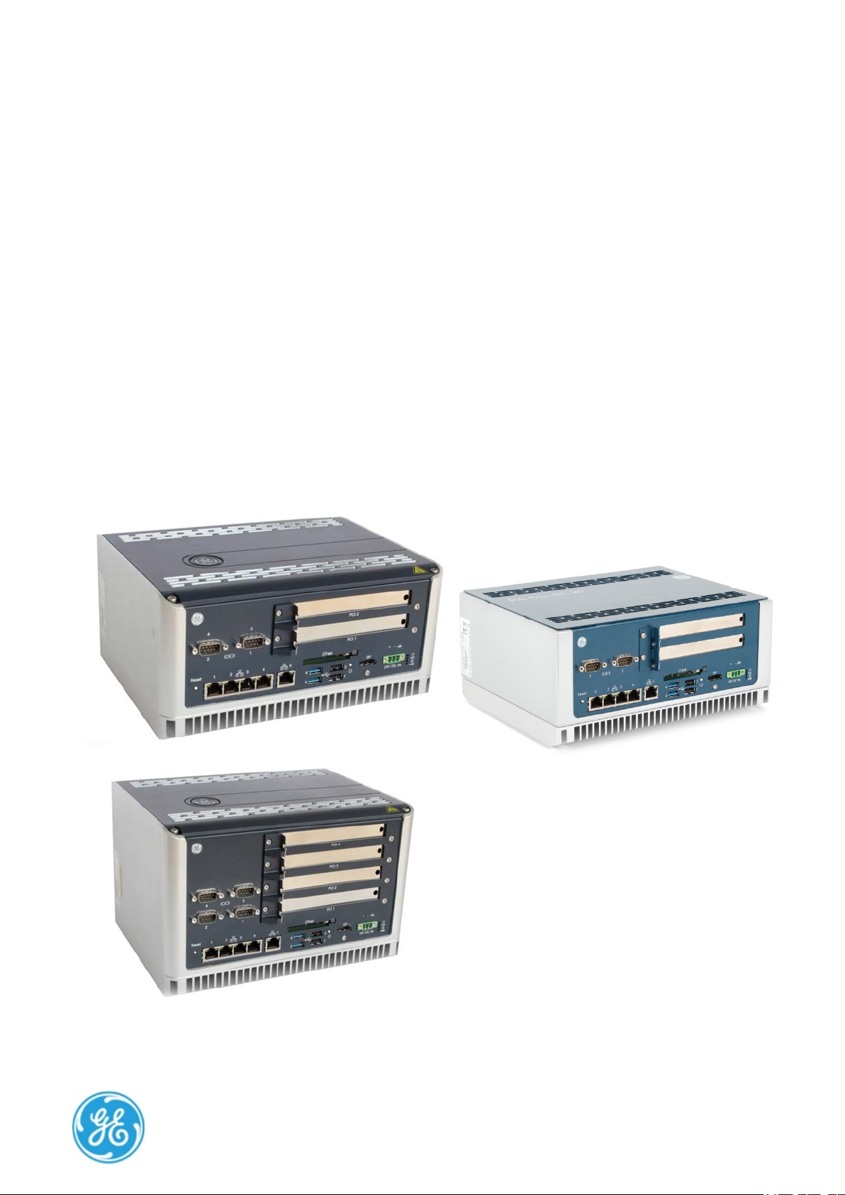
This document defines the RXi Box Industrial PC-XP composed of a bCOM6 COM Express module and the
CEC02 or CEC04 Carrier board.
A Computer-On-Module, or COM, is a module with all components necessary for a bootable host computer,
packaged as a super component. A COM requires a Carrier Board to connect I/O and to power up. COMs are
used to build modular solutions and offer OEMs fast time-to-market with reduced development cost. Like
integrated circuits, they provide OEMs with significant freedom in meeting form-fit-function requirements. For
all these reasons the COM methodology has gained much popularity with OEMs in the embedded industry.
The CEC02/CEC04 Carrier boards are based on the PICMG COM Express Module Base Specification.
The RXi Box IPC-XP is based on industrial grade housing for the Module and Carrier components.
Chapter 1 is the introduction
Chapter 2 describes unpacking and inspection
Chapter 3 is about the installation
Chapter 4 lists the resources
Chapter 5 defines the specifications
Chapter 6 describes the hardware
Chapter 7 informs about support, service and warranty
The following documents also cover items relevant to the RXi Box IPC-XP:
• User’s Manual for AMIBIOS8 Setup
• AMIBIOS8 Check Point and Beep Code List
• AMIBIOS8 Error Messages
PACSystems RXi Box IPC-XP Hardware Reference Manual GFK-2990 7
Internal
Page 8

Typographic Conventions
This manual uses the following notation conventions:
• Italics (sometimes additionally in blue color) emphasize words in text or documentation or chapter titles
or web addresses if underlined.
• Hexadecimal values (base 16) are represented as digits followed by ʹhʹ, for example: 0Ch.
• Hexadecimal values (base 16) are represented as digits preceded by ʹHʹ, for example: H0C.
• Hexadecimal values (base 16) are represented as digits preceded by ʹ$ʹ, for example: $0C.
• Binary values (base 2) are represented as digits followed by ʹbʹ, for example 01b
• The use of a ʹ#ʹ (hash) suffix to a signal name indicates an active low signal. The signal is either true
when it is at logic zero level (voltage close to 0 V) or the signal initiates actions on a high-to-low
transition.
• The use of a ʹ\ʹ (backslash) prefix to a signal name indicates an active low signal. The signal is either true
when it is at logic zero level (voltage close to 0 V) or the signal initiates actions on a high-to-low
transition.
• Text in Courier font indicates a command entry or output from a GE Intelligent Platforms embedded PC
product using the built-in character set.
• Notes, warning symbols and cautions call attention to essential information.
Product Properties
Certification
This product is certified according to:
― CE EN-IEC 60950-1
― EN/IEC 61131-2
For more information about certifications please refer to chapter 6: Specification.
Altitude
Altitude, air pressure and ambient temperature influence the thermal operation of the components described
in this manual. They have been developed and tested at about 500 m (1650 ft.) above sea level at a typical
ambient temperature of 20 °C (68 °F). Because of only marginal variations within a limited range of altitudes
these products operate as specified within altitudes from sea level to 2000 m (~6560 ft.). This is with reference
to temperature ranges of air-cooled versions. GE Intelligent Platforms can assist the user of these components
in planning operation outside this altitude range upon request.
Options
This manual describes the basic product plus all options. Your product may not have all options implemented.
Please verify with your purchase contract which options are implemented. Descriptions of options which are
not implemented obviously do not apply to your product.
Support, Service and Warranty
The manufacturer grants the original purchaser of GE Intelligent Platforms products a warranty of 24 months
from the date of delivery. For details regarding this warranty refer to Terms & Conditions of the initial sale.
PACSystems RXi Box IPC-XP Hardware Reference Manual GFK-2990 8
Internal
Page 9

Please see chapter ʹSupport, Service, and Warranty Informationʹ for further details on repairs and product
support.
For support on the web and product information, visit our website at
http://www.ge-ip.com/
PACSystems RXi Box IPC-XP Hardware Reference Manual GFK-2990 9
Internal
Page 10

Table of Contents
1 Introduction ...............................................................................................................................................................................................................15
1.1 PC Design .........................................................................................................................................................................................................15
1.2 Carrier Design ................................................................................................................................................................................................15
1.3 COM Express Card Design ......................................................................................................................................................................17
2 Unpacking and Inspection ................................................................................................................................................................................19
2.1 Package Contents .......................................................................................................................................................................................19
2.2 Available Accessories ................................................................................................................................................................................20
2.3 Hot Surface .....................................................................................................................................................................................................20
2.4 ESD .......................................................................................................................................................................................................................21
2.5 Initial Inspection ...........................................................................................................................................................................................21
2.6 Unpacking ........................................................................................................................................................................................................22
3 Installation ..................................................................................................................................................................................................................23
3.1 Mounting instruction ..................................................................................................................................................................................23
3.1.1 Flat wall mounting .................................................................................................................................................................................23
3.1.2 Slim Mounting ...........................................................................................................................................................................................27
3.2 Installation preparation ............................................................................................................................................................................29
3.3 General advice ..............................................................................................................................................................................................29
3.4 Required items ..............................................................................................................................................................................................30
3.4.1 Power Supply ............................................................................................................................................................................................30
3.4.2 Keyboard .....................................................................................................................................................................................................30
3.4.3 Video Monitor ...........................................................................................................................................................................................30
3.5 Minimum System Requirements .........................................................................................................................................................31
3.5.1 THE POST TEST .........................................................................................................................................................................................31
3.6 Installation of a PCI board .......................................................................................................................................................................32
3.7 Installation of a Mini PCIe add-on card ...........................................................................................................................................34
3.8 Installation of an Internal Hard Disk Drive .....................................................................................................................................35
3.9 Initial Power-On Operation .....................................................................................................................................................................35
3.10 Entering the UEFI Firmware SETUP ....................................................................................................................................................36
3.11 Exchange the Battery ................................................................................................................................................................................36
4 Hardware ....................................................................................................................................................................................................................39
4.1 Overview for RXE and RXMxx0 based on the carrier CEC04 ...............................................................................................39
4.2 Overview for RXM1x2 based on the carrier CEC02 ...................................................................................................................40
4.3 Interfaces .........................................................................................................................................................................................................41
4.3.1 LEDs ...............................................................................................................................................................................................................42
4.3.2 Power Button ............................................................................................................................................................................................43
4.3.3 Reset Button ..............................................................................................................................................................................................43
4.3.4 Ethernet Interface (Eth1, Eth2, Eth3, Eth4, Eth5; on RXM1x2 Eth1, Eth2, Eth3) .....................................................44
4.3.5 Display Port Interface ...........................................................................................................................................................................45
4.3.6 VGA Interface (RXM1x2 only) ............................................................................................................................................................46
4.3.7 USB 2.0 Connectors (USB1, 2; on RXM1x2 USB1-4) .............................................................................................................47
4.3.8 USB 3.0 Connectors (USB 3,4; not on RXM1x2) ......................................................................................................................48
4.3.9 Power Connector ....................................................................................................................................................................................49
4.3.10 Internal SATA Slot ..............................................................................................................................................................................50
4.3.11 CFast Slot ...............................................................................................................................................................................................50
4.3.12 Serial (COM1,2 or COM1-4; not on RXM1x2) Ports ..........................................................................................................51
4.3.13 Mini PCIe Slot .......................................................................................................................................................................................51
4.3.14 PCIe Slots ...............................................................................................................................................................................................52
4.3.15 PCI Slots ..................................................................................................................................................................................................52
4.4 Additional devices .......................................................................................................................................................................................52
4.4.1 Temperature Sensor .............................................................................................................................................................................52
4.4.2 NVSRAM (Non-Volatile Random-Access Memory; not on RXM1x2) ...........................................................................52
5 Resources ...................................................................................................................................................................................................................53
5.1 Programmable devices ............................................................................................................................................................................53
5.1.1 SMBUS DEVICES ......................................................................................................................................................................................53
PACSystems RXi Box IPC-XP Hardware Reference Manual GFK-2990 10
Internal
Page 11

5.2 ETHERNET ........................................................................................................................................................................................................ 53
5.3 PCIE ports ........................................................................................................................................................................................................ 54
5.4 PCI ROUTING .................................................................................................................................................................................................. 54
6 Specifications ........................................................................................................................................................................................................... 57
6.1 RXi Box IPC-XP Specifications ............................................................................................................................................................... 57
7 Support, Service and Warranty ...................................................................................................................................................................... 61
7.1 Technical Support ....................................................................................................................................................................................... 62
7.2 Support on the Web .................................................................................................................................................................................. 63
7.3 Warranty .......................................................................................................................................................................................................... 63
7.4 Error Report .................................................................................................................................................................................................... 64
8 Glossary ....................................................................................................................................................................................................................... 65
9 Appendix ..................................................................................................................................................................................................................... 67
PACSystems RXi Box IPC-XP Hardware Reference Manual GFK-2990 11
Internal
Page 12

List of Figures
Figure 1: Packaging ..........................................................................................................................................................................................................22
Figure 2; Heat dissipation drawing ..........................................................................................................................................................................23
Figure 3: Flat mounting with mounting plates ..................................................................................................................................................24
Figure 4: Flat wall mounting through the box – illustration .......................................................................................................................25
Figure 5: Flat wall mounting through the wall – illustration ......................................................................................................................26
Figure 6: Clearances slim wall mounting – illustration .................................................................................................................................27
Figure 7: Slim mounting with mounting plate ...................................................................................................................................................28
Figure 8: Installation of a PCIe card ........................................................................................................................................................................33
Figure 9: Installation of Mini-PCIe module ...........................................................................................................................................................34
Figure 10: Internal SATA installation, vendor is subject to change ........................................................................................................35
Figure 11: Removed front panel, view at battery ............................................................................................................................................36
Figure 12: Removed battery ........................................................................................................................................................................................37
Figure 13: Retaining clip with battery ....................................................................................................................................................................37
Figure 14: Hardware Overview ..................................................................................................................................................................................39
Figure 15: Hardware Overview ..................................................................................................................................................................................40
Figure 16: front panel RXE and RXMxx0 ...............................................................................................................................................................41
Figure 17: front panel RXM1x2 ...................................................................................................................................................................................41
Figure 18: front panel LEDs ..........................................................................................................................................................................................42
Figure 19: Power button ................................................................................................................................................................................................43
Figure 20: Reset button ..................................................................................................................................................................................................43
Figure 21: Ethernet Interface ......................................................................................................................................................................................44
Figure 22: Display Port ....................................................................................................................................................................................................45
Figure 23: VGA interface ................................................................................................................................................................................................46
Figure 24: USB 2.0 connectors ...................................................................................................................................................................................47
Figure 25: USB 3.0 connectors ...................................................................................................................................................................................48
Figure 26: Power connector ........................................................................................................................................................................................49
Figure 27: CFast connector ..........................................................................................................................................................................................50
Figure 28: Serial Ports – 2-Slot variant ...................................................................................................................................................................51
Figure 29: Serial Ports – 4-Slot variant ...................................................................................................................................................................51
PACSystems RXi Box IPC-XP Hardware Reference Manual GFK-2990 12
Internal
Page 13

List of Tables
Table 1: Order code and system combinations ............................................................................................................................................... 15
Table 2: Delivery volume ............................................................................................................................................................................................... 19
Table 3: Available accessories ................................................................................................................................................................................... 20
Table 4: Front Power LED ............................................................................................................................................................................................. 42
Table 5: Hard disk activity LED .................................................................................................................................................................................. 42
Table 6: User status LED ............................................................................................................................................................................................... 42
Table 7: Over temperature LED ................................................................................................................................................................................. 42
Table 8: Front Power LED ............................................................................................................................................................................................. 44
Table 9: Ethernet LEDs ................................................................................................................................................................................................... 44
Table 10: Display Port signals .................................................................................................................................................................................... 45
Table 11: VGA ...................................................................................................................................................................................................................... 46
Table 12: USB port 1-2 ................................................................................................................................................................................................... 47
Table 13: USB port 2-3 ................................................................................................................................................................................................... 48
Table 14: Power Connector ......................................................................................................................................................................................... 49
Table 15: Serial Ports ....................................................................................................................................................................................................... 51
Table 16: SMBus Devices .............................................................................................................................................................................................. 53
Table 17: I2C Bus device ............................................................................................................................................................................................... 53
Table 18: PCI Express Port usage ............................................................................................................................................................................. 54
Table 19: PCI Routing ...................................................................................................................................................................................................... 55
Table 20: Environment conditions ........................................................................................................................................................................... 57
Table 21: Shock & vibration parameters ............................................................................................................................................................. 57
Table 22: Maximum height usage ........................................................................................................................................................................... 57
Table 23: Input Power ..................................................................................................................................................................................................... 58
Table 24: Power Consumption RXi Box IPC-XP ................................................................................................................................................. 58
Table 25: Regional areas .............................................................................................................................................................................................. 61
Table 26: Support contact............................................................................................................................................................................................ 62
PACSystems RXi Box IPC-XP Hardware Reference Manual GFK-2990 13
Internal
Page 14

PACSystems RXi Box IPC-XP Hardware Reference Manual GFK-2990 14
Internal
Page 15

Order code
First 6 digits
RXE0x0 X
CEC04
-
0/0 5 2/2
1/0
2/0 a
76
RXE2x0 X
CEC04
043
0/2 5 2/2
1/0
2/0 a
121
RXE4x0 X
CEC04
044
0/4 5 2/2
1/0
2/2
158
RXE5x0 X
CEC04
PERC02
2/0 5 2/2
1/0
2/0 a
121
RXE6x0 X
CEC04
PERC01
2/2 5 2/2
1/0
2/2
158
RXM0x0
X CEC04
-
0/0 5 2/2
1/0
2/0 a
117
RXM1x2
X CEC02
-
1/0 3 0/4
1/1 0 117
RXM2x0
X CEC04
043
0/2 5 2/2
1/0
2/0 a
117
RXM4x0
X CEC04
044
0/4 5 2/2
1/0
2/2
154
RXM5x0
X CEC04
PERC02
2/0 5 2/2
1/0
2/0 a
117
RXM6x0
X CEC04
PERC01
2/2 5 2/2
1/0
2/2
154
1 Introduction
Chapter Scope This chapter describes features, capabilities and compatibilities of the RXi Box IPC-XP,
including the CEC02/CEC04 Carrier board and the bCOM6 module.
1.1 PC Design
The RXi Box IPC-XP consists of a combination of the CEC02/CEC04 carrier board and the bCOM6 COM Express
card, as well a PCI and/or PCI Express riser card and housing w/ heat sink.
There are several system combinations available, for latest info about them please ask our sales team. For a
short summary please check the table below.
Cabinet rugged aluminum
a
On request available with 1x RS232 and 1x RS4xx
Table 1: Order code and system combinations
All RXi Box IPC-XP contain a reset and a power switch, a CFAST slot type1, an internal SSD 2.5 inch drive bay
Cabinet sheet metal
Carrier
Riser card
Number of PCIe / PCI slots
Number of LAN ports
Number of USB 3.0 / USB 2.0
Number of DisplayPort / VGA
Number of Serial RS232/RS4xx
Cabinet height (mm)
and an internal Mini PCIe Slot.
1.2 Carrier Design
This chapter describes the COM Express carrier CEC04 based on PICMG COM Express Module Base
Specification Type 6.
PACSystems RXi Box IPC-XP Hardware Reference Manual GFK-2990 15
Internal
Page 16

The COM Express Carrier CEC04, used in a RXE and the RXMxx0, provides the following core hardware and
firmware resources:
• Support for COM Express Module Type 6
• Functions available on internal connectors
o Mini PCIe slot half/full size
o Almost standard PCIe slot x4 for use with riser card 043/044
o 2 or 4 PCI slots half length, full height on riser card 043/044
o SATA direct drive connect
o BR2032 Lithium Coin Battery
• Functions available on front connector plate
o 24V Power Input with PE ground
o Reset Button
o Power Button
o Display Port
o 4x USB-A connector (2x are USB 3.0 capable with bCOM6L14 only) and 1x internal USB 2.0
o 5x Ethernet connector
o 1x CFast Type 1 bay
o 4x Status LED
The COM Express Carrier CEC02, used in the RXM1x2, provides the following core hardware and firmware
resources:
• Support for COM Express Module Type 6
• Functions available on internal connectors
o Mini PCIe slot half/full size
o Standard PCIe slot x4 for use with slot in cards
o no PCI slots
o SATA direct drive connect
o BR2032 Lithium Coin Battery
• Functions available on front connector plate
o 24V Power Input with PE ground
o Reset Button
o Power Button
o Display Port
o 4x USB-A connector (USB 2.0 capable) and 1x internal USB 2.0
o 2x Ethernet connector
o 1x CFast Type 1 bay
o 4x Status LED
PACSystems RXi Box IPC-XP Hardware Reference Manual GFK-2990 16
Internal
Page 17

1.3 COM Express Card Design
The bCOM6 CPU modules are fully IBM-AT compatible stand-alone PCs. They are equipped with many functions
in a very small form-factor.
The following COM Express CPU modules are available:
bCOM6L14:
o Processor
― Intel® Core™ i7-3555LE Processor 2.5GHz
― Intel® Celeron Processor 1047UE, 1.4GHz
― Intel® Core™ i7-3612QE Processor 2.1GHz
o Chipset
― Intel® Chipset PCH QM77
o System Memory
― One Channel one or two ranks soldered with ECC
― 2 GB or 4GB DDR3 SDRAM with 1066 or 1600 MHz
o UEFI
― SPI interface UEFI (16 Mbit)
o LAN
― One INTEL® internal PCI Express Gigabit controller with 82579 external Phy
― Supports 10Mbps, 100Mbps and 1Gbps data transmission
― IEEE 802.3 (10/100Mbps) and IEEE 802.3ab (1Gbps) compliant
PACSystems RXi Box IPC-XP Hardware Reference Manual GFK-2990 17
Internal
Page 18

PACSystems RXi Box IPC-XP Hardware Reference Manual GFK-2990 18
Internal
Page 19

Item
1
RXi Box IPC-XP
RXi Box Industrial PC XP
2 Unpacking and Inspection
Chapter Scope This chapter covers the suggested inspection and preparation considerations and
background information necessary prior to using the RXi Box IPC-XP. Unpacking, initial
inspection, and first-time operation of the RXi Box IPC-XP are covered. Following the
procedures given in the chapter are recommended, and they will verify proper operation
before the product is integrated into your system.
2.1 Package Contents
Qty.
Table 2: Delivery volume
Purpose
PACSystems RXi Box IPC-XP Hardware Reference Manual GFK-2990 19
Internal
Page 20
Item
ICRXIACCMP01
10 pcs Slim 80 Mount Kits RXi Box IPC-XP
ICRXIACCMP02
10 pcs Flat Mounting Kits RXi Box IPC-XP
ICRXIACCMP03
10 pcs Slim 70 Mount Kits RXi Box IPC-XP
NOTE
Please contact the GE Intelligent Platforms sales department or your sales
representative
NOTE
Accessories are subject to change without notice.
WARNING
Hot Surface!
If
the surface of the
and above
fingers. Install the
2.2 Available Accessories
The following table lists accessories which are available for the RXi Box IPC-XP:
Purpose
Table 3: Available accessories
for latest information on options and accessories.
2.3 Hot Surface
the RXi Box IPC-XP operates by an enhanced ambient temperature more than 50° C
housing, specially the heat sink, can reach a temperature of 70° C
. Therefore be careful and do not touch the RXi Box IPC-XP with bare
RXi Box IPC-XP only in rooms with restricted access.
PACSystems RXi Box IPC-XP Hardware Reference Manual GFK-2990 20
Internal
Page 21
WARNING
DO NOT apply power to the
Doing so may cause further, pos
or shock hazard.
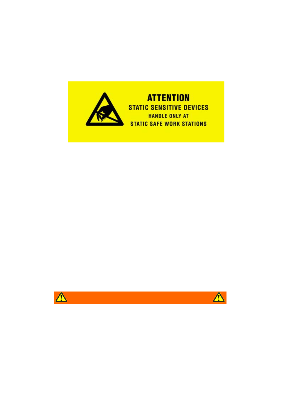
2.4 ESD
Electrostatic Discharge Notice
Electrostatic Discharge Notice The discharge of static electricity, known as Electro Static Discharge or ESD, is a
major cause of electronic component failure. The RXi Box IPC-XP has been packed in a static-safe bag which
protects the IPC from ESD while the IPC is in the bag. Before removing the RXi Box IPC-XP or any other
electronic product from its static-safe bag, be prepared to handle it in a static-safe environment.
You should wear a properly-functioning anti-static strap and ensure you are fully grounded. Any surface upon
which you place the unprotected RXi Box IPC-XP should be static-safe, usually facilitated by the use of antistatic mats. From the time the board is removed from the anti-static bag until it is in the card cage and
functioning properly, extreme care should be taken to avoid ʹzappingʹ the board with ESD. You should be
aware that you could ʹzapʹ the board without you knowing it; a small discharge, imperceptible to the eye and
touch, can often be enough to damage electronic components. Extra caution should be taken in cold and dry
weather when static easily builds up.
Only after ensuring that both you and the surrounding area are protected from ESD, carefully remove the
board or module from the shipping carton by grasping the module on its edges. Place the board, in its
antistatic bag, flat down on a suitable surface. You may then remove the board from the anti-static bag by
tearing the ESD warning labels.
2.5 Initial Inspection
After unpacking the RXi Box IPC-XP, you should inspect it for visible damage that could have occurred during
shipping or unpacking. If damage is observed (usually in the form of bent component leads or loose socketed
components), contact GE Intelligent Platforms for additional instructions. Depending on the severity of the
damage, it may necessary to return the product to the factory for repair.
box if it has visible damage!
sibly irreparable damage, as well as introduce a fire
PACSystems RXi Box IPC-XP Hardware Reference Manual GFK-2990 21
Internal
Page 22

NOTE
Retain all packing material in case of future need.
WARNING
Before installing or removing
external supplies have been turned off
2.6 Unpacking
Please read the manual carefully before unpacking the board or module or fitting the device into your system.
Also adhere to the following:
• Observe all precautions for electrostatic sensitive modules
• If the product contains batteries, please do not place the board on conductive surfaces, antistatic plastic,
or sponge, which can cause shocks and lead to battery or board trace damage.
• Please do not exceed the specified operational temperatures. Note that batteries and storage devices
might also have temperature restrictions.
• Keep all original packaging material for future storage or warranty shipments of the board.
Although the RXi Box IPC-XP is carefully packaged to protect it against the rigors of shipping, it is still possible
that shipping damages can occur. Careful inspection of the shipping carton should reveal some information
about how the package was handled by the shipping service. If evidence of damage or rough handling is
found, you should notify the shipping service and GE Intelligent Platforms as soon as possible.
Figure 1: Packaging
PACSystems RXi Box IPC-XP Hardware Reference Manual GFK-2990 22
Internal
any board, please ensure that the system power and
!
Page 23
3 Installation
Chapter Scope This chapter covers the installation of the RXi Box IPC-XP and initial power-on
operations.
3.1 Mounting instruction
The IPC cooling is designed for wall mounted orientation of the box. The orientation of the heat sink fins
depends on the order code. There are three kinds of fixings possible.
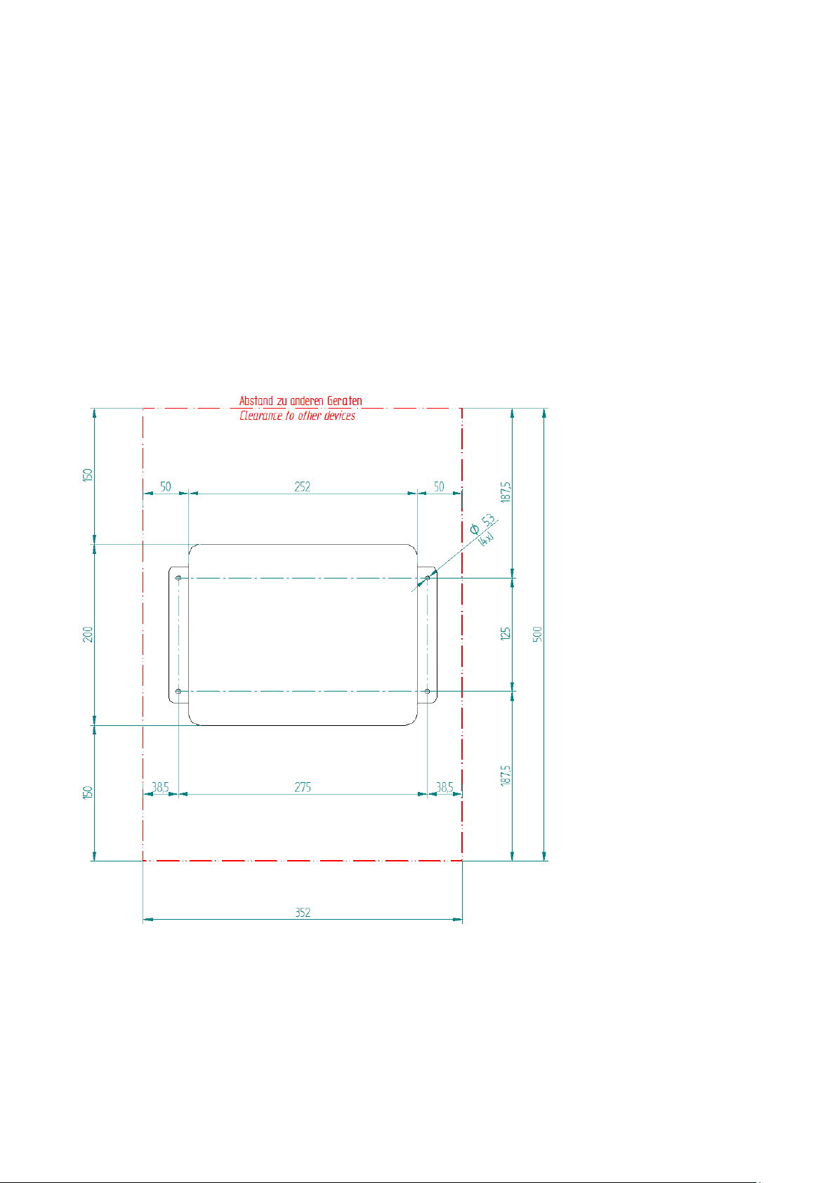
3.1.1 Flat wall mounting
Clearances flat wall mounting
For best heat dissipation observe the minimum clearances from the drawing below.
Figure 2; Heat dissipation drawing
PACSystems RXi Box IPC-XP Hardware Reference Manual GFK-2990 23
Internal
Page 24

NOTE
The mounting plate for 2
Flat Mounting with Mounting Plates
The choice of correct screws depends on the nature of the wall. The mounting plates have 4 drills holes with a
diameter of 5.3 mm. So the maximum screw diameter cannot be higher than 5.2 mm. The head of the screws
have to be smaller than 10 mm, to pass the hole of the top fixing points of the mounting plate.
-slot and 4-slot version will be the same.
Figure 3: Flat mounting with mounting plates
PACSystems RXi Box IPC-XP Hardware Reference Manual GFK-2990 24
Internal
Page 25

Flat wall mounting through the box
The choice of correct screws depends on the nature of the wall. The box has 4 drills with a diameter of 5.1 mm.
So the maximum screw diameter cannot be higher than 5 mm.
Remove the front lid by opening the 4 screws with a screw driver (Torx-20). You will find the 4 holes on the left
and right side inside the box (red marked on the picture below). The thickness of the box is 28 mm at these
locations.
Figure 4: Flat wall mounting through the box – illustration
Take the distances of the holes and the clearances from the drawing in chapter 9.1. After fixing the IPC with
sufficient long screws and torque close the IPC with the front lid with a torque of 1 Nm for the lid screws.
PACSystems RXi Box IPC-XP Hardware Reference Manual GFK-2990 25
Internal
Page 26
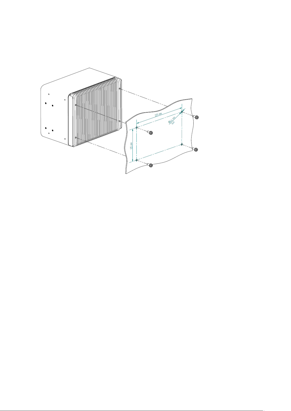
Flat wall mounting through the wall
To fix the IPC with screws from the wall side, you need drill holes in the wall. The positions for the holes can be
taken from the drawing below. The thread in the housing is a M6 with a usable thread length of 15 mm.
Choose the screw length so that a minimum of 10 mm thread will be used. Use a torque of 3.5 Nm.
Figure 5: Flat wall mounting through the wall – illustration
PACSystems RXi Box IPC-XP Hardware Reference Manual GFK-2990 26
Internal
Page 27
Slim 80 mounting plate
Slim 70 mounting plate
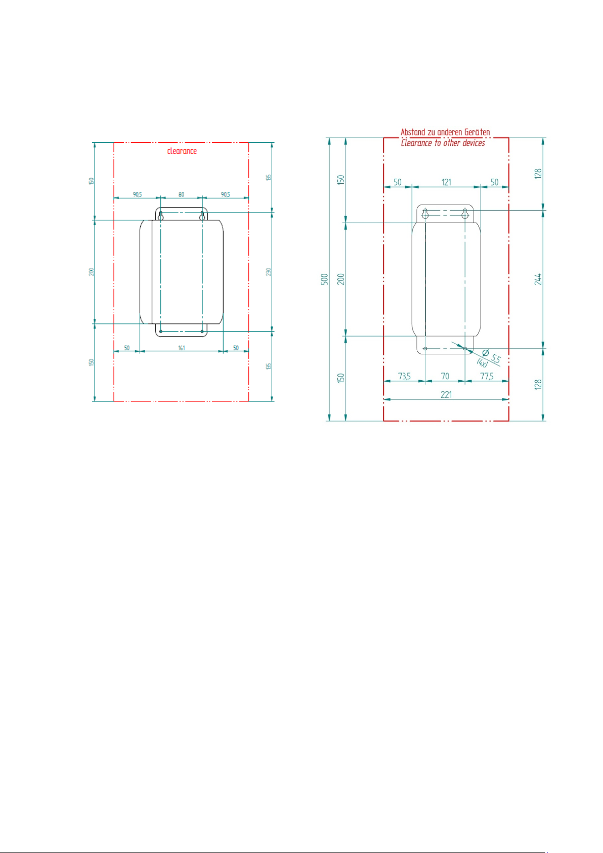
3.1.2 Slim Mounting
Clearances slim wall mounting
For heat dissipation observe the minimum clearances from the drawing below:
ICRXIACCMP01
Figure 6: Clearances slim wall mounting – illustration
ICRXIACCMP03
PACSystems RXi Box IPC-XP Hardware Reference Manual GFK-2990 27
Internal
Page 28

NOTE
The mounting plate for 2
Slim Mounting with Mounting Plate
The choice of correct screws depends on the nature of the wall. The mounting plate has 4 drills holes with a
diameter of 4.5 mm. So the maximal screw diameter cannot be higher than 4.4 mm. The head of the screws
have to be smaller than 10 mm, to pass through the hole of the top fixing points of the mounting plate.
-slot and 4-slot version will be the same.
Figure 7: Slim mounting with mounting plate
PACSystems RXi Box IPC-XP Hardware Reference Manual GFK-2990 28
Internal
Page 29

WARNING
Danger to life through electric shock
Before installing or removing any board, please ensure that the system power and
external supplies have been turned off.
WARNING
Danger to life through electric shock
Before installing or removing any board,
external supplies have been turned off.
3.2 Installation preparation
Use the following steps to install your GE Intelligent Platforms hardware:
!
• Check that the jumpers, if any, are correctly configured for your application.
• Mount the RXi Box IPC-XP very carefully. See also additional advisories below.
• Connect all IO cables.
• Once you are certain that all modules are correctly fitted into the system and all connections have been
made properly, restore the power.
3.3 General advice
Please observe all safety procedures to avoid damaging system and protect operators and users.
!
please ensure that the system power and
PACSystems RXi Box IPC-XP Hardware Reference Manual GFK-2990 29
Internal
Page 30

3.4 Required items
The following items are required to start the board in a standard configuration:
3.4.1 Power Supply
Make sure that the 24V supply is capable of meeting the total power requirements of the RXi Box IPC-XP.
Please refer to chapter ʹSpecificationsʹ for details.
Please make sure that you do not have the power supply turned ON while opening the housing for installing
add-on cards such as PCIe cards or internal SATA drives into the RXi Box IPC-XP.
3.4.2 Keyboard
You should have a USB keyboard for initial system operation of the RXi Box IPC-XP. Depending on your
application, this keyboard may be a standard keyboard, or one which utilizes membrane switches for harsh
environments.
3.4.3 Video Monitor
Any video monitor with native Display Port or a suitable adaptor to Display Port can be used for initial setup.
PACSystems RXi Box IPC-XP Hardware Reference Manual GFK-2990 30
Internal
Page 31

3.5 Minimum System Requirements
The RXi Box IPC-XP has been thoroughly tested, and is nearly ready for usage in the target system. In order to
verify RXi Box IPC-XP operation for the first time, it is suggested that you only configure a minimal system. It is
not necessary to have disk drives, a Flash disk or other accessories connected in order to perform the RXi Box
IPC-XP POWER-ON-SELF-TEST (POST).
3.5.1 THE POST TEST
Each time the computer boots up it must pass the POST (Power-On Self-Test). The following is the procedure of
the POST:
― CPU must exit the reset status mode and thereafter be able to execute instructions
― SPI Flash ROM and NVRAM was readable
― Checksum must be valid, meaning that it must be readable.
― CMOS checksum must be valid, meaning that it must be readable
― CPU must be able to read all forms of memory such as the memory controller, memory bus, and
memory module
― The first 64 KB of memory must be operational and have the capability to be read and written to
and from, and capable of containing the POST code
― I/O bus / controller must be accessible
― I/O bus must be able to write / read from the video subsystem and be able to read all video RAM
If the computer does not pass any of the above tests, the board will fail the POST.
PACSystems RXi Box IPC-XP Hardware Reference Manual GFK-2990 31
Internal
Page 32

ATTENTION
The information described in this chapter
Slot cover, empty
Slot cover screw removed
PCI support_B removed
PCI slot bracket removed
3.6 Installation of a PCI board
is for service technician only!
PCI Boards and PCI Express Boards are installed into the RXi Box IPC-XP as shown by the pictures below for the
RXE2x0. All other configurations including RXM are quite similar in this procedure.
PACSystems RXi Box IPC-XP Hardware Reference Manual GFK-2990 32
Internal
Page 33

PCI card bracket inserted into slot
PCI card inserted into PCIe connector
PCI support_B added
PCI cover screw added
Figure
8: Installation of a PCIe card
PACSystems RXi Box IPC-XP Hardware Reference Manual GFK-2990 33
Internal
Page 34

ATTENTION
The information described in this chapter
Mini PCIe slot full size, empty
Mini PCIe slot half size, empty
Insert Mini-PCIe module
Mounted Mini-PCIe module
Figure
3.7 Installation of a Mini PCIe add-on card
is for service technician only!
Mini PCIe cards are installed into the RXi Box IPC-XP by as shown:
9: Installation of Mini-PCIe module
PACSystems RXi Box IPC-XP Hardware Reference Manual GFK-2990 34
Internal
Page 35

ATTENTION
The information described in this chapter
3.8 Installation of an Internal Hard Disk Drive
is for service technician only!
A 2.5 inch drive bay within the RXi Box IPC-XP may be equipped with a standard SATA drive. The use of Solid
State Drives is recommended. Standard rotating disk drives may be used if they withstand the intended
temperature range within the RXi Box IPC-XP box:
Figure 10: Internal SATA installation, vendor is subject to change
3.9 Initial Power-On Operation
After a few seconds, the RXi Box IPC-XP system BIOS banner will be displayed on the screen. If you have seen
all the on-screen messages to this point, you can be confident that the RXi Box IPC-XP is running properly and
is ready to be set up for your application.
PACSystems RXi Box IPC-XP Hardware Reference Manual GFK-2990 35
Internal
Page 36

ATTENTION
The information described in this chapter
2. Loosen the four captive screws on the IPC’s top
Figure
3.10 Entering the UEFI Firmware SETUP
To enter SETUP during the initial power-on sequence, press the DELETE key during the boot up sequence. Also
see the applicable on-screen messages when prompted.
If the RXi Box IPC-XP does not perform as described above, some damage may have occurred in shipping or
the board is not installed or setup properly. Contact GE Intelligent Platforms technical support as described in
chapter ʹSupport, Service, and Warranty Informationʹ for further instructions.
3.11 Exchange the Battery
is for service technician only!
There is danger of explosion if the battery is incorrectly replaced. Replace only with the same or equivalent to
Rayovac BR2032 type.
Dispose used batteries according to instructions of GE Intelligent Platforms and applicable local regulations.
INSTRUCTION
1. Remove power from the IPC.
cover and remove it.
PACSystems RXi Box IPC-XP Hardware Reference Manual GFK-2990 36
Internal
11: Removed top cover, view at battery
Page 37

3. Remove the RTC battery from the retaining clip.
Figure
WARNING
Use o
explosion!
WARNING
Battery may explode if mistreated. Do not recharge, disassemble, heat above 100°C or
incinerate!
4. Install the new battery in the retaining clip with
Figure
12: Removed battery
f a different type of battery than that specified here may present a risk of fire or
the positive (+) side up.
13: Retaining clip with battery
PACSystems RXi Box IPC-XP Hardware Reference Manual GFK-2990 37
Internal
Page 38

5. Remount the top cover
on the IPC and tighten the four screws to secure it.
PACSystems RXi Box IPC-XP Hardware Reference Manual GFK-2990 38
Internal
Page 39

COM Express Module
DC-
DC Conversion
PCIe Switch
Pericom
508
10/100/1000
Ethernet
MAC/PHY
(i210)
10/100
/1000
Ethernet
MAC/
PHY
(
i210)
10/
100/1000
Ethernet
MAC/PHY
(i210)
10/100
/1000
Ethernet
MAC/PHY
(i210)
Magnetics
Riser Connector
UART
4-
ch
x4
PCIe Gen1
x1 PCIe Gen1
mini PCI-e
x1
PCIe Gen1
x1 PCIe Gen1
x
1 PCIe Gen1
Optocoupl
Transc
RS-232
Transc
RS-232
Transc
RS
-422
/
RS
485
Transc
RS-422
/
RS485
Opto
-
coupl
Power
Conn
DB-9DB-9
DB-9DB-9
optional
optional
RJ-45
DP
CFast
USB
USB
USB
USB
Magnetics
RJ-45
Magnetics
RJ-45
Magnetics
RJ-45
Magnetics
RJ-
45
FAN
(optional)
Fan
Controller
PCI slot
PCIe
to PCI
Switch
PCI slot
PCI slot
PCI slot
FPGA
NVRAM
NVRAM Option
2 or 4 PCI slots
4 Hardware
Chapter Scope This chapter describes the hardware of the RXi Box IPC-XP.
4.1 Overview for RXE and RXMxx0 based on the carrier CEC04
Figure 14: Hardware Overview
PACSystems RXi Box IPC-XP Hardware Reference Manual GFK-2990 39
Internal
Page 40

4.2 Overview for RXM1x2 based on the carrier CEC02
Figure 15: Hardware Overview
PACSystems RXi Box IPC-XP Hardware Reference Manual GFK-2990 40
Internal
Page 41

4.3 Interfaces
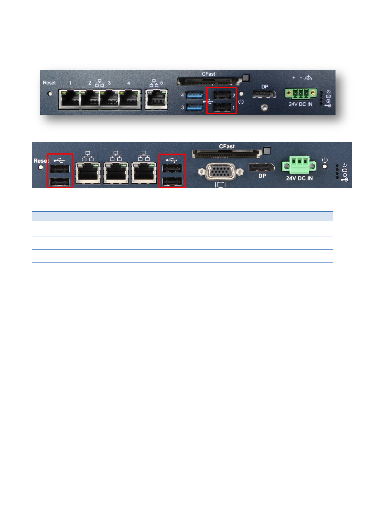
Depending on the used carrier two basic variants of the front panel exist. Top is always shown the standard
panel on a CEC04. Below can be found the panel of the CEC02 used in the RXM1x2.
RXE and RXMxx0:
Figure 16: front panel RXE and RXMxx0
RXM1x2:
Figure 17: front panel RXM1x2
PACSystems RXi Box IPC-XP Hardware Reference Manual GFK-2990 41
Internal
Page 42
Some power is applied
red
Valid power is applied, CPU is in any standby or off state
amber
Valid power, CPU is powered
green
No hard disk activity
off
Hard disk activity on SATA or CFlash
amber
User Status LED a
User Status LED (amber by default)
Temperature below limit
off
Temperature above limit
red (default temperature limit is set to 85 °C)
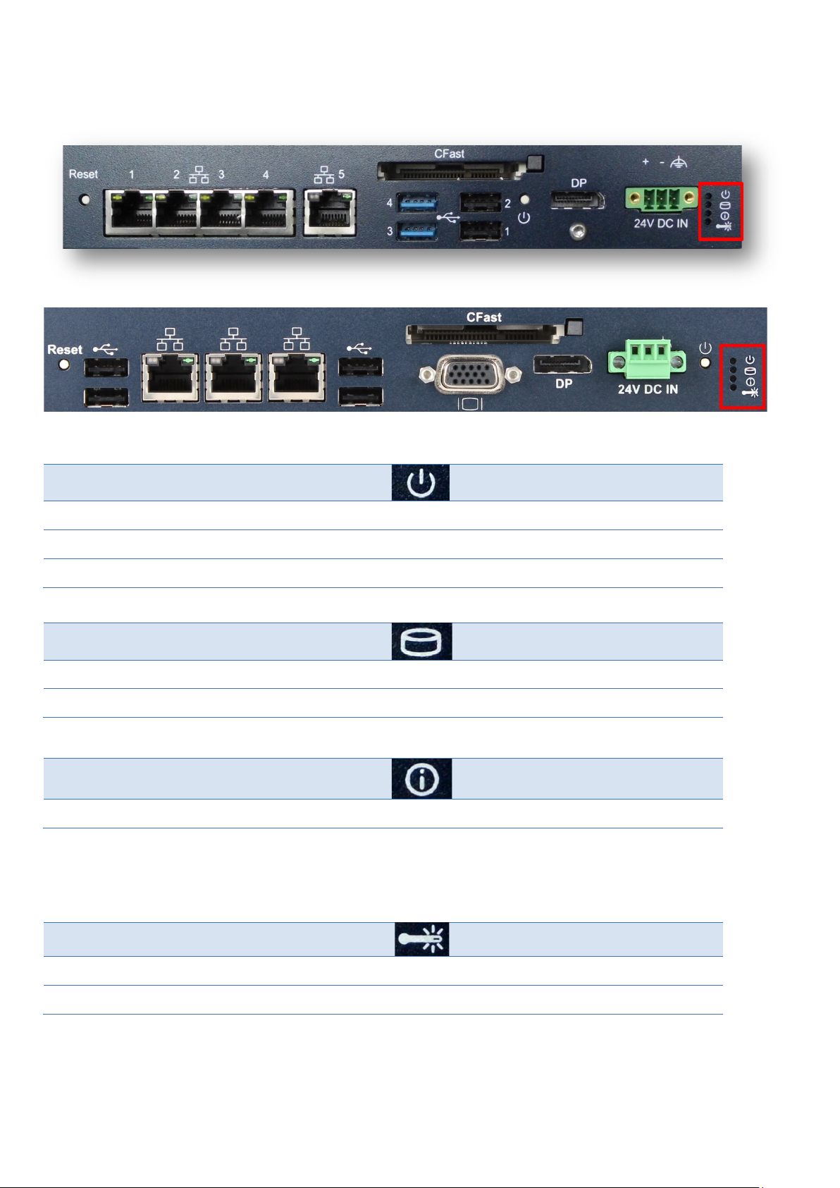
4.3.1 LEDs
The RXi Box IPC-XP has a set of status LEDs for indicating various functions.
Figure 18: front panel LEDs
Status.
Table 4: Front Power LED
Status.
Table 5: Hard disk activity LED
Status.
a
On RXM1x2 this LED shows the status of the battery coin cell within the system. It lights red when the battery is exhausted. After
replacement of the battery, the red LED must be reset within UEFI SETUP.
Table 6: User status LED
Status.
Table 7: Over temperature LED
PACSystems RXi Box IPC-XP Hardware Reference Manual GFK-2990 42
Internal
Page 43
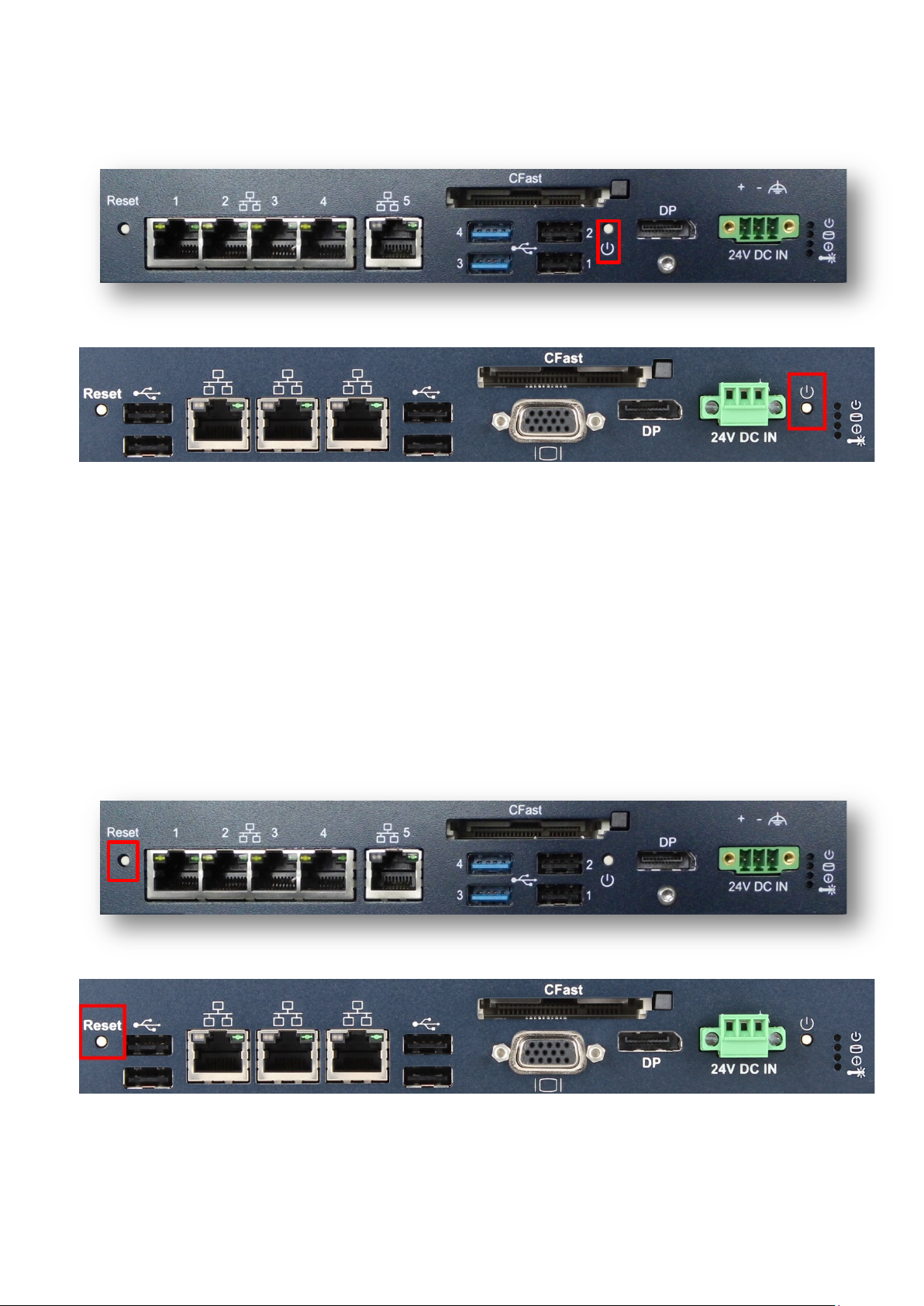
4.3.2 Power Button
There is a Power Button at the front panel. Please use an appropriate tool for operation when needed.
Figure 19: Power button
A short push of the power button triggers the operating system shutdown (Power State S5). If the operating
system doesn’t react, holding the button pushed for more than 5 seconds forces the RXi Box IPC-XP to shut
down immediately without operating system support.
State S5 (Soft-Off-Mode) will switch off the CPU core power and hold the RXi Box IPC-XP in reset. The state S5 is
indicated with an amber Power LED. At this state it is possible to reactivate the RXi Box IPC-XP with a short
press of the Power Button. The CPU core voltage is switched on and the boards restart.
4.3.3 Reset Button
There is a Reset button at the front panel. Please use an appropriate tool for resetting the RXi Box IPC-XP.
Figure 20: Reset button
PACSystems RXi Box IPC-XP Hardware Reference Manual GFK-2990 43
Internal
Page 44

Name 1000base
TxD+
LP_DA+
1
TxD-
LP_DA-
2
RxD+
LP_DB+
3
NC
LP_DC+
4
NC
LP_DC-
5
RxD-
LP_DB-
6
NC
LP_DD+
7
NC
LP_DD-
8
Function
Right green LED
Off
No link
Left yellow LED
Off
No activity
4.3.4 Ethernet Interface (Eth1, Eth2, Eth3, Eth4, Eth5; on RXM1x2 Eth1, Eth2, Eth3)
Figure 21: Ethernet Interface
The Ethernet interfaces require usage of CAT 5 cable for proper operation with 100/1000BaseT.
Name 10/100base
Table 8: Front Power LED
Two LEDs (green and yellow) are integrated in each of the RJ45 connector. These LEDs indicate the link status
and activity of the interface.
LED
On
Link is active
On, blink
Table 9: Ethernet LEDs
Tx/Rx activity
PACSystems RXi Box IPC-XP Hardware Reference Manual GFK-2990 44
Internal
Page 45

TxD0+/-
1/3
TxD1+/-
4/6
TxD2+/-
7/9
TxD3+/-
10/12
AUXSEL
13
CLK/AUX+
15
DAT/AUX-
17
HTPLG
18
n.c.
14
DP_VCC a
20
GND
2, 5, 8, 11, 16, 19
4.3.5 Display Port Interface
A Display Port provides signals for connecting either a suitable monitor or adaptor to lots of other display
standards.
Figure 22: Display Port
Name
Table 10: Display Port signals
a
DP_VCC is fused with 2 A, but for normal operation don’t exceed 1 A at this pin.
PACSystems RXi Box IPC-XP Hardware Reference Manual GFK-2990 45
Internal
Page 46

RED1
1
GREEN1
2
BLUE1
3 4
GND
5
GND
6
GND
7
GND
8
VGA_VCC 1)
9
GND
10 11
VGA1_DDCData
12
VGA1_HSYNC
13
VGA1_VSYNC
14
VGA1_DDCClock
15
4.3.6 VGA Interface (RXM1x2 only)
A VGA port provides signals for connecting a suitable monitor.
Figure 23: VGA interface
Name
Table 11: VGA
1) VGA_VCC is fused with 2 A, but for normal operation don’t exceed 1 A at this pin.
PACSystems RXi Box IPC-XP Hardware Reference Manual GFK-2990 46
Internal
Page 47
1
USB-
2
USB+
3
GND
4
4.3.7 USB 2.0 Connectors (USB1-2; on RXM1x2 USB1-4)
Four USB channels are available at standard USB Type A connectors. Each pair of them is fused with 2 A, but
for normal operation don’t exceed 0.5 A per connector.
Figure 24: USB 2.0 connectors
Name
FUSE_VCCa
Table 12: USB port 1-2
a
the FUSE_VCC pin has a 2 A fuse. For normal operation don’t exceed 0.5A current per connector.
PACSystems RXi Box IPC-XP Hardware Reference Manual GFK-2990 47
Internal
Page 48

1
USB-
2
USB+
3
GND
4
SSRX-
5
SSRX+
6
GND
7
SSTX-
8
SSTX+
9
4.3.8 USB 3.0 Connectors (USB 3-4; not on RXM1x2)
Four USB channels are available at standard USB Type A connectors. Each pair of them is fused with 2 A, but
for normal operation don’t exceed 0.5 A per connector. The blue USB connector supports USB 3.0 when used
with the bCOM6L14 CPU module.
Figure 25: USB 3.0 connectors
Name
FUSE_VCCa
Table 13: USB port 3-4
a
the FUSE_VCC pin has a 2 A fuse. For normal operation don’t exceed 0.5A current per connector.
PACSystems RXi Box IPC-XP Hardware Reference Manual GFK-2990 48
Internal
Page 49

power +
1
power -
2
Frame GND
3
NOTE
Never use a power supply generating a
PE ground. It will be shortened if any external device is connected to the
XP
4.3.9 Power Connector
The power inlet into the RXi Box IPC-XP is a PHOENIX CONTACT MC 1,5/ 3-GF-3,81connector. The corresponding
plug is a type MC 1,5/ 3-STF-3,81from PHOENIX CONTACT.
Figure 26: Power connector
Name
Table 14: Power Connector
The power input is filtered internally on the RXi Box IPC-XP. Behind the filter the power minus is connected to
GND of all connections within the RXi Box IPC-XP. Therefore when using a power supply with a supply reference
to PE ground, please connect the +24V to power plus and the GND to power minus.
-24V output if the positive supply is related to
RXi Box IPC-
.
The power input is secured with two 5A blow fuses. If the Input power exceeds the limits, these fuses will be
blown to protect all circuitry within the RXi Box IPC-XP. Please contact GE Intelligent Platforms for a suitable
replacement.
PACSystems RXi Box IPC-XP Hardware Reference Manual GFK-2990 49
Internal
Page 50

NOTE
Drives with rotating media may be used if they with
range inside the
4.3.10 Internal SATA Slot
Inside the RXi Box IPC-XP there is a bay for mounting a standard SATA 2.5 inch drive.
stand the intended temperature
RXi Box IPC-XP. The use of Solid State Disk is recommended.
4.3.11 CFast Slot
On the front of the RXi Box IPC-XP there a CFast Type I flash slot is available. Standard CFast cards can be used
for storage of data or the operating system. The device is connected to a standard SATA port of the COM
module.
Figure 27: CFast connector
PACSystems RXi Box IPC-XP Hardware Reference Manual GFK-2990 50
Internal
Page 51
F
F
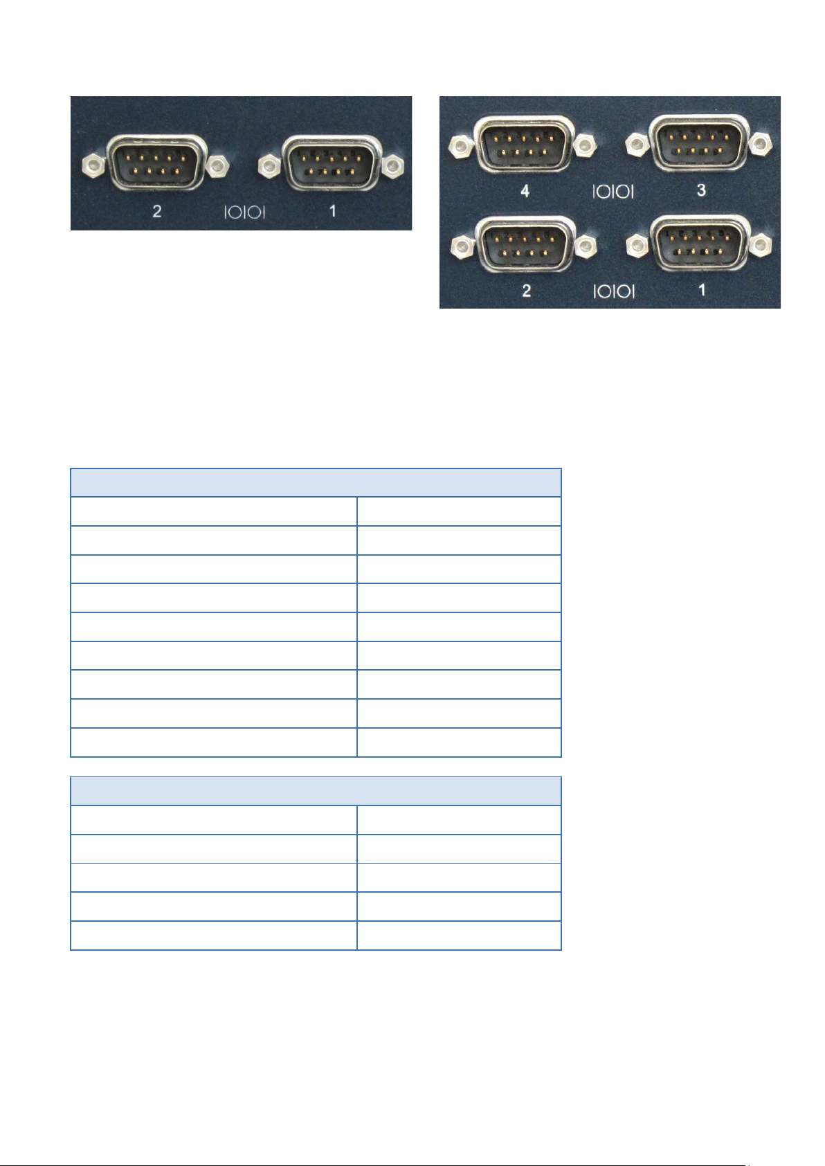
4.3.12 Serial (COM1,2 or COM1-4; not on RXM1x2) Ports
(CP;
igure 28: Serial Ports – 2-Slot variant
igure 29: Serial Ports – 4-Slot variant
The 2-slot variant of the RXi Box IPC-XP is provided with two serial ports. The two serial ports are RS232 on 9pin
D-connectors for local terminals or peripheral communication. On request a combination of RS232 and
RS422/485 is orderable too. The 4-slot variant is equipped with four serial ports. Serial ports 1 & 2 are RS232
and serial ports 3 & 4 are RS422/485
RS232 pin
DCD 1
RxD 2
TxD 3
DTR 4
GND 5
DSR 6
RTS 7
CTS 8
RI 9
RS422/485
Rx+ 1
Rx- 2
Tx+ 3
Tx- 4
GND 5
Table 15: Serial Ports
4.3.13 Mini PCIe Slot
On the carrier there is a Mini PCIe Slot supporting half size and full size add-on cards. The supported PCIe
speed is 2.5GBit/s (Gen 1).
PACSystems RXi Box IPC-XP Hardware Reference Manual GFK-2990 51
Internal
Page 52

4.3.14 PCIe Slots
Depending on the system configuration there are up to two PCIe slots in the RXi Box IPC-XP. In a RXM1x2 the
supported PCIe speed is 2.5GBit/s (Gen 1) and the link width is x4. In a RXx5 or RXx6 the supported PCIe speed
is 5.0GBit/s (Gen 2) and the link width is x1 in Slot 1 and x2 in Slot 2.
4.3.15 PCI Slots
Depending on the system configuration there are up to 4 PCI Slots. The PCI speed is 33MHz. The PCI width is
32bit. The signaling voltage is 3.3V. The slot is 5V type keyed thus signaling that these slots are 5V signal level
tolerant.
4.4 Additional devices
4.4.1 Temperature Sensor
Temperature sensors are integrated in the CPU module and on the carrier. The sensor on the carrier shows the
local ambient temperature within the RXi Box IPC-XP.
The sensors of the CPU and Carrier are programmed to take actions to protect the devices from over-heating.
The CPU temperature sensor has a catastrophic protection which shut down the CPU core voltage if the die
temperature reaches its final limits.
4.4.2 NVSRAM (Non-Volatile Random-Access Memory; not on RXM1x2)
The RXi Box IPC-XP contains a NVSRAM (mounted on the riser card) which is automatically backed up when the
PC is switched off or loses its power supply. It is not supplied with the battery power therefore an exhausted
Lithium coin will not cause any loss of data stored in that NVSRAM. For accessing the NVSRAM please ask our
support team.
PACSystems RXi Box IPC-XP Hardware Reference Manual GFK-2990 52
Internal
Page 53

PI6C20800S
1101 110x
PCIe Clock Buffer on CEC04
DB106
1101 010x
PCIe Clock Buffer on CEC02 (RXM1x2)
LM29245
1001 100x
Temperature sensor on bC6L14 (via EC controller)
24C08
1010 000x
SPD on bC6L14
LM95245
0101 001x
Temperature sensor on CEC04
24c512
1010 000x
Factory EEprom of bC6L14
24c64
1010 111x
Factory EEprom of CEC02/CEC04
5 Resources
Chapter Scope This chapter lists the hardware and firmware resources of the CEC04 carrier and the
bCOM6 module.
5.1 Programmable devices
5.1.1 SMBUS DEVICES
Device Address Function
Table 16: SMBus Devices
Device Address Function
Table 17: I2C Bus device
5.2 ETHERNET
The Ethernet controllers provide internal configuration EEPROMs which also contains the MAC address.
PACSystems RXi Box IPC-XP Hardware Reference Manual GFK-2990 53
Internal
Page 54

PEG_T/RX[3..0]+/-
5 port PCIe Switch to
Ethernet Controllers
PCIe slot x4
PCIe port x4 lane
PCIE_T/RX[0]+/-
PCIe slot for riser card
Ethernet Controller 1
PCIe ports x1 lane
PCIE_T/RX[1]+/-
PCIe to Serial controller
Ethernet Controller 2
PCIe ports x1 lane
PCIE_T/RX[2]+/-
Mini PCIe slot
Mini PCIe slot
PCIE_T/RX[3]+/-
Not used on CEC04
Not used on CEC02
On bCOM6L14
Host Bridge
internal
8086
0154
0/00/0
PEG
PCle Switch
8086
0151
0/01/0
Graphics
Internal
8086
0156
0/02/0
USB xHCI Controller
8086
1E31
0/14/0
ME Interface
8086
1E3A
0/16/0
LAN Controller
8086
1502
0/19/0
USB EHCI Controller #2
8086
1E2D
0/1A/0
PCIe 1
Riser card 043
8086
1E10
0/1C/0
PCIe 2
PCIe Serial
8086
1E12
0/1C/1
PCIe 3
Mini PCle
8086
1E14
0/1C/2
USB EHCI Controller #1
8086
1E26
0/1D/0
LPC
FPGA
8086
1E55
0/1F/0
SATA #0,1
8086
1E03
0/1F/2
SMBUS
8086
1E22
0/1F/3
On CEC02 (RXM1x2)
Ether #0
front
8086
1533
4/00/0
Ether #1
front
8086
1533
5/00/0
Mini PCle
6/00/0
PCIe Slot
7/00/0
On CEC04 (RXE, RXM0x0)
PCIe Switch Host
PEG
12D8
0508
1/00/0
PCIe Switch Port#1
Ether #4
12D8
0508
2/01/0
PCIe Switch Port#2
Ether #3
12D8
0508
2/02/0
PCIe Switch Port#3
Ether #2
12D8
0508
2/03/0
PCIe Switch Port#4
Ether #1
12D8
0508
2/04/0
5.3 PCIE ports
The PCIe ports are provided by the COM Express Module. Following PCIe allocation is provided:
COM Express Signal Device on CEC04 Device on CEC02 (RXM1x2) Description
Table 18: PCI Express Port usage
5.4 PCI ROUTING
The PCI routings in an RXi Box IPC-XP are defined as followed:
Function Connected to Vendor Device Bus/Dev/Func
PACSystems RXi Box IPC-XP Hardware Reference Manual GFK-2990 54
Internal
Page 55

Ether #4
front
8086
1533
3/00/0
Ether #3
front
8086
1533
4/00/0
Ether #2
front
8086
1533
5/00/0
Ether #1
front
8086
1533
6/00/0
PCIe Serial
Serial
12D8
7954
9/00/0
Mini PCle
A/00/0
On Riser card 043/044
(RXx2x0, RXx4x0)
PCIe to PCI bridge
PCI Slots
12D8
E113
7/00/0
NVSRAM
1533
3AD2
8/05/0
PCI Slot #1
8/06/0
PCI Slot #2
8/07/0
PCI Slot #3
8/08/0
PCI Slot #4
8/09/0
Riser card PERC01/02
(RXx6x0, RXx5x0)
PCIe Switch
PCIe Slots
10B5
8606
7/00/0
PCIe Slot #1
8/00/0
PCIe Slot #2
9/00/0
PCIe to PCI bridge
PCI Slots
12D8
E113
A/00/0
NVSRAM
1533
3AD2
B/05/0
PCI Slot #1
B/06/0
PCI Slot #2
B/07/0
Function Connected to Vendor Device Bus/Dev/Func
Table 19: PCI Routing
PACSystems RXi Box IPC-XP Hardware Reference Manual GFK-2990 55
Internal
Page 56

PACSystems RXi Box IPC-XP Hardware Reference Manual GFK-2990 56
Internal
Page 57

Level A
High Temperature
RXxxxxQ, 35W CPU
+50 °C
Low Temperature
- Operating
0 °C
Relative Humidity
- Storage, Operating
Level A
Vibration
- Acceleration
1 grms
Shock
- Duration
11 ms
Level A
Maximum height
- Storage
6 Specifications
Chapter Scope This chapter gives some useful information when using an RXi Box IPC-XP for the first
time. It might be also useful to read this chapter carefully, when problems came up in
using the RXi Box IPC-XP.
6.1 RXi Box IPC-XP Specifications
Temperature
Ambient temperatures and humidity values for the RXi Box IPC-XP:
Order – Code Temp.
- Storage
- Operating
RXxxxxE, RXxxxxN, 17W CPU
RXxxxxF, 25W CPU
- Storage
a
For more temperature information and extended temperature range please ask our support team.
Table 20: Environment conditions
a
+70 °C
+60 °C
+55 °C
-40 °C
up to 95% non-condensing
The RXi Box IPC-XP is designed to meet these shock and vibration values:
- Spectrum
- half sine or saw tooth
3 to 100 Hz
20 g
Table 21: Shock & vibration parameters
Maximum height usage for the RXi Box IPC-XP is specified in the table below:
- Operating
Table 22: Maximum height usage
PACSystems RXi Box IPC-XP Hardware Reference Manual GFK-2990 57
Internal
2000 m
Page 58

Nominal Input
(Volt)
Input Range
(Volt)
Max. Input Ripple
(Volt)
24
21.6 – 26.4
+/- 0.2
RXM1N2N0J100A, Intel®
RXx6N0F0G134A, Intel® Core™
RXx2N0Q0F102A, Intel® Core™
RXx2N0F0F102A, Intel® Core™
DOS idle
40°C
13W
25W
18W
22W
UEFI SETUP or shell
40°C
13W
26W
18W
23W
VxWorks idle
40°C
12W
21W
21W
18W
Windows 7 idle
40°C
21W
18W
Windows 7 HeavyLoad Tool
40°C
43W
34W
Windows 7 prime95 V28.7
40°C
15W
41W
Windows 7 HeavyLoad Tool
100°C
57W
38W
Windows 7 prime95 V28.7
100°C
17W
48W
Humidity
• Operating: 10 % to 95 % rH, non-condensing
Power Entry
The RXi Box IPC-XP works from a single main power rail with a nominal value of +24V (+/-10 %). The nominal
voltage should be 24Vdc, SELV according to IEC60950-1.
Table 23: Input Power
Operation CPU temperature Power
Celeron® 1047UE, 1.4GHz, 4GB
Table 24: Power Consumption RXi Box IPC-XP
i7-3555LE, 2.5GHz, 4GB
i7- 3612QE, 2.1GHz, 8GB
i7-3555LE, 2.5GHz, 8GB
The consumption values include USB keyboard/mouse and a SSD hard disk. For each linked Ethernet channel you
have to add 0.5 W.
PACSystems RXi Box IPC-XP Hardware Reference Manual GFK-2990 58
Internal
Page 59

Power Budget for add-on devices
The CEC02 and CEC04 support a power budget for USB devices, SATA devices and add-on cards of total 25W.
For the add-on cards on the riser card any share between +12V, 5V and 3.3V power consumption is possible up
to 20W maximum for all two/four cards together.
The -12V current limit is 100mA per Slot according to the PCI specification.
Battery
The RXi Box IPC-XP contains a BR2032 lithium coin. The maximum current drawn by the bC6L14 is 6uA.
Depending on the operating hours and temperature, the estimated battery life is 2 to 10 years. Battery current
is not drawn when the RXi Box IPC-XP is supplied with 24V.
Regulatory
• CE
• EMC: CE and designed to meet FCC Part 15 Class B, DNV
Box
• Dimensions
o The RXi Box IPC-XP dimensions are 252 mm x 207 mm
o The RXi Box IPC-XP height of a 0-slot RXE configuration is 76 mm (RXM: 117mm)
o The RXi Box IPC-XP height of a 1 or 2-slot RXE configuration is 121 mm (RXM: 117 mm)
o The RXi Box IPC-XP height of a 4-slot RXE configuration is 158 mm (RXM: 154 mm)
• Weight
o The empty RXi Box IPC-XP has a total weight of about 4.3 kg (RXE version with four slots), 3.8 kg
(RXE version with two slots) and 3.2 kg (RXE version without slot). RXM versions are around 100g
less. Add-On cards, hard disk drive and other accessories have to be added if implemented.
PACSystems RXi Box IPC-XP Hardware Reference Manual GFK-2990 59
Internal
Page 60

PACSystems RXi Box IPC-XP Hardware Reference Manual GFK-2990 60
Internal
Page 61

world-wide
EU
Europe, Russia, Near East, India, Africa
US
Americas & Pacific Rim (Japan, Korea, China, Philippines, AUS, NZ)
7 Support, Service and Warranty
Chapter Scope The following section describes GE Intelligent Platforms’ product support program. There
are two regional support headquarters and regional customer centers. In this chapter
you will find information about our product warranty terms and details about what
action to take if you experience a problem with the product.
Geographical Regions
World-wide headquarter of GE Intelligent Platforms, Inc. is at
GE Intelligent Platforms Inc.
2500 Austin Drive
Charlottesville, VA 22911
U.S.A.
Web: www.ge-ip.com
Europe, Middle East and Africa headquarter of GE Intelligent PLATFORMS Inc. is at
GE Intelligent Platforms GmbH & Co. KG
Memminger Str. 14
Augsburg, D-86 159
Germany
GE Intelligent Platforms, Inc. uses two regional headquarters for the purpose of support, service, RMA returns
and other functions.
Regional areas:
WW
Table 25: Regional areas
PACSystems RXi Box IPC-XP Hardware Reference Manual GFK-2990 61
Internal
Page 62

Monday through Thursday
8:00 – 17:00 (CET)
Friday
8:00 – 16:00 (CET)
Phone +49-821-5034-170
Fax +49-821-5034-119
E-Mail support.augsburg.ip@ge.com
7.1 Technical Support
If you should have a problem with a GE Intelligent Platforms product: Free technical support is available by
phone, fax or email. Telephone support is available at main locations or at the regional center where the
product was bought.
Germany
Table 26: Support contact
PACSystems RXi Box IPC-XP Hardware Reference Manual GFK-2990 62
Internal
Page 63

7.2 Support on the Web
For support and information, visit our website at
http://www.ge-ip.com/
Information for components, corresponding driver software, etc. can also be found at the following locations:
AMD Corp. www.amd.com
American Megatrends www.ami.com
Fedora www.fedora.redhat.com
IBM Corp. www.ibm.com
Intel Corp. www.intel.com
Linear Technology www.linear-tech.com
Microsoft Corp. www.microsoft.com
Freescale Corp. www.freescale.com
Novell www.novell.com
NVIDIA www.nvidia.com
Pericom www.pericom.com
PCI Industrial Computer Manufacturing Group www.picmg.org
PLX Technology www.plxtech.com
QNX Software Systems www.qnx.com
Red Hat www.redhat.com
VITA www.vita.com
Wind River Systems www.windriver.com
7.3 Warranty
For detailed warranty information, visit our website at
http://www.ge-ip.com/
PACSystems RXi Box IPC-XP Hardware Reference Manual GFK-2990 63
Internal
Page 64

7.4 Error Report
For error reports and RMA (Return Material Authorization) forms contact support at these email addresses:
repairs.augsburg.ip@ge.com
In case of difficulties provide at least the information listed below to an appropriate support center or on their
web site as listed above:
• RMA Number, if applicable
• Product & Serial Number
• Part Number
• Version
• Contact: Name & Phone Number
• Detailed Description of the Problem/Defect
PACSystems RXi Box IPC-XP Hardware Reference Manual GFK-2990 64
Internal
Page 65

8 Glossary
APIC Advanced Programmable Interrupt Controller
BIT Built-In Test
CE Conformite Europeenne (European conformity)
CFast A variant of CompactFlash. CFast supports a higher maximum transfer rate than
current Compact Flash cards.
COM Computer On Module
DVI Digital Video Interface
ECC Error Correction Checking
EEPROM Electrically Erasable Programmable Read-Only Memory
EMI Electro-Magnetic Interference
ESD Electro-Static Discharge
EU European Union
FCC Federal Communication Commission (USA)
GPIO General Purpose I/O
GT Giga Transfers
I/O Input / Output
IRQ Interrupt ReQuest
LAN Local Area Network
LED Light Emitting Diode
LV Low Voltage
NVRAM Non-Volatile Random-Access Memory
PCH Peripheral Controller Hub
PCI Peripheral Component Interconnect
PCIe Peripheral Component Interconnect Express
POST Power-On Self Test
RMA Return Material Authorization
RTC Real-Time Clock
SATA Serial Advanced Technology Attachment
SBC Single Board Computer
SMB System Management Bus
SPI Serial Peripheral Interface
SV Standard Voltage
UART Universal Asynchronous Receiver Transmitter
UEFI Universal Extensible Firmware Interface
ULV Ultra Low Voltage
USB Universal Serial Bus
VGA Video Graphics Array
PACSystems RXi Box IPC-XP Hardware Reference Manual GFK-2990 65
Internal
Page 66

PACSystems RXi Box IPC-XP Hardware Reference Manual GFK-2990 66
Internal
Page 67

9 Appendix
GNU LESSER GENERAL PUBLIC LICENSE
Version 3, 29 June 2007
Copyright © 2007 Free Software Foundation, Inc. <http://fsf.org/>
Everyone is permitted to copy and distribute verbatim copies of this license document, but changing it is
not allowed.
This version of the GNU Lesser General Public License incorporates the terms and conditions of version 3
of the GNU General Public License, supplemented by the additional permissions listed below.
0. Additional Definitions.
As used herein, “this License” refers to version 3 of the GNU Lesser General Public License, and the
“GNU GPL” refers to version 3 of the GNU General Public License.
“The Library” refers to a covered work governed by this License, other than an Application or a
Combined Work as defined below.
An “Application” is any work that makes use of an interface provided by the Library, but which is not
otherwise based on the Library. Defining a subclass of a class defined by the Library is deemed a mode of
using an interface provided by the Library.
A “Combined Work” is a work produced by combining or linking an Application with the Library. The
particular version of the Library with which the Combined Work was made is also called the “Linked
Version”.
The “Minimal Corresponding Source” for a Combined Work means the Corresponding Source for the
Combined Work, excluding any source code for portions of the Combined Work that, considered in
isolation, are based on the Application, and not on the Linked Version.
The “Corresponding Application Code” for a Combined Work means the object code and/or source code
for the Application, including any data and utility programs needed for reproducing the Combined Work
from the Application, but excluding the System Libraries of the Combined Work.
1. Exception to Section 3 of the GNU GPL.
You may convey a covered work under sections 3 and 4 of this License without being bound by section 3
of the GNU GPL.
2. Conveying Modified Versions.
If you modify a copy of the Library, and, in your modifications, a facility refers to a function or data to be
supplied by an Application that uses the facility (other than as an argument passed when the facility is
invoked), then you may convey a copy of the modified version:
• a) under this License, provided that you make a good faith effort to ensure that, in the event an
Application does not supply the function or data, the facility still operates, and performs whatever part of
its purpose remains meaningful, or
• b) under the GNU GPL, with none of the additional permissions of this License applicable to that copy.
PACSystems RXi Box IPC-XP Hardware Reference Manual GFK-2990 67
Internal
Page 68

3. Object Code Incorporating Material from Library Header Files.
The object code form of an Application may incorporate material from a header file that is part of the
Library. You may convey such object code under terms of your choice, provided that, if the incorporated
material is not limited to numerical parameters, data structure layouts and accessors, or small macros,
inline functions and templates (ten or fewer lines in length), you do both of the following:
• a) Give prominent notice with each copy of the object code that the Library is used in it and that the
Library and its use are covered by this License.
• b) Accompany the object code with a copy of the GNU GPL and this license document.
4. Combined Works.
You may convey a Combined Work under terms of your choice that, taken together, effectively do not
restrict modification of the portions of the Library contained in the Combined Work and reverse
engineering for debugging such modifications, if you also do each of the following:
• a) Give prominent notice with each copy of the Combined Work that the Library is used in it and that the
Library and its use are covered by this License.
• b) Accompany the Combined Work with a copy of the GNU GPL and this license document.
• c) For a Combined Work that displays copyright notices during execution, include the copyright notice for
the Library among these notices, as well as a reference directing the user to the copies of the GNU GPL
and this license document.
• d) Do one of the following:
o 0) Convey the Minimal Corresponding Source under the terms of this License, and the
Corresponding Application Code in a form suitable for, and under terms that permit, the user to
recombine or relink the Application with a modified version of the Linked Version to produce a
modified Combined Work, in the manner specified by section 6 of the GNU GPL for conveying
Corresponding Source.
o 1) Use a suitable shared library mechanism for linking with the Library. A suitable mechanism is
one that (a) uses at run time a copy of the Library already present on the user's computer system,
and (b) will operate properly with a modified version of the Library that is interface-compatible
with the Linked Version.
• e) Provide Installation Information, but only if you would otherwise be required to provide such
information under section 6 of the GNU GPL, and only to the extent that such information is necessary to
install and execute a modified version of the Combined Work produced by recombining or relinking the
Application with a modified version of the Linked Version. (If you use option 4d0, the Installation
Information must accompany the Minimal Corresponding Source and Corresponding Application Code. If
you use option 4d1, you must provide the Installation Information in the manner specified by section 6 of
the GNU GPL for conveying Corresponding Source.)
5. Combined Libraries.
You may place library facilities that are a work based on the Library side by side in a single library
together with other library facilities that are not Applications and are not covered by this License, and
convey such a combined library under terms of your choice, if you do both of the following:
• a) Accompany the combined library with a copy of the same work based on the Library, uncombined with
any other library facilities, conveyed under the terms of this License.
• b) Give prominent notice with the combined library that part of it is a work based on the Library, and
explaining where to find the accompanying uncombined form of the same work.
PACSystems RXi Box IPC-XP Hardware Reference Manual GFK-2990 68
Internal
Page 69

© 2013 - 2016 GE Intelligent Platforms
EXPRESSLY DISCLAIMED.
GE Intelligent Platforms
Additional Resources
6. Revised Versions of the GNU Lesser General Public License.
The Free Software Foundation may publish revised and/or new versions of the GNU Lesser General
Public License from time to time. Such new versions will be similar in spirit to the present version, but
may differ in detail to address new problems or concerns.
Each version is given a distinguishing version number. If the Library as you received it specifies that a
certain numbered version of the GNU Lesser General Public License “or any later version” applies to it,
you have the option of following the terms and conditions either of that published version or of any later
version published by the Free Software Foundation. If the Library as you received it does not specify a
version number of the GNU Lesser General Public License, you may choose any version of the GNU
Lesser General Public License ever published by the Free Software Foundation.
If the Library as you received it specifies that a proxy can decide whether future versions of the GNU
Lesser General Public License shall apply, that proxy's public statement of acceptance of any version is
permanent authorization for you to choose that version for the Library.
Embedded Systems, Inc. All rights reserved.
* indicates a trademark of GE Intelligent
Platforms, Inc. and/or its affiliates. All other
trademarks are the property of their respective
owners.
Confidential Information - This document
contains Confidential/Proprietary Information
of GE Intelligent Platforms, Inc. and/or its
suppliers or vendors. Distribution or
reproduction prohibited without permission.
THIS DOCUMENT AND ITS CONTENTS ARE
PROVIDED "AS IS", WITH NO REPRESENTATIONS
OR WARRANTIES OF ANY KIND, WHETHER
EXPRESS OR IMPLIED, INCLUDING BUT NOT
LIMITED TO WARRANTIES OF DESIGN,
MERCHANTABILITY, OR FITNESS FOR A
PARTICULAR PURPOSE. ALL OTHER LIABILITY
ARISING FROM RELIANCE UPON ANY
INFORMATION CONTAINED HEREIN IS
Information Centers
Americas:
1 800 322 3616 or 1 256 880 0444
Asia Pacific:
86 10 6561 1561
Europe, Middle East and Africa:
Germany +49 821 5034-0
UK +44 1327 359444
For more information, please visit the
GE Intelligent Platforms Embedded
Systems web site at:
www.ge-ip.com/
 Loading...