

Page 1
GE
For Public Disclosure
Automation & Controls
Programmable Control Products
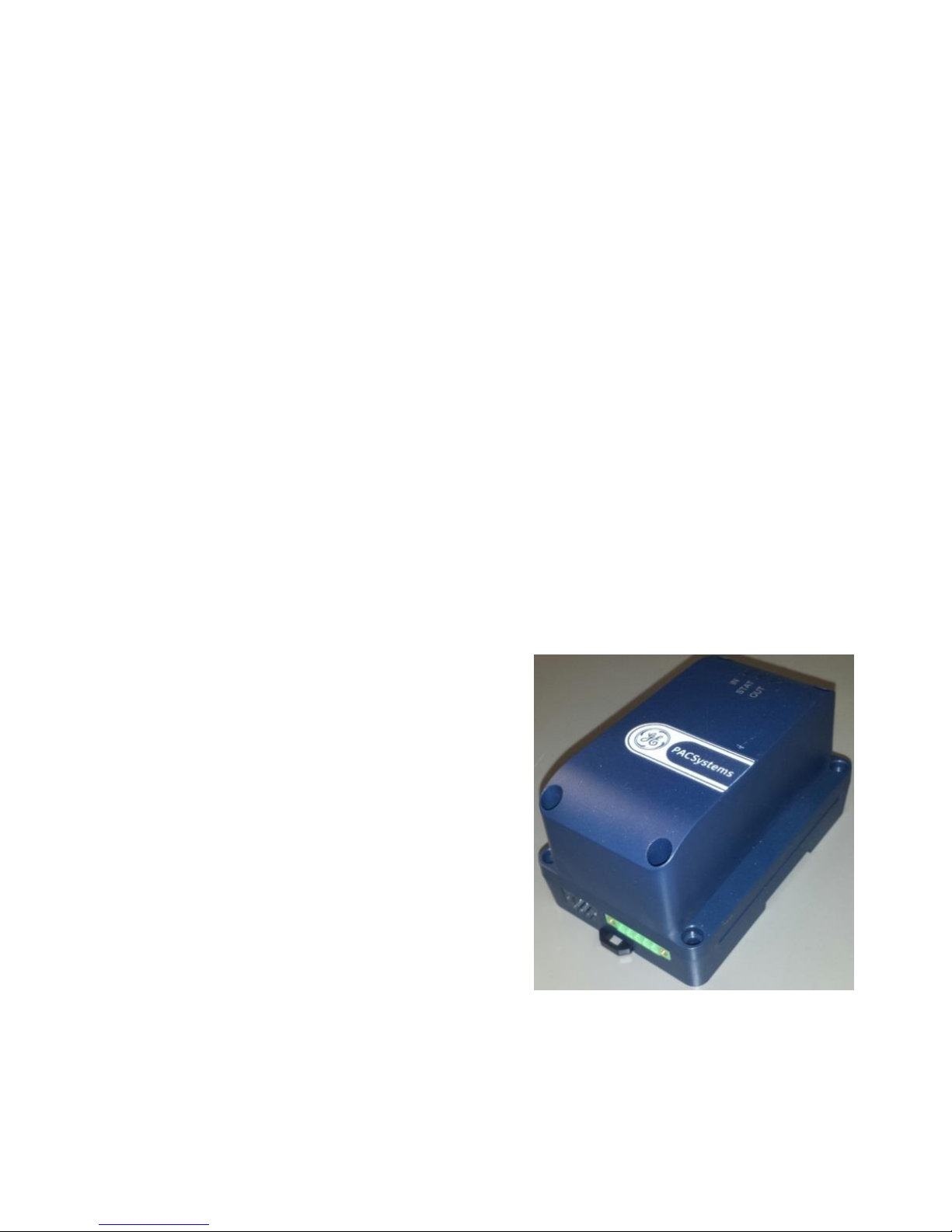
PACSystems* RX3i
Rackless Energy Pack
IC695ACC403
Quick Start Guide
GFK-3000A
July 2018
Page 2

GFK-3000A IC695ACC403 Quick Start Guide ii
Contents
1 Overview .............................................................................. 1
2 Hardware Installation ................................................... 2
2.1 Mounting the Energy Pack on a DIN Rail .. 2
2.2 Panel-Mounting the Energy Pack ................ 3
3 Cable Connections ......................................................... 4
3.1 Connect Input Power to Energy Pack ........ 5
3.2 Connecting the Energy Pack to the
Controller ............................................................................ 6
4 Grounding ........................................................................... 7
5 Initial Power-up ................................................................ 8
6 LED and Status Indications ........................................ 9
6.1 LED Indications: Special Cases ................... 10
6.2 Energy Pack Status Bit Operation ............ 10
7 Replacing the CapPack Module ............................ 11
8 Firmware Updates ....................................................... 12
8.1 LED Indications for Firmware Updates ... 12
9 Additional Information .............................................. 13
Page 3
1 July 2018 GFK-3000A
1 Overview
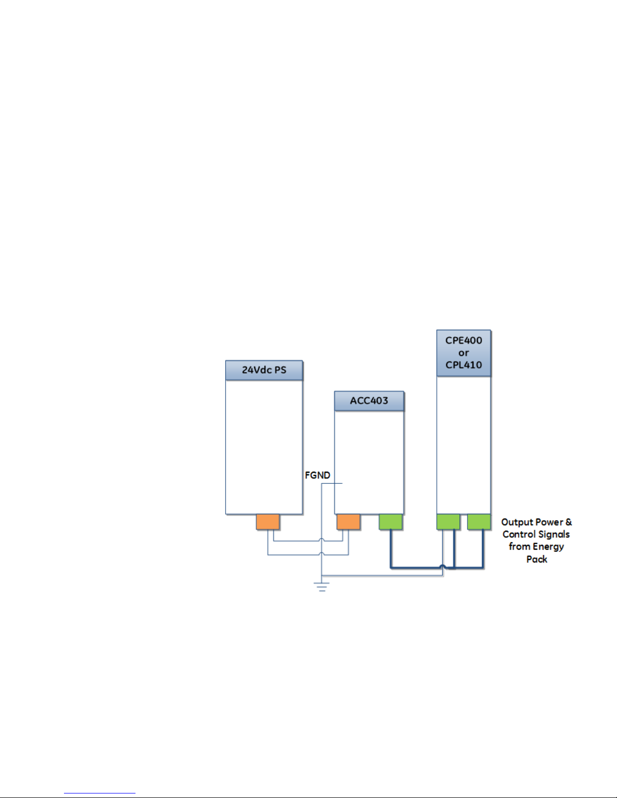
An Energy Pack is used in conjunction with a Controller
to preserve user memory in the Controller during power
fluctuations or outages.
If system power is lost, the Energy Pack maintains power
long enough for a Controller to write its user memory
contents to non-volatile memory. When system power is
restored, the user memory is restored if the Controller is
configured to power up from RAM.
Figure 1: Interconnect Wiring Diagram
Page 4

GFK-3000A IC695ACC403 Quick Start Guide 2
Ordering Information
IC695ACC403
Energy Pack. Includes base,
CapPack module and Energy Pack
to Controller cable.
IC695ACC413
Replacement CapPack module.
IC695CBL003
Replacement 0.6m (24”) Energy
Pack to Controller cable.
2 Hardware Installation
The Energy Pack can be mounted on a standard EN50022
DIN rail or an equipment panel. It is designed to be
mounted adjacent to the Controller and connected to the
Controller using the provided cable (IC695CBL003).
Heat dissipation: When mounting the Energy Pack,
allow a minimum clearance of 25.4mm (1 inch) on all four
sides of the unit (right, left, top and the bottom).
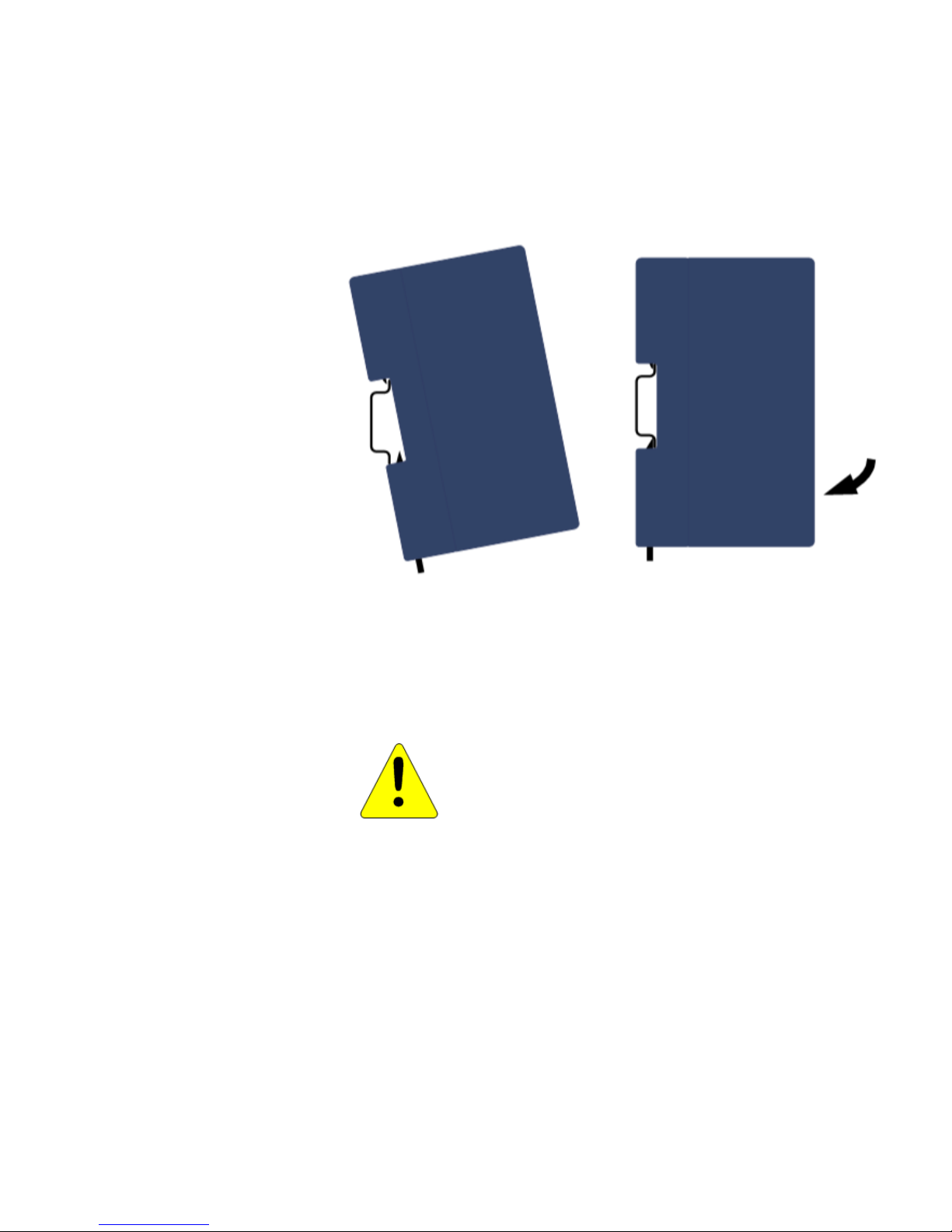
2.1 Mounting the Energy Pack on a DIN Rail
The Energy Pack snaps easily onto the DIN rail. No tools
are required.
1) Incline Energy Pack so that top edge of plastic
recess (Figure 2) engages top of DIN rail
2) Swivel the Energy Pack so that bottom spring-
loaded plastic clip engages bottom of DIN rail.
3) Listen for click as plastic clip springs back,
securing the Energy Pack onto the DIN rail.
Page 5
3 July 2018 GFK-3000A
Figure 2: Snap Mount to DIN Rail
2.2 Panel-Mounting the Energy Pack
Recommended fasteners:
Four M4-0.7 machine screws with minimum length
of 25mm (or 8-32, 1” min. length) and nuts.
CAUTION
Over tightening the mounting screws could
crack the plastic housing.
Page 6
GFK-3000A IC695ACC403 Quick Start Guide 4
3 Cable Connections
Figure 3: Input Power and Output Power
/Control Connections
Page 7

5 July 2018 GFK-3000A
3.1 Connect Input Power to Energy Pack
IMPORTANT
Before connecting input power, see complete
installation instructions in the PACSystems
Controllers: Battery and Energy Pack Manual,
GFK-2741E or later.
You will need:
▪ A 24Vdc, 72W SELV power supply
▪ A power cord with 18 AWG (0.82mm
2
) copper wires
▪ An 18 AWG (0.82mm
2
) copper wire for frame ground
▪ An input power terminal block – provided
(Weidmuller part number 1748010000)
▪ A small flat-head screwdriver (such as a 1.4mm
jeweler’s screwdriver)
1. Using the power cord, connect the power supply
output to the Energy Pack’s input power terminal
block.
To insert the wires in the power terminal block
connector, you may need to use the small
screwdriver to release the spring clamp on the
terminal block.
Recommended wire stripping length is
7mm (0.28 in).
Page 8

GFK-3000A IC695ACC403 Quick Start Guide 6
Figure 4: Energy Pack Input Power Mating
Connector (bottom view)
2. Insert the plug into the Energy Pack’s Input
Power connector and securely tighten the
attaching screws.
3.2 Connecting the Energy Pack to the
Controller
With power to the system turned off, use the
supplied cable (IC695CBL003) to connect the
output of the Energy Pack (green connector) to
the 24Vdc input on the Controller (3-pin green
connector) and to the serial communication link
(using the 5-pin green connector). Refer to
Figure 5.
Page 9

7 July 2018 GFK-3000A
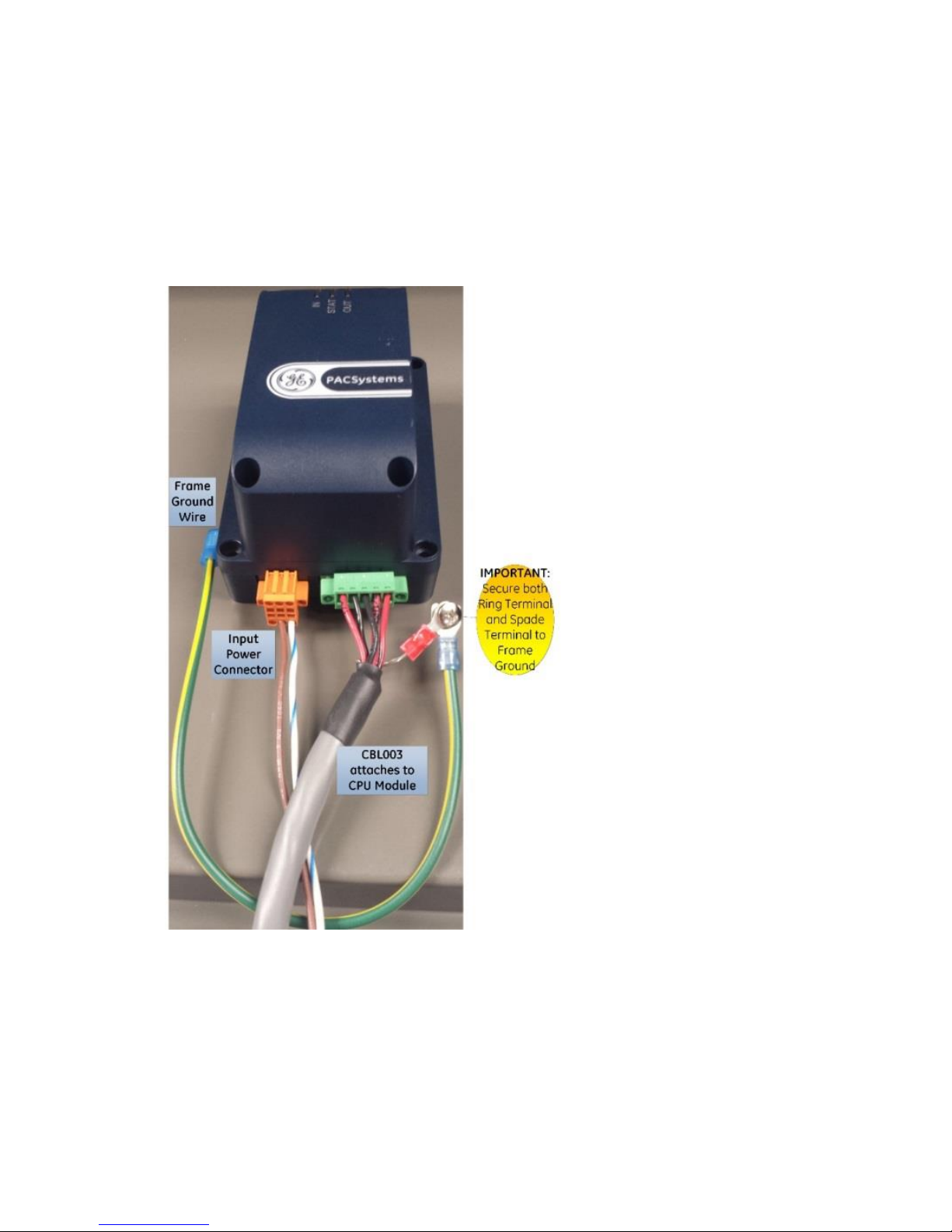
4 Grounding
Proper grounding of this device is essential. All ground
wires must be as short as possible and terminated at the
same grounding point.
Figure 5: Frame Ground Connection
Page 10

GFK-3000A IC695ACC403 Quick Start Guide 8
5 Initial Power-up
When 24Vdc power is first applied to the Energy Pack,
the power-up process goes through the following steps:
1. The IN LED turns on green.
2. The Energy Pack performs a self-diagnostic
test. If this test passes, output power to the
Controller is turned on and the OUT LED turns
on green.
3. Charging of the CapPack begins and the STAT
LED blinks green.
4. When charging of the CapPack is complete, the
STAT LED turns on solid green and the Energy
Pack signals to the controller that it can start
run-time operation. The Controller will not start
running its application until the Energy Pack
signals that it is fully charged.
Figure 6: LEDs on CAP Pack
Page 11

9 July 2018 GFK-3000A
6 LED and Status Indications
The LEDs on the Energy Pack indicate its status.
LED
LEDState
Energy Pack Status
IN
Green,
solid
Input power is applied and within the
specified range.
Red,
solid
Input power is outside the specified
range.
Off
Input power is not applied.
STAT
Green,
blinking
CapPack Charging in progress. No
faults.
Green,
solid
CapPack is fully charged and no faults.
Amber,
blinking
CapPack is nearing end-of-life. The
CapPack must be replaced soon.
Backup is still guaranteed.
Red,
blinking
Internal fault: Cycle power to the
Energy Pack. If this does not clear the
fault, contact Technical Support and
replace the Energy Pack.
Red,
solid
CapPack has reached end-of-life.
Replace the CapPack. Backup is
not
guaranteed.
Off
No power applied.
OUT
Green,
solid
Output power is within the specified
range.
Red,
solid
Output power is present but outside
spec.
Off
Output power is not present.
Page 12

GFK-3000A IC695ACC403 Quick Start Guide 10
6.1 LED Indications: Special Cases
All LEDs blinking in unison: See
Firmware Updates, page 12.
6.2 Energy Pack Status Bit Operation
As shown in the table below, a CPU application program
can automatically monitor the status of the attached
Energy Pack via %S0014 (PLC_BAT) and %SA0011
(LOW_BAT). For more details, refer to the chapter on
Diagnostics in PACSystems RX7i and RX3i CPU
Programmer’s Reference Manual, GFK-2950.
PLC_BAT
(%S0014)
LOW_BAT
(%SA0011)
Energy Pack Status
0
0
Energy Pack connected and
operational (may be
charging)
1
1
Energy Pack not connected
or has failed
0
1
Energy Pack is nearing its
end-of-life and should be
replaced.
Page 13

11 July 2018 GFK-3000A
7 Replacing the CapPack Module
The CapPack can be removed and replaced while
power is applied to the Energy Pack (hot swapped.)
CAUTION
When hot swapping CapPacks, do not
cycle power until the new CapPack is fully
charged and operational. Cycling power
before the STAT LED on the CapPack is solid
green can result in Controller memory not
being preserved.
Do not hot remove/insert the CapPack during
the firmware update process.
1. Loosen the four screws on the CapPack and
carefully pull the CapPack off the base.
2. Install the new CapPack on the base, first
engaging the module-to-base connectors
and then pressing the CapPack into place.
CAUTION
Over tightening the mounting screws could
crack the plastic housing.
3. Use the four screws provided to secure the
CapPack to the base.
4. When the CapPack is first inserted, the STAT
LED blinks green while the CapPack is
charging. Do not remove power to the
Energy Pack while the CapPack is charging
Page 14

GFK-3000A IC695ACC403 Quick Start Guide 12
because this could result in Controller
memory not being preserved.
The Energy Pack LEDs and the Controller
status bits indicate when charging is
complete and the Energy Pack is ready to
support backup.
5. To remove a Failed Battery fault and clear
the battery status bits, clear the Controller
fault table.
For details on status bit operation, refer to
the PACSystems RX7i and RX3i CPU
Reference Manual, GFK-2222 (rev. Y or later).
8 Firmware Updates
The firmware for the Energy Pack is automatically
updated by the Controller. At power-up, the
Controller checks the version of Energy Pack firmware
to verify compatibility with the Controller firmware. If
an update is needed, the Controller performs it
automatically.
8.1 LED Indications for Firmware Updates
Firmware Update
Mode
All three LEDs blink green
Failed to Load
Firmware
All three LEDs blink red
Page 15

13 July 2018 GFK-3000A
9 Additional Information
PACSystems RX7i and RX3i CPU Reference Manual,
GFK-2222Y or later
PACSystems Controllers: Battery and Energy Pack
Manual, GFK-2741E or later
PACSystems RX3i / Series 90-30 Installation and
Maintenance Requirements, GFK-2975
For user manuals, product updates and other
information go to the Support website,
www.geautomation.com and refer to Controllers and IO,
RX3i Rackless Controllers.
Page 16

GE
Contact Information
Americas: 1-800-433-2682 or
1-434-978-5100
Global regional phone numbers are available
on our
web site
www.geautomation.com
©2016-2018 General Electric Company.
All Rights Reserved
*Trademark of General Electric Company
and/or its subsidiaries.
All other trademarks are property of their
respective holders.
GFK-3000A
Page 17

 Loading...