

Page 1

GE
Automation & Controls
Programmable Control Products
PACSystems* IC695CPE400
RX3i 1.2GHz 64MB
Rackless CPU w/Field Agent
Quick Start Guide
GFK-3002A
October 2017
g
Page 2

Page 3

i IC695CPE400 Rackless CPU w/Field Agent Quick Start Guide GFK-3002A
Contents
User Features ................................................................................................................. 1
Switches ........................................................................................................... 4
Displays and Indicators (LEDs) ......................................................................... 4
Front-Panel Ethernet Ports ............................................................................... 7
Serial COM Port ................................................................................................ 8
Video Display Port ............................................................................................ 8
Field Agent Port ................................................................................................ 8
Energy Pack Connector .................................................................................... 9
Input Power Connector ..................................................................................... 9
Removable Data Storage Device (RDSD) ......................................................... 9
Hardware Installation................................................................................................. 10
Initial Checks ...................................................................................................10
Installation .......................................................................................................10
Installation in Hazardous Areas ........................................................................12
Connect to Power Supply .................................................................................13
Grounding ........................................................................................................14
Module Start-up ........................................................................................................... 15
You Will Need: .................................................................................................15
Basic Start-up Steps: .......................................................................................16
Configuration ............................................................................................................... 17
Backwards Compatibility ..................................................................................17
PROFINET Controller Configuration ................................................................17
Field Agent Configuration .................................................................................18
4.3.1. Start the Embedded Field Agent (EFA) ............................................................18
4.3.2. Log into the Web Console ................................................................................18
4.3.3. Configure the Network .....................................................................................20
Redundancy Configuration ...............................................................................24
Additional Information ............................................................................................... 25
Page 4

Page 5
1 IC695CPE400 Rackless CPU w/Field Agent Quick Start Guide GFK-3002A
User Features
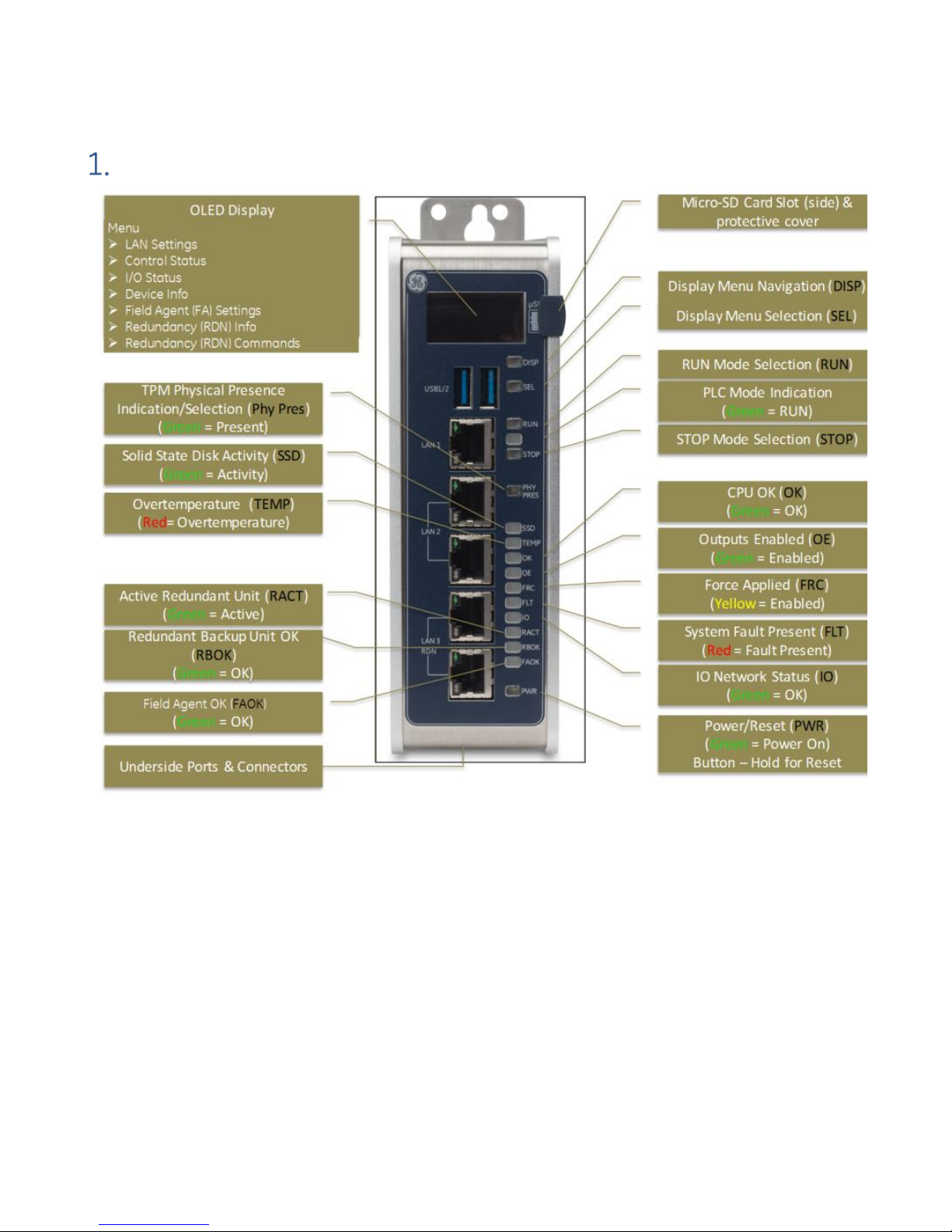
Figure 1: CPE400 Features at a Glance
The PACSystems* RX3i CPE400, part of GE’s Industrial Internet Control System, is the
industry’s first outcome optimizing controller. It augments real-time deterministic
control with Field Agent technology, delivering near real time advice through market
analysis, fleet and enterprise data, or asset/process knowledge to optimize the
outcomes that today’s businesses require. The Predix™ enabled CPE400 provides
reliable, secure communication and analytics using either cloud-based or edgebased outcome optimizing apps. Controls can now be programmed to dynamically
influence business outcomes, generate new forms of revenue, and improve
profitability.
Page 6

GFK-3002A October 2017 2
• The stand-alone CPE400 uses a 1.2GHz quad-core microprocessor and real-time
hypervisor technology to run real time deterministic control applications
concurrently with Field Agent technology without any adverse impact of one
over the other.
• A built-in RX3i PLC:
o User may program in Ladder Diagram, Structured Text, Function Block
Diagram, or C.
o Contains 64Mbytes of configurable data and program memory.
o Supports auto-located Symbolic Variables that can use any amount of user
memory.
o Reference table sizes include 32k bits for discrete %I and %Q and up to 32k
words each for analog %AI and %AQ. Bulk memory (%W) also supported for
data exchanges.
o Supports up to 512 program blocks. Maximum size for a block is 128KB.
• Field Agent technology is a platform for securely applying Predix applications
and secure connectivity to the Predix Cloud as well as running edge apps.
Running the Field Agent concurrently with the real-time control applications
allows the CPE400 to rapidly leverage external data. External monitoring may be
used to analyze and optimize entire business operations. The analysis can then
be used to dynamically adjust real-time industrial controls to align with changing
business objectives in today’s Industrial Internet age.
• Supports four independent 10/100/1000 Ethernet LANs. Three are located on the
front panel, as shown in Figure 1. LAN1 attaches via the upper, dedicated RJ 45
connector. LAN2 and LAN3 each attach via a pair of internally-switched RJ 45
connectors. The fourth LAN, labeled EFA (Embedded Field Agent), is located on
the underside (Figure 2), and is specifically used for Field Agent connectivity (see
Field Agent bullet just above).
• The embedded communications interface has dedicated processing capability,
which permits the CPU to independently support LAN1 and LAN2 with:
o up to 48 simultaneous SRTP Server connections;
o up to 16 simultaneous Modbus/TCP Server connections;
o 32 Clients are permitted; each may be SRTP or Modbus/TCP.
o OPC UA Server with support for up to 5 concurrent sessions with up to
10 concurrent variable subscriptions and up to 12,500 variables;
o up to 255 simultaneous Class 1 Ethernet Global Data (EGD) exchanges.
Page 7

3 IC695CPE400 Rackless CPU w/Field Agent Quick Start Guide GFK-3002A
• The embedded PLC may use one or both of the Ethernet LAN2 ports to support
the embedded Simplex PROFINET I/O Controller. PROFINET supports up to 32 I/O
devices with update rates of 1 – 512ms. I/O device update rates of 8ms and
faster are possible with 16 or fewer devices. Update rates of 16ms and higher
result whenever more than 16 devices are configured.
• Media Redundancy Protocol (MRP) allows the CPE400 to participate in a
PROFINET I/O network with MRP ring technology. This eliminates the I/O network
as a single point of failure. The CPE400 may be used as either a Media
Redundancy Manager or Media Redundancy Client.
• Effective with firmware release 9.30, the CPE400 supports Hot Standby
Redundancy with PROFINET IO. In this configuration, LAN3 is used as a highspeed data synchronization link between the two redundant CPUs. Only the
Primary and Secondary CPUs may be attached to LAN3. Two OLED menu items
support Redundancy operation: RDN Info and RDN Command. The RACT and
RBOK LEDs reflect the status of the Redundant CPUs.
• Effective with firmware release 9.30, the CPE400 supports two independent
Redundant IP addresses, one for LAN1 and one for LAN2. LAN2 Redundant IP is
supported when configured for Ethernet mode only. Redundant IP is supported
by the SRTP Server, Modbus TCP Server, and EGD protocols. It is not possible to
use Redundant IP with the OPC UA Server or with the Ethernet firmware update
web page.
• The CPE400 is secure by design, incorporating technologies such as Trusted
Platform Modules, secure boot, and encrypted firmware updates.
• Optional Energy Pack, IC695ACC403, allows CPE400 to instantly save user
memory to non-volatile storage in the event of loss of power.
• OPC UA Sweep Mode & Sweep Time: The CPE400’s sweep mode and sweep time
are available through the OPC UA server. The Sweep Mode variable reports the
controller’s current mode: Stop Disabled, Run Enabled, Stop Enabled,
Run Disabled, Stop Faulted, and Stop Halted. The Sweep Time variable reports
the sweep time in seconds. These variables are located under
GE Device Information -> PACSystems RX3i -> Controller.
• An OLED display that provides access to basic CPE400 status and control
information including each LAN’s configured IP Address.
• Operating temperature range -40C to 70C (-40F to 158F).
• Alternate panel-mount adaptor plate included.
Page 8

GFK-3002A October 2017 4
Switches
All user-accessible switches are provided as pushbuttons on the front panel (Figure 1)
as described below.
Pushbutton
Function
DISP
Permits user to navigate menus in the OLED display.
SEL
Permits user to select the menu item on the OLED display.
RUN
Activates OLED Menu to select RUN/Enabled or RUN/Disabled
Mode for the embedded PLC.
STOP
Activates OLED Menu to select STOP/Enabled or STOP/Disabled
Mode for the embedded PLC.
PHY PRES
Not functional.
PWR
Hold down for brief period to induce CPU Reset.
Note that this does not turn unit power off, but only holds unit in Reset
Displays and Indicators (LEDs)
OLED Display
The monochrome organic light-emitting diode (OLED) display (Figure 1) is used to
display CPE400 system menus. It interacts with the DISP pushbutton, which jogs the
cursor from one menu item to the next, and with the SEL pushbutton, which activates
the currently indicated menu item for further action.
The OLED display permits the user to:
• Display Ethernet LAN Settings: IPv4 address.
• Display the PLC firmware revision.
• Set/view PLC mode and view sweep time.
• Set the PLC mode to RUN/STOP with I/O Enabled/Disabled via the display.
Note: the RUN and STOP pushbuttons activate the PLC Mode menu items per
Section 1.1.
• View whether all, some, or none of the PROFINET I/O devices are connected.
• Display EFA Settings: IPv4 address, subnet mask, gateway, MAC address,
IPv6 address.
• Issue Field Agent Commands: Enter/Exit Configuration mode, Clear
Configuration, Perform factory reset.
• View Field Agent Status: Off, Starting, Connecting, Connected, Connected-ACT.
• View HSB Redundancy Mode and State (Release 9.30 and later)
• Command an HSB Redundancy Role Switch (Release 9.30 and later)
Page 9
5 IC695CPE400 Rackless CPU w/Field Agent Quick Start Guide GFK-3002A
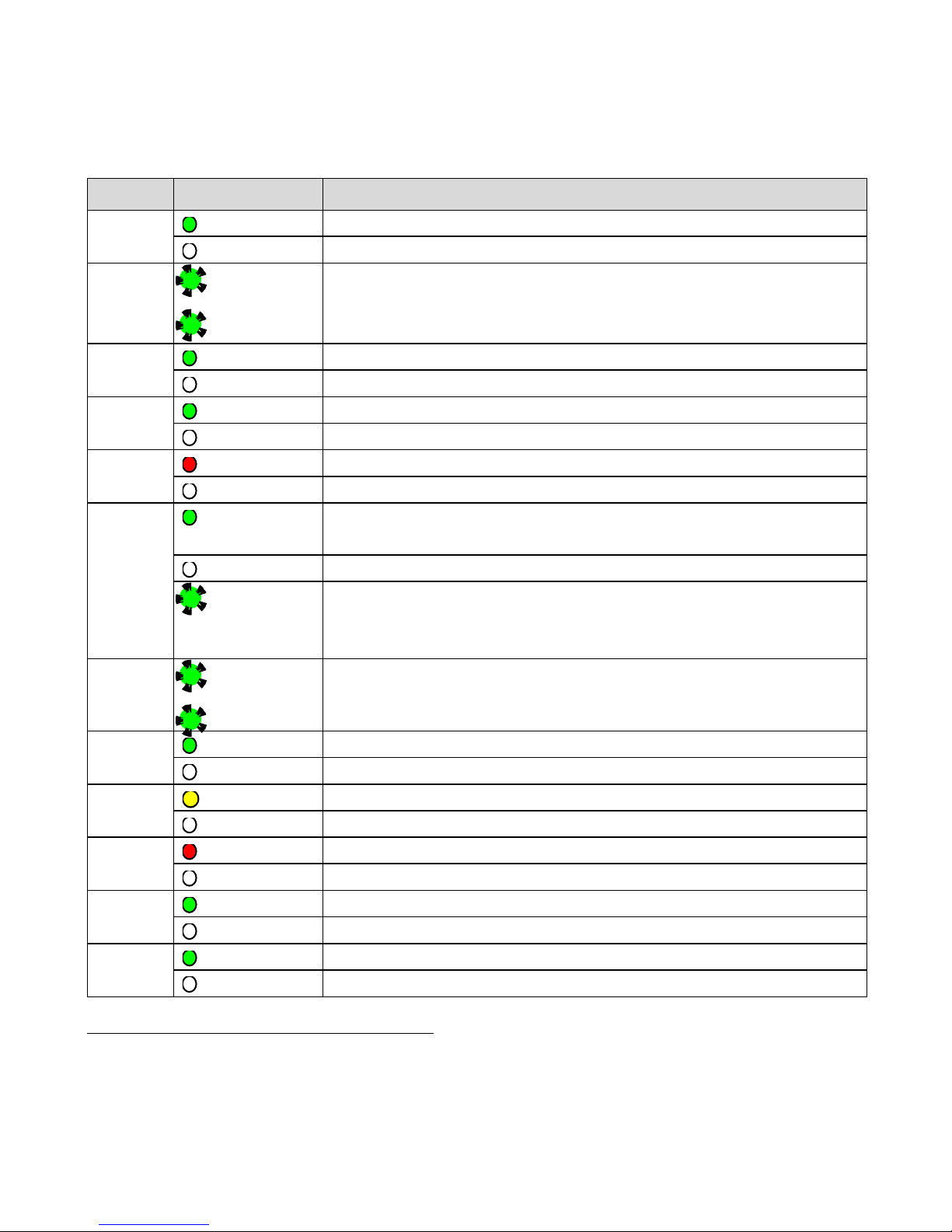
Status Indicators (LEDs)
LED
LED State
Operating State
PLC
MODE1
On Green
PLC is in RUN mode.
Off
PLC is in STOP mode.
RUN
Blinking in
unison
CPU is updating an internal programmable hardware
device.
OE
PHY
PRES
On Green
TPM Physical Presence (not functional).
Off
SSD
On Green
Activity detected on Solid State Disk.
Off
No activity detected on Solid State Disk.
TEMP
On Red
CPU Overtemperature condition detected.
Off
Overtemperature condition not detected.
OK
On Green
CPU has passed its power-up diagnostics and is
functioning properly. (Following initialization sequence.)
Off
Power is not applied or CPU has a problem.
Blinking;
All other
LEDs off
PLC in STOP/Halt state; possible watchdog timer fault.
If the programmer cannot connect, cycle power with
charged Energy Pack attached and refer to fault tables.
OK
Blinking
alternately
CPU encountered a Secure Boot Error.
OE
OE
On Green
Output scan is enabled.
Off
Output scan is disabled.
FRC
On Yellow
One or more Overrides active in I/O Reference Table(s).
Off
No Overrides active in any I/O Reference Table.
FLT
On Red
PLC is in STOP/Faulted mode: a fatal fault has occurred.
Off
No fatal faults detected.
IO
On Green
PROFINET Connection Status = OK.
Off
PROFINET Connection Status not OK.
RACT
On Green
Local Redundant CPU is Ready & Active.
Off
Local Redundant CPU is not Ready.
1
This LED is located between the RUN and STOP pushbuttons. It indicates the PLC Mode.
Page 10
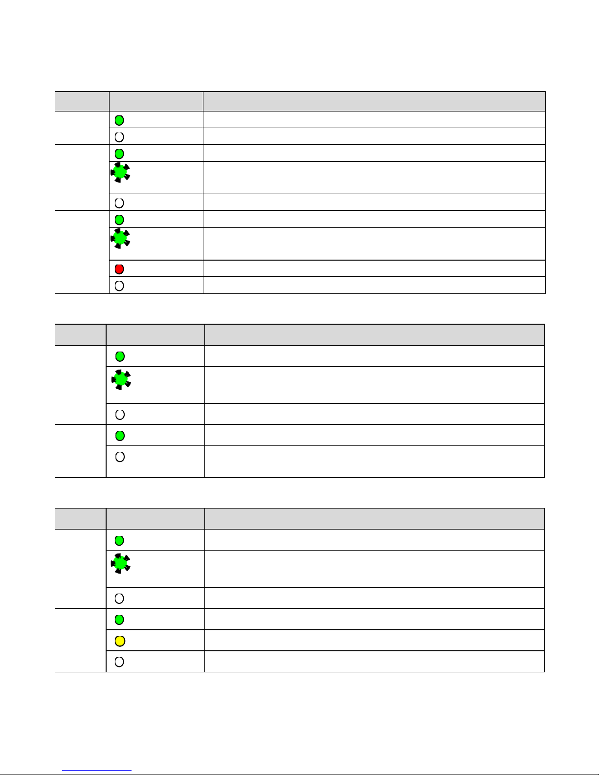
GFK-3002A October 2017 6
LED
LED State
Operating State
RBOK
On Green
Remote Redundant CPU is Ready.
Off
Remote Redundant CPU is not Ready.
FAOK
On Green
Field Agent Running and Connected to Cloud.
Blinking
Green
Blink at 0.5 Hz: Field Agent Starting.
Blink at 1 Hz: Field Agent Running.
Off
Field Agent Off.
PWR
On Green
CPU running.
Blinking
Green
Booting up – diagnostics in progress.
On Red
Off
Off
Reset / Power not detected.
Front Ethernet Indicators (LAN1, LAN2, LAN3 RJ45 Built-in LEDs)
LED
LED State
Operating State
Link
Status
(upper)
On Green
The corresponding link has been established.
Blinking
Green
Traffic is detected at the corresponding port.
Off
No connection established at corresponding port.
Link
Speed
(lower)
On Green
Corresponding data speed is 1 Gbps or 100 Mbps.
Off
Corresponding network data speed is 10 Mbps
Bottom Ethernet Indicators (EFA RJ45 Built-in LED)
LED
LED State
Operating State
Link
Status
(upper)
On Green
The corresponding link has been established.
Blinking
Green
Traffic is detected at the corresponding port.
Off
No connection established at corresponding port.
Link
Speed
(lower)
On Green
Corresponding network data speed is 1 Gbps.
On Yellow
EFA port only: network data speed is 100 Mbps
Off
Corresponding network data speed is 10 Mbps
Page 11

7 IC695CPE400 Rackless CPU w/Field Agent Quick Start Guide GFK-3002A
Front-Panel Ethernet Ports
LAN1 connects to the uppermost RJ45 connector (Figure 1). It is not switched.
LAN2 connects to the middle two RJ45 connectors (Figure 1). These two ports are
switched internally.
LAN3 connects to the two lower RJ45 connectors (Figure 1). These two ports are
switched internally. LAN3 may only be used to supply a high-speed synchronization
link between the Primary and Secondary CPUs in Hot Standby Redundancy. Both
ports are typically used, as described in the PACSystems Hot Standby CPU
Redundancy User Manual, GFK-2308 (revision L or later).
Each of the embedded Ethernet interfaces automatically senses the data rate
(10 Mbps or 100 Mbps or 1 Gbps), communications mode (half-duplex or full-duplex),
and cabling arrangement (straight-through or crossover) of the attached link. LEDs
embedded in each RJ45 connector provide indications per the table above.
LAN1 or LAN2 may be used to communicate with the PME programming software
using the Service Request Transport Protocol (SRTP, a proprietary GE protocol, used
primarily for communication with the programmer).
To establish Ethernet communications between the PME programming and
configuration software and the CPU, you first need to know the target IP address. Use
the OLED menu function to check the IP Address. The factory-shipped default settings
are:
CPE400 LAN1
CPE400 LAN2
CPE400 LAN3
IP Address:
192.168.0.100
10.10.0.100
N/A
Subnet Mask:
255.255.255.0
255.255.255.0
N/A
Gateway:
0.0.0.0
0.0.0.0
N/A
Page 12

GFK-3002A October 2017 8
Serial COM Port
The RJ45 port marked COM is located on
the underside of the CPE400, as shown
in Figure 2. This port is not currently
supported.
Video Display Port
The Display Port is located on the
underside of the CPE400, as shown in
Figure 2. It provides signals for
connecting either a suitable monitor or
video adapter to the unit. This port is
not currently supported.
Figure 2: Underside Ports & Connectors2
Field Agent Port
The RJ45 port marked EFA is located on the underside of the CPE400, as shown in
Figure 2. This is an Ethernet port pre-configured to connect securely to the Predix
cloud environment. For additional information concerning use of this port, refer to the
PACSystems RX7i, RX3i and RSTi-EP CPU Reference Manual, GFK-2222Y or later. For
more detailed information regarding Field Agent, refer to the Field Agent User’s Guide,
GFK-2993.
The FAOK LED, located on the front panel, indicates the status (page 6) of the Field
Agent interface.
2
Only the 24Vdc In Connector is shipped with the CPE400.
Page 13

9 IC695CPE400 Rackless CPU w/Field Agent Quick Start Guide GFK-3002A
Energy Pack Connector
The CPE400 compatible Energy Pack, IC695ACC403, is supplied with a purpose-built
cable, IC695CBL003, which installs in the 24Vdc In and Energy Pack Control & Status
connectors shown in Figure 2. Use of the Energy Pack is optional. When used, it
allows the CPE400 to save its current state upon loss of power. Refer to the
PACSystems RX3i Rackless Energy Pack IC695ACC403 Quick Start Guide, GFK-3000, for
complete wiring and grounding instructions.
Input Power Connector
If no Energy Pack is to be connected, refer to Section 2.4. Otherwise, refer to the
PACSystems RX3i Rackless Energy Pack IC695ACC403 Quick Start Guide, GFK-3000.
Removable Data Storage Device (RDSD)
The CPE400 is equipped with a micro-SD card slot and two USB ports (Figure 1). These
are not currently supported.
Page 14

GFK-3002A October 2017 10
Hardware Installation
Initial Checks
Upon receiving your equipment, carefully inspect all shipping containers for damage.
If any part of the system is damaged, notify the carrier immediately. The damaged
shipping container should be saved as evidence for inspection by the carrier.
As the consignee, it is your responsibility to register a claim with the carrier for
damage incurred during shipment. GE will fully cooperate with you, however, should
such action be necessary.
After unpacking the equipment, record all serial numbers. Serial numbers are
required if you should need to contact Customer Care during the warranty period. All
shipping containers and all packing material should be saved should it be necessary
to transport or ship any part of the system.
Verify that all components of the system have been received and that they agree
with your order. If the system received does not agree with your order, contact
Customer Care.
Installation
As shipped, the CPE400 is intended for mounting on a DIN rail. A panel-mount
adaptor is also available. If panel-mounting is required, replace the DIN-rail adaptor
with the panel-mount adaptor using the screws supplied with that adaptor. Both
adaptors attach to the rear of the CPE400 chassis using four Torx M3 screws. Torque
newly-installed screws to 5.3 in-Ibs (0.6 Nm) if installing a new adaptor plate.
For installation to standards, refer to the Installation and Maintenance Requirements
document, GFK-3004.
Note the thermal requirements for mounting the equipment (Figure 3).
Mount on the DIN rail per Figure 4. (1) Incline the unit so that the upper hooks of the
DIN rail adaptor engage with the upper edge of the DIN rail. (2) Press on the lower
part of the unit until you hear a click. The click indicates that the lower hooks of the
DIN rail adaptor have engaged with the lower edge of the DIN rail.
Dismount from the DIN rail per Figure 5. (1) Grasp the unit securely. (2) Press down on
the release bar as indicated. (3) Swivel the unit away from the DIN rail, then remove.
Page 15

11 IC695CPE400 Rackless CPU w/Field Agent Quick Start Guide GFK-3002A
50mm 50mm
100
mm
100
mm
Air flow
adjacent device right
adjacent device left
adjacent device below
adjacent device above
25mm
Air flow
max. 70°C
Figure 3: Thermal Requirements
Figure 4: Mounting on DIN Rail
Figure 5: Dismounting from DIN Rail
Page 16

GFK-3002A October 2017 12
If using the panel-mount adaptor, two options are available: mount using two screws
(Figure 6) or, for more secure mounting, mount using four screws (Figure 7).
Figure 6: 2-screw panel mount
Figure 7: 4-screw panel mount
Installation in Hazardous Areas
Refer to the Installation and Maintenance Requirements document, GFK-3004.
Page 17

13 IC695CPE400 Rackless CPU w/Field Agent Quick Start Guide GFK-3002A
Connect to Power Supply
The 24Vdc power input connector is located on
the underside of the CPE400, as shown in Figure 8.
The signal pinouts are also indicated.
The mating connector for the CPE400 24Vdc
power input is the 3-pin Phoenix 1827716 shown
in Figure 9. The power supply cable prepared by
the user must use the specified mating connector.
The positive “+” and negative “-“ signals are
required. FGND is optional, but recommended.
For the mating connector, the compatible
conductor size is from 24AWG to 16AWG. Strip the
wires back 7mm before inserting into the
connector. Tightening torque for the three signal
screws is 2.2 in-Ibs (0.248Nm). Secure the mating
connector to the power input connector via the
two captive screws provided.
The user-supplied SELV3 power supply must
supply voltage in the range of 18Vdc to 30Vdc.
Once the power supply cable (or compatible
Energy Pack ACC403) has been attached to the
CPE400 and the power supply has been turned on,
the unit will start booting. There is no need to push
any button.
The unit is equipped with built-in reverse polarity
protection. If + and - are swapped the unit will not
power-up. If + is connected to FGND, this will
cause a short. The power supply needs to protect
itself against this condition.
Figure 8: 24Vdc Power Input
Connector
Figure 9: 24Vdc Power Input
Mating Connector
Inrush Current
The CPE400 may experience an inrush current of up to 49A for 15µs.
3
SELV = Safety Extra Low Voltage
Page 18

GFK-3002A October 2017 14
Overvoltage protection
In the CPE400, the voltage to the inner loads is clamped to 33Vdc. At 33Vdc, the
internal clamping diode starts conducting at 1mA. Any further increase in the voltage
will cause the internal current fuse to blow and/or the clamping diode to break.
• CAUTION – EQUIPMENT REPAIR REQUIRED – Internal components must be
repaired at the factory; they are not field replaceable. Contact the GE
support team at https://ge-ip.force.com/communities/CC_Contact
Overcurrent protection
The function protects the internal circuitry from overcurrent conditions before serious
damage can occur, such as overheating of the equipment. The fuse is rated for 4A
continuous current. Once the sensed current reaches 40A, the fuse will blow after a
period of 10ms to 100ms.
• CAUTION – EQUIPMENT REPAIR REQUIRED – Internal components must be
repaired at the factory; they are not field replaceable. Contact the GE
support team at https://ge-ip.force.com/communities/CC_Contact
Grounding
Grounding via the FGND connection on the 3-pin 24Vdc In power header is
recommended (see section 2.4), but is not required if the CPE400 is mounted to a
grounded metal panel. Furthermore, if an Energy Pack is connected, be sure to
comply with grounding procedures as described in PACSystems RX3i Rackless Energy
Pack IC695ACC403 Quick Start Guide, GFK-3000.
Page 19

15 IC695CPE400 Rackless CPU w/Field Agent Quick Start Guide GFK-3002A
Module Start-up
You Will Need:
• This PACSystems Rackless RX3i CPU.
• A compatible SELV 24Vdc, 48W power supply (72W if Energy Pack attached).
• (Optionally) A compatible Energy Pack, IC695ACC403, and corresponding cable.
• If no Energy Pack is to be attached, use the power supply cable described in
Section 2.4.
• A DIN rail, typically mounted in an enclosure, as discussed above. Alternately,
mount the unit using the compatible panel-mount adaptor.
• A computer running Proficy Machine Edition (PME) configuration and
programming software. PME Version 9.00 SIM 8 or later supports the CPE400.
Version 9.50 SIM 5 is required for Hot Standby Redundancy.
• Ethernet cable for connecting the PME programmer computer to the CPE400.
• Additional cables, as needed, to connect each port employed in the application.
• A very small slotted screwdriver to secure the 24Vdc mating connector.
• A T8 Torx screwdriver, if the micro-SD slot cover is to be removed. Note that the
cover must be replaced to achieve immunity from electrical noise.
• A T10 Torx screwdriver, if exchanging the mounting adaptors.
Page 20

GFK-3002A October 2017 16
Basic Start-up Steps:
For startup and configuration of the CPE400, complete the following steps. For full
details on CPE400 operation, refer to the PACSystems RX3i and RX7i CPU Reference
Manual, GFK-2222Y or later.
1. Mount the CPE400, as described in Section 2.2 and per the Installation and
Maintenance Requirements document, GFK-3004.
2. Attach the user-supplied power supply cable as described in Section 2.4 if no
Energy Pack is being used.
3. (optionally) Mount and attach the compatible Energy Pack, IC695ACC403, as
described in the PACSystems RX3i Rackless Energy Pack IC695ACC403 Quick Start
Guide, GFK-3000.
4. Turn on the power supply unit: the unit should then run without the need to press
any buttons.
5. If not previously configured, configure the RX3i PLC using PME 9.00 SIM 8 or later,
as described in the Configuration section below.
Note: When the ACC403 Energy Pack is powered up, a finite period is required to
charge it up to its operating level. During this time, the Energy Pack will
indicate this condition via its LEDs (refer to the PACSystems RX3i Rackless
Energy Pack IC695ACC403 Quick Start Guide, GFK-3000).
The CPE400 will begin its boot cycle immediately upon power application.
However, the embedded controller will not start its control until the ACC403 is
charged. This typically takes 45 seconds or less. In the event the ACC403 is
faulty or is not communicating, CPE400 commences operation without the
Energy Pack.
Note: In the event of loss of power, with the ACC403 Energy Pack connected and
charged up, the CPE400 remains on for 4 seconds to backup user memory
into its non-volatile memory.
Page 21

17 IC695CPE400 Rackless CPU w/Field Agent Quick Start Guide GFK-3002A
Configuration
To configure, the CPE400, connect the computer running the PME programming
software to any of the front-panel Ethernet ports. PME 9.00 SIM 8 or later is required
The CPE400 is the first controller available in the PACSystems RX3i Rackless family.
Configuration will either start out using the RX3i Rackless CPE400 template when
creating a new project, or will convert an existing project to the CPE400 using the
Family Conversion feature in PME.
Backwards Compatibility
To convert an existing project which uses any other PLC, use the Family Conversion
feature in PME. Be aware of the constraints involved, as will be notified in PME. For
instance, the first PROFINET Controller in an RX3i CPU320 application will be assigned
to the embedded PROFINET Controller feature of the CPE400.
PROFINET Controller Configuration
An Embedded PROFINET Controller may be configured on LAN2. To enable the
PROFINET Controller in a CPE400 project, select the CPE400 target in the PME
Navigator (Figure 10) and open the Hardware Configuration. On the Settings tab,
change the designated LAN Mode of the selected port to PROFINET. The PROFINET
Controller node description then displays that a PROFINET node exists on the selected
LAN (under the CPE400). For further details, refer to the PACSystems RX3i PROFINET IO
Controller User Manual, GFK-2571.
Figure 10: PME Navigator showing PROFINET node on LAN2
Page 22

GFK-3002A October 2017 18
Field Agent Configuration
4.3.1. Start the Embedded Field Agent (EFA)
After providing the CPE400 with power, the Embedded Field Agent (EFA) application
will begin to boot. The FAOK LED will start blinking to indicate when the EFA has
booted and is ready for user logins. (This may take about two minutes.)
4.3.2. Log into the Web Console
To log into the Web Console:
1. Connect a computer to the EFA’s IICS Cloud Port or EFA Port.
2. Configure the computer’s network adapter to be an address on the Field Agent
network.
• The EFA’s default IICS Cloud Port or EFA Port is assigned 172.31.0.100
with subnet mask 255.255.0.0. Set your computer’s network adapter to
any other IP address on the 172.31.x.x network. For example,
172.31.0.101 with subnet mask 255.255.0.0.
3. Use the OLED Menu to enable Configuration Mode as follows:
• From the Main Menu, select the “FA Settings” menu item.
• From the FA Settings Menus, select the “Commands” menu item.
• From the Commands Menus, select the “Config Mode” menu item.
• Confirm entering Config Mode.
• Configuration Mode will remain active for one hour or until the above
steps are repeated to disable Configuration Mode.
Note: Browsing to the Web Console too soon may result in seeing an
Authentication Required or similar drop-down/pop-up dialog. Entering a
user name and password into this dialog will not permit a log-in to the Web
Console. Wait for the Field Agent to fully boot as indicated by the FAOK LED
and re-attempt to browse to the Web Console. Closing the current browser
tab or window may also be required.
4. Using Google Chrome (recommended), browse to the Field Agent’s Web Console
at https://172.31.0.100:8443/system/console.
5. Since the Web Console uses a self-signed certificate, the browser will warn that
the connection is not private. When prompted, accept the connection.
Page 23

19 IC695CPE400 Rackless CPU w/Field Agent Quick Start Guide GFK-3002A
6. Login using the default credentials.
• Default User Name: predix
• Default Password: predix2machine
7. A prompt to change the default password displays. Complete the form to
change the default password.
8. The password complexity requirements display if the chosen password is not
sufficiently complex. After changing the password, log in using the new
password.
Page 24

GFK-3002A October 2017 20
9. Verify that the Log Service page displays, which indicates a successful login.
Note: After some idle time, the Web Console will time out. If this occurs, the user
will need to return to the main page to log back into the console. Session
timeout does not automatically redirect the console back to the login
page.
4.3.3. Configure the Network
4.3.3.1. EFA IP Addresses
By default, the Embedded Field Agent’s WAN interface is set to a static address of
172.31.0.100 with a subnet mask of 255.255.0.0.
To change the WAN IP address
1. Verify that the WAN Ethernet cable is connected to the IICS Cloud port / EFA Port.
If a network proxy is needed to connect the field agent to the WAN, refer to the
section Configure a Network Proxy.
2. From the Web Console, navigate to the Technician Console, Network
Configuration page.
Page 25

21 IC695CPE400 Rackless CPU w/Field Agent Quick Start Guide GFK-3002A
3. Set the WAN interface settings appropriately for the Field Agent’s network. DHCP
can be used for networks where a DHCP server is available, and a static IP
address for networks where each device is manually assigned an address. Click
the Save button to accept the changes.
Note: The DNS servers can also be configured to be obtained automatically or
specified statically. When using a static IP address, DNS servers must also
be specified statically.
4.3.3.2. Configure a Network Proxy
A Network Proxy is only required when your network architecture is configured to
restrict access directly to the Internet. Contact your network administrator for the
Network Proxy information.
If a network HTTP/HTTPS proxy server is used to route traffic from the intranet to the
Internet, the network proxy must be configured in the Web Console under Technician
Console, Network Configuration. To add or update a network proxy server, check the
Page 26

GFK-3002A October 2017 22
“Enable HTTP/HTTPS Proxy” check box, enter the proxy server’s address and port in
the form “proxy:port” into the Proxy Settings text box, and press the Save button.
To verify the Field Agent can successfully use the newly configured network proxy to
reach the Internet, use the Test Connection feature of the Field Agent Updater page
in the Web Console under Technician Console, Field Agent Updater. Internet
reachability can be tested by using either the default Update URL or any other
desired URL and pressing the Test Connection button.
If the URL is reachable, a Test Connection Succeeded message is displayed below the
Test Connection button after the button is pressed. Otherwise, a message will appear
indicating that the Test Connection attempt failed.
4.3.3.3. Configure Time Synchronization
In order for industrial data time-stamping and Field Agent diagnostic information to
operate reliably, it is important for the Field Agent to have an accurate time source.
The Field Agent has two methods of synchronizing time – either by using a Network
Time Protocol (NTP) server or by pulling time from a web page hosted by an HTTPS
web server with its own reliable time source. Either method can be configured in the
Web Console under Technician Console, Time Sync Configuration.
Page 27

23 IC695CPE400 Rackless CPU w/Field Agent Quick Start Guide GFK-3002A
4.3.3.3.1. Using NTP Time Synchronization
By default, time synchronization is configured to use the time.windows.com NTP
Server. If a valid network path to the Internet exists, time will be synchronized when
the Field Agent boots and continuously while running. The current date and time on
the Field Agent is displayed above the Save button on the Time Sync Configuration
page when the page loads, and can be updated by pressing the Save button or
reloading the page.
To change the NTP server to use for time synchronization enter the new NTP server
URL in the NTP Server textbox and press the Save button. If the new server was
successfully configured, a success statement will be displayed and the updated time
will be displayed. If the time and date was more than 20 minutes out of date prior to
time synchronization occurring after pressing the Save button, the Web Console
session may end and an error message may be presented indicating that the
session’s timeout had been reached. Log back into the Web Console to verify the time
was updated as expected.
4.3.3.3.2. Using HTTPS Time Synchronization
Time synchronization can also be configured to use an HTTPS web server's time by
pulling it from the header of the web page it serves. To configure HTTPS time
synchronization, select the HTTPS Server radio button on the Time Sync Configuration
page, enter a valid HTTPS URL, and press the Save button. If a network proxy is in use,
this time synchronization method will only work with HTTPS URLs that do not require
a network proxy in order to reach them.
Page 28

GFK-3002A October 2017 24
If the new HTTPS URL was successfully configured after pressing the Save button, a
success statement will be displayed and the updated time will be displayed. If the
time and date was more than 20 minutes out of date prior to time synchronization
occurring after pressing the Save button, the Web Console session may end and an
error message may be presented indicating that the session’s timeout had been
reached. Log back into the Web Console to verify the time was updated as expected.
Redundancy Configuration
With firmware version 9.30 or later, it is possible to configure the CPE400 as a Hot
Standby Redundancy CPU with PROFINET IO. The two ports on LAN3 are used
exclusively for this purpose: they provide a high-speed data synchronization link
between the two CPUs. Connect the upper LAN3 port of the Primary CPU to the upper
LAN3 port of the Secondary CPU and connect the lower LAN3 port of the Primary to
the lower LAN3 port of the Secondary. Note that no additional hardware, other than
the two redundant CPUs, may be connected to LAN3.
To enable redundancy in a CPE400 project, select the CPE400 target in the PME
Navigator and use the Property Inspector to change the Enable Redundancy target
property to True.
Important: Set the Background Window Timer to a minimum of 5ms in both the
Primary and Backup CPE400 hardware configurations. The Background Window
Timer setting may be found on the Scan Tab in the CPE400’s hardware configuration.
Once configured for HSB Redundancy, the RACT and RBOK LEDs (Figure 1) become
functional. RACT indicates the Local CPU is Ready & Active; RBOK indicates the
Remote CPU is Ready. These two LEDs are also reflected in the Status Data of the CPU
and are presented as OPC UA Variables.
The OLED display includes two menu items used in conjunction with Redundancy:
• RDN Info provides status information via the OLED display.
• RDN Command permits the operator to perform a Role Switch.
For further details, refer to the PACSystems Hot Standby CPU Redundancy User
Manual, GFK-2308 (rev L or later).
Page 29

25 IC695CPE400 Rackless CPU w/Field Agent Quick Start Guide GFK-3002A
Additional Information
Proficy Logic Developer-PLC Getting Started
GFK-1918
PACSystems RX7i, RX3i and RSTi-EP CPU Reference Manual
GFK-2222
PACSystems RX7i, RX3i and RSTi-EP TCP/IP Ethernet Communications User’s
Manual
GFK-2224
PACSystems TCP/IP Ethernet Communications Station Manager Manual
GFK-2225
PACSystems Hot Standby CPU Redundancy User Manual
GFK-2308
PACSystems RX3i System Manual
GFK-2314
PACSystems RXi, RX7i, RX3i and RSTi-EP Controller Secure Deployment Guide
GFK-2830
PACSystems RX7i, RX3i and RSTi-EP CPU Programmer’s Reference Manual
GFK-2950
PACSystems HART Pass Through User Manual
GFK-2929
PACSystems RX3i PROFINET IO Controller User Manual
GFK-2571
PROFINET I/O Devices Secure Deployment Guide
GFK-2904
PACSystems RX3i Rackless Energy Pack IC695ACC403 Quick Start Guide
GFK-3000
IC695CPE400 RX3i 1.2GHz 64MB Rackless CPU w/Field Agent
Important Product Information
GFK-3003
IC695CPE400 RX3i 1.2GHz 64MB Rackless CPU w/Field Agent
Installation and Maintenance Requirements
GFK-3004
Field Agent User’s Guide
GFK-2993
User manuals, product updates and other information sources are available on the
Support website, www.geautomation.com under Controllers and IO, RX3i Controllers.
Page 30

GFK-3002A October 2017 26
For binaries that you receive in this distribution that are licensed under any version of the GNU
General Public License (GPL) or the GNU Library/Lesser General Public License (LGPL), you can
receive, for a fee of no more than our cost of physically performing the distribution, a complete
machine-readable copy of the source code by sending a written request to:
Automation & Controls
GE
Attn: General Counsel
2500 Austin Drive
Charlottesville, VA 22911
Your request should include: (i) the name of the covered binary, (ii) the version number of the
product containing the covered binary, (iii) your name, (iv) your company name (if applicable)
and (v) your return mailing and email address.
This offer is valid for three (3) years after the date of the last distribution of this particular version
of this product. For any code in this product covered by version 3 of the GNU General Public
License (GPL), then this offer is valid for those who possess the object code for either i) for the
aforementioned three (3) years, or ii) until the date on which we cease offering both spare parts
and customer support for this particular version of this product, whichever occurs last.
https://digitalsupport.ge.com/communities/en_US/Documentation/PACSystemsIC695CPE400-Open-Source-Software-information
Page 31

GE
Contact Information
Americas: 1-800-433-2682 or 1-434-978-5100
Global regional phone numbers are available on our web site
www.geautomation.com
Copyright © 2016-2017 General Electric Company.
All Rights Reserved.
* Trademark of General Electric Company and/or its subsidiaries.
All other trademarks are property of their respective holders
GFK-3002A
g
 Loading...