

GE PACSystems RX3i, PACSystems RSTi-EP, IC695PNC001, IC695CPE400, EPSCPE100 User Manual
...Page 1

For Public Disclosure
GE
Automation & Controls
Programmable Control Products
RX3i & RSTi-EP PROFINET IO-Controller User Manual GFK-2571N
PACSystems*
RX3i & RSTi-EP
PROFINET IO-Controller
User Manual
GFK-2571N
May 2018
Page 2

Legal Information
For Public Disclosure
Warnings, Cautions, and Notes as Used in this Publication GFL-002
Warning
Warning notices are used in this publication to emphasize that hazardous
voltages, currents, temperatures, or other conditions that could cause
personal injury exist in this equipment or may be associated with its use.
In situations where inattention could cause either personal injury or
damage to equipment, a Warning notice is used.
Caution
Caution notices are used where equipment might be damaged if care is
not taken.
Note: Notes merely call attention to information that is especially significant to understanding and
operating the equipment.
These instructions do not purport to cover all details or variations in equipment, nor to provide for
every possible contingency to be met during installation, operation, and maintenance. The
information is supplied for informational purposes only, and GE makes no warranty as to the
accuracy of the information included herein. Changes, modifications, and/or improvements to
equipment and specifications are made periodically and these changes may or may not be reflected
herein. It is understood that GE may make changes, modifications, or improvements to the
equipment referenced herein or to the document itself at any time. This document is intended for
trained personnel familiar with the GE products referenced herein.
GE may have patents or pending patent applications covering subject matter in this document. The
furnishing of this document does not provide any license whatsoever to any of these patents.
GE PROVIDES THE FOLLOWING DOCUMENT AND THE INFORMATION INCLUDED THEREIN AS-IS AND
WITHOUT WARRANTY OF ANY KIND, EXPRESSED OR IMPLIED, INCLUDING BUT NOT LIMITED TO ANY
IMPLIED STATUTORY WARRANTY OF MERCHANTABILITY OR FITNESS FOR PARTICULAR PURPOSE.
* indicates a trademark of General Electric Company and/or its subsidiaries.
All other trademarks are the property of their respective owners.
©Copyright 2011-2018 General Electric Company.
All Rights Reserved
Page 3

Contact Information
If you purchased this product through an Authorized Channel Partner, please contact the seller directly.
General Contact Information
Online technical support and GlobalCare
www.geautomation.com/support
Additional information
www.geautomation.com
Solution Provider
solutionprovider.ip@ge.com
Technical Support
If you have technical problems that cannot be resolved with the information in this manual, please contact us
by telephone or email, or on the web at www.geautomation.com/support
Americas
Phone
1-800-433-2682
1-780-420-2010 (if toll free 800-option is unavailable)
Email
digitalsupport@ge.com
Primary language of support
English
Europe, Middle East, & Africa
Phone
+800-1-433-2682
+ 420-296-183-331 (if toll free 800-option is unavailable or
if dialing from a mobile telephone)
Email
digitalsupport.emea@ge.com
Primary languages of support
English, French, German, Italian, Spanish
Asia
Phone
+86-400-820-8208
+86-21-3877-7006 (India, Indonesia & Pakistan)
Email
digitalsupport.apac@ge.com
Primary languages of support
Chinese, English
Page 4

GFK-2571N May 2018 i
Table of Contents
RX3i & RSTi-EP PROFINET IO-Controller User Manual GFK-2571N
Table of Contents ............................................................................................................................................ i
Table of Figures .............................................................................................................................................. vi
Chapter 1 Introduction ......................................................................................................................... 1
1.1 Revisions in this Manual ........................................................................................................... 2
1.2 PROFINET Controller Description ......................................................................................... 4
1.2.1 PNC001 Description ................................................................................................................................................... 4
1.2.2 Embedded PROFINET Controller ........................................................................................................................... 5
1.3 PNC001 Module Specifications ............................................................................................... 6
1.4 Operating Range for Surrounding Air Temperature ......................................................... 9
1.4.1 Operating Temperature De-Rating: ...................................................................................................................... 9
1.5 PNC001 Module Controls and Indicators ........................................................................... 10
1.5.1 PNC001 Hardware Implementions (-Ax & -Bxxx) ........................................................................................ 11
1.5.2 Ethernet Network Ports ......................................................................................................................................... 12
1.5.3 USB Port(s) .................................................................................................................................................................. 13
1.5.4 Reset Pushbutton ..................................................................................................................................................... 13
1.5.5 LEDs on the CPUs with Embedded PROFINET .............................................................................................. 13
1.5.6 LEDs on the PNC001 Module ............................................................................................................................... 13
1.6 PROFINET Networks for PACSystems ............................................................................... 14
1.6.1 Compression ............................................................................................................................................................... 15
1.6.2 Basic System: One RX3i CPU and One PROFINET Controller using a single port ............................ 16
1.6.3 Basic System: One RX3i CPU and One PROFINET Controller using multiple ports ........................ 17
1.6.4 Basic System: Third-Party Devices and PME Programmer ....................................................................... 18
1.6.5 Systems with One RX3i CPU and Two PROFINET Controllers ................................................................ 19
1.6.6 One RX3i CPU with Four Controllers on Separate Networks.................................................................. 21
1.6.7 Two RX3i CPUs with Two PROFINET Networks and One Ethernet Network .................................... 22
1.6.8 Systems that use PROFINET System Redundancy (PNSR) ...................................................................... 23
1.6.9 Systems that use Hot Standby CPU Redundancy ........................................................................................ 24
1.6.10 RSTi-EP Standalone CPU with embedded PROFINET Controller using a single port .................... 25
1.6.11 RSTi-EP Standalone CPU with embedded PROFINET Controller using multiple ports ................. 26
1.6.12 RSTi-EP Standalone CPU with embedded PROFINET Controller using MRP .................................... 27
Page 5

Contents
ii PACSystems* RX3i & RSTi-EP PROFINET IO-Controller User Manual GFK-2571N
1.7 Glossary ..................................................................................................................................... 28
1.8 Documentation ........................................................................................................................ 30
Chapter 2 Installation ......................................................................................................................... 31
2.1 Pre-Installation Check ............................................................................................................ 32
2.2 Installation in Hazardous Areas .......................................................................................... 33
2.2.1 ATEX Marking .............................................................................................................................................................. 33
2.3 Removing the Backplane Knockout .................................................................................... 34
2.4 Module Installation ................................................................................................................. 35
2.5 Module Removal ...................................................................................................................... 35
2.6 Hot Insertion and Removal ................................................................................................... 36
2.7 Ethernet Port Connections ................................................................................................... 37
2.7.1 PROFINET Network Connections ....................................................................................................................... 37
2.7.2 RJ45 Port Connections ........................................................................................................................................... 37
2.7.3 Installing SFP Devices.............................................................................................................................................. 40
2.7.4 Removing SFP Devices ............................................................................................................................................ 42
2.8 PNC001 LED Behavior ............................................................................................................. 43
2.8.1 Power-up LED Patterns .......................................................................................................................................... 43
2.8.2 Detailed LED Descriptions ..................................................................................................................................... 44
2.9 Installing the USB Port Driver .............................................................................................. 46
2.10 Firmware Updates ................................................................................................................... 47
2.10.1 PNC001 Firmware Updates .................................................................................................................................. 47
2.10.2 Firmware Updates for Embedded PROFINET ................................................................................................ 47
2.11 PNC001 Time Synchronization with the Host RX3i CPU ................................................ 48
Chapter 3 Configuration ..................................................................................................................... 49
3.1 Configuration Overview ........................................................................................................ 50
3.1.1 System Planning ........................................................................................................................................................ 50
3.1.2 Basic Configuration Steps ..................................................................................................................................... 51
3.2 Configuration Tools ................................................................................................................ 52
3.2.1 Non-Volatile Configuration Parameters .......................................................................................................... 52
3.3 Configuring an RX3i PROFINET Controller ........................................................................ 53
3.3.1 Configuring a Rack-Mounted RX3i PROFINET Controller (PNC001) ..................................................... 53
3.3.2 Configuring an Embedded RX3i PROFINET Controller ............................................................................... 53
3.3.3 Configuring an Embedded RSTi-EP PROFINET Controller ........................................................................ 54
Page 6

Contents
GFK-2571N May 2018 iii
3.4 Configuring PROFINET System Redundancy..................................................................... 55
3.5 Exploring PROFINET Networks ............................................................................................ 56
3.5.1 Configuring a PROFINET Controller on a LAN................................................................................................ 57
3.5.2 Configuring PROFINET Controller Parameters ............................................................................................. 58
3.6 Configuring PROFINET LANs ................................................................................................. 62
3.6.1 Configuring the LAN Properties .......................................................................................................................... 63
3.7 Adding a VersaMax PROFINET Scanner to a LAN............................................................. 65
3.7.1 Configuring VersaMax PROFINET Scanner Parameters ............................................................................ 66
3.7.2 Adding VersaMax PROFINET Scanner Power Supplies .............................................................................. 70
3.7.3 Adding VersaMax Modules to a Remote Node ............................................................................................. 71
3.7.4 Installing Power Supplies Between Modules ................................................................................................. 72
3.7.5 Configuring VersaMax Module Parameters ................................................................................................... 73
3.8 Adding a Third-Party IO-Device to a LAN .......................................................................... 75
3.8.1 Editing Third-Party IO-Device Parameters ..................................................................................................... 76
3.8.2 Configuring Sub-Modules of a Third-Party IO-Device ................................................................................ 78
3.9 Viewing / Editing IO-Device Properties .............................................................................. 79
3.10 Assigning IO-Device Names................................................................................................... 81
3.11 After the Configuration is Stored to the RX3i CPU ......................................................... 83
Chapter 4 PROFINET System Operation ......................................................................................... 85
4.1 PROFINET Operation Overview ........................................................................................... 86
4.1.1 PROFINET Communications ................................................................................................................................. 87
4.2 Operations of the PROFINET Controller in the PACSystems System ........................ 90
4.2.1 Duplicate PROFINET IO-Device IP Address .................................................................................................... 90
4.2.2 Duplicate PROFINET IO-Controller IP Address ............................................................................................. 91
4.2.3 Resolving Duplicate IP Addresses ...................................................................................................................... 91
4.3 I/O Scanning .............................................................................................................................. 92
4.4 Data Coherency ........................................................................................................................ 93
4.5 Performance Factors .............................................................................................................. 94
4.6 PROFINET IO Update Rate Configuration .......................................................................... 95
4.7 PACSystems CPU Operations for PROFINET .................................................................... 96
4.7.1 Reference ID Variables for the PACSystems Application ......................................................................... 96
4.7.2 PNIO_DEV_COMM Function Block ..................................................................................................................... 97
4.7.3 Reset Smart Module for the PROFINET Controller ...................................................................................... 98
4.7.4 DO I/O for Remote IO Modules ............................................................................................................................ 98
4.7.5 Scan Set I/O for Remote I/O Modules ............................................................................................................... 99
4.7.6 PACSystems CPU Defaults - Inputs ................................................................................................................... 99
Page 7

Contents
iv PACSystems* RX3i & RSTi-EP PROFINET IO-Controller User Manual GFK-2571N
4.7.7 PACSystems CPU Defaults - Outputs ............................................................................................................... 99
Chapter 5 Diagnostics ....................................................................................................................... 101
5.1 Power-up and Reset (PNC001 Module) ............................................................................ 102
5.1.1 Module Restart ....................................................................................................................................................... 102
5.1.2 Problems During Power-up and Reset .......................................................................................................... 103
5.1.3 Transitioning to Firmware Update Mode ..................................................................................................... 103
5.2 Special LED Blink Patterns .................................................................................................. 104
5.2.1 Special LED Pattern - Module Identification ............................................................................................... 104
5.2.2 Special LED Pattern - Microprocessor Overtemperature ...................................................................... 104
5.2.3 Firmware Update ................................................................................................................................................... 104
5.2.4 Internal Update ....................................................................................................................................................... 104
5.3 Status Reporting ................................................................................................................... 105
5.4 I/O Fault Contacts ................................................................................................................. 106
5.5 Fault Locating References ................................................................................................... 107
5.6 Fatal Error Reporting ............................................................................................................ 108
5.7 PROFINET IO Alarms ............................................................................................................. 109
5.8 Local Log Table of the PROFINET Controller .................................................................. 110
5.8.1 Faults Unique to Local Log Table ..................................................................................................................... 111
5.8.2 Viewing and Clearing the Local Log Table .................................................................................................... 113
5.9 PROFINET Controller Faults in the PACSystems Fault Tables ................................... 116
5.9.1 Clearing the PACSystems Fault Tables ......................................................................................................... 116
5.9.2 Faults Reported to the PACSystems Controller Fault Table ................................................................ 116
5.9.3 Faults Reported to the PACSystems I/O Fault Table ............................................................................... 118
Chapter 6 Redundant Media ............................................................................................................ 127
6.1 PROFINET Media Redundancy Protocol ........................................................................... 128
6.1.1 MRP Failover Performance ................................................................................................................................. 129
6.1.2 Bumpless Operation with MRP ........................................................................................................................ 130
6.1.3 MRP Operation for I/O Update Rates of 16ms or Greater ..................................................................... 131
6.1.4 MRP Operation at I/O Update Rates Less Than 16ms ............................................................................ 131
6.1.5 Minimum I/O Rate When Configured in an MRP Ring ............................................................................. 131
6.1.6 Minimum I/O Update Rates for Bumpless Operation in an MRP Ring Topology .......................... 132
6.1.7 MRP Ring Ethernet Traffic Storm Prevention ............................................................................................. 133
6.1.8 Third-party MRP Manager Use with PROFINET Controller as MRP Client ....................................... 134
Page 8

Contents
GFK-2571N May 2018 v
6.2 Ring Topology with One Controller .................................................................................. 135
6.3 Ring Topology with Multiple Controllers ........................................................................ 136
6.4 Setting Up Media Redundancy Protocol ......................................................................... 137
6.4.1 Media Redundancy Setup for a PROFINET Controller ............................................................................. 137
6.5 Sequence for Enabling Media Redundancy ..................................................................... 138
6.6 Sequence for Replacing a Media Redundancy Manager .............................................. 139
6.7 Procedure for Disabling Media Redundancy .................................................................. 140
Chapter 7 Network Management .................................................................................................. 141
7.1 SNMP ........................................................................................................................................ 142
7.1.1 Overview of SNMP ................................................................................................................................................. 142
7.1.2 Supported SNMP Features ................................................................................................................................. 143
7.1.3 SNMP Read Access ................................................................................................................................................ 143
7.1.4 SNMP Write Access .............................................................................................................................................. 143
7.1.5 MIB-II Groups Supported .................................................................................................................................... 144
7.1.6 MIB-II System Group Values .............................................................................................................................. 145
7.2 LLDP ......................................................................................................................................... 146
7.2.1 Overview of LLDP ................................................................................................................................................... 146
7.2.2 LLDP Operation ...................................................................................................................................................... 146
7.2.3 LLDP TLVs.................................................................................................................................................................. 147
Appendix A PROFINET IO Performance Examples ............................................................................ 151
A-1 Systems with RX3i PNS .................................................................................................................... 152
A-1.1 RX3i System Performance Summary ............................................................................................................. 152
A-1.2 RX3i System Descriptions .................................................................................................................................. 152
A-2 Systems with VersaMax PNS .......................................................................................................... 153
A-2.1 VersaMax System Performance Summary .................................................................................................. 153
A-2.2 VersaMax System Descriptions ....................................................................................................................... 154
A-3 Systems with RSTi-EP EPSCPE100/CPE115 ................................................................................. 156
A-3.1 RSTi-EP CPE100/CPE115 Embedded PROFINET Controller System Performance Summary . 156
A-3.2 RSTi-EP System Descriptions ............................................................................................................................ 157
Page 9

Contents
vi PACSystems* RX3i & RSTi-EP PROFINET IO-Controller User Manual GFK-2571N
Table of Figures
Figure 1: IC695PNC001-Bxxx Front View ___________________________________________________________ 4
Figure 2: IC695PNC001-Ax Controls & Indicators ____________________________________________________ 10
Figure 3: IC695PNC001-Bxxx Controls & Indicators __________________________________________________ 10
Figure 4: PNC001 Ethernet Ports Location and Type _________________________________________________ 12
Figure 5: CPE100/CPE115 Ethernet Ports Location and Type __________________________________________ 12
Figure 6: RX3i System with one PROFINET Controller and one PROFINET LAN _____________________________ 16
Figure 7: RX3i System with one PROFINET Controller and multiple PROFINET LANs ________________________ 17
Figure 8: RX3i System interfacing with Third-Party Devices and with PME Programmer ____________________ 18
Figure 9: RX3i System with two PNC001 Modules and one Daisy-Chain PROFINET LAN _____________________ 19
Figure 10: RX3i System with two PNC001 modules and two Daisy-Chain PROFINET LANs ___________________ 20
Figure 11: RX3i System with four PNC001 modules and four Daisy-Chain PROFINET LANs ___________________ 21
Figure 12: RX3i System with two PROFINET LANs & one Ethernet LAN __________________________________ 22
Figure 13: PROFINET System Redundancy S2 _______________________________________________________ 23
Figure 14: RX3i Hot Standby CPU Redundancy Network with MRP Ring Topology _________________________ 24
Figure 15: RSTi-EP System with embedded PROFINET Controller and one PROFINET LAN ____________________ 25
Figure 16: RX3i System with one PROFINET Controller and multiple PROFINET LANs _______________________ 26
Figure 17: RX3i System with one PROFINET Controller and PROFINET IO Network MRP _____________________ 27
Figure 18: RX3i Backplane showing Removable Plastic Knockout _______________________________________ 34
Figure 19: Install Module into RX3i Backplane ______________________________________________________ 35
Figure 20: Remove Module from RX3i Backplane ___________________________________________________ 35
Figure 21: Ethernet Ports on PNC001 Module ______________________________________________________ 37
Figure 22: Interconnect using Copper Cables / RJ45 Connectors ________________________________________ 38
Figure 23: Interconnect using Multi-Mode Fiber ____________________________________________________ 38
Figure 24: Interconnect using Single-Mode Fiber ____________________________________________________ 38
Figure 25: CAT5e/CAT6 (shielded or unshielded) with RJ 45 Connector __________________________________ 39
Figure 26: Multi-Mode Fiber with LC connector _____________________________________________________ 39
Figure 27: Single-Mode Fiber with LC connector ____________________________________________________ 39
Figure 28: Method for Attaching SFP Device Connector to PNC001 Port _________________________________ 40
Figure 29: Fiber SFP showing LC Connector ________________________________________________________ 42
Figure 30: Copper SFP showing RJ45 Connector ____________________________________________________ 42
Figure 31: PNC001-Bxxx Front View showing LEDs __________________________________________________ 43
Figure 32: RX3i Configuration showing PNC001 slot location __________________________________________ 53
Figure 33: Embedded PROFINET Controller Configured on LAN2 _______________________________________ 53
Figure 34: CPE100/CPE115 Embedded PROFINET Controller Configured on LAN2 __________________________ 54
Figure 35: Setting PROFINET System Redundancy Parameters in PME Inspector __________________________ 55
Figure 36: Explore PROFINET Network from PNC001 ________________________________________________ 56
Figure 37: Explore PROFINET Network from Embedded PROFINET Controller _____________________________ 56
Figure 38: LAN View showing PROFINET Controller on LAN2 __________________________________________ 57
Figure 39: LAN View showing PROFINET Controller on LAN1 __________________________________________ 57
Figure 40: PROFINET Controller Settings Tab (PNC001) _______________________________________________ 58
Figure 41: PROFINET Controller Settings Tab (Embedded PNC) ________________________________________ 58
Figure 42: Setting the Status Reference Address ____________________________________________________ 59
Figure 43: Select SFP Device from Catalog _________________________________________________________ 59
Figure 44: Setting Media Redundancy Parameters __________________________________________________ 61
Figure 45: Setting Media Redundancy Client Parameters _____________________________________________ 61
Figure 46: Setting Media Redundancy Manager Parameters __________________________________________ 61
Figure 47: Configuring the PROFINET LAN _________________________________________________________ 62
Figure 48: LAN Associated with PROFINET Controller ________________________________________________ 62
Figure 49: Adding a New LAN to the Configuration __________________________________________________ 62
Page 10

Contents
GFK-2571N May 2018 vii
Figure 50: Setting the Communication Properties of a LAN ____________________________________________ 63
Figure 51: Select PNS from Catalog ______________________________________________________________ 65
Figure 52: Select PNS Type _____________________________________________________________________ 65
Figure 53: PNS Attached to PNC001 in PME Navigator _______________________________________________ 65
Figure 54: Select PNS for Parameter Configuration __________________________________________________ 66
Figure 55: PNS Parameters Settings Tab __________________________________________________________ 66
Figure 56: PNS Parameters Redundancy Tab _______________________________________________________ 67
Figure 57: PNS Parameters Media Redundancy Tab _________________________________________________ 67
Figure 58: Select PNS Ring Ports Usage ___________________________________________________________ 67
Figure 59: PNS Parameters Module Parameters Tab _________________________________________________ 68
Figure 60: PNS Parameters GSDML Details Tab _____________________________________________________ 68
Figure 61: PNS Interface Parameter Details ________________________________________________________ 69
Figure 62: PNS Port Parameter Details ____________________________________________________________ 69
Figure 63: Selecting Power Supply for PNS Rack ____________________________________________________ 70
Figure 64: Power Supplies Displayed in PNS Rack ___________________________________________________ 70
Figure 65: Adding VersaMax I/O Modules to Remote Node ___________________________________________ 71
Figure 66: Select VersaMax Module from Available List ______________________________________________ 71
Figure 67: Adding Power Supplies between Modules in PNS Rack ______________________________________ 72
Figure 68: VersaMax PNS Rack showing Power Supply Located between I/O Modules ______________________ 72
Figure 69: Analog Modules Requiring Jumper-Setting Designation _____________________________________ 73
Figure 70: Selecting the Sub-Module Configuration with Jumper Settings Declared ________________________ 74
Figure 71: Analog Modules Showing Configuration Mismatch Cleared __________________________________ 74
Figure 72: Selecting Third-Party Modules for Addition to LAN _________________________________________ 75
Figure 73: Finding GSDML File for Third-Party Device ________________________________________________ 75
Figure 74: Third-Party I/O: Use of IO-Device Access Point Tab _________________________________________ 76
Figure 75: Third-Party I/O: Use of Media Redundancy Tab ____________________________________________ 76
Figure 76: Third-Party I/O: Select Ring Ports for Media Redundancy Client _______________________________ 76
Figure 77: Third-Party I/O: Configure Ring Ports for Media Redundancy Manager _________________________ 77
Figure 78: Third-Party I/O: Additional Parameter Settings (Product Dependent) ___________________________ 77
Figure 79: Expand Third-Party I/O Device __________________________________________________________ 78
Figure 80: Editing Port Parameters on Third-Party I/O Device _________________________________________ 78
Figure 81: Display of GSDML for Third-Party I/O Device ______________________________________________ 78
Figure 82: Inspector View of IO-Device Properties ___________________________________________________ 79
Figure 83: Setting of IO-Device Update Rate _______________________________________________________ 79
Figure 84: Assigning Reference Variable to IO-Device ________________________________________________ 80
Figure 85: Use of Connection Drop-Down List ______________________________________________________ 81
Figure 86: Equivalent Windows Network Settings ___________________________________________________ 81
Figure 87: Assign LAN _________________________________________________________________________ 81
Figure 88: List of Device Names on LAN with Status Indications ________________________________________ 82
Figure 89: Application Relationship ______________________________________________________________ 87
Figure 90: Real-Time and Non-Real-Time Data Communications _______________________________________ 88
Figure 91: Diagram of Multiple Asynchronous I/O Scans ______________________________________________ 92
Figure 92: PNIO_DEV_COMM Function Block ______________________________________________________ 97
Figure 93: PNIO_DEV_COMM Example ___________________________________________________________ 98
Figure 94: Alarm Processing Phases _____________________________________________________________ 109
Figure 95: Local Log Display ___________________________________________________________________ 113
Figure 96: Log Details Display __________________________________________________________________ 114
Figure 97: Log Details of a Specific Log Entry ______________________________________________________ 115
Figure 98: Timeline for Successful MRP Ring Repair at 16ms I/O Update Rate ___________________________ 131
Figure 99: Ring Topology with One Controller _____________________________________________________ 135
Figure 100: Ring Topology with Multiple Controllers ________________________________________________ 136
Page 11

Page 12

GFK-2571N May 2018 1
Chapter 1 Introduction
This chapter introduces the PACSystems RX3i & RSTi-EP PROFINET system and describes the various forms of
RX3i & RSTi-EP PROFINET Controllers:
1. The IC695PNC001 module (abbreviated PNC001), which is a rack-mounted module residing in the
CPU Rack; there are two hardware versions of this module: IC695PNC001-Ax and IC695PNC001-Bxxx.
The differences are explained in Section 1.5.1.
2. The embedded PROFINET Controllers available in certain RX3i & RSTi-EP CPUs. At publication, the
IC695CPE400 (CPE400), IC695CPE330 (CPE330) and EPSCPE100/EPSCPE115 (CPE100/CPE115)
permit LAN2 to be configured as a PROFINET Controller.
The last two pages of this chapter are a glossary that summarizes many terms used in the manual.
Chapter 2, Installation explains how to install a PNC001, how to complete port connections, and how to
update the PNC001 module firmware. Chapter 2 also explains how to install the USB port driver on the
PNC001 module (PNC001-Ax only), and describes how the module synchronizes its internal clock with the RX3i
CPU. Since embedded PROFINET Controllers require no installation per se, refer to the installation instructions
for the corresponding PLC CPU.
Chapter 3, Configuration explains how to complete and download the PACSystems RX3i & RSTi-EP
configuration for target PROFINET Controller, as well as devices present on the associated PROFINET network.
The associated devices typically include RX3i and VersaMax PROFINET Scanners and third-party PROFINET
devices, but may also include additional PROFINET Controllers present on the network.
Chapter 4, PROFINET System Operation describes I/O scan operation and application program function blocks
for use with any RX3i & RSTi-EP PROFINET Controller (slot-mounted or embedded). This chapter also provides
an overview of PROFINET communications between the controller and IO-Devices.
Chapter 5, Diagnostics explains the power-up and reset process, special LED blink patterns, status reporting,
and fatal error reporting. It also describes faults and corrective actions.
Chapter 6, Redundant Media, explains how a PROFINET system can be set up for PROFINET Media Redundancy
Protocol (MRP), and describes ring topologies that might be used.
Chapter 7, Network Management explains the use of SNMP (Simple Network Management Protocol) and Link
Layer Discovery Protocol (LLDP) to assist network management. These features are available in PNC001
firmware version 1.10 or later, and in all firmware versions of CPE400, CPE330 and CPE100/CPE115.
Page 13

Chapter 1. Introduction
2 PACSystems* RX3i & RSTi-EP PROFINET IO-Controller User Manual GFK-2571N
1.1 Revisions in this Manual
Rev
Date
Description
N
May
2018
▪ Corrected the units associated with Network Transit Time, which is a millisecond.
▪ Clarification added for footnote 3.
▪ Added introductory section on PROFINET System Redundancy (Section 1.6.8).
▪ Added a note on Compression at Section 1.6.1.
M
Apr
2018
▪ Added information about embedded PROFINET Controllers in RSTi-EP CPU CPE115
module
L
Feb
2018
▪ Compatibility with CPE302.
K
Dec2017
▪ Updates for new hardware version, IC695PNC001-Bxxx.
J
Oct2017
▪ Updated content for CPE400.
▪ Added Section 3.4, Configuring PROFINET System Redundancy
▪ Correction made in Section 4.2.2, Duplicate PROFINET IO-Controller IP Address.
H
Aug2017
▪ Added MRP information for embedded PROFINET Controllers in RSTi-EP CPU
EPSCPE100 (CPE100).
G
Apr2017
▪ Added information about embedded PROFINET Controllers in RSTi-EP CPU EPSCPE100
(CPE100)
▪ Noted max loading and performance differences between embedded and rack-
mounted PROFINET controllers.
F
Dec2016
▪ Added information about embedded PROFINET Controllers in CPE400 and CPE330
▪ Noted max loading and performance differences between embedded and rack-
mounted PROFINET controllers.
E
Mar2015
▪ PNC001 Module Specifications section updated to include CPE305, CPE310 and CPE330
D
Nov2014
▪ Added/modified information to include critical network port feature.
▪ Increased maximum I/O-device support from 64 to 128 devices per PNC001 (star
topology).
▪ Increased maximum redundant I/O-device support from 128 to 255 for the system.
▪ In section 5.9.2 Faults Reported to the PACSystems Controller Fault Table, added new
Controller Fault description for Unable to deliver configuration to module fault.
▪ In section 5.9.3 Faults Reported to the PACSystems I/O Fault Table, changed details
about PROFINET Controller Heavily Loaded and Loading has Improved faults.
▪ In section 6.1 PROFINET Media Redundancy Protocol, Added additional MRP
performance information (table from the PUN, and new information).
▪ In sections 7.1.3 SNMP Read Access and 7.1.4 SNMP Write Access, Changed PROFINET
Controller SNMP access credentials and capabilities to reflect differences between
firmware versions 2.05 or earlier and 2.10 or later.
Page 14

Chapter 1. Introduction
GFK-2571N May 2018 3
Rev
Date
Description
C
Mar2014
▪ Chapter 1, Introduction: made edits to clarify that products other than VersaMax
support redundancy.
▪ Chapter 4, PROFINET System Operation: made edits to support redundancy.
▪ Chapter 6, Redundant Media: added table to show which PROFINET Scanner/Device
supports PROFINET Media Redundancy Protocol (MRP), and made other edits to clarify
that products other than VersaMax support redundancy.
Page 15
Chapter 1. Introduction
4 PACSystems* RX3i & RSTi-EP PROFINET IO-Controller User Manual GFK-2571N
1.2 PROFINET Controller Description
This manual covers two types of PROFINET Controller:
1. The traditional Rack-mounted RX3i PROFINET Controller, IC695PNC001;
2. A PROFINET Controller that is embedded within a CPU.
1.2.1 PNC001 Description
The PACSystems RX3i PROFINET Controller module, IC695PNC001,
connects a PACSystems RX3i controller to a PROFINET network. It enables
the RX3i controller to communicate with IO-Devices on the network. The
PNC001 provides all the functions, services, and protocols required for
certification as a PROFINET IO Version 2.2 IO Controller, running at both
100Mbps and 1Gbps.
The PNC001 supports 10/100/1000Mbps Copper, 100/1000Mbps Multimode Fiber, and 100/1000Mbps Single-mode Fiber. The network can
include media interfaces of more than one type. PROFINET
communications on the network require 100 and 1000 Mbps link speed.
10Mbps cannot be used for PROFINET communications. However, 10Mbps
can be used for other types of Ethernet traffic, such as ping, and telnet.
Features of the RX3i PNC001 module include:
▪ Full programming and configuration services for the PROFINET
Controller, PROFINET Scanners (PNS), and other third-party IODevices using PROFICY Machine Edition.
▪ Firmware upgrades using the WinLoader software utility.
▪ Built-in Command Line Interface function that provides direct
monitoring and partial configuration via the module’s micro USB port
or using telnet. (PNC001-Ax only)
Note: The USB port is for system set-up and diagnostics only.
It is not intended for permanent connection.
▪ Support for star, ring, and daisy-chain/line network topologies.
▪ Four switched Ethernet ports — two 8-conductor RJ45 shielded
twisted pair 10/100/1000 Mbps copper interfaces and two Small
Form-factor Pluggable (SFP) cages for user-supplied SFP devices.
▪ Support for media redundancy
▪ Internal clock synchronized with the RX3i CPU for time-stamped
diagnostics entries.
▪ Restart pushbutton to manually restart the module without power
cycling the system.
▪ LEDs: OK, LAN, STATUS, CONFIG, ACTIVE, USB (PNC001-Ax only), and
Port Number LEDs as shown in Figure 2 and Figure 3.
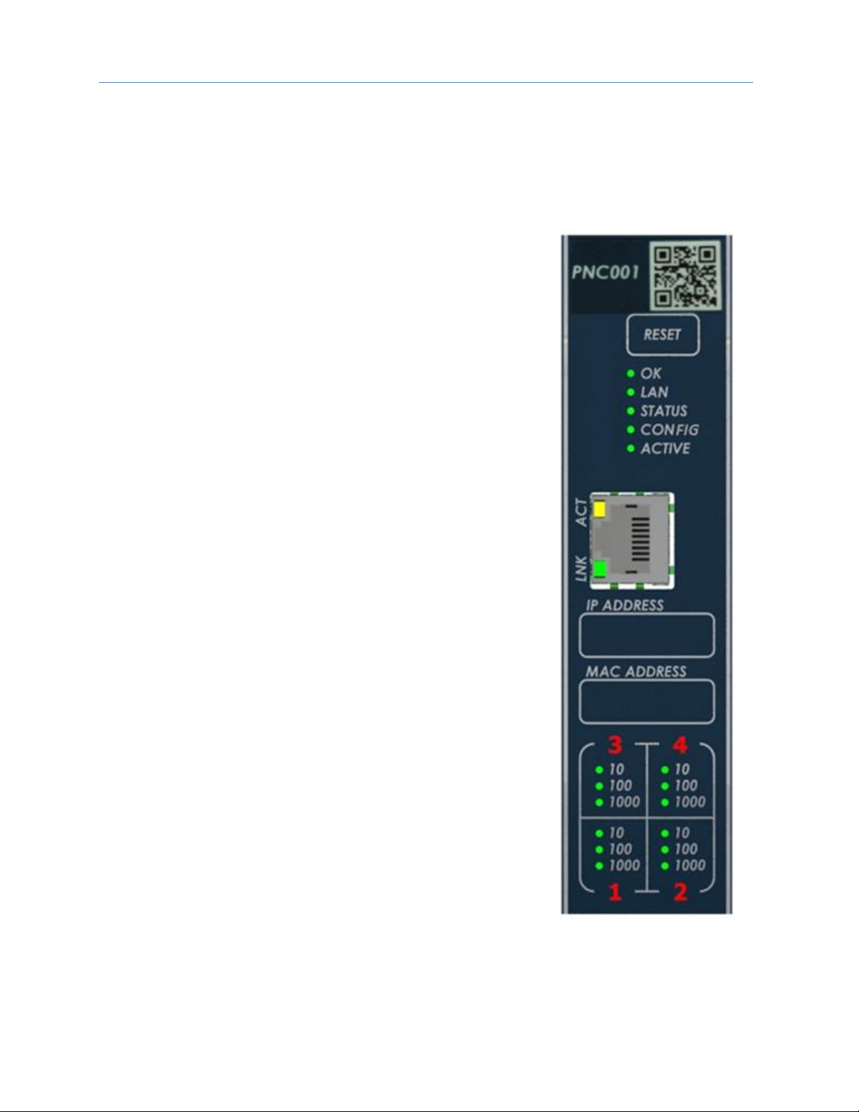
Figure 1: IC695PNC001-Bxxx
Front View
Page 16

Chapter 1. Introduction
GFK-2571N May 2018 5
1.2.2 Embedded PROFINET Controller
CPE400, CPE330 and CPE100/CPE115 feature an Embedded PROFINET IO-Controller function. This feature
permits LAN2 to be configured as a PROFINET Controller similar to PNC001 in functionality, but without
requiring the presence of a PNC001 rack-mounted module.
In the following Specifications section, the physical specifications related to rack mounting do not apply to the
embedded PROFINET Controllers. Refer to the corresponding product documentation for CPE400, CPE330 and
CPE100/CPE115 in the PACSystems RX7i, RX3i and RSTi-EP CPU Reference Manual, (GFK-2222AB or later).
Page 17

Chapter 1. Introduction
6 PACSystems* RX3i & RSTi-EP PROFINET IO-Controller User Manual GFK-2571N
1.3 PNC001 Module Specifications
PROFINET Support
PROFINET Version 2.2 General Class A IO-Controller
Redundantly controlled operation conforms to PROFINET V2.3 Type S-2
System Redundancy.
Note that the CPE100/CPE115 is a simplex PROFINET IO-Controller.
CPU Compatibility
Requires CPU315, CPU320, CPE305, CPE310 or CPE330 with firmware
version 7.0 or higher. Also compatible with all versions of CPE302.
Simplex or redundantly-controlled PROFINET I/O requires CRU320 release
8.00 or higher.
For the current status of CPE330 features refer to PACSystems RX7i, RX3i
and RSTi-EP CPU Reference Manual, (GFK-2222Z or later).
Note that CPE400 and CPE100/CPE115 features an embedded PROFINET
IO-Controller; these are standalone CPUs and do not support
IC695PNC001.
Power Requirements1 ,
Rev. –Ax:
Rev. –Bxxx:
with no SFP devices installed
3.3Vdc: 0.5A
3.3Vdc: 0.5A
with two SFP devices installed, 0.35A per SFP
3.3Vdc: 1.2A maximum
3.3Vdc: 1.2A maximum
5 Vdc: 1.5A maximum
5 Vdc: 0.75A maximum
Operating Temperature Range1
Rev. -Axxx:
0°C to 60°C
Rev. -Bxxx:
-25°C to 60°C
Note: See section 1.4 for de-rating conditions
Number of PROFINET Port Connectors1
PNC001 –2 RJ45 and 2 SFP Cages located on the underside of module
(SFP devices not included, available separately).
Embedded PROFINET IO-Controller – 2 RJ45.
Front Panel Connectors1
PNC001-Ax: One micro USB for communication with a computer using
Command Line Interface.
PNC001-Bxxx: One RJ45. Disabled.
Command Line Interface Supported
PNC001-Ax – Yes. PNC001-Bxxx: No.
Embedded PROFINET IO-Controller – No.
LAN1
IEEE 802.2 Logical Link Control Class I
IEEE 802.3 CSMA/CD Medium Access Control 10/100/1000 Mbps
Maximum I/O Memory
128 Kbytes of combined input/output memory per PROFINET Controller
Note: RSTi-EP CPE100/CPE115 supports a maximum of 8 IO Devices.
The combined input and output memory is equivalent to the input
/output memory requirements of those 8 devices.
Hot-swappable
PNC001 – Yes;
Embedded PROFINET IO-Controller – No.
CPU Status Bits
32
PROFINET IO-Device Data Update Rates
on the PROFINET Network
Configurable: 1ms, 2ms, 4ms, 8ms, 16ms, 32ms, 64ms, 128ms, 256ms and
512ms
Note: For CPE100/CPE115, Update Rates below 16ms are not
recommended.
Number of IP Addresses
One
Number of MAC Addresses
PNC001 – 5. One per external PROFINET port and one internal.
Embedded PROFINET IO-Controller – 1.
1
For CPE400, CPE330 and CPE100, CPE115 refer to the equivalent product specifications in the PACSystems RX7i, RX3i and
RSTi-EP CPU Reference Manual, (GFK-2222Z or later).
Page 18

Chapter 1. Introduction
GFK-2571N May 2018 7
System Maximum Limits
PROFINET Controllers per RX3i CPU
Four PNC001 maximum. Must be located in main CPU rack. Cannot be
located in a remote node.
CPE330 supports one embedded PROFINET Controller plus up to four
PNC001.
CPE400 & CPE100/CPE115 support one embedded PROFINET Controller.
Since these are standalone CPUs they do not support any PNC001 in their
hardware configuration.
IO-Devices per IO-Controller
128 max per PNC001 at maximum update interval.
32 max (simplex) or 20 max (Hot Standby Redundancy) per embedded
PROFINET Controller at maximum update interval.
8 max per RSTi-EP CPE100/CPE115 embedded PROFINET Controller.
For limits at shorter update intervals, refer to PROFINET Controller Loading
Limits in Chapter 3.
Max MRP Clients when configured as MRP
Manager
PNC001 – 63
Embedded PROFINET Controller - 31
Embedded PROFINET Controller CPE100/CPE1152 - 8
IO-Devices per Network
Maximum of 255 simplex or 255 redundant I/O Devices per network,
spread across a maximum of 8 I/O Controllers.
The actual total number of devices supported per network depends on the
topology. For details, refer to Maximum Number of Nodes per Network
based on Topology, below.
IO-Devices per RX3i CPU
Maximum of 255 simplex or 255 redundant I/O Devices per RX3i CPU,
spread across up to four PROFINET Controllers.3
IO-Devices per RSTi-EP CPU
Maximum of 8 simplex I/O Devices for CPE100/CPE115.
IO-Controllers per Network
Eight maximum
Input and output memory per IO-Controller
Maximum of 128 Kbytes combined input and output memory
Note: RSTi-EP CPE100/CPE115 supports maximum 8 IO Devices so the
combined input and output memory is equivalent to maximum input
/output memory supported by 8 devices.
Number of PROFINET Slots per device
256
Number of PROFINET Subslots per slot
256
Number of PROFINET Submodules per RX3i
CPU
2048
Programmer Limits
Number of IO-Controllers
128 (32 RX3i CPU targets × 4 IO-Controllers per RX3i CPU)
Number of IO-Devices
2048 (128 per network × 16 PROFINET networks)
Total number of devices
2176 (does not include backplanes, power supplies, or I/O modules)
For product standards, general operating specifications, and installation requirements, refer to the
PACSystems RX3i System Manual, GFK-2314.
2
Effective with firmware v9.30, CPE100/CPE115 supports MRP.
3
In the case of CPE330, with embedded PROFINET activated, it is possible to have five PROFINET Controllers. However, in
the rare case of having all 5 PNCs configured on the same LAN, and then invoking redundancy, each CPU is again
restricted to a limit of 4 PNCs (in order to satisfy the overall limit of 8 PNCs per LAN).
Page 19

Chapter 1. Introduction
8 PACSystems* RX3i & RSTi-EP PROFINET IO-Controller User Manual GFK-2571N
Maximum Number of Nodes per Network based on Topology
• For a network using MRP ring topology, the maximum number of nodes is 64 (consisting of the PNC001
PROFINET Controller(s) plus up to 62 or 63 IO-Devices). If the ring uses Media Redundancy Protocol, this
means one Media Redundancy Manager and up to 63 clients.
• For a network using MRP ring topology and an Embedded PROFINET IO-Controller as the MRP Ring
Manager, the maximum number of nodes is
o for CPE330/CPE400: 32 (1 MRP Manager and 31 MRP clients)
o for CPE100/CPE115: 9 (1 MRP Manager and 8 MRP clients).
• For a network using star topology, the maximum number of nodes configurable is 263 (consisting of up to
8 PNC001 PROFINET Controllers plus up to 255 IO-Devices).
• For a network using star, line topology, or MRP Ring (where the Embedded PROFINET IO-Controller is not
the MRP Ring Manager) the maximum number of nodes configurable of the system is 264. This may consist
of up to eight IC695PNC001 PROFINET Controllers and one Embedded PROFINET IO-Controller (CPE400 or
CPE330) plus up to 255 I/O-Devices.
Page 20

Chapter 1. Introduction
GFK-2571N May 2018 9
1.4 Operating Range for Surrounding Air Temperature
PNC001-AX
0 to 60°C surrounding air temperature
PNC001-BXXX
-25 to 60°C surrounding air temperature
1.4.1 Operating Temperature De-Rating:
The operating temperature range is specified for the module and not the system as a whole. As a
guideline, if the module is next to hot neighbor modules on each side the maximum operating
ambient temperature should be de-rated as described below:
• If 100 MB Fiber SFPs installed, then reduce by 5°C
• If Copper SFPs operating at 1 GB, then reduce by 6°C
Page 21
Chapter 1. Introduction
10 PACSystems* RX3i & RSTi-EP PROFINET IO-Controller User Manual GFK-2571N
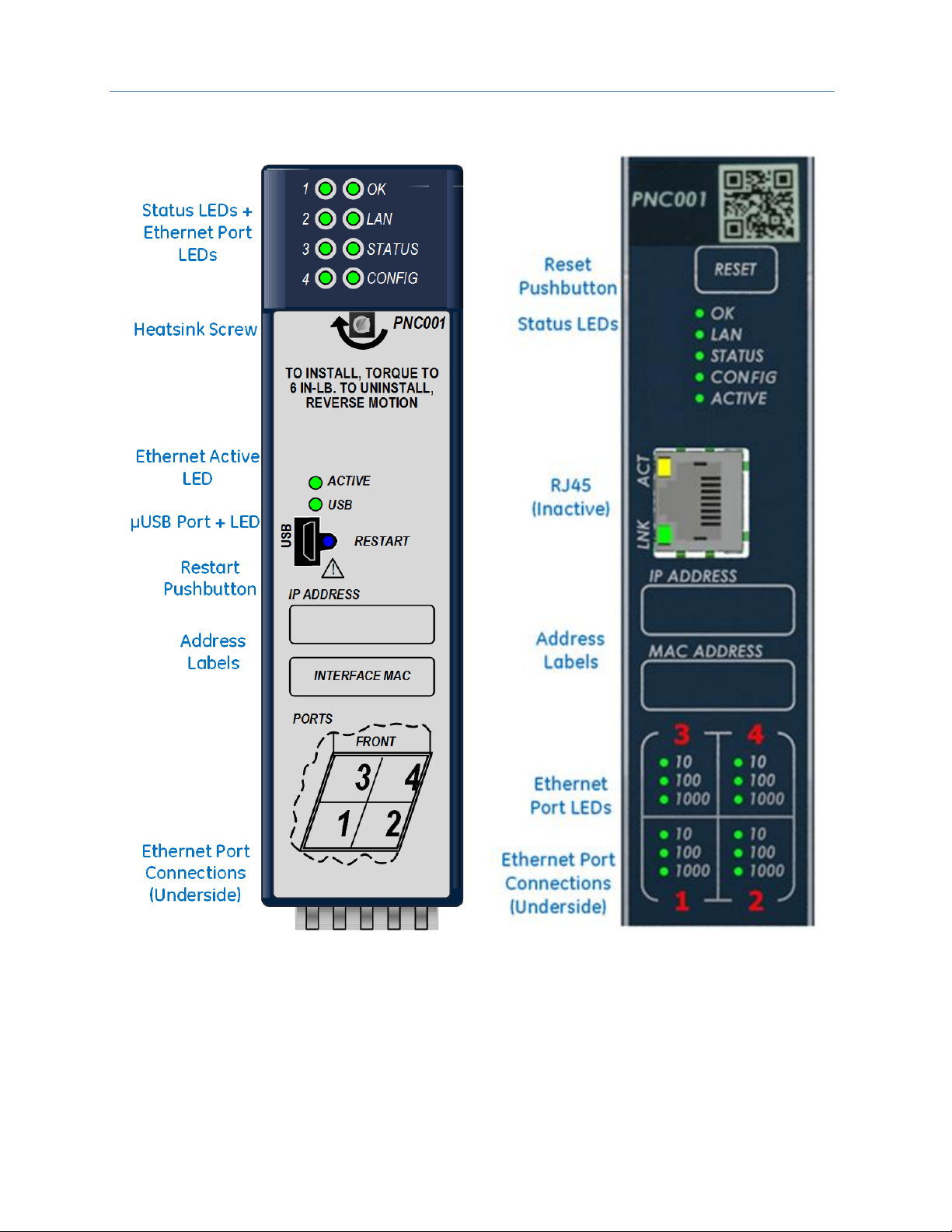
1.5 PNC001 Module Controls and Indicators
Figure 2: IC695PNC001-Ax Controls & Indicators
Figure 3: IC695PNC001-Bxxx Controls &
Indicators
Page 22

Chapter 1. Introduction
GFK-2571N May 2018 11
1.5.1 PNC001 Hardware Implementions (-Ax & -Bxxx)
In January 2018, an updated hardware implementation(-Bxxx) replaced the earlier version (-Ax) of the rackmounted PNC001. The following are the differences between these two hardware implementations.
Topic
-Ax
-Bxxx
Appearance
Figure 2
Figure 3
Case
Plastic
Metal
Attachment to Rack
Via plastic case latch and heatsink screw
Via two Phillip’s head machine screws
Heatsink
Remove plastic knockout from rack
No knockout removal required
Status LEDs
6 LEDs
5 LEDs (no USB LED)
LED Behavior
See Section 2.8
See Section 2.8
Ethernet Port LEDs
4 singleton LEDs (top of faceplate)
4 banks of LEDs (bottom of faceplate)
The digits representing the port
numbers are backlit by LEDs.
µUSB Port
Present
Absent
Command Line
Interface
Uses µUSB Port
Not available
RJ45 Connector on
Faceplate
Absent
Present (Disabled)
Power Requirements
Higher (see Section 1.3)
Lower (see Section 1.3)
Operating
Temperature Range
0 to 60°C
-25 to 60°C
Module Reset
Pushbutton “Restart”
Membrane “Reset”
With the exception of the Command Line Interface, the -Bxxx version is functionally compatible with the -Ax
version.
Page 23
Chapter 1. Introduction
12 PACSystems* RX3i & RSTi-EP PROFINET IO-Controller User Manual GFK-2571N
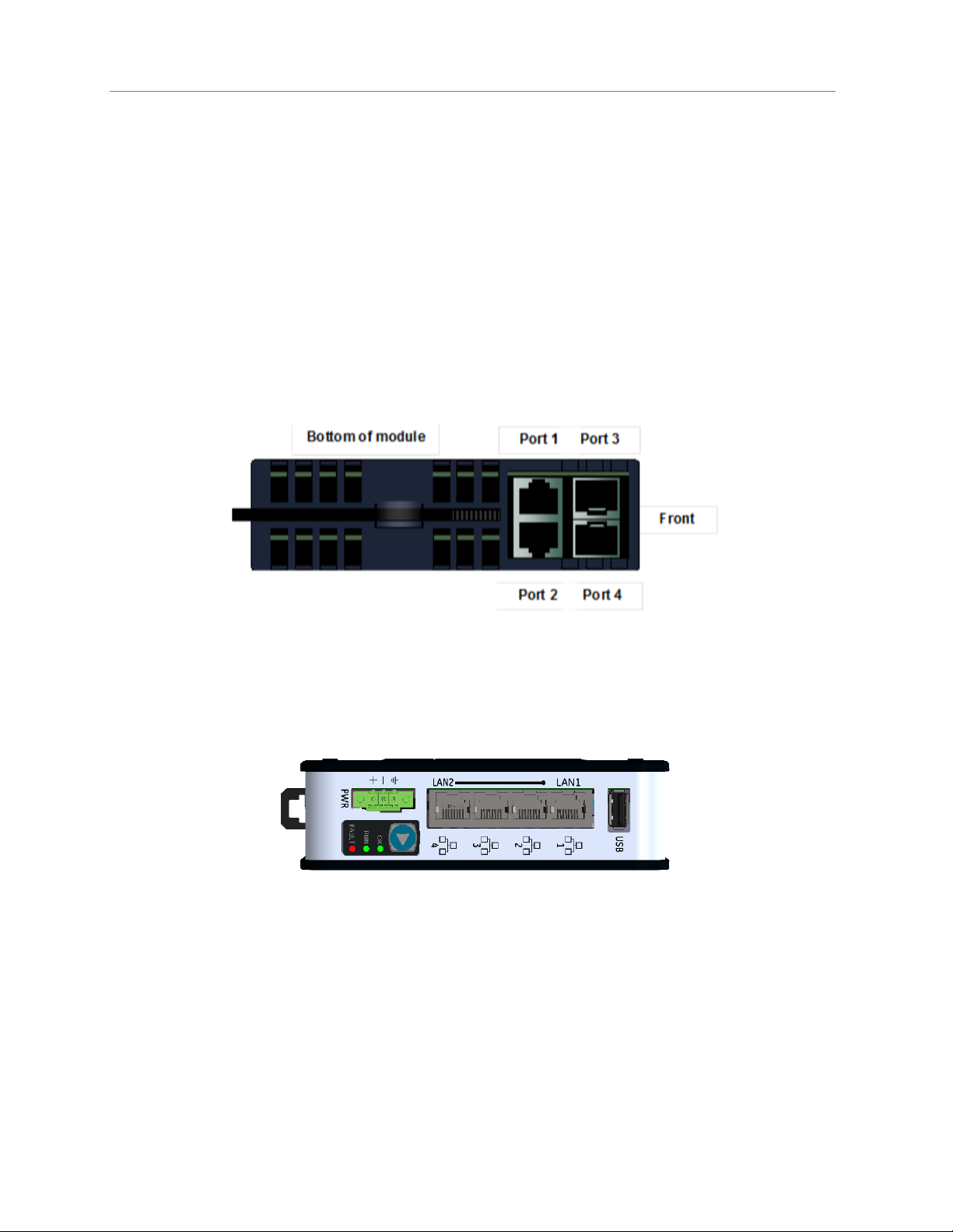
1.5.2 Ethernet Network Ports
Figure 4 shows the underside of the PNC001 module.
• Ports 1 and 2 are standard RJ45 connections.
• Ports 3 and 4 offer Small Form-factor Pluggable (SFP) cages
The PROFINET Controller connects to a PROFINET network via one or more of its four external switch ports.
Two 8-conductor RJ45 shielded twisted pair 10/100/1000 Mbps copper interfaces and two SFP cages provide
flexibility in media selection and the ability to use redundant media for the PROFINET network. Use of
redundant media must first be set up in the module configuration. Chapter 6 provides additional information
about Redundant Media.
The PROFINET protocol supported by the PACSystems RX3i PROFINET modules can be sent and received over
any of the four external ports on PNC001.
The PNC001 module is assigned five Ethernet MAC addresses: one for each of the four external Ethernet ports
and one for the internal switch.
Figure 4: PNC001 Ethernet Ports Location and Type
For the Embedded PROFINET LAN (LAN2), CPE400 and CPE330 both provide two RJ45 ports identical to those
shown as Port 1 and Port 2 in Figure 4. The operational behavior, configuration parameters and diagnostics are
also identical. Refer to the corresponding product documentation for further details.
Small Form-factor Pluggable (SFP) cages (like Port 3 and Port 4 in Figure 4) are not offered on CPE400, CPE330
nor on CPE100/CPE115.
Figure 5: CPE100/CPE115 Ethernet Ports Location and Type
The CPE100/CPE115 Embedded PROFINET LAN (LAN2) supports three switched 8-conductor RJ45 shielded
twisted pair 10/100 Mbps copper interfaces ports as shown in Figure 5. The operational behavior, configuration
parameters and diagnostics are identical to PROFINET port of CPE400. Refer to the corresponding product
documentation for further details.
CPE100/CPE115 LAN2 Port 2 and Port 3 have the ability to use redundant media for the PROFINET network.
Use of redundant media must first be set up in the module configuration. Chapter 6 provides additional
information about Redundant Media.
Page 24

Chapter 1. Introduction
GFK-2571N May 2018 13
Ethernet Port Status Indicators
Each external switched port has an associated link-up/link-down status bit that can be monitored by the RX3i
CPU to check the operating status of the port (see Status Reporting in Chapter 5, Diagnostics, for information
about the PROFINET Controller status bits). In addition, the Port Number LEDs on the front of the module
provide a visual indication of the port status.
1.5.3 USB Port(s)
The USB ports on the CPUs that support embedded PROFINET operate independently of the PROFINET
function. Refer to the corresponding product documentation for further details.
The PNC001-Bxxx module has no micro USB port, and therefore does not support the Command Line Interface.
The PNC001-Ax module has a micro USB port for connection to a computer running Windows® 2000, Windows
XP, Windows Vista®, Windows 7 or Windows 10. On the PNC001 module (-Ax version) only, the USB port can
be used to access the Command Line Interface (CLI) function using a terminal emulation application such as
HyperTerminal.
The Command Line Interface function can be used to monitor a PROFINET Controller module and check its
operation. If a problem occurs, the Command Line Interface can be used help determine the cause.
A driver-install application is provided to set up a computer to communicate with the USB port (see Chapter 2,
Installation, for instructions).
1.5.4 Reset Pushbutton
The Reset pushbutton on a PNC001 module can be used to manually reset the module without cycling power.
The restart operation commences when the pushbutton is released.
1.5.5 LEDs on the CPUs with Embedded PROFINET
Refer to the corresponding product documentation for further details.
1.5.6 LEDs on the PNC001 Module
The table below summarizes LED functions on the PNC001 module. More detailed information about error
indications and special blink patterns is given in Chapter 2, Installation and Chapter 5, Diagnostics.
OK
Green ON indicates that the module is able to perform normal operation.
LAN
Indicates network packets are being processed by the network interface (not just passing through the
embedded switch).
STATUS
Indicates the condition of the PROFINET Controller during normal operation. It indicates whether an entry
other than the start-up event is present in the module’s Local Log. STATUS can also indicate whether any of
the MAC addresses are invalid.
CONFIG
Indicates whether the module has received its configuration from the RX3i CPU.
ACTIVE
Indicates the status of PROFINET connections.
USB
Indicates activity on the USB port. (PNC001-Ax only)
Port
LEDs
Indicate link speed, link connection and link activity corresponding to the four possible external Ethernet
ports.
Page 25

Chapter 1. Introduction
14 PACSystems* RX3i & RSTi-EP PROFINET IO-Controller User Manual GFK-2571N
1.6 PROFINET Networks for PACSystems
PROFINET is an open standard for industrial automation that is based on Industrial Ethernet. The PROFINET IO
framework allows the creation of I/O data exchanges between controllers and distributed devices. It also
allows configuration, parameterization, and diagnostics communication between controllers and devices.
Note: The PROFINET Controller operates only in auto-negotiate mode. All PROFINET bus devices and
switches that are connected to the PROFINET Controller should be configured to use autonegotiation.
The following products support PROFINET I/O:
Catalog #
Product
Notes
IC695CPE400
RX3i Standalone CPU with
embedded PROFINET
Controller
LAN2 may be configured as PROFINET Controller
IC695CPE330
RX3i CPU with embedded
PROFINET Controller
LAN2 may be configured as PROFINET Controller
Supports up to 4 PNC001 in its rack
IC695CPUxxx
All other RX3i CPUs without
Redundancy
Supports up to 4 PNC001 in its rack
IC695CRUxxx
All other RX3i CPUs with
Redundancy
Supports up to 4 PNC001 in its rack
IC695PNC001
RX3i Rack-Mounted
PROFINET Controller
Controls IO-Devices on PROFINET network
IC695PNS001
RX3i Rack-Mounted
PROFINET Scanner
Head-End for RX3i I/O Rack. Exchanges I/O data and Alarms
with PROFINET Controller. Scans modules installed in its I/O
Rack.
IC695CEP001
RX3i CEP I/O Drop PROFINET
Scanner
Head-End for RX3i CEP I/O Drop. Exchanges I/O data and
Alarms with PROFINET Controller. Scans modules installed in
its backplane and expansion rack.
IC200PNS001
IC200PNS002
VersaMax PROFINET Scanner
Head-End for VersaMax I/O Rack. Exchanges I/O data and
Alarms with PROFINET Controller. Scans modules installed in
its I/O Rack.
EPSCPE100/CPE115
RSTi-EP Standalone CPU with
embedded PROFINET
Controller
LAN2 may be configured as PROFINET Controller
EPXPNS001
RSTi-EP PROFINET Scanner
Head-End for RSTi-EP I/O system. Exchanges I/O data and
Alarms with PROFINET Controller. Scans modules installed in
its I/O system.
Components of the RX3i PROFINET network consist of a PACSystems RX3i PROFINET Controller
communicating with IO Devices on the PROFINET bus.
The PROFINET Controller may be an embedded PROFINET Controller (CPE400 or CPE330 or CPE100/CPE115)
or a rack-mounted PNC001 module located in the RX3i CPU rack. For rack-mounted PNC001 units, the main
RX3i rack can include up to four PNC001 modules, each communicating with its own high-speed network.
IO Devices on the network can consist of the I/O modules installed in a rack, each containing a PROFINET
Scanner (PNS) as its head-end, such as the GE products listed above. The network may also include a wide
range of third-party IO Devices, such as pressure gauges and motor actuators, that are connected directly to
the PROFINET network.
Page 26

Chapter 1. Introduction
GFK-2571N May 2018 15
1.6.1 Compression
Due to the smaller memory capacities of CPE302, CPE305 and CPE310, these CPUs require "Compression"
when attaching RX3i PNS or CEP to their PROFINET configuration.
• CPE302: User MUST use Target PLC parameter with "Compression" set to HIGH.
• CPE305: User MUST use Target PLC parameter with "Compression" set to MODERATE.
• CPE310: User can use Target PLC parameter "Compression" set to NORMAL.
• All other CPUs: User can choose to use "Compression" or not.
Page 27
Chapter 1. Introduction
16 PACSystems* RX3i & RSTi-EP PROFINET IO-Controller User Manual GFK-2571N
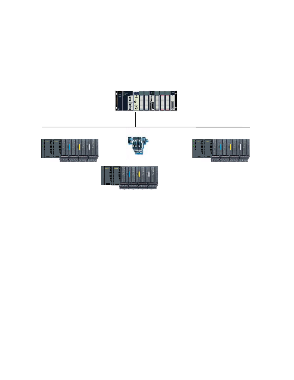
1.6.2 Basic System: One RX3i CPU and One PROFINET Controller using
a single port
Figure 6 shows a basic system with one PACSystems RX3i CPU node having one PROFINET Controller, and one
PROFINET network with three VersaMax Scanners and one third-party IO-Device. Up to 128 IO-Devices can be
installed on an RX3i PROFINET network. The VersaMax PNS and many types of third-party IO-Devices interface
multiple devices such as I/O modules to the PROFINET network.
IO-Device 1
IO-Device 2
IO-Device 64
3
rd
Party
IO-Device 3
RX3i CPU Node with
PROFINET Controller
PROFINET IO LAN
. . .
Figure 6: RX3i System with one PROFINET Controller and one PROFINET LAN
.
Page 28
Chapter 1. Introduction
GFK-2571N May 2018 17
1.6.3 Basic System: One RX3i CPU and One PROFINET Controller using
multiple ports
The illustration below shows a basic system with one PACSystems RX3i CPU node that has one RX3i PROFINET
Controller module controlling one PROFINET network. The network can connect up to 128 compatible IODevices, including any combination of GE PROFINET Scanners and third-party IO-Devices.
Figure 7 shows one RX3i PROFINET Controller that is directly connected to four separate IO-Devices in a Star
topology. Although each IO-Device is connected to a separate Ethernet port on the PNC001, they are all on the
same network segment (IO LAN1). The IO-Devices in this example are all VersaMax PROFINET Scanners, but
RX3i PROFINET Scanners (PNS001) and third-party IO-Devices may also be used.
IO-Device
IO LAN 1
IO LAN 1
IO LAN 1
IO LAN 1
RX3i CPU Node
w/ one PNC
IO-Device
IO-Device
IO-Device
Figure 7: RX3i System with one PROFINET Controller and multiple PROFINET LANs
Page 29
Chapter 1. Introduction
18 PACSystems* RX3i & RSTi-EP PROFINET IO-Controller User Manual GFK-2571N
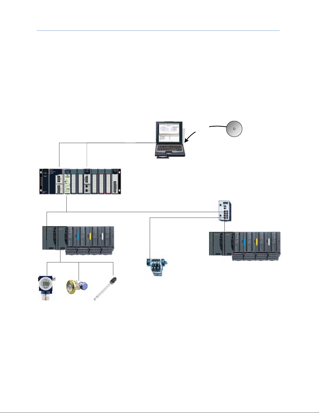
1.6.4 Basic System: Third-Party Devices and PME Programmer
Third-party IO Devices can be used with the RX3i PROFINET Controller if their manufacturer provides a GSDML
file that can be imported into Proficy Machine Edition (PME). The GSDML file defines the characteristics of the
IO-Device and its I/O modules. Importing a third-party IO-Device GSDML file and configuring third-party IODevices are described in Chapter 3, and in the Proficy Machine Edition online help.
After receiving a third-party device’s configuration, the RX3i PROFINET Controller connects to the third-party
IO-Device if the device is available, transfers the configuration to the device, and starts exchanging I/O and
alarm data with the device.
Figure 8 shows a programmer connection (for configuration, user logic programming, and monitoring), the
concept of GSDML import, an optional external Ethernet switch, and the ability to connect field buses to a
PROFINET IO-Device. Third-party IO-Devices that have only one Ethernet port may require the use of an
external switch.
RX3i CPU Node
with PROFINET Controller
Import
Prog/Config Connection
Ethernet
(Optional)
Serial
3rd Party
GSDML File
Programmer (PME)
IO-Device
IO-Device
3rd Party
PROFINET
IO-Device
PROFINET IO LAN
Fieldbus Network
Industrial
Ethernet Switch
(Optional)
Figure 8: RX3i System interfacing with Third-Party Devices and with PME Programmer
Page 30
Chapter 1. Introduction
GFK-2571N May 2018 19
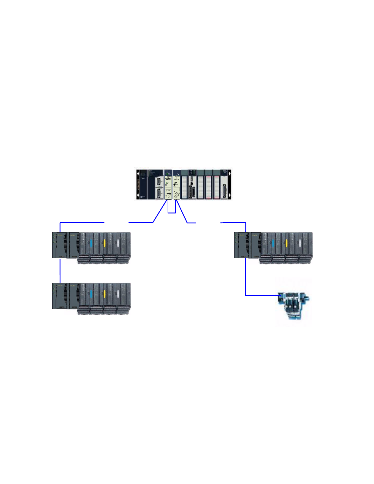
1.6.5 Systems with One RX3i CPU and Two PROFINET Controllers
Both examples in this section show systems with one RX3i CPU that has two PROFINET Controller modules.
The PROFINET network can serve up to 63 IO-Devices (ring topology) or 128 IO-Devices (in star topology).
Note that multiple PNC001 modules in the same rack are not synchronized; that is, no two PNC001 modules
are guaranteed to power up at the same time. PNC001 configuration differences (SFPs, etc.) can also cause
variations in PNC001 power-up times.
If two (or more) PNC001 modules are in a main rack and devices owned by one PNC001 are routed through the
switch on a different PNC001 in the same rack, devices may show a Loss of Device fault followed by an Addition
of Device fault during RX3i power-up because the first PNC001 can power up before the second PNC001 has
enabled its Ethernet switch, causing the Loss of Device. Then when the second PNC001 powers up, the device
will show an Addition of Device fault, which is to be expected under these circumstances. Devices will function
normally once added.
As shown in Figure 9, both PROFINET Controllers are connected to the same network.
IO LAN 1
RX3i CPU Node with
2 PROFINET Controllers
IO-Device 1
IO-Device 2
IO-Device 3
IO-Device 4
IO LAN 1
IO LAN 1
NOTE:
Daisy-chain shown for clarity.
A star or ring topology
is preferred.
Figure 9: RX3i System with two PNC001 Modules and one Daisy-Chain PROFINET LAN
Page 31

Chapter 1. Introduction
20 PACSystems* RX3i & RSTi-EP PROFINET IO-Controller User Manual GFK-2571N
In Figure 10, the two PROFINET Controllers are connected to separate networks. The maximum number of IODevices with multiple PROFINET Controllers in the same RX3i controller is 255.
IO LAN 1
RX3i CPU Node
w/ two PNCs
IO-Device
IO-Device
IO-Device
IO-Device
IO LAN 2
NOTE:
Daisy-chain shown for clarity.
A star or ring topology
is preferred.
Figure 10: RX3i System with two PNC001 modules and two Daisy-Chain PROFINET LANs
Page 32

Chapter 1. Introduction
GFK-2571N May 2018 21
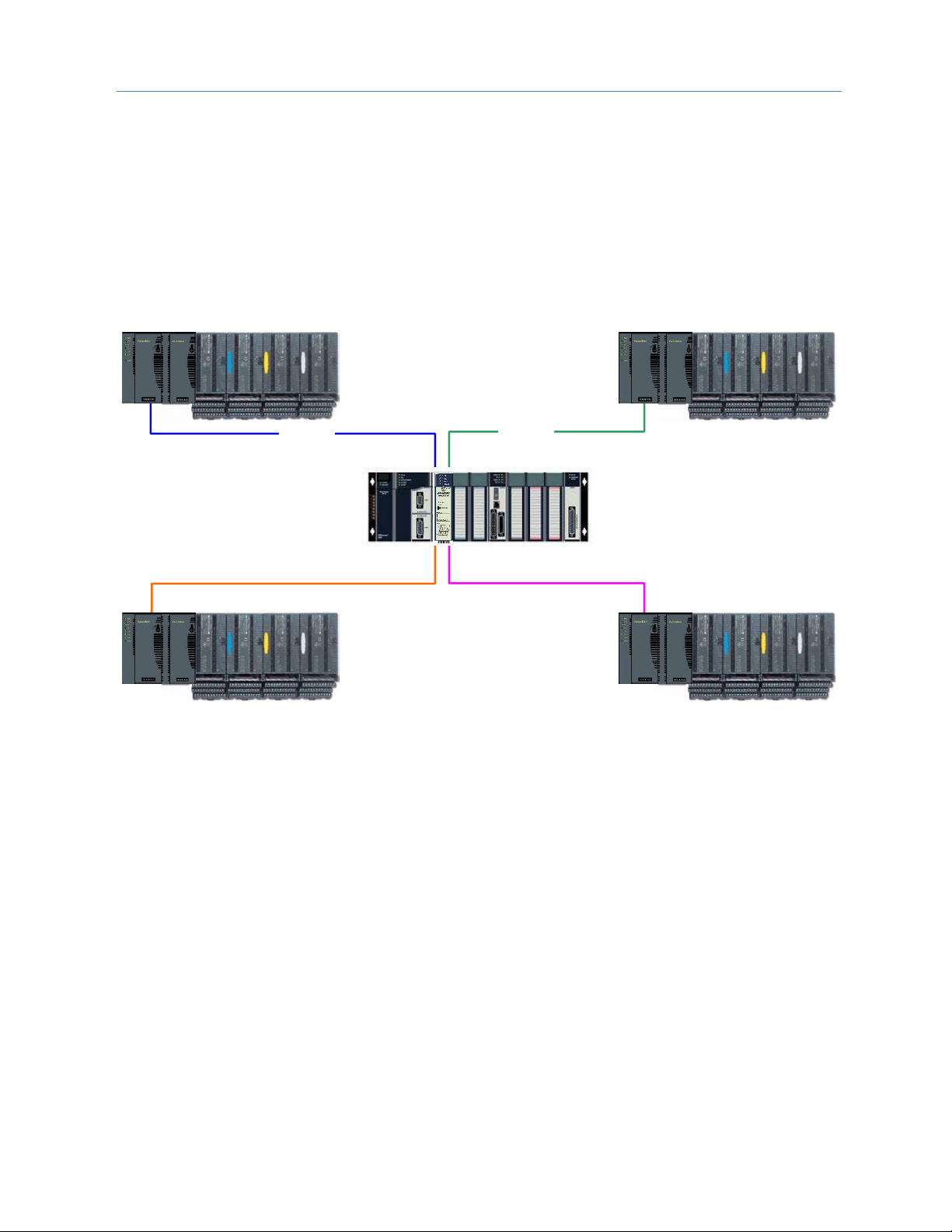
1.6.6 One RX3i CPU with Four Controllers on Separate Networks
Figure 11 shows a system with one RX3i CPU node containing the maximum of four RX3i PROFINET
Controllers, with each PROFINET Controller connected to a different network. In this architecture, up to 255 IODevices are allowed, spread across the four networks. Up to 128 IO-Devices can be controlled by any given
PROFINET Controller.
Note that multiple PNC001 modules in the same rack are not synchronized; that is, no two PNC001 modules
are guaranteed to power up at the same time. PNC001 configuration differences (SFPs, etc.) can also cause
variations in PNC001 power-up times.
If two (or more) PNC001 modules are in a main rack and devices owned by one PNC001 are routed through the
switch on a different PNC001 in the same rack, devices may show a Loss of Device fault followed by an Addition
of Device fault during RX3i power-up because the first PNC001 can power up before the second PNC001 has
enabled its Ethernet switch, causing the Loss of Device. Then when the second PNC001 powers up, the device
will show an Addition of Device fault, which is to be expected under these circumstances. Devices will function
normally once added.
IO-Device
IO-Device
IO-Device
IO-Device
IO LAN 1
IO-Device
IO-Device
IO-Device
IO-Device
IO LAN 2
IO LAN 4
IO LAN 3
RX3i CPU Node
with four PNCs
Daisy chain shown for clarity.
A star or ring topology is
preferred.
Note:
Figure 11: RX3i System with four PNC001 modules and four Daisy-Chain PROFINET LANs
As in the other examples, other GE IO-Devices can be substituted for the VersaMax PROFINET Scanners.
Page 33

Chapter 1. Introduction
22 PACSystems* RX3i & RSTi-EP PROFINET IO-Controller User Manual GFK-2571N
1.6.7 Two RX3i CPUs with Two PROFINET Networks and One Ethernet
Network
Figure 12 shows two RX3i CPU nodes, each with one RX3i PROFINET Controller module and one RX3i Ethernet
Transmitter Module (ETM). The PROFINET Controller modules are connected to separate networks (IO LAN1
and IO LAN2 in the illustration). IO LAN1 and IO LAN2 are used for PROFINET IO traffic.
The RX3i Ethernet Transmitter Modules are connected to the same Ethernet LAN (LAN3 in the illustration).
Proficy Machine Edition (PME), HMI, and Historian use LAN3 to configure and monitor the application. LAN3 is
also used for inter-node communication such as EGD, SRTP, and Modbus/TCP. The three separate networks do
not compete for network bandwidth or interfere with one another.
IO-Device 1
IO-Device 2
IO-Device 2
IO-Device 1
RX3i Controller CPU Node
with one PROFINET
Controller and one ETM
IO LAN 1
IO LAN 2
IO-Device 3
Prog/Config
Connection
LAN 3
EGD/SRTP/ModbusTCP/etc.
Programmer
(PME)
Proficy HMI
Historian
NOTE:
RX3i Controller CPU Node
with one PROFINET
Controller and one ETM
Daisy-chain shown for
clarity. A star or ring
topology is preferred.
Figure 12: RX3i System with two PROFINET LANs & one Ethernet LAN
Page 34

Chapter 1. Introduction
GFK-2571N May 2018 23
1.6.8 Systems that use PROFINET System Redundancy (PNSR)
PACSystems support S2 type PNSR, as diagrammed in Figure 13. The ‘S’ denotes that the IO Device has single
network support. PROFINET defines an ‘R’ option in which the IO Device may have redundant network
interfaces which could be on different networks. The ‘2’ denotes that the network supports two connections as
a set.
Note that in each case the firmware installed in the PROFINET Controller and in the PROFINET Device must
themselves support PNSR. PNSR allows a set of Hot standby CPU controllers to have an active and hot backup
connection to an IO device, so that if something fails in one CPU controller, the other CPU controller can
continue IO operations without disruption.
PNSR relies entirely on PROFINET features to support this configuration. PACSystems only supports PNSR in
Dual HWC Hot Standby systems. Within a PNSR system, simplex IO devices may be controlled by one CPU
Controller in addition to redundant IO devices which are controlled by the Active CPU of the Hot Standby
system. When the CPU controller which is controlling a simplex IO Device is stopped, that IO Device is lost.
The PROFINET PNSR Network may be either Ring or Star formation. Using a Ring formation with the Media
Redundancy Protocol (refer to Chapter 6), is often useful with PNSR systems since a single cable failure is
handled by MRP allowing both IO Controllers to maintain connection with the IO devices.
Figure 13: PROFINET System Redundancy S2
Page 35

Chapter 1. Introduction
24 PACSystems* RX3i & RSTi-EP PROFINET IO-Controller User Manual GFK-2571N
1.6.9 Systems that use Hot Standby CPU Redundancy
Figure 14 shows a Hot Standby CPU Redundancy system that uses a PROFINET I/O network with
MRP ring topology. Use of MRP ring topology is recommended because it eliminates the I/O network
as a single point of failure. If elimination of a single point of failure is not required, a star topology can
be used.
These systems are described in the PACSystems Hot Standby CPU Redundancy User’s Manual,
GFK-2308F or later.
1.6.9.1 Hot Standby CPU Redundancy Network with MRP Ring Topology
IOIOIOI
O
P2P
1
P
N
S
P
S
C
P
U
R
M
X
R
M
X
P
N
C
E
T
M
P
S
C
P
U
R
M
X
R
M
X
P
N
C
E
T
M
IOIOIOI
O
P2P
1
P
N
S
Redundancy Links
RX3i
Primary
Controller
RX3i
Secondary
Controller
HMI
PME
HMI
Historian
Redundant IP
IOIOIOI
O
P2P
1
P
N
S
IOIOIOI
O
P2P
1
P
N
S
P
S
P
S
Remote IO Device Remote IO Device Remote IO Device Remote IO Device
Supervisory Ethernet Network
(Up to 8 separate networks
allowed)
PROFINET I/O Network
RING
(Up to 4 separate networks allowed)
Figure 14: RX3i Hot Standby CPU Redundancy Network with MRP Ring Topology
Page 36

Chapter 1. Introduction
GFK-2571N May 2018 25
1.6.10 RSTi-EP Standalone CPU with embedded PROFINET Controller
using a single port
Figure 15 shows a basic system with one PACSystems RSTi-EP CPU node with embedded PROFINET Controller,
and one PROFINET network with two VersaMax, one RSTi-EP Scanners and one third-party IO-Device. Up to 8
IO-Devices can be installed on an RSTi-EP PROFINET network.
IO-Device 1
IO-Device 2
IO-Device 8
3
rd
Party
IO-Device 3
RSTi-EP EPSCPE100
With Embedded
PROFINET
PROFINET IO LAN
. . .
Figure 15: RSTi-EP System with embedded PROFINET Controller and one PROFINET LAN
Page 37

Chapter 1. Introduction
26 PACSystems* RX3i & RSTi-EP PROFINET IO-Controller User Manual GFK-2571N
1.6.11 RSTi-EP Standalone CPU with embedded PROFINET Controller
using multiple ports
The illustration above shows a basic system with one PACSystems RSTi-EP CPU node with embedded
PROFINET Controller controlling one PROFINET network. The network can connect up to 8 compatible IODevices, including any combination of GE PROFINET Scanners and third-party IO-Devices.
Figure 16 shows one RSTi-EP CPE100/CPE115 embedded PROFINET Controller that is directly connected to
three separate IO-Devices in a Star topology. Although each IO-Device is connected to a separate Ethernet
port, they are all on the same network segment (IO LAN1). The IO-Devices in this example are one VersaMax
two RSTi-EP PROFINET Scanners, but RX3i PROFINET Scanners (PNS001) and third-party IO-Devices may also
be used.
Figure 16: RX3i System with one PROFINET Controller and multiple PROFINET LANs
Page 38

Chapter 1. Introduction
GFK-2571N May 2018 27
1.6.12 RSTi-EP Standalone CPU with embedded PROFINET Controller
using MRP
Figure 17 shows one RSTi-EP CPE100/CPE115 embedded PROFINET Controller that uses a PROFINET
I/O network with MRP ring topology. CPE100/CPE115 LAN2 Port 2 & Port 3 support Media
Redundancy and on configuring MRP as Manager / Client LAN2 Port 4 can be used for connecting
Simplex PROFINET devices or any other Ethernet Protocols such as Modbus, SRTP, and EGD. Use of
MRP ring topology is recommended because it eliminates the I/O network as a single point of failure.
If elimination of a single point of failure is not required, a star topology can be used.
Figure 17: RX3i System with one PROFINET Controller and PROFINET IO Network MRP
Page 39

Chapter 1. Introduction
28 PACSystems* RX3i & RSTi-EP PROFINET IO-Controller User Manual GFK-2571N
1.7 Glossary
AR
Application Relationship. PROFINET term for a relationship that is established between an
IO-Controller/Supervisor and IO-Device. For any data to be exchanged between an IOController/Supervisor and a given IO-Device, an Application Relationship must be established.
Within the Application Relationship, various Communication Relationships (CRs) are then
established for the different types of data to be exchanged.
Broadcast
In Ethernet, the transmission of a network message to all hosts on the network.
CLI
Command Line Interface
CPU Node
In a PACSystems RX3i PROFINET network, a CPU Node is a node in which a PACSystems RX3i CPU
is connected to the PROFINET network.
CR
Communication Relationship. PROFINET term for a channel that is established within an
Application Relationship (AR) to transfer specific data between an IO-Controller/Supervisor and a
given IO-Device. Multiple CRs are established within an AR to transfer data.
Critical
Network Port
An Ethernet port connection on the PROFINET I/O Controller that is configured as a critical port.
When the last Critical Network Port is disconnected from its network, a diagnostic fault is logged.
In a redundancy system where the PROFINET I/O Controller is controlling redundant devices, this
results in a CPU redundancy role-switch with the CPU placed into Stop/Fault mode.
DAP
Device Access Point. This access point is used to address an IO-Device as an entity.
Gratuitous
ARPs
An Address Resolution Protocol (ARP) request sent by the host to resolve its own IP Address.
GSDML
General Station Description Markup Language - definition of PROFINET Device Characteristics.
IOC
PROFINET IO-Controller
IOD
PROFINET IO-Device
IOCR
Input Output Communication Relationship – describes the type (input/output) and amount of I/O
data to be transferred, the sequence of the transfers and the transfer cycle between a PROFINET
IO-Controller (or IO-Supervisor) and a PROFINET IO-Device.
IOCS
PROFINET Input/Output Consumer Status is transmitted on the PROFINET network to provide
feedback on Input Data for an IO controller and Output Data for an IO device.
IOPS
PROFINET Input/Output Provider Status is transmitted on the PROFINET network to provide
feedback on Output Data for an IO controller and the Input Data for an IO device.
IOxS
PROFINET abbreviation for the IOCS and/or IOPS (see above).
LLDP
Link Layer Discovery Protocol. IEEE standardized protocol used by network devices to advertise
their identity and capabilities.
LLDPDU
Link Layer Discovery Protocol Data Unit.
MAC
Media Access Control address (MAC address)
MAU
Medium Attachment Unit
MIB
Management Information Basis
MRC
Media Redundancy Client. Within Media Redundancy Protocol, an MRC is responsible for helping
the MRM detect breaks/no breaks in the ring.
MRM
Media Redundancy Manager. Within Media Redundancy Protocol, an MRM is responsible for
ensuring that the ring does not have a closed loop, while simultaneously ensuring maximal
connectivity between nodes on the ring.
MRP
Media Redundancy Protocol. An Ethernet protocol that provides redundant paths for PROFINET-IO
cyclic traffic by supporting a ring topology.
Multicast
In Ethernet, the transmission of a network message to all hosts within a host group.
NOS
Name of Station
OID
Object Identifier
Phase
If the IOCR Update Period is greater than the Send Clock time, the Update Period is divided into
multiple phases where each phase is equal to one Send Clock.
Page 40

Chapter 1. Introduction
GFK-2571N May 2018 29
Glossary, continued
PNC
PROFINET Controller: Typically, the generic PROFINET Controller function. PNC001 represents a
slot-mounted product (IC695PNC001). Embedded PROFINET Controllers may be configured on
LAN2 for CPE400, CPE330 and CPE100/CPE115. Both embedded and slot-mounted perform the
same functions on the PROFINET network, but there are differences to be noted in installation,
configuration, operation and performance.
PNS
PROFINET Scanner. Head-end module that controls I/O in rack and communicates with PROFINET
network. Both RX3i (IC695PNS001) and VersaMax (IC200PNS001, IC200PNS002) modules are
discussed in this manual.
PNSR
PROFINET System Redundancy: the PROFINET processes and mechanisms by which an IO-Device
is controlled by multiple IOCs in redundant PLCs.
RDO
Record Data Object. Services used to read and write structured data stored in a PROFINET IO-
Device.
Reduction Ratio
Along with Send Clock determines the Update Period for a PROFINET cyclic data transfer between
two devices (see IOCR). The Update Period equals the Reduction Ratio multiplied by the Send Clock
time. For example, if the Reduction Ratio is 4 and the Send Clock is 1ms, the Update Period is 4ms.
Remote Node
For an RX3i PROFINET network, a Remote Node is any PROFINET IO-Device, such as a rack of I/O
modules with a Remote Scanner or a third party PROFINET IO-Device.
RIV
Reference ID Variables
RTA
Real-Time Acyclic. A PROFINET-IO Mechanism used to exchange non-periodic data such as alarms.
RTC
Real-Time Cyclic. A PROFINET-IO Mechanism used to exchange input and output data.
Send Clock
Value between 1 and 128 inclusive in units of 31.25 µs (equivalent to a range of 31.25 µs to 4 ms)
used to calculate the Update Period for a PROFINET cyclic data transfer between two devices (see
IOCR). The Send Clock is the basis for all other scheduling parameters.
Send Offset
The time to delay a scheduled PROFINET cyclic data transfer frame.
Measured in nanoseconds from 0 to 3,999,999. Must be less than the Send Clock time.
SFP
Small Form-factor Pluggable. Pluggable, hot-swappable transceivers.
SNMP
Simple Network Management Protocol. UDP-based network protocol that facilitates the exchange
of management information between network devices.
Status Bits
Module status data in RX3i CPU reference memory.
Submodule
PROFINET-IO representation of the smallest configurable entity of a PROFINET Module.
SVC_REQ
Service Request Function Block. A control system service initiated by the RX3i CPU.
TLV
Type-Length-Value
Unicast
In Ethernet, the transmission of a network message to an individual host.
Update Period
The time between PROFINET cyclic data transfers between an IO-Controller and an IO-Device.
USB
Universal Serial Bus
WinLoader
A software utility used to download and install firmware upgrades via a serial port.
Page 41

Chapter 1. Introduction
30 PACSystems* RX3i & RSTi-EP PROFINET IO-Controller User Manual GFK-2571N
1.8 Documentation
PACSystems Manuals
PACSystems RX7i, RX3i and RSTi-EP CPU Reference Manual
GFK-2222
PACSystems RX7i, RX3i and RSTi-EP CPU Programmer’s Reference Manual
GFK-2950
PACSystems Hot Standby CPU Redundancy User Manual
GFK-2308
PACSystems Battery and Energy Pack Manual
GFK-2741
Proficy Machine Edition Logic Developer Getting Started
GFK-1918
Proficy Process Systems Getting Started Guide
GFK-2487
PACSystems RXi, RX3i, RX7i and RSTi-EP Controller Secure Deployment Guide
GFK-2830
RX3i Manuals
PACSystems RX3i System Manual
GFK-2314
PACSystems RX3i PROFINET Controller Command Line Interface Manual
GFK-2572
PACSystems RX3i Max-On Hot Standby Redundancy User’s Manual
GFK-2409
PACSystems RX3i PROFINET Scanner Manual
GFK-2737
PACSystems RX3i CEP PROFINET Scanner User Manual
GFK-2883
PACSystems HART Pass Through User Manual
GFK-2929
PACSystems RX3i PROFINET Scanner Important Product Information
GFK-2573
VersaMax Manuals
VersaMax PROFINET Scanner Manual
GFK-2721
In addition to these manuals, datasheets and product update documents describe individual modules and
product revisions. The most recent PACSystems documentation is available on the support website
www.geautomation.com.
.
Page 42

GFK-2571N May 2018 31
Chapter 2 Installation
This chapter provides instructions for installing PACSystems RX3i PROFINET Controller modules.
• Pre-Installation check
• Removing the backplane knockout
• Module installation and removal
• Hot insertion and removal
• Port connections
• Installing SFP devices
• LED indications
• Installing the USB Port Driver
• Firmware updates
• Time synchronization with RX3i CPU
For additional information about system installation, also refer to the PACSystems RX3i Systems Manual, GFK-
2314.
Page 43

Chapter 2. Installation
32 PACSystems* RX3i & RSTi-EP PROFINET IO-Controller User Manual GFK-2571N
2.1 Pre-Installation Check
Upon receiving your RX3i equipment, carefully inspect all shipping containers for damage. If any part of the
system is damaged, notify the carrier immediately. The damaged shipping container should be saved as
evidence for inspection by the carrier.
As the consignee, it is your responsibility to register a claim with the carrier for damage incurred during
shipment. However, Automation & Controls at GE Energy Connections will fully cooperate with you, should
such action be necessary.
After unpacking the RX3i equipment, record all serial numbers. Serial numbers are required if you should need
to contact Customer Care during the warranty period. All shipping containers and all packing material should
be saved should it be necessary to transport or ship any part of the system.
Verify that all components of the system have been received and that they agree with your order. If the system
received does not agree with your order, contact Customer Care.
If you need technical help, contact Technical Support. For phone numbers and email addresses, see the
Contact Information page in the front of this manual.
Page 44

Chapter 2. Installation
GFK-2571N May 2018 33
2.2 Installation in Hazardous Areas
EQUIPMENT LABELED WITH REFERENCE TO CLASS I, GROUPS A, B, C & D, DIV. 2 HAZARDOUS LOCATIONS IS
SUITABLE FOR USE IN CLASS I, DIVISION 2, GROUPS A, B, C, D OR NON-HAZARDOUS LOCATIONS ONLY
Warning
EXPLOSION HAZARD - SUBSTITUTION OF COMPONENTS MAY IMPAIR
SUITABILITY FOR CLASS I, DIVISION 2.
Warning
EXPLOSION HAZARD - WHEN IN HAZARDOUS LOCATIONS, TURN OFF POWER
BEFORE REPLACING OR WIRING MODULES.
Warning
EXPLOSION HAZARD - DO NOT CONNECT OR DISCONNECT EQUIPMENT
UNLESS POWER HAS BEEN SWITCHED OFF OR THE AREA IS KNOWN TO BE
NON-HAZARDOUS.
Warning
EXPLOSION HAZARD - USB PORT IS ONLY FOR USE IN NON-HAZARDOUS
LOCATIONS, DO NOT USE UNLESS AREA IS KNOWN TO BE NON-HAZARDOUS.
2.2.1 ATEX Marking
II 3 G Ex nA IIC T5 X Ta: 0 - 60C
Page 45

Chapter 2. Installation
34 PACSystems* RX3i & RSTi-EP PROFINET IO-Controller User Manual GFK-2571N
2.3 Removing the Backplane Knockout
The IC695PNC001 must be installed in the main (CPU) rack of the RX3i system, using a Universal Backplane
such as IC695CHS007, CHS012 or CHS016. For details, refer to the PACSystems RX3i System Manual,
GFK-2314.
The rear of the PNC001-Ax module has an exposed heat sink and backplane connector. Before inserting the
module into the backplane, remove the plastic knockout in the slot into which the module will be placed. The
installation slot must match the slot selected for the module in the Proficy Machine Edition (PME) hardware
configuration. This action is not required for PNC001-Bxxx. However, if the knockout has been previously
removed, the PNC001-Bxxx can still be inserted into that slot location.
Figure 18: RX3i Backplane showing Removable Plastic Knockout
Page 46

Chapter 2. Installation
GFK-2571N May 2018 35
2.4 Module Installation
• RX3i rack power may be off or on (see Hot
Insertion and Removal for details).
Figure 19: Install Module into RX3i Backplane
• Holding the module firmly, align the module
with the correct slot and connector.
• Engage the module’s rear pivot hook in the
notch on the top of the backplane (1).
• Swing the module down (2) until the module’s
connector engages the backplane’s backplane
connector, and the release lever (PNC001-Ax
only) on the bottom of the module snaps into
place in the bottom module retainer (3).
• Visually inspect the module to be sure it is
properly seated.
• PNC001-Ax: Tighten the heat sink screw on the
front of the module in the threaded hole in the
back plate to 6 in-lbs (0.68 Nm), using a flat-tip
screwdriver.
• PNC001-Bxxx: Secure the bottom of the module
to the backplane using the two captive Phillip’s
head machine screws provided with the module
(not shown in diagram).
2.5 Module Removal
• RX3i rack power may be off or on (see Hot
Insertion and Removal for details).
Figure 20: Remove Module from RX3i Backplane
• PNC001-Ax: Loosen the heat sink screw on the
front of the module to release the heat sink
from the backplane’s aluminum back plate.
• PNC001-Ax: Locate the release lever at the
bottom of the module and firmly press upward
(1), toward the module.
• PNC001-Bxxx: Loosen the two captive Phillip’s
head machine screws at the bottom of the
module.
• While holding the module firmly and fully
depressing the release lever (PNC001-Ax only),
pivot the module upward until its connector is
out of the backplane (2).
• Lift the module up and away from the
backplane to disengage the pivot hook (3).
Page 47

Chapter 2. Installation
36 PACSystems* RX3i & RSTi-EP PROFINET IO-Controller User Manual GFK-2571N
2.6 Hot Insertion and Removal
Modules in a Universal Backplane can be installed or removed while power is applied to the system. This
includes backplane power and field power supplied to the module. For a full discussion of this topic, refer to the
Hot Insertion and Removal section in the PACSystems RX3i System Manual, GFK-2314.
The PNC001 module must be properly seated with the latch engaged (PNC001-Ax only) and all pins connected
within 2 seconds. For removal, the module must be completely disengaged within 2 seconds. It is important
that the module not remain partially inserted during the insertion or removal process. There must be at a
minimum of two seconds between the removal and insertion of modules.
Warning
Inserting or removing a module with power applied to the system may cause an
electrical arc. This can result in unexpected and potentially dangerous action by
field devices. Arcing is an explosion risk in hazardous locations. Be sure that the
area is non-hazardous or remove system power appropriately before removing
or inserting a module.
Warning
If the surrounding air operating temperature of the PNC001 module is greater
than 40°C (104°F), SFP devices could reach operating temperatures over 70°C
(158°F). Under these conditions, for your safety, do not use bare hands to
remove an SFP device from the SFP cage. Use protective gloves or a tool
(needle-nose pliers) to avoid handling the hot SFP device directly when
removing the SFP device.
Caution
If an RX3i PROFINET Controller is extracted from a powered RX3i backplane, it
loses power immediately, which may result in data loss. Do not remove or
insert the device while downloading hardware configuration to the system.
When the module is plugged back into a powered backplane, the PNC001
module restores data from the internal non-volatile memory. If, however, the
RX3i CPU has configuration data for the PROFINET Controller, it re-delivers the
data to the PNC001 module, superseding parameters previously stored in nonvolatile PNC001 memory.
2.6.1.1 Fault Notifications
Removing a PROFINET Controller causes a Loss of IOC fault in the RX3i CPU’s I/O Fault Table and inserting a
PROFINET Controller causes an Addition of IOC fault in the I/O Fault Table.
Page 48

Chapter 2. Installation
GFK-2571N May 2018 37
2.7 Ethernet Port Connections
Each port on an RX3i PROFINET Controller operates independently. This is true for all ports on the PNC001
module and for ports assigned to embedded PROFINET Controllers. In this way, devices that operate at
different speeds and/or duplex modes may be attached to a compatible port. Each port automatically detects
the attached cable and functions properly with either straight-through or crossover cables.
Note: All PROFINET Controller ports operate in auto-negotiate mode only. All PROFINET devices and
switches that are connected to the PROFINET Controller should be configured to use autonegotiation.
Figure 21: Ethernet Ports on PNC001 Module
2.7.1 PROFINET Network Connections
Connections to the PROFINET Controller can be made using standard cables. The PROFINET Controller can be
connected to only one PROFINET network. However, different devices on the same LAN can be connected via
more than one port.
Note: Shielded cable is required for 1 Gbps operation.
Caution
Do not connect two or more ports on the PROFINET Controller to the same
device, either directly or indirectly, unless Media Redundancy is enabled in
the PROFINET Controller’s configuration. If Media Redundancy will be used,
do not close the network ring until after a Media Redundancy configuration
that contains one node as a Media Redundancy Manager (MRM) has been
downloaded to the PROFINET Controller. If a Media Redundancy Manager is
not present, packets can continuously cycle on the network, preventing
normal operation. For more information refer to Chapter 6, Redundant
Media.
2.7.2 RJ45 Port Connections
The RJ45 ports on the underside of the PNC001 module can be used for PROFINET network connections or for
general Ethernet communications on a 10BaseT, 100BaseTX, or 1000Base-T IEEE 802.3 network. Typical
switches, hubs, or repeaters support 6 to 12 nodes connected in a star wiring topology.
For embedded PROFINET Controllers, LAN2, when configured as an Ethernet port, does not permit PROFINET
functions. However, once configured as a PROFINET Controller, LAN2 continues to support the Ethernet
modality. In other words, it is possible to have Ethernet protocols running on the network while it is configured
for PROFINET. This can be tolerated so long as the Ethernet traffic does not impede or degrade PROFINET
operations.
Page 49

Chapter 2. Installation
38 PACSystems* RX3i & RSTi-EP PROFINET IO-Controller User Manual GFK-2571N
10BaseT: uses a twisted pair cable of up to 100 meters in length between a node and another node, switch,
hub, or repeater. 10Mbs may be used for the Command Line Interface (CLI) and general Ethernet traffic, but
not for PROFINET communications.
100BaseTX: uses a cable of up to 100 meters in length between a node and another node, switch, hub, or
repeater. The cable should be data grade Category 5 or better unshielded twisted pair (UTP) or shielded
twisted pair (STP).
1000BaseT: uses a cable of up to 100 meters in length between a node and another node, switch, hub, or
repeater. The cable should be data grade Category 5 or better shielded cable.
2.7.2.1 Network Cabling and Connector Types
Copper: up to 100 Meters between Devices
All Automation & Controls products from GE Energy Connections use RJ45 connectors for copper connections.
Copper cabling and connections are easily available in the general market and support distances of up to
100m.
Figure 22: Interconnect using Copper Cables / RJ45 Connectors
Multi-Mode Fiber: up to 2 km between Devices
Multi-Mode Fiber supports two types of connectors, LC and SC. The LC connector is used on SFPs on the RX3i
PNC001 and on the PNS modules. The SC connector is used on the VersaMax PNS. Cables are available with
LC-to-LC connectors and LC-to-SC connectors to match the different connector formats. Multi-Mode fiber can
support distances up to 2Km at 100Mbps. When using fiber, pay particular attention to the cable connector
and cable radius clearance requirements in cabinet planning and layout.
Figure 23: Interconnect using Multi-Mode Fiber
Single-Mode Fiber: up to 70 km between Devices
Single-Mode Fiber is supported between SFPs using the LC connector. Single-Mode fiber can support distances
up to 70 km. As with the Multi-mode fiber, pay attention to the cable connector, radius, and minimum length
requirements in planning the installation.
Figure 24: Interconnect using Single-Mode Fiber
Page 50

Chapter 2. Installation
GFK-2571N May 2018 39
2.7.2.2 Network Cabling and Connector Examples
Figure 25: CAT5e/CAT6 (shielded or unshielded) with RJ 45 Connector
Figure 26: Multi-Mode Fiber with LC connector
Figure 27: Single-Mode Fiber with LC connector
Page 51

Chapter 2. Installation
40 PACSystems* RX3i & RSTi-EP PROFINET IO-Controller User Manual GFK-2571N
2.7.3 Installing SFP Devices
SFP (Small Form-Factor Pluggable) devices can be installed in Port 3 and Port 4 of the PROFINET Controller.
See section 2.7.3.1, SFP Modules for Ethernet Ports, for a list of supported SFP devices, media types and
distances. The specific SFP module installed in each cage must be defined in the Proficy Machine Edition
configuration of the PNC001.
Keep the protective plug installed in the SFP device. Following the manufacturer’s installation instructions,
insert the device with its electrical contacts oriented toward the inside of the PNC001 until it clicks into place.
Figure 28: Method for Attaching SFP Device Connector to PNC001 Port
Warning
Optical SFPs use an invisible laser to generate a fiber-optic signal. Always
keep the port covered if a cable is not installed. Do not peer into the open
port if a cable is not installed
Remove the protective plug to install the cable.
When the PNC001 powers up, it automatically detects devices plugged into the SFP cages, their type (fiber,
copper, etc.) and their link speed. If an SFP device has been included in the configuration but is not present in
the specified cage, the PNC001 logs a Loss of Network Port entry to its Local Log Table. If possible, the
PROFINET Controller also logs a fault to the associated RX3i I/O Fault Table. The module continues to operate
with a Loss of Network Port fault.
If the installed SFP device is different from what has been configured, the PNC001 logs a mismatch entry to its
Local Log table. If possible, it also logs an informational fault to the associated RX3i controller’s Fault Table. The
module tries to configure and use the SFP if it is compatible (as listed in SFP Modules for Ethernet Ports). If the
PROFINET Controller detects an unsupported SFP type on power-up or when the SFP is inserted, the PNC001
adds an entry into its Local Log Table and the RX3i I/O Fault Table (if possible) and turns the associated port
LED red.
Page 52

Chapter 2. Installation
GFK-2571N May 2018 41
2.7.3.1 SFP Modules for Ethernet Ports
Each Small Form-Factor Pluggable (SFP) cage on the bottom of a PROFINET Controller module can accept a:
• 10/100/1000 Mbps copper SFP,
• 100Mbps Single-Mode Fiber SFP,
• 100Mbps Multi-Mode Fiber SFP,
• 1000Mbps Single-Mode Fiber SFP, or
• 1000Mbps Multi-Mode Fiber SFP device.
SFP devices can be removed/replaced during module operation. The RX3i PROFINET Controller
supports the SFP devices listed below. An SFP type other than those listed below can be configured
as a GENERIC SFP in Proficy Machine Edition. The RX3i PROFINET Controller will attempt to operate
with a generic SFP that identifies itself as an Ethernet SFP. Since SFP types other than those listed
below have not been validated, correct operation cannot be guaranteed.
SFP Type
Wavelength
(nm)
Media Type
Core Size
(µm)
Modal
Bandwidth (MHz
– km)
Distance
(m)
100BASE-FX
1300
MMF
62.5
500
2 – 2,000 (Full-Duplex)
2 – 400 (Half-Duplex)
50
400
50
500
100BASE-LX10
1300
SMF
9
-
2 – 10,000
1000BASE-SX
850
MMF
62.5
160
2 – 220
200
2 – 275
50
400
2 – 500
500
2 – 550
1000BASE-LX
1300
SMF
9
-
2 – 10,000
1000BASE-ZX
1550
SMF
9
-
2 – 70,000
10/100/1000BASE-T
-
CAT5/CAT5e/CAT
6
-
-
100 (maximum)
Page 53

Chapter 2. Installation
42 PACSystems* RX3i & RSTi-EP PROFINET IO-Controller User Manual GFK-2571N
2.7.3.2 Typical SFP Modules
Below are images of the two types of Ethernet SFPs. The Single- and Multi-Mode Fiber SFPs accept an LC
Connector. The Copper SFPs accept an RJ45 connector.
Figure 29: Fiber SFP showing LC Connector
Figure 30: Copper SFP showing RJ45 Connector
2.7.4 Removing SFP Devices
Warning
If the surrounding air operating temperature of the PNC001 module is greater
than 40°C (104°F), SFP devices could reach operating temperatures over 70°C
(158°F). Under these conditions, for your safety, do not use bare hands to
remove an SFP device from the SFP cage. Use protective gloves or a tool
(needle-nose pliers) to avoid handling the hot SFP device directly when
removing the SFP device.
Remove the cable from the SFP device. If the device has a latching mechanism such as a bale clasp, open it
gently. Do not pull on the latching mechanism. Hold the sides of the SFP device and pull it out of the PROFINET
Controller port.
Page 54

Chapter 2. Installation
GFK-2571N May 2018 43
2.8 PNC001 LED Behavior
2.8.1 Power-up LED Patterns
At power-up, the LEDs show the blink patterns described below. The LEDs also blink diagnostic patterns for
certain operating errors and for module identification. See Chapter 5, Diagnostics for a description of those
special blink patterns.
Step
LED/Blink pattern
Description
Figure 31: PNC001-Bxxx
Front View showing LEDs
1
All LEDs OFF
Normal operation
1.1
ACTIVE LED solid green
(PNC001-Bxxx only)
Normal operation
1.2
CONFIG LED solid green
(PNC001-Bxxx only)
Normal operation
2
STATUS LED solid green
Normal operation
OK LED blinks Amber with
special blink code
Fatal Initialization or Diagnostics Failure,
Hardware Module Identity Information not
available
OK, LAN, and STATUS LEDs
blink green in unison (1 Hz)
Invalid firmware detected. Module is waiting
for firmware update. Blink pattern continues
during firmware update.
3
LAN and STATUS LED solid
green (PNC001-Ax only)
Normal operation
4
LAN LED solid green
Normal operation
LAN and STATUS LED blink
green (1 Hz)
Update of module firmware. After the
automatic update completes, the LEDs blink
Amber and the module resets, which restarts
the power-up process.
5
OK LED solid green
Normal operation. Power up completed and
backplane communications established.
OK LED blinks green (1 Hz)
Module power-up completed, but
communication not yet established over the
RX3i backplane.
Note: Under certain ambient operating temperatures, the PROFINET Controller may momentarily display
the overtemperature pattern during power up, while it is calibrating its thermal protection functions.
This indication may be ignored, and no overtemperature entry is added to the Local Log table, the
Controller Fault Table or I/O Fault Table.
For details, see Special LED Blink Patterns in Chapter 5, Diagnostics.
Page 55

Chapter 2. Installation
44 PACSystems* RX3i & RSTi-EP PROFINET IO-Controller User Manual GFK-2571N
2.8.2 Detailed LED Descriptions
2.8.2.1 OK LED
The OK LED indicates whether the module is able to perform normal operation.
Green, ON
OK
Green, blink pattern
Fatal error. Flashes once between error codes blinked on the OK LED
Amber, blink pattern
Fatal error
OFF
Not OK
2.8.2.2 LAN LED
The LAN LED indicates access to and activity on the Ethernet network. The LAN LED indicates network packets
are being processed by the network interface (not just passing through the embedded switch).
Blinking ON
The module’s network interface is active
Blink pattern
Fatal error. Flashes once between error codes blinked on the OK LED
OFF
No activity
2.8.2.3 STATUS LED
The STATUS LED indicates the condition of the PROFINET Controller during normal operation. It indicates
whether an entry other than the startup event is present in the module’s Local Log. STATUS can also indicate
whether any of the MAC addresses are invalid.
The STATUS LED state is reset when the Local Log is cleared. For more information see the Command Line
Interface clear log command.
Green, ON
No new Local Log table entries
OFF
New Local Log table entry
Green, blink pattern
Fatal error. Flashes once between error codes blinked on the OK LED. Chapter 5,
Diagnostics provides more detailed information about this LED’s additional
behavior during fatal error conditions.
Red, blinking
Invalid MAC address (all MAC addresses are validated; error indicates if any
address is bad).
2.8.2.4 CONFIG LED
The CONFIG LED indicates whether the module has received its configuration from the RX3i CPU.
Green, ON
Configured
OFF
Not configured
Green, blink pattern
Fatal error. Flashes once between error codes blinked on the OK LED
2.8.2.5 USB LED
The USB LED (PNC001-Ax only) indicates activity on the USB port.
Green, Blinking
USB port activity
Green, blink pattern
Fatal error. Flashes once between error codes blinked on the OK LED
OFF
No USB port activity
Page 56

Chapter 2. Installation
GFK-2571N May 2018 45
2.8.2.6 ACTIVE LED
The ACTIVE LED indicates the overall status of PROFINET connections.
Green, ON
All configured PROFINET devices have established PROFINET connections
Green, blink pattern
Fatal error. Flashes once between error codes blinked on the OK LED
Amber, ON
At least one configured PROFINET device has established a PROFINET
connection, but other configured PROFINET devices are not connected
OFF
No configured PROFINET Devices have established PROFINET connections to
the PROFINET Controller, or hardware configuration is cleared.
2.8.2.7 Port LEDs
The PNC001 has LEDs that indicate link speed, link connection and link activity corresponding to the four
possible external switched Ethernet ports. The layout and behavior of these LEDs is different depending on the
revision of the PNC as shown below.
Revision -Bxxx:
Port Number LED (Note: here the digit representing the port number is backlit by the corresponding LED).
Red, ON
Port 3 and 4 only: Error such as incompatible SFP.
OFF
No Port error.
1000 Speed LED (individual LED for each port)
Green, ON
Link connected, 1000 Mbps
Green blinking
Port active, 1000 Mbps
OFF
The associated Ethernet port is not connected to an active link at 1000Mbps
100 Speed LED (individual LED for each port)
Green, ON
Link connected, 100 Mbps.
Green, blinking
Port active, 100 Mbps
OFF
The associated Ethernet port is not connected to an active link at 100Mbps
10 Speed LED (individual LED for each port)
Green, ON
Link connected, 10 Mbps.
Green, blinking
Port active, 10 Mbps
OFF
The associated Ethernet port is not connected to an active link at 10Mbps
Revision -Ax:
LEDs marked 1,2,3,4 behave as follows:
Blue, ON
Link connected, 1000 Mbps
Blue, blinking
Port active, 1000 Mbps
Green, ON
Link connected, 100 Mbps
Green, blinking
Port active, 100 Mbps
Purple, ON
Link connected, 10 Mbps
Purple, blinking
Port active, 10 Mbps
Green, blink pattern
Fatal error. Flashes once between error codes blinked on the OK LED
OFF
The associated Ethernet port is not connected to an active link
Red, ON
Port 3 and port 4 only. Incompatible SFP plugged into port.
Page 57

Chapter 2. Installation
46 PACSystems* RX3i & RSTi-EP PROFINET IO-Controller User Manual GFK-2571N
2.9 Installing the USB Port Driver
The USB Ports on CPUs which support the embedded PROFINET function operate independently of the
PROFINET Controller function itself. Refer to the documentation for the related CPU.
For the slot-mounted PNC001 (-Ax module only), set up use of the module’s USB port in either of these ways:
1. Run the provided driver-install application before connecting the computer’s USB port to the USB port on
the PNC001 module for the first time.
2. With the provided installation files accessible on either a local or network drive, attach the PC USB port to
the Rx3i IO LAN USB port.
a) Windows opens a New Hardware Found Wizard dialog. Within the wizard application, enter the
location of the provided installation files.
b) Windows then installs the USB driver compatible with the USB port.
The computer automatically assigns a serial port name for the USB port on the PNC001 module. A unique serial
port number will be used for each PNC001 module. The serial port name is COM followed by the next available
number from 1 to 256. After the computer assigns the module’s USB port a COM port name, it uses the same
name each time it connects to the module (except for a special case described below).
If the computer has already assigned all its available port names (COM1 through COM256), the next device to
attach is assigned a previously-used COM Port name:
1. If the last assigned COM port name was COM256, the next COM port name assigned is the first
unconnected COM port after the physical serial communications ports.
2. If the last assigned COM port name was not COM256, the next COM port name assigned is the first
unconnected COM port in sequence.
After the initial installation process, the same computer can be attached to other RX3i PNC001 modules
without additional installation steps. The virtual serial port name is automatically assigned when the device is
attached to the computer.
Serial port settings must be 115200 baud, 8-None-1, with no flow control.
Page 58

Chapter 2. Installation
GFK-2571N May 2018 47
2.10 Firmware Updates
2.10.1 PNC001 Firmware Updates
Firmware for PNC001-Ax is only compatible with PNC001-Ax hardware. Firmware for PNC001-Bxxx is only
compatible with PNC001-Bxxx hardware. They are not interchangeable.
The RX3i PROFINET Controller firmware is updated via the CPU in the rack in which the PNC001 module is
located. If the CPU is equipped with a serial port, use the WinLoader utility. If the CPU is not equipped with a
serial port, use the http/web-based firmware update method. For detailed instructions, see the firmware
upgrade instructions included in the ZIP file, along with the firmware image file.
The current firmware version of the RX3i PROFINET Controller may be obtained using either the Proficy
Machine Edition programmer (Online Commands->Show Status->Details), or (for PNC001-Ax only) the
Command Line Interface node command.
2.10.2 Firmware Updates for Embedded PROFINET
For firmware updates to those CPUs that support embedded PROFINET, refer to the documentation for the
related CPU. Updating the CPU firmware automatically updates the embedded PROFINET component.
Page 59

Chapter 2. Installation
48 PACSystems* RX3i & RSTi-EP PROFINET IO-Controller User Manual GFK-2571N
2.11 PNC001 Time Synchronization with the Host RX3i CPU
The internal clock value of a PNC001 module may be displayed in Command Line Interface (CLI) commands,
and it is used to timestamp entries in the PROFINET Controller Local Fault Log as they occur.
The internal clock of the PNC001 module is synchronized with the RX3i CPU clock whenever the PNC001
module is:
• powered up, or
• hot-inserted, or
• reset via the Reset pushbutton, or on command from the Command Line Interface.
Storing hardware configuration to the PNC001 module does not cause clock synchronization.
If the host CPU’s time is changed after the PNC001 module synchronizes its own internal clock, the PROFINET
Controller’s internal clock is not automatically synchronized until the PNC001 module is again powered up,
hot-inserted, or reset.
The internal clock of the PNC001 module may be set from the Command Line Interface at any time, using the
time command.
Page 60

GFK-2571N May 2018 49
Chapter 3 Configuration
This chapter explains how to configure an RX3i PROFINET Controller and its IO devices in a PACSystems RX3i
controller system. Additional information about RX3i configuration is available in other PACSystems
documentation and in the Logic Developer online help.
This chapter discusses the following topics:
• Configuration Overview
o Basic Configuration Steps
• Configuration Tools
• Configuring an RX3i PROFINET Controller
o The PROFINET Controller’s LAN
o Configuring PROFINET Controller Parameters
• Configuring PROFINET LANs
o Configuring the LAN Properties
• Adding a VersaMax PROFINET Scanner to a LAN
o Configuring VersaMax PNS Parameters
o Adding VersaMax PNS Power Supplies
o Adding VersaMax Modules to a Remote Node
o Adding Power Supplies Between Modules
o Configuring VersaMax Module Parameters
o Configuring Analog Modules that have Jumpers
• Adding a Third-Party IO-Device to a LAN
o Editing Third-Party IO-Device Parameters
o Configuring Sub-modules of an IO-Device
• Viewing / Editing IO-Device Properties
• Assigning IO-Device Names
• Configuring IO-Devices
• After the Configuration is Stored to the RX3i CPU
o Clearing the RX3i Controller Configuration
Page 61

Chapter 3. Configuration
50 PACSystems* RX3i & RSTi-EP PROFINET IO-Controller User Manual GFK-2571N
3.1 Configuration Overview
The Proficy Machine Edition PLC Logic Developer programmer is used to create and download the configuration
for an RX3i PROFINET network and its devices.
3.1.1 System Planning
3.1.1.1 Device Ownership
Note that all modules in an IO-Device must belong to the same PROFINET network, that is, they are all owned
by the same PROFINET Controller. I/O modules within an IO-Device cannot be split between PROFINET
Controllers.
3.1.1.2 PROFINET Controller Loading Limits
To prevent overloading of the PROFINET Controller, the maximum number of IO-Devices that can be configured
is limited, per the table below. Note that the loading threshold is different for embedded PROFINET Controllers
(in the CPE400, CPE330 and CPE100/CPE115) than in the rack-mounted IC695PNC001. The PROFINET
Controller loading limits are enforced by Proficy Machine Edition.
Devices configured with a longer update periods present smaller data loads to the PROFINET Controller. For
example, a device with an update rate of 2ms presents a load equivalent to that of two devices at 4ms.
3.1.1.3 Maximum Configuration at Each Update Rate
The maximum number of devices allowed is determined by their update rates as shown in the following
calculations:
PNC001
𝑆𝑈𝑀 (
𝑁𝑢𝑚𝑏𝑒𝑟 𝑜𝑓 𝐷𝑒𝑣𝑖𝑐𝑒𝑠 𝑎𝑡 𝑈𝑝𝑑𝑎𝑡𝑒 𝑅𝑎𝑡𝑒 𝑥
𝑈𝑝𝑑𝑎𝑡𝑒 𝑅𝑎𝑡𝑒 𝑥
) ≤ 8 𝑑𝑒𝑣𝑖𝑐𝑒𝑠/𝑚𝑠
CPE400 & CPE330
𝑆𝑈𝑀 (
𝑁𝑢𝑚𝑏𝑒𝑟 𝑜𝑓 𝐷𝑒𝑣𝑖𝑐𝑒𝑠 𝑎𝑡 𝑈𝑝𝑑𝑎𝑡𝑒 𝑅𝑎𝑡𝑒 𝑥
𝑈𝑝𝑑𝑎𝑡𝑒 𝑅𝑎𝑡𝑒 𝑥
) ≤ 2 𝑑𝑒𝑣𝑖𝑐𝑒𝑠/𝑚𝑠
Update Rate (x) per
Device (ms)
Total Number of Devices
per PNC001
Total Number of Devices per Embedded
PROFINET IO-Controller
CPE400 & CPE330
CPE100/CPE115
1 8 2 0 2
16 4 0
4
32 8 0
8
64
16
0
16 – 512
128 (total device limit)
32
8
In the case of PNC001, if the configuration exceeds the equivalent of eight devices with 1ms update rates,
Machine Edition will not store the configuration.
For the embedded PROFINET Controllers in CPE400 and CPE330, if the configuration exceeds the equivalent of
two devices with 1ms update rates, Machine Edition will not store the configuration.
For the embedded PROFINET Controller CPE100/CPE115, it is not recommended to use Update Rates below
16ms even though it is configurable using Machine Edition.
Page 62

Chapter 3. Configuration
GFK-2571N May 2018 51
3.1.2 Basic Configuration Steps
The basic configuration steps, described in this chapter, are:
• In the hardware configuration, configure LAN2 as an embedded PROFINET LAN, or, for slot-mounted
hardware, add a PNC001 module to the RX3i main rack. This automatically associates a LAN with the
PROFINET Controller.
• Configure the parameters of the PROFINET Controller itself.
• Select the PROFINET Controller and add IO-Devices to its LAN. These IO-Devices can be VersaMax PNS
modules or third-party IO-Devices. Third-party IO-Devices and VersaMax PNS modules use GSDML files to
describe their capabilities. Proficy Machine Edition imports these GSDML files and incorporates the devices
into the configuration.
Configure the parameters of the VersaMax PNS modules and third-party IO-Devices.
• Using the Machine Edition Inspector pane, configure the communications properties of the PROFINET
Controller and any attached RX3i PNS modules, VersaMax PNS modules, and/or third-party IO-Devices.
• Add supported RX3i modules to the RX3i PNS remote nodes.
• Add supported VersaMax modules to the VersaMax PNS remote nodes.
• Configure the parameters of the RX3i I/O modules, VersaMax I/O modules and third-party sub-modules in
the remote nodes.
• When the configuration is ready, use the Discovery and Configuration Protocol (DCP) tool in Machine
Edition to assign a Device Name to each IO-Device so the PROFINET Controller can connect to the devices
and deliver their configuration.
• Store the configuration data from the programmer to the RX3i CPU.
3.1.2.1 Configuration Notes for Slot-Mounted PNC001
In the PME hardware configuration, add a PNC001 to the RX3i main rack. This automatically creates a LAN for
the PNC001.
3.1.2.2 Configuration Notes for Embedded PROFINET IO-Controller
When LAN2 is configured for Ethernet, the corresponding ports support SRTP Client/Server, Modbus TCP
Client/Server, OPC UA Server, and EGD. All PROFINET controller services (Including Explore PROFINET
Networks) are disabled when LAN2 is configured for Ethernet.
Configuring LAN2 for PROFINET retains standard Ethernet operation and enables PROFINET controller
services.
Page 63

Chapter 3. Configuration
52 PACSystems* RX3i & RSTi-EP PROFINET IO-Controller User Manual GFK-2571N
3.2 Configuration Tools
Proficy Machine Edition (PME) is the primary tool used to configure an RX3i PROFINET network. In addition, for
the PNC001 module only, certain parameters can be set from a computer through the Command Line Interface
(CLI).
The Command Line Interface can be used to set the non-volatile parameters in the PNC001-Ax module, as
listed below. These parameters are initially set up in the PME configuration. If any of these parameters is
subsequently changed using CLI, the PNC001 module uses the new setting. Regardless of their source, the
PNC001 module retains these settings in non-volatile memory, thus ensuring they can be re-asserted following
a power cycle.
3.2.1 Non-Volatile Configuration Parameters
Parameter
Description
Default
Value
IP Address
IP Address of the PNC001.
0.0.0.0
Subnet Mask
Subnet mask of the PNC001.
0.0.0.0
Default Gateway
Default Gateway for the PNC001.
0.0.0.0
Device Name
PNC001’s PROFINET Device Name. Defaults to empty string indicating the PNC001 is not named.
””
Redundant Media Role
Specifies whether media redundancy is disabled, or if it is enabled
as a Client, or if it is enabled as a Manager.
Disabled
Redundant Media Ring
Port 1 ID
Indicates one of the two network ports involved in Media
Redundancy. Valid values are 1 to 4.
1
Redundant Media Ring
Port 2 ID
Indicates one of the two network ports involved in Media
Redundancy. Valid values are 1 to 4.
2
Redundant Media test
interval
Interval for sending test frames on ring ports in millisecond units.
Valid values are 1 to 1000 ms.
20 ms
Redundant Media
monitor count
Indicates the number of consecutive failed test frames before
declaring a ring failure. Valid values are 2 to 10.
3
Page 64

Chapter 3. Configuration
GFK-2571N May 2018 53
3.3 Configuring an RX3i PROFINET Controller
3.3.1 Configuring a Rack-Mounted RX3i PROFINET Controller (PNC001)
This section describes one technique to configure the parameters of an RX3i IC695PNC001. The PROFICY
Machine Edition InfoViewer describes alternative menus and keyboard operations that can be used to perform
the same functions.
1. In the Project tab of the Navigator, expand the
PACSystems Target, the hardware configuration, and the
main rack (Rack 0).
Figure 32: RX3i Configuration showing
PNC001 slot location
2. Right-click an empty slot and choose Add Module. The
Module Catalog opens.
3. Open the Bus Controller tab, select the IC695PNC001
module and click OK.
4. The PNC001 is displayed as having been placed in the
selected rack/slot location.
- Its parameters appear in the Parameter Editor
window.
- Its communications properties appear in the
Inspector pane.
- Edit the PNC001’s parameters and its
communications properties as described in this
chapter.
3.3.2 Configuring an Embedded RX3i PROFINET Controller
CP400 and CPE330 both support configuring LAN2 as an embedded PROFINET Controller. Instead of
Configuring a PNC001 into a rack/slot location (Figure 32), LAN2 in the target is configured as a PROFINET
Controller (Figure 33).
Figure 33: Embedded PROFINET Controller Configured on LAN2
Page 65

Chapter 3. Configuration
54 PACSystems* RX3i & RSTi-EP PROFINET IO-Controller User Manual GFK-2571N
3.3.3 Configuring an Embedded RSTi-EP PROFINET Controller
CP100 support configuring LAN2 as an embedded PROFINET Controller. Instead of Configuring a PNC001 into a
rack/slot location (Figure 32), LAN2 in the target is configured as a PROFINET Controller (Figure 34).
Figure 34: CPE100/CPE115 Embedded PROFINET Controller Configured on LAN2
Page 66

Chapter 3. Configuration
GFK-2571N May 2018 55
3.4 Configuring PROFINET System Redundancy
To enable PROFINET System Redundancy in a CPE400 project, select the CPE400 target in the PME
Navigator and use the Property Inspector to change the Enable Redundancy target property to True.
To enable PROFINET System Redundancy in a CPE330 project, select the CPE330 target in the PME
Navigator and use the Property Inspector to change the Enable Redundancy target property to True.
The Dual HWC property then defaults to True and must remain True.
To enable PROFINET System Redundancy for a PNC001, select the CPE330 or CRU320 target in the
PME Navigator and use the Property Inspector to change the Enable Redundancy target property to
True. The Dual HWC property then defaults to True and must remain True.
Figure 35: Setting PROFINET System Redundancy Parameters in PME Inspector
CPE100/CPE115 does not support PROFINET System Redundancy.
Note: For LED behavior and operator-initiated Role Switching in Hot Standby Systems, refer to the Quick
Start Guide or product manual of the device itself. These topics are not covered in this manual.
Page 67

Chapter 3. Configuration
56 PACSystems* RX3i & RSTi-EP PROFINET IO-Controller User Manual GFK-2571N
3.5 Exploring PROFINET Networks
To explore the PROFINET networks in the system while PROFICY Machine Edition is online with the RX3i
system, and while the PROFINET Controller is connected to its network, right-click on the Target icon (not the
PNC) and select Explore PROFINET Networks under the Online Commands menu item.
The Explorer view shows version information about all the devices on the associated network. Figure 36 shows
a PNC001 (located in Slot 6 of its CPU rack) with a single VersaMax PNS on its network. Figure 37 shows an
embedded PROFINET Controller (embedded in a CPE330 / CPE400 / CPE100/CPE115) connected to an RX3i
PNS module.
Note that all modules physically present in the remote nodes controlled by the PNS are displayed, regardless of
whether the devices are configured or not.
Figure 36: Explore PROFINET Network from PNC001
Figure 37: Explore PROFINET Network from Embedded PROFINET Controller
Page 68

Chapter 3. Configuration
GFK-2571N May 2018 57
3.5.1 Configuring a PROFINET Controller on a LAN
Adding the first PROFINET Controller to a project automatically creates a LAN associated with it. For each
subsequent PROFINET Controller that is added to a project, an existing LAN can be selected or a new LAN can
be created. Opening the LAN View shows PROFINET Controllers on their assigned LANs. (To view the LANs in
the project, click Tools in the Machine Edition toolbar, and select LAN View, or right-click.)
Figure 38: LAN View showing PROFINET Controller on LAN2
A PROFINET Controller can be moved to a different LAN by selecting the module in the Navigator and dragging
it to the target LAN. Here, the PROFINET Controller has been moved from LAN02 (Figure 38 ) to LAN01 (Figure
39):
Figure 39: LAN View showing PROFINET Controller on LAN1
Page 69

Chapter 3. Configuration
58 PACSystems* RX3i & RSTi-EP PROFINET IO-Controller User Manual GFK-2571N
3.5.2 Configuring PROFINET Controller Parameters
Configure the PROFINET Controller parameters by editing the tabs as appropriate. The parameters are divided
among the tabs, and the options are available in the Inspector view.
3.5.2.1 PROFINET Controller Parameters (Settings Tab)
Figure 40: PROFINET Controller Settings Tab (PNC001)
Figure 41: PROFINET Controller Settings Tab (Embedded PNC)
Note that the embedded PROFINET Controller does not have any SFP cages, and therefore has
options for two ports, versus the four ports available in the PNC001.
Page 70

Chapter 3. Configuration
GFK-2571N May 2018 59
Status Address, Length: The Status Address is the reference memory location for the 32 bits of status data
associated with the PROFINET Controller itself. The Status address can be assigned to valid %I, %Q, %R, %AI,
%AQ, %W, %G, %T or %M memory by right-clicking on the Status Address field and selecting the Data Entry
tool. The default value is the next available %I address. See Chapter 5, Diagnostics, for definitions of the status
bits that the module writes to this address.
Figure 42: Setting the Status Reference Address
Note: Because point faults are not supported by %G, %T and %M, the other available memory types, or I/O
Symbolics, are preferred.
SFP Cage 1 / 2 / 3 / 4: If the PNC001module will use plug–in Small Form-factor Pluggable devices in Port 3
and/or Port 4, specify the SFP devices in the appropriate field(s). On the Settings tab, right-click in the Values
field for the port, and select Data Entry tool to open the Catalog window. In the Catalog window, select the
type of SFP device for the port, as shown in Figure 43, and click OK. If the device is not listed, choose
GENERIC_SFP to add it to the configuration.
Figure 43: Select SFP Device from Catalog
Page 71

Chapter 3. Configuration
60 PACSystems* RX3i & RSTi-EP PROFINET IO-Controller User Manual GFK-2571N
I/O Scan Set: The scan set for the PROFINET Controller defaults to scan set 1. Scan sets are defined in the
CPU’s Scan Sets tab. The valid range is 1 through 32; the default value is 1. Refer to the PACSystems RX7i and
RX3i CPU Reference Manual, GFK-2222, for a discussion of CPU scan sets.
The embedded PROFINET Controllers and the PNC001 behave the same as far as this parameter is concerned.
Critical Network Ports: The default critical network port setting for all PROFINET Controller ports is
False. Setting one or more network ports on the PROFINET Controller as a critical network port
provides for triggering a CPU redundancy role switch when the last of all of the critical network port
links associated with that PROFINET Controller are lost (disconnected). Basically, when the last
critical network port is disconnected from its network, a diagnostic fault is logged by the PROFINET
Controller. In a redundancy system, where the PROFINET Controller is controlling redundant devices,
this results in a fatal IOC Software Fault and a Hot Standby CPU redundancy role switch with the CPU
placed into Stop/Fault mode.
When using the critical network ports feature, the following PROFINET speeds are strongly
recommended:
PROFINET Network Speed
Recommended Network Type
100 Mbps
Copper and/or Fiber based networks
1000 Mbps
Fiber based networks ONLY.
Network ports 3 and 4 support fiber based networks via the SFP interface
Copper-based networks are not recommended at 1000 Mbps due to the extremely slow link down
detection associated with both fixed and SFP-based copper ports at this network speed. Using
copper-based networks at 1000 Mbps may result in the loss of I/O Devices when the last critical
network port is disconnected from the network. For this reason, the PROFINET Controller has a builtin feature that forces any Cu port (fixed or Cu SFP) that is configured as a critical port to 100M.
Note: Critical network ports are allowed in simplex systems. However, the logging of the diagnostic fault,
when the last of the critical network ports is disconnected, does not invoke any role switch, and does
not place the CPU in Stop/Fault mode.
Page 72

Chapter 3. Configuration
GFK-2571N May 2018 61
3.5.2.2 PROFINET Controller Parameters (Media Redundancy Tab)
By default, a PROFINET Controller is not set up for Media Redundancy. If the system will use Media Redundancy
(see Chapter 6 for more information), open the Media Redundancy tab and select either Client or Manager:
Figure 44: Setting Media Redundancy Parameters
If the PROFINET Controller will be a Media Redundancy Client, click on Ring Port 1 and Ring Port 2 to choose the
module ports and Domain Name that will be used.
Figure 45: Setting Media Redundancy Client Parameters
If the PROFINET Controller will be a Media Redundancy Manager, edit the Ring Port settings as above. You can
also change the Default Test Interval in the range of 10 to 1000ms and the Test Monitoring Count (2 to 10). For
the Media Redundancy Manager, the Domain Name can be edited by typing over the default name.
Figure 46: Setting Media Redundancy Manager Parameters
Note: In an MRP ring with a large number of clients, storing a configuration that causes all clients to
reconfigure (for example, changing the Domain Name) may generate a large number of Loss/Addition
of Device faults. This is expected behavior and all devices should automatically return to operational
status.
Note: If one of the module ports chosen as a Ring Port is configured as a critical network port, PROFICY
Machine Edition automatically sets the other Ring Port as a critical network port.
Page 73

Chapter 3. Configuration
62 PACSystems* RX3i & RSTi-EP PROFINET IO-Controller User Manual GFK-2571N
3.6 Configuring PROFINET LANs
To view the LANs in the project, click on Tools in the Machine Edition toolbar, and select LAN View from the
menu. If no LANs and no PROFINET Controllers have been added to the project, the LAN View is empty:
Figure 47: Configuring the PROFINET LAN
Adding a PROFINET Controller to the project automatically creates a new LAN.
Figure 48: LAN Associated with PROFINET Controller
Expand the LAN icon in the LAN View to see the modules it includes.
A LAN can also be added to the project by right-clicking on the PROFINET icon in the LAN View and selecting
Add LAN.
Figure 49: Adding a New LAN to the Configuration
Page 74

Chapter 3. Configuration
GFK-2571N May 2018 63
3.6.1 Configuring the LAN Properties
Machine Edition automatically assigns a set of default properties to the LAN. Select the LAN icon in the LAN
viewer to display or edit its communications properties in the Inspector pane:
Figure 50: Setting the Communication Properties of a LAN
LAN Name: this can be edited or the default name can be used. Space characters are not permitted.
Description: an optional description of up to 255 characters can be entered for the LAN.
LAN ID: (read-only) this number identifies the LAN in the Machine Edition project.
Network Speed: the bandwidth available on the network. The default of 1Gbps can be changed to 100Mbps.
Maximum Utilization (%): the maximum percentage of total network bandwidth that can be used for
PROFINET I/O traffic. It can be edited to any value between 10 and 80 (do not enter the % character). Consider
other network traffic when changing this parameter.
IP Range Lower Limit: the lowest IP Address for automatically assigning IP Addresses to PROFINET
Controllers and LAN devices. Default is 192.168.x.1, where x is the lowest number not used by another LAN in
the project.
IP Range Upper Limit: the highest IP Address for automatically assigning IP Addresses to PROFINET
Controllers and LAN devices. Default is 192.168.x.254, where x is the lowest number not used by another LAN
in the project.
Page 75

Chapter 3. Configuration
64 PACSystems* RX3i & RSTi-EP PROFINET IO-Controller User Manual GFK-2571N
Caution
If the subnet mask is improperly set, devices may be unable to
communicate on the network and might disrupt network communications.
Contact your network administrator to assign values that work with an
existing network.
Subnet Mask: Mechanism that filters network communications so that they are routed only to subnets to
which they are addressed. The value defined here propagates to PROFINET Controllers and I/O devices
throughout the network.
PROFINET can only communicate to nodes in the local subnet. All nodes on the LAN must be in the same
subnet. The IP Range Lower/Upper Limits indicate the auto-assignment range. The range of the LAN is the
subnet mask range. A node can be assigned to any address in the subnet (which may be outside of the autoassignment range given in the dialog), but the addresses for all nodes must be in the subnet.
Gateway: The IP Address of the device that connects two (sub)networks that use different communications
protocols, enabling them to communicate with each other. The value defined here propagates to PROFINET
Controllers and I/O devices throughout the network.
Caution
If the gateway is improperly set, devices may be unable to communicate on
the network and might disrupt network communications. Contact your
network administrator to assign values that work with an existing network.
IO-Controllers: (Read-only.) The number of I/O Controllers configured to reside on the LAN.
IO-Devices: (Read-only.) The number of I/O devices configured to reside on the LAN.
Network Transit Time4 (units of 1 ms): The maximum time (in ms) for a message to propagate between any
two nodes on the LAN. This time depends upon the network architecture and is typically negligible. It can be
significant in networks that have one or more slow segments.
For a media redundancy ring network, the recommended setting this this parameter to at least 5 ms
(parameter value = 5), which accommodates the maximum supported number of ring nodes.
4
Versions of this manual (prior to version N), incorrectly dimensioned this unit in terms of tenths of a millisecond. The units
are in ms.
Page 76

Chapter 3. Configuration
GFK-2571N May 2018 65
3.7 Adding a VersaMax PROFINET Scanner to a LAN
To add a VersaMax PNS to a LAN, in the Navigator right-click on the IC695PNC001 module and select Add
IO-Device. The PROFINET Device Catalog appears.
Figure 51: Select PNS from Catalog
In the PROFINET Device Catalog, expand the VersaMax PNS line and choose the module type:
Figure 52: Select PNS Type
Select the PNS type and click OK. The PNS appears in the Navigator window:
Figure 53: PNS Attached to PNC001 in PME Navigator
Page 77

Chapter 3. Configuration
66 PACSystems* RX3i & RSTi-EP PROFINET IO-Controller User Manual GFK-2571N
3.7.1 Configuring VersaMax PROFINET Scanner Parameters
After adding a VersaMax PNS to the LAN, its parameters can be configured by either double-clicking on the
Scanner in the Navigator, or right-clicking and selecting Configure from the menu.
Figure 54: Select PNS for Parameter Configuration
3.7.1.1 PROFINET Scanner Parameters (Settings Tab)
Figure 55: PNS Parameters Settings Tab
Inputs Default: Choose whether the RX3i CPU will set inputs from any modules in the PNS module’s remote
node to Off or Hold Last State in the following cases:
• The PROFINET Controller is not operational or has been removed.
• The PROFINET Controller cannot communicate with the scanner due to cable or network configuration
issues.
• The PNS is not able to scan the I/O module in its remote node.
Input Status and Length: The address in reference memory for the 32 bits of status data associated with the
PNS. The address can be assigned to valid %G, %I, %Q, %T or %M memory or Symbolic bits. The default value is
the next available %I address. Refer to the VersaMax PROFINET Scanner Manual, GFK-2721, for definitions of
the PNS input status bits.
Output Status and Length: The address in reference memory for the 32 bits of output control data
associated with the PNS. The address can be assigned to valid %G, %I, %Q, %T or %M memory or Symbolic bits.
The default value is the next available %Q address. Refer to the VersaMax PROFINET Scanner Manual, GFK2721, for definitions of the PNS output control bits.
I/O Scan Set: Specifies the I/O scan set to be assigned to the PNS. Scan sets are defined in the CPU’s Scan Sets
tab. The valid range is 1 through 32; the default value is 1.
Page 78

Chapter 3. Configuration
GFK-2571N May 2018 67
3.7.1.2 PROFINET Scanner Parameters (Redundancy Tab)
On the Redundancy tab, select whether or not the PNS is redundantly controlled.
Figure 56: PNS Parameters Redundancy Tab
When the PNS supports PROFINET System Redundancy and is configured in an HSB CPU Redundancy system,
the Programmer automatically selects redundant control by setting the Redundancy Mode parameter to HSB
CPU Redundancy.
When the PNS does not support PROFINET System Redundancy, or is not configured in an HSB CPU
Redundancy system, the PNS Programmer automatically selects simplex operation (non-redundant control) by
setting the Redundancy Mode parameter to None.
To configure a redundancy-capable PNS for simplex operation within an HSB CPU Redundancy system, change
the Redundancy Mode parameter on the Redundancy tab from HSB CPU Redundancy to None.
3.7.1.3 PROFINET Scanner Parameters (Media Redundancy Tab)
By default, the PNS is not set up for Media Redundancy. If the system will use Media Redundancy
(see Chapter 6, Redundant Media, for more information), open the Media Redundancy tab and select
Client.
Figure 57: PNS Parameters Media Redundancy Tab
If the PNS will be a Media Redundancy Client, click on Ring Port 1 and Ring Port 2 to choose the module ports
that will be used.
Figure 58: Select PNS Ring Ports Usage
Page 79

Chapter 3. Configuration
68 PACSystems* RX3i & RSTi-EP PROFINET IO-Controller User Manual GFK-2571N
3.7.1.4 PROFINET Scanner Parameters (Module Parameters Tab)
The PNS has one module parameter:
Figure 59: PNS Parameters Module Parameters Tab
By default, the PNS module LEDs will blink a fault code if a fatal error occurs. This can be changed to cause the
PNS to restart instead.
3.7.1.5 PROFINET Scanner Parameters (GSDML Tab)
The PNS module’s GSDML Details tab displays the information from its GSDML file.
Figure 60: PNS Parameters GSDML Details Tab
This information cannot be edited.
Page 80

Chapter 3. Configuration
GFK-2571N May 2018 69
Double-clicking on the PNS module’s Interface 1 icon in the Navigator displays additional GSDML parameters:
Figure 61: PNS Interface Parameter Details
Double-clicking on the PNS module’s Port 1 and Port 2 icons in the Navigator also displays additional GSDML
parameters for the scanner:
Figure 62: PNS Port Parameter Details
Page 81

Chapter 3. Configuration
70 PACSystems* RX3i & RSTi-EP PROFINET IO-Controller User Manual GFK-2571N
3.7.2 Adding VersaMax PROFINET Scanner Power Supplies
The VersaMax PNS has connectors for either one or two power supplies. If necessary, additional power
supplies can also be located between modules in the remote node.
To configure the one or two power supplies that will be installed directly on the PNS module, right-click on the
Slot 0 icon in the Navigator, then select Change Submodule List. A list of VersaMax power supplies appears.
In the Submodule list for slot 0, expand the Power Supply list and select the desired power supply from the list.
Drag the selected power supply to an available slot in the left pane. Slot 0, Subslot 2 is the leftmost power
supply slot. Slot 0, Subslot 3 is the rightmost power supply slot. (To delete a module after moving it, select the
module on the left and press the keyboard Delete key).
Figure 63: Selecting Power Supply for PNS Rack
Click OK to add the selected module(s) to the configuration. The Navigator shows the added power supply or
power supplies under slot 0.
Figure 64: Power Supplies Displayed in PNS Rack
Adding power supplies to the configuration sets up power supply alarms. Alarms will be triggered if the power
supply is configured but not working, or configured in the wrong subslot. These power supplies have no
configurable parameters, but their power supply and GSDML details can be viewed by double-clicking on a
power supply icon or right-clicking and selecting Configure.
Page 82

Chapter 3. Configuration
GFK-2571N May 2018 71
3.7.3 Adding VersaMax Modules to a Remote Node
The PNS remote node can contain the module types listed in the VersaMax PROFINET Scanner Manual,
GFK-2721. However, it cannot contain the following expansion modules or communications modules:
Unsupported VersaMax Modules
Asi Network Master Module
IC200BEM104
DeviceNet Network Control Module
IC200BEM103
Expansion Transmitter Module
IC200ETM001
Expansion Receiver Module, Isolated
IC200ERM001
Expansion Receiver Module, Non-isolated
IC200ERM002
Profibus-DP Network Slave Module
IC200BEM002
To add a module to the remote node, right click on the VersaMax PNS icon in the Navigator and select Change
Module List. In the right pane of the Change Module List window, expand the list of VersaMax module types.
Figure 65: Adding VersaMax I/O Modules to Remote Node
Select modules from the list (right pane) and drag them to available slot locations in the remote node (left
pane).
Figure 66: Select VersaMax Module from Available List
To delete a module from the left-side pane, select it and press the keyboard Delete key. When the modules in
the left side pane are correctly situated, click OK to add them to the Configuration.
Page 83

Chapter 3. Configuration
72 PACSystems* RX3i & RSTi-EP PROFINET IO-Controller User Manual GFK-2571N
3.7.4 Installing Power Supplies Between Modules
Additional power supplies may be installed between modules, if necessary. Power Supply modules added in
this fashion will service the power requirements of modules located further right in the same rack.
To add a power supply between modules, expand the Power Supply Module node in the Change Module List.
Select the desired power supply from the list. When you drag the power supply to the left pane, additional
rows labeled power appear between the previously listed modules. Drop the power supply into its intended
location.
Figure 67: Adding Power Supplies between Modules in PNS Rack
Click OK to add the module(s) to the Configuration.
Figure 68: VersaMax PNS Rack showing Power Supply Located between I/O Modules
Page 84

Chapter 3. Configuration
GFK-2571N May 2018 73
3.7.5 Configuring VersaMax Module Parameters
After adding VersaMax modules to the remote node, the parameters for each must be configured. For all
VersaMax modules, this includes configuring a set of basic parameters (such as: Reference Address, Length,
Scan Set, Carrier, Report Faults). Configuration details for those basic parameters are provided in the
Configuration chapter of the VersaMax PROFINET Scanner Manual, GFK-2721.
3.7.5.1 Configuring Analog Modules Requiring Jumper Settings
The following VersaMax analog modules use jumpers to select their voltage / current operation or output
defaults mode.
IC200ALG230
Analog Input Module, 12-bit Voltage/Current 4 Channels
IC200ALG260
Analog Input Module, 12-bit Voltage/Current 8 Channels
IC200ALG262
Analog Input Module, 15-bit Current Differential 8 Channels
IC200ALG264
Analog Input Module, 15-bit Current 15 Channels
IC200ALG266
Analog Input 15-bit Current 15Ch with enhanced over voltage protection
IC200ALG320
Analog Output Module, 12-bit Current, 4 Channels
IC200ALG321
Analog Output Module, 12-bit Voltage 4 Channels. 0 to +10Vdc Range
IC200ALG322
Analog Output Module, 12-bit Voltage 4 Channels. -10 to +10Vdc Range
IC200ALG325
Analog Output Module, 13-bit Voltage 8 Channels
IC200ALG326
Analog Output Module, 13-bit Current 8 Channels
IC200ALG327
Analog Output Module, 13-bit Voltage 12 Channels
IC200ALG328
Analog Output Module, 13-bit Current 12 Channels
IC200ALG430
Analog Mixed Module, Input Current 4 Channels, Output Current 2 Channels
IC200ALG431
Analog Mixed Module, 0 to +10Vdc Input 4 Channels, Output 0 to +10Vdc 2 Channels
IC200ALG432
Analog Mixed Module, 12-bit -10 to +10Vdc, Input 4 Channels / Output -10 to +10Vdc 2 Channels
All VersaMax Analog modules, except MDD841 and ALG331, support a default Analog value of zero only.
Before their parameters can be configured, these modules require an additional configuration step in Machine
Edition after being added to the PNS remote node.
When one of the above modules is added to the Configuration, the Navigator window shows a Configuration
Mismatch for the module (and for its PNS). This situation needs to be resolved before continuing, as described
in Section 3.7.5.2.
Figure 69 shows a configuration in which two modules have this type of mismatch:
Figure 69: Analog Modules Requiring Jumper-Setting Designation
Double-clicking one of these modules, or right-clicking and selecting Configure displays only the Power
Consumption and GSDML tabs. The Settings tab and other configuration tabs do not appear. To begin
configuring one of these modules, right-click the module in the Navigator and select Change Submodule List
from the menu.
Page 85

Chapter 3. Configuration
74 PACSystems* RX3i & RSTi-EP PROFINET IO-Controller User Manual GFK-2571N
3.7.5.2 The Change Submodule List
On the Change Submodule List, select the type of inputs or outputs that will be wired to the module, and drag
the selection to the Content field in the left pane. For example:
Figure 70: Selecting the Sub-Module Configuration with Jumper Settings Declared
Once the Content field has been populated, the Description field indicates how the physical jumpers in the
module should be configured. The +10 Vdc analog inputs selected in Figure 70 do not require the installation of
jumpers on the module. If selected, the other choices for this particular module would require jumpers. It is
important to ensure that the jumper installation matches the configuration for that module in PME. In the
event the jumper settings need to be altered due to changing channel requirements, the module configuration
in PME should be changed to match by retracing the steps outlined in this section.
After choosing the submodule parameters of the module as described above, a subslot appears in the
Navigator, and the module’s Configuration Mismatch is cleared:
Figure 71: Analog Modules Showing Configuration Mismatch Cleared
3.7.5.3 Configuring the Module Parameters
Double-click the subslot (not the module slot) in the Navigator to configure the module parameters. The
remaining configuration steps for these modules is the same as for other VersaMax modules.
For a list of VersaMax Analog module subslot configuration choices and jumper settings, refer to Configuring
Analog Modules that Have Jumpers in the VersaMax PROFINET Scanner Manual, GFK-2721.
Page 86

Chapter 3. Configuration
GFK-2571N May 2018 75
3.8 Adding a Third-Party IO-Device to a LAN
To add a third-party IO-Device to a LAN, in the Navigator right-click on the connected IC695PNC001 module
and select Add IO-Device. Select the module in the PROFINET Device Catalog and click Have GSDML:
Figure 72: Selecting Third-Party Modules for Addition to LAN
To be included in the system configuration, any third-party IO-Device requires a GSDML file. The GSDML file for
the device must be present on the computer being used for the configuration.
Figure 73: Finding GSDML File for Third-Party Device
Provide a filename path to the file and click OK. The device is added to the configuration. Machine Edition
extracts necessary parameters from the GSDML file and makes the data available for editing within Machine
Edition.
Page 87

Chapter 3. Configuration
76 PACSystems* RX3i & RSTi-EP PROFINET IO-Controller User Manual GFK-2571N
3.8.1 Editing Third-Party IO-Device Parameters
To configure the parameters of a third-party IO-Device, either double-click on the module in the Navigator, or
right-click on the module and select Configure from the menu. Upon opening the IO-Devices configuration, you
will see an IO-Device Access Point tab, a GSDML Details tab, and, possibly, additional parameter tabs (if defined
by the device manufacturer in the associated GSDML file).
3.8.1.1 IO-Device Parameters (IO-Device Access Point Tab)
Use the IO-Device Access Point tab to set up the device’s interface to the RX3i controller:
Figure 74: Third-Party I/O: Use of IO-Device Access Point Tab
Inputs Default: Choose whether the RX3i CPU will set inputs from the remote node to Off, or Hold Last State
in the following cases:
• The PROFINET Controller is not operational or is removed.
• The PROFINET Controller cannot communicate with the device due to cable or network configuration
issues.
• The device is not able to scan the sub-module in its remote node.
I/O Scan Set: The scan set for an IO-Device defaults to scan set 1. Scan sets are defined in the associated PLC
CPU’s Scan Sets tab. The valid range is 1 through 32; the default value is 1.
3.8.1.2 IO-Device Parameters (Media Redundancy Tab)
If the IO-Device supports Media Redundancy (see Chapter 6, Redundant Media, for more information), a Media
Redundancy tab will be present. Open the Media Redundancy tab and select either Client or Manager:
Figure 75: Third-Party I/O: Use of Media Redundancy Tab
If the IO-Device will be a Media Redundancy Client, click on Ring Port 1 and Ring Port 2 to choose the module
ports that will be used.
Figure 76: Third-Party I/O: Select Ring Ports for Media Redundancy Client
Page 88

Chapter 3. Configuration
GFK-2571N May 2018 77
If the IO-Device will be a Media Redundancy Manager, edit the Ring Port settings as above. You can also change
the Default Test Interval in the range of 1 to 1000ms and the Test Monitoring Count (2 to 10). For the Media
Redundancy Manager, the Domain Name can be edited by typing over the default name.
Figure 77: Third-Party I/O: Configure Ring Ports for Media Redundancy Manager
3.8.1.3 IO-Device Parameters (Device Parameters Tab)
Additional Device Parameters tabs can be used to select additional device options, as defined by the device
manufacturer. Note: The exact names of the tabs and parameters are derived from manufacturer specific
information contained in the associated GSDML file. For example:
Figure 78: Third-Party I/O: Additional Parameter Settings (Product Dependent)
3.8.1.4 IO-Device Parameters (GSDML Details Tab)
The GSDML Details tab displays the device’s GSDML parameters, which cannot be edited.
Page 89

Chapter 3. Configuration
78 PACSystems* RX3i & RSTi-EP PROFINET IO-Controller User Manual GFK-2571N
3.8.2 Configuring Sub-Modules of a Third-Party IO-Device
To configure the sub-modules of a third-party IO-Device, expand it in the Navigator. For example:
Figure 79: Expand Third-Party I/O Device
The device in Figure 79 is a switch. The parameters of its ports can be viewed and edited by either doubleclicking on a port, or selecting a port then right-clicking and selecting Configure from the menu.
For this IO-Device, the port parameters appear for editing (Figure 80).
Figure 80: Editing Port Parameters on Third-Party I/O Device
3.8.2.1 Sub-Module Parameters (GSDML Tab)
The GSDML Details tab displays the device’s GSDML parameters, which cannot be edited.
Figure 81: Display of GSDML for Third-Party I/O Device
Page 90

Chapter 3. Configuration
GFK-2571N May 2018 79
3.9 Viewing / Editing IO-Device Properties
In addition to the parameter configuration described on the previous pages, all IO-Devices (PNS modules and
third-party devices) have other configurable properties. These properties are displayed in the Machine Edition
Inspector pane when the device is selected in the Navigator.
In the Inspector, properties that are not grayed-out can be used as is or edited as appropriate.
Figure 82: Inspector View of IO-Device Properties
Device Number: a number automatically assigned to the device in the configuration.
Update Rate: The period between PROFINET cyclic data transfers between an IO-Controller and an IO-Device.
Defaults to 32ms for RX3i and VersaMax PNS modules, and to 128ms for third-party devices. To change the
update period of the PROFINET production cycle for the IO-Device, use the drop-down list to select 1, 2, 4, 8, 16,
32, 64, 128, 256, or 512ms:
Figure 83: Setting of IO-Device Update Rate
Note: Note that shorter update periods place higher processing loads on the associated PROFINET
Controller. Refer to Section 3.1.1.2, PROFINET Controller Loading Limits. A PNC001 module can handle
heavier loads than an equivalent embedded PROFINET Controller.
Page 91

Chapter 3. Configuration
80 PACSystems* RX3i & RSTi-EP PROFINET IO-Controller User Manual GFK-2571N
Reference Variable: to be used by the PNIO_DEV_COMM logic blocks. The choice defaults to none. To create a
reference variable for the device, use the drop-down list to select Create. The variable name appears in the
Inspector field:
Figure 84: Assigning Reference Variable to IO-Device
IO LAN: (read-only) identifies the LAN of which the IO-Device is a part.
Device Name: this can be edited within the Inspector, or the default name can be used. Space characters are
not permitted.
Device Description: an optional description can be entered for the IO-Device.
IP Address: IP Address for the IO-Device. Default is assigned the lowest value that is currently available within
the automatic IP Address range defined for the LAN on which the device resides.
Page 92

Chapter 3. Configuration
GFK-2571N May 2018 81
3.10 Assigning IO-Device Names
After the PNS and third-party IO-Devices on the LAN have been entered into the configuration, the Discovery
and Configuration Protocol (DCP) tool in Machine Edition must be used to assign a name to each IO-Device.
This step is required before downloading the configuration from the PROFINET Controller. Without this step,
the PROFINET Controller would be unable to connect to the devices and deliver their configuration.
The programmer must be connected to the RX3i controller system and the LAN and its devices must be
installed.
To open the DCP tool, right-click the hardware configuration slot containing the IC695PNC001 PROFINET
Controller and choose Launch Discovery Tool from the menu.
Use the Connection dropdown list to select the computer port being used by the programmer to communicate
with the RX3i system:
Figure 85: Use of Connection Drop-Down List
The choices should match the windows network setting in the computer’s network control panel.
Figure 86: Equivalent Windows Network Settings
In the DCP tool, use the LAN list to select the configured LAN. The results will be validated against the selected
LAN.
Figure 87: Assign LAN
Page 93

Chapter 3. Configuration
82 PACSystems* RX3i & RSTi-EP PROFINET IO-Controller User Manual GFK-2571N
Once a LAN is selected, click on Refresh Device List to display a list of actual devices on the LAN. Each device
can be in one of three conditions as indicated by the symbol in the Status column:
indicates that the Device Name, IP Address, Subnet and Gateway of the actual device matches the
configured device of the same Device Name residing on the selected LAN.
indicates that the Device Name of the actual device matches, but the IP Address, Subnet, or Gateway
does not match the configured device of the same Device Name residing on the selected LAN.
indicates that the Device Name of the actual device does not match any configured device residing on
the selected LAN. Either there is no such Device Name configured in the system, or the device with
that Device Name resides on a different LAN.
Figure 88: List of Device Names on LAN with Status Indications
If the Device Name of the device on the network is not correct, select the target device in the list of networked
devices, and click Edit Device. This will open a new dialog that can be used to set various parameters, including
Device Name, directly on the device.
Note: For the PROFINET Controller to successfully deliver configuration to a device, only the Device Name is
required to match the configuration.
Page 94

Chapter 3. Configuration
GFK-2571N May 2018 83
3.11 After the Configuration is Stored to the RX3i CPU
The configuration is stored to the RX3i CPU using Machine Edition. For complete instructions, refer to the
PACSystems system documentation. If the configuration is stored to non-volatile memory or is battery-backed,
the CPU maintains configuration data over power cycles.
• The RX3i CPU transfers configuration data to the PROFINET Controller.
• After successfully processing and applying its configuration data, the PROFINET Controller turns on its
CONFIG LED.
• The PROFINET Controller then transfers the configuration for remote IO-Devices over the PROFINET
network.
PROFINET delivers IO-Device configurations when the IO-Controller establishes an Application Relationship
(AR) with the IO-Device. If all Application Relationships (AR)s are lost, the IO-Device (such as a VersaMax PNS)
does not change the configuration of any of its I/O sub-modules. Each sub-module retains the most recent
configuration received since it was last powered up or restarted. If a sub-module has not been configured since
power-up or restart, it remains in its hardware default condition. When the AR(s) are re-established and a
configuration is sent to the IO-Device, and the configuration of a sub-module has changed, the IO-Device
applies the new configuration.
If the PROFINET Controller cannot connect to an IO-Device, the PROFINET Controller logs a Loss of Device fault
in its Local Log table and provides the corresponding information to the RX3i CPU for its fault tables. The
PROFINET Controller periodically attempts to establish communications and configure the IO-Device. When
one of these subsequent connect/configuration attempts is successful, the PROFINET Controller logs an
Addition of Device fault for that IO-Device in its Local Log table and provides the information to the RX3i CPU
for its fault tables.
Note: It may take up to 5–10 seconds for the PROFINET Controller to establish a connection to an IO-Device,
including one that previously existed, but was lost.
• When a VersaMax PNS receives a changed configuration, it temporarily sets all of its outputs to their
defaults. If the configuration has not changed, a VersaMax PNS does not default outputs. Third-party IODevices may operate differently.
• If a PNS is powered up and its modules are at hardware defaults, when it receives a configuration for the
first time, any new defaults that are different from hardware defaults are applied until the first output data
arrives.
If a PNS is powered up after receiving a configuration and the connection is then lost, configuration defaults are
applied when the connection is lost. On a subsequent connection, if the same configuration is sent, outputs
remain at the configuration defaults until the first output data arrives. If a different configuration is sent,
output defaults transition to the new defaults until the first output data arrives.
3.11.1.1 Clearing the RX3i CPU Configuration
If the programmer clears the configuration for an RX3i CPU containing a PROFINET Controller, the PROFINET
Controller clears its configuration (excluding non-volatile parameters, which are retained), closes all opened
PROFINET IO-Device connections, and turns OFF its CONFIG LED.
The RX3i PNS, VersaMax PNS and all third-party IO-Devices react to the clearing of the PROFINET Controller as
a loss of connectivity, and take appropriate action, such as defaulting outputs.
Page 95

Page 96

GFK-2571N May 2018 85
Chapter 4 PROFINET System Operation
This chapter describes:
• PROFINET Operation Overview
o PROFINET Communications
o Application Relationships
o Types of PROFINET Communications
o External Switch VLAN Priority Settings
• Operations of the PROFINET Controller in the RX3i and RSTi-EP
o Duplicate Device IP Address Detection
o Duplicate Controller IP Address Detection
o Resolving Duplicate IP Addresses
• I/O Scan Timing
• RX3i and RSTi-EP CPU Operations for PROFINET
o Reference ID Variables for the user Application
o The PNIO_DEV_COMM Function Block
o Reset Smart Module for the PNC001
o DO I/O for Remote I/O Modules
o Scan Set I/O for Remote I/O Modules
o RX3i and RSTi-EP CPU Defaults Inputs
o RX3i and RSTi-EP CPU Defaults Outputs
Page 97

Chapter 4. PROFINET System Operation
86 PACSystems* RX3i & RSTi-EP PROFINET IO-Controller User Manual GFK-2571N
4.1 PROFINET Operation Overview
An RX3i or RSTi-EP CPU uses PROFINET communications for data exchange between it (as the PROFINET
Controller) and IO-Devices connected on the same PROFINET network and configured to be under its control.
The PROFINET Controller function may be realized by utilizing the embedded PROFINET Controller option in
RX3i CPE400 LAN2 or CPE330 LAN2 or RSTi-EP CPE100/CPE115 LAN2. It may also be realized by installing a
rack-mounted IC695PNC001 in the CPU backplane, where permitted.
In all cases, the port used for PROFINET communications is an Ethernet port. While configured for PROFINET,
the same network may also be used for basic Ethernet communications. However, use of a separate Ethernet
LAN and RX3i Ethernet interface is recommended for most applications.
A PROFINET network can include three types of devices:
PROFINET IOController
In an RX3i or RSTi-EP system, the CPU operates as an IO-Controller. This may be done via
the embedded PROFINET feature of certain CPUs (refer to Section 1.2.2) or via a rackmounted IC695PNC001. It is a controlling device that is associated with one or more
PROFINET IO-Devices.
PROFINET IODevice
A PROFINET IO-Device is a distributed I/O Device that is coupled to a PROFINET IOController via PROFINET.
PROFINET IOSupervisor
An IO-Supervisor can be a programming device, a computer, or an HMI device. The
PROFINET IO-Supervisor is typically used for commissioning or diagnostics.
Page 98

Chapter 4. PROFINET System Operation
GFK-2571N May 2018 87
4.1.1 PROFINET Communications
Communications on a PACSystems PROFINET network use the standard PROFINET communications described
in this section.
4.1.1.1 Application Relationships
Before an PACSystems PROFINET IO-Controller can exchange data with a PROFINET IO-Device, an Application
Relationship (connection) must be established between the devices. The PACSystems PROFINET IO-Controller
automatically sets up the correct number and types of Application Relationship and Communication
Relationship channels (see below) based on its Proficy Machine Edition configuration. Usually, only one
Application Relationship is established per IO-Device.
Communication Relationships within an Application Relationship
Within each Application Relationship, the PACSystems PROFINET IO-Controller establishes the following types
of Communication Relationships (CRs):
• Record Data CRs – always the first to be established within an Application Relationship. Record Data
Communication Relationships are used for non-real-time transfers of data records such as startup
parameter data, diagnostics data, identification data, and configuration data.
• IO CRs – used for the real-time, cyclic transfer of I/O data
• Alarm CR – used for real-time, acyclic transfer of alarms and events
Figure 89 represents an Application Relationship between a PACSystems controller with a PNC001 module and
an IO-Device. In the example below, the IO-Device consists of a VersaMax PNS with VersaMax I/O modules, but
the same principles apply for all IO-Controllers and IO-Devices.
Figure 89: Application Relationship
Page 99

Chapter 4. PROFINET System Operation
88 PACSystems* RX3i & RSTi-EP PROFINET IO-Controller User Manual GFK-2571N
4.1.1.2 Types of PROFINET Communications
PACSystems PROFINET Controllers use two types of PROFINET communication transfers: real-time and nonreal-time. The illustration below shows real-time communications as solid lines and non-real-time
communications as dashed lines.
Figure 90: Real-Time and Non-Real-Time Data Communications
• Real-Time (RT) communication: PROFINET real-time communication is used for time-sensitive data. A
PROFINET IO-Controller and PROFINET IO-Device use two types of real-time communications to exchange
data: cyclic communication and acyclic communication:
o Real-time Cyclic communication is used to periodically transfer the application’s input and output
data. Cyclic communication occurs each PROFINET IO production cycle.
o Real-time Acyclic communication is used to transfer non-periodic data such as alarms. Acyclic
communication occurs only when needed.
• Non-Real-Time (NRT) communication: PROFINET non-real-time communication is used for less time-
sensitive data such as configuration, parameterization, diagnostics, and identification data.
Page 100

Chapter 4. PROFINET System Operation
GFK-2571N May 2018 89
4.1.1.3 External Switch VLAN Priority Settings
The PROFINET-IO specification indicates the VLAN priorities for each type of Ethernet traffic that originates
from a PROFINET node. VLAN priorities range from 0 to 7, with 7 being the highest.
The PACSystems PROFINET Controller supports just four traffic classes, giving four levels of preference.
Incoming traffic without a VLAN priority is assigned to the lowest priority traffic class. The table below lists the
VLAN priorities, and their corresponding priorities in the PROFINET Controller:
VLAN
Priority
PROFINET Controller
Priority
Ethernet Traffic
Description
7
Highest priority
MRP
Media Redundancy
6
Second-highest priority
RT_CLASS_1
Cyclic PROFINET IO
High Priority
RTA_CLASS_1
High-Priority PROFINET Alarms
5
Third-highest priority
Low Priority
RTA_CLASS_1
Low-Priority PROFINET Alarms
4, 3, 2, 1
Lowest priority
(reserved)
(reserved)
0
IP
DCP
Device Discovery and
Configuration
If a system includes external switches, these switches must be configured to match the VLAN Priority
groupings listed above for the PROFINET Controller.
 Loading...