

Page 1
GE
g
Measurement & Control
PACE
Pressure Automated Calibration Equipment
SCPI Remote Communications Manual - K0472 Revision A
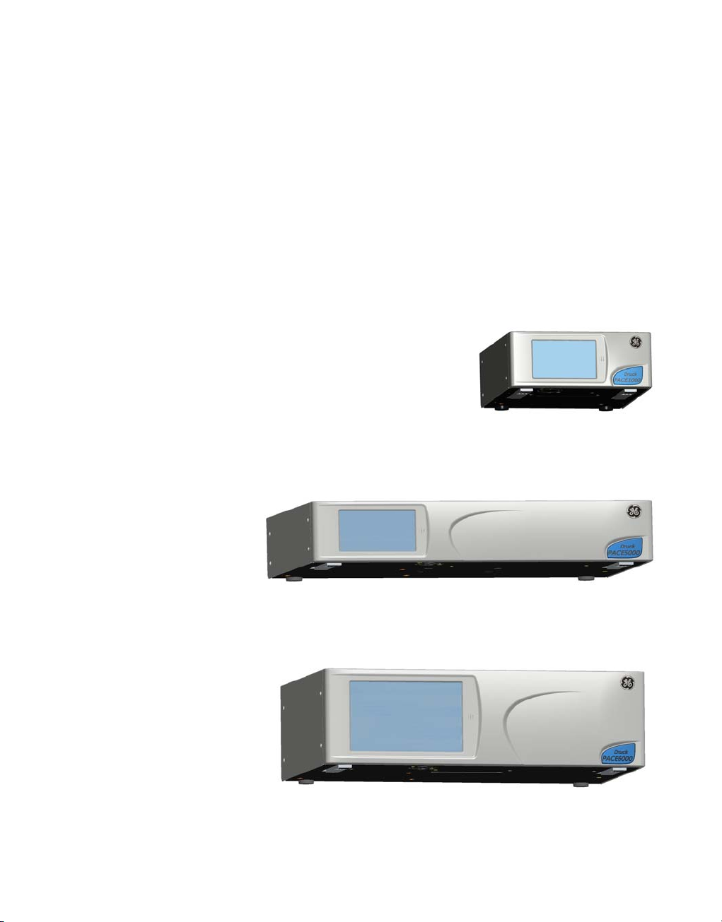
PACE1000
PACE5000
PACE6000
Page 2

© 2015 General Electric Company. All Rights Reserved. Specifications are subject to change without
notice. GE is a registered trademark of General Electric Company. Other company or product names
mentioned in this document may be trademarks or registered trademarks of their respective companies,
which are not affiliated with GE.
Page 3

Introduction
This technical manual provides SCPI protocol instructions for the remote control of the
PACE Series indicators and controllers.
Safety
The manufacturer has designed this product to be safe when operated using the
procedures detailed in this manual. Do not use this product for any other purpose than
that stated.
This publication contains operating and safety instructions that must be followed to
make sure of safe operation and to maintain the equipment in a safe condition. The
safety instructions are either warnings or cautions issued to protect the user and the
equipment from injury or damage.
Use qualified* programming technicians and good engineering practice for all
procedures in this publication.
Pressure
Do not apply pressure greater the maximum safe working pressure to the PACE Series.
Maintenance
The PACE Series must be maintained using the manufacturer’s procedures and should be
carried out by authorised service agents or the manufacturer’s service departments.
Technical Advice
For technical advice contact the manufacturer or subsidiary.
* A programming technician must have the necessary specialist knowledge of
programming, technical knowledge and documentation to carry out the required work
on the PACE Series.
Associated Documents:
A beginners Guide To SCPI by Barry Eppler, Published by Addison-Wesley Publishing
Company Inc. for Hewlett Packard (ISBN 0-201-56350-9)
This issue of the manual
This manual details the SCPI commands and queries for the PACE1000, PACE5000 and
PACE6000 pressure instruments. This issue removes erroneous code and clarifies the
operation status group (3.3).
K0472 Revision A i
Page 4

Table of Contents
Preliminary pages
Introduction .................................................................................................................................i
Safety .................................................................................................................................i
Table of contents (this table)..........................................................................................................................ii
List of Illustrations .................................................................................................................................vi
List of Tables .................................................................................................................................vii
Abbreviations .................................................................................................................................vii
Pressure measurement units......................................................................................................................... viii
Code Definitions ................................................................................................................................. vii
Pressure unit conversions...............................................................................................................................viii
Section page
1 INTRODUCTION ............................................................................................................1-1
1.1 General ...................................................................................................................................1-1
1.2 Remote/Local Operation . .............................................................................................................................1-1
2 COMMAND STRUCTURE ................................................................................................2-1
2.1 Notation ...................................................................................................................................2-1
2.2 Message Terminators.............................................................................................................................2-1
2.3 Program headers ................................................................................................................................... 2-3
2.4 SCPI data types ................................................................................................................................... 2-4
3 STATUS SYSTEM ............................................................................................................ 3-1
3.1 Output queue ................................................................................................................................... 3-3
3.2 Standard event group................................................................................................................................. 3-4
3.3 Operation status group ............................................................................................................................ 3-5
3.4 Status byte group ....................................................................................................................................... 3-7
3.5 Instrument errors ....................................................................................................................................... 3-10
4 COMMAND and QUERY SUMMARY.................................................................................. 4-1
4.1 Command structure................................................................................................................................ 4-1
CALibration ...................................................................................................................................4-3
:CAL:PRES:POIN ................................................................................................................................... 4-3
:CAL:PRES:ACC ................................................................................................................................... 4-4
:CAL:PRES:ABOR ................................................................................................................................... 4-5
:CAL:PRES:VAL ...................................................................................................................................4-6
:CAL:PRES:ZERO:VALV..............................................................................................................................4-7
:CAL:PRES:ZERO:AUTO............................................................................................................................. 4-8
:CAL:PRES:ZERO:TIME .............................................................................................................................. 4-9
:CAL:PRES:ZERO:TIME:STAT.................................................................................................................... 4-10
ii K0472 Revision A
Page 5

DISPlay ................................................................................................................................. 4-11
DISP:WINDow ................................................................................................................................. 4-11
INPut .................................................................................................................................4-12
INP:LOG .................................................................................................................................4-12
INP:LOG:STAT .................................................................................................................................4-13
INSTrument .................................................................................................................................4-14
:INST:CAT:ALL ................................................................................................................................. 4-14
:INST:CONT:SENS ................................................................................................................................. 4-15
:INST:DISP .................................................................................................................................4-16
:INST:LIM .................................................................................................................................4-17
:INST:MAC .................................................................................................................................4-19
:INST:SENS .................................................................................................................................4-20
:INST:SENS:CALD ................................................................................................................................. 4-21
:INST:SENS:FULL ................................................................................................................................. 4-22
:INST:SENS:NEG .................................................................................................................................4-23
:INST:SENS:READ ................................................................................................................................. 4-24
:INST:SENS:SN .................................................................................................................................4-25
:INST:SENS:ZERO .................................................................................................................................4-26
:INST:SN .................................................................................................................................4-27
:INST:TASK .................................................................................................................................4-28
:INST:TASK:AERO .................................................................................................................................4-29
:INST:UNIT ................................................................................................................................. 4-30
:INST:VERS ................................................................................................................................. 4-31
OUTPut .................................................................................................................................4-32
:OUTP:STAT .................................................................................................................................4-33
:OUTP:LOG .................................................................................................................................4-34
:OUTP:ISOL:STAT .................................................................................................................................4-35
SENSe .................................................................................................................................4-36
SENS:ALT .................................................................................................................................4-36
SENS:ALT:INL ................................................................................................................................. 4-37
SENS:ALT:INL:TIME ................................................................................................................................. 4-38
SENS:ALT:RANG .................................................................................................................................4-39
SENS:ALT:SLEW .................................................................................................................................4-40
SENS:AIRF:QFE .................................................................................................................................4-41
SENS:AIRF:QFF .................................................................................................................................4-42
SENS:AIRF:QNH .................................................................................................................................4-43
SENS:MACH .................................................................................................................................4-44
SENS:MACH:INL ................................................................................................................................. 4-45
K0472 Revision A iii
Page 6

SENS:MACH:INL:TIME ............................................................................................................................4-46
SENS:MACH:RANG ................................................................................................................................. 4-47
SENS:MACH:SLEW ................................................................................................................................. 4-48
:SENS:PRES ................................................................................................................................. 4-49
:SENS:PRES:AVER ................................................................................................................................. 4-50
:SENS:PRES:AVER:RES............................................................................................................................ 4-51
:SENS:PRES:AVER:TIME.......................................................................................................................... 4-52
:SENS:PRES:INL .................................................................................................................................4-53
:SENS:PRES:INL:TIME.............................................................................................................................. 4-54
:SENS:PRES:SLEW .................................................................................................................................4-55
:SENS:PRES:BAR ................................................................................................................................. 4-56
:SENS:PRES:RANG .................................................................................................................................4-57
:SENS:PRES:RES ................................................................................................................................. 4-58
:SENS:PRES:CORR:HEAD....................................................................................................................... 4-59
:SENS:PRES:CORR:HEAD:STAT............................................................................................................ 4-60
:SENS:PRES:CORR:HEAD:OFFS...........................................................................................................4-61
:SENS:PRES:CORR:HEAD:OFFS:STAT................................................................................................4-62
:SENS:PRES:CORR:VOL ..........................................................................................................................4-63
:SENS:PRES:FILT:LPAS:BAND...............................................................................................................4-64
:SENS:PRES:FILT:LPAS:FREQ................................................................................................................ 4-65
:SENS:PRES:FILT:LPAS:STAT.................................................................................................................. 4-66
:SENS:PRES:MAX ................................................................................................................................. 4-67
:SENS:PRES:MAX:RES .............................................................................................................................4-68
:SENS:PRES:MIN .................................................................................................................................4-69
:SENS:PRES:MIN:RES ..............................................................................................................................4-70
:SENS:PRES:PERC ................................................................................................................................. 4-71
:SENS:PRES:PERC:SPAN ........................................................................................................................4-72
:SENS:PRES:PERC:STAT.......................................................................................................................... 4-73
SENS:SPE .................................................................................................................................4-74
SENS:SPE:INL .................................................................................................................................4-75
SENS:SPE:INL:TIME ................................................................................................................................. 4-76
SENS:SPE:RANG ................................................................................................................................. 4-77
SENS:SPE:SLEW ................................................................................................................................. 4-78
SOURce ................................................................................................................................. 4-79
SOUR:ALT ................................................................................................................................. 4-79
SOUR:MACH:REF ................................................................................................................................. 4-80
SOUR:MACH:REF:MODE........................................................................................................................ 4-81
SOUR:MACH:REF:VAL.............................................................................................................................4-82
iv K0472 Revision A
Page 7

SOUR:MACH:LEV:IMM:AMPL...............................................................................................................4-83
:SOUR:PRES:COMP ................................................................................................................................. 4-84
:SOUR:PRES:EFF .................................................................................................................................4-85
:SOUR:PRES:INL .................................................................................................................................4-86
:SOUR:PRES:INL:TIME.............................................................................................................................4-87
:SOUR:PRES:LEV:IMM:AMPL ................................................................................................................4-88
:SOUR:PRES:LEV:IMM::VENT ................................................................................................................ 4-89
:SOUR:PRES:RANG .................................................................................................................................4-91
:SOUR:PRES:RANG:LOW ....................................................................................................................... 4-92
:SOUR:PRES:SLEW .................................................................................................................................4-93
:SOUR:PRES:SLEW:MODE.....................................................................................................................4-94
:SOUR:PRES:SLEW:OVER .......................................................................................................................... 4-95
SOUR:MACH:LEV:IMM:AMPL...............................................................................................................4-96
SOUR:MACH:LEV:IMM:AMPL:SLEW .................................................................................................. 4-97
STATus ................................................................................................................................. 4-98
:STAT:OPER:COND ................................................................................................................................. 4-98
:STAT:OPER:ENAB .................................................................................................................................4-99
:STAT:OPER:EVEN .................................................................................................................................4-100
:STAT:OPER:PRES:COND........................................................................................................................ 4-101
:STAT:OPER:PRES:ENAB.........................................................................................................................4-102
:STAT:OPER:PRES:EVEN .........................................................................................................................4-103
:STAT:PRES ................................................................................................................................. 4-105
:STAT:QUES:COND .................................................................................................................................4-106
:STAT:QUES:ENAB ................................................................................................................................. 4-107
:STAT:QUES:EVEN ................................................................................................................................. 4-108
SYSTem ................................................................................................................................. 4-109
SYST:COMM:USB ................................................................................................................................. 4-109
:SYST:ERR .................................................................................................................................4-110
:SYST:DATE .................................................................................................................................4-112
:SYST:SET ................................................................................................................................. 4-113
:SYST:TIME .................................................................................................................................4-114
:SYST:COMM:SER:CONT:RTS ............................................................................................................... 4-115
:SYST:COMM:SER:CONT:XONX ........................................................................................................... 4-116
:SYST:COMM:SER:BAUD........................................................................................................................ 4-117
:SYST:COMM:SER:TYPE:PAR................................................................................................................. 4-118
:SYST:COMM:GPIB:SELF:ADDR ........................................................................................................... 4-119
:SYST:AREA ................................................................................................................................. 4-120
:SYST:PASS:CDIS ................................................................................................................................. 4-121
:SYST:PASS:CEN .................................................................................................................................4-122
K0472 Revision A v
Page 8

:SYST:PASS:CEN:STAT............................................................................................................................. 4-123
:SYST:VERS .................................................................................................................................4-124
UNIT .................................................................................................................................4-125
UNIT:ALT ................................................................................................................................. 4-125
UNIT:CONV .................................................................................................................................4-126
:UNIT:PRES .................................................................................................................................4-127
UNIT:PRES:DEF ................................................................................................................................. 4-128
:UNIT:SPE ................................................................................................................................. 4-130
4.2 * Common SCPI commands - three letter commands, prefixed by * ...........................4-131
*CLS .................................................................................................................................4-131
*ESE .................................................................................................................................4-132
*ESR ................................................................................................................................. 4-133
*IDN? .................................................................................................................................4-134
*OPC .................................................................................................................................4-135
*SRE ................................................................................................................................. 4-136
*STB? .................................................................................................................................4-137
*TST? ................................................................................................................................. 4-138
*WAI ................................................................................................................................. 4-139
4.3 Instrument control commands - three letter commands, prefixed by : ......................4-140
:GTL .................................................................................................................................4-140
:LLO ................................................................................................................................. 4-141
:LOC .................................................................................................................................4-142
:REM ................................................................................................................................. 4-143
:SRQ ................................................................................................................................. 4-144
:SRQ:ENAB ................................................................................................................................. 4-145
:SYN ................................................................................................................................. 4-146
5 ERRORS .......................................................................................................... 5-1
List of Illustrations
Figure page
Figure 1-1 System Model..................................................................................................................................... 1-1
Figure 3-1 Status System .................................................................................................................................... 3-2
List of Tables
Table page
3-1 Standard Event Register ............................................................................................................................. 3-4
3-2 Operation Status Register..........................................................................................................................3-6
3-3 Status Byte Register......................................................................................................................................3-8
5-1 Errors -100 to -199 .......................................................................................................................................5-1
5-2 Errors -200 to -299 .......................................................................................................................................5-2
5-3 Errors -300 to -400 .......................................................................................................................................5-2
vi K0472 Revision A
Page 9

5-3 Errors +201 to +212 ......................................................................................................................................5-2
Abbreviations
The following abbreviations are used in this manual; abbreviations are the same in the singular and plural.
aAbsolute mVmillivolts
ALT Altitude MWP Maximum working pressure
ASCII American Standard Code for Information Interchange No Number
CAS Calibrated airspeed PACE
e.g. For example PDCR Pressure transducer
Fig. Figure PED Pressure equipment directive
ft Foot PTX Pressure transmitter
g Gauge ROC Rate of climb
GPIB General purpose interface bus RS232 Serial communications standard
IDOS Intelligent digital output sensor (GE product) Rt CAS Rate of Calibrated airspeed
i.e. That is Rt MACH Rate of MACH
IEEE 488
kg kilogram SCPI
kts knots SDS Sales data sheet
m Metre Tx Transmit data
mA milliampere UUT Unit under test
max Maximum +ve Positive
mbar Millibar -ve Negative
min Minute or minimum °C Degrees Celsius
mm millimetre °F Degrees Fahrenheit
Institute of Electrical and Electronic Engineers standard
488 (for programmable devices with a digital interface)
Rx Receive data
Pressure automated calibration
equipment
Standard commands for
programmable instruments
Pressure measurement units
The following units are used in this manual
ATM
BAR
CMH2O
CMHG
FTH2O
FTH2O4
HPA
INH2O
INH2O4
INH2O60
INHG
KG/CM2
K0472 Revision A vii
atmosphere
bar
centimetres of water at 20°C
centimetres of mercury
feet of water at 20°C
feet of water at 4°C
hecto Pascals
inches of water at 20°C
inches of water at 4°C
inches of water at 60°F
inches of mercury
kilogrammes per square centimetre
KG/M2
KPA
LB/FT2
MH2O
MHG
MMH2O
MMHG
MPA
PA
PSI
TORR
MBAR
kilogrammes per square metre
kilo Pascals
pounds per square foot
metres of water
metres of mercury
millimetres of water
millimetres of mercury
mega Pascals
Pascals
pounds per square inch
torr
millibar
Page 10

Code Definitions
The following codes are used in this manual.
ABOR Abort LIM Limit
ADDR Address LLO Local lock out
AVER Average LOG Logical
ALT Altitude LPAS Low pass (filter)
AMPL Amplitude MAV Message available in output queue
ATOD Analog to Digital MEAS Measure
BAR Barometer MSS Summary bit after SRQ
BRID Bridge NEGC Negative Calibration
CAL Calibration OFFS Offset
CAT Catalogue OPC Operational condition
CDIS Cdisable (calibration disable) OPER Operation
CEN Cenable (calibration enable) OPT Option
CLS Clear OSB Summary bit from standard operations status register
COMM Communicate OVER Overshoot
COMP Compensate OUTP Output
COND Condition PAR Parity
CONF Configuration PASS Password
CONT Controller PERC Percent
CONV Convert POIN Points
CORR Correction PRES Preset
COUN Count PRES Pressure
DEF Define QUE Queue
DIAG Diagnostic QUES Questionable
DIOD Diode RANG Range
DISP Display REF Reference
EAV Error in error queue RES Resolution
EFF Effort RES RESet
ENAB Enable SAMP Sample
EOI End of input SENS Sense
ERR Error SEPT Set-point
ESB Summary bit from standard event SER Serial
ESE Event status enable SOUR Source
ESR Event status register SPE Speed
EVEN Event SRE Service request enable
FILT Filter SRQ Service request
FREQ Frequency STAR Start
FULL Fullscale STB Status register query
GTL Go to local STAT State
HEAD Head SYST System
IDN Identification TIM Time to set-point
IMM Immediate UNIT Unit of pressure
INL In limit VAL Value
INP Input VALV Valve
INST Instrument VERS Version
ISOL Isolation VOL Volume
LEV Level
viii K0472 Revision A
Page 11
PACE Series SCPI Manual
Pressure
out
logic
logic
Pressure
in
SOURce
sub-system
UNITs
sub-system
CALibrate
sub-system
INPut
sub-system
SENSe
sub-system
INSTrument
sub-system
OUTPut
sub-system
SYSTem
sub-system
S TATu s
sub-system
1INTRODUCTION
1.1 General
The IEEE 488 and RS232 interfaces of the PACE Series provide remote control of the
instrument from a suitable computer or controller. The SCPI protocol enables any instrument
with a SCPI facility to be controlled using the same commands. The PACE Series use the full
SCPI command set and the defined SCPI syntax.
The following sections describe and define each instrument command used by the PACE
Series. The commands for the aeronautical option and the sensor calibration module option
are described and defined in separate sections. Each section contains a quick reference
structure of the relevant commands.
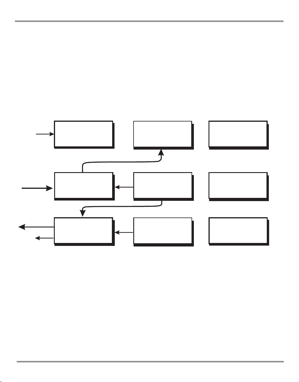
Figure 1-1 System Model
System Model
SCPI starts with a high-level block diagram of the measurement functions of the instrument.
Each functional block is broken down into smaller block diagrams. SCPI contains a hierarchy
of commands called a subsystem that maps directly to the hierarchy of the block diagram.
1.2 Remote/Local Operation
Most commands received over the SCPI interface automatically puts the PACE Series into
remote control mode and disables the front panel touch-screen. Sending the LOC command
returns the PACE Series to local control mode and enables the front panel touch-screen .
K0472 Revision A 1-1
Page 12

1 Description
intentionally left blank
K0472 Revision A 1-2
Page 13

PACE Series SCPI Manual
root Level 1 Level 2
AB
C
D
E
F
G
H
J
2 COMMAND STRUCTURE
This section describes the structure of the commands and data sent and received by a PACE
Series Controller/Calibrator.
2.1 Notation
All SCPI commands are based on a hierarchical tree structure consisting of key words and
parameters. Associated commands are grouped together under a common node in the
hierachy.
In the command tree the command A is the root command. A tree pointer is used to decode
the SCPI commands. At power-up the pointer goes to the root command.
2.2 Message Terminators
All SCPI commands are terminated by line feed i.e., either <newline> (ASCII character,
decimal 10), EOI for IEEE. After receiving a termination character the tree pointer returns to
the root command.
Colon
A colon moves the current path down one level in the command tree, (e.g., the colon in
SOURCE:PRESSURE specifies PRESSURE the is one level below SOURCE). When the colon is
the first character of the command, it specifies that the next command is a root level
command (e.g., :SOURCE specifies that SOURCE is a root level command).
Semicolon
A semicolon separates two commands in the same message without changing the tree
pointer.
(e.g., with reference to the tree):A:B:E;F;G
This equivalent to sending three messages:
:A:B:E
:A:B:F
:A:B:G
K0472 Revision A 2-1
Page 14

2 Command Structure
Commas
If a command requires more than one parameter, separate adjacent parameters by using a
comma. A comma does not affect the tree pointer.
(e.g.) :SYSTEM:TIME 10,25,30
To execute a command the full path to the command must be specified:
(e.g.) :OUTPut:STATe ON
This turns the pressure controller on.
Note:
There must be a space between the command words and the parameter. In the above
example there is a space between :STATe and ON.
SCPI commands are not case sensitive and may have a short form.
(e.g.) :OUTP is the short form of OUTPUT.
Some nodes can be the default node and these key words are optional when programming
the command. The instrument processes the command, with the same effect, with or
without the option node. In this manual [] enclose [default notes].
(e.g.) :SOURce[:PRESsure:][:LEVel][:IMMediate][:AMPlitude] 5.0
can be sent as
:SOURce:PRESsure:LEVel 5.0
or
:SOURce 5.0
This sets the set-point to 5.0
K0472 Revision A 2-2
Page 15

PACE Series SCPI Manual
2.3 Program Headers
Program headers are keywords that identify a command, instruments accept both upper
and lower case characters in a program header. There are two types of program header,
common command headers and instrument control headers; each header can be a
command or a query.
Common Command and Query Headers
The common command and query program header syntax, specified in IEEE 488.2, are
defined as follows:
Command
*<PROGRAM MNEMONIC>
Query
*<PROGRAM MNEMONIC>?
Instrument Control Command and Query Headers
The instrument control command and query program header syntax controls and extracts
data from the instrument as follows:
Command
:<MNEMONIC>
:<MNEMONIC> <PARAMETER>
Query
:<MNEMONIC>?
Instrument command headers can have a numeric suffix to identify each of several cases of
the same header; the numeric suffix applies to both the long and short forms. All commands
headers without a numeric suffix assume the value 1.
e.g.,
:OUTPut:LOGic1?
is the same as
:OUTPut:LOGic:?
Queries
A query is a program header with an attached question mark character (?). On receiving a
query, the current settings are loaded in the output buffer. A query does not affect the
operation or set-up of the instrument.
When the parameter of a command contains enumerated character data, both long form
and short form are recognised. A query causes the return of data in the short form.
Querying numeric parameters causes the resulting data to be returned in the units selected
by the instrument unless specified otherwise.
K0472 Revision A 2-3
Page 16

2 Command Structure
2.4 SCPI Data Types
A variety of data types can be sent to the instrument as parameters or sent out from the
instrument as response data.
Decimal Data
All normal decimal expressions are accepted including optional signs, decimal point and
scientific notation.
Note:
This includes floating point data.
The following are valid:
123
45.67
-2.6
4.6e-10
.76
A suffix multiplier can be added to the numeric value.
:SOUR 100 m
would set the programmable output to 0.1 units (100m units).
The multipliers supported are:
Mnemonic Multiplier
A1e-18
G1e+9
K1e+3
M1e-3
T 1e+12
If a real value is sent to the instrument when an integer is expected, it will be rounded to an
integer.
Integer Data
Integer data are whole numbers (containing no decimal places). A query of an integer value
returns numbers containing no decimal places.
Note:
Integer values can be specified in binary, octal or hexadecimal formats using the suffix letters
(upper or lower case) B, Q and H respectively.
e.g., #B1010 binary representation of 10
#Q71 octal representation of 57
#HFA hexadecimal representation of 250
Hexadecimal digits A-F can be in upper or lower case.
K0472 Revision A 2-4
Page 17

PACE Series SCPI Manual
Enumerated Character Data
Enumerated characters are used for data that has a finite number of values; enumerated
parameters use mnemonics to represent each valid setting.
The mnemonics have long and short forms just like command mnemonics.
Example:
:SOURce:PRESsure:SLEW:MODE MAXimum
selects the maximum rate mode.
A query of an enumerated parameter always returns the short form data in upper case.
Example:
:SOURce:PRESsure:SLEW:MODE?
queries rate mode, reply:
:SOUR:PRES:SLEW:MODE MAX
Boolean Data
Boolean data can only be one of two conditions; the numbers 1 and 0. Boolean can be “on”
or “off”, queries return 1 or 0.
Example:
:OUTPut:STATe 1
A query of boolean data always returns 1 or 0.
String Data
String data can contain any of the ASCII characters. A string must start with a double
"quote" (ASCII 34) or a single `quote` (ASCII 39) and end with the same
Note:
Characters in a string in either double "quote" or single `quote` are case sensitive.
Example: 1
:SOURCe[:PRESsure]:RANGe ‘2.00barg’
Example: 2
:SOURCe[:PRESsure]:RANGe “2.00barg”
selects the 2 bar g range.
A query of a string parameter always returns the string in double "quotes".
character.
K0472 Revision A 2-5
Page 18

2 Command Structure
Intentionally left blank
K0472 Revision A 2-6
Page 19

PACE Series SCPI Manual
3 STATUS SYSTEM
The status reporting system informs the external controller that an event has occurred. This
information is in the form of a service request (SRQ) using IEEE 488 or an SRQ message using
RS232.
The PACE Series uses status reporting as defined in IEEE 488.2 with the implementation of
status registers.
The OPERation status registers have been implemented to comply with the SCPI protocol.
These are registers where the individual bits are summary bits of the status of the
instrument. Since the SCPI protocol does not include pressure instruments, bit 10 of both
these registers are used as a pressure summary bit. This pressure summary bit is expanded
to two, 16 bit registers (Bit 15 is not used and is always zero).
The only bit implemented in the Operation status register is bit 10 (summary of the pressure
operation status).
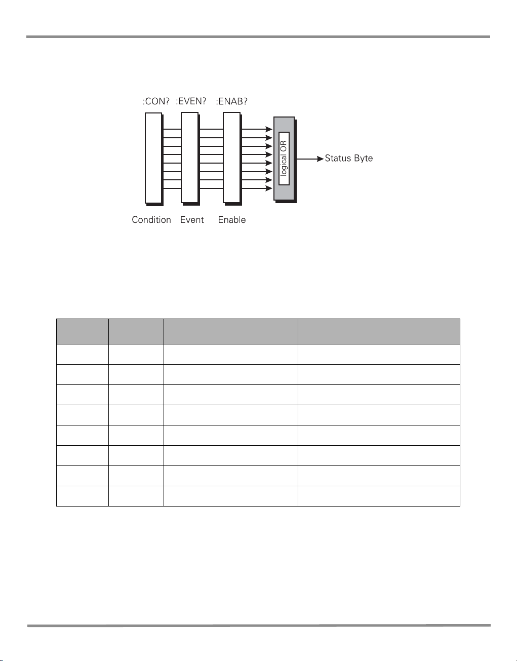
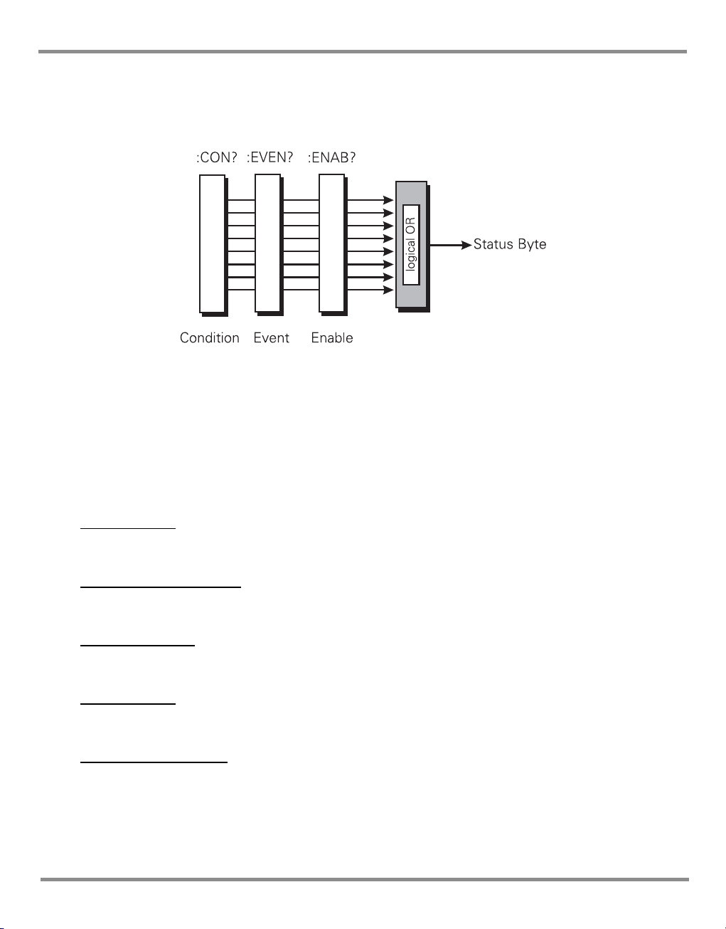
A summary bit is the final output of a data structure, it is a single bit that shows the status of
one or more related events in the instrument. The basic structure of a summary bit
• Condition register
•Event register
• Enable register
• Logical ANDing of the Event and Enable registers
• Summary bit that summarises the result using OR logic
Condition Register
This register shows the current status of the device. The condition register is constantly
updated - the bits in the register are set or reset showing the current condition.
Event Register
The event register shows an event that occurs in the condition register (a condition bit goes
from low to high). This condition change is stored and only reset when the event register is
read or the *CLS command sent.
Enable Register
This register allows the results of the event register to pass through to the next cascaded
register and enables the user to select the event that should generate the final SRQ event.
K0472 Revision A 3 - 1
Page 20
3 Status System
logical OR
MAV
ESB
OSB
MSS
MAV
ESB
OSB
Status Byte
EN 8 bitEV
*SRE
STAT:OPER
:ENAB
*STB?
SERIAL POLL
STAT:OPER
:PRES:ENAB 511
Pressure Operations 15 bit
STAT
:OPER
:EVENT?
STAT:OPER
:PRES:ENAB?
Operation Status 16 bit
logical OR
CEV EN
logical OR
C
EVEN
Output Queue
Message
Message
Message
Message
SYST:ERR?
*SRE
Error Queue
Error Message
Error Message
Error Message
Error Message
Error Message
logical OR
QYE
CME
EXE
QYE
CME
EXE
Standard Event
EV EN 8 bit
*ESR? *ESE
MSS
EAV
EAV
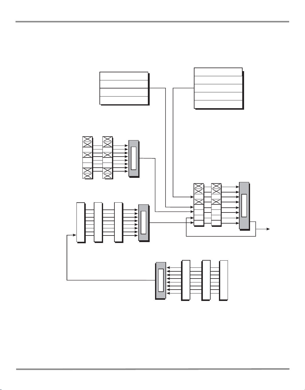
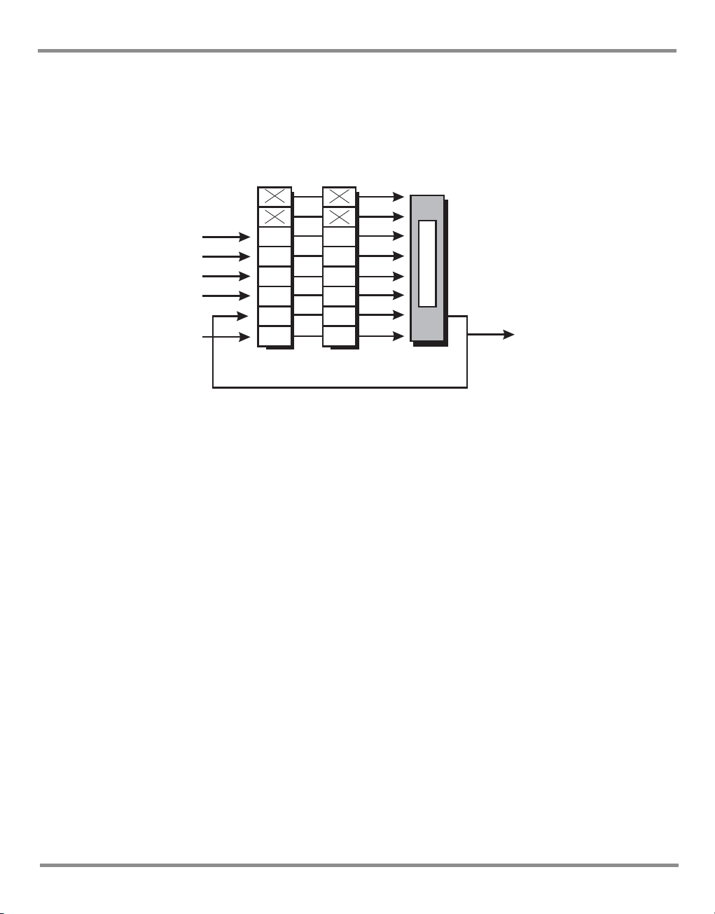
The status system implemented in the instrument is shown in the following diagram:
Note:
Initial values of registers are 0, with the queues empty.
Key:
C = Condition - variable values
EV = Latched values
EN = Bit mask
K0472 Revision A 3 - 2
Figure 3-1 Status System
Page 21

PACE Series SCPI Manual
3.1 Output queue
The output queue is a text readable data queue that is read through the IEEE 488 talk
command. The queue is cleared by reading all elements in it or by the *CLS command.
Every time a query has been successfully completed, the response, in a text readable format
is placed at the end of the output queue. If the MAV bit in the "Status Byte" was previously
cleared it will be set. The output queue can contain up to 256 characters. If there is not
enough space in the output queue for a new message, the error -350, "Queue overflow" will
be placed into the error queue and the most recent output message will be lost.
K0472 Revision A 3 - 3
Page 22
3 Status System
3.2 Standard event group
The standard event group are 8 bit registers that are read by the IEEE 488 standard
commands. The event register is cleared by reading it; the event and enable registers are
cleared by the *CLS command.
Bits within the standard event condition register are set by system errors and events. In
addition to setting the status bits, a text message will be placed in the error queue. The ESB
bit in the status byte sets if the associated bit in the event enable register is set. The enable
register may be set through the *ESE command so that selected standard events cause the
ESB bit to be set. The system events that set each bit are as follows:
Bit Name Description Meaning/data
0 OPC Not used Reserved currently returns 0
1 RQC Not used Reserved currently returns 0
2 QYE -400 to -499 Query errors
3 DDE Not used Reserved currently returns 0
4 EXE -200 to -299 Execution errors
5 CME -100 to -199 Command errors
6 URQ Not used Reserved currently returns 0
7 PON Not used Reserved currently returns 0
Table 3-1 Standard Event Register
K0472 Revision A 3 - 4
Page 23
PACE Series SCPI Manual
3.3 Operation status group
The operation status group are 16 bit registers that are read by the STAT:OPER:PRES
commands. The event register is cleared by reading it; the event and enable registers are
cleared by the *CLS command.
When a standard operation condition occurs an appropriate bit is set in the condition register
(this clears when the condition no longer exists). The bit is then latched in the event register. If
the associated bit in the enable register is set, the OPR bit in the status byte sets. The enable
register may be set through the STAT:OPER:PRES:ENAB command so that only selected standard
operation events cause the OPR bit to set.
Problems can occur with some IEEE 488 controllers reading 16 bit unsigned numbers. All
registers in this group do not use bit 15. The enable bit cannot be set and when read returns 0.
The condition register is defined as follows:
Vent complete
This signal occurs when the controller has been requested to vent and the vent has
completed or timed out.
Range change complete
This signal occurs when the controller has been requested to perform a range change and
the range change is complete.
In-Limits reached
This signal is set every time the controlled pressure is within the specified limits. The signal is
only generated if the pressure has been within limits for a user defined wait time period.
Zero complete
This signal is generated when a manual or timed zero is complete. If the zero times out then
this signal is also generated.
Range compare alarm
This signal is generated when the range compare alarm is triggered during the range
compare process.
(PACE1000 only)
K0472 Revision A 3 - 5
Page 24

3 Status System
Bit
(1)
0 Vent complete 1 Range change complete
2 In-limits reached 3 Zero complete
4 Auto-zero started 5 Fill time, timed-out
6 Reserved - returns 0 7 Range compare alarm
8 Switch contacts changed state 9 Reserved - returns 0
10 Reserved - returns 0 11 Reserved - returns 0
12 Reserved - returns 0 13 Reserved - returns 0
14 Reserved - returns 0 15 Reserved - returns 0
Data
(2)
Bit
(3)
Data
(4)
Table 3-2 Operation Status Register
Auto zero started
When the controller is in the auto zero mode this signal indicates that the auto zero process
has started. The zero complete signal indicates that the zero process has finished.
Fill timed out
If a set-point has been requested and the set-point cannot be achieved within the fill timeout
time, the fill timed out signal is generated.
Switch contacts changed state
Every time the switch contacts used for performing a switch test change state this bit is set.
K0472 Revision A 3 - 6
Page 25
PACE Series SCPI Manual
logical OR
*STB?
*SRE?
Event Enable
SERIAL POLL
ESB
MSS
OSB
MAV
QUE
ESB
OSB
MAV
QUE
Standard event
Standard
operation
Output queue
Question data
EAV EAV
Error queue
MSS
3.4 Status Byte group
The status byte group are 8 bit registers that are read by the IEEE 488 standard commands.
The event register is cleared by reading it; the event and enable registers are cleared by the
*CLS command.
Bits within the status byte are a summary of other data structures in the status system.
These bits will become set if other parts of the status system indicates that they should do so
(i.e., a message in the output queue or error queue or, a condition and enable set in a register
pair).
If the associated bit in the status enable register is set, a serial poll is generated and bit 6 is
set. The enable register may be set through the *SRE command so that only selected status
bits cause a serial poll.
Note: Bit 6 of the enable register is always set to 0.
There are some small differences between * STB? and serial polling. Either method can be
used to read the state of bits 0-5 and bit 7. The reading method is different for bit 6 when
using *STB? and serial poll. In general, use serial polling inside interrupt service routines, not
*STB?
Bit 2 - EAV sets when there is an error in the error queue. The :SYST:ERR? command has to be sent
to retrieve the error. The error queue buffers a maximum of five errors. When no more
errors are available the message “No Error” is returned.
Bit 4 - MAV sets when there is a message available in the output queue.
K0472 Revision A 3 - 7
Page 26

3 Status System
Bit 5 - ESB sets when a standard event has occurred in the Standard Event Register.
Bit 6 - MSS sets when an SRQ is generated - SRQ sets when both the Status byte and the Service
Request Enable register are at logic 1 (AND function).
RS232 Specific
A service request (SRQ) produces the message::SRQ <value>
where:
<value> = the contents of the status summary byte.
The status system data structure sets each bit as follows:
Bit Name Description
0 - Reserved currently returns 0
1 - Reserved currently returns 0
2 EAV Error in errror queque
3 - Reserved currently returns 0
4 MAV Messages available in output queque
5 ESB Summary bit from standard event
6 MSS Summary bit after service request - SRQ
7 OSB Summary bit from standard operations status
Table 3-3 Status Byte Register
Example commands using the Status Byte and Status Byte Enable registers:
*SRE 16 Generate an SRQ interrupt when messages are available.
*SRE? Find out what events are enabled to generate SRQ interrupts.
*STB? Read and clear the Status Byte Enable register.
IEEE 488 Specific
Bit 7 - OSB sets when the pressure operations register bit 10 changes state. The operations
register is a 16 bit register only using bit 10. This bit is a summary of the pressure operations
register.
K0472 Revision A 3 - 8
Page 27

PACE Series SCPI Manual
Status reporting register structure
To set-up the status reporting system.
1 All status registers should be cleared by the command:
*CLS
2 The Pressure Operations Event register has to be set to enable the Pressure Operations
Condition Register to send all the events to be reported; use the command:
:STAT:OPER:PRES:ENAB 511
The enabled events may also be read by the query:
:STAT:OPER:PRES:ENAB?
3 The Operation Status Event register must then be enabled to read bit 10 by the
command:
:STAT:OPER:ENAB 1024
The enabled events may also be read by the query:
:STAT:OPER:ENAB?
4 The status request to enable the SRQ must then be set.
To enable only the Operation Status register (OSB) send the command:
*SRE 128
To enable the Operation Status register (OSB) and the Error Queue (EAV) send the
command:
*SRE 132
This register may also be read by the query:
*SRE?
An event occurring generates an SRQ, the Status Byte should be queried to find the
source of the event.
K0472 Revision A 3 - 9
Page 28

3 Status System
If bit 2 of the Status Byte Register is set the error queue can be read by the query:
:SYST:ERR?
Keep issuing this query until there are no more errors in the error queue. At this point,
bit 2 of the Status Byte Register clears.
If bit 7 of the Status Byte Register is set the Pressure Operations event register can be
read by the query:
:STAT:OPER:PRES?
returning the bits of events that have occurred. Reading this register clears it and the
associated status bit (bit 7).
At any time the instantaneous status of the pressure system can be read by the query:
:STAT:OPER:PRES:COND?
3.5 Instrument Errors
Any instrument error that occurs, either programming errors or execution errors, is stored in
an error queue which is separate from the main output queue. The errors can be read by
issuing the following command query:
:SYST:ERR?
The error queue can hold up to five errors. Each time the error queue is queried the
instrument responds with the next stored error in the queue. The response consists of an
error number followed by a string describing the error. When the error queue is empty the
instrument responds with:
:SYST:ERR 0, No error
Querying the error queue clears the storage location in the error buffer. If more than five
errors occur, before being queried, the ‘Queue overflow;Error queue overflow’ message is
placed into the error queue. All subsequent errors are lost until the error queue is cleared.
K0472 Revision A 3 - 10
Page 29

PACE Series SCPI Manual
4 COMMAND AND QUERY SUMMARY
The following lists of all the SCPI commands and queries that apply to the instrument.
4.1 Command Structure
Some of the commands in the following summary are enabled at specific times and
conditions, most can be enabled at any time. The command structure divides into
subsystems as follows:
Command sub-system
:CALibration - calibration commands.
:DIAGnostic - instrument generated condition data.
INPut - switch input of the control module.
:INSTrument - instrument specific commands.
:OUTPut - controls the output pressure and logical outputs.
:SENSe - directs the instrument to measure selected parameters.
:SOURce - the commands that control the pressure outputs.
:STATus - instrument state.
:SYSTem - errors and SCPI version.
:UNIT - sets the units for the instrument.
Common SCPI commands - three letter commands, prefixed by *.
Instrument control commands - three letter commands, prefixed by :.
K0472 Revision A 4-1
Page 30

4 Command and Query Summary
Command and Query Details
This section describes each command in detail including parameters passed to it and
response data returned. The general short form command is shown at the top of each page.
The following information is then given:
Applicability - A list of instruments that accepts and responds to the
command or query.
Command Syntax - The upper case represents the short form command.
Parameter - Type: DECIMAL, INTEGER, ENUMERATED CHARACTER,
BOOLEAN or STRING.
Short form - The short alternative for the command to be effective.
Function - Basic function of the command.
Default - The default value or the maximum and minimum values
where appropriate.
Query Syntax - The upper case represents the short form query command.
Parameter - Type: DECIMAL, INTEGER, ENUMERATED CHARACTER,
BOOLEAN or STRING.
Short form - The short alternative for the query to be effective.
Function - Basic function of query command.
Response - Data returned by the instrument following the query
command.
Description
Details of the command and query with any conditions of use and any related commands.
Note:
Many of the command descriptions contain an example code: sent (Tx) to the instrument and
the data received (Rx) from the instrument.
Dual module instruments
Sending and receiving to a module must include either number 1 or 2 after the first part of
the command or query. Without the module number, a dual module instrument defaults to
module 1.
Example
K0472 Revision A 4-2
Long form
Tx> :SOURce2:PRESsure:EFFort?
Rx> :SOUR2:PRES:EFF -0.2342882
Short form
Tx> :SOUR2:PRES:EFF?
Rx> :SOUR2:PRES:EFF -0.2342882
Page 31

PACE Series SCPI Manual
CALibration
The CALibration subsystem enables the calibration of the transducers and the rate control
system, refer to the user manual for further details.
:CAL:PRES:POIN
Applicability: PACE1000, PACE5000, PACE6000
Command Syntax
n/a
Parameter:
Short form:
Function:
Defaults:
Query Syntax
:CALibration[x]:[PRESsure]:POINts?
where: x (module) = 1 or 2 (default - 1).
Short form: CAL:POIN?
Function: Gets the number of calibration points
Response: 3
Description
Valid only when calibration is enabled, this queries the number of calibration points.
Example
Tx> :CALibration2:PRESsure:POINts?
Rx> :CAL2:PRES:POIN 3
K0472 Revision A 4-3
Page 32

4 Command and Query Summary
:CAL:PRES:ACC
Applicability: PACE1000, PACE5000, PACE6000
Command Syntax
:CALibration[x]:[PRESsure]:ACCept
where: x (module) = 1 or 2 (default - 1)
Parameter: Integer 1
Short form: :CAL[x]:ACC
Function: Accepts calibration values
Defaults: no default value
Query Syntax
n/a
Short form:
Function:
Response:
Description
Valid only when calibration is enabled, this command accepts the calibration values entered
in the calibration process.
K0472 Revision A 4-4
Page 33

PACE Series SCPI Manual
:CAL:PRES:ABOR
Applicability: PACE1000, PACE5000, PACE6000
Command Syntax
:CALibration:[PRESsure]:ABORt
Parameter: None
Short form: :CAL[x]:ABOR
Function: Aborts calibration values
Defaults: no default value
Query Syntax
n/a
Short form:
Function:
Response:
Description
Aborts calibration.
K0472 Revision A 4-5
Page 34

4 Command and Query Summary
:CAL:PRES:VAL
Applicability: PACE1000, PACE5000, PACE6000
Command Syntax
:CALibration[x]:[PRESsure]:VALue[y]
where: x (module) = 1 or 2 (default - 1). y = 1, 2 or 3 (pressure point) (default - 1).
Parameter: <decimal>
Short form: :CAL[x]:VAL[y]
Function: Enables calibration value to be entered.
Defaults:
Query Syntax
:CALibration[x]:[PRESsure]:VALue[y]?
where: x (module) = 1 or 2 (default - 1). y = 1, 2 or 3 (pressure point) (default - 1).
Short form: :CAL[x]:VAL[y]?
Function: Queries calibration point y value of module x.
Response: Returns pressure value for VALue[y] of module [x].
Description
Valid only when calibration is enabled. This command enables a calibration value to be
entered during the calibration process. The query gets the calibration value.
y 3 Calibration points
1 lower pressure
2 middle pressure
3 higher pressure
Example for a 2 bar unit
Tx CAL:PRES:VAL1?
Rx CAL:PRES:VAL1 -0.9
Tx CAL:PRES:VAL2?
Rx CAL:PRES:VAL2 0
Tx CAL:PRES:VAL3?
Rx CAL:PRES:VAL3 2.0
K0472 Revision A 4-6
Page 35

PACE Series SCPI Manual
:CAL:PRES:ZERO:VALV
Caution: Opening the zero valve with high pressure in the system can cause damage to the
equipment. Reduce the system pressure and make sure the controller is OFF
before opening the zero valve.
Applicability: PACE5000, PACE6000
Command Syntax
:CALibration:[PRESsure]:ZERO:VALVe[STATe]
where: x (module) = 1 or 2 (default - 1)
Parameter: <boolean>
Short form: :CAL:ZERO:VALV
Function: Opens and closes zero valve.
Default: 0
Query Syntax
:CALibration:[PRESsure]:ZERO:VALVe[STATe]?
where: x (module) = 1 or 2 (default - 1)
Short form: CAL:ZERO:VALV?
Function: Queries state of valve.
Response: 1 - open
0- close
Description
This command is used to open and close the zero valve. The query gets the state of the zero
valve - open or close.
Example
TX> :CAL:PRES:ZERO:VALV 1
TX> :CAL:PRES:ZERO:VALV:STAT 1
Either of above two commands opens the zero valve.
TX> :CAL:PRES:ZERO:VALV: 0
TX> :CAL:PRES:ZERO:VALV:STAT 0
Either of above two commands close the zero valve,
switch OFF the controller.
Either: TX> :CAL:PRES:ZERO:VALV?
RX> :CAL:PRES:ZERO:VALV 1
Or TX> :CAL:PRES:ZERO:VALV:STAT?
RX> :CAL:PRES:ZERO:VALV:STAT 1
Either: TX> :CAL:PRES:ZERO:VALV?
RX> :CAL:PRES:ZERO:VALV 0
Or TX> :CAL:PRES:ZERO:VALV:STAT?
RX> :CAL:PRES:ZERO:VALV:STAT 0
Gets the condition of the zero valve.
K0472 Revision A 4-7
Page 36

4 Command and Query Summary
:CAL:PRES:ZERO:AUTO
Applicability: PACE1000, PACE5000, PACE6000
Command Syntax
:CALibration[x]:[PRESsure]:ZERO:AUTO <Boolean>
where: x (module) = 1 or 2 (default - 1)
Parameter: <boolean>
0 - aborts a zero process
1 - starts a zero process
Short form: :CAL:ZERO:AUTO
Function: Pressure zeroing
Default: 0
Query Syntax
:CALibration[x]:[PRESsure]:ZERO:AUTO?
where: x (module) = 1 or 2 (default - 1)
Short form: :CAL:ZERO:AUTO?
Function: Query progress of zero
Response:
0 - Zero complete or not in progress.
1 - Zero in progress.
Description
This command starts or aborts a zero process. The progress of the zero can be monitored by
using the query.
K0472 Revision A 4-8
Page 37

PACE Series SCPI Manual
:CAL:PRES:ZERO:TIME
Applicability: PACE5000, PACE6000
Command Syntax
:CALibration[x]:[PRESsure]:ZERO:TIME
where: x (module) = 1 or 2 (default - 1)
Parameter: Numeric
Short form: :CAL:ZERO:TIME
Function: Sets timed zero in hours.
Default: -
Query Syntax
:CALibration[x]:[PRESsure]:ZERO:TIME
where: x (module) = 1 or 2 (default - 1)
Short form: :CAL:ZERO:TIME?
Function: Queries timed zero.
Response: Integer number in hours.
Description
This command sets the time between zeroing function. The query sends the setting in hours.
?
K0472 Revision A 4-9
Page 38

4 Command and Query Summary
:CAL:PRES:ZERO:TIME:STAT
Applicability: PACE5000, PACE6000
Command Syntax
:CALibration[x]:[PRESsure]:ZERO:TIME:STATe
where: x (module) = 1 or 2 (default - 1)
Parameter: <<boolean>>
Short form: :CAL:ZERO:TIME:STAT1
Function: Sets timed zero on/off.
Default: 0
0 - sets timed zero to OFF
1 - sets timed zero to ON
Query Syntax
:CALibration[x]:[PRESsure]:ZERO:TIME:STATe?
where: x (module) = 1 or 2 (default - 1)
Short form: :CAL:ZERO:TIME:STAT?
Function: Queries the status of the timed zero ON or OFF.
Response:
:CAL:ZERO:TIME:STAT 1
or
:CAL:ZERO:TIME:STAT 0
Description
This command sets the time period for zero on or off. This query gets the status of the timed
zero (on or off).
K0472 Revision A 4-10
Page 39

PACE Series SCPI Manual
DISPlay
The DISPlay subsystem shows the state of the display window.
:DISP:WIND
Applicability: PACE1000
Command Syntax
n/a
Parameter:
Short form:
Function:
Default:
Query Syntax
:DISP[x]:WIND?
where: x window index is 1 to 3 (top window is 1)
Short form: :DISP[x]:WIND?
Function: Asks for window for an allocated range.
Response: Disp 1, 2 or 3 and the value in the selected units.
Description
This query returns the allocated range to a particular display window.
Example:
TX> :Disp1:Wind?
RX> :DISP:WIND "979.44"
TX> :Disp2:Wind?
RX> :DISP2:WIND "993.55
K0472 Revision A 4-11
Page 40

4 Command and Query Summary
INPut
The INPut subsystem shows the state of the logical inputs.
:INP:LOG
Applicability: PACE5000, PACE6000
Command Syntax
n/a
Parameter:
Short form:
Function:
Default:
Query Syntax
:INPut[x]:LOGic?
where: x (module) = 1 or 2 (default - 1),
Short form: :INP:LOG?
Function: Asks for state of switch input within the controller module.
Response: first parameter - 0 = OFF, 1 = ON
second parameter - measured pressure at the time of
switching (snapshot in current pressure
units).
Description
This query returns the state of the switch input within the module and the pressure at time of
switching operations.
Example
:INP:LOG?
:INP:LOG 0, 0.8321209
Current logic OFF, pressure was 0.8321209 in current pressure units when the module was
switched to OFF condition.
K0472 Revision A 4-12
Page 41

PACE Series SCPI Manual
:INP:LOG:STAT
Applicability: PACE1000, PACE5000, PACE6000
Note: Only applies to the PACE1000 when the VFC option is fitted.
Command Syntax
n/a
Parameter:
Short form:
Function:
Default:
Query Syntax
:INPut[x]:LOGic:STATe?
where: x (module) = 1 or 2 (default - 1),
Short form: :INP:LOG:STAT?
Function: Asks for state of switch input.
Response: 0 = OFF, 1 = ON
Description
This query returns the state of the switch input.
K0472 Revision A 4-13
Page 42

4 Command and Query Summary
INSTrument
The INSTrument subsystem gets information about the configuration of the instrument .
:INST:CAT:ALL
Applicability: PACE1000, PACE5000, PACE6000
Command Syntax
n/a
Parameter:
Short form:
Function:
Query Syntax
:INSTrument:CATalog[x]:[ALL]?
where: x (module) = 1 or 2 (default - 1)
Short form: :INST:CAT?
Function: Query all ranges fitted
Response: A list of comma separated strings of ranges fitted.
Description
This query returns all the ranges fitted to the instrument. The reply is a comma separated
list of strings representing each range.
Example
have a barometric option fitted.
TX> :INST:CAT1?
RX> :INST:CAT: "7.00barg","BAROMETER","8.00bara"
TX> :INST:CAT2?
RX> :INST:CAT: "3.50barg","BAROMETER","4.50bara"
K0472 Revision A 4-14
for a dual module instrument with a 7.00 barg module and a 3.50barg module both
Page 43

PACE Series SCPI Manual
:INST:CONT:SENS
Applicability: PACE5000 and PACE6000
Command Syntax
n/a
Parameter:
Short form:
Function:
Query Syntax
:INSTrument(x):CONTroller(y]:SENse(z)
:Inst(x):Cont(y):Sens(z)?
INSTindex(x)wherexmustbe0or‘blank’
UsetheCONTindex(y)todeterminewhichcontrolmodule1(orblank)or2.Both:Inst:Contand
:Inst:Cont1willaddresscontrolmodule1,whilst:Inst:Cont2addressesonlycontrolmodule2.
UsetheSENSindex(z)todeterminewhichsensorasbelow.
Description
:INST:CONT:SENSor:INST:CONT:SENS1"2.00barg"returnsControlmodule1full‐scalerange
sensor
:INST:CONT:SENS2"7.00barg"returnsthe+veportsourcepressuresensorfull‐scale
:INST:CONT:SENS3"1.00barg"returnsthe–veportvacuumpressuresensorfull‐scale
:INST:CONT:SENS4"BAROMETER"
:INST:CONT:SENS5""Referencesensorrangeiffitted
:INST:CONT:SENS6""Notused
:INST:CONT:SENS7"3.00bara"Returnsthepseudoabsoluterange
:INST:CONT:SENS8 "" Not used
Example
TX> :Inst:Cont1:Sens2?
RX> :INST:CONT1:SENS2 "7.00barg" 1st control module vacuum sensor
TX> :Inst:Cont2:Sens4?
RX> :INST:CONT2:SENS4 "BAROMETER" 2nd control module barometric sensor
K0472 Revision A 4-15
Page 44

4 Command and Query Summary
INST:DISP
Applicability: PACE6000
Command Syntax
:INSTrument:DISPlay
Parameter: Enumerated character single or dual
Short form: :INST:DISP
Function: Sets the single or dual display mode.
Query Syntax
:INSTrument:DISPlay?
Short form: :INST:DISP?
Function: Queries the display setting - single or dual.
Response: Enumerated character single or dual
Description
This command sets the single or dual display mode. The query returns display setting single
or dual display mode.
Example:
TX> :INST:DISP? //ask display mode
RX> :INST:DISP SING //in single mode.
TX> :INST:DISP DUAL //change to dual display mode
TX> :INST:DISP? //ask display mode
RX> :INST:DISP DUAL //in dual display mode
TX> :INST:DISP SINGLE //change to single display mode
TX> :INST:DISP? //ask display mode
RX> :INST:DISP SING //change to single display mode.
In the single display mode:
TX> :INST:CAT?
RX> :INST:CAT "7.00barg","BAROMETER","8.00bara","3.50barg","4.50bara"
TX> :INST:CAT2?
RX> :INST:CAT2 "7.00barg","BAROMETER","8.00bara","3.50barg","4.50bara"
K0472 Revision A 4-16
Page 45

PACE Series SCPI Manual
:INST:LIM
Applicability: PACE1000, PACE5000, PACE6000
Command Syntax
n/a
Parameter:
Short form:
Function:
Query Syntax
:INSTrument:[LIMits][x]?
where: x (sensor number) = 1, 2. . . 8 (default - 1).
Short form: :INST?
Function: Queries the upper and lower full-scale limits of the fitted sensor ranges.
The index number x is used to index into the list of available ranges.
x Sensor PACE5000, PACE6000 Sensor PACE1000
1 Module 1: control sensor Internal sensor1
2 Module 1: source pressure +ve Internal sensor 2
3 Module 1: source pressure -ve Internal sensor 3
4 Module 1: barometric range (optional) External IDOS-1
5 Module 2: control sensor External IDOS-2
6 Module 2: source pressure +ve External IDOS-3
7 Module 2: source pressure -ve 8 Module 2: barometric range (optional) -
Response: A string representing the range, a number representing the upper
full-scale and a number representing the lower full-scale.
K0472 Revision A 4-17
Page 46

4 Command and Query Summary
Description
This query returns a string representing the range, a number representing the upper fullscale and lower full-scale.
Example
TX> :INST:LIM?
RX> :INST:LIM "7.00barg", 7350.0000000, -1100.0000000
TX> :INST:LIM1?
RX> :INST:LIM "7.00barg", 7350.0000000, -1100.0000000
TX> :INST:LIM2?
RX> :INST:LIM2 "20.00barg", 21000.0000000, -1100.0000000
TX> :INST:LIM3?
RX> :INST:LIM3 "2.00barg", 2100.0000000, -1100.0000000
TX> :INST:LIM4?
RX> :INST:LIM4 "BAROMETER", 1207.5000000, 825.0000000
TX> :INST:LIM5?
RX> :INST:LIM5 "3.50barg", 3675.0000000, -1100.0000000
TX> :INST:LIM6?
RX> :INST:LIM6 "20.00barg", 21000.0000000, -1100.0000000
TX> :INST:LIM7?
RX> :INST:LIM7 "10.00barg", 10500.0000000, -1100.0000000
TX> :INST:LIM8?
RX> :INST:LIM8 "BAROMETER", 1365.0000000, 38.5000000
for a dual module instrument, both modules with the barometric option fitted.
K0472 Revision A 4-18
Page 47

PACE Series SCPI Manual
INST:MAC
Applicability: PACE1000, PACE5000, PACE6000
Command Syntax
n/a
Parameter:
Short form:
Function:
Query Syntax
:INSTrument:MACaddress?
Short form: :INST:MAC?
Function: Queries the MAC internet address.
Response: Address string
Description
This command returns the address string.
Example:
TX> :INSTrument:MACaddress?
RX> :INST:MAC “00-D0-1C-0B-1B-1A”
K0472 Revision A 4-19
Page 48

4 Command and Query Summary
INST:SENS
Applicability: PACE1000, PACE5000, PACE6000
Command Syntax
n/a
Parameter:
Short form:
Function:
Query Syntax
:INST:SENSor?
Short form: :INST:SENS?
Function: Queries the transducer range (sensor).
Response: Returns sensor range.
Description
This command returns the transducer range.
Example
TX> :INST:SENS?
RX> :INST:SENS "7.00barg"
TX> :INST:SENS1?
RX> :INST:SENS "7.00barg"
TX> :INST:SENS2?
RX> :INST:SENS2 "20.00barg"
TX> :INST:SENS3?
RX> :INST:SENS3 "2.00barg"
TX> :INST:SENS4?
RX> :INST:SENS4 "BAROMETER"
TX> :INST:SENS5?
RX> :INST:SENS5 "3.50barg"
TX> :INST:SENS6?
RX> :INST:SENS6 "20.00barg"
TX> :INST:SENS7?
RX> :INST:SENS7 "10.00barg"
TX> :INST:SENS8?
RX> :INST:SENS8 "BAROMETER"
K0472 Revision A 4-20
:
Page 49

PACE Series SCPI Manual
INST:SENS:CALD
Applicability: PACE1000, PACE5000, PACE6000
Command Syntax
n/a
Parameter:
Short form:
Function:
Query Syntax
:INST:SENS[x]:CALD[y]?
where x (sensor number) = 1, 2. . . . . 8 (default -1) y = 1, 2, 3 . . . . .10 (y times last calibration date)
Short form: :INST:SENS:CALD?
Function: Queries sensor calibration dates.
Response: Returns sensor [x] with [y] calibration date:
where x is the sensor number.
x = 1, 2. . . . . 8
x Sensor PACE5000, PACE6000 Sensor PACE1000
1 Module 1: control sensor Internal sensor1
2 Module 1: source pressure +ve Internal sensor 2
3 Module 1: source pressure -ve Internal sensor 3
4 Module 1: barometric range (optional) External IDOS-1
5 Module 2: control sensor External IDOS-2
6 Module 2: source pressure +ve External IDOS-3
7 Module 2: source pressure -ve 8 Module 2: barometric range (optional) -
where y is the y
th
calibration date for sensor x.
y = 1, 2, 3 . . . . .10 calibration dates stored for each sensor.
Description
This query returns the following:
Example
TX> :INST:SENS5:CALD1?
RX> :INST:SENS5:CALD 2009, 11, 21
This shows that the module 2 control sensor was last calibrated on 21st November 2009 and
the previous calibration was on 17
K0472 Revision A 4-21
TX> :INST:SENS5:CALD2?
RX> :INST:SENS5:CALD2 2009, 11, 17
th
November 2009.
Page 50

4 Command and Query Summary
:INST:SENS:FULL
Applicability: PACE1000, PACE5000, PACE6000
Command Syntax
n/a
Parameter:
Short form:
Function:
Query Syntax
:INSTrument:SENSe[x]:FULLscale?
where: x = 1, 2…8 is the sensor number. It defaults to 1.
Short form: :INST:SENS:FULL?
Function: Queries sensor full-scale value.
Response: Returns the full-scale value of the selected sensor.
x SensorPACE5000, PACE6000 PACE1000 x SensorPACE5000, PACE6000 PACE1000
1 Module 1: control sensor
2 Module 1: source pressure +ve
3 Module 1: source pressure -ve
Module 1: barometric range
4
(optional)
Internal
sensor1
Internal
sensor 2
Internal
sensor 3
External
IDOS-1
5 Module 2: control sensor
6 Module 2: source pressure +ve
7 Module 2: source pressure -ve -
Module 2: barometric range
8
(optional)
External
IDOS-2
External
IDOS-3
-
Description
This query returns the following:
:INST:SENS:FULL?
:INST:SENS:FULL 7.0000000
Default - module 1 control sensor full-scale.
:INST:SENS1:FULL?
:INST:SENS:FULL 7.0000000
Returns module 1 control sensor full-scale.
:INST:SENS2:FULL?
:INST:SENS2:FULL 20.0000000
Returns module 1 +ve source sensor full-scale.
:INST:SENS3:FULL?
:INST:SENS3:FULL 2.0000000
Returns module 1 -ve source sensor full-scale.
:INST:SENS4:FULL?
:INST:SENS4:FULL 1.1500000
Returns module 1 barometric sensor full-scale.
K0472 Revision A 4-22
:INST:SENS5:FULL?
:INST:SENS5:FULL 3.5000000
Returns module 2 control sensor full-scale.
:INST:SENS6:FULL?
:INST:SENS2:FULL 20.0000000
Returns module 2 +ve source sensor full-scale.
:INST:SENS7:FULL?
:INST:SENS7:FULL 10.0000000
Returns module 2 -ve source sensor full-scale.
:INST:SENS8:FULL?
:INST:SENS8:FULL 1.1500000
Returns module 2 barometric sensor full-scale.
Page 51

PACE Series SCPI Manual
INST:SENS:NEG
Applicability: PACE1000, PACE5000, PACE6000
Command Syntax
n/a
Parameter:
Short form:
Function:
Query Syntax
:INSTrument:SENSor[x]:NEGCal?
where: x = 1, 2…8 is the sensor number. It defaults to 1.
Short form: :INST:SENS:NEG?
Function: Queries sensor negative calibration.
Response: <boolean>: 0 - negative calibration not supported
1 - negative calibration supported.
x SensorPACE5000, PACE6000 PACE1000 x SensorPACE5000, PACE6000 PACE1000
1 Module 1: control sensor
2 Module 1: source pressure +ve
3 Module 1: source pressure -ve
Module 1: barometric range
4
(optional)
Internal
sensor1
Internal
sensor 2
Internal
sensor 3
External
IDOS-1
5 Module 2: control sensor
6 Module 2: source pressure +ve
7 Module 2: source pressure -ve -
Module 2: barometric range
8
(optional)
Description
This command query returns sensor negative calibration supported or not supported. Used
in DPI515 emulation; for PACE5000/6000 this query always returns ‘1’.
:INST:SENS:NEGC?
:INST:SENS:NEGC 1
Default - module 1 control sensor NEGcal.
:INST:SENS1:NEGC?
:INST:SENS:NEGC 1
Returns module 1 control sensor NEGcal.
:INST:SENS2:NEGC?
:INST:SENS2:NEGC 1
Returns module 1 +ve source sensor NEGcal.
:INST:SENS3:NEGC?
:INST:SENS3:NEGC 1
Returns module 1 -ve source sensor NEGcal.
:INST:SENS4:NEGC?
:INST:SENS4:NEGC 1
Returns module 1 barometric sensor NEGcal.
:INST:SENS5:NEGC?
:INST:SENS5:NEGC 1
Returns module 2 control sensor NEGcal.
:INST:SENS6:NEGC?
:INST:SENS2:NEGC 1
Returns module 2 +ve source sensor NEGcal.
:INST:SENS7:NEGC?
:INST:SENS7:NEGC 1
Returns module 2 -ve source sensor NEGcal.
:INST:SENS8:NEGC?
:INST:SENS8:NEGC 1
Returns module 2 barometric sensor NEGcal.
External
IDOS-2
External
IDOS-3
-
K0472 Revision A 4-23
Page 52

4 Command and Query Summary
INST:SENS:READ
Applicability: PACE1000
Command Syntax
n/a
Parameter:
Short form:
Function:
Query Syntax
:INSTrument:SENSor[x]:READing?
Short form: :INST:SENS:READ?
Function: Queries sensor zero reading.
Response: Gets reading of selected sensor [x].
where x is the sensor number.
x = 1, 2. . . . . 8
Description
This query gets the filtered reading followed by the instantaneous reading from the selected
sensor.
K0472 Revision A 4-24
Page 53

PACE Series SCPI Manual
INST:SENS:SN
Applicability: PACE1000, PACE5000, PACE6000
Command Syntax
n/a
Parameter:
Short form:
Function:
Query Syntax
:INSTrument:SENSor[x]:Serial Number?
Short form: :INST:SENS:SN?
Function: Queries the sensor serial number.
Response: Gets the serial number of selected sensor [x].
where x is the sensor number.
x = 1, 2. . . . . 8
Description
This query gets the serial number of selected sensor.
K0472 Revision A 4-25
Page 54

4 Command and Query Summary
:INST:SENS:ZERO
Applicability: PACE1000
Command Syntax
INSTrument:SENSor:ZERO
where: x = 1, 2…8 is the sensor number.
Parameter: <integer> 1, 2…8
Short form: INST:SENS:ZERO
Function: Performs a zero on the selected sensor specified in the sensor index.
Query Syntax
:INSTrument:SENSor[x]:ZERO?
where: x = 1, 2…8 is the sensor number. It defaults to 1.
Short form: :INST:SENS:ZERO?
Function: Queries sensor zero condition.
Response: Gets zero condition [y] of selected sensor [x].
where x is the sensor number.
x = 1, 2. . . . . 8
y =
0 Zero ok
1 Zero in progress
2 Zero timed out
3 Zero outside limits
4 Zero aborted
Description
The command selects a sensor and performs a zero. The query gets the zero condition after
a zero has been performed on the selected sensor.
K0472 Revision A 4-26
Page 55

PACE Series SCPI Manual
:INST:SN
Applicability: PACE1000, PACE5000, PACE6000
Command Syntax
n/a
Parameter:
Short form:
Function:
Query Syntax
:INSTrument:SN[x]?
where: x = 1, 2…7 is the hardware circuit number. It defaults to 1.
Short form: :INST:SN?
Function: Used to query the serial numbers of the instrument hardware and options.
Response: Integers representing serial numbers.
Description
This query returns the serial numbers of the hardware installed.
x Hardware circuit x Hardware circuit
1 User interface (instrument main board) 5 Analogue Output 2 †
2 Controller 1 * 6 VFC 1 †
3 Controller 2 * 7 VFC 2 †
4Analogue Output 1 †
Notes:
1. Depending on future instrument development, additional numbers may be included.
2. * not applicable to PACE indicators.
3.
† option must be fitted.
Example
TX> :INST:SN?
RX> :INST:SN 68795
TX> :INST:SN1?
RX> :INST:SN 68795
TX> :INST:SN2?
RX> :INST:SN2 2803347
TX> :INST:SN3?
RX> :INST:SN3 65795
In this example, ‘RX> :INST:SN5 0’ and ‘RX> :INST:SN7 0’ mean the 2
nd
VFC board are not installed.
2
TX> :INST:SN4?
RX> :INST:SN4 68884
TX> :INST:SN5?
RX> :INST:SN5 0
TX> :INST:SN6?
RX> :INST:SN6 88704
TX> :INST:SN7?
RX> :INST:SN7 0
nd
Analogue Output and
K0472 Revision A 4-27
Page 56

4 Command and Query Summary
:INST:TASK
Applicability: PACE1000, PACE5000, PACE6000
Command Syntax
:INSTrument:TASK
Parameter: Enumerated
Short form: :INST:TASK
Function: Sets the task
Query Syntax
:INSTrument:TASK?
Short form: :INST:TASK?
Function: Used to query the task set.
Response: Enumerated character representing task.
Description
This command sets the task and the query returns the task setting.
PACE1000 PACE5000 PACE6000
AERONAUTICAL ¸
AIRFIELD ¸
AIRSPEEDLEAK ¸
ALTLEAK ¸
BAROGRAPH ¸
BASIC ¸¸¸
BURSTTEST ¸ ¸
DIVIDER ¸ ¸
LEAKTEST¸¸¸
PRESET ¸ ¸
SWITCHTEST ¸ ¸
TESTPROGRAM ¸ ¸
K0472 Revision A 4-28
Page 57

PACE Series SCPI Manual
:INST:TASK:AERO
Applicability: PACE1000, PACE6000
Command Syntax
:INSTrument:TASK:AERO:[RANGe]
Parameter:
Short form: :INST:TASK:AERO
Function: Sets the aero ranges: pressure, altitude, speed and MACH.
Query Syntax
:INSTrument:TASK:AERO:[RANGe]?
Short form: :INST:TASK:AERO?
Function: Used to query the task set.
Response: Integers representing task numbers.
Description
The command sets the aero ranges: pressure, altitude, speed and MACH. This query returns
the aero range setting.
K0472 Revision A 4-29
Page 58

4 Command and Query Summary
:INST:UNIT
Applicability: PACE1000, PACE5000, PACE6000
Command Syntax
n/a
Parameter:
Short form:
Function:
Query Syntax
:INStrument:UNIT?
where: x = 1, 2…32 is the unit number. It defaults to 1.
Short form: :INST:UNIT?
Function: Used to query the units of measurement available. This does not query
the current unit in use (refer to the ‘UNIT’ family of commands/queries).
Response: Enumerated character string.
Description
This command sets the units of measurement available to the instrument.
TX> :INST:UNIT1?
RX> :INST:UNIT MBAR
TX> :INST:UNIT2?
RX> :INST:UNIT2 BAR
TX> :INST:UNIT3?
RX> :INST:UNIT3 PA
TX> :INST:UNIT4?
RX> :INST:UNIT4 HPA
TX> :INST:UNIT5?
RX> :INST:UNIT5 KPA
TX> :INST:UNIT6?
RX> :INST:UNIT6 MPA
TX> :INST:UNIT7?
RX> :INST:UNIT7 MMHG
TX> :INST:UNIT8?
RX> :INST:UNIT8 CMHG
TX> :INST:UNIT9?
RX> :INST:UNIT9 MHG
TX> :INST:UNIT10?RX>
:INST:UNIT10 INHG
TX> :INST:UNIT11?
RX> :INST:UNIT11 KG/CM2
TX> :INST:UNIT12?
RX> :INST:UNIT12 KG/M2
TX> :INST:UNIT13?
RX> :INST:UNIT13 MMH2O_4
TX> :INST:UNIT14?
RX> :INST:UNIT14 CMH2O_4
TX> :INST:UNIT15?
RX> :INST:UNIT15 MH2O_4
TX> :INST:UNIT16?
RX> :INST:UNIT16 MMH2O_20
TX> :INST:UNIT17?
RX> :INST:UNIT17 CMH2O_20
TX> :INST:UNIT18?
RX> :INST:UNIT18 MH2O_20
TX> :INST:UNIT19?
RX> :INST:UNIT19 TORR
TX> :INST:UNIT20?
RX> :INST:UNIT20 ATM
TX> :INST:UNIT21?
RX> :INST:UNIT21 PSI
TX> :INST:UNIT22?
RX> :INST:UNIT22 LB/FT2
TX> :INST:UNIT23?
RX> :INST:UNIT23 INH2O_4
TX> :INST:UNIT24?
RX> :INST:UNIT24 INH2O_20
TX> :INST:UNIT25?
RX> :INST:UNIT25 INH2O_60
TX> :INST:UNIT26?
RX> :INST:UNIT26 FTH2O_4
TX> :INST:UNIT27?
RX> :INST:UNIT27 FTH2O_20
TX> :INST:UNIT28?
RX> :INST:UNIT28 FTH2O_60
TX> :INST:UNIT29?
RX> :INST:UNIT29 USER1
TX> :INST:UNIT30?
RX> :INST:UNIT30 USER2
TX> :INST:UNIT31?
RX> :INST:UNIT31 USER3
TX> :INST:UNIT32?
RX> :INST:UNIT32 USER4
K0472 Revision A 4-30
Page 59

PACE Series SCPI Manual
:INST:VERS
Applicability: PACE1000, PACE5000, PACE6000
Command Syntax
n/a
Parameter:
Short form:
Function:
Query Syntax
:INSTrument:VERSion[x]?
where: x = 1, 2…15 is the software version. It defaults to 1.
Short form: :INST:VERS[x]?
Function: Queries the software versions of the instrument and options.
Response: Returns strings representing the software version:
Description
x Software item x Software item
1 Instrument main code 9 Analogue output board 1 boot code
2 Instrument OS build 10 Analogue output board 2 main code
3 Instrument boot ROM 11 Analogue output board 2 boot code
4 Controller 1 main code 12 VFC board 1 main code
5 Controller 1 Boot code 13 VFC board 1 boot code
6 Controller 2 main code 14 VFC board 2 main code
7 Controller 2 Boot code 15 VFC board 2 boot code
8 Analogue output board 1 main code
Example
TX> :Inst:Vers?
RX> :INST:VERS "00.01.09"
TX> :Inst:Vers1?
RX> :INST:VERS "00.01.09"
TX> :Inst:Vers2?
RX> :INST:VERS2 "01.06.16"
TX> :Inst:Vers3?
RX> :INST:VERS3 "01.01.04"
TX> :Inst:Vers4?
RX> :INST:VERS4 "02.00.29"
TX> :Inst:Vers5?
RX> :INST:VERS5 "01.00.00"
Note: A return of an empty string means the corresponding option is not installed.
TX> :Inst:Vers6?
RX> :INST:VERS6 "02.00.29"
TX> :Inst:Vers7?
RX> :INST:VERS7 "01.00.00"
TX> :Inst:Vers8?
RX> :INST:VERS8 "00.01.53"
TX> :Inst:Vers9?
RX> :INST:VERS9 "00.00.40"
TX> :Inst:Vers10?
RX> :INST:VERS10 ""
TX> :Inst:Vers11?
RX> :INST:VERS11 ""
TX> :Inst:Vers12?
RX> :INST:VERS12 "00.01.53"
TX> :Inst:Vers13?
RX> :INST:VERS13 "00.00.40"
TX> :Inst:Vers14?
RX> :INST:VERS14 ""
TX> :Inst:Vers15?
RX> :INST:VERS15 ""
K0472 Revision A 4-31
Page 60

4 Command and Query Summary
OUTPut
The OUTPut subsystem turns the pressure controller on/off and controls the state of the
logical outputs.
:OUTP:STAT
Applicability: PACE5000, PACE6000
Command Syntax
:OUTPut[x]:STATe <Boolean>
where: x (module) = 1 or 2 (default - 1)
Parameter: <boolean>
0- turn controller off
1 - turns controller on
Short form: :OUTP
Function: Turn the pressure controller on/off
Default: 0
Query Syntax
:OUTPut:STATe?
where: x (module) = 1 or 2 (default - 1)
Short form: :OUTP?
Function: Asks for state of pressure controller
Response: 0 - controller off
1 - controller on
Description
Sets or queries the state of the pressure controller.
Example
TX> :OUTP:STAT?
RX> :OUTP:STAT 0
The module 1 controller currently turned off.
To turn the module 1 controller off:
TX> :OUTP:STAT OFF
K0472 Revision A 4-32
To turn the module 1 controller on:
TX> :OUTP:STAT ON
TX> :OUTP:STAT?
RX> :OUTP:STAT 1
Page 61

PACE Series SCPI Manual
:OUTP:LOG
Applicability: PACE1000, PACE5000, PACE6000
Note: The VFC option must be fitted.
Command Syntax
:OUTP[x]:LOGic[y]
where: x (module) = 1 or 2 (default - 1) and y = 1, 2 or 3 represents the relay number (default - 1).
Parameter: <boolean>
OFF - turn relay [y] OFF
ON - turn relay [y] ON
[y] = 1, 2 or 3
Short form: :OUTP:LOG
Function: Turns relay ON and OFF
Default: Relay 1 of module 1
Query Syntax
where: x (module) = 1 or 2 (default - 1) and y = 1, 2 or 3 represents the relay number (default - 1).
:OUTP[x]:LOGic[y]?
Short form: :OUTP:LOG?
Function: Asks for relay ON/OFF status.
Response: 0 - relay OFF
1 - relay ON
Description
With the volt-free contact option installed and each relay set to ‘communication’ through the
front panel control. The three relays can be queried and switched on and off. Omitting [x] or
[y], the default of 1 is used.
These commands return an error message: “The option board is not configured correctly”, if
the volt-free contact option is installed but the relay not set to ‘communication’.
K0472 Revision A 4-33
Page 62

4 Command and Query Summary
Example
TX> :OUTP:LOG?
RX>:OUTP:LOG0 //relay1 of VFC 1 is currently OFF.
TX> :OUTP:LOG2 ON
TX>:OUTP:LOG2?
RX>:OUTP:LOG2 1 //relay2 of VFC 1 is now turned
ON.
TX> :OUTP:LOG3?
RX>:OUTP:LOG3 0 // relay3 currently OFF
TX> :OUTP:LOG3 ON
TX> :OUTP:LOG3?
RX>:OUTP:LOG3 1 // relay3 ON
If the relay is not set to ‘communication’ through front panel, it will not be switchable and an error message
will be produced:
TX> :OUTP:LOG1?
TX>:SYST:ERR?
RX>:SYST:ERR -240, “The option board is not configured correctly”
If the VFC option is not installed, an error message will be produced:
TX> :OUTP2:LOG1?
TX>:SYST:ERR?
RX>:SYST:ERR -241, “Hardware missing”, i.e. there is no 2nd VFC board installed in the PACE6000 instrument.
TX> :OUTP:LOG2 ON
TX>:OUTP:LOG2?
RX>:OUTP:LOG2 1 //relay2 of VFC 1 is currently ON.
TX> :OUTP:LOG ON
TX>:OUTP:LOG?
RX>:OUTP:LOG 1 //relay1 ON
TX> :OUTP:LOG2?
RX>:OUTP:LOG2 0 // relay2 currently OFF
K0472 Revision A 4-34
Page 63

PACE Series SCPI Manual
:OUTP:ISOL:STAT
Applicability: PACE5000, PACE6000
Command Syntax
:OUTPut[x]:ISOLation:STATe
where x = 1 or 2 is the module number
Parameter: <boolean>
0 OFF - turn isolation valve of the module [x] OFF
1 ON - turn isolation valve of the module [x] ON
Short form: :OUTP:ISOL:STAT
Function: Turns isolation valve ON and OFF
Default: -
Query Syntax
:OUTPut[x]:ISOLation:STATe?
where x = 1 or 2 is the module number
Short form: :OUTP:ISOL:STAT?
Function: Asks for isolation valve ON/OFF status.
Response: 0 - isolation valve OFF
1 - isolation valve ON
(default - 1)
(default - 1)
Description
The isolation valve of the module [x] can be queried and switched on and off.
K0472 Revision A 4-35
Page 64

4 Command and Query Summary
SENSe
The SENSe subsystem selects, configures and queries the measurement functions of the
instrument.
SENS:ALT
Applicability: PACE1000, PACE6000
Command Syntax
n/a
Parameter:
Short form:
Function:
Query Syntax
SENSe:ALTitude?
Short form: SENS:ALT?
Function: This query reads the aeronautical sensor.
Response: A decimal, altitude reading in the current aeronautical units.
Description
Queries the altitude reading for the aeronautical sensor in the selected aeronautical units.
Note: If the instrument is not in aero mode it returns an error: -221. Settings conflict.
K0472 Revision A 4-36
Page 65

PACE Series SCPI Manual
:SENS:ALT:INL
Applicability: PACE6000
Command Syntax
:SENSe[x][:ALTitude]:INLimits <number>
where x = 1 or 2 is the module number
Parameter: <decimal> in limits value as % full-scale
Short form: :SENS:INL <number>
Function: The instrument has an in-limits indicator. This can generate a
service request when the pressure is within limits for a set time period.
Default: 0.01 % full-scale
minimum 0 % full-scale
maximum 100 % full-scale
Query Syntax
(default - 1)
:SENSe[x][:ALTitude]:INLimits?
where x = 1 or 2 is the module number
Short form: :SENS:INL?
Function: Query in-limits value
Response: Decimal representing in-limits value as % full-scale.
Description
Sets the in-limits value.
Note: If the instrument is not in aero mode it returns an error: -221. Settings conflict.
(default - 1)
K0472 Revision A 4-37
Page 66

4 Command and Query Summary
:SENS:ALT:INL:TIME
Applicability: PACE6000
Command Syntax
:SENSe[x][:ALTitude]:INLimits:TIME <number>
where x = 1 or 2 is the module number
Parameter: <integer> in-limits time in seconds
Short form: :SENS:INL:TIME <number>
Function: Sets the time that the pressure has to be within limits before
generating a service request.
Default: 2 seconds
minimum 2 seconds
maximum 999 seconds
Query Syntax
(default - 1)
:SENSe[x][:ALTitude]:INLimits:TIME?
where x = 1 or 2 is the module number
Short form: :SENS:INL:TIME?
Function: Query in-limits timers.
Response: Number representing in-limits time in seconds.
Description
Sets the in-limits timer value.
Note: If the instrument is not in aero mode it returns an error: -221. Settings conflict.
(default - 1)
K0472 Revision A 4-38
Page 67

PACE Series SCPI Manual
SENS:ALT:RANG
Applicability: PACE1000, PACE6000
Command Syntax
n/a
Parameter:
Short form:
Function:
Query Syntax
SENSe:ALTitude:RANGe?
Short form: SENS:ALT:RANG?
Function: This queries the range of the aeronautical sensor.
Response: A string (number), representing altitude range in pressure units.
example: 1.30 bara
Description
Queries the range of the aeronautical sensor in pressure units.
Note: If the instrument is not in aero mode it returns an error: -221. Settings conflict.
K0472 Revision A 4-39
Page 68

4 Command and Query Summary
SENS:ALT:SLEW
Applicability: PACE1000, PACE6000
Command Syntax
SENSE:ALTitude:SLEW
Parameter: <string>
Short form: SENS:ALT:SLEW
Function: Sets the rate set-point for altitude slew.
Default: -
Query Syntax
SENSe:ALTitude:SLEW?
Short form: SENS:ALT:SLEW?
Function: Queries the rate set-point for altitude slew.
Response: Decimal number representing the rate set-point for altitude slew
(rate of climb) or (vertical speed) in current units.
Description
This command sets the rate set-point for altitude slew. The query gets the rate set-point for
altitude (rate of climb) or (vertical speed) per second or minute.
Note: If the instrument is not in aero mode it returns an error: -221. Settings conflict.
K0472 Revision A 4-40
Page 69

PACE Series SCPI Manual
SENS:AIRF:QFE
Applicability: PACE1000
Command Syntax
n/a
Parameter:
Short form:
Function:
Query Syntax
SENSe:AIRField:QFE?
Short form: SENS:AIRF:QFE?
Function: This query reads the QFE value when the instrument is in airfield mode.
Response: A decimal reading in selected units of pressure.
Description
Queries the QFE reading, returns the QFE reading in selected units of pressure when the
instrument is in airfield mode.
Note: QFE is the mean sea level pressure corrected for temperature and adjusted for a specific
site (i.e. a datum such as an airfield).
K0472 Revision A 4-41
Page 70

4 Command and Query Summary
SENS:AIRF:QFF
Applicability: PACE1000
Command Syntax
n/a
Parameter:
Short form:
Function:
Query Syntax
SENSe:AIRField:QFF?
Short form: SENS:AIRF:QFF?
Function: This query reads the QFF value when the instrument is in airfield mode.
Response: A decimal reading in selected units of pressure.
Description
Queries the QFF reading, returns the QFF reading in selected units of pressure when the
instrument is in airfield mode.
Note: QFF is the mean sea level pressure derived from the barometric pressure calculated,
assuming mean long term values of temperature and relative humidity, for a specific site. (i.e.
the QFF is the location value plotted on the surface synoptic chart).
K0472 Revision A 4-42
Page 71

PACE Series SCPI Manual
SENS:AIRF:QNH
Applicability: PACE1000
Command Syntax
n/a
Parameter:
Short form:
Function:
Query Syntax
SENSe:AIRField:QNH?
Short form: SENS:AIRF:QNH?
Function: This query reads the QNH value when the instrument is in airfield mode.
Response: A decimal reading in selected units of pressure.
Description
Queries the QNH reading, returns the QNH reading in selected units of pressure when the
instrument is in airfield mode.
Note: QNH is the pressure measured at a specific site then reduced to mean sea level
pressure.
K0472 Revision A 4-43
Page 72

4 Command and Query Summary
SENS:MACH
Applicability: PACE1000, PACE6000
Command Syntax
n/a
Parameter:
Short form:
Function:
Query Syntax
SENSe:MACH?
Short form: SENS:MACH?
Function: This query reads the aeronautical sensors.
Response: A decimal reading in MACH number.
Description
Queries the MACH reading.
Note: If the instrument is not in aero mode it returns an error: -221. Settings conflict.
K0472 Revision A 4-44
Page 73

PACE Series SCPI Manual
:SENS:MACH:INL
Applicability: PACE6000
Command Syntax
:SENSe[x][:MACH]:INLimits <number>
where x = 1 or 2 is the module number
Parameter: <decimal> MACH in limits value as % full-scale
Short form: :SENS:MACH:INL <number>
Function: The instrument has a MACH in-limits indicator. This can generate a
service request when the MACH value is within limits for a set time period.
Default: 0.01 % full-scale
minimum 0 % full-scale
maximum 100 % full-scale
Query Syntax
(default - 1)
:SENSe[x][:MACH]:INLimits?
where x = 1 or 2 is the module number
Short form: :SENS:MACH:INL?
Function: Query MACH in-limits value
Response: Decimal representing MACH in-limits value as % full-scale.
Description
Sets the in-limits value.
Note: If the instrument is not in aero mode it returns an error: -221. Settings conflict.
(default - 1)
K0472 Revision A 4-45
Page 74

4 Command and Query Summary
:SENS:MACH:INL:TIME
Applicability: PACE6000
Command Syntax
:SENSe[x][:MACH]:INLimits:TIME <number>
where x = 1 or 2 is the module number
Parameter: <integer> MACH in-limits time in seconds
Short form: :SENS:MACH:INL:TIME <number>
Function: Sets the time that the MACH value has to be within limits before
generating a service request.
Default: 2 seconds
minimum 2 seconds
maximum 999 seconds
Query Syntax
(default - 1)
:SENSe[x][:MACH]:INLimits:TIME?
where x = 1 or 2 is the module number
Short form: :SENS:MACH:INL:TIME?
Function: Query MACH in-limits timers.
Response: Number representing MACH in-limits time in seconds.
Description
Sets the MACH in-limits timer value.
Note: If the instrument is not in aero mode it returns an error: -221. Settings conflict.
(default - 1)
K0472 Revision A 4-46
Page 75

PACE Series SCPI Manual
SENS:MACH:RANG
Applicability: PACE1000, PACE6000
Command Syntax
SENSe[2]:MACH:RANG
where x = 1 or 2 is the module number
Parameter:
Short form: SENS:MACH:RANG
Function: Sets the MACH range
Query Syntax
SENSe:MACH:SLEW?
Short form: SENS:MACH:RANG?
Function: This queries the MACH range.
Response: A string (number), repesenting MACH range.
(default - 1)
Description
Queries the MACH range reading.
Note: If the instrument is not in aero mode it returns an error: -221. Settings conflict.
K0472 Revision A 4-47
Page 76

4 Command and Query Summary
SENS:MACH:SLEW
Applicability: PACE1000, PACE6000
Command Syntax
SENSe[2]:MACH:SLEW
where x = 1 or 2 is the module number
Parameter:
Short form: SENS:MACH:SLEW
Function: Sets the rate set-point for MACH slew.
Query Syntax
SENSe:MACH:SLEW?
Short form: SENS:MACH:SLEW?
Function: Queries the rate set-point for MACH slew.
Response: A decimal, pressure reading/second in MACH.
(default - 1)
Description
This command sets the rate set-point for MACH slew. The query gets the rate set-point for
MACH.
Note: If the instrument is not in aero mode it returns an error: -221. Settings conflict.
K0472 Revision A 4-48
Page 77

PACE Series SCPI Manual
:SENS:PRES
Applicability: PACE1000, PACE5000, PACE6000
Command Syntax
n/a
Parameter:
Short form:
Function:
Query Syntax
:SENSe[:PRESsure]?
where x = 1 or 2 is the module number
Short form: :SENS?
Function: This query reads the sensor which has been selected by the RANGE
command.
Response: A decimal, pressure reading in the current units.
(default - 1)
Description
Queries the pressure reading for the selected sensor in the selected units. The sensor can be
changed see, :SENSe[:PRESsure]:RANGe.
Example
TX> :SENS2:PRES:RANG?
TX> :SENS1:PRES?
RX> :SENS:PRES 3616.9282227
TX> :Sens2:Pres?
RX> :SENS2:PRES 3617.1921387
TX> :SENS2:PRES?
RX> :SENS2:PRES 4615.0807447
The reading is also changed to pseudo-absolute mode.
Note:
:SOURe[:PRESsure]:RANGe command does not change ‘SENS?’ reading.
It changes the front-panel display.
RX> :SENS2:PRES:RANG "3.50barg"
Currently module 2 sensing range is in gauge mode.
TX> :SENS2:PRES:RANG "4.50bara"
TX> :SENS2:PRES:RANG?
RX> :SENS2:PRES:RANG "4.50bara"
It has been changed to pseudo-absolute mode.
K0472 Revision A 4-49
Page 78

4 Command and Query Summary
:SENS:PRES:AVER
Applicability: PACE1000
Command Syntax
:SENSe[:PRESsure]:AVERage
Parameter:
Short form: :SENS:AVE
Function: Enables current average pressure value to be sent.
Query Syntax
:SENSe[:PRESsure]:AVERage?
Short form: :SENS:AVE?
Function: Query average pressure value
Response: Current average pressure value.
Description
This command query gets the average pressure value and the current pressure units.
K0472 Revision A 4-50
Page 79

PACE Series SCPI Manual
:SENS:PRES:AVER:RES
Applicability: PACE1000
Command Syntax
:SENSe[:PRESsure]:AVERage:RESet
Parameter:
Short form: :SENS:AVE:RES
Function: Resets average, minimum and maximum pressure readings.
Query Syntax
n/a
Short form:
Function:
Response:
Description
This command resets the maximum, average and minimum pressure readings.
K0472 Revision A 4-51
Page 80

4 Command and Query Summary
:SENS:PRES:AVER:TIME
Applicability: PACE1000
Command Syntax
:SENSe[:PRESsure]:AVERage:TIME
Parameter:
Short form: :SENS:AVE:TIME
Function: Sets the averaging function time period.
Query Syntax
n/a
Short form:
Function:
Response:
Description
This command sets the averaging function time period.
K0472 Revision A 4-52
Page 81

PACE Series SCPI Manual
:SENS:PRES:INL
Applicability: PACE5000, PACE6000
Command Syntax
n/a
Parameter:
Short form:
Function:
Query Syntax
:SENSe[x][:PRESsure]:INLimits?
where x = 1 or 2 is the module number
Short form: :SENS:INL?
Function: Query in-limits value
Response: First parameter - current pressure.
Second parameter - in limit:
(default - 1)
0 = not in limits
1 = in limits
Description
This command query gets the in-limits value and the in-limits status:
Example
TX> :SENS:PRES:INL?
RX> :SENS:PRES:INL 990.0527344, 0
Example
TX> :SENS:PRES:INL?
RX> :SENS:PRES:INL 990.0527344, 1
K0472 Revision A 4-53
1
2
Page 82

4 Command and Query Summary
:SENS:PRES:INL:TIME
Applicability: PACE6000
Command Syntax
:SENSe[x][:PRESsure]:INLimits:TIME <number>
where x = 1 or 2 is the module number
Parameter: <integer> pressure in-limits time in seconds
Short form: :SENS:PRES:INL:TIME <number>
Function: Sets the time that the pressure value has to be within limits before
generating a service request.
Default: 2 seconds
minimum 2 seconds
maximum 999 seconds
Query Syntax
(default - 1)
:SENSe[x][:PRESsure]:INLimits:TIME?
where x = 1 or 2 is the module number
Short form: :SENS:PRES:INL:TIME?
Function: Query pressure in-limits timers.
Response: Number representing pressure in-limits time in seconds.
Description
Sets the pressure in-limits timer value.
(default - 1)
K0472 Revision A 4-54
Page 83

PACE Series SCPI Manual
:SENS:PRES:SLEW
Applicability: PACE1000, PACE5000, PACE6000
Command Syntax
n/a
Parameter:
Short form:
Function:
Query Syntax
:SENSe[x][:PRESsure]:SLEW?
where x = 1 or 2 is the module number
Short form: :SENS:SLEW?
Function: Asks for current slew rate.
Response: Decimal number representing slew rate always in current pressure units
per second.
(default - 1)
Description
This query gets the slew rate of the input pressure always in
second.
Example
TX> :SENS:PRES:SLEW?
RX> :SENS:PRES:SLEW -20.1089802
Example
TX> :SENS2:PRES:SLEW?
RX> :SENS2:PRES:SLEW -20.0536633
K0472 Revision A 4-55
A constant input pressure gives a slew rate of: 0.0.
1
2
current pressure units per
Page 84

4 Command and Query Summary
:SENS:PRES:BAR
Applicability: PACE1000, PACE5000, PACE6000
Command Syntax
n/a
Parameter:
Short form:
Function:
Query Syntax
:SENSe[x][:PRESsure]:BARometer?
where x = 1 or 2 is the module number
Short form: :SENS:BAR?
Function: Queries the barometric pressure value.
Response: <number> in the selected units of pressure measurement.
Description
Returns the barometric pressure measured by the optional barometric transducer. If the
optional barometric transducer is not fitted the response is zero pressure.
(default - 1)
Example
:SENS:PRES:BAR?
:SENS:PRES:BAR 982.8430904 (this value in mbar).
K0472 Revision A 4-56
Page 85

PACE Series SCPI Manual
:SENS:PRES:RANG
Applicability: PACE1000, PACE5000, PACE6000
Command Syntax
:SENSe[x][:PRESsure]:RANGe <string>
where x = 1 or 2 is the module number
Parameter: <string> range information
Short form: :SENS:RANG
Function: Used to select a range to be sensed.
Query Syntax
:SENSe[x][:PRESsure]:RANGe?
where x = 1 or 2 is the module number
Short form: :SENS:RANG?
Function: Asks for currently sensed range.
Response: A string (number), representing the selected pressure range in pressure
units.
example: 3.50 barg
Description
This command selects the pressure range to be used for returning the pressure reading, also
see the SOURCe:RANGe command.
Ranges of module2 can be found by the query:
Example 1
Example
Example
Note:
The command parameter, "4.50bara", has to be typed exactly. It is case-sensitive and not
typo-error tolerant. The command does not affect on instrument front-panel display. Use
:SOUR:PRES:RANG to change front-panel range display. (See instrument user’s manual).
TX> :INST:CAT2:ALL?
RX> :INST:CAT2:ALL "3.50barg","BAROMETER","4.50bara"
This shows that module2 has three ranges.
The current range selected by module2 can be found by the query:
2
TX> :SENS2:PRES:RANG?
RX> :SENS2:PRES:RANG "3.50barg"
To select a different range of module 2 use the command:
TX> :SENS2:PRES:RANG "4.50bara"
3
Selection confirmed by query:
TX> :SENS2:PRES:RANG?
RX> :SENS2:PRES:RANG "4.50bara"
(default - 1)
(default - 1)
K0472 Revision A 4-57
Page 86

4 Command and Query Summary
:SENS:PRES:RES
Applicability: PACE1000, PACE5000, PACE6000
Command Syntax
:SENSe[x][:PRESsure]:RESolution <string>
where x = 1 or 2 is the module number
Parameter: <integer> resolution information
Short form: :SENS:RES
Function: Used to select a resolution to be used.
Query Syntax
:SENSe[x][:PRESsure]:RESolution?
where x = 1 or 2 is the module number
Short form: :SENS:RES?
Function: Asks for current resolution.
Response: An integer from 4 to 7 representing selected resolution.
(default - 1)
(default - 1)
Description
This command selects the resolution to be used for showing the pressure reading in the front
panel display.
TX> :SENS:PRES:RES?
Example 1
Example
Example
K0472 Revision A 4-58
RX> :SENS:PRES:RES 6
The resolution can be changed by the command, such as:
TX> :SENS:PRES:RES 4
Query again confirms that the resolution has been changed to ‘4’ :
2
TX> :SENS:PRES:RES?
RX> :SENS:PRES:RES 4
Any resolution number outside the 4 to 7 boundary generates error messages,
such as:
TX> :SENS2:PRES:RES 8
TX> :SYST:ERR?
3
RX> :SYST:ERR -222,"Data out of range; Parameter 1"
TX> :SENS2:PRES:RES 3
TX> :SYST:ERR?
RX> :SYST:ERR -222,"Data out of range; Parameter 1"
Page 87

PACE Series SCPI Manual
:SENS:PRES:CORR:HEAD
Applicability: PACE1000, PACE5000, PACE6000
Command Syntax
:SENSe[x][:PRESsure]:CORRection:HEAD <enumerated>,<decimal>
where x = 1 or 2 is the module number
Parameters: <enumerated> AIR - Air used as gas
<numeric> Height of gas in metres.
Short form:: SENS:CORR:HEAD <enumerated>,<numeric>
Function: Head correction parameters.
Default: Enumerated AIR
decimal 0
Query Syntax
:SENSe[x][:PRESsure]:CORRection:HEAD?
where x = 1 or 2 is the module number
Short form: SENS:CORR:HEAD?
Function: Query gas and height of head correction.
Response: AIR/NITRogen and height in metres (+100 to -100).
(default - 1)
NITRogen - Nitrogen used as gas
(default - 1)
Description
A correction must be made if the unit under test is at a different height from the instrument.
This command programs the gas used and the height difference.
Example 1
Example
Example
Example
Example
Note: NITROGEN or NITR is an enumerated data type (not in punctuation marks), not a string
and is not case-sensitive and can have a short form.
K0472 Revision A 4-59
TX> :SENS:PRES:CORR:HEAD?
RX> :SENS:PRES:CORR:HEAD AIR, -0.7500000
Head correction can be set to a new height by the command:
2
TX> :SENS:PRES:CORR:HEAD AIR, 1.2
Another query will confirm the height change:
3
TX> :SENS:PRES:CORR:HEAD?
RX> :SENS:PRES:CORR:HEAD AIR, 1.2000000
Head correction can be set for another gas by:
4
TX> :SENS:PRES:CORR:HEAD NITROGEN, 1.2
Another query will confirm the height change:
5
TX> :SENS:PRES:CORR:HEAD?
RX> :SENS:PRES:CORR:HEAD NITR, 1.2000000
Page 88

4 Command and Query Summary
:SENS:PRES:CORR:HEAD:STAT
Applicability: PACE1000, PACE5000, PACE6000
Command Syntax
:SENSe[x][:PRESsure]:CORRection:HEAD:STATe <Boolean>
where x = 1 or 2 is the module number
Parameter <boolean>
0 - Disables head correction
1 - Enables head correction
Short form:: SENS:CORR:HEAD:STAT <Boolean>
Function: Enables/disables head correction.
Default: 0
Query Syntax
:SENSe[x][:PRESsure]:CORRection:HEAD:STATe?
where x = 1 or 2 is the module number
Short form: :SENS:CORR:HEAD:STAT?
Function: Query head correction state
Response: 0 - head correction off
1 - head correction on
(default - 1)
(default - 1)
Description
This command enables or disables the head correction compensation.
Example
K0472 Revision A 4-60
TX> :SENS:PRES:CORR:HEAD:STATe?
RX> :SENS:PRES:CORR:HEAD:STAT 0
Head correction off
It can be turned on and off by:
TX> :SENS:PRES:CORR:HEAD:STATe on
TX> :SENS:PRES:CORR:HEAD:STATe off
Or by:
TX> :SENS:PRES:CORR:HEAD:STATe 1
TX> :SENS:PRES:CORR:HEAD:STATe 0
Page 89

PACE Series SCPI Manual
:SENS:PRES:CORR:OFFS
Applicability: PACE1000, PACE5000, PACE6000
Command Syntax
:SENSe[x][:PRESsure]:CORRection:OFFSet
where x = 1 or 2 is the module number
Parameter: <decimal> tare offset value in current pressure units.
Short form: :SENS:OFFS
Function: Subtracts the offset value from the processed reading.
Default: 0
Query Syntax
:SENSe[x][:PRESsure]:CORRection:OFFSet?
where x = 1 or 2 is the module number
Short form: :SENS:OFFS?
Function: Asks for the tare value.
Response: Number corresponding to the tare offset value.
(default - 1)
(default - 1)
Description
Example
TX> :SENS:PRES:CORR:OFFS?
RX> :SENS:PRES:CORR:OFFS 0.0
Offset is zero.
Offset can be changed to 100 mbar by sending, (instrument must be in mbar):
TX> :SENS:PRES:CORR:OFFS 100
Send query again to confirm offset has changed:
TX> :SENS:PRES:CORR:OFFS?
RX> :SENS:PRES:CORR:OFFS 100.0000000
Note:
The offset depends on the units of measurement used by the instrument. If changed from
mbar to bar, the same query will be returned:
TX> :SENS:PRES:CORR:OFFS?
RX> :SENS:PRES:CORR:OFFS 0.1000000
K0472 Revision A 4-61
Page 90

4 Command and Query Summary
:SENS:PRES:CORR:OFFS:STAT
Applicability: PACE1000, PACE5000, PACE6000
Command Syntax
:SENSe[x][:PRESsure]:CORRection:OFFSet:STATe
where x = 1 or 2 is the module number
Parameter: <boolean>
0 - disables offset
1 - enables offset
Short form: :SENS:OFFS:STAT
Function: Enables and disables the offset function.
Query Syntax
:SENSe[x][:PRESsure]:CORRection:HEAD:OFFSet:STATe?
where x = 1 or 2 is the module number
Short form: :SENS:OFFS:STAT?
Function: Asks if offset function is on or off.
Response: 1 (on)
0 (off)
(default - 1)
(default - 1)
Description
This command enables and disables the offset function. The query gets the state of the
offset (or tare) on or off.
Example
K0472 Revision A 4-62
:SENS:PRES:CORR:OFFS:STATe
TX> :SENS:PRES:CORR:OFFS:STATe?
RX> :SENS:PRES:CORR:OFFS:STAT 0
The offset correction disabled.
Offset can be enabled and disabled by sending:
TX> :SENS:PRES:CORR:OFFS:STATe on
TX> :SENS:PRES:CORR:OFFS:STATe off
Or by:
TX> :SENS:PRES:CORR:OFFS:STATe 1
TX> :SENS:PRES:CORR:OFFS:STATe 0
Page 91

PACE Series SCPI Manual
:SENS:PRES:CORR:VOL
Applicability: PACE5000, PACE6000
Command Syntax
n/a
Parameter:
Short form:
Function:
Default:
Query Syntax
:SENSe[x][:PRESsure]:CORRection:VOLume?
where x = 1 or 2 is the module number
Short form: :SENS:PRES:CORR:VOL?
Function: Ask for the estimated volume of the system connected to the instrument.
Response: Decimal number in litres corresponding to volume.
(default - 1)
Description
The instrument calculates and reports the volume of the system connected.
Example
TX> :SENS:PRES:CORR:VOL?
RX> :SENS:PRES:CORR:VOL 0.0150000
K0472 Revision A 4-63
Page 92

4 Command and Query Summary
:SENS:PRES:FILT:LPAS:BAND
Applicability: PACE1000, PACE5000, PACE6000
Command Syntax
:SENSe[x][:PRESsure]:FILTer:[LPASs]:BAND <number>
where x = 1 or 2 is the module number
Parameter: <decimal> filter band response value in % full-scale.
Short form: :SENS:FILT:BAND
Function: Used to set-up the response band component of the filter.
Default: 0
minimum 0
maximum 100.0
Query Syntax
:SENSe[x][:PRESsure]:FILTer:[LPASs]:BAND?
where x = 1 or 2 is the module number
Short form: :SENS:FILT:BAND?
Function: Ask for filter step response band parameter.
Response: Number corresponding to filter step response value in % full-scale.
(default - 1)
(default - 1)
Description
The digital low pass filter has a response band configured as percentage of full-scale.
e.g., defaults to 0.05 %FS. If the reading has changed by more than the configured band
response value then the filtering is ignored for that conversion and the pressure goes
instantly to the new value.
Example
:SENS:PRES:FILT:LPAS:BAND
TX> :SENS:PRES:FILT:LPAS:BAND?
RX> :SENS:PRES:FILT:LPAS:BAND 50.0000000
The current setting for the filter band is 50% of full-scale, i.e., the filter applies only when the
change of pressure is within this band.
It can be changed to another number, (for example: 12% of full-scale), by sending:
TX> :SENS:PRES:FILT:LPAS:BAND 12
TX> :SENS:PRES:FILT:LPAS:BAND?
RX> :SENS:PRES:FILT:LPAS:BAND 12.0000000
K0472 Revision A 4-64
Page 93

PACE Series SCPI Manual
:SENS:PRES:FILT:LPAS:FREQ
Applicability: PACE1000, PACE5000, PACE6000
Command Syntax
:SENSe[x][:PRESsure]:FILTer:[LPASs]:FREQuency <number>
where x = 1 or 2 is the module number
Parameter: <decimal> filter averaging time in seconds.
Short form: :SENS:FILT:FREQ
Function: Used to set up the averaging component of the filter.
Default: 0
minimum 0
maximum 20
Query Syntax
:SENSe[x][:PRESsure]:FILTer:[LPASs]:FREQuency?
where x = 1 or 2 is the module number
Short form: :SENS:FILT:FREQ?
Function: Ask for filter average parameter.
Response: Decimal number corresponding to filter average time in seconds.
(default - 1)
(default - 1)
Description
A digital low pass filter can be applied to the pressure reading. This is a first order low pass
filter, the time constant depends on the value set by this command.
Note:
The decimal number used by the command and query does not represent frequency even
though ‘FREQ’ is used.
Example
:SENS:PRES:FILT?
TX> :SENS:PRES:FILT?
RX> :SENS:PRES:FILT:LPAS:STAT 0
:SENS:PRES:FILT:LPAS:FREQ
TX> :SENS:PRES:FILT:LPAS:FREQ?
RX> :SENS:PRES:FILT:LPAS:FREQ 2.0000000
The current setting for low-pass filter’s time
constant is 2 seconds.
K0472 Revision A 4-65
It can be set to another value, such as:
TX> :SENS:PRES:FILT:LPAS:FREQ 1.76
TX> :SENS:PRES:FILT:LPAS:FREQ?
RX> :SENS:PRES:FILT:LPAS:FREQ 1.7600000
Page 94

4 Command and Query Summary
:SENS:PRES:FILT:LPAS:STAT
Applicability: PACE1000, PACE5000, PACE6000
Command Syntax
:SENSe[x][:PRESsure]:FILTer[:LPASs]:[STATE] <Boolean>
where x = 1 or 2 is the module number
Parameter: <Boolean>
0 - Disables low pass filter
1 - Enables low pass filter
Short form: :SENS:FILT <Boolean>
Function: Sets low pass filter ON or OFF.
Default: OFF
Query Syntax
:SENSe[x][:PRESsure]:FILTer[:LPASs]:[STATe]?
where x = 1 or 2 is the module number
Short form: :SENS:FILT?
Function: Query state (on or off) for the low pass filter
Response: 1 (ON) 0 (OFF)
(default - 1)
(default - 1)
Description
This command is used to enable or disable the low pass filter for producing a more stable
reading. An ‘intelligent’ filter is implemented so that any noise in the system is filtered while
step changes pass straight through the filter.
Example
:SENS:PRES:FILT:LPAS:STAT
TX> :SENS:PRES:FILT:LPAS:STAT?
RX> :SENS:PRES:FILT:LPAS:STAT 0
The filter is currently off.
It can be set on and off by
TX> :SENS:PRES:FILT:LPAS:STAT on
TX> :SENS:PRES:FILT:LPAS:STAT off
Or by
TX> :SENS:PRES:FILT:LPAS:STAT 1
TX> :SENS:PRES:FILT:LPAS:STAT 0
K0472 Revision A 4-66
Page 95

PACE Series SCPI Manual
:SENS:PRES:MAX
Applicability: PACE1000
Command Syntax
n/a
Parameter:
Short form:
Function:
Query Syntax
:SENSe:[PRESsure]:MAXimum?
Short form: :SENS:MAX?
Function: This query reads the maximum pressure.
Response: A reading of the current set maximum pressure in selected pressure units.
Description
Queries the current maximum setting for pressure.
K0472 Revision A 4-67
Page 96

4 Command and Query Summary
:SENS:PRES:MAX:RES
Applicability: PACE1000
Command Syntax
SENSe:[PRESsure]:MAXimum:RESet
Parameter:
Short form:
Function: Resets maximum, average and minimum pressure readings.
Query Syntax
n/a
Short form:
Function:
Response:
Description
Command resets the maximum, average and minimum pressure readings.
SENS:MAX:RES
K0472 Revision A 4-68
Page 97

PACE Series SCPI Manual
:SENS:PRES:MIN
Applicability: PACE1000
Command Syntax
n/a
Parameter:
Short form:
Function:
Query Syntax
SENSe:PRESsure:MINimum?
Short form: SENS:MIN?
Function: This query reads the minimum pressure.
Response: A reading of the current set minimum pressure in selected pressure units.
Description
Queries the current minimum setting for pressure.
K0472 Revision A 4-69
Page 98

4 Command and Query Summary
:SENS:PRES:MIN:RES
Applicability: PACE1000
Command Syntax
SENSe:[PRESsure]:MINimum:RESet
Parameter:
Short form:
Function: Resets minimum, average and maximum pressure readings.
Query Syntax
n/a
Short form:
Function:
Response:
Description
This command resets minimum, average and maximum pressure readings.
SENS:MIN:RES
K0472 Revision A 4-70
Page 99

PACE Series SCPI Manual
Applicability: PACE1000
Command Syntax
n/a
Parameter:
Short form:
Function:
Query Syntax
:SENS:PRES:PERC
SENSe:[PRESsure]:PERCent
Short form: SENS:PERC?
Function: This query reads the percentage pressure.
Response: A reading of the current set percentage pressure.
Description
Queries the current percentage pressure reading.
?
K0472 Revision A 4-71
Page 100

4 Command and Query Summary
:SENS:PRES:PERC:SPAN
Applicability: PACE1000
Command Syntax
SENSe:[PRESsure]:PERCent:SPAN
Parameter: NONE|FS|SPAN
Short form: SENS:PERC:SPAN
Function: Sets the percentage span.
Query Syntax
SENSe:[PRESsure]:PERCent:SPAN
Short form: SENS:PERC:SPAN?
Function: This query reads the percentage span.
Response: A reading of the current set percentage span.
Description
Sets the percentage span: NONE|FS|SPAN. Queries the current percentage span setting.
?
K0472 Revision A 4-72
 Loading...