

Page 1
GE
Digital Solutions
Pressure Automated Calibration Equipment
Calibration manual - K0450 Revision B
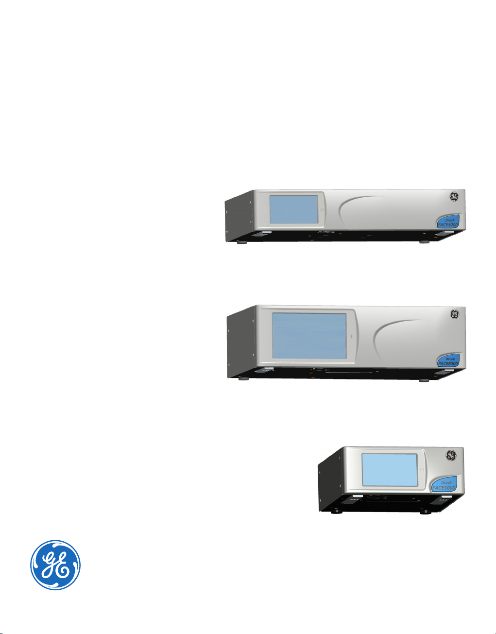
PACE5000
PACE6000
PACE1000
Page 2

© 2010 General Electric Company. All Rights Reserved. Specifications are subject to
change without notice. GE is a registered trademark of General Electric Company. Other
company or product names mentioned in this document may be trademarks or registered
trademarks of their respective companies, which are not affiliated with GE.
Page 3

PACE Series Calibration Manual
Introduction
This technical manual provides calibration instructions for the PACE Pressure Controllers and
Indicators.
The features shown and described in this manual may not be available on some models.
Safety
The manufacturer has designed this equipment to be safe when operated using the
procedures detailed in this manual. Do not use this equipment for any other purpose than
that stated.
This publication contains operating and safety instructions that must be followed to ensure
safe operation and to maintain the equipment in a safe condition. The safety instructions are
either warnings or cautions issued to protect the user and the equipment from injury or
damage.
Use suitably qualified* calibration technicians and good engineering practice for all
procedures in this publication.
Pressure
Do not apply pressures greater than the maximum working pressure to the equipment. It is
the responsibility of the calibration technician to apply pressures within the published
pressure range and to only use external pressure equipment with correctly rated fittings and
components.
Toxic Materials
There are no known toxic materials used in construction of this equipment.
Maintenance
The equipment must be correctly maintained, the manufacturer’s procedures should be
carried out by authorized service agents or the manufacturer’s service departments.
Technical Advice
For technical advice contact the manufacturer.
* A qualified calibration technician must have the necessary technical knowledge,
documentation, special calibration/test equipment and tools to carry out the required work
on this equipment.
[EN] English i K0450 Revision B
Page 4

Abbreviations
The following abbreviations are used in this manual; the abbreviations are the same in the
singular and plural.
abs Absolute
a.c. Alternating current
ALT Altitude
BSP British pipe thread
CAS Calculated airspeed
CSK Countersunk
d.c. Direct current
DPI Digital Pressure Instrument
e.g. For example
etc. And so on
Fig. Figure
ft Foot
g Gauge
Hg Mercury
HTS High tensile steel
Hz Hertz
IAS Indicated airspeed
i.e. That is
IEC International Electrotechnical Commission
IEEE 488 Institute of Electrical and Electronic Engineers standard 488 data
in Inch
kg Kilogram
kts/kn knot
LCD Liquid crystal display
m Metre
mA Milliampere
max Maximum
mbar Millibar
min Minute or minimum
mm Millimetre
mV Millivolts
MWP Maximum working pressure
No. Number
NPT National Pipe Thread
PACE Pressure Automated Calibration Equipment
Para. Paragraph
PDCR Pressure transducer
PED Pressure Equipment Directive
psi Pounds per square inch
PTX Pressure transmitter
ROC Rate of Climb
RS232 Serial communications data standard
RtCAS Rate of calculated airspeed
K0450 Revision B ii [EN] English
Page 5
RtMach Rate of Mach
SCPI Standard Commands for Programmable Instruments
UUT Unit under test
V Volts
VFC Volts-free contact
+ve Positive
-ve Negative
°C Degrees Celsius
Associated Publications
K0447 PACE5000/6000 User Guide and Safety Instructions
K0467 PACE1000 Indicator User Guide and Safety Instructions
K0443 PACE5000/6000 Controller User Manual
K0470 PACE1000 Indicator User Manual
K0476 Pressure Control Module User Guide and Safety Instructions
K0472 SCPI Communications Manual
K0469 Heritage Communications Manual - Instrument Emulation
Symbols
PACE Series Calibration Manual
This equipment meets the requirements of all relevant European safety directives.
The equipment carries the CE mark.
This symbol, on the equipment, indicates that the user should read the user
manual.
This symbol, on the equipment, indicates a warning and that the user should refer
to the user manual.
Ce symbole, sur l’instrument, indique que l’utilisateur doit consulter le manuel
d’utilisation. Ce symbole, dans le manuel, indique une situation dangereuse.
This symbol warns the user of the danger of electric shock.
Ce symbole alerte l’utilisateur sur le danger de choc électrique.
Do not dispose of this product as household waste. Use an approved organisation
that collects and/or recycles waste electrical and electronic equipment. For more
information, contact one of these:
- Our customer service department: www.gemeasurement.com
- Your local government office.
[EN] English iii K0450 Revision B
Page 6
WARNINGS
TURN OFF THE SOURCE PRESSURE(S) AND CAREFULLY VENT THE PRESSURE LINES BEFORE
DISCONNECTING OR CONNECTING THE PRESSURE LINES. PROCEED WITH CARE.
ONLY USE EQUIPMENT WITH THE CORRECT PRESSURE RATING.
BEFORE APPLYING PRESSURE, EXAMINE ALL FITTINGS AND EQUIPMENT FOR DAMAGE.
REPLACE ALL DAMAGED FITTINGS AND EQUIPMENT. DO NOT USE ANY DAMAGED
FITTINGS AND EQUIPMENT.
DO NOT EXCEED THE MAXIMUM WORKING PRESSURE OF THE INSTRUMENT.
THIS EQUIPMENT IS NOT RATED FOR OXYGEN USE.
THE GROUND LEAD OF THE INSTRUMENT MUST BE CONNECTED TO THE AC SUPPLY
PROTECTIVE SAFETY GROUND.
ISOLATE THE POWER SUPPLY BEFORE MAKING ANY ELECTRICAL CONNECTIONS TO THE
REAR PANEL.
K0450 Revision B iv [EN] English
Page 7

Pressure Units and Conversion Factors
Pressure units Factor (hPa) Pressure units Factor (hPa)
mbar 1.0
bar 1000.0
cmH
mH
O @ 20°C
2
O @ 20°C
2
PACE Series Calibration Manual
0.978903642
97.8903642
Pa (N/m
2
)
0.01
hPa 1.0
kg/m
kg/cm
2
2
0.0980665
980.665
kPa 10.0 torr 1.333223684
MPa 10000.0 atm 1013.25
mmHg @ 0°C 1.333223874 psi 68.94757293
cmHg @ 0°C 13.33223874
mHg @ 0°C 1333.223874
inHg @ 0°C 33.86388640341
mmH
cmH
mH
mmH
O @ 4°C
2
O @ 4°C
2
O @ 4°C
2
O @ 20°C
2
0.0980665
0.980665
98.0665
0.097890364
2
lb/ft
O @ 4°C
inH
2
inH
O @ 20°C
2
inH20 @ 60°F
ftH2O @ 4°C
ftH2O @ 20°C
ftH20 @ 60°F
0.4788025898
2.4908891
2.486413
2.487641558
29.8906692
29.836983
29.8516987
Unit Conversion
To convert FROM pressure VALUE 1 in pressure UNITS 1 TO pressure VALUE 2 in pressure
UNITS 2, calculate as follows:
VALUE 2 VALUE 1
FACTOR 1
=
---------------------FACTOR 2
Note: The PACE instrument contains selectable pressure units and user defined units. Use the
conversion factors to calculate a user defined unit from the table above. Refer to the
data sheets for the list of selectable pressure units.
[EN] English v K0450 Revision B
Page 8

Table of Contents
1 Introduction......................................................................................................................................................1
2 Calibration Status..........................................................................................................................................1
3 Calibration Equipment ................................................................................................................................1
4 Preliminary Operations...............................................................................................................................1
5 Notes on Calibration ....................................................................................................................................1
5.1 PACE Controller Connection .........................................................................................................2
Gauge Reference...............................................................................................................................2
5.2 PACE Indicator Connection...........................................................................................................3
Gauge Reference...............................................................................................................................3
6 Calibration Check (All Ranges).................................................................................................................4
6.1 Procedure..............................................................................................................................................4
7 Calibration Adjustment...............................................................................................................................5
Appendix A PACE Menus and Screens..................................................................................................6
A.1 PACE Controller Menus ...................................................................................................................6
A.2 PACE Controller Screens.................................................................................................................7
A.3 PACE Indicator Menus.....................................................................................................................8
A.4 PACE Indicator Screens ..................................................................................................................9
K0450 Revision B vi [EN] English
Page 9

PACE Series Calibration Manual
1 Introduction
The PACE controller incorporates a calibration facility; for the PACE to stay accurate, a
calibration check should be carried out at chosen intervals. If the accuracy of the PACE is not
within the permissible deviation, carry out a calibration adjustment.
2 Calibration Status
Using the Measured Pressure/Instrument Status menu, the calibration status of the
calibrator can be displayed on the front panel screen. The status menu includes Calibration
History which gives a list of dates of the stored calibration corrections.
Note: The Date and Time must be set correctly using the Measured Pressure/Global Set-up/
Calibration menu.
3 Calibration Equipment
The original GE Calibration Certificate shows the measurement uncertainty of the original
calibration standard. To preserve uncertainty of the PACE calibration, checks and
adjustments must be performed using a calibrator uncertainty of less than or equal to the
original calibration standard.
4 Preliminary Operations
Review and become familiar with the whole procedure before beginning a calibration
process. Allow at least one hour for the PACE to thermally stabilize in a thermally stable
environment after switching on and before calibration.
Before starting a calibration procedure:
Carry out a leak test as detailed in PACE user manual K0443.
5 Notes on Calibration
The pressure standard output port and the reference
level must be at the correct level or use heightcorrected applied pressure.
To prevent applied calibration pressure “back feed” in
PACE controllers, fit blanking plugs to both positive and
negative supply ports on the manifold.
Set the PACE units of pressure to one of the required units for calibration.
Reference
Level
[EN] English 1 K0450 Revision B
Page 10

5.1 PACE Controller Connection
WARNING
ON COMPLETION OF CALIBRATION, OPEN THE ON/OFF VALVE TO VENT TRAPPED
PRESSURE FROM THE SUPPLY + PORT TO ATMOSPHERE.
Connect the calibrator for each pressure range as follows:
Connect the output of the pressure standard to the PACE module output port.
Fit an on/off valve to the supply + input of the PACE controller. Leave the other side of the
valve open to atmosphere. Turn the valve to the closed position.
Gauge Reference
If the pressure standard has a reference connection, then connect this to the PACE reference
port on the module manifold. Otherwise the calibrator reference port should be open to
atmosphere.
PACE Controller
Module 2
SUPPLY
+-
OUTLET VENT REF
On/off valve fitted to supply +
SUPPLY
+-
Rear view of
instrument
Module 1
OUTLET VENT REF
Pressure Standard
Note: Module 2 reference port open to atmosphere or to reference port of the pressure
standard.
Note: Optimum performance is achieved by connecting the PACE reference port to the
pressure standard.
K0450 Revision B 2 [EN] English
Page 11

PACE Series Calibration Manual
5.2 PACE Indicator Connection
Connect the indicator for each pressure range as follows:
Connect the output of the pressure standard to the indicator port.
Gauge Reference
If the pressure standard has a reference connection, then connect this to the indicator
reference port. Otherwise the indicator reference port should be open to atmosphere.
PACE Indicator
SENSOR
PORT
REFERENCE
PORT
Pressure Standard
Rear view of
instrument
Note: Indicator reference port open to atmosphere or to reference port of the pressure
standard.
Note: Optimum performance is achieved by connecting the PACE reference port to the
pressure standard.
[EN] English 3 K0450 Revision B
Page 12

6 Calibration Check (All Ranges)
Note: The PACE adds the barometric reading to a gauge range to produce an absolute range.
6.1 Procedure
Set the calibrator to measure mode:
1 Connect calibration standard for the pressure range to be checked.
2 Press Task and select Basic.
3 With the pressure standard connected to the correct pressure port, select Measured
Pressure and press Range to select the gauge pressure range to be checked.
4 Barometric pressure can be displayed in the status area.
5 Set maximum displayed resolution.
Gauge ranges should be zeroed immediately prior to a calibration check, as follows:
1 Press Measured Pressure/Zero to zero the selected range.
2 On completion of the zero operation, the display shows Zero completed successfully.
3 Adjust calibration pressure to the first pressure value and wait until this pressure, as
displayed on PACE, is stable to less than 10ppm (0.001%). Display filtering may be
required.
4 Compare the pressure value on the calibration standard to the value displayed and
record the difference.
5 Repeat (3) and (5) for each pressure, as prompted by the PACE.
6 If the recorded difference exceeds the permissible deviation for the selected range, the
calibrator requires a calibration adjustment for that range. Refer to PACE sales data
sheets for permissible precision deviation. Precision specification is used if less than 24
hours since adjustment using the same calibration equipment. If greater than 24
hours, then the PACE specification is the sum of precision and long term stability.
7 Select the next pressure range for a calibration check.
8 After completing all calibration checks, adjust calibration standard to atmospheric
pressure.
9 Disconnect calibration standard from the output.
If no further calibration is required, switch off the PACE.
K0450 Revision B 4 [EN] English
Page 13

PACE Series Calibration Manual
7 Calibration Adjustment
To adjust a calibration range of the calibrator, proceed as follows:
1 Connect the calibrator for the range to be adjusted, as detailed in Calibration Check.
Note: The calibration adjustments may be carried out in any order.
2 Select Measured Pressure/Global Set-up/Calibration, enter the Calibration PIN
(4321).
3 Select Sensor Correction.
4 Select the pressure range to be corrected.
5 Select New Calibration.
6 The display shows the first value to be set on the pressure standard and to press OK
when the applied pressure is stable. Use the numeric keys to enter the precise applied
pressure.
Note: The display also shows throughout this procedure the message Calibrating and the
selected pressure range.
7 Select Accept to store the first value and the display goes to the next pressure value to
be set.
8 Select Repeat to re-apply the same pressure and Quit Calibration to exit the
calibration of this pressure range.
9 Repeat steps (5) to (7) for the next value.
10 Carry out a calibration check to verify this procedure.
11 After completing the calibration procedures, adjust the calibration standard to
atmospheric pressure. Disconnect calibration standard from the PACE.
[EN] English 5 K0450 Revision B
Page 14

Appendix A PACE Menus and Screens
A.1 PACE Controller Menus
Calibration procedure next page
K0450 Revision B 6 [EN] English
Page 15

A.2 PACE Controller Screens
PACE Series Calibration Manual
[EN] English 7 K0450 Revision B
Page 16

A.3 PACE Indicator Menus
Calibration procedure next page
K0450 Revision B 8 [EN] English
Page 17

A.4 PACE Indicator Screens
PACE Series Calibration Manual
[EN] English 9 K0450 Revision B
Page 18

Page 19

Page 20

www.gemeasurement.com
 Loading...