

Page 1

GE
Intelligent Platforms
Programmable Control Products
PAC8000* IO
PROFINET Scanner
User’s Manual, GFK-2839B
September 2017
Page 2
2 PAC8000* IO PROFINET Scanner User’s Manual–September 2017 GFK-2839B
GFL-002
Warnings, Cautions and Notes
as Used in this Publication
Warning
Warning notices are used in this publication to emphasize that
hazardous voltages, currents, temperatures, or other conditions
that could cause personal injury exist in this equipment or may
be associated with its use.
In situations where inattention could cause either personal injury
or damage to equipment, a Warning notice is used.
Caution
Caution notices are used where equipment might be damaged if
care is not taken.
Note: Notes merely call attention to information that is especially significant to
understanding and operating the equipment.
This document is based on information available at the time of its publication. While efforts
have been made to be accurate, the information contained herein does not purport to cover
all details or variations in hardware or software, nor to provide for every possible contingency
in connection with installation, operation, or maintenance. Features may be described herein
which are not present in all hardware and software systems. GE Intelligent Platforms
assumes no obligation of notice to holders of this document with respect to changes
subsequently made.
GE Intelligent Platforms makes no representation or warranty, expressed, implied, or
statutory with respect to, and assumes no responsibility for the accuracy, completeness,
sufficiency, or usefulness of the information contained herein. No warranties of
merchantability or fitness for purpose shall apply.
* indicates a trademark of GE Intelligent Platforms, Inc. and/or its affiliates. All
other trademarks are the property of their respective owners.
©Copyright 2013 GE Intelligent Platforms, Inc.
All Rights Reserved
Page 3
Contact Information
GFK-2839B PAC8000* IO PROFINET Scanner User’s Manual –September 2017 3
If you purchased this product through an Authorized Channel Partner, please contact the
seller directly.
General Contact Information
Online technical support and GlobalCare
http://www.ge-ip.com/support
Additional information
http://www.ge-ip.com/
Solution Provider
solutionprovider.ip@ge.com
Technical Support
If you have technical problems that cannot be resolved with the information in this guide,
please contact us by telephone or email, or on the web at www.ge-ip.com/support
Americas
Online Technical Support
www.ge-ip.com/support
Phone
1-800-433-2682
International Americas Direct Dial
1-780-420-2010 (if toll free 800 option is unavailable)
Technical Support Email
support.ip@ge.com
Customer Care Email
customercare.ip@ge.com
Primary language of support
English
Europe, the Middle East, and Africa
Online Technical Support
www.ge-ip.com/support
Phone
+800-1-433-2682
EMEA Direct Dial
+420-23-901-5850 (if toll free 800 option is unavailable
or dialing from a mobile telephone)
Technical Support Email
support.emea.ip@ge.com
Customer Care Email
customercare.emea.ip@ge.com
Primary languages of support
English, French, German, Italian, Czech, Spanish
Asia Pacific
Online Technical Support
www.ge-ip.com/support
Phone
+86-400-820-8208
+86-21-3217-4826 (India, Indonesia, and Pakistan)
Technical Support Email
support.cn.ip@ge.com (China)
support.jp.ip@ge.com (Japan)
support.in.ip@ge.com (remaining Asia customers)
Customer Care Email
customercare.apo.ip@ge.com
customercare.cn.ip@ge.com (China)
Page 4

Page 5

Contents
GFK-2839B PAC8000* IO PROFINET Scanner User’s Manual–September 2017 5
Chapter 1. Introduction ...................................................................................... 7
1.1 PAC8000 PROFINET Scanner Overview ..................................................................7
1.2 PAC8000 PROFINET Scanner Versions ...................................................................8
1.3 PAC8000 PROFINET Scanner Specifications ...........................................................9
1.4 PAC8000 PROFINET Scanner Controls and Indicators ......................................... 10
1.4.1 PAC8000 PROFINET Scanner LEDs ............................................................ 10
1.4.2 Power Supplies .............................................................................................. 11
1.4.3 External BFP (Bussed Field Power Supply) Monitoring ................................ 12
1.4.4 12V DC HVCC/PNS Power supply monitoring .............................................. 12
1.4.5 Ethernet Network Ports .................................................................................. 13
1.4.6 USB Port ........................................................................................................ 16
1.5 Compatible PAC8000 IO Modules, Carriers, and Power Supplies ......................... 17
1.5.1 IO Modules ..................................................................................................... 17
1.5.2 IO Carrier ....................................................................................................... 17
1.5.3 PNS Carrier .................................................................................................... 17
1.5.4 Power Supply Requirements ......................................................................... 18
Chapter 2. Hardware Installation ..................................................................... 19
2.1 Module Installation .................................................................................................. 19
2.2 Cable and Connector Clearance Requirements ..................................................... 21
2.3 Installation in Hazardous Areas ............................................................................... 22
2.3.1 ATEX Marking ................................................................................................ 22
2.3.2 CE Marking .................................................................................................... 22
2.4 Installing the Module on a DIN Rail ......................................................................... 23
2.5 Removing the Module from the DIN Rail ................................................................. 24
2.6 Panel Mounting........................................................................................................ 24
2.7 Grounding ................................................................................................................ 25
2.8 Connecting Power Supplies to PAC8000 PROFINET Scanner .............................. 25
2.9 PAC8000 PROFINET Scanner Power-up and Restart ........................................... 26
2.10 LED Operation ......................................................................................................... 27
2.10.1 Special LED Blink Patterns ............................................................................ 28
2.11 Firmware Updates ................................................................................................... 29
2.11.1 Firmware Update for IO Modules in the PNS ................................................ 29
2.12 Installing the USB Port Driver .................................................................................. 30
Chapter 3. Configuration ................................................................................. 31
3.1 Configuration Overview ........................................................................................... 31
3.1.1 Basic Configuration Steps .............................................................................. 32
3.1.2 Configuration Tool .......................................................................................... 32
3.2 Adding a PAC8000 PROFINET Scanner to a LAN ................................................. 33
3.2.1 Configuring PAC8000 PROFINET Scanner Parameters ............................... 33
3.2.2 Configuring PAC8000 PROFINET Scanner Parameters ............................... 36
3.3 Assigning IO-Device Names ................................................................................... 37
Page 6

Contents
6 PAC8000* IO PROFINET Scanner User’s Manual–September 2017 GFK-2839B
3.4 Clearing the IO-Controller Configuration ................................................................. 37
3.5 Replacing PAC8000 PROFINET Scanner Hardware.............................................. 37
Chapter 4. Diagnostics .................................................................................... 38
4.1 PNS Status and Control Data .................................................................................. 38
4.1.1 Output Control Register ................................................................................. 38
4.1.2 Input Status Registers .................................................................................... 39
4.2 Error Handling ......................................................................................................... 41
4.2.1 Fatal Error Handling ....................................................................................... 41
4.2.2 PROFINET Diagnostics ................................................................................. 42
4.2.3 Clearing Faults on PAC8000 Modules ........................................................... 45
4.2.4 PROFINET Module Loss, Add and Mismatch Faults .................................... 46
Chapter 5. PROFINET Specifications .............................................................. 47
5.1 PROFINET Protocol Support .................................................................................. 47
5.2 Technical Data......................................................................................................... 47
5.3 Limitations ............................................................................................................... 48
Page 7
Index
GFK-2839B PAC8000* IO PROFINET Scanner User’s Manual–September 2017 7
Chapter 1. Introduction
This chapter provides an overview of the PAC8000 PROFINET Scanner (PNS) module and
its operation. This chapter also includes a list of the PAC8000 IO modules that can be
included in the PAC8000 PROFINET Scanner IO-Device.
Chapter 2, Installation, gives instructions for PNS installation, panel-mounting, grounding,
installing power supplies, and updating firmware. It also describes powerup and restart, and
LED operation.
Chapter 3, Configuration, describes how to configure the PNS and its IO modules.
Chapter 4, Diagnostics, describes the input and output data that can be used to monitor and
control the PNS. This chapter also explains how the PNS reports errors to the control system.
Chapter 5, PROFINET Specifications, summarizes the features specified for PROFINET
v2.3 Class A IO-Devices that are supported by the PAC8000 PROFINET Scanner module.
1.1 PAC8000 PROFINET Scanner Overview
The PAC8000 PROFINET Scanner (PNS) module interfaces PAC8000 IO modules to a
PROFINET IO network. The PNS scans the input modules in the node (retrieving input data
and providing output data), publishes input data on the PROFINET network at the configured
update rate, and receives data for output module outputs.
The PNS manages PROFINET communication and IO module configuration between an IOController and IO modules of PNS. If network communications are lost, the PNS manages I/O
states according to the individual module configurations.
Input and Output data are coherent over a full scan of the IO modules. All input data read
from one scan of the IO modules is kept together and then sent over the PROFINET network.
Similarly, outputs delivered on the network are sent to the IO modules as a unit. If new
outputs arrive during the writing of data to the output modules, the PNS continues to write to
the outputs using the previous data until all IO modules have been updated before switching
to the newly delivered data.
Page 8
Contents
8 PAC8000* IO PROFINET Scanner User’s Manual–September 2017 GFK-2839B
1.2 PAC8000 PROFINET Scanner Versions
The PNS network interface module is available in two versions to allow you to use the
network media that meet the requirements of your application.
8515-BI-PN: Two 10/100 Mbps copper RJ-45 media connectors supporting shielded
(refer Note below) and unshielded cables (CAT 5 and above)
8516-BI-PN: Two 100Mbps Multimode SC–Duplex fiber optic media connectors
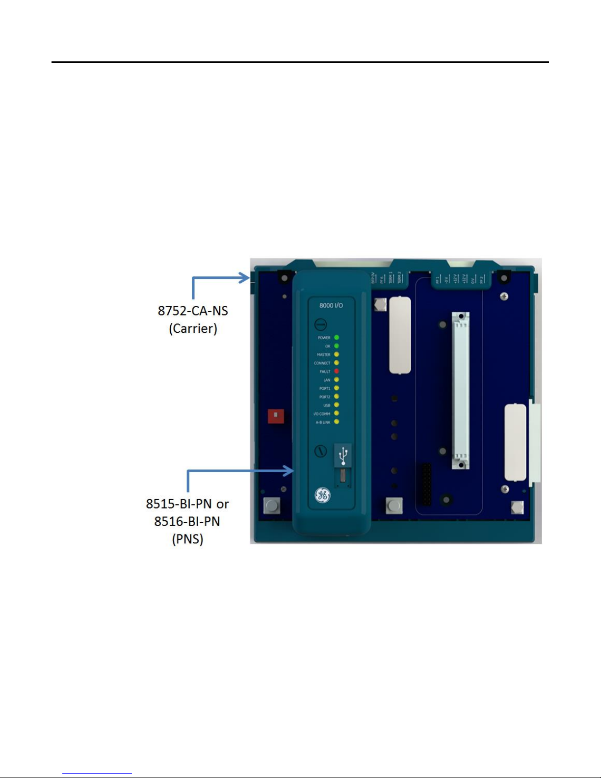
The above PNS modules require the following carrier.
8752-CA-NS: PAC8000 Node Service Carrier
The PNS uses external 12V DC power supply. Optionally user can use two power supplies
having redundancy feature.
Note: The shield connections of RJ45 connectors on 8515-BI-PN module get connected to
the system ground through a capacitor internally, when the module is installed on the carrier.
Page 9

Index
GFK-2839B PAC8000* IO PROFINET Scanner User’s Manual–September 2017 9
1.3 PAC8000 PROFINET Scanner Specifications
PROFINET Support
PROFINET Version 2.3 Class A IO-Device
Redundantly controlled operation conforms to PROFINET V2.3 Type
S2 System Redundancy.
RX3i PLC CPU Version
Required
Firmware version 7.0 or later
Proficy Machine Edition
Version Required
Version 7.5 SIM 3 or later
V2.3 GSDML and Proficy Machine Edition/3rd-Party tools.
Power Requirements
8515-BI-PN 4.5 Watts (5.5 Watts Max)
8516-BI-PN 6.0 Watts (7.2 Watts Max)
Module Dimensions
Length: 160.3mm (6.31”), Width: 128.3mm (5.05")
Thickness 47.78mm (1.88”)
Carrier Required
8752-CA-NS : PAC8000 Node Service Carrier
Operating Temperature
Range
8515-BI-PN -40˚C to +70˚C
8516-BI-PN -40˚C to +70˚C
Horizontal DIN rail mounting.
Optimum orientation is when the carrier is mounted in a vertical plane
with field terminals for communication cables located below the
modules.
Number of Port
Connectors
8515-BI-PN : Two RJ-45
8516-BI-PN : Two SC-Duplex
USB Connector (for
firmware upgrades)
One Micro-B connector. USB 2.0 compliant running at full speed
(12 MHz)
PNS Status and Control
Bits
64 input status bits and 48 output control bits
I/O Data Update on the
PROFINET LAN
Configurable: 1ms, 2ms, 4ms, 8ms, 16ms, 32ms, 64ms, 128ms, 256ms
and 512ms (Recommended is 4 ms and above)
Number of IP addresses
One. Supports Classless Inter-Domain Routing (CIDR)
Number of MAC
Addresses
Three. One per external port and one internal. External MAC addresses
are only used for specialized Ethernet protocols such as MRP or LLDP
I/O Station Maximum
Limits
Number of IO Modules per
Node
32
IO data per station
2880 bytes total
1440 bytes of input data
1440 bytes of output data
RoHS Compliance
Yes
Configuration
Configured using Proficy Machine Edition when used with a
PACSystems RX3i PROFINET Controller (PNC) module, as part of an
RX3i PROFINET network.
V2.3 GSDML file is available for import into 3rd-Party tools.
For product standards, general operating specifications, and installation requirements, refer
to the PAC8000 IO modules Manual, INM8200.pdf.
Page 10

Contents
10 PAC8000* IO PROFINET Scanner User’s Manual–September 2017 GFK-2839B
1.4 PAC8000 PROFINET Scanner Controls and Indicators
The illustration below shows a PAC8000 PROFINET Scanner.
1.4.1 PAC8000 PROFINET Scanner LEDs
POWER LED
Power Supply LED is ON solid green when power is being supplied on the power supply
connector.
OK LED
The OK LED is solid green ON for normal operation.
MASTER LED
This LED is reserved.
CONNECT LED
When a new PNS module powers up for the first time, it has no network name. The
CONNECT LED slowly blinks to indicate that the module is not ready to use. After a name is
assigned, the CONNECT LED goes OFF.
If the PNS has an assigned network name, the CONNECT LED is OFF after a successful
power up. It turns ON solid when the IO-Controller has established communications with the
PNS module. It turns OFF when communications are terminated.
Page 11

Index
GFK-2839B PAC8000* IO PROFINET Scanner User’s Manual–September 2017 11
FAULT LED
The FAULT LED remains OFF during normal operation when no PROFINET Diagnosis
conditions are present on the PNS itself or any IO module in the node. When a PROFINET
Diagnosis condition exists, the FAULT LED turns solid red. When all diagnosis conditions
have disappeared, the FAULT LED is OFF.
The FAULT LED blinks red (0.5 seconds ON/0.5 seconds OFF) if any of the MAC addresses
read from non-volatile memory on power-up are invalid. The PNS remains disconnected from
the Ethernet network if any of its MAC addresses are invalid.
Missing or mismatched IO modules in the PNS node do not affect the PNS FAULT LED.
LAN LED
The LAN LED blinks ON when the PNS module is actively processing Ethernet packets
(Tx/Rx). The LAN LED is OFF if there is no activity.
Port LEDs (10/100 Mbps and Link/Activity)
The two Port LEDs indicate link connection and link activity on the Ethernet ports. If a PORT
LED is solid ON, the port is connected but is not currently receiving or transmitting Ethernet
frames. A Port LED blinks when Ethernet frames are actively being transmitted or received.
USB LED
The USB LED is OFF when a USB connection is not established and ON when the link with a
computer is ready. The USB LED flashes when there is traffic such as Winloader activity on
the port.
I/O COMM
This LED turns ON when all IO module commands were successful in the last two seconds. It
blinks when at least one IO module command failed in the last two seconds. It remains OFF
when no IO module command was sent in the last two seconds.
A-B LINK
This LED is reserved.
1.4.2 Power Supplies
The PAC8000 PROFINET Scanner can be connected with either one power supply or dual
redundant power supplies. If two power supplies are installed, they serve as redundant
backups for each other.
Page 12
Contents
12 PAC8000* IO PROFINET Scanner User’s Manual–September 2017 GFK-2839B
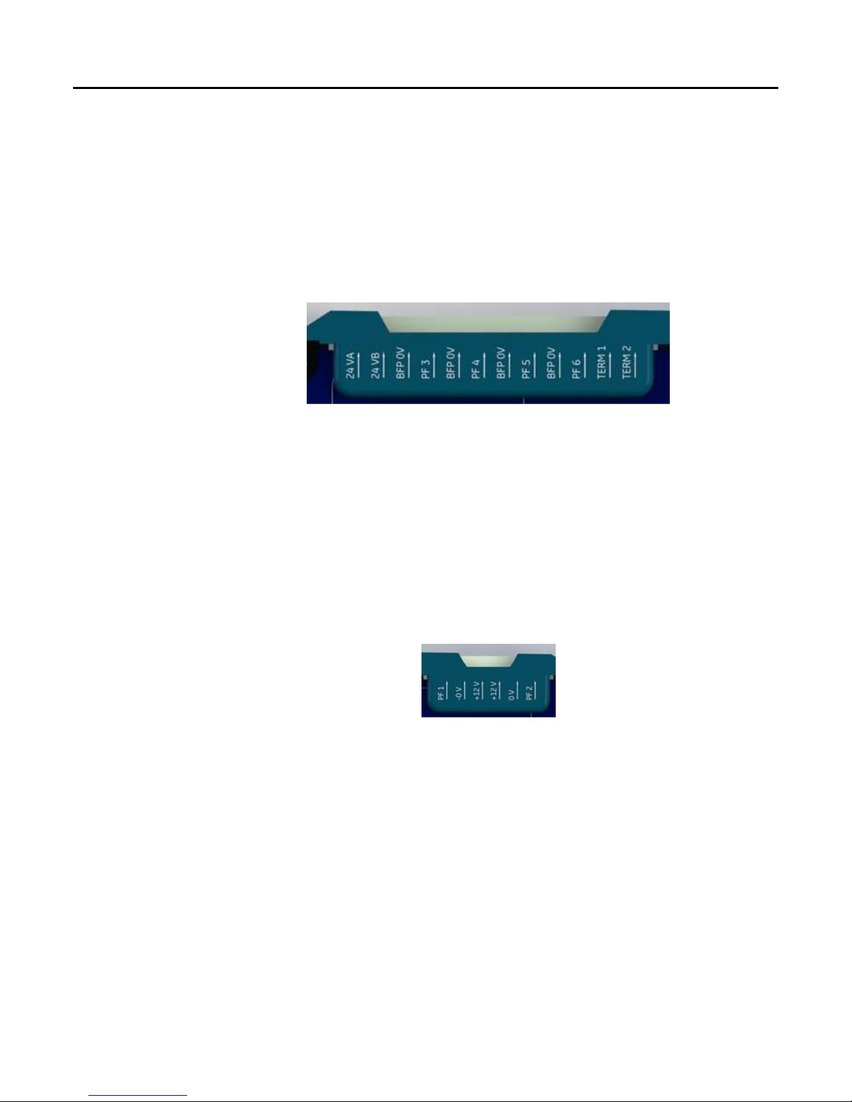
1.4.3 External BFP (Bussed Field Power Supply) Monitoring
The status of up to four Bussed Field Power supplies can be monitored through the status
bits of the PNS. For details, see 4.1.2.3, “PNS Power Status Register (PPSR).” The Bussed
Field Power monitoring connector is shown in the picture below. There are two terminal
marked as 24VA and 24VB provided for connecting the 24V terminal (+) of the power supply.
There are four terminals marked as BFP0V are provided to connect the 0V terminal (-). The
power status signals from the power supplies are required to be connected to terminals
marked as PF3, PF4, PF5 and PF6. Please note that this functionality shall only work if the
power status signal is “open-collector” type: low impedance to BFP0V when power is OK and
high impedance if power fails.
The terminal marked as “TERM1” & “TERM2” are reserved for future use.
1.4.4 12V DC HVCC/PNS Power supply monitoring
The status of up to two redundant 12V Power supplies (HVCC and/or PNS power) can be
monitored through the status bits of the PNS. For details, see 4.1.2.3, “PNS Power Status
Register (PPSR).” The HVCC connector is shown in the picture below. The power status
signals from the power supplies are required to be connected to terminals marked as PF1
and PF2. Please note that this functionality shall only work if the power status signal is “opencollector” type: low impedance to GND when power is OK and high impedance if power fails
Page 13
Index
GFK-2839B PAC8000* IO PROFINET Scanner User’s Manual–September 2017 13
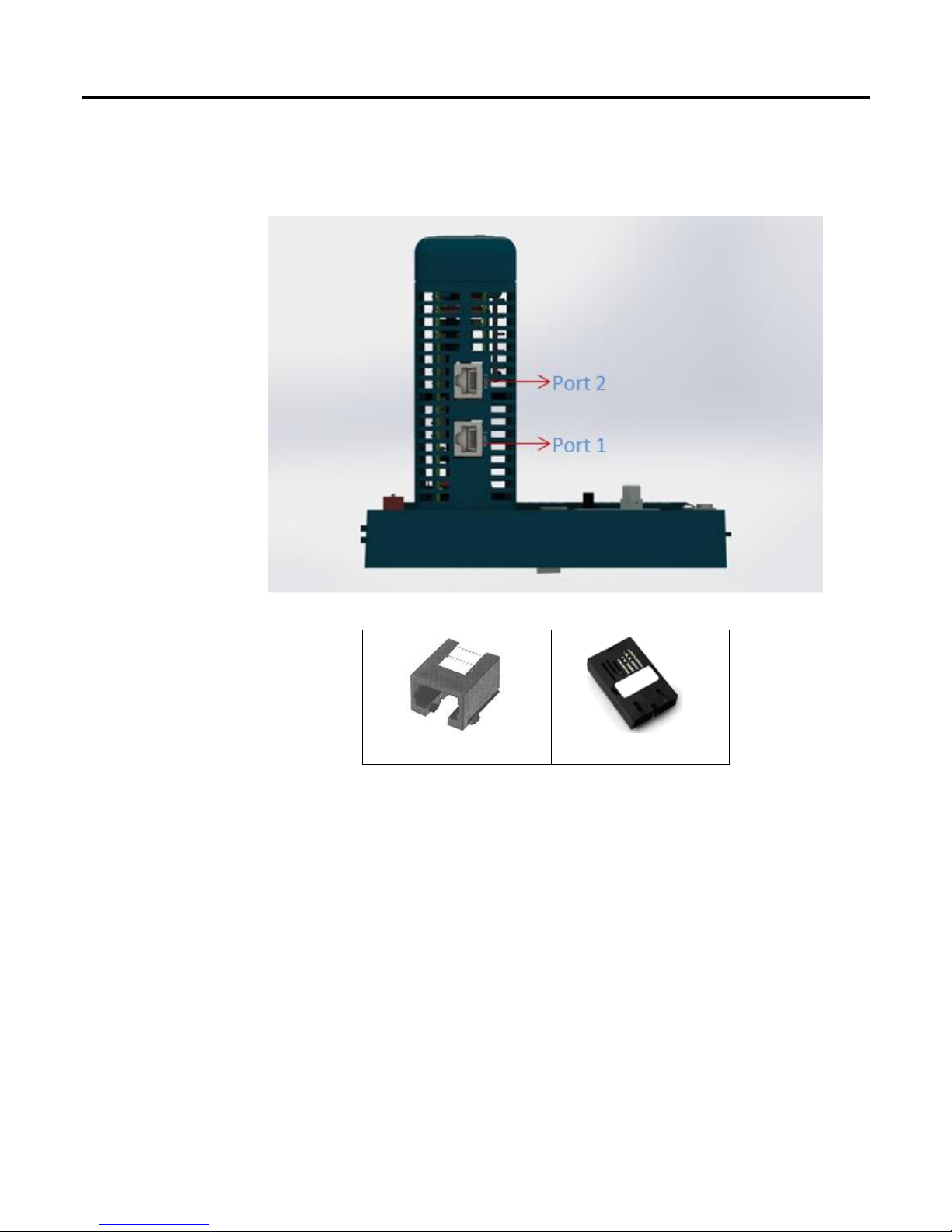
1.4.5 Ethernet Network Ports
The two external Ethernet ports are on the bottom of the module. The illustration below is a
side view of 8515-BI-PN with its two RJ-45 ports.
8515-BI-PN (Copper)
RJ-45 Port
SC-Duplex Port
Page 14
Contents
14 PAC8000* IO PROFINET Scanner User’s Manual–September 2017 GFK-2839B
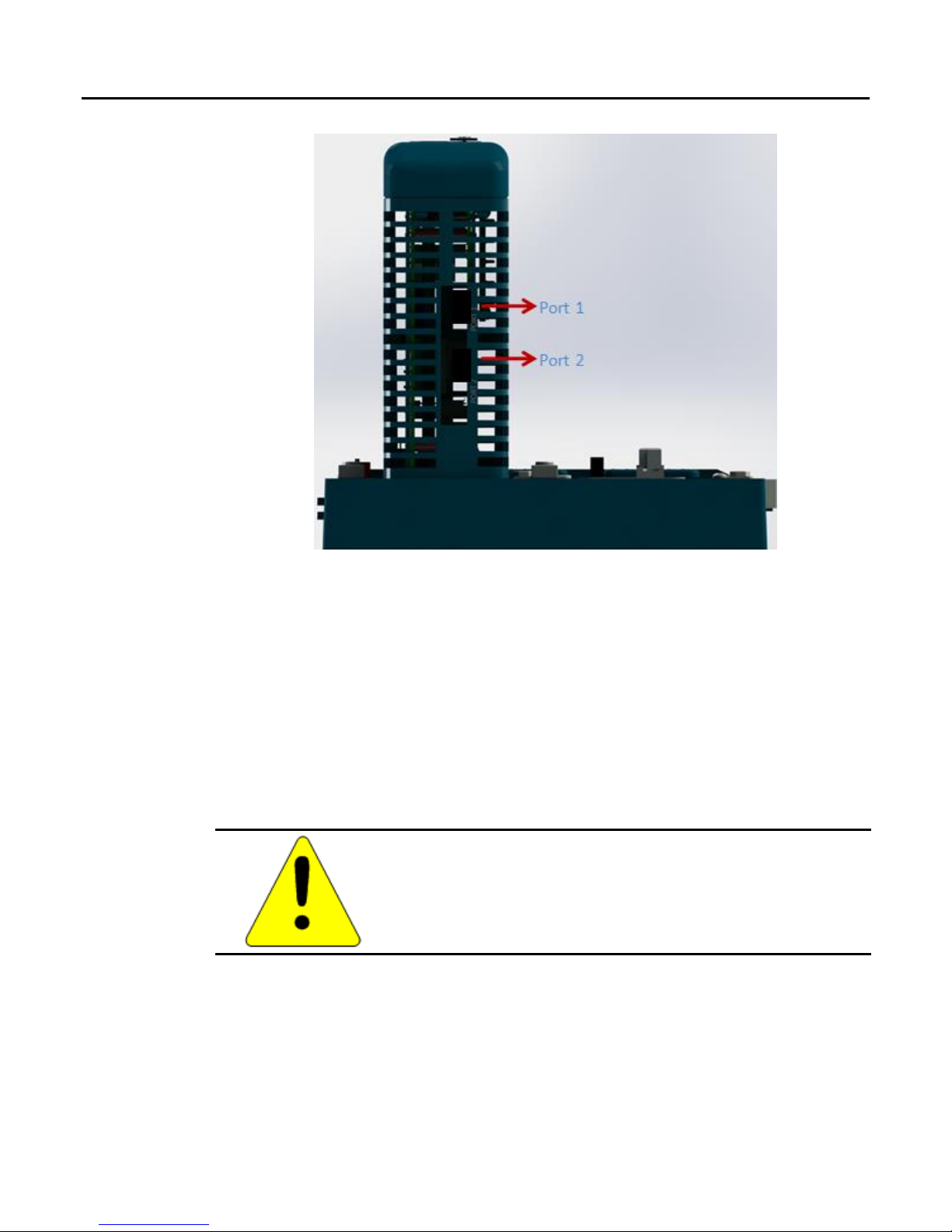
8516-BI-PN (Fiber)
Model 8515-BI-PN has two RJ-45 ports, providing 10/100 Mbps copper interfaces. Model
8516-BI-PN has two SC-Duplex ports, providing 100Mbps Multimode fiber interfaces. Each
Ethernet port automatically senses the type of network and adjusts speed and connection
parameters. The PNS requires at least one port be operating at full duplex for a connection to
remain established. The PROFINET protocol may be sent and received over either or both of
the two external ports.
Devices connected to the PNS ports should have Ethernet Autonegotiation enabled unless
the IO-Controller supports configuring the port operation mode. If the IO-Controller configures
the PNS port to a specific setting with autonegotiation disabled, the device connected to the
PNS must be configured for the exact same setting.
Caution
Both ports on the Ethernet Interface must not be connected,
directly or indirectly, to the same device so as to form a circular
network unless Media Redundancy is enabled with one node
actively set up as the Media Redundancy Manager.
Page 15

Index
GFK-2839B PAC8000* IO PROFINET Scanner User’s Manual–September 2017 15
The PNS supports the following network media type and distances.
Media Type
Connector
Type
Wavelength
(nm)
Media
Type
Core
Size(μm)
Modal Bandwidth
(MHz – Km)
Distance (m)
100BASE-FX
SC or
SC-Duplex
1300
MMF
62.5
500
2 – 2,000
(Full Duplex)
2 – 400
(Half Duplex)
50
400
50
500
10/100BASE-T
RJ45
-
CAT5/
CAT5e/
CAT6
- - 100
(maximum)
PAC8000 PNS modules and other participating modules can be connected in a
daisy-chain/line, star, or ring (redundant media) topology.
Page 16

Contents
16 PAC8000* IO PROFINET Scanner User’s Manual–September 2017 GFK-2839B
1.4.5.1 Media Redundancy Protocol Support
PROFINET Media Redundancy Protocol (MRP) supports devices configured in a ring
topology. It is based on the functions of IEC62439. Media Redundancy Protocol is not
routable between different IP subnets.
Each device within a Redundant Media network has at least two physical pathways to two
other devices on the network. To connect to the ring, each device requires an integrated
switch with at least two external ports (ring ports) that support Media Redundancy Protocol.
Devices that are not MRP-capable can be connected to a device like an MRP-capable switch
in the ring, but they cannot be in the ring themselves. The redundant paths only extend to the
devices on the ring that are MRP-capable and enabled.
One of the devices on the ring must be configured as the Media Redundancy Manager
(MRM), and all the other devices must be configured as Media Redundancy Clients (MRCs).
The PNS can be configured to be an MRC. Configuring the PNS as an MRC alters how the
Ethernet ports connect to the network. They attempt to indicate their state to the MRM before
allowing traffic to flow between the ports and close the ring topology through the internal
switch. They also send out notifications to the MRM when a port is lost. Operation of the PNS
is otherwise unchanged.
1.4.6 USB Port
The USB port, below LEDs, on the faceplate behind the cover on PNS, can be used to
connect a computer for firmware updates of the PAC8000 PNS. The USB port accepts a
standard USB cable (USB Micro B Male to USB Type A Male, not included). The port must
be set up before using it, as described in chapter 2.
Note: The USB port is for firmware upgrades only. It is not intended for permanent
connection.
Page 17

Index
GFK-2839B PAC8000* IO PROFINET Scanner User’s Manual–September 2017 17
1.5 Compatible PAC8000 IO Modules, Carriers, and Power Supplies
1.5.1 IO Modules
The following modules can be used in a PAC8000 PROFINET Scanner IO-Device:
Module
Type
Catalog No.
Description
Standard Modules
8101-HI-TX
8-channel Analog Input Module, 4–20 mA
8102-HO-IP
8-channel Analog Output Module, 4–20 mA
8103-AI-TX
8-channel Analog Input Module, 4–20 mA
8104-AO-IP
8-channel Analog Output Module, 4–20 mA
8109-DI-DC
8-channel Discrete Input Module, 24 V dc, isolated, sinking
8110-DI-DC
8-channel Discrete Input Module, 24 V dc, non-isolated, module powered
8111-DI-AC
8-channel Discrete Input Module, 115 V ac, isolated, sinking
8112-DI-AC
8-channel Discrete Input Module, 115 V ac, non-isolated, module powered
8113-DI-AC
8-channel Discrete Input Module, 230 V ac, isolated, sinking
8114-DI-AC
8-channel Discrete Input Module, 230 V ac, non-isolated, module powered
8115-DO-DC
8-channel Discrete Output Module, 2–60 V dc, non-isolated, module powered
8116-DO-AC
8-channel Discrete Output Module, 20–265 V ac, non-isolated, module powered
8117-DO-DC
8-channel Discrete Output Module, 2–60 V dc, isolated, unpowered
8118-DO-AC
8-channel Discrete Output Module, 20–265 V ac, isolated, unpowered
8119-VI-05
8-channel Analog Input Module, 1–5 V
8121-DI-DC
16-channel Discrete Input Module, 24 V dc, non-isolated, module powered
8122-DI-DC
16-channel Discrete Input Module, 24 V dc, isolated, sinking
8125-DI-DC
32-channel Discrete Input Module, Switch/Proximity Detector Inputs, Module
Powered
8132-AI-UN
8-channel, 4-20mA, Thermocouple, RTD and Voltage isolated, universal input
8140-DI-AC
16-channel Discrete Input Module, 115 V ac, block-isolated, sinking
8142-DO-DC
16-channel Discrete Output Module, 12-42 V dc, non-isolated, module powered
Intrinsic Safe Modules
8201-HI-IS
8-channel Analog Input Module, 4–20 mA
8202-HO-IS
8-channel Analog Output Module, 4–20 mA
8204-AO-IS
8-channel Analog Output Module, 4–20 mA
8215-DO-IS
4-channel Discrete Output Module, solenoid driver, IIC gas groups
8230-AI-IS
8-channel, intrinsic Analog input module (Voltage/Potentiometer)
8206-TI-IS
8-channel, intrinsic Temperature input module (RTD/Ohms)
8220-16-DI-IS
16-channel, intrinsic Digital input module, Proximity Detector
1.5.2 IO Carrier
8709-CA-08, 8729-CA-08
1.5.3 PNS Carrier
8752-CA-NS: Node Service Carrier
Page 18

Contents
18 PAC8000* IO PROFINET Scanner User’s Manual–September 2017 GFK-2839B
1.5.4 Power Supply Requirements
1. The power supply shall have output ratings of 12V DC, 5 A with power fail signal.
2. The power supply shall be current limited and shall meet the output entity parameter
requirements as per our drawing no. SCI-1520 / SCI-1526.
3. It shall comply to class A emission requirements as per CISPR-11.
4. It shall comply to EMC immunity requirements such as surge (2kV) and EFT (2kV).
5. It shall be ATEX marked, CE marked and UL or CSA listed to Class 1 Division 2, Group
A, B, C, D.
6. The power-fail output of the power supply shall be an open-collector output only, capable
of working with maximum 15V pull-up externally connected
For power supply cable and connector for the PAC8000 PNS, refer to part number
8421-CC-PS.
Page 19

Index
GFK-2839B PAC8000* IO PROFINET Scanner User’s Manual–September 2017 19
Chapter 2. Hardware Installation
This chapter describes:
■ Module Installation
o Installing the Module on a DIN Rail
o Removing the Module from the DIN Rail
o Panel-Mounting
o Grounding
o Installing Power Supplies
■ PNS Powerup and Restart
■ LED Operation
o Special LED Blink Patterns
■ Firmware Updates
o Installing the USB Port Driver
2.1 Module Installation
PNS module must be mounted on a horizontal DIN rail. The PNS module fits into a 156mm
deep enclosure.
Rated thermal specifications are based on a minimum clearance of 5.1cm (2 inch) above and
below the module.
In addition to clearances required for cooling, space must be allowed for the following
requirements:
Allow adequate clearance for communications port cables. For an example, see
below sections.
Allow adequate clearance for power wiring.
1
2
Page 20

Contents
20 PAC8000* IO PROFINET Scanner User’s Manual–September 2017 GFK-2839B
Page 21

Index
GFK-2839B PAC8000* IO PROFINET Scanner User’s Manual–September 2017 21
2.2 Cable and Connector Clearance Requirements
You may need to allow more space for installation of cables and connectors than what is
required for heat dissipation. To avoid impacting mechanical reliability and signal quality,
cable installation must comply with the minimum bend radius specified by the cable
manufacturer.
Cable Clearance Example
In this example, an 8516-BI-PN module is installed with a fiber optic cable that has the
following characteristics:
SC-Duplex connector length: 27mm (1.07 inches)
Manufacturer-recommended long-term minimum bend radius: 30mm (1.2 inches)
The minimum clearance required to insert the connector into a port is 57mm (2.27 inches).
Additional clearance is recommended to provide physical access. In the case of the
8516-BI-PN, the space required for cabling will be greater than the space required to meet
thermal ratings.
1
2
Page 22

Contents
22 PAC8000* IO PROFINET Scanner User’s Manual–September 2017 GFK-2839B
2.3 Installation in Hazardous Areas
The following information is for products bearing the UL marking for Hazardous
Locations or ATEX marking for explosive atmospheres:
• EQUIPMENT LABELED WITH REFERENCE TO CLASS I, DIVISION 2, GROUPS A,
B, C & D, HAZARDOUS LOCATIONS (ALTERNATIVELY MARKED AS CLASS I
ZONE 2, GROUP IIC) IS SUITABLE FOR USE IN CLASS I, DIVISION 2, GROUPS
A, B, C, D OR NON-HAZARDOUS LOCATIONS ONLY
▪ Equipment labeled with II 3 G is suitable for use in Group 2 Category 3
environments.
▪ Connectors P1, J101 & HVCC shall be secured properly with the mechanical latch
provided for the purpose.
• WARNING - EXPLOSION HAZARD - SUBSTITUTION OF COMPONENTS MAY
IMPAIR SUITABILITY FOR CLASS I, DIVISION 2;
• WARNING - EXPLOSION HAZARD - WHEN IN HAZARDOUS LOCATIONS, TURN
OFF POWER BEFORE REPLACING OR WIRING MODULES; AND
• WARNING - EXPLOSION HAZARD - DO NOT DISCONNECT EQUIPMENT
UNLESS POWER HAS BEEN SWITCHED OFF OR THE AREA IS KNOWN TO BE
NONHAZARDOUS.
• WARNING - EXPLOSION HAZARD - USB PORT IS ONLY FOR USE IN
NONHAZARDOUS LOCATIONS, DO NOT USE UNLESS AREA IS KNOWN TO BE
NON-HAZARDOUS.
2.3.1 ATEX Marking
II 3 G Ex nA IIC T5 -40ºC Ta +70C
(Ref. ATEX Cat-3 certificate# GE13ATEX8515X & GE13ATEX8516X from our support
website for details of marking and installation guidelines.)
2.3.2 CE Marking
CE (EMC & ATEX Directives)
(Ref. Declaration of Conformity from our support website for details)
UL Marking
cULus
LISTED FOR US and CANADA FOR HAZLOC & PROCESS
CONTROL INSTRUMENTS CATEGORY
HAZLOC Classification
Class I Zone 2 Group IIC
Alternate Classification: Class I Division 2 Groups A, B, C, D
Page 23

Index
GFK-2839B PAC8000* IO PROFINET Scanner User’s Manual–September 2017 23
2.4 Installing the Module on a DIN Rail
The PNS and connecting carriers must be installed on the same section of 35mm x 7.5mm
DIN rail. The rail must have a conductive (unpainted) finish for proper grounding. For best
resistance to vibration, the DIN rail should be installed on a panel using screws spaced
approximately 6 inches (5.24cm) apart.
Step 1 Slide the Carrier module onto the DIN rail thru the recess provided on the carrier plastic
Step 2: Lock the carrier in place with four screws marked through the hole on module
Page 24

Contents
24 PAC8000* IO PROFINET Scanner User’s Manual–September 2017 GFK-2839B
Step 3: Guide the module into the connectors and lock them with two plastic screws with 4.5 N-m
2.5 Removing the Module from the DIN Rail
1. Remove the screws of PNS and pull the module from the carrier.
2. Unlock four screws with a small flathead screw driver, shown in step 2 of installation
instruction.
3. Slide the module along the DIN rail away from the other modules until the connector
disengages
2.6 Panel Mounting
For applications requiring maximum resistance to mechanical vibration and shock, the PNS
must also be panel-mounted.
Tolerances on all dimensions are ±0.13mm (0.005 in) non-cumulative.
1.1–1.4Nm (10–12 in/lbs) of torque should be applied to M3.5 (#6-32) steel screw threaded
into material containing internal threads and having a minimum thickness of 2.4mm (.093in).
Page 25

Index
GFK-2839B PAC8000* IO PROFINET Scanner User’s Manual–September 2017 25
2.7 Grounding
The PAC8000 PROFINET Scanner has one system ground for which the ground terminal is
available on the carrier as shown below. The carrier also has provision for a BFP (expand)
ground.
2.8 Connecting Power Supplies to PAC8000 PROFINET Scanner
The PAC8000 PROFINET Scanner has connectors for either one or two power supplies.
Power connector with cable can be ordered using 8421-CC-PS part number.
The carrier needs +12V and GND for the module and +12V and GND for the carrier. It also
has provision to monitor external power fail status. 12 V DC and 24 V DC power fail status
can be monitored through the pins shown below.
Please ensure the following requirements are met for the power-fail signals:
Requirement for 12V supply power-fail signal:
The power-fail output of the power supply shall be an open-collector output only, capable of
working with maximum 15V pull-up externally connected.”
Requirement for 24V supply power-fail signal:
“The power-fail output of the power supply shall be an open-collector output only, capable of
working with maximum 30V pull-up externally connected.”
Page 26

Contents
26 PAC8000* IO PROFINET Scanner User’s Manual–September 2017 GFK-2839B
2.9 PAC8000 PROFINET Scanner Power-up and Restart
Once PNS is powered up, the OK LED remains ON. If a fatal error occurs during powerup,
the LED blinks instead.
If the module encounters a hardware failure, invalid firmware image, or the powerup
diagnostics fail, the module will not become operational; it may enter firmware update mode.
Cycling power to the module should restore operation.
Page 27

Index
GFK-2839B PAC8000* IO PROFINET Scanner User’s Manual–September 2017 27
2.10 LED Operation
The following table summarizes the operation of the PAC8000 PROFINET Scanner’s LEDs:
Name
Color
Description
POWER
Green
ON = Power OK
OFF = No power
OK
Green
ON = PNS is OK and has completed system boot up successfully
FAST BLINK pattern: See 2.10.1, “Special LED Blink Patterns” for
definitions.
MASTER
Yellow
Reserved
CONNECT
Yellow
ON = One or more PROFINET application relationships (ARs) has been
established
OFF = No PROFINET application relationships (ARs) are established
SLOW BLINK = The PNS has not been assigned a device name.
FAULT
Red
ON = One of the configured IO module or the PNS itself is in fault state
SLOW BLINK = Invalid MAC addresses
OFF = All configured modules are in healthy state
LAN
Yellow
IRREGULAR BLINK = Node is processing the packets addressed to it
OFF = No activity
PORT 1
Yellow
ON = Link connected
OFF = Link failure
IRREGULAR BLINK = Activity on this port.
PORT 2
Yellow
ON = Link connected
OFF = Link failure
IRREGULAR BLINK = Activity on this port.
USB
Yellow
ON = USB connection is active, but no data is being transferred
OFF = No activity on USB
IRREGULAR BLINK = Activity on USB
I/O COMM
Yellow
ON = All IO module commands sent in the last two seconds were
successful
OFF = No IO module command was sent in last two seconds
IRREGULAR BLINK = At least one IO module command failed in last two
seconds
A-B LINK
Yellow
Reserved
Note: Slow Blinking is ON for 0.5 second then OFF for 0.5 second.
Fast Blinking is ON for 0.1 second then OFF for 0.1 second.
Irregular Blinking has no regular pattern. It reflects data transmission traffic.
Page 28

Contents
28 PAC8000* IO PROFINET Scanner User’s Manual–September 2017 GFK-2839B
2.10.1 Special LED Blink Patterns
Multiple LEDs can blink in patterns that indicate special conditions:
LEDs Involved
Pattern Displayed
Description
CONNECT, FAULT,
LAN, PORT 1,
PORT 2
CONNECT, FAULT, LAN, PORT 1, PORT
2 LED's go ON in order, from bottom to
top. After the CONNECT LED has been
ON for approximately 45 ms, the LEDs go
OFF from top to bottom, until all of the
LEDs are OFF. After all of the LEDs have
been OFF for approximately 45 ms, the
pattern is repeated.
Module identification requested
(Initiated by PME or any DCP
client and is used to locate
and/or identify a PNS)
CONNECT, FAULT,
LAN, PORT 1,
PORT 2
These LEDs blink slowly (ON for 0.5
seconds, OFF for 0.5 seconds) in unison.
Firmware update mode
(Application/FPGA)
MASTER,
CONNECT, FAULT,
LAN, PORT 1,
PORT 2
These LEDs blink slowly (ON for 0.5
seconds, OFF for 0.5 seconds) in unison.
Firmware update mode (Boot
loader)
OK, CONNECT,
FAULT, LAN,
PORT 1, PORT 2
The CONNECT, FAULT, LAN, PORT 1
and PORT 2 LEDs flash once. The OK
LED blinks an (2-digit hexadecimal) error
code. The pattern is repeated until the
module is reset or power-cycled.
Fatal error detected
Fatal Error Blink Pattern
If the PNS detects a fatal error, it attempts to write diagnostic data to nonvolatile storage. The
OK LED blinks rapidly if the module has been configured to blink fatal error codes. It starts
blinking the error code after writing the diagnostic data to nonvolatile storage. The
CONNECT, FAULT, LAN, Port 1 and Port 2 LEDs flash once to indicate the start of the error
code. After a pause, the OK LED blinks a 2-digit hexadecimal error code. The OK LED first
blinks to indicate the most significant error digit, then after a one-second pause blinks again
to indicate the least significant error digit. Repetitions continue until the module is reset or
power-cycled.
Module Identification LED Pattern
The Module Identification LED blink pattern described above can be used to locate and/or
identify a PNS, for example, when assigning its Device Name. PROFICY Machine Edition or
any DCP client can be used to command the module to begin or end the blink pattern.
Firmware Update Mode Blink Patterns
Blink patterns described in the table above indicate that a firmware update of the PNS is
underway. Because the update is being done through the USB port, the USB LED also blinks
to indicate activity on the USB port.
Page 29

Index
GFK-2839B PAC8000* IO PROFINET Scanner User’s Manual–September 2017 29
2.11 Firmware Updates
The PAC8000 PROFINET Scanner enters firmware update mode when commanded to do so
from the Winloader update utility, or if a firmware component is corrupted or invalid.
In firmware update mode, the PNS module blinks its LEDs in a special pattern as described
previously, and its Ethernet ports are not operational.
If the PNS is currently in use by an IO-Controller and the controller is in Run mode, all
attempts to update the PNS firmware are rejected.
If the PNS has experienced a fatal error, the module goes to an LED blink code error
condition and does not communicate with Winloader, causing Winloader to return a timeout
failure indication. The module must be restarted or power-cycled before reattempting the
update.
When the firmware update is completed and the PNS is rebooted, its previous connections
are re-established and control resumes.
2.11.1 Firmware Update for IO Modules in the PNS
PAC8000 PROFINET Scanner does not support firmware updates for IO modules.
Page 30

Contents
30 PAC8000* IO PROFINET Scanner User’s Manual–September 2017 GFK-2839B
2.12 Installing the USB Port Driver
The USB port is only used for firmware updates. USB driver files are provided as part of
upgrade packages compatible with the PNS.
With the provided installation files accessible on either a local or network drive, connect the
computer’s USB port to the PAC8000 PROFINET Scanner’s USB port. When requested,
direct the installation to the proper location of the installation files.
The serial port name is COM followed by the next available number from 1 to 256. After the
computer assigns the USB port a COM port number, that computer uses the same COM port
number each time it connects to that Scanner module.
During firmware upgrades, Winloader will display the COM port name followed by the serial
number of the PNS:
In this example, Winloader shows that COM34 is a PAC8000 PROFINET IO Scanner with
serial number 0015.
Note: When connecting the USB cable to the PNS, you may receive a warning for installing
a driver that has not passed Windows Logo testing. Because each Scanner has a
different serial number, the operating system recognizes each module installation as
different.
Page 31

Index
GFK-2839B PAC8000* IO PROFINET Scanner User’s Manual–September 2017 31
Chapter 3. Configuration
This chapter provides general information for configuring a PAC8000 PNS and its IO modules
in a PROFINET-IO network. For information on configuring the PROFINET IO-Controller and
its network, refer to the IO-Controller manufacturer’s documentation.
Note: To configure RX3i Controller, refer to the PACSystems RX3i PROFINET Controller
Manual, GFK-2571.
This chapter discusses the following topics:
■ Configuration Overview
o Basic Configuration Steps
o Configuration Tool
■ Adding a PAC8000 PROFINET Scanner to a LAN
o Configuring PAC8000 PROFINET Scanner Parameters
o Configuring PAC8000 Module Parameters
■ Assigning IO-Device Names
■ Clearing the PROFINET IO-Controller Configuration
■ Replacing PAC8000 PROFINET Scanner Hardware
3.1 Configuration Overview
The PAC8000 PNS receives its configuration from a PROFINET IO-Controller, which is
configured by a PROFINET IO configuration tool. The GSDML file provided with the PNS
must be imported into the PROFINET IO configuration tool.
Note: For details on using the Proficy Machine Edition PLC Logic Developer programmer to
create and download the configuration for a PAC8000 PNS in an RX3i PROFINET
network, refer to the PACSystems RX3i PROFINET IO-Controller Manual,
GFK-2571.
Page 32

Contents
32 PAC8000* IO PROFINET Scanner User’s Manual–September 2017 GFK-2839B
3.1.1 Basic Configuration Steps
The basic configuration steps are:
■ Configure a PROFINET IO-Controller and its PROFINET LAN using the Controller
manufacturer’s recommended PROFINET IO configuration tool.
■ Configure the parameters of the PROFINET IO-Controller.
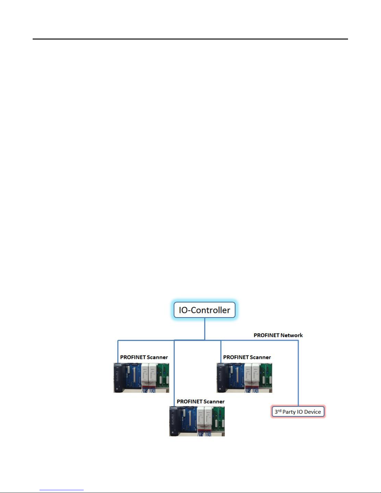
■ Add IO-Devices to the LAN. These IO-Devices can be PAC8000 PROFINET Scanner
modules or third-party IO-Devices. PAC8000 PROFINET Scanners and other types
of IO-Devices use GSDML files to describe their capabilities. The PROFINET IO
configuration tool imports these GSDML files and incorporates the devices into the
configuration.
■ Configure the parameters of the PAC8000 PROFINET Scanners and other
IO-Devices.
■ Configure the communications properties of the PROFINET IO-Controller, PAC8000
PROFINET Scanners, and other IO-Devices.
■ Add PAC8000 IO modules to the PAC8000 PROFINET Scanner..
■ Configure the parameters of the PAC8000 IO modules and other devices in the PNS.
■ When the configuration is ready, use a DCP tool to assign a name to each IO-Device
so the PROFINET IO-Controller can connect to the devices and deliver their
configuration.
■ Store the configuration data from the configuration tool to the PROFINET
IO-Controller.
Note: When the connection between IO-Controller and PNS is in progress, and if a new
configuration download initiated, first the existing connection breaks and the output
modules go into failsafe state (if configured so). Otherwise output modules hold the
last values. This output state continues till a valid output data received from IOController.
3.1.2 Configuration Tool
The configuration tool used to configure the PROFINET LAN containing the PNS module
must support PROFINET V2.3 IO Devices.
Page 33

Index
GFK-2839B PAC8000* IO PROFINET Scanner User’s Manual–September 2017 33
3.2 Adding a PAC8000 PROFINET Scanner to a LAN
Use the PROFINET IO configuration tool to add a PNS module to the LAN. This process may
include importing the PNS module’s GSDML files. If necessary for your application, change
the settings of the PNS module’s configurable parameters listed below.
3.2.1 Configuring PAC8000 PROFINET Scanner Parameters
The PROFINET IO Scanner provides 64-bits of status data and receives 16-bits of output
control data. These should be mapped to the IO-Controller’s memory.
The IO-Controller determines the operation of inputs when the PNS is unable to provide
them. This typically happens when the PNS is not powered on, connected to the network, or
there is a network or configuration issue such that the IO-Controller cannot reach the PNS.
The IO-Controller may support defaulting inputs to fixed or configurable values or holding the
last known good state of inputs until connectivity is restored (Based on controller
configuration parameters).
The PNS has a single parameter on slot 0, subslot 1 that specifies the action the PNS will
take if a fatal error occurs. By default, the PNS module LEDs blinks a fault code if a fatal error
occurs and the output modules are forced to go into failsafe state (if configured so). This can
be changed to cause the PNS to restart instead.
The network parameters of the PNS (IP Address, subnet mask, and gateway IP) should
either be configured to match the fixed parameters assigned to the PNS using a DCP Tool or
to what the IO-Controller should assign during the startup of communications between the
PNS and IO-Controller. If the network parameters assigned by the DCP tool are different from
the configuration in the IO-Controller and the IO-Controller is configured to assign them to IODevices, then when the IO-Controller assigns them as a temporary setting, the settings
previously stored from the DCP tool are lost. On a reset, the IO-Device is set to factory
default values (0.0.0.0/0.0.0.0/0.0.0.0).
The rate of data exchange is usually configured on the PNS in configuration tools. The PNS
supports update rates from 1ms to 512ms. The correct setting for each device can depend on
the dynamics of the equipment being controlled, the network loading on the PROFINET-IO
LAN, and the loading of the IO-Controller. It is possible to have better performance at 4ms or
greater periods than at 1ms, depending on the overall system requirements, design, and
loading.
3.2.1.1 Configuring PAC8000 PROFINET Scanner for PROFINET System Redundancy
The PAC8000 PNS supports PROFINET System Redundancy feature (PROFINET V2.3
Type S2 System Redundancy). This feature allows PNS to be part of a Hot-Standby (HSB)
CPU Redundancy system as shown below. In the HSB redundancy system, the two IO
controllers, based on their mutual agreement, makes primary and backup AR (application
relationship) connections with the PNS. One controller acts as a primary and the other acts
as backup. Once the connection is made, the PNS exchanges data only with the primary
controller.
In the HSB system, the CPUs/HOSTs continuously monitors the health status of connection
between the primary controller and PNS. If the CPUs finds the primary connection unreliable
at any point of time, it switches over the primary connection ownership to the backup
controller and commands PNS to recognize this change. The PNS then recognizes this
change and will immediately start the data exchange with the new primary controller
(previously backup controller).
Page 34

Contents
34 PAC8000* IO PROFINET Scanner User’s Manual–September 2017 GFK-2839B
HOSTHOST
Profinet
Controller
IOC
Profinet
Controller
IOC
Profinet
Device
NAP
IO Module
Profinet
Device
NAP
IO Module
PROFINET IO
SR-ARa
SR-ARb
The “Redundancy mode” tab in the configuration tool selects whether or not the PNS to be
redundantly controlled.
When it is configured for “HSB CPU Redundancy”, the PROFINET System Redundancy
feature in PNS gets enabled. This causes the PNS to accept redundant PROFINET SR-AR
connections (primary and backup) from the controllers.
When it is configured for “None”, the PROFINET System Redundancy feature in PNS gets
disabled. This causes PNS to accept only one AR connection from the controller (simplex
operation).
3.2.1.2 Media Redundancy Parameters
By default, the PNS is not set up for Media Redundancy. If the PNS will be a Media
Redundancy Client, select the PNS ports that will be used for Ring Port 1 and Ring Port 2,
and the MRP Domain. The MRP Domain name is used to assign MRP Clients to the media
redundancy manager (MRM) for the network ring.
Media Redundancy = None (Media redundancy Disabled).
Media Redundancy = Client (Media redundancy Enabled).
3.2.1.3 Module Parameters
Fatal Error Action
If a fatal error occurs, the PNS either blinks an error code on its LEDs and sets the modules
into fail safe state or Gets restarted based on the configuration.
Apply Failsafe = PNS blinks an error code on the LEDs
Auto Restart = PNS Restarts
Page 35

Index
GFK-2839B PAC8000* IO PROFINET Scanner User’s Manual–September 2017 35
Communication Timeout
Control application (PROFINET Controller) should toggle Heartbeat bit (refer Output Control
Register) to indicate it is alive. When there is no update to this bit for more than configured
communication timeout time, the PNS treats it as a communication/application failure and
goes to failsafe state.
0 = Disabled.
Values for communication timeout range 50 ms, 100ms, 200 ms, 500 ms, 1 Sec, 2 Sec, 5
Sec, 10 Sec, 20 Sec, 50 Sec.
SNMP Configuration
From release 2.00 onwards PNS supports SNMP protocol.
Enable SNMP Service = Enables SNMP protocol services in the PNS
Disable SNMP Service = Disables SNMP protocol services in the PNS
Page 36

Contents
36 PAC8000* IO PROFINET Scanner User’s Manual–September 2017 GFK-2839B
3.2.2 Configuring PAC8000 PROFINET Scanner Parameters
After adding PAC8000 PROFINET scanner(s) to the PROFINET IO Controller in the
programmer, their parameters must be configured. Configuration details for basic parameters
are given in the following pages.
3.2.2.1 Basic Module Parameters
The PNS parameters define how the IO-Controller scans and stores the PNS data.
Default values are provided by the module’s GSDML file.
Input Data / Output Data: The address in the IO-Controller’s reference memory for the
module’s data.
Length: The length of the input /output data is fixed and cannot be edited (Non
Configurable).
3.2.2.2 Additional Module Parameters
Additional module parameters vary, depending on the module type. Some modules have only
a few parameters. Others have several. The additional parameters that must be configured
for more complex modules are explained in the individual module documentation.
On Failsafe: When the module has outputs, this field specifies how the PNS will handle the
module’s output data if it loses communication with the IO-Controller. Select either Hold Last
State or Failsafe Value (For Analog modules) or ON/OFF (For Digital modules). This
selection has to be made for each channel in the module. If Failsafe Value is chosen, failsafe
values can be set up on a per-channel basis. If the Failsafe time out is set to ‘0’, Failsafe is
disabled.
Note: PAC8000 analog and digital modules latch their last outputs when configured for
Hold Last State and hold that value as long as field power remains on to the module.
Clear Latch: These control bits of the module clears the Latch of the selected channel. If the
channel’s Latch is enabled in the configuration and got Latched to an input, by using the
corresponding bit user can clear the Latch. As long as the Latch Bit is set to 1 the Latch on
that channel will be disabled. This control bit is available to DI modules with pulse counters
enabled.
Clear Counter: These control bits of the module clears the Counter of the selected channel. If
the channel’s Counter is enabled in the configuration and has been counting the pulses, by
using the corresponding bit user can clear the Counter. As long as the Clear Counter Bit is
set to 1 the Counting on that channel will be disabled.
3.2.2.3 Configuring the Module Parameters
Please refer to the PAC8000 IO module’s manual (8000-2/x Series Modular I/O GFA-1779)
for configuration details
Page 37

Index
GFK-2839B PAC8000* IO PROFINET Scanner User’s Manual–September 2017 37
3.3 Assigning IO-Device Names
After the PNS and other IO-Devices on the LAN have been entered into the configuration, a
Discovery and Configuration Protocol (DCP) tool must be used to assign a name to each IODevice. The Name of each device on the LAN must match the configuration. This step is
required before downloading the configuration from the PROFINET IO-Controller, otherwise
the PROFINET IO-Controller will be unable to connect to the devices and deliver their
configuration.
The DCP tool must be connected to PROFINET IO LAN, either through the PROFINET
IO-Controller or directly to the LAN depending on whether it operates through the
IO-Controller or directly to IO-Devices.
3.4 Clearing the IO-Controller Configuration
The PAC8000 PROFINET Scanner reacts to clearing the PROFINET IO-Controller as a loss
of connectivity, and takes appropriate actions such as setting outputs to the failsafe state.
Clearing the IO-Controller does not typically cause a clearing action on all connected
IO-Devices.
3.5 Replacing PAC8000 PROFINET Scanner Hardware
If a PNS module needs to be replaced for any reason, the steps to commission a new
hardware module are below.
If the replacement PNS module has no assigned name (the CONNECT LED blinks slowly),
the network cabling can be plugged back in and the name assigned over the IO network. If
there is a possibility of duplicate names existing on the network due to a pre-existing IODevice name assigned in the replacement module, the IO-Device Name should be assigned
before inserting it into a working IO network. The IO-Device Name and IP Address settings
can be updated offline (for example, in an office setting).
1. Power down the PNS.
2. Remove network cabling from the module.
3. Remove the old module.
4. Insert the new PNS module.
5. Connect network cabling to the new PNS module.
6. Apply power to the new PNS module hardware.
7. Optional: Assign IP address settings to the new PNS module using the DCP tool if
this was not done offline. The IO-Controller will update any IP address settings
automatically when it connects if this step is skipped.
8. If an IO-Device Name was not assigned to the new PNS module, assign it now.
Page 38

Contents
38 PAC8000* IO PROFINET Scanner User’s Manual–September 2017 GFK-2839B
Chapter 4. Diagnostics
This chapter describes:
■ PNS Status and Control Data
o Output Control Register
o Input Status Registers
o PNS Status register
o PNS Network port status register
o PNS Power status register
o PNS Module health status register
■ Error Handling
o Fatal Error Handling
o PROFINET Alarms
o PROFINET Module Loss, Add & Mismatch Faults
4.1 PNS Status and Control Data
The PAC8000 PROFINET Scanner provides 64 bits of input status data and receives 16 bits
of output control data. The application program in the IO-Controller system can monitor the
input status bits and can perform some control operations using the output control bits. This
data is associated with slot 0 submodule 1 in the configuration.
4.1.1 Output Control Register
The PNS’s 16 bits of output control data can be used to trigger module actions.
Output
Bits
Name
Description
1 (LSB)
Reset
0 to 1 transition resets the PNS.
1 to 0 transition has no effect.
2
Set Failsafe
0 to 1 transition sets the PNS to failsafe state.
1 to 0 transition has no effect.
3
Clear Failsafe
0 to 1 transition commands the PNS to clear failsafe state
1 to 0 transition has no effect.
4
Heartbeat Enable
1 = Enable Heartbeat feature.
0 = Disable Heartbeat feature.
5
Heartbeat
Remote application (host) should toggle this bit to indicate it is
alive. When there is no update to this bit for more than
configured communication timeout, the PNS treats it as a
communication/application failure and goes to failsafe state.
Applicable only when “Heartbeat Enable” in output control
register is ‘1’.
6 – 16
Reserved
Page 39

Index
GFK-2839B PAC8000* IO PROFINET Scanner User’s Manual–September 2017 39
4.1.2 Input Status Registers
Byte
Register
Description
1
PNS Status Register (PSR)
Device/Scanner Status
2
3
PNS Network Port Status Register (PNSR)
Network Status
4
PNS Power Status Register (PPSR)
Power Status
5
Module Health Status Register (MHSR)
IO module Health Status
6
7
8
4.1.2.1 PNS Status Register (PSR)
The PSR provides 16 bits of information about the PNS module. All status bits are active
high.
Status
Bits
Name
Description
1 (LSB)
PNS OK
1 = PAC8000 PNS is up and running
0 = Unrecoverable fault detected during power up
2
PNS Fault
1 = Alarm generated by PNS
0 = All alarms are cleared.
3
PNS Failsafe
1 = PNS is in failsafe state
0 = PNS is not in failsafe state
4
Heartbeat Echo
IO-Controller sets “Heartbeat” in output control register and
when PNS receives it, it echoes back that value in
“Heartbeat Echo”. Echoing before the configured
communication timeout confirms communication between
IO-Controller and PNS is healthy.
5
Heartbeat Status
1 = Heartbeat failure
0 = Heartbeat OK
6-16
Reserved
4.1.2.2 PNS Network Port Status Register (PNSR)
The PNSR provides 8 bits of information about the network. All status bits are active high.
Status
Bits
Name
Description
1(LSB)
Port 1 Link Status
1 = Link detected at port 1 of PNS
0 = Link failure at port 1 of PNS
2
Port 2 Link Status
1 = Link detected at port 2 of PNS
0 = Link failure at port 2 of PNS
3-8
Reserved
Reserved for future use
Page 40

Contents
40 PAC8000* IO PROFINET Scanner User’s Manual–September 2017 GFK-2839B
4.1.2.3 PNS Power Status Register (PPSR)
The PPSR provides 8 bits of information about the power supply. All status bits are active
high.
Status
Bits
Name
Description
1 (LSB)
Power Line 1 Status
1 = Power supply is healthy
0 = Power supply failed
2
Power Line 2 Status
1 = Power supply healthy
0 = Power supply failed
3
Power Line 3 Status
1 = Power supply is healthy
0 = Power supply failed
4
Power Line 4 Status
1 = Power supply is healthy
0 = Power supply failed
5
Power Line 5 Status
1 = Power supply is healthy
0 = Power supply failed
6
Power Line 6 Status
1 = Power supply is healthy
0 = Power supply failed
7-8
Reserved
Reserved for future use
4.1.2.4 Module Health Status Register (MHSR)
The MHSR provides 32 bits of information about the module’s health. All status bits are active
high.
Status
Bits
Name
Description
1(LSB)
Module in slot 1
1 = Module Healthy
0 = Module not Healthy
2
Module in slot 2
1 = Module Healthy
0 = Module not Healthy
3
Module in slot 3
1 = Module Healthy
0 = Module not Healthy
4
Module in slot 4
1 = Module Healthy
0 = Module not Healthy
…
…
32
Module in slot 32
1 = Module Healthy
0 = Module not Healthy
Page 41

Index
GFK-2839B PAC8000* IO PROFINET Scanner User’s Manual–September 2017 41
4.2 Error Handling
The PNS has two error-handling methods: fatal error handling and PROFINET diagnostics.
4.2.1 Fatal Error Handling
Any failures that occur during powerup or firmware update mode are considered fatal errors.
This includes faults detected on non-critical devices such as the USB port. After successful
power-up of the PNS, only catastrophic errors are treated as fatal.
If a fatal error occurs, the PNS either blinks an error code on its LEDs and sets the modules
into fail safe state (If the modules are configured for failsafe), or restarts automatically,
depending on its configured Fatal Error Action.
When the PNS detects a catastrophic failure it tries to save diagnostic information to nonvolatile storage. This information overwrites any previous diagnostic information in storage.
Only information about the most recent fatal error is retained. This information is available on
future power cycles to be retrieved and sent to GE Intelligent Platforms for analysis.
While diagnostic information is being saved, the PNS blinks its OK LED. The PNS disables
Ethernet and USB communications, so communication with the module is not possible. If the
PNS cannot save the diagnostic information it is considered a failed Save attempt.
After the attempt to store the information has completed (whether it succeeded or failed), the
module either blinks an error code or restarts, depending on how it is configured.
4.2.1.1 Automatic Restart
If the PNS is configured to automatically restart after a fatal error, on the next successful
power-up, a diagnosis alarm is generated to indicate the PNS reset. This alarm turns the
Fault LED on and persists until the PNS is power-cycled. There is no way to clear this fault
other than a second successful restart.
A persistent fatal error that occurs after the PNS has successfully powered up can cause the
module to continually reset itself.
4.2.1.2 Apply Failsafe operation
If the PNS is configured to put the PNS into failsafe when a fatal errors, the PNS goes into
failsafe state. All output modules will also go into failsafe state (if they are configured so).
Page 42

Contents
42 PAC8000* IO PROFINET Scanner User’s Manual–September 2017 GFK-2839B
4.2.2 PROFINET Diagnostics
The PNS reports its own non-fatal errors and errors on modules using PROFINET Diagnosis
or PROFINET Pull/Plug alarms.
4.2.2.1 PROFINET Diagnosis Alarms
Diagnosis Alarms indicate any fault conditions other than a module add, loss, or mismatch
that a PAC8000 PROFINET Scanner needs to communicate to the PROFINET IO-Controller.
Most faults generate Diagnosis alarms. Situations that do not send a PROFINET Diagnosis
are covered in a later section.
When the PAC8000 PROFINET Scanner detects a fault condition, it sends a Diagnosis alarm
to the IO-Controller. If there is an Application Relationship (AR) currently active, the PAC8000
PNS sends the Diagnosis alarm over that AR. Otherwise, the alarm is placed in diagnosis
memory in the PNS to be read later, and no alarm is sent. The Scanner’s FAULT LED is ON
and the FAULT status bit (see bit definitions of PNS status register mentioned earlier in this
chapter) is set to 1. An alarm is not generated on subsequent connections.
The PNS automatically clears (and sends Diagnosis Disappears alarms for) these diagnosis
faults after the fault condition has been corrected. If no additional conditions exist in memory,
the FAULT LED is turned OFF and the FAULT status bit is set to 0.
The table on the next page lists the faults reported to the IO-Controller. The PAC8000 PNS
generates all of its application faults as channel diagnosis faults. The AlarmType is Diagnosis
Appears or Diagnosis Disappears. The left column lists the Channel Error Type in
PROFINET.
Page 43

Index
GFK-2839B PAC8000* IO PROFINET Scanner User’s Manual–September 2017 43
PNS Diagnosis Alarms
Channel
Error
Type
Diagnosis Alarm
Type
Module
or
Channe
l Error
Cause
Fault Text
Recommendation
6
Channel Diagnosis
Appears / Disappears:
Line Break
Channel
Open Wire/Line break
detected on a channel
Line Break
Verify wiring of the channel
16
Channel Diagnosis
Appears/Disappears
Module
Module not Configured
The module rejected
the configuration
parameters.
Verify the configuration
parameters against their
allowable ranges for the
operation
17
Channel Diagnosis
Appears/Disappears
Module
Loss of User Power
The module has lost
field power.
Check power supplies and
wiring
256
Channel Diagnosis
Appears/Disappears
Channel
Line Fault detected on
a channel.
Line Fault Detected
Verify wiring of the channel
257
Channel Diagnosis
Appears/Disappears
Channel
Channel value is above
configured Hi Alarm
High alarm detected
Bring process value on the
channel below configured high
alarm level
258
Channel Diagnosis
Appears/Disappears
Channel
Channel value is above
configured Hi-Hi Alarm
High High alarm
detected
Bring process value below
configured high high alarm
level
259
Channel Diagnosis
Appears/Disappears
Channel
Channel value is below
configured Low Alarm
Low alarm detected
Bring process value above
configured low alarm level
260
Channel Diagnosis
Appears/Disappears
Channel
Channel value is above
configured Lo-Lo Alarm
Low Low alarm
detected
Bring process value above
configured low low alarm
level
261
Channel Diagnosis
Appears/Disappears
Channel
Channel detected fault
in ADC
ADC Error Detected
Check the Bused Field Power
of the IO carrier . If it is ok,
contact GE-IP support team
for help.
262
Channel Diagnosis
Appears/Disappears
Channel
Channel configuration
has invalid alarm
settings. This fault
occurs after
configuration download,
when following
condition is NOT met
Lo-Lo alarm <= Lo
Alarm < Hi Alarm <= HiHi Alarm
Parameterization
error in alarm setting
In configuration tool adjust the
alarm settings so that they
meet the condition Lo-Lo
alarm <= Lo Alarm < Hi Alarm
<= Hi-Hi Alarm and download
the configuration again.
Page 44

Contents
44 PAC8000* IO PROFINET Scanner User’s Manual–September 2017 GFK-2839B
Channel
Error
Type
Diagnosis Alarm
Type
Module
or
Channe
l Error
Cause
Fault Text
Recommendation
263
Channel Diagnosis
Appears/Disappears
Channel
Channel configuration
has invalid pulse
settings. This fault
occurs after
configuration download,
when following
condition is NOT met
(1) If Operation mode is
Single Pulse (Static),
failsafe value should be
OFF, pulse period
should be 0
(2) If Operation mode is
Continuous Pulse
(Static), failsafe value
should be OFF/Hold
Last State, pulse period
>= 6ms and pulse
period > on time
Parameterization
error in failsafe
value/Pulse
period/Pulse on time
In the configuration tool, set
the parameters properly and
download the configuration
again.
264
Channel Diagnosis
Appears/Disappears
Channel
Channel configuration
has invalid settings.
This fault occurs after
configuration download,
when any of the
parameters are out of
expected range.
TI Alarms/Dead zone
range fault
In the configuration tool, set
the parameters properly and
download the configuration
again.
268
Channel Diagnosis
Appears/Disappears
Channel
Open Sensor detected
on a channel
Open circuit fault for
the sensor on channel
Verify wiring of the channel
269
Channel Diagnosis
Appears/Disappears
Channel
Cold Junction
Compensation Fault
detected
Cold Junction
Compensation Fault
Check if either of the (two)
cold junction compensation
elements have gone open
circuit or out of range
270
Channel Diagnosis
Appears/Disappears
Channel
The Dynamic pulse on
time or period is not in
range. Or difference
between Period and On
Time is less than 5ms
The Dynamic pulse
on time or period is
not in range. Or
difference between
Period and On Time
is less than 5ms
Check if the Dynamic pulse on
time or period is not in range
(valid range Period: 10 –
60000, and 65530, 65531,
65532, 65533, 65534, 65535,
On Time : 5 - 60000). Period
must be at least 5 ms greater
than On Time
271
Channel Diagnosis
Appears/Disappears
Channel
The Thermocouple
compensation fault
The Thermocouple
compensation fault
Check if the Thermocouple
compensation is selected
correctly and values are within
range
272
Channel Diagnosis
Appears/Disappears
Channel
The Thermocouple HH,
H, L, LL fault
The Thermocouple /
RTD Parameterization
error.
Verify LL alarm <= L Alarm
< H Alarm <= HH Alarm.
Verify alarms between Min
and Max temp. Deadband and
Deadzone are between Min +
Max temp
Page 45

Index
GFK-2839B PAC8000* IO PROFINET Scanner User’s Manual–September 2017 45
Channel
Error
Type
Diagnosis Alarm
Type
Module
or
Channe
l Error
Cause
Fault Text
Recommendation
273
Channel Diagnosis
Appears/Disappears
Channel
Channel fault
Channel fault
Verify Channel fault
274
Channel Diagnosis
Appears/Disappears
Channel
Secondary data fault
Secondary data fault
Verify Secondary data fault
4096
Channel Diagnosis
Appears/Disappears
Module
Module is in fault state
Module Fault
Detected
Contact GE-IP support team
4097
Channel Diagnosis
Appears/Disappears
Module
Parameterization error
due to Configurator or
Corrupted GSDML file
used for configuration
Module fatal
parameterization error
Verify that Configuration tool
is working properly and
GSDML file is not modified or
corrupted.
4098
Channel Diagnosis
Appears/Disappears
Module
Module not in a position
to accept the
configuration.
Module rejected
configuration
Power cycle the module. If the
problem still persists may be
module replacement required.
4099
Channel Diagnosis
Appears/Disappears
Module
A fatal error reset
happened (when
PNS is configured to
automatically restart
after a fatal error)
Auto-Restart event
occurred
Contact GE-IP support team
4.2.3 Clearing Faults on PAC8000 Modules
The PAC8000 PROFINET Scanner clears alarms as soon as the underlying condition returns
to normal.
Page 46

Contents
46 PAC8000* IO PROFINET Scanner User’s Manual–September 2017 GFK-2839B
4.2.4 PROFINET Module Loss, Add and Mismatch Faults
The PAC8000 PROFINET Scanner uses standard PROFINET Pull/Plug alarms to indicate
differences between the configured modules and the actual modules present in the PNS.
■ If a module is configured, but is not present or not operating correctly, the PNS
indicates the module as removed via a Pull Alarm.
■ If a different IO module is hot-inserted than configured while an Application
Relationship is active, the PAC8000 PROFINET Scanner reports the mismatch using
a Plug Wrong Submodule alarm.
■ PNS does not generate alarms for an un-configured slots. The module is ignored by
the PNS and remains at its module defaults.
■ When a configured IO module is plugged into a configured slot, PNS sends a Plug
Alarm.
■ Configuration related alarms are generated when user configuration is not valid. For
each invalid configuration of a IO module, an alarm is generated. If all modules have
invalid configuration, 32 alarms will be generated. Note that only one alarm per IO
module is generated (even though more than one invalid configuration exists on a
module). If an IO module has an invalid configuration, an alarm is generated and that
IO module will not be put under IO scan.
Page 47

Index
GFK-2839B PAC8000* IO PROFINET Scanner User’s Manual–September 2017 47
Chapter 5. PROFINET Specifications
Release 2.00 of the PAC8000 PROFINET Scanner supports PROFINET v2.3 Class A
IO-Device with the clarifications listed below. For version-specific updates, refer to the
Important Product Information document provided with your module.
5.1 PROFINET Protocol Support
RTC – Real time Cyclic Protocol: RT_CLASS_1 & RT_CLASS_2
RTA – Real time Acyclic Protocol
DCP – Discovery and Configuration Protocol
CL-RPC – Connectionless Remote Procedure Call
LLDP – Link Layer Discovery Protocol – transmission only
MRP – Client role only (Manager role not supported)
PTCP – Precision Transparent Clock Protocol – Line delay measurement only
5.2 Technical Data
API:
Single API (0) used.
Number of Application Relations
supported:
1 (Additional Supervisor-DA-AR allowed)
Number of System Redundancy
Application Relations (SR-AR) sets
supported
1
Maximum length of cyclic input
data:
1440 bytes
Maximum length of output data:
1440 bytes
Alarm Types:
Pull, Plug, PlugWrong
DCP:
Get/Set/Identify supported. Only All and Name Of
Station filters supported
Identification & Maintenance:
I&M0 only
Context Management:
by CL-RPC
Minimum cycle time:
1ms
Ethernet rate:
100 Mbit/s full duplex with auto-negotiation
Page 48

Contents
48 PAC8000* IO PROFINET Scanner User’s Manual–September 2017 GFK-2839B
5.3 Limitations
The following features are not supported.
RT over UDP
IRT
Multicast communication
DHCP
DCP Hello service
DNS (Domain Name Service protocol)
FastStartUp
Supervisor-AR. Note: Supervisor-DA-AR is supported. (Device Access supported)
Optical power diagnostics (IC200PNS002)
CBA
Substitute Data
Only one Input-CR and one Output-CR are supported.
8515-BI-PN, 8
8516-BI-PN, 8
8752-CA-NS, 8
Automatic Restart
PAC8000 PROFINET Scanner, 41
Bussed field power supply(BFP)
monitoring, 12
Cables
clearance for, 21
Carriers
IO, 17
PNS, 17
Configuration
clearing, 37
getting started, 37
overview, 31
Controls and Indicators, 10
DIN rail, 23
Discovery and Configuration Protocol
(DCP), 37
Error Handling
PAC8000 PROFINET Scanner, 41
Ethernet Network Ports, 13
Fatal Error Blink Pattern, 28
Fatal error handling, 41
Faults
clearing, 44
module loss, add and mismatch, 45
Firmware Update Mode Blink Patterns, 28
Firmware updates
PAC8000 modules in remote node, 29
PAC8000 PROFINET Scanner, 29
Grounding, 25
Hazardous Locations, 22
Installation, 19
cables, 21
PAC8000 PROFINET Scanner, 19
replacing PROFINET Scanner
hardware, 37
IP addresses, 9
LEDs, 10
blink patterns, 28
operation, 27
MAC Addresses, 9
Media Redundancy Protocol (MRP), 16
Module Identification LED Pattern, 28
Modules, carriers, and power supplies, 17
Operating Temperature Range, 9
Output Control Bits
PAC8000 PROFINET Scanner, 38
PAC8000 Module Parameters
configuration, 36
PAC8000 PROFINET Scanner
Page 49

Index
GFK-2839B PAC8000* IO PROFINET Scanner User’s Manual–September 2017 49
adding to a LAN, 33
LEDs, 10
overview, 7
parameters, 33
specifications, 9
Port Connectors, 9
Power Requirements, 9
Power supply modules, 11
connecting, 26
requirements, 18
Power-up and Restart
PAC8000 PROFINET Scanner, 26
PROFINET Diagnostics, 42
PROFINET support, 9, 46
Replacing PROFINET Scanner hardware,
37
RoHS Compliance, 9
Status and Control Bits, 9
Status and Control Data
PAC8000 PROFINET Scanner, 38
Technical Support, 3
Thermal requirements
clearance for, 19
USB port, 16
driver, 30
Page 50

GE Intelligent Platforms
Information Centers
Headquarters:
1-800-433-2682 or 1-434-978-5100
Global regional phone numbers
are available on our web site
www.ge-ip.com
Additional Resources
For more information, please visit the GE
Intelligent Platforms web site:
www.ge-ip.com
©2013 GE Intelligent Platforms, Inc. All Rights Reserved
*Trademark of GE Intelligent Platforms, Inc.
All other brands or names are property of their respective holders.
GFK-2839B
 Loading...