

Page 1
GE Energy Connections
Grid Solutions
MiCOM P40 Agile
P741, P742, P743
Technical Manual
Busbar Differential Protection Relay
Hardware version: J and K
Publication reference: P74x/EN M/Na7
Software version: 51
Page 2

Page 3

CONTENTS
TD
IT
ST
GS
OP
AP
PL
MR
FD
CM
VH
TS
SC
SG
IN
MT
Safety Section
Section 1 I
Section 2 T
Section 3 G
Section 4 S
Section 5 O
on 6 Application Notes P74x/EN AP/Na7
Secti
Section 7 P
Section 8 M
ntroduction P74x/EN IT/Na7
echnical Data P74x/EN TD/Na7
etting Started P74x/EN GS/Na7
ettings P74x/EN ST/Na7
peration P74x/EN OP/Na7
rogrammable Logic P74x/EN PL/Na7
easurements and Recording P74x/EN MR/Na7
Section 9 F
Section 10 C
Section 11 M
Section 12 T
Section 13 S
Section 14 S
Section 15 In
Section 16 F
irmware Design P74x/EN FD/Na7
ommissioning P74x/EN CM/Na7
aintenance P74x/EN MT/Na7
roubleshooting P74x/EN TS/Na7
CADA Communications P74x/EN SC/Na7
ymbols and Glossary P74xEN SG/Na7
stallation P74x/EN IN/Na7
irmware and Service Manual Version History P74xEN VH/Na7
Appendix A
Page 4

Page 5

Introduction
a7
MiCOM P74
IT
1, P742, P743
P74x/EN IT/N
INTRODUCTION
Hardware Suffix: J and K
Software Version: 51
Page 6

P74
x/EN IT/Na7
Introduction
MiCOM P741, P742, P743
Page 7

Introduction
a7
MiCOM P741, P742, P743
1
IT
(IT) 1-
P74x/EN IT/N
CONTENTS
1. DOCUMENTATION STRUCTURE 3
2. INTRODUCTION TO MiCOM 5
3. PRODUCT SCOPE 6
3.1 Functional overview 6
3.2 Ordering options 8
FIGURES
FIGURE 1: FUNCTIONAL DIAGRAM 7
Page 8

P74
x/EN IT/Na7
Introduction
(IT) 1
MiCOM P741, P742, P743
IT
-2
Page 9

Introduction
a7
MiCOM P741, P742, P743
3
IT
(IT) 1-
1. DOCUMENTATION STRUCTURE
The manual provides a f unctional and technical description of the MiCOM protection relay
and a comprehensive set of instructions for the relay’s use and application.
The section contents are summarized below:
P74x/EN IT Introduction
A guide to the MiCOM range of relays and the documentation structure. General safety
aspects of handling Electronic Equipment is discussed with particular reference to relay
safety symbols. Also a general functional overview of the relay and brief application
summary is given.
P74x/EN TD Technical Data
Technical data inc luding s ettin g ran ges, accurac y lim its, r ecommended operating condit ions ,
ratings and perform ance data. C omplianc e with n orms and internat ional stand ards is quoted
where appropriate.
P74x /EN GS Getting Started
A guide to the different us er interf aces of the protec tion rela y descr ibing ho w to st art using it .
This section provides detailed information regarding the communication interfaces of the
relay, including a detailed description of how to access the sett ings database stored with in
the relay.
P74x/EN IT/N
P74x /EN ST Settings
List of all relay settings, including ranges, step sizes and defaults, together with a brief
explanation of each setting.
P74x /EN OP Operation
A comprehensive and detailed functional description of all protection and non-protection
functions.
P74x /E N AP Application Notes
This section includes a description of common power system applications of the relay,
calculation of suitabl e s etti n gs , some typical worked examples, and how to apply the settings
to the relay.
P74x /EN PL Programmable Logic
Overview of the programmable scheme logic and a description of each logical node. This
section includes the factory default (PSL) and an explanation of typical applications.
P74x /EN MR Measurements and Recording
Detailed description of the relays recording and measurements functions including the
configuration of the event and disturbance recorder and measurement functions.
P74x /EN FD Firmware Design
Overview of the operation of the relay’s hardware and software. This section includes
information on the self-checking features and diagnostics of the relay.
P74x /EN CM Commissioning
Instructions on how to commission the relay, comprising checks on the calibration and
functionality of the relay.
P74x /EN MT Maintenance
A general maintenance policy for the relay is outlined.
P74x /EN TS Troubleshooting
Advice on how to r ecognize f ailure modes and the re commended co urse of act ion. Includes
guidance on who in General Electric to contact for advice.
Page 10

P74
x/EN IT/Na7
Introduction
(IT) 1
MiCOM P741, P742, P743
IT
-4
P74x /EN SC SCADA Communications
This section provides an overview regarding the SCADA communication interfaces of the
relay. Detailed protocol mappings, semantics, profiles and interoperability tables are not
provided within this manual. Separate documents are available per protocol, available for
download from our website.
P74x /EN SG Symbols and Glossary
List of common technical abbreviations found within the product documentation.
P74x /EN IN Installation
Recommendations on u npacking, handling, inspecti on and storage of the rela y. A guide to
the mechanical and electrical installation of the relay is provided, incorporating earthing
recommendations. All external wiring connections to the relay are indicated.
P74x /EN VH Firmware and Service Manual Version History
History of all hardware and software releases for the product.
Page 11

Introduction
a7
MiCOM P741, P742, P743
5
IT
(IT) 1-
2. INTRODUCTION TO MiCOM
MiCOM is a comprehens ive solut ion capab le of meet ing all electr icit y suppl y requirem ents . It
comprises a range of components, systems and services from General Electric.
Central to the MiCOM concept is flexibility.
MiCOM provides the ability to define an application solution and, through extensive
communication capabilities, integrate it with your power supply control system.
The components within MiCOM are:
− P range protection relays;
− C range control products;
− M range measurement products for accurate metering and monitoring;
− S range versatile PC support and substation control packages.
MiCOM products include extensive facilities for recording information on the state and
behaviour of the p ower system using dis turbance and fault recor ds. They can also prov ide
measurements of the system at regular intervals to a control centre enabling remote
monitoring and control to take place.
P74x/EN IT/N
For up-to-date inform ation on an y MiCOM pro duc t, vis it our webs ite:
www.gegridsolutions.com
Page 12
P74
x/EN IT/Na7
Introduction
(IT) 1
MiCOM P741, P742, P743
IT
•
•
•
•
•
•
•
•
• •
• •
• • •
• • •
• •
• • •
• • •
• • •
• - •
-6
3. PRODUCT SCOPE
The P74x differential busbar protection relays have been designed for the protection of a
wide range of subs tation b usbars f rom distr ibution t o transm ission vo ltage le vels. The r ela ys
include a comprehens ive range of non-pro tection features to a id with system dia gnosis and
fault analysis. The P74x offers integral b iased diff erential bus bar, br eak er failure, dead zo ne,
overcurrent and earth-fault protection and is suitable for application on solidly grounded,
impedance grounded, Petersen coil grounded and isolated systems. The relays are
especially suitable where a complete scheme solution is required.
The scheme comprises of three relays:
• The P741 (Central Unit),
• The P742 and P743 (Peripheral Units).
Which, together with the topology configuration software and the dynamic synoptic
monitoring tool, allow full flexibility for all configurations.
3.1 Functional overview
The P74x Busbar protection contains a wide variety of protection func tions. The protection
features are summarized below:
Protection Functions Overview
ANSI IEC 61850 Function P741 P742 P743
87BB / P PhsPDIF Phase segregated biased current differential high speed and
87CZ / P CzPPDIF Check Zone segregated biased phase current differential
87BB / N NeuPDIF Sensitive earth fault bias current controlled busbar protection
87 CZ/ N CzNPDIF Check Zone segregated biased earth current controlled
50 / 51 / P OcpPTOC Phase overcurrent protection (2 stages) 50 / 51 / N EfmPTOC Eart h overc urrent protecti on (2 st ages) -
50ST / P DzpPhsPTOC Dead zone phase protection (short zone between CTs and
50ST / N DzpEfmPTOC Dead zone earth protection (short zone between CTs and
CTS Current transformer supervision
50BF RBRF Breaker failure protection (LBB)
ISL Isolator discrepancy alarm Fibre optic signalling channel
OptGGIO Digital inputs (according to product) * 8 8/16 16/24
RlyGGIO Output relays (according to product) * 8 8/12 12/16/20
High Break relays (according to product) * 4 4/8
Virtual Digital inputs (via fibre communication) 16 16 16
Virtual Output relays (via fibre communication) 16 16 16
Front communication port (RS232)
Rear communication port (Kbus/EIA(RS)485)
Second Rear communication port (Kbus/EIA(RS)485)
Rear communication port (Ethernet) * Option - Option
Time synchronisation port (IRIG-B) * Option Via CU Via CU
Redundant Ethernet port Option - Option
FnkGGIO Function keys 10 - 10
LedGGIO Programmable tri-colour LEDs 18 - 18
* Refer to the data sheet for model selection
delayed busbar protection
high speed and delayed busbar protection
busbar protection
open CBs)
open CBs)
-
-
- -
- -
- -
- -
Page 13
Introduction
a7
MiCOM P741, P742, P743
7
IT
(IT) 1-
The P74x supports the following relay management functions in addition to the functions
illustrated above.
• Trip circuit and coil supervision
• 4 Alternative setting groups
• Programmable function keys (P741 and P743)
• Control inputs
• Programmable scheme logic
• Programmable allocation of digital inputs and outputs
• Sequence of event recording
• Comprehensive disturbance recording (waveform capture)
• Fully customizable menu texts
• Multi-level password protection
• Power-up diagnostics and continuous self-monitoring of relay
P74x/EN IT/N
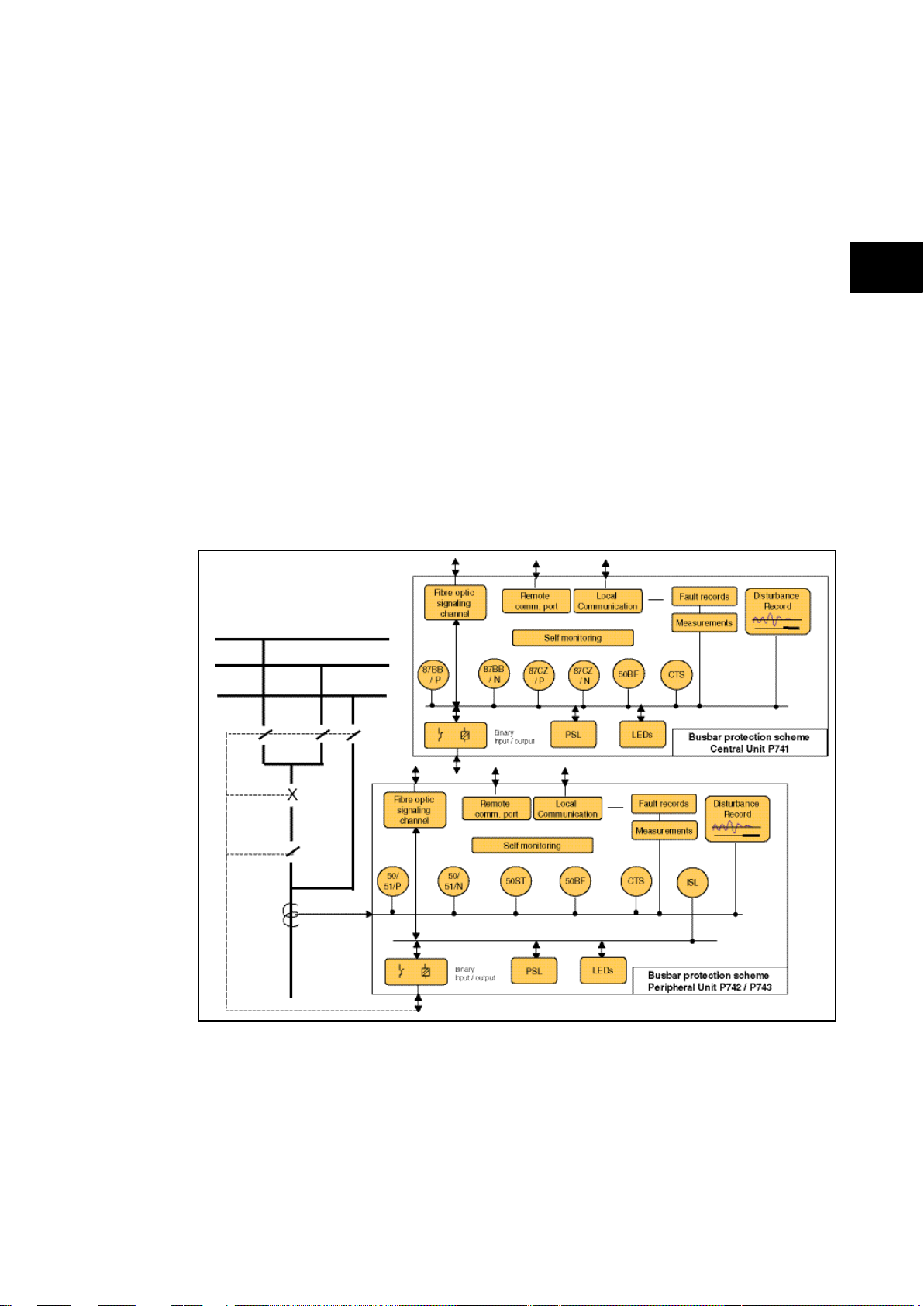
Application overview
FIGURE 1: FUNCTIONAL DIAGRAM
Page 14
P74
x/EN IT/Na7
Introduction
(IT) 1
MiCOM P741, P742, P743
IT
Information Required wit h O rder
Variants
P741 Bus bar P rot ect ion Rel ay P741
Vx Aux Rating
24 - 48 Vdc 7
48 - 125 Vdc (40 - 100 V ac ) 8
110 - 250 Vdc (100 - 240 V ac ) 9
Communication Boa rds
1 communic ation board (1 to 4 Peripheral Unit) 1
2 communic ation board (to 8 Peripheral Unit) 2
3 communic ation board (to 12 Peripheral Unit) 3
4 communic ation board (to 16 Peripheral Unit) 4
5 communic ation board (to 20 Peripheral Unit) 5
6 communic ation board (to 24 Peripheral Unit) 6
7 communic ation board ( to 28 Peripheral Unit) 7
Hardware Options
St andard - None 1
IRIG-B Only (m odulated) 2
IRIG-B (Demodulated) C
Et hernet (100 M bi t s/s) wit hout IRIG-B 6
Et hernet (100M bi t /s) pl us IRIG-B (Modulat ed) A
Et hernet (100M bi t /s) pl us IRIG-B (Un-modulated) B
2nd Rear Port & Int erM iCOM E
2nd Rear Port & Int erM iCOM & IRIG-B (Modulat ed) F
Redundant Ethernet S el f-Healing Ri ng, 2 m ul ti-mode fibre port s + M odul at ed IRIG-B G
Redundant Ethernet S el f-Healing Ri ng, 2 m ul ti-mode fibre port s + Un-modul at ed IRIG-B H
Redundant Ethernet RS TP, 2 m ul ti-mode fibre port s + M odul ated IRIG-B J
Redundant Ethernet RS TP, 2 m ul ti-mode fibre port s + Un-m odul at ed IRIG-B K
Redundant Ethernet Dual-Hom i ng S tar, 2 m ul t i -m ode fibre port s + M odul ated IRIG-B L
Redundant Ethernet Dual-Hom i ng S tar, 2 m ul t i -m ode fibre port s + Un-m odulated IRIG-B M
Redundant Ethernet P RP /HSR, 2 fibre port s + M odul ated IRIG-B N
Redundant Ethernet P RP /HSR, 2 fibre port s + Unm odul at ed IRIG-B P
Product Specific
Fixed A
Protocol Options
K-Bus/Courier
IEC60870-5-103 (Via K ITZ274)
Courier (K-Bus), IEC60870-5-103 via KITZ274 (Supplied as Courier. KITZ274 to be ordered)
Addit i onal IE C61850
Mounting
Panel M ounting, with harsh environment coati ng M
Language
Mult i l i ngual - E ngl i sh, F renc h, German, Spanis h 0
Mult i l i ngual - E ngl i sh, F renc h, German, Russi an 5
Sof twa re Issue
Unless specified t he l atest version will be del i vered **
Customisation
Default 0
Cust om er s pecific A
Central Net work s Version 5
Design Suffix
Order Number
1
6
-8
3.2 Ordering options Information Required with Order
Page 15
Introduction
a7
MiCOM P741, P742, P743
9
IT
Information Required with Order
Variants
P742 Busbar P rot ect i on P eri pheral Uni t (40TE) P742
Vx Aux Rating
24 - 54Vdc 7
48 - 125Vdc (40 - 100V ac) 8
110 - 250Vdc (100 - 240V ac) 9
Hardw a re Options
W i t hout CT Input 0
W i t h In = 1/ 5A CT Input 1
Hardw a re Options
St andard - None 1
Product Specific
8 Relay s O ut puts and 16 St at us Inputs A
8 Relay s O ut puts , 4 High B reak and 8 S t atus Input s B
Protocol Options
K-Bus/Courier
IEC60870-5-103 (Via K ITZ274)
Mounting
Flush P anel Mount ing, with Harsh Environment Coating M
Language
Multil i ngual - E ngl i sh, French, Germ an, S panish 0
Multil i ngual - E ngl i sh, French, Germ an, Rus s i an 5
Softw are Issue
Unles s specified t he l ates t versi on wil l be del i vered **
Customisation
Default 0
Cust om er spec i fic A
Central Net work s V ersion 5
Design Suffix
Order Number
1
(IT) 1-
P74x/EN IT/N
Page 16
P74
x/EN IT/Na7
Introduction
(IT) 1
MiCOM P741, P742, P743
IT
Information Required wit h O rder
Variants
P743 Busbar P rotec t i on Peripheral Unit (60TE) P743
Vx Aux Rating
24 - 54Vdc 7
48 - 125Vdc (40 - 100V ac) 8
110 - 250Vdc (100 - 240V ac)
9
Hardware Options
Wi thout CT Input 0
Wi th In = 1/ 5A CT Input 1
IEC 61850-9-2LE Sam pl ed Analogue V al ues Ethernet board *
C
Hardware Options
St andard - None 1
Et hernet (100 M bi t s/ s) without IRIG-B
6
2nd Rear Port & Int erM i COM & IRIG-B (Modul ated)
E
Redundant Ethernet Self-Healing Ring, 2 mul t i -m ode fibre port s + M odul ated IRIG-B G
Redundant Ethernet Self-Healing Ring, 2 mul t i -m ode fibre port s + Un-m odul at ed IRIG-B
H
Redundant Ethernet RS TP, 2 multi-m ode fibre port s + Modul ated IRIG-B J
Redundant Ethernet RS TP, 2 multi-m ode fibre port s + Un-modulated IRIG-B
K
Redundant Ethernet Dual -Homi ng S tar, 2 m ul ti-mode fibre ports + Modul at ed IRIG-B
L
Redundant Ethernet Dual -Homi ng S tar, 2 m ul ti-mode fibre ports + Un-modulated IRIG-B M
Redundant Ethernet PRP/ HS R, 2 fibre ports + Modul ated IRIG-B
N
Redundant Ethernet PRP/ HS R, 2 fibre ports + Unmodul at ed IRIG-B
P
Product Specific
16 Relays Out put s and 24 S t atus Inputs ** A
16 Relays Out put s, 4 High Break and 16 Status Inputs B
8 Relays Out put s, 4 High Break and 24 Status Inputs C
8 Relays Out put s, 8 High Break and 16 Status Inputs D
Protocol Options
K-Bus/Courier
IEC60870-5-103 (Via K ITZ274)
Courier (K-Bus), IE C60870-5-103 via KITZ274 (Supplied as Courier. KITZ274 to be ordered)
Additional IE C61850
Mounting
Panel M ounting, wi t h Hars h Environment Coati ng M
Language
Mult i l i ngual - E ngl i sh, F rench, Germ an, Spani sh 0
Mult i l i ngual - E ngl i sh, F rench, Germ an, Russian 5
Sof tw are Issue
Unless s pecified t he l atest version will be del i vered **
Customisation
Default 0
Cust om er speci fic A
Central Net work s Version 5
Design Suffix
* Only available wit h '60' s oftware
** 21 Relay Output s and 24 Status Inputs For S uffix 'B ' devices
Order Number
1
6
-10
Page 17

Technical Data
a7
MiCOM P74
TD
1, P742, P743
P74x/EN TD/N
TECHNICAL DATA
Hardware Suffix: J and K
Software Version: 51
Page 18

P74
x/EN TD/Na7
Technical Data
1, P742, P743
MiCOM P74
Page 19

Technical Data
a7
MiCOM P74
3
TD
1, P742, P743 (TD) 2-
Technical Data
Mechanical Specification
Design
Modular Px40 platform relay:
P741: Size 16“ case (80TE)
P742: Size 8“ case (40TE)
P743: Size 12“ case (60TE)
Mounting is front of panel flush mounting.
Enclosure Protection
Per IEC 60529: 1992:
IP 52 Protection (front panel) against dust and
dripping water,
IP 50 Protection for the rear and sides of the
case against dust,
IP 10 Product safety protection for the rear due
to live connections on the terminal block
Weight
P741 with 7 comm. boards 7.4 kg
with 1 comm. board 6.2 kg
P742 7.5 kg
P743 9.2 kg
P74x/EN TD/N
Front Download/Monitor Port
EIA RS232, 25 pin D-type female connector.
For firmware downloads.
PEB* rated circuit.
Rear Communications Port
K-Bus/EIA (RS)485 signal levels, two wire
Connections located on general pur p os e block,
M4 screw.
For screened twisted pair cable, multidrop,
1000 m max.
Courier protocol
SELV* rated circuit
Optional Second Rear Communication Port
EIA(RS)232, 9 pin D-type female connector,
socket SK4.
Courier protocol: K-Bu s, EI A( RS) 2 3 2, or
EIA(RS)485 connection.
Maximum cable run length: 15m.
Optional Rear EIA(RS)232 InterMiCOM Port
For “MODEM” InterMiCOM teleprotection
schemes.
EIA(RS)232, 9 pin D-type female connector,
socket SK5.
Isolation to SELV* level.
Maximum cable run length to MODEM 15m.
Terminals
AC Current and Voltage Measuring Inputs
P742 and P743 only
Located on heavy duty (black) terminal block:
Threaded M4 terminals, for ring lug
connection.
CT inputs have integral safety shorting, upon
removal of the terminal block.
General Input/Output Terminals
For power supply, opto inputs, output contacts
and COM1 rear communications.
Located on general purpose (grey) blocks:
Threaded M4 terminals, for ring lug
connection.
Case Protective Earth Connection
Two rear stud connections (2 P741, 1 P742/3),
threaded M4.
Must be earthed (grounded) using the
protective (earth) conductor for safety,
minimum wire size 2.5mm
Front Port Serial PC Interface
EIA RS232 DTE, 9 pin D-type female
connector.
Courier protocol for interface to S1 software.
PEB* rated Maximum cable length 15 m.
2
.
Optional Rear IRIG-B Interface modulated
or un-modulated
P741 only
(P742 & P743 synchronized by the P741)
BNC socket
SELV* rated circuit
50 ohm coaxial cable.
*: PEB = Protective equipotential bon ded
*: SELV = Safety/Separated extra low voltage
Both PEB and SELV circuits are safe to touch
after a single fault condition.
Optical Fiber Connection
BFOC 2.5 (ST®) interface for multi-mode glass
fibre type 62.5/125 µm, as per IEC 874-10, 850
nm short-haul fibres, one Tx and one Rx.
Optical budget: 5.6 dB
Data rate:2.5 Mbits
Max Length: 1000 m
Optional Rear Ethernet Connection for IEC
61850
10BaseT / 100BaseTX Communications
Interface in accordance with IEEE802.3 and
IEC61850
Isolation: 1.5kV
Connector type: RJ45
Cable type: Screened Twisted Pair (STP)
Max. cable length: 100m
Page 20

P74
Technical Data
(TD) 2
1, P742, P743
TD
Parameter
Sym
Min.
Typ.
Max
Unit
Output Optical Power
BOL: 62.5/125 µm,
NA = 0.275 Fiber
EOL
Output Optical Power
BOL: 50/125 µm,
NA = 0.20 Fiber EOL
Optical Extinction
Ratio
10
–10 % dB
Output Optical Power
at Logic “0” State
(“0”)
avg.
Input Optical Power
Minimum at Window
Edge
P
Min.
Input Optical Power
Minimum at Eye
Center
P
Min.
Input Optical Power
Maximum
PIN
dBm
100 Base FX Interface
Interface in accordance with IEEE802.3 and
IEC61850
Wavelength: 1300nm
Fiber: multi-mode 50/125µm or 62.5/125µm
Connector style: BFOC 2.5 -(ST®)
Optional Rear redundant Ethernet
connection for IEC 61850
100 Base FX Interface
Interface in accordance with IEEE802.3 and
IEC61850
Wavelength: 1300nm
Fiber: multi-mode 50/125µm or 62.5/125µm
Connector style: BFOC 2.5 -(ST®)
Transmitter optical characteristics 100 base FX
interface
Transmitter Optical Characteristics – 100
base FX interface
(TA = 0°C to 70°C, VCC = 4.75 V to 5.25 V)
BOL – Beginning of life
EOL – End of life
Receiver Optical Characteristics – 100 base
FX interface
A = 0°C to 70°C, VCC = 4.75 V to 5.25 V)
(T
Fiber defect connector (watchdog relay) –
Redundant Ethernet board
Connector (3 terminals): 2NC contacts
Rated voltage: 250 V
Continuous current: 5 A
Short duration current: 30 A for 3 s
Breaking capacity
Subject to maxima of 5 A and 250 V
x/EN TD/Na7
-4 MiCOM P74
Ratings
AC Measuring Inputs
Nominal frequency: 50 and 60 Hz (settable)
Operating range: 45 to 65 Hz
Phase rotation: ABC or ACB
AC Current
Nominal current (In): 1 and 5 A dual rated.
(1A and 5A inputs use different transformer tap
connections, check correct terminals are
wired).
Nominal burden per phase
1 A: <0.04VA at rated current
Impedance per phase
1 A: <40mΩ over 0 - 30In
Nominal burden per phase
5 A: <0.15VA at rated current
Impedance per phase
5 A: <8mΩ over 0 - 30In
Thermal withstand:
continuous 4 In
for 10 s: 30 In
for 1 s; 100 In
Linear to 64 In (non-offset AC current).
–19
P
OUT
–20
–16.8 –14
dBm
avg.
Power supply
Parameter Sym Min. Typ. Max. Unit
–22.5
P
OUT
–23.5
P
OUT
IN
(W)
IN
(C)
Max.
–45
–33.5 –31
–34.5 –31.8
–14 –11.8
–20.3 –14
dBm
avg.
dBm
dBm
avg.
dBm
avg.
avg.
DC: 50 W resistive
DC: 25 W resistive
AC: 1500 VA resistive (cos φ = un i ty)
AC: 1500 VA inductive (cos φ = unity)
Auxiliary Voltage (Vx)
Three ordering options:
(i) Vx: 24 to 48 Vdc
(ii) Vx: 48 to 110 Vdc,
and 40 to 100 Vac (rms.)
(iii) Vx: 110 to 250 Vdc,
and 100 to 240 Vac (rms.).
Operating Range
(i) 19 to 65 V (dc only for this variant)
(ii) 37 to 150 V(dc), 32 to 110 V (ac)
(iii) 87 to 300 V(dc), 80 to 265 V (ac).
With a tolerable ac ripple of up to 12 % for a dc
supply, per IEC 60255-11: 1979.
Nominal Burden
Quiescent burden:
P741: 37 to 41 W
P742: 16 to 23 W
P743: 22 to 32 W
Additions for energised binary inputs/outputs:
Per opto input:
0.09 W…(24 to 54 V),
0.12 W…(110/125 V),
0.19 W…(220/250 V).
Per energised output relay: 0.13 W
Per energised high break output relay: * 0.73W
Power-up Time
Time to power up < 30 s.
Page 21

Technical Data
a7
MiCOM P74
5
TD
1, P742, P743 (TD) 2-
Power Supply Interruption
Per IEC 60255-11: 1979
The relay will withstand a 20ms interruption in
the DC auxiliary supply, without
de-energising.
Per IEC 61000-4-11: 1994
The relay will withstand a 20ms interruption in
an AC auxiliary supply, without de-
energising.
Note: the use of a E124 extends these limits
Battery Backup
Front panel mounted
Type ½ AA, 3.6 V
Field Voltage Output
Regulated 48 Vdc
Current limited at 112 mA maximum output
Digital (“Opto”) Inputs
Universal opto inputs with programmable
voltage thresholds. May be energised from the
48 V field voltage, or the external battery
supply.
Rated nominal voltage: 24 to 250 Vdc
Operating range: 19 to 265 Vdc
Withstand: 300 Vdc.
Nominal pick-up and reset thresholds:
Pick-up: approx. 70 % of battery nominal set,
Reset: approx. 66 % of battery nominal set.
Recognition time: 7 ms
Output Contacts
Standard Contacts
General purpose relay outputs for signalling,
tripping and alarming:
Rated voltage: 300V
Continuous current: 10A
Short-duration current: 30A for 3s
Making capacity: 250A for 30ms
Breaking capacity:
DC: 50W resistive
DC: 62.5W inductive (L/R = 50ms)
AC: 2500VA resistive (cos φ = unity)
AC: 2500VA inductive (cos φ = 0.7)
Response to command: < 5 ms
Durability:
Loaded contact: 10 000 operations
minimum,
Unloaded contact: 100 000 operations
minimum.
Fast operation and High Break Contacts
Dedicated purpose relay outputs for tripping:
Uses IGBT technology
Make and Carry: 30 Amps for 3 sec,
30A @ 250V resistive
Carry: 250 Amps dc for 30ms
Continuous Carry: 10 Amps dc
Break Capacity:
– 10A @ 250V resistive (10,000 operations)
– 10A @ 250V L/R=40ms
P74x/EN TD/N
Operating time:
<200µs
& Reset time: 7.5ms
Watchdog Contacts
Non-programmable contacts for relay
healthy/relay fail indication:
Breaking capacity:
DC: 30 W resistive
DC: 15 W inductive (L/R = 40 ms)
AC: 375 VA inductive (cos φ = 0.7)
IRIG-B 12X Interface (Modulated)
External clock synchronization per IRIG
standard 200-98, format B12X.
Input impedance 6kΩ at 1000Hz
Modulation ratio: 3:1 to 6:1
Input signal, peak-peak: 200mV to 20V
IRIG-B 00X Interface (Un-modulated)
External clock synchronization per IRIG
standard 200-98, format B00X.
Input signal TTL level
Input impedance at dc 10kΩ
Environmental Conditions
Ambient Temperature Range
Ambient temperature range
Operating temperature range:
–25°C to +55°C
(or –13°F to +131°F)
Storage and transit:
–25°C to +70°C
(or –13°F to +158°F)
Tested as per
IEC 60068-2-1: 2007:
storage (96 hours) –25°C (–13°F)
operation (96 hours) –40°C (–40°F)
IEC 60068-2-2: 2007:
storage (96 hours) +85°C (+185°F)
operation (96 hours) +85°C (+185°F)
Ambient Humidity Range
Per IEC 60068-2-3: 196 9:
56 days at 93 % relative humidity
and +40 °C
Per IEC 60068-2-30: 1980:
Damp heat cyclic, six (12 + 12) hour cycles,
93 % RH, +25 to +55 °C
Corrosive Environments
Per IEC 60068-2-60: 1995, Part 2, Test Ke,
Method (class) 3
Industrial corrosive environment/poor
environmental control, mixed gas flow test.
21 days at 75% relative humidity and +30°C
Exposure to elevated concentrations of H
NO
, Cl2 and SO2.
2
2
S,
Page 22

P74
x/EN TD/Na7
Technical Data
(TD) 2
1, P742, P743
TD
-6 MiCOM P74
Type Tests
Insulation
Per IEC 60255-5: 2000,
Insulation resistance > 100 MΩ at 500 Vdc
(Using only electronic/brushless insulation
tester).
Creepage Distances and Clearances
Per IEC 60255-27:2005
Pollution degree 3,
Overvoltage category III,
Impulse test voltage 5 kV.
High Voltage (Dielectric) Withstand
(EIA RS232 ports excepted).
(i) Per IEC 60255-27:2005, 2 kV rms. AC, 1
min.
Between all case terminals connected
together, and the case earth.
Also, between all terminals of independent
circuits.
1 kV rms. AC for 1 minute, across open
watchdog contacts.
1 kV rms. AC for 1 minute, across open
contacts of changeover output relays.
(ii) Per ANSI/IEEE C37.90-1989 (reaffirmed
1994):
1.5 kV rms. AC for 1 minute, across open
contacts of changeover output relays.
Impulse Voltage Withstand Test
Per IEC 60255-27: 2005
Front time: 1.2 µs,
Time to half-value: 50 µs,
Peak value: 5 kV, 0.5 J
Between all terminals, and all terminals and
case earth.
Electrical Fast Transient or Burst
Requirements
Per IEC 60255-22-4: 2002. Test severity Class
III and IV:
Amplitude: 2 kV, burst frequency 5 kHz
(Class III),
Amplitude: 4 kV, burst frequency 2.5 kHz
(Class IV).
Applied directly to auxiliar y suppl y, and appli ed
to all other inputs. (EIA RS232 ports
excepted).
Electromagnetic Compatibility (EMC)
1 MHz Burst High Frequency Disturbance
Test
Per IEC 60255-22-1: 1988, Class III,
Common-mode test voltage: 2.5 kV,
Differential test voltage: 1.0 kV,
Test duration: 2 s, Source impedance: 200 Ω
(EIA RS232 ports excepted).
Immunity to Electrostatic Discharge
Per IEC 60255-22-2: 1996, Class 4,
15 kV discharge in air to user interface,
display, and exposed metalwork.
Per IEC 60255-22-2: 1996, Class 3,
8 kV discharge in air to all communication
ports.
6 kV point contact discharge to any part of
the front of the product.
Page 23

Technical Data
a7
MiCOM P74
7
TD
1, P742, P743 (TD) 2-
Surge Immunity Test
(EIA RS232 ports excepted).
Per IEC 61000-4-5: 2002 Level 4,
Time to half-value: 1.2 / 50 µs,
Amplitude: 4 kV between all groups and
case earth,
Amplitude: 2 kV between terminals of each
group.
Immunity to Radiated Electromagnetic
Energy
Per IEC 60255-22-3: 2000, Class III:
Test field strength, frequency band 80 to
1000 MHz: 10 V/m,
Test using AM: 1kHz / 80%,
Spot tests at 80, 160, 450, 900 MHz
Per IEEE/ANSI C37.90.2: 1995:
25 MHz to 1000 MHz, zero and 100%
square wave modulated.
Field strength of 35 V/m.
Radiated Immunity from Digital
Communications
Per EN61000-4-3: 2002, Level 4:
Test field strength, frequency band 800 to
960 MHz, and 1.4 to 2.0 GHz:
30 V/m,
Test using AM: 1 kHz / 80%.
Radiated Immunity from Digital Radio
Telephones
Per ENV 50204: 1995
10 V/m, 900 MHz and 1.89 GHz.
Immunity to Conducted Disturbances
Induced by Radio Frequency Fields
Per IEC 61000-4-6: 1996, Level 3,
Disturbing test voltage: 10 V
Power Frequency Magnetic Field Immunity
Per IEC 61000-4-8: 1994, Level 5,
100 A/m applied continuously,
1000 A/m applied for 3 s.
Per IEC 61000-4-9: 1993, Level 5,
1000 A/m applied in all planes.
Per IEC 61000-4-10: 1993, Lev el 5,
100 A/m applied in all planes at 100 kHz/1
MHz with a burst duration of 2 s.
Conducted Emissions
Per EN 55022: 1998:
0.15 – 0.5 MHz, 79 dBµV (quasi peak) 66
dBµV (average)
0.5 – 30 MHz, 73 dBµV (quasi peak) 60
dBµV (average).
Radiated Emissions
Per EN 55022: 1998:
30 – 230 MHz, 40 dBµV/m at 10 m
measurement distance
230 MHz – 1 GHz, 47 dBµV/m at 10 m
measurement distance.
P74x/EN TD/N
EU Directives
EMC Compliance
Per 89/336/EEC:
Compliance to the European Commission
Directive on EMC is claimed via the
Technical Construction File route. Product
Specific Standards were used to establish
conformity:
EN50263: 2000
Product Safety
Per 2006/95/EC:
Compliance with European Commission Low
Voltage Directive. Compliance is demonstrated
by reference to generic safety standards:
IEC 60255-27:2005
EN 60255-5:2001.
Mechanical Robustness
Vibration Test
Per IEC 60255-21-1: 1996
Response Class 2
Endurance Class 2
Shock and Bump
Per IEC 60255-21-2: 1995
Shock response Class 2
Shock withstand Class 1
Bump Class 1
Seismic Test
Per IEC 60255-21-3: 1995
Class 2
Timings and Accuracy
All quoted operating times include the closure
of the trip output contact.
Page 24

P74
x/EN TD/Na7
Technical Data
(TD) 2
1, P742, P743
TD
-8 MiCOM P74
Performance Data
Busbar Protection
Busbar fault Accuracy
Pick-up: Setting ± 5% or 20 A up to 8 Pus, or
50 A from 8 Pus, Whichever Is Greater (WIG)
Drop-off: >0.95 x Setting or 20 A up to 8 Pus,
or 50 A from 8 Pus, WIG
Busbar trip:11 ms (min) & 13 ms (typical) at
1.4 x tripping threshold at 50Hz and at 1.7 x
tripping threshold at 60Hz
Circuitry fault Accuracy
Pick-up: Setting ± 5% or 20 A up to 8 Pus, or
50 A from 8 Pus, Whichever Is Greater (WIG)
Drop-off: >0.95 x Setting or 20 A up to 8 Pus,
or 50 A from 8 Pus, WIG
DT operation: ±5 % or 40 ms WIG
Dead Zone Protection
Accuracy
Pick-up: Setting ± 5% or 10 mA Whichever Is
Greater (WIG)
Drop-off: >0.95 x Setting or 10 mA WIG
Min. trip level: 1. 05 x Setting ± 5% or 10 mA
WIG
DT operation: ±5 % or 20 ms WIG
Three phase overcurrent protection
Accuracy
Pick-up: Setting ±5 % or 10 mA Whichever Is
Greater (WIG)
Drop-off: 0.95 x Setting ±5 % or 10 mA WIG
Min. trip level of IDMT elements:
1.05 x Setting ±5 % or 10 mA WIG
IDMT shape: ±5 % or 40 ms WIG (under
reference conditions)*
IEEE reset: ±5 % or 40 ms WIG
DT operation: ±5 % or 50 ms WIG
DT reset: Setting ±5 % or 20 ms WIG
Characteristic
UK curves: IEC 60255-3 …1998
US curves: IEEE C37.112 …1996
Earth Fault Protection
Accuracy
Pick-up: Setting ± 5% or 10 mA Whichever Is
Greater (WIG)
Drop-off: >0.95 x Setting or 10 mA WIG
Min. trip level of IDMT elements: 1.05 x Setting
± 5% or 10 mA WIG
IDMT characteristic shape: ± 5 % or 40 ms
WIG (under reference conditions)*
IEEE reset: ±10 % or 40 ms WIG
DT operation: ±5 % or 50 ms WIG
DT reset: ± 5% or 50 ms WIG
Transient overreach and overshoot
Accuracy
Additional tolerance due to increas i ng X/R
ratios: ± 5% over the X/R ratio of 1 to 90
Overshoot of overcurrent elements: < 40 ms
Programmable scheme logic
Accuracy
Output conditioner timer:
Setting ±2 % or 50ms whichever is greater
Dwell conditioner timer:
Setting ±2 % or 50ms whichever is greater
Pulse conditioner timer:
Setting ±2 % or 50 ms whichever is greater
IRIG-B and Real Time Clock
Modulated IRIG-B:
Modulation ratio: 1/3 or 1/6
Input signal peak-peak amplitude:
200 mV to 20 V
Input impedance at 1000Hz: 6000 Ω
External clock synchronization:
Conforms to IRIG standard 200-98, format B
Un-modulated IRIG-B:
Input signal TTL level
Input impedance at dc 10kΩ
External clock synchronization per IRIG
standard 200-98, format B00X.
Performance Accuracy (for modulated and
un-modulated versions)
Real time clock accuracy: < ±2 seconds/day
Measurements
Accuracy
Phase current: ±1.0 % of Reading or ±1.0%
CT Ratio (RorCTR)
Phase local current: ±1.0 % of RorCTR
or ±(f-fn)/fn %
Phase remote current: ±1.0 % of RorCTR
or ±(f-fn)/fn %
Phase differential current: ±5.0 %
Bias current: ±5.0 %
Frequency: ±1 %
Disturbance records
Accuracy
Waveshape : Compar abl e with app li ed
quantities
Magnitude and relative phases : ±5 % of
applied quantities
Duration: ±2 %
Trigger position: ±2 %
(minimum trigger 100 ms)
Page 25

Technical Data
a7
MiCOM P74
9
TD
Output Optical Power
BOL: 62.5/125 µm,
NA = 0.275 Fiber
EOL
Output Optical Power
BOL: 50/125 µm,
NA = 0.20 Fiber EOL
Optical Extinction
Ratio
–10 % dB
Output Optical Power
at Logic “0” State
P
dBm
Input Optical
Power Minimum
at Window Edge
P
Min.
Input Optical
Power Minimum
at Eye Center
P
Min.
Input Optical
Power Maximum
PIN
Max.
dBm
avg.
1, P742, P743 (TD) 2-
IEC 61850 Ethernet data
P74x/EN TD/N
Protection functions
10 Base T/100 Base TX Communications
Interface in accordance with IEEE802.3 and
IEC61850
Isolation 1.5kV
Cable type: Screened twisted pair STP
Max length: 100m
100 Base FX Interface
Interface in accordance with IEEE802.3 and
IEC61850
Wavelength: 1300nm
Fibre: multi-mode 50/125µm or 62.5/125µm
Connector style: ST
Transmitter Optical Characteristics
(TA = 0°C to 70°C, VCC = 4.75 V to 5.25 V)
Parameter Sym Min. Typ. Max Unit
–19
P
OUT
–20
–22.5
P
OUT
–23.5
OUT
(“0”)
–45
–16.8 –14
–20.3 –14
10
dBm
avg.
dBm
avg.
avg.
BOL – Beginning of life
EOL – End of life
Receiver Optical Characteristics
A = 0°C to 70°C, VCC = 4.75 V to 5.25 V)
(T
Parameter Sym Min. Typ. Max. Unit
IN
(W)
IN
(C)
–33.5 –31
–34.5 –31.8
–14 –11.8
dBm
avg.
dBm
avg.
Note: The 10BaseFL connection will no
longer be supported as IEC 61850
does not specify this interface
Reference conditions
Ambient temperature: 20 °C
Frequency Tracking Range
45 to 65 Hz
Global Settings (System Data)
Language: English/Frenc h/ G erm an/Spa nis h
Frequency: 50/60 Hz
Common conventional ratios (CU)
Primary basis current (virtual)
Ibp: 1000A
Current transformers (PU)
Phase CT Primary: 1…30.000A (step 1A)
Phase CT Secondary In: 1A or 5A
Phase Fault elements (CU)
Phase current slope adjustment
k2: 0.20…0.90 (step 0.1)
Phase differential current threshold
ID>2: 50A…30kA (step 10A)
Check Zone slope adjustment
kCZ: 0.00…0.90 (step 0.01)
Check Zone differential current threshold
IDCZ >2: 50A…30kA (step 10A)
Circuitry fault slope adjustment
ID>1: 10…500A (step 10A)
Circuitry fault threshold
k1: 0.00…0.50 (step 0.01)
Circuitry fault alarm timer
ID>1 tCF: 0.1…600.0s (step 0.1s)
Sensitive earth fault
Option for high neutral impedance:
Disabled/Enabled
Threshold for sensitive Earth fault with flowing
current control:
IbiasPh>Cur.: 50A…30kA (step 10A)
Residual current slope adjustment
kN2: 0.00…0.90 (step 0.01)
Residual differential current threshold:
IDN>2: 10A…30kA (step 10A)
Residual Check Zone current slope adjustment
kNCZ: 0.00…0.90 (step 0.01)
Residual Check Zone differential current
threshold:
IDNCZ>2: 10A…30kA (step 10A)
Circuitry fault slope adjustment
kN1: 0.00…0.50 (step 0.01)
Circuitry fault threshold:
IDN>1: 10…500A (step 10A)
Circuitry fault alarm timer
IDN>1 tCF: 0.1…600.0s (step 0.1s)
Breaker failure
Accuracy
Reset time
= 25 ms from:
start to [(TBF2 or TBF4) - 30ms]
= 15 ms from:
[(TBF2 or TBF4) - 30ms] to [TBF2 or TBF4]
±2 % or 10 ms whichever is greater
Thresholds: settings ±5 % or 10 mA Whichever
Is Greater
Page 26

P74
x/EN TD/Na7
Technical Data
(TD) 2
1, P742, P743
TD
-10 MiCOM P74
Current transformer and feeder
characteristics
Class: 5P (IEC185)
X (BS3958)
TPX (IEC 44-6)
TPY (IEC 44-6)
TPZ (IEC 44-6)
Min. Knee point voltage (BS 3958):
Vk: 100/I
V…5k/In V (step 10/In V)
n
Rated Burden (IEC 44-6):
S: 5VA…100VA (step 1VA)
Rated Resistive Burden (IEC 44-6):
5…100/I
2
Ω (step 1/I
n
2
Ω)
n
rRB: data calculated from rated burden
Rated short-circuit current factor:
Kscc: 10…50 (step 5)
Secondary resistance (Ω)
: 0.1…50.0 Ω (step 0.1Ω)
R
CT
External loop resistance Eff. Burden (Ω):
RB: 0.1…200.0/ I
2
Ω (step 1/ I
n
2
Ω)
n
External loop resistance Eff. Burden VA
(Data calculated from Eff. Burden Ohm)
Blocking of 87BB on phase-phase feeder fault
for external ph-ph fault detection - (>1.5 max
ph-ph fault current infeed) with Ultra high
speed detection <1 ms:
I>BB: 0.05…4×I
(step 0.01×In)
n
Blocking of 87BB on earth/feeder fault
(external earth fault detecti on) - (>1.5 max
earth fault current infeed. Ultra high speed
detection required <1 ms):
IN>BB: 0.05…4×I
(step 0.01×In)
n
Supervision of I0 calculation
Kce: 0.01…1.00 (step 0.01)
I0 error alarm time delay
Tce: 0.0…10.0s (step 0.1s)
I0 supervision blocking : 87BB (P&N) / N on e
CTS Timer alarm : 0.1s…10.0s (step 0.1s)
Note: I
is the CT nominal current
n
Dead Zone protection (PU)
Phase threshold
I>DZ: 0.05…4.00×I
Time delay: 0.00…100.00s (step 10ms)
Dead Zone Earth: Disabled/Enabled
Neutral threshold:
IN>DZ: 0.05…4.00×I
Time delay: 0.00…100.00 s (step 10ms)
Note: I
is the CT nominal current
n
(step 0.01×In)
n
(step 0.01×In)
n
Breaker failure protection (PU)
Caution: the following current set values are
expressed in multiple of the local CT’s nominal
rated current Inp (primary) or Ins (secondary).
Breaker Failure
st
phase O/C threshold
1
(dead pole detection for 50BF):
I<: 0.05…4.00×I
Confirmation I>: Disabled/Enabled
nd
phase O/C threshold:
2
I>: 0.05…4.00×I
Confirmation IN>: Disabled/Enabled
nd
residual O/C threshold:
2
IN>: 0.05…4.00×I
Timers for 50BF internal tripping
CB fail 1 timer:
tBF1: 0.00…10.00s (step 10ms)
CB fail 2 timer:
tBF2: 0.00…10.00s (step 10ms)
Timers for 50BF external tripping
(orders from 21 or 87T etc.)
CB fail 3 timer:
TBF3: 0.00…10.00 s (step 10ms)
CB fail 4 timer:
TBF4: 0.00…10.00 s (step 10ms)
Overcurrent Protection (PU)
Phase Fault Protection (50/51)
3 phase Overcurrent Function Status I>1:
0. Disabled
1. DT
2. IEC S Inverse
3. IEC V Inverse
4. IEC E Inverse
5. UK LT Inverse
6. IEEE M Inverse
7. IEEE V Inverse
8. IEEE E Inverse
9. US Inverse
10. US ST Inverse
If “function status” ≠0
I>1 Current Set: 0.10…32.00×In
(step 0.01×In)
If “function status” =1
I>1 Time delay: 0.00…100.00s (step 10ms)
If ”function status” ≤5
I>1: 0.025…1.200 (step 0.025)
(step 0.01×In)
n
(step 0.01×In)
n
(step 0.01×In)
n
If “function status” ≥6
I>1 time Dial: 0.5…15.0 (step 0.1)
I>1 Reset Char: DT or inverse
If ”function status” ≤5
or
“I>1 Reset Char.”=DT and “function status” ≥6
I>1: 0.0…100.0 (step 0.1)
Page 27

Technical Data
a7
MiCOM P74
11
TD
1, P742, P743 (TD) 2-
I>2 Function:
Disabled, 87BBP&N blocking, High Set I>2,
I>2 & 87BBP&N, 87BB/P blocking, 87BB/N
blocking, I>2 & 87BB/P or I>2 & 87BB/N
I>2 Current Set (if “I>2 function” enabled)
0.10…32.00×In (step 0.01×In)
If “I>2 function” = high set I>2
I>2 Time Delay: 0.00…100.00s (step 10ms)
If “I>2 function” = 87BB (P and/or N)
I>2 Time Delay: 0.2…6.00s (step 0.1s)
Earth Fault Protection (50N/51N)
Residual Overcurrent Function Status IN>1:
0. Disabled
1. DT
2. IEC S Inverse
3. IEC V Inverse
4. IEC E Inverse
5. UK LT Inverse
6. IEEE M Inverse
7. IEEE V Inverse
8. IEEE E Inverse
9. US Inverse
10. US ST Inverse
If “function status” ≠0
“IN >1 current set”: 0.10…32.00×In
(step 0.01×In)
If “function status” =1
“IN >1 Time delay”: 0.00…100.00s
(step 10ms)
If “function status” ≤5
“IN >1 TMS”: 0.025…1.200 (step 0.025)
If “function status” ≥6
“IN >1 Time Dial”: 0.5…15.0 (step 0.1)
“IN >1 Reset Char”: DT or Inverse
If “function status” ≤5
or
“IN>1 Reset Char.”=DT & “function status” ≥6
IN >1 tReset: 0.0…100.0 (step 0.1)
P74x/EN TD/N
CB Control (PU)
Prot Trip Pulse: 0.05…2.00s (step 10mss)
Trip Latched: Disabled/Enabled
Rest Trip Latch: Yes/No
CB Control by: Disabled, Local and/or
Remote and /or Opto
Man Close Pulse: 0.1…10.0s (step 10ms)
Man Trip Pulse: 0.1…5.0s (step 10ms)
Man Close Delay: 0…600s (step 10ms)
87BB Trip Delay: 0…400ms (step 5ms)
CB Superv Timer: 10…400ms (step 5ms)
Date and Time
IRIG-B Sync: Disabled/Enabled
Battery Alarm: Disabled/Enabled
LocalTime Enable: Disabled/Fixed/Flexible
DST Enable: Disabled/Enabled
Configuration
Setting Group:
Select via Menu or Select via Opto
Active Settings: Group 1/2/3/4
Setting Group 1: Disabled/Enabled
Setting Group 2: Disabled/Enabled
Setting Group 3: Disabled/Enabled
Setting Group 4: Disabled/Enabled
CU Only
Diff Busbar Prot: Disabled/Enabled
– Differential phase fault
– Sensitive earth fault
PU Only
Dead Zone Prot: Disabled/Enabled
CB Fail & I>: Disabled/Enabled
BB Trip Confirm: Disabled/Enabled
Overcurrent Prot: Disabled/Enabled
Earth Fault Prot: Disabled/Enabled
CU & PU
Setting Values: Primary/Secondary
LCD Contrast: (Factory pre-set)
IN >2 Function:
Disabled, 87BBP&N blocking, High Set I>2,
I>2 & 87BBP&N, 87BB/P blocking, 87BB/N
blocking, I>2 & 87BB/P or I>2 & 87BB/N
IN>2 Current Set (if “IN>2 function” enabled):
0.10…32.00 xIn (step 0.01×In)
If “IN>2 function” = high set I>2
IN>2 Time Delay:
0.00…100.00s (step 10ms)
If “IN>2 function” = 87BB (P and/or N)
IN>2 Time Delay: 0.2…6.00 s (step 0.1s)
Page 28

P74
x/EN TD/Na7
Technical Data
(TD) 2
1, P742, P743
TD
-12 MiCOM P74
Measurements and records List
Fault Recorder
Records for the last 5 faults
Central Unit:
• Active Setting group
• Faulty phase
• Protection started/operated (87BB, 50BF,
Dead Zone…)
• Fault occurrence time and duration
• Check Zone values (Diff. & Bias for A, B, C,
N)
• Faulty zone(s)
• Topology prior the fault occurrence
Peripheral Unit:
• Active setting group
• Indication of the tripped phases
• Protection started/operated (87BB, 50BF,
Dead Zone…)
• Relay Trip Time and duration
• Relay Trip Time
• Faulty phase currents (A, B, C, N)
Event Recorder
Records for the last 512 events
Communications
RP1 Protocol: Courier
RP1 Address (courier): 6…34
Inactivity Timer: 1…30 minutes
RP1 Port Config (Courier):
K Bus / EIA485 (RS485)
RP1 Comms Mode (EIA485 (RS485)):
IEC60870 FT1.2 Frame
10-Bit NoParity
RP1 Baud Rate (EIA485 (RS485)):
9600 / 19200 / 38400 bits/s
RP1 Read Only: Disabled/Enabled
Optional Second Rear
Communication
RP2 Protocol: Courier (fixed)
RP2 Port Config:
Courier over EIA(RS)232
Courier over EIA(RS)485
K-Bus
RP2 Comms. Mode:
IEC60870 FT1.2 Frame
10-Bit NoParity
RP2 Address: 0…255
RP2 InactivTimer: 1…30mins
RP2 Baud Rate:
9600 / 19200 / 38400 bits/s
RP2 Read Only: Disabled/Enabled
Oscillography
(Disturbance Recorder)
Central Unit:
Duration: Fixed value 1.2 s
Trigger Position: 0…100% (step 33.3%)
Analogue Channel 1: (up to 8)
Digital Input 1: (up to 32)
Peripheral Unit:
Duration: Settable from 1.2 to 10.5s
Trigger Position: 0…100% (step 0.1%)
Trigger Mode: Single / Extended
Analogue Channel 1: (up to 4):
Digital Input 1: (up to 32):
Selected binary channel assignment from
any DDB status point within the relay (opto
input, output contact, alarms, starts, trips,
controls, logic…).
Sampling frequency: 600Hz
Optional Ethernet Port
NIC Tunl Timeout: 1…30mins
NIC Link Report: Alarm / Event / None
NIC Link Timeout: 0.1…60s
NIC Read Only: Disabled/Enabled
Page 29

Technical Data
a7
MiCOM P74
13
TD
1, P742, P743 (TD) 2-
COMMISSION TESTS
Monitor Bit 1(up to 8):
Binary function link strings, selecting which
DDB signals have their status visible in the
Commissioning menu, for test purposes
Test Mode: (CU)
Test Mode: Enabled or Out of Service
• 87BB trip blocked but 50BF (back trip)
enable per zone
• 87BB and 50BF trip blocked per zone
• All the protections (87BB, Dead Zone,
General 50BF, Local 50BF, O/C) disabled
• 87BB disable but 50BF (back trip) enable
for all zones
Test Mode: (PU)
Test mode: Disabled / 50BF Disabled /
Overhaul
Test Pattern:
Configuration of which output contacts are
to be energised when the contact test is
applied.
Static Test Mode: Disabled/Enabled
Opto input voltage range:
24-27 V
30-34 V
48-54 V
110-125 V
220-250 V
Custom Opto Input 1
(up to # = max. opto no. fitted)
Custom options allow independent
thresholds to be set per opto, from the
same range as above
Filter Control:
P74x/EN TD/N
Opto Input Labels
Opto Input 1 up to: 8 for P741
16 for P742
24 for P743
User defined text string to describe the
function of the particular opto input.
Outputs Labels
Relay 1 up to: 8 for P741 & P742
16 for P743
User defined text string to describe the
function of the particular relay output
contact.
IED CONFIGURATOR
Switch Conf.Bank:
No Action / Switch Banks
IEC61850 GOOSE
GoEna: Disabled/Enabled
Test Mode: Disabled / Enabled
VOP Test Pattern: 0x00000000 / 0xFFFFFFFF
Ignore Test Flag: No/Yes
Page 30

P74
x/EN TD/Na7
Technical Data
(TD) 2
1, P742, P743
TD
-14 MiCOM P74
Page 31

Getting Started
P74x/EN GS/Na7
MiCOM P741, P742, P743
GS
GETTING STARTED
Hardware Suffix: J and K
Software Version: 51
Page 32

P74x/EN GS/Na7
Getting Started
MiCOM P741, P742, P743
Page 33

Getting Started
P74x/EN GS/Na7
MiCOM P741, P742, P743
1
GS
(GS) 3-
CONTENTS
1. GETTING STARTED 3
1.1 User interfaces and menu structure 3
1.2 Introduction to the relay 3
1.2.1 Front panel 3
1.2.2 Relay rear panel 9
1.3 Relay connection and power-up 11
1.4 Introduction to the user interfaces and settings options 11
1.5 Menu structure 12
1.5.1 Protection settings 13
1.5.2 Disturbance recorder settings 13
1.5.3 Control and support settings 13
1.6 Password protection 13
1.7 Relay configuration 14
1.8 Front panel user interface (keypad and LCD) 14
1.8.1 Default display and menu time-out 15
1.8.2 Menu navigation and setting browsing 16
1.8.3 Hotkey menu navigation 16
1.8.4 Password entry 17
1.8.5 Reading and clearing of alarm messages and fault records 17
1.8.6 Setting changes 18
1.9 Front communication port user interface 18
1.9.1 Front courier port 20
1.10 S1 Agile relay communications basics 20
1.10.1 Off-line use of S1 Agile 21
2. CO NFIGURING THE ETHERNET INTERFACE 22
2.1 Configuring the Ethernet Interface for IEC 61850 22
3. CO NFIGURING THE REDUNDANT ETHERNET BOARD 24
3.1 Configuring the IED IP Address 24
3.2 Configuring the Board IP Address 24
3.3 RSTP Configuration 25
4. CO NFIGURING THE DATA PROTOCOLS 30
4.1 Courier Configuration 30
4.2 IEC 61850 Configuration 31
4.3 IEC 61850 Configuration 31
4.3.1 IEC 61850 Configuration Banks 32
4.3.2 IEC 61850 Network Connectivity 32
5. P RP/HSR CONFIGURATOR 33
5.1 Connecting the IED to a PC 33
5.2 Installing the Configurator 33
5.3 Starting the Configurator 33
5.4 PRP/HSR device identification 34
5.5 Selecting the device mode 34
Page 34

P74x/EN GS/Na7
Getting Started
(GS) 3
MiCOM P741, P742, P743
GS
-2
5.6 PRP/HSR IP Address Configuration 34
5.7 SNTP IP Address Configuration 34
5.8 Check for connected equipment 34
5.9 PRP Configuration 34
5.10 HSR CONFIGURATION 35
5.11 Filtering Database 35
5.12 End of session 36
FIGURES
FIGURE 1: RELAY FRONT VIEW (EXAMPLE FOR P742 – 40 TE) 3
FIGURE 2: RELAY FRONT VIEW (EXAMPLE FOR P743 – 60 TE) 4
FIGURE 3: P742 RELAY REAR VIEW 40 TE 9
FIGURE 4: P743 RELAY REAR VIEW 60 TE 10
FIGURE 5: P741 RELAY REAR VIEW 80 TE 10
FIGURE 6: MENU STRUCTURE 12
FIGURE 7: FRONT PANEL USER INTERFACE 15
FIGURE 8: HOTKEY MENU NAVIGATION 17
FIGURE 9: FRONT PORT CONNECTION 19
FIGURE 10: PC – RELAY SIGNAL CONNECTION 20
FIGURE 11: IED AND REB IP ADDRESS CONFIGURATION 24
FIGURE 12: REB ADDRESS SWITCHES (SW2) 25
Page 35

Getting Started
P74x/EN GS/Na7
MiCOM P741, P742, P743
3
GS
1. GETTING STARTED
BEFORE CARRYING OUT ANY WORK ON THE EQUIPMENT, THE USER
SHOULD BE FAMILIAR WITH THE CONTENTS OF THE SAFETY
SECTION/SAFETY GUIDE PXXX-4LM-2 OR LATER ISSUE, THE
TECHNICAL DATA SECTION AND THE RATINGS ON THE EQUIPMENT
RATING LABEL.
1.1 User interfaces and menu structure
The settings and f unctions of the pr otection r elay can be access ed both f rom the front pan el
keypad and LCD, and via the front and rear com munication ports. Information on each of
these methods is given in this section to describe how to start using the relay.
1.2 Introduction to the relay
1.2.1 Front panel
The front panel of the rela y is shown in F igure 1 (P7 42) or 2 (P741 or P7 43), with the hinge d
covers at the top and botto m of the relay shown o pen. Extra ph ysical protection f or the front
panel can be provide d by an optional transpare nt front cover. With the co ver in place read
only access to the user inte rf ace is pos sible. Rem oval of the c over does not com prom is e the
environmental withstand capability of the product, but allows access to the relay settings.
When full access to the relay keypad is required, for editing the settings, the transparent
cover can be unclipped a nd rem oved when the t op and bottom covers ar e open. If the lo wer
cover is secured with a wir e seal, this will need to be rem oved. Using the sid e flanges of the
transparent cover, pu ll the bottom edge a way from the relay fr ont panel unt il it is clear of the
seal tab. The co ver can then be moved vert ically down to release t he two fixing lugs from
their recesses in the front panel.
(GS) 3-
FIGURE 1: RELAY FRONT VIEW (EXAMPLE FOR P742 – 40 TE)
The front panel of the relay includes the following, as indicated in Figure 1:
Page 36

P74x/EN GS/Na7
Getting Started
(GS) 3
MiCOM P741, P742, P743
GS
-4
• a 16-character by 3-line alphanumeric liquid crystal display (LCD).
• a 9-key keypad com prising 4 arrow keys
clear key (
• 12 LEDs; 4 fixed function LEDs on the left-hand side of the front panel and 8
programmable function LEDs on the right-hand side.
Under the top hinged cover:
• the relay serial number, and the relay’s current and voltage rating information*.
Under the bottom hinged cover:
• battery compartment to hold the
back-up for the real time clock, event, fault and disturbance records.
• a 9-pin female D-t ype front port for comm unication with a PC locall y to the relay (up to
15m distance) via an RS232 serial data connection.
• a 25-pin female D-type port providing internal signal monitoring and high speed local
downloading of software and language text via a parallel data connection.
), a read key () and 2 hot keys ().
( , , and ), an enter key (), a
1
/2 AA size battery which is used for memory
FIGURE 2: RELAY FRONT VIEW (EXAMPLE FOR P743 – 60 TE)
The front panel of the relay includes the following, as indicated in Figure 2:
− a 16-character by 3-line alphanumeric liquid crystal display (LCD)
− a 19-key keypad comprising 4 arrow keys (, , and ), an enter key
(), a clear key (), a read key (), 2 hot keys () and 10 ( − )
programmable function keys
− Function key functionality:
− The relay front panel f eatures control pushbutton s witches with programmable
LEDs that facilitate local control. Factory default settings associate specific relay
functions with these 10 direct-action pushbuttons and LEDs e.g. reset
indications. Using pr ogram m able sc hem e logic, the us er can rea dil y change t he
default direct-action pushbutton functions and LED indications to fit specific
control and operational needs .
− Hotkey functionality: When the functionality is disabled:
− SCROLL
Starts scrolling through the various default displays.
− STOP
Stops scrolling the default display.
Page 37

Getting Started
P74x/EN GS/Na7
MiCOM P741, P742, P743
5
GS
When the functionality is disabled:
− For control of setting groups, control inputs and circuit breaker operation
− 22 LEDs; 4 fixed func tion LEDs, 8 tri-colour pro grammable function LEDs on th e left
hand side of the front pane l and 1 0 tr i-colour programm able f unc tion L EDs on t h e r ight
hand side associated with the function keys
− Under the top hinged cover:
− The relay serial number, and the relay’s current and voltage rating information
− Under the bottom hinged cover:
− Battery compartm ent to hold the 1/2 AA size bat tery which is used for m emory
back-up for the real time clock, event, fault and disturbance records
− A 9-pin fem ale D -type front port for c om munication with a PC loca lly to the rela y
(up to 15m distance) via an EIA(RS)232 serial data connection
− A 25-pin female D-t ype port providing internal signal m onitoring and high s peed
local downloading of software and language text via a parallel data connection
(GS) 3-
1.2.1.1 LED indications Fixed Function The 4 fixed function L EDs on the left-hand side of the front panel are used to indicate the
following conditions:
Trip (Red) indicates that t he relay has issued a trip signal. It is r eset when the associated
fault record is cleared from the front display.
Alarm (Yellow) flashes to indicate that the relay has registered an alarm. This may be
triggered by a fault, event or maintena nce record. The LED will f lash until the alarms have
been accepted (read), after which the LED will change to constant illumination, and will
extinguish, when the alarms have been cleared.
Out of service (Ye llow) can indicat e that the re lay’s protecti on is unavail able or a test m ode
is selected.
Healthy (Green) ind icates that the relay is in correct working order, and should be on at al l
times. It will be extin guishe d if the r ela y’s self -test f aciliti es indic ate tha t ther e is an er ror with
the relay’s hard ware or softwar e. The state of the health y LED is reflected by the watch dog
contact at the back of the relay.
To improve the visibi lity of t he settings via the f ront panel, the LCD c ontrast c an be a djusted
using the “LCD Contrast” setting in the CONFIGURATION column. This should only be
necessary in very hot or cold ambient temperatures.
Programmable LEDs
All the programmable LEDs are tri-colour and can be programmed to indicate RED,
YELLOW or GREEN depe nding on the requir ements. T he 8 programm able LEDs on the lef t
are suitable for program ming alarm indicati ons and the defaul t indications and fu nctions are
indicated in the table below. The 10 programmable LEDs physically associated with the
function keys, are us ed to i ndicate the status of the associated pushbutt on ’s function and the
default indications are shown below:
Page 38

P74x/EN GS/Na7
Getting Started
(GS) 3
MiCOM P741, P742, P743
GS
-6
The default mappings for each of the programmable LEDs are as shown in the following
table:
Central Unit P741:
LED
Number
1
2
3
4
5
LED Input Connection/Text Latched P74x LED Function Indication
LED1 Red
LED1 Yellow
LED1 Green
LED2 Red
LED2 Yellow
LED2 Green
LED3 Red
LED3 Yellow
LED3 Green
LED4 Red
LED4 Yellow
LED4 Green
LED5 Red
LED5 Yellow
LED5 Green
Yes
Yes
Yes
Yes
Yes
87BB fault on phase A
Not used
Not used
87BB fault on phase B
Not used
Not used
87BB fault on phase C
Not used
Not used
50BF Trip Zone 1
87BB & 50BF Trip Zone 1
87BB Trip Zone 1
50BF Trip Zone 2
87BB & 50BF Trip Zone 2
87BB Trip Zone 2
6
7
8
9
10
11
LED6 Red
LED6 Yellow
LED6 Green
LED7 Red
LED7 Yellow
LED7 Green
LED8 Red
LED8 Yellow
LED8 Green
FnKey LED1 Red
FnKey LED1 Yellow
FnKey LED1 Green
FnKey LED2 Red
FnKey LED2 Yellow
FnKey LED2 Green
FnKey LED3 Red
FnKey LED3 Yellow
No
No
No
No
No
No
Zone 1 blocked by itself
Zone 1 blocked by Check Zone
Zone 1 protected
Zone 2 blocked by itself
Zone 2 blocked by Check Zone
Zone 2 protected
Fiber communication Error
Fiber communication to change
Fiber communication healthy
Zone or CZ circuitry fault block.
Zone or CZ circuitry fault alarm
No Zone or CZ circuitry fault
Zone or CZ PU error fault block.
Zone or CZ PU error fault alarm
No Zone or CZ PU error fault
All protections Disabled
Not used
FnKey LED3 Green
FnKey LED4 Red
12
FnKey LED4 Yellow
FnKey LED4 Green
No
All protections Not Disabled
Zone 1: 87BB & 50BF blocked
Zone 1: 50BF blocked
Zone 1: protected
Page 39

Getting Started
P74x/EN GS/Na7
MiCOM P741, P742, P743
7
GS
LED
Number
LED Input Connection/Text Latched P74x LED Function Indication
(GS) 3-
13
14
15
16
17
18
FnKey LED5 Red
FnKey LED5 Yellow
FnKey LED5 Green
FnKey LED6 Red
FnKey LED6 Yellow
FnKey LED6 Green
FnKey LED7 Red
FnKey LED7 Yellow
FnKey LED7 Green
FnKey LED8 Red
FnKey LED8 Yellow
FnKey LED8 Green
FnKey LED9 Red
FnKey LED9 Yellow
FnKey LED9 Green
FnKey LED10 Red
FnKey LED10 Yellow
No
No
No
No
No
No
Zone 2: 87BB & 50BF blocked
Zone 2: 50BF blocked
Zone 2: protected
Not used
Not used
Reset CU Indications
Not used
Not used
Reset CU & PU Indications
Not used
Not used
Reset PU Trip Latch
Not used
Not used
Manual DR trigger
Not used
Dead Zone fault
FnKey LED10 Green
Peripheral Unit P742:
LED
Number
1 LED 1 Red No Isolator 1 Closed
2 LED 2 Red No Isolator 2 Closed
3 LED 3 Red No Isolator 3 Closed
4 LED 4 Red Yes Trip on CU 50BF backtrip order
5 LED 5 Red Yes Trip on CU 87BB trip order
6 LED 6 Red Yes Dead Zone fault
7 LED 7 Red No Circuit Breaker out of service
8 LED 8 Red No Fiber communication Error
LED Input Connection/Text Latched P74x LED Function Indication
Not used
Page 40

P74x/EN GS/Na7
Getting Started
(GS) 3
MiCOM P741, P742, P743
GS
-8
Peripheral Unit P743:
LED
Number
1
2
3
4
5
LED Input Connection/Text Latched P74x LED Function Indication
LED1 Red
LED1 Yellow
LED1 Green
LED2 Red
LED2 Yellow
LED2 Green
LED3 Red
LED3 Yellow
LED3 Green
LED4 Red
LED4 Yellow
LED4 Green
LED5 Red
LED5 Yellow
LED5 Green
No
No
No
Yes
Yes
Isolator 1 Closed
Isolator 1 Status Alarm
Isolator 1 Open
Isolator 2 Closed
Isolator 2 Status Alarm
Isolator 2 Open
Isolator 3 Closed
Isolator 3 Status Alarm
Isolator 3 Open
Trip on CU 50BF backtrip order
Not used
Not used
Trip on CU 87BB trip order
Not used
Not used
6
7
8
9
10
11
LED6 Red
LED6 Yellow
LED6 Green
LED7 Red
LED7 Yellow
LED7 Green
LED8 Red
LED8 Yellow
LED8 Green
FnKey LED1 Red
FnKey LED1 Yellow
FnKey LED1 Green
FnKey LED2 Red
FnKey LED2 Yellow
FnKey LED2 Green
FnKey LED3 Red
FnKey LED3 Yellow
Dead Zone fault
Yes
No
No
No
No
No Not used
Not used
Not used
Circuit Breaker out of service
Not used
Circuit Breaker healthy
Fiber communication Error
Fiber communication to change
Fiber communication healthy
Not used
Not used
Reset PU Indications
Not used
Not used
Reset PU Trip Latch
FnKey LED3 Green
FnKey LED4 Red
12
13
FnKey LED4 Yellow
FnKey LED4 Green
FnKey LED5 Red
FnKey LED5 Yellow
FnKey LED5 Green
No
No
Not used
Mode 50BF disabled
Mode normal
Mode overhaul
Not used
Mode normal
Page 41

Getting Started
P74x/EN GS/Na7
MiCOM P741, P742, P743
9
GS
LED
Number
LED Input Connection/Text Latched P74x LED Function Indication
FnKey LED6 Red
(GS) 3-
14
15
16
17
18
1.2.2 Relay rear panel Examples of the rear panel of the relay are s hown in Figures 3, 4 a nd 5. All curr ent signals ,
digital logic input signals and ou tput contacts are connected at the rear of the relay. Also
connected at the rear is the twist ed pair wiring f or the rear EIA(RS)485 c ommunic ation port;
the IRIG-B time synchronising input is op tio na l in t he P 741, the E ther n et r e ar c om munication
board with copper and fiber optic connections or the second communication and InterMiCOM
board are optional in the P741 and P743.
FnKey LED6 Yellow
FnKey LED6 Green
FnKey LED7 Red
FnKey LED7 Yellow
FnKey LED7 Green
FnKey LED8 Red
FnKey LED8 Yellow
FnKey LED8 Green
FnKey LED9 Red
FnKey LED9 Yellow
FnKey LED9 Green
FnKey LED10 Red
FnKey LED10 Yellow
FnKey LED10 Green
No Not used
No Not used
No Not used
No Not used
No Not used
FIGURE 3: P742 RELAY REAR VIEW 40TE
Page 42

P74x/EN GS/Na7
Getting Started
(GS) 3
MiCOM P741, P742, P743
GS
-10
FIGURE 4: P743 RELAY REAR VIEW 60TE
FIGURE 5: P741 RELAY REAR VIEW 80TE
Refer to the wiring diagram in the ‘Installation Chapter’ (P74x/EN IN) for the complete
connection details.
Page 43

Getting Started
P74x/EN GS/Na7
MiCOM P741, P742, P743
11
GS
1.3 Relay connection and power-up
Before powering-up the relay, confirm that the relay power supply voltage and nominal ac
signal magnitudes are appropriate for your application. The relay serial number, and the
relay’s current and voltage rating, power rating information can be viewed under the top
hinged cover. The rel ay is availab le in the following a uxiliary volt age versions and these are
specified in the table below:
(GS) 3-
Nominal Ranges
24 - 48V dc 19 to 65V -
48 - 110V dc (30 - 100V ac rms) ** 37 to 150V 24 to 110V
110 - 250V dc (100 - 240V ac rms) ** 87 to 300V 80 to 265V
** rated for ac or dc operation
Please note that the label does not s pecif y the logic input r atings. T he P74x relays ar e fitted
with universal opto isolated logic inputs that can be programmed for the nominal battery
voltage of the circuit of which they are a part. See ‘Universal Opto input’ in the Firmware
section for m ore information on logic input specifications. Please note that the opto inputs
have a maximum input voltage rating of 300V dc at any setting.
Once the ratings have bee n verified for the application, connec t external power capable of
delivering the power r equirements specif ied on the label to perf orm the relay familiari zation
procedures. Figures 3, 4 an d 5 ind ic ate the location of the power s up ply terminals but please
refer to the wiring diagrams in the Installation section for complete installation details
ensuring that the correct polarities are observed in the case of dc supply.
1.4 Introduction to the user interfaces and settings options
The relay has three user interfaces:
− The front panel user interface via the LCD and keypad
Operative dc
Range
Operative ac
Range
− The front port which supports Courier communication
− The rear port which supports one protocol: Courier. (IEC 60870-5-103 is converted
from Courier using a KITZ274).
− The optional Ethernet port which supports IEC 61850
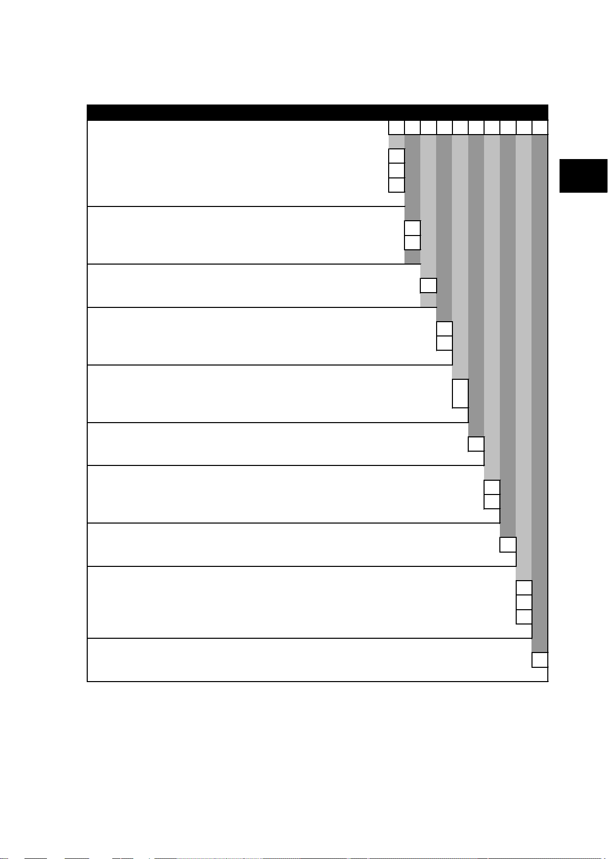
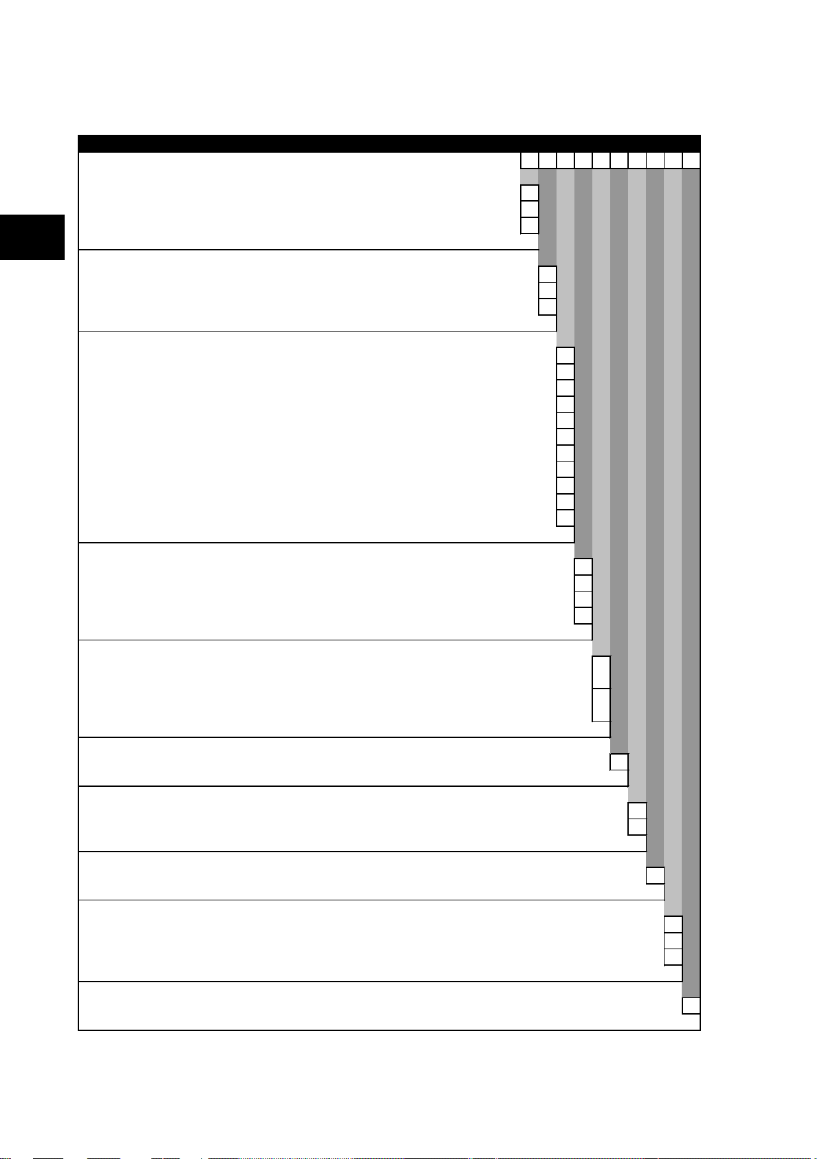
The measurement information and relay settings that can be accessed from the four
interfaces are summarized in Table 1.
Page 44

P74x/EN GS/Na7
Getting Started
(GS) 3
MiCOM P741, P742, P743
GS
dat a
settings
Column header
Contr ol&suppor t
Group 1
Group 4
Up to4protectionsettinggroups
System dat a
V
iew records
DIFF
BUSBARPROT
BUSBAR
OPTION
P0106ENb
INP UTS
LABELS
OUTPUT
LABELS
DIFF
BUSBARPROT
BUSBAR
OPTION
INP UTS
LABELS
OUTPUT
LABELS
-12
Keypad/
LCD
Display & modification of
all settings
Digital I/O signal status
Display/extraction of
measurements
Display/extraction of fault
records
Extraction of disturbance
records
Programmable scheme
logic settings
Reset of fault & alarm
records
Clear event & fault
records
Time synchronization
Control commands
Courier
• •
IEC870-5-
103
IEC
61850
• • • •
• • • •
• •
• • •
•
• • •
• •
• • •
• • •
•
Table 1
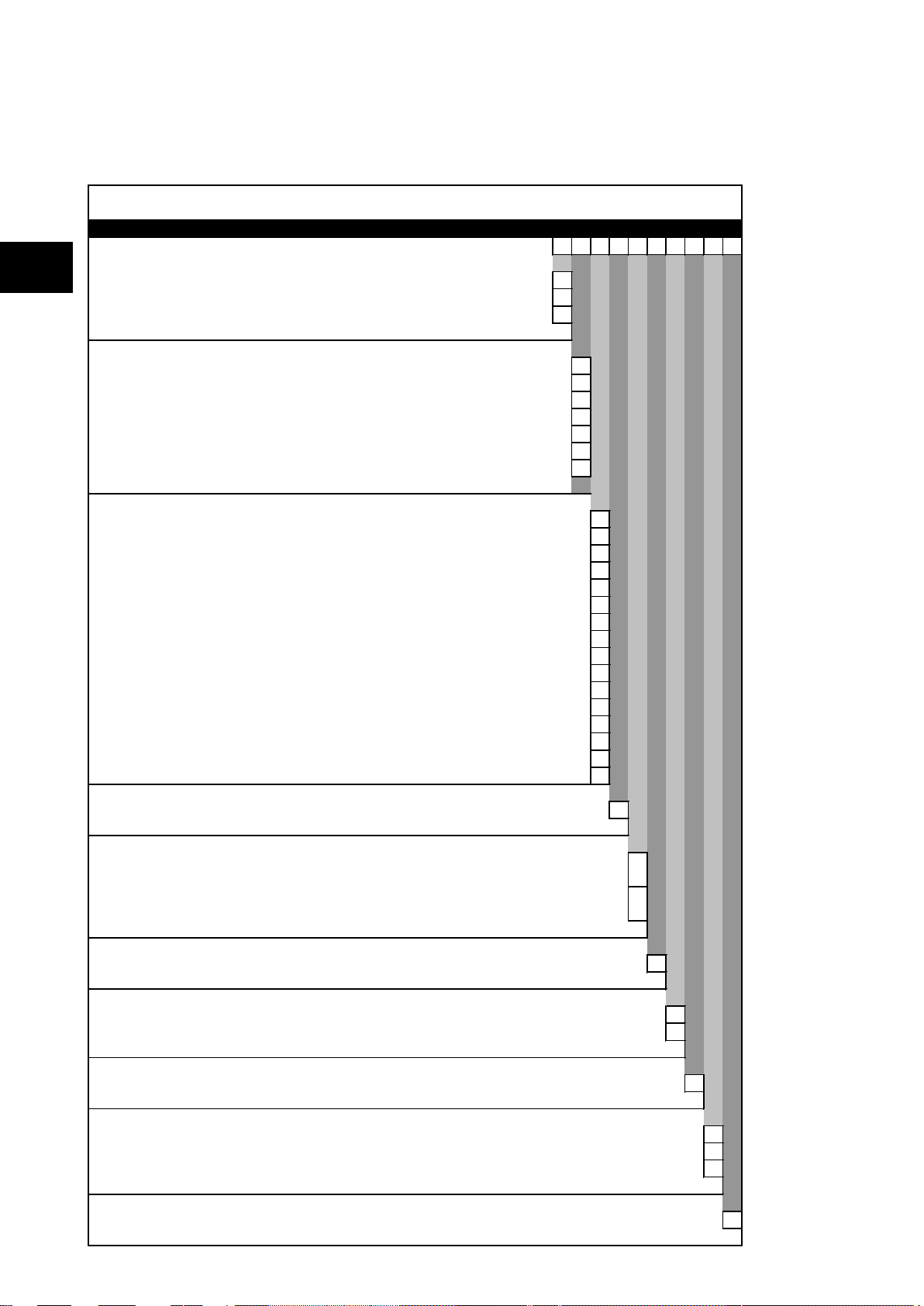
1.5 Menu structure
The relay’s menu is arran ged in a tabular structur e. Each setting in the menu is referred to
as a cell, and each cell in t he menu may be accessed by reference to a row and column
address. The settings are arranged so that each column contains related settings, for
example all of the disturbance recorder set tings are contained with in the same column. As
shown in Figure 6, the top row of each column contains the heading that describes the
settings contained with in that c olumn. Mov em ent bet ween the c olumns of the m enu can onl y
be made at the c olum n hea ding level. F or a complete list of all of t he m enu se ttin gs, s ee th e
Settings chapter P74x/EN ST.
FIGURE 6: MENU STRUCTURE
Page 45

Getting Started
P74x/EN GS/Na7
MiCOM P741, P742, P743
13
GS
Read access to all settings, alarms, event
All of the settings in the menu fall into one of three categories; protection settings,
disturbance recorder settings, or control and support (C&S) settings. One of two different
methods is used to change a setting depending on which category the setting falls into.
Control and support settings are stored and used by the relay immediately after they are
entered. For either protection setti ngs or disturbance r ecorder settings, the relay stores the
new setting values in a temporar y ‘scratchp ad’. It activ ates all t he new s ettings together , but
only after it has been co nfirmed that the new settings are to be adopted. This techniq ue is
employed to provide extr a sec urit y, and so that s ever al sett ing ch anges that ar e m ade within
a group of protection settings will all take effect at the same time.
1.5.1 Protection settings The protection settings include the following items:
− Protection element settings
− Scheme logic settings
There are four groups of protection settings, with each group containing the same setting
cells. One group of pr otection settings is selected as the active group, and is used b y the
protection elements.
(GS) 3-
1.5.2 Disturbance recorder settings The disturbance recor der settings inclu de the record durati on and trigger posit ion, selection
of analogue and digital signals to record, and the signal sources that trigger the recording.
1.5.3 Control and support settings The control and support settings include:
− Relay configuration settings
− Open/close circuit breaker
− CT & VT ratio settings
− Reset LEDs
− Active protection setting group
− Password & language settings
− Communications settings
− Measurement settings
− Event & fault record settings
− User interface settings
− Commissioning settings
1.6 Password protection
The menu structure contains three levels of access. The level of access that is enabled
determines which of the re lay’s settings can be changed and is contro lled by entry of two
different passwords. The levels of access are summarized in Table 2.
Access level Operations enabled
Level 0
No password required
records and fault records
Page 46

P74x/EN GS/Na7
Getting Started
(GS) 3
MiCOM P741, P742, P743
GS
-14
Access level Operations enabled
As level 0 plus:
Control commands, e.g.
Level 1
Password 1 or 2 required
Circuit breaker open/close (when available).
Reset of fault and alarm conditions.
Reset LEDs.
Clearing of event and fault records.
Level 2
Password 2 required
Table 2
Each of the two passwords is 4 characters of upper case text. The factor y default for both
passwords is AAAA. Each passwor d is user-changea ble once it has been correc tly entered.
Entry of the password is achie ved ei ther b y a prom pt when a setti ng ch ange is at tem pted, or
by moving to the ‘Password’ cell in the ‘System data’ column of the menu. The level of
access is independently enabled for each interf ace, th at is to s ay if level 2 ac cess is enab led
for the rear communication port, the front panel access will remain at level 0 unless the
relevant password is enter ed at the front panel. The access level enabled by th e password
entry will tim e-out i ndependently for each interfac e after a period of inactivit y and revert to
the default level. If the pas s wor ds are los t a n emergency password can b e s upp li ed - contact
GE with the relay’s seria l number. The current leve l of access enabled for an interface can
be determined by exam ining the 'Access level' cell in the 'S ystem data' column, the access
level for the front pan el User Interface (U I), can also be foun d as one of the def ault display
options.
The relay is suppli ed with a default acc ess level of 2, such th at no password is r equired to
change any of the relay settings. It is also possible to set the default m enu access level to
either level 0 or level 1, preventing write access to the relay settings without the correct
password. The default m enu access level is s et in the ‘Password con trol’ cell whic h is found
in the ‘System data ’ column of the menu ( note that this setting can on ly be changed when
level 2 access is enabled).
As level 1 plus:
All other settings
1.7 Relay configuration
The relay is a multi-function device that supp orts numerous diff erent protection, control and
communication featur es. To sim plify the setting of the rela y, there is a co nfiguration sett ings
column which can be used to enable or disable many of the functions of the relay. The
settings associated with any function that is disabled are made invisible, i.e. they are not
shown in the menu. To disable a function change the relevant cell in the ‘Configuration’
column from ‘Enabled’ to ‘Disabled’.
The configuration colum n controls which of the four protection settings groups is s elected as
active through the ‘Acti ve s ett ings ’ c ell. A pr otection setting group can a lso be disabled in the
configuration colum n, pr ovided it is not the pr ese nt activ e gro up. Sim ilarl y, a d isable d sett ing
group cannot be set as the active group.
1.8 Front panel user interface (keypad and LCD)
When the keypad is exp os ed it pr o vides f ull acc es s to the menu options of the re l a y, with the
information displayed on the LCD.
, , and k eys which are used f or menu navig ation and sett ing value changes
The
include an auto-repeat function that comes into operation if any of these keys are held
continually pressed. This can be used to speed up b oth setting value changes and menu
navigation; the longer the key is he ld depress ed, the fas ter the rate of change or m ovement
becomes.
Page 47

Getting Started
P74x/EN GS/Na7
MiCOM P741, P742, P743
15
GS
(GS) 3-
FIGURE 7: FRONT PANEL USER INTERFACE
1.8.1 Default display and menu time-out The front panel m enu has a default display, the c ontents of which can be se lected from the
following options in the ‘default display’ cell of the ‘Measure’t. setup’ column:
− Date and time
− Relay description (user defined)
− Plant reference (user defined)
− Check zone bias currents (A, B, C)
− Check zone differential currents (A, B, C)
From the default disp lay it is als o pos sible to vie w the other defau lt disp la y option s using the
and keys. However, if there is no keypad activity for the 15 minute timeout period, the
default display will revert to that select ed by the setting an d the LCD b ack light will tur n off . If
this happens any setting c hanges that have not been confirmed will be lost and the original
setting values maintained.
Whenever there is an uncleared alarm present in the relay (e.g. fault record, protection
alarm, control alarm etc.) the default display will be replaced by:
Alarms/Faults
Present
Entry to the menu str uctur e of the r elay is made from the default display and is not affected if
the display is showing the ‘Alarms/Faults present’ message.
Page 48

P74x/EN GS/Na7
Getting Started
(GS) 3
MiCOM P741, P742, P743
GS
-16
1.8.2 Menu navigation and setting browsing The menu can be bro ws ed us ing the four arrow ke ys, foll o wing t he s tr ucture shown in Figure
7. Thus, starting at the d efault display the
select the required c olumn heading use th e
the column can then be viewed by using the
column header either b y holding the [up arrow symbo l] key down or b y a single press of t he
clear key
return to the defaul t display, press the
headings. It is not poss ible to go s tra ight to the d efault disp la y from within o ne of the co lum n
cells using the auto-rep eat facility of the
heading. To move to the default display, the
1.8.3 Hotkey menu navigation The hotkey menu can be browsed using the two keys directl y below the LCD. T hese are
known as direct ac cess keys. The direct access k eys perform the func tion that is disp layed
directly above them on the LCD. Thus, to access t he hotkey menu from the default display
the direct access k ey below the “HOT KEY” text mus t be pressed. Once in the hotke y menu
the ⇐ and ⇒ k e ys ca n b e us ed t o s c rol l b et ween the available optio ns an d t he di r ect ac c es s
keys can be used to contro l the function curre ntly displa yed. If neither the ⇐ or ⇒ k eys are
pressed with 20 sec onds of entering a hotkey sub menu, the relay will revert t o the default
display. The clear k ey
hotkey menu. The layout of a typical page of the hotkey menu is described below:
. It is on ly possible to move across columns at the column he ading level. To
will also act to re turn to the default menu from any page of the
key will disp lay the first column head ing. To
and k eys. The setting data conta ined in
and keys. It is pos sible to retur n to the
key or the clear k ey from any of the column
key, as the auto-rep eat will stop at the column
key must be released and pressed again.
• The top line shows the contents of the previous and next cells for easy menu navigation
• The centre line shows the function
• The bottom line shows the options assigned to the direct access keys
The functions available in the hotkey menu are listed below:
1.8.3.1 Setting group selection The user can either scroll using <<NXT GRP>> through the available setting groups or
<<SELECT>> the setting group that is currently displayed.
When the SELECT button is pressed a screen confirming the current setting group is
displayed for 2 seconds before the user is prompted with the <<NXT GRP>> or
<<SELECT>> options again. The user can exit the sub menu by using the left and right
arrow keys.
For more information on setting group selec tion refer to “Changing s etting group” sec tion in
the Operation section (P74x/EN OP).
1.8.3.2 Control inputs – user assignable functions The number of control inputs (user assignable functions – USR ASS) represented in the
hotkey menu is user conf igurabl e in t he “CT RL I/ P CON FIG” c olum n. T he chosen inputs can
be SET/RESET using the hotkey menu.
For more inform ation refer to the “Contro l Inputs” s ection in th e Operation section ( P74x/EN
OP).
Page 49

Getting Started
P74x/EN GS/Na7
MiCOM P741, P742, P743
17
GS
HOT KEY MENU
EXIT
Description
MiCOM P741
HOTKEY
<USER 32
STG GP>
SETTING GROUP 1
SELECT
<MENU
USER 01>
NXT GRP
CONTROL INPUT 1
ON
<STG GP
USER 02>
EXIT
CONTROL INPUT 32
ON
<USER 31
MENU>
EXIT
SETTING GROUP 2
SELECT
<MENU
USER 01>
NXT GRP
SETTING GROUP 2
SELECTED
<MENU
USER 01>
CONTROL INPUT 1
ON
<MENU
USER 02>
CONTROL INPUT 1
EXIT
<MENU
USER 02>
OFF
Confirmation
screen
displayedfor
2 seconds
Confirmation
screen
displayedfor
2 seconds
Default Display
NO TE: <<EXIT>> K ey returns
the userto the Hotkey
MenuScreen
P3915ENa
1.8.3.3 Hotkey menu navigation
(GS) 3-
1.8.4 Password entry When entry of a password is required the following prompt will appear:
A flashing cursor will indica te which char acter field of the pas sword m ay be chan ged. Press
the
character fields of the password, use the
pressing the enter key
password is entered. At this point a message will be displayed indicating w hether a correct
password has been entere d and if so what l evel of acc ess has been unl ocked. If this level is
sufficient to edit the selected se tting then the d isplay will return t o the setting page to allow
the edit to continue. If the c orrect level of passwor d has not been e ntere d then th e pass word
prompt page will be returned to. To escape from this prompt press the clear key
Alternatively, the password can be entered using the ‘Password’ cell of the ‘System data’
column.
For the front panel user interface the password protected access will revert to the default
access level after a keypad inactivity tim e-out of 15 minutes. It is poss ible to m anually reset
the password protection to the default level by moving to the ‘Password’ menu cell in the
‘System data’ column and pressing the clear key
FIGURE 8: HOTKEY MENU NAVIGATION
Enter password
**** Level 1
Note: The password required to edit the setting is the prompt as shown
above.
and keys to vary each character between A and Z. To move between the
and keys. The password is confirmed by
. The display will revert to ‘Enter Password’ if an incorrect
.
instead of entering a password.
1.8.5 Reading and clearing of alarm messages and fault records
Page 50

P74x/EN GS/Na7
Getting Started
(GS) 3
MiCOM P741, P742, P743
GS
-18
The presence of one or m ore alarm messages will be indic ated b y the def ault disp la y and by
the yellow alarm LED f lashing. The alarm messages can either be self-resetting or latc hed,
in which case the y must be cleared manua lly. To view the alar m messages press the r ead
key . W hen all alarm s have bee n vie wed, but not c l eared, t he alarm LED wil l change f rom
flashing to constant illum ination and the lat est fault recor d will be displayed (if there is one).
To scroll through th e pages of this use the k ey. When all p ages of the fault record have
been viewed, the following prompt will appear:
Press clear to
reset alarms
To clear all alarm messages press ; to return to the alarms/faults present display and
leave the alarm s uncleared, pres s . Depend ing on the pass word configuratio n settings, it
may be necessary to enter a password before the alarm messages can be cleared (see
section on password entr y). When the alarms have been c leared the yellow alarm LED will
extinguish, as will the red trip LED if it was illuminated following a trip.
Alternatively it is possible to accelerate the procedure, once the alarm viewer has been
entered using the key, the key can be pressed , and this will move t he disp lay straight
to the fault record. Pressing again will move straight to the alarm reset prom pt where
pressing once more will clear all alarms.
Note: When viewing the fault inform ation for P741 by pressing the r ead key,
1.8.6 Setting changes To change the value of a setting, first navigate the menu to display the relevant cell. To
change the cell value pr ess the enter key , which will bring up a flashing cursor on the
LCD to indicate that the value can be changed. This will only happen if the appropriate
password has been entered, otherwise the prompt to enter a password will appear. The
setting value can then be changed by pressing the or keys. If the setting to be
changed is a binar y value or a text str ing, the required bit or character to be c hanged must
first be selected using the and ke ys. When t he desir ed new value h as been r eached it is
confirmed as the new setting value by pressing . Alternatively, the new value will be
discarded either if the clear button is pressed or if the menu time-out occurs.
For protection group settings and disturbance recorder settings, the changes must be
confirmed before they are used by the relay. To do this, when all required changes have
been entered, return to the colum n heading level and press the key. Prior to returning to
the default display the following prompt will be given:
Pressing will r esult in the new settings be ing ado pt ed, pr ess in g will cause the rel a y to
discard the newly entered values. It should be noted that, the setting values will also be
discarded if the menu time out occurs before the setting changes have been confirmed.
Control and support settings will b e updated imm ediately after the y are entered, with out the
‘Update settings?’ prompt.
only information for PU’s 7 to 22 is available.
Update settings?
Enter or clear
1.9 Front communication port user interface
The front comm unication port is prov ided by a 9-pin female D-type con nector located under
the bottom hinged cover. It pr ovides EIA(R S)232 ser ial data com munication a nd is intend ed
for use with a PC loc ally to the relay (up to 15m distance) as shown in Figure 9. This port
supports the Courier c ommunication protocol only. Couri er is the comm unication language
developed by GE to allow com m unication with its ran ge of protectio n rela ys. The fr ont port is
particularly designed for use with the relay settings program S1 that is a Windows 98,
Windows NT4.0, Windows 2000 or Windows XP based software package.
Page 51

Getting Started
P74x/EN GS/Na7
MiCOM P741, P742, P743
19
GS
d
FIGURE 9: FRONT PORT CONNECTION
(GS) 3-
The relay is a Data Com munication Equipment (DCE ) device. Thus the pin connec tions of
the relay’s 9-pin front port are as follows:
Pin no. 2 Tx Transmit data
Pin no. 3 Rx Receive data
Pin no. 5 0V Zero volts common
None of the other pins are connected in the relay. The relay should be connected to the
serial port of a PC, usually called COM1 or COM2. PCs are normally Data Terminal
Equipment (DTE) devices whic h h av e a ser ia l p ort pin connection as below ( if in doub t check
your PC manual):
25 Way 9 Way
Pin no. 2 3 2 Rx Receive data
Pin no. 3 2 3 Tx Transmit data
Pin no. 5 7 5 0V Zero volts common
For successful data com municat ion, t he T x pin on t he rela y m ust be connec ted t o the Rx p in
on the PC, and the Rx pin on the re la y mus t be c onne c ted to the T x pin on the P C, as s hown
in Figure 10. Therefore, providing th at th e PC is a DT E with pin co nnec tions as given above ,
a ‘straight through’ s erial c onnector is r equired, i.e. on e that con nects p in 2 to p in 2, pin 3 to
pin 3, and pin 5 to pin 5. Note that a common cause of difficulty with serial data
communication is connecting Tx to Tx and Rx to Rx. This could happen if a ‘cross-over’
serial connector is us ed, i.e. one t hat connect s pin 2 to pin 3, and pi n 3 to pin 2, or if the PC
has the same pin configuration as the relay.
Page 52

P74x/EN GS/Na7
Getting Started
(GS) 3
MiCOM P741, P742, P743
GS
-20
Having made the physical connection from the relay to the PC, the PC’s communication
settings must be conf igured to m atch those of the r elay. The re lay’s comm unication setti ngs
for the front port are fixed as shown in the table below:
Protocol Courier
Baud rate 19,200 bits/s
Courier address 1
Message format 11 bit - 1 start bit, 8 data bits, 1 parity bit (even parity), 1 stop bit
The inactivity tim er f or the fr ont port is s et at 15 minutes. This contr ols ho w long t h e relay will
maintain its level of pas sword access on th e front port. If no m essages are received on the
front port for 15 minutes then any password access level that has been enabled will be
revoked.
1.9.1 Front courier port The front EIA(RS)232
communication. It is designed for use during installation and commissioning/maintenance
and is not suitable for perm anent connection . Since this interface will not be us ed to link the
relay to a substation communication system, some of the features of Courier are not
implemented. These are as follows:
FIGURE 10: PC – RELAY SIGNAL CONNECTION
1
9 pin port supports the Courier protocol for one to one
Automatic Extraction of Event Records:
− Courier Status byte does not support the Event flag
− Send Event/Accept Event commands are not implemented
Automatic Extraction of Disturbance Records:
− Courier Status byte does not support the Disturbance flag
Busy Response Layer:
− Courier Status byte does not support t he B us y fl ag, th e o nly response to a r equ e s t will
be the final data
Fixed Address:
− The address of the front courier port is always 1, the Change Device address
command is not supported.
Fixed Baud Rate:
− 19200 bps
It should be noted t hat alt hough autom atic extrac tion of even t and disturb ance re cor ds is not
supported it is possible to manually access this data via the front port.
1.10 S1 Agile relay communications basics
1
This port is actually compliant to EIA(RS)574; the 9-pin version of EIA(RS)232, see www.tiaonline.org.
The EIA(RS)232 front communication port is intended for use with the relay settings program
S1 Agile. This program runs on WindowsTM 2000, XP, Vista or Windows 7 and is the
universal IED Support Software used for direct access to all stored data in any IED.
S1 provides full access to:
− Px40, Modulex series, K series, L series relays
− Mx20 measurement units
Connecting to the P74x relay using S1 Agile
Page 53

Getting Started
P74x/EN GS/Na7
MiCOM P741, P742, P743
21
GS
This section is intended as a quick start guide to using S1 Agile and assumes you have a
copy installed on your PC. See the S1 Agile program online help or ‘MiCOM P40 Agile
Modular and Compact Ranges, Settings Application Software User Guide’, P40-M&CR-UG
for more information.
1. Make sure the EIA(RS)232 serial cable is properly connected between the port on the
front panel of the relay and the PC.
2. Start S1 Agile and click the Quick Connect tab and select Create a New System.
3. Check the Path to System file is correct, then enter the name of the system in the
Name field. If you need to add a brief description of the system, use the Comment
field.
4. Click OK.
5. Select the device type.
6. Select the communications port.
7. Once connected, select the language for the settings file, the device name, then click Finish.
The configuration is updated.
(GS) 3-
8. In the Agile Explorer window, select Device > Supervise Device… to control the relay
directly.
1.10.1 Off-line use of S1 Agile S1 Agile can also be used as an off-line tool to prepare settings, without access to the relay.
1. If creating a new system, in the Agile Explorer, select create new system. Then
right-click the new system and select New substation.
2. Right-click the new substation and select New voltage level.
3. Then right-click the new voltage level and select New bay.
4. Then right-click the new bay and select New device.
You can add a device at any level, whether it is a system, substation, voltage or bay.
5. Select a device type from the list, then enter the relay type, such as P645. Click Next.
6. Enter the full model number and click Next.
7. Select the Language and Model, then click Next.
8. Enter a unique device name, then click Finish.
9. Right-click the Settings folder and select New File. A default file 000 is added.
10. Right-click file 000 and select click Open. You can then edit the settings. See the S1 Agile
program online help for more information.
Page 54

P74x/EN GS/Na7
Getting Started
(GS) 3
MiCOM P741, P742, P743
GS
-22
2. CONFIGURING THE ETHERNET INTERFACE
The way in which you configure the Ethernet interface depends on the particular type of
interface you have. If you have a DNP3.0 interface, use the DNP setting file to configure the
Ethernet interface. Otherwise you should use the IED configurator tool in MiCOM S1 Agile.
Note: Further information is available in the Communications chapter
2.1 Configuring the Ethernet Interface for IEC 61850
1. Open MiCOM S1 Agile:
2. Select Tools > IEC61850 IED Configurator
3. Select Device > Manage IED
4. Select Px40
5. Enter the address of the IED you want to manage (this will always be '1' if you are
connected via the front port)
6. Click Next. The following screen appears
7. Select Extract Configuration, Active Bank
Page 55

Getting Started
P74x/EN GS/Na7
MiCOM P741, P742, P743
23
GS
8. Select the model. The IP address data is then revealed:
9. To change the address values, select View > Enter Manual Editing Mode
(GS) 3-
10. Enter the required IP configuration and select the green download button:
Page 56

P74x/EN GS/Na7
Getting Started
(GS) 3
MiCOM P741, P742, P743
GS
IED (IP1)
IED Configurator
XXX.YYY.254.ZZZ
Fixed
SW2
Switch Manager (SHP or DHP)
RSTP Configurator (RSTP)
REB (IP2)
P4442ENa
-24
3. CONFIGURING THE REDUNDANT ETHERNET BO ARD
An IP address is a logical address assigned to devices in a computer network that uses the
Internet Protocol (IP) for communication between nodes. IP addresses are stored as binary
numbers but they are represented using Decimal Dot Notation, whereby four sets of decimal
numbers are delimited by dots as follows:
XXX.XXX.XXX.XXX
For example: 10.86.254.85
An IP address within a network is usually associated with a subnet mask that defines which
network the device resides. A subnet mask takes the same form of an IP address.
For example: 255.255.255.0
A full explanation of IP addressing and subnet masking is beyond the scope of this guide.
Further information is available on application.
Both the IED and the REB (Redundant Ethernet Board) each have their own IP address.
FIGURE 11 shows the IED as IP1 and the REB as IP2.
Note: IP1 and IP2 are different but use the same subnet mask.
The switch IP address must be configured through the network.
FIGURE 11: IED AND REB IP ADDRESS CONFIGURATION
3.1 Configuring the IED IP Address
The IP address of the IED is configured using the IED Configurator software in S1 Agile.
For IEC 61850, the IED IP address is set using the IED Configurator.
There are 254 addresses available, which are configurable in the last octet. These are
within the range 01 to 254 decimal, which is equivalent 01 to FE hexadecimal, or 00000001
to 11111110 binary.
As with all IP networks, the first and last addresses (00 and FF) should not be used as these
are reserved for the network address and broadcast address respectively.
Note: In the IED Configurator, ensure that the port type is set to "Copper" (even if
3.2 Configuring the Board IP Address
The IP address of the REB is configured in both software and hardware, as shown in
FIGURE 11. Therefore, this must be configured before connecting the IED to the network to
avoid an IP address conflict.
Configuring the First Two Octets of the Board IP Address
If using SHP or DHP, the first two octets are configured using Switch Manager or an SNMP
MIB browser. An H35 (SHP) or H36 (DHP) network device is needed in the network to
configure the Px40 redundant Ethernet board IP address using SNMP.
If using Rapid Spanning Tree Protocol (RSTP), the first two octets are configured using the
RSTP Configurator software tool or using an SNMP MIB browser.
redundant fibres are being used)
Page 57

Getting Started
P74x/EN GS/Na7
MiCOM P741, P742, P743
25
GS
P4389ENb
1
2
4
8
16
32
64
Unused
SW2 Top view
ON
Example address
decimal 85
1 + 4 + 16 + 64 = 85
(GS) 3-
Configuring the Third Octet of the Board IP Address
The third octet is fixed at 254 (FE hex, 11111110 binary regardless of the protocol.
Configuring the Last Octet of the Board IP Address
The last octet is configured using the 8-way board address DIP switch SW2 on the REB.
3.3 RSTP Configuration
FIGURE 12: REB ADDRESS SWITCHES (SW2)
Details of how to access the switches on the REB are provided in the Installation chapter.
Caution: This hardware configuration should ideally take place before the unit is
installed. If this is not possible, this must be carried out by authorized
installation engi neers.
If you are using RSTP, you will need the RSTP configurator software. This is available from
GE on request.
The RSTP Configurator software is used to identify a device, configure the IP address,
configure the SNTP IP address and configure RSTP settings.
Installing RSTP Configurator
1. Double click WinPcap_4_0.exe to install WinPcap.
2. Double click ALSTOM Grid-RSTP Configurator.msi to install the RSTP Configurator.
3. The setup wizard appears. Click Next and follow the on-screen instructions to run the
installation.
Starting the RSTP Configurator
1. To start the RSTP Configurator, select Programs > RSTP Configurator > RSTP
Configurator.
Page 58

P74x/EN GS/Na7
Getting Started
(GS) 3
MiCOM P741, P742, P743
GS
-26
2. The Login screen appears. For user mode login, enter the Login name as User and
click OK with no password.
3. If the login screen does not appear, check all network connections.
4. The main window of the RSTP Configurator appears. The Network Board drop-down
list shows the Network Board, IP Address and MAC Address of the PC in which the
RSTP Configurator is running.
Device Identification
1. To configure the REB, go to the main window and click Identify Device.
2. The REB connected to the PC is identified and its details are listed as shown below:
• Device address
• MAC address
• Version number of the firmware
• SNTP IP address
• Date & time of the real-time clock, from the board.
Note: Due to the time needed to establish the RSTP protocol, it is necessary to
wait 25 seconds between connecting the PC to the IED and clicking the
Identify Device button.
IP Address Configuration
1. To change the network address component of the IP address, go to the main window
and click the IP Config button. The Device setup screen appears. The first three
octets of the board IP address can be configured.
Note: The last octet is set using the DIP switches (SW2) next to the ribbon
connector.
2. Enter the required board IP address and click OK. The board network address is
updated and displayed in the main window.
SNTP IP Address Configuration
1. To Configure SNTP server IP address, go to the main window and click the SNTP
Config button. The Device setup screen appears.
Page 59

Getting Started
P74x/EN GS/Na7
MiCOM P741, P742, P743
27
GS
2. Enter the required SNTP MAC and server IP address, then click OK. The updated
SNTP server IP address appears in the main screen.
Equipment
1. To view the MAC addresses learned by the switch, go to the main window and click
the Identify Device button. The selected device MAC address then appears
highlighted.
2. Click the Equipment button. The list of MAC addresses learned by the switch and the
corresponding port number are displayed.
(GS) 3-
RSTP Parameters
1. To view or configure the RSTP Bridge Parameters, go to the main window and click
the device address to select the device. The selected device MAC address appears
highlighted.
2. Click the RSTP Config button. The RSTP Config screen appears.
Page 60

P74x/EN GS/Na7
Getting Started
(GS) 3
MiCOM P741, P742, P743
GS
-28
1. To view the available parameters in the board that is connected, click the Get RSTP
Parameters button.
2. To set the configurable parameters such as Bridge Max Age, Bridge Hello Time,
Bridge Forward Delay, and Bridge Priority, modify the parameter values and click
Set RSTP Parameters as below:
S.No Parameter
1 Bridge Max Age 20 6 40
2 Bridge Hello Time 2 1 10
3 Bridge Forward Delay 15 4 30
4 Bridge Priority 32768 0 61440
Default Value
(seconds)
Minimum Value
(seconds)
Maximum Value
(seconds)
Bridge Parameters
1. To read the RSTP bridge parameters from the board, go to the main window and click
the device address to select the device. The RSTP Config window appears and the
default tab is Bridge Parameters.
2. Click the Get RSTP Parameters button. This displays all the RSTP bridge
parameters from the Ethernet board.
1. To modify the RSTP parameters, enter the values and click Set RSTP Parameters.
2. To restore the default values, click Restore Default and click Set RSTP Parameters.
3. The grayed parameters are read-only and cannot be modified.
Port Parameters
This function is useful if you need to view the parameters of each port.
1. From the main window, click the device address to select the device and the RSTP
Config window appears.
2. Select the Port Parameters tab, then click Get Parameters to read the port
parameters.
3. Alternatively, select the port numbers to read the parameters.
Page 61

Getting Started
P74x/EN GS/Na7
MiCOM P741, P742, P743
29
GS
(GS) 3-
Port States
This is used to see which ports of the board are enabled or disabled.
1. From the main window, click the device address to select the device. The RSTP
Config window appears.
2. Select the Port States tab then click the Get Port States button. This lists the ports
of the Ethernet board. A tick shows they are enabled.
Page 62

P74x/EN GS/Na7
Getting Started
(GS) 3
MiCOM P741, P742, P743
GS
-30
4. CONFIGURING THE DATA PROTOCOLS
Depending on the model, various protocols can be used with the serial rear ports. However,
only one protocol can be configured at any one time on any one IED. The range of available
communication settings depend on which protocol has been chosen
4.1 Courier Configuration
To use the rear port with Courier, you can configure the settings using the HMI panel.
Courier can be used with either a copper connection or a fibre connection.
1. Select the CONFIGURATION column and check that the Comms settings cell is set
to Visible.
2. Select the COMMUNICATIONS column.
3. Move to the first cell down (RP1 protocol). This is a non settable cell, which shows
the chosen communication protocol – in this case Courier.
COMMUNICATIONS
RP1 Protocol
Courier
4. Move down to the next cell (RP1 Address). This cell controls the address of the IED.
Up to 32 IEDs can be connected to one spur. It is therefore necessary for each IED to
have a unique address so that messages from the master control station are accepted
by one IED only. Courier uses an integer number between 0 and 254 for the IED
address. It is important that no two IEDs have the same address.
COMMUNICATIONS
RP1 Address
255
5. Move down to the next cell (RP1 InactivTimer). This cell controls the inactivity timer.
The inactivity timer controls how long the IED waits without receiving any messages
on the rear port before it reverts to its default state, including revoking any password
access that was enabled. For the rear port this can be set between 1 and 30 minutes.
COMMUNICATIONS
RP1 Inactivtimer
10.00 mins.
6. If the optional fibre optic connectors are fitted, the RP1 PhysicalLink cell is visible.
This cell controls the physical media used for the communication (Copper or Fibre
optic).
7. Move down to the next cell (RP1 Card Status). This cell is not settable. It just
displays the status of the chosen physical layer protocol for RP1.
COMMUNICATIONS
RP1 Physical Link
Copper
COMMUNICATIONS
RP1 Card Status
K-Bus OK
Page 63

Getting Started
P74x/EN GS/Na7
MiCOM P741, P742, P743
31
GS
8. Move down to the next cell (RP1 Port Config). This cell controls the type of serial
connection. Select between K-Bus or RS485.
COMMUNICATIONS
RP1 Port Config
K-Bus
9. If using EIA(RS)485, the next cell selects the communication mode. The choice is
either IEC 60870 FT1.2 for normal operation with 11-bit modems, or 10-bit no parity.
If using K-Bus this cell will not appear.
COMMUNICATIONS
RP1 Comms Mode
IEC 60870 FT1.2
10. If using EIA(RS)485, the next cell down controls the baud rate. Three baud rates are
supported; 9600, 19200 and 38400. If using K-Bus this cell will not appear as the
baud rate is fixed at 64kbps.
(GS) 3-
COMMUNICATIONS
RP1 Baud Rate
Note: If you modify protection and disturbance recorder settings using an on-line
editor such as PAS&T, you must confirm them. To do this, from the
Configuration column select the Save changes cell. Off-line editors such as
MiCOM S1 Agile do not need this action for the setting changes to take
effect.
4.2 IEC 61850 Configuration
The only IEC 61850 configuration changes you can make with the HMI panel is to turn
GOOSE on or off.
4.3 IEC 61850 Configuration
You cannot configure the device for IEC 61850 using the HMI panel on the product. For this
you must use the IED Configurator.
IEC 61850 allows IEDs to be directly configured from a configuration file. The IED’s system
configuration capabilities are determined from an IED Capability Description file (ICD),
supplied with the product. By using ICD files from the products to be installed, you can
design, configure and even test (using simulation tools), a substation’s entire protection
scheme before the products are even installed into the substation.
19200
To help with this process, MiCOM S1 Agile provides an IED Configurator tool, which allows
the pre-configured IEC 61850 configuration file to be imported and transferred to the IED.
As well as this, you can manually create configuration files for MiCOM IEDs, based on their
original IED capability description (ICD file).
Other features include:
− The extraction of configuration data for viewing and editing.
− A sophisticated error checking sequence to validate the configuration data before
sending to the IED.
Note: To help the user, some configuration data is available in the IED
CONFIGURATOR column, allowing read-only access to basic configuration
data.
Note: The IEC 61850 option is only available on the P741 and the P743.
Page 64

P74x/EN GS/Na7
Getting Started
(GS) 3
MiCOM P741, P742, P743
GS
-32
4.3.1 IEC 61850 Configuration Banks To help version management and minimize down-time during system upgrades and
maintenance, the MiCOM IEDs have incorporated a mechanism consisting of multiple
configuration banks. These configuration banks fall into two categories:
− Active Configuration Bank
− Inactive Configurati on Bank
Any new configuration sent to the IED is automatically stored in the inactive configuration
bank, therefore not immediately affecting the current configuration.
When the upgrade or maintenance stage is complete, the IED Configurator tool can be used
to transmit a command, which authorizes activation of the new configuration contained in the
inactive configuration bank. This is done by switching the active and inactive configuration
banks. The capability of switching the configuration banks is also available using the IED
CONFIGURATOR column of the HMI.
The SCL Name and Revision attributes of both configuration banks are also available in the
IED CONFIGURATOR column of the HMI.
4.3.2 IEC 61850 Network Connectivity Configuration of the IP parameters and SNTP time synchronization parameters is performed
by the IED Configurator tool. If these parameters are not available using an SCL file, they
must be configured manually.
As the IP addressing will be completely detached and independent from any public network,
it is up to the company’s system administrator to establish the IP addressing strategy. Every
IP address on the network must be unique. This applies to all devices on the network.
Duplicate IP addresses will result in conflict and must be avoided. The IED will check for a
conflict on every IP configuration change and at power up. An alarm will be raised if an IP
conflict is detected.
The IED can be configured to accept data from other networks using the Gateway setting. If
multiple networks are used, the IP addresses must be unique across networks.
Page 65

Getting Started
P74x/EN GS/Na7
MiCOM P741, P742, P743
33
GS
IED
Ethernet switch
TXA
Media
Converter
RJ45
V01806
RXA
TXB RXB
RXA
TXA
RXB TXB
TX
RX
(a) (b)
IED
RXA
TXA
RXB TXB
5. PRP/HSR CONFIGURATOR
The PRP/HSR Configurator tool is intended for MiCOM Px4x IEDs with redundant Ethernet
using PRP (Parallel Redundancy Protocol), or HSR (High-ava ilability Seamless
Redundancy). This tool is used to identify IEDs, switch between PRP and HSR or configure
their parameters, configure the redundancy IP address, or configure the SNTP IP address.
5.1 Connecting the IED to a PC
Connect the IED to the PC on which the Configurator tool is used. This connection is done
through an Ethernet switch or through a media converter.
(GS) 3-
FIGURE 13: CONNECTION USING (A) AN ETHERNET SWITCH AND (B) A MEDIA
5.2 Installing the Configurator
To install the configurator:
1. Double click the WinPcap installer.
2. Double click the Configurator installer.
5.3 Starting the Configurator
3. Click Next and follow the on-screen instructions.
To start the configurator:
1. Select the Configurator from the Windows Programs menu.
2. The Login screen appears. For user mode login, enter the Login name as User and
click OK with no password.
3. If the login screen does not appear, check all network connections.
4. The main window appears. In the bottom right-hand corner of the main window, click
the Language button to select the language.
COVER
Page 66

P74x/EN GS/Na7
Getting Started
(GS) 3
MiCOM P741, P742, P743
GS
-34
5. The Network Board drop-down list shows the Network Board, IP Address and MAC
Address of the
6. PC in which the Configurator is running.
5.4 PRP/HSR device identification
To configure the redundant Ethernet board, go to the main window and click the Identify
Device button. A list of devices are shown with the following details:
1. Device address
2. MAC address
3. Version number of the firmware
4. SNTP IP address
5. Date & time of the real-time clock, from the board.
Select the device you wish to configure. The MAC address of the selected device is
highlighted.
5.5 Selecting the device mode
You must now select the device mode that you wish to use. This will be either PRP or HSR.
To do this, select the appropriate radio button then click the Update button. You will be
asked to confirm a device reboot. Click OK to confirm.
5.6 PRP/HSR IP Address Configuration
To change the network address component of the IP address:
1. From the main window click the IP Config button. The Device setup screen appears.
2. Enter the required board IP address and click OK. This is the redundancy network
address, not the IEC 61850 IP address.
3. The board network address is updated and displayed in the main window.
5.7 SNTP IP Address Configuration
To Configure the SNTP server IP address:
1. From the main window click the SNTP Config button. The Device setup screen
appears.
2. Enter the required MAC SNTP address and server I P SNTP Address. Click OK.
3. The updated MAC and IP SNTP addresses appear in the main screen.
5.8 Check for connected equipment
To check what devices are connected to the de vice be i ng m onitored :
5.9 PRP Configuration
1. From the main window, select the device.
2. Click the Equipment button.
3. At the bottom of the main window, a box shows the ports where devices are
connected and their MAC addresses.
To view or configure the PRP Parameters:
1. Ensure that you have set the device mode to PRP.
2. Click the PRP/HSR Config button. The PRP Config screen appears.
3. To view the available parameters, click the Get PRP Parameters button.
4. To change the parameters, click the Set Paramete rs button and modify their values.
Page 67

Getting Started
P74x/EN GS/Na7
MiCOM P741, P742, P743
35
GS
If you need to restore the default values of the parameters, click the Restore Defaults
button.
The configurable parameters are as follows:
• Multicast Address: Use this field to configure the multicast destination address. All
DANPs in the network must be configured to operate with the same multicast address
for the purpose of network supervision.
• Node Forget Time: This is the time after which a node entry is cleared in the nodes
table.
• Life Check Interval: This defines how often a node sends a PRP_Supervision frame.
All DANPs shall be configured with the same Life Check Interval.
5.10 HSR CONFIGURATION
To view or configure the HSR Parameters:
1. Click the PRP/HSR Con f ig button. The HSR Config screen appears.
2. To view the available parameters in the board that is connected, click the Retrieve
HSR Parameters from IED button.
(GS) 3-
3. To change the parameters, click the Set Paramete rs button and modify their values.
If you need to restore the default values of the parameters, click the Restore Defaults
button.
The configurable parameters are as follows:
• Multicast Address: Use this field to configure the multicast destination address. All
DANPs in the network must be configured to operate with the same multicast address
for the purpose of network supervision.
• Node Forget Time: This is the time after which a node entry is cleared in the nodes
table.
• Life Check Interval: This defines how often a node sends a PRP_Supervision frame.
All DANPs must be configured with the same Life Check Interval.
• Proxy Node Table Forget Time: This is the time after which a node entry is cleared
in the ProxyTable
• Proxy Node Table Max Entries: This is the maximum number of entries in the
ProxyTable
• Entry Forget Time: This is the time after which an entry is removed from the
duplicates
• Node Reboot Interval: This is the minimum time during which a node that reboots
remains silent
5.11 Filtering Database
The Filtering Database is used to determine how frames are forwarded or filtered across the
on-board Ethernet switch. Filtering information specifies the set of ports to which frames
received from a specific port are forwarded. The Ethernet switch examines each received
frame to see if the frame's destination address matches a source address listed in the
Filtering Database. If there is a match, the device uses the filtering/ forwarding information
for that source address to determine how to forward or filter the frame. Otherwise the frame
is forwarded to all the ports in the Ethernet switch (broadcast).
General tab
The Filtering Database contains two types of entry; static and dynamic. The Static Entries
are the source addresses entered by an administrator. The Dynamic Entries are the source
addresses learnt by the switch process. The Dynamic Entries are removed from the Filtering
Database after the Ageing Time. The Database holds a maximum of 1024 entries.
1. To access the forwarding database functions, if required, click the Filtering Database
button in the main windo w.
Page 68

P74x/EN GS/Na7
Getting Started
(GS) 3
MiCOM P741, P742, P743
GS
-36
2. To view the Forwarding Database Size, Number of Static Entries and Number of
Dynamic Entries, click Read Database Info.
3. To set the Aging Time, enter the number of seconds in the text box and click the Set
button.
Filtering Entries tab
The Filtering Database configuration pages are used to view, add or delete entries from the
Filtering Database. This feature is available only for the administrator. This Filtering
Database is mainly used during the testing to verify the PRP/HSR functionality. To add an
entry in the forwarding database, click the Filtering Entries tab. Configure as follows:
1. Select the Port Number and MAC Address
2. Set the Entry type (Dynamic or Static)
3. Set the cast type (Unicast or Multicast)
4. Set theMGMT and Rate Limit
5. Click the Create button. The new entry appears in the forwarding database.
To delete an entry from the forwarding database, select the entry and click the Delete Entry
button.
Goose Filtering tab
This page configures the source MACs from which GOOSE messages will be allowed or
blocked. The filtering can be configured by either the MAC address range boxes or by
selecting or unselecting the individual MAC addr ess es in the MAC tab le. Af ter you hav e
defined the addresses to be allowed or blocked you need to update the table and apply the
filter:
• Update Table: This updates the MAC table according to the filtering range entered in
the MAC address range boxes.
• Apply Filter: This applies the filtering configuration in the MAC table to the HSR/PRP
board.
5.12 End of session
To finish the session:
1. In the main window, click the Quit button, a new screen appears.
2. If a database backup is required, click Yes, a new screen appears.
3. Click the ... button to browse the path. Enter the name in the text box.
Page 69

Settings
a7
MiCOM P74
ST
P74x/EN ST/N
1, P742, P743
SETTINGS
Hardware Suffix: J and K
Software Version: 51
Page 70

P74
x/EN ST/Na7
Getting Started
42, P743
MiCOM P741, P7
Page 71

Settings
a7
MiCOM P74
1
ST
1, P742, P743
P74x/EN ST/N
(ST) 4-
CONTENTS
1. SETTINGS 3
1.1 Relay settings configuration 3
1.1.1 “System data” column 3
1.1.2 “Configuration” column (P741 Central Unit) 6
1.1.3 “Configuration” column (P742 / P743 Peripheral Units) 8
1.1.4 “PU Conf & Status” column (P741 Central Unit) 10
1.1.5 Default settings restore 11
1.1.6 “Date and time” column 12
1.2 Protection settings 13
1.2.1 Differential Protection Configuration (“Diff Busbar Prot” menu – P741) 14
1.2.2 Differential Protection Configuration (“Busbar option” column – P741) 16
1.2.3 Busbar Trip (87BB) or Central Breaker Fail BackTrip Confirmation (50BF)
(“BB Trip Confirm” menu – P742/P743) 18
1.2.4 Dead Zone configuration (“Dead Zone Prot” menu – P742/P743) 19
1.2.5 Non-directional Phase overcurrent protection (“Overcurrent” menu –
P742/P743) 19
1.2.6 Non-Directional Earth Fault Overcurrent Protection and External Fault
Detection by High-Set Overcurrent (“Earth Fault” menu – P742/P743) 20
1.2.7 Circuit breaker fail and undercurrent function (“CB Fail” column –
P742/P743) 21
1.2.8 CT Supervision (“Supervision” menu) 22
1.3 Control and support settings 23
1.3.1 Circuit breaker control (“CB Control” column – P742/P743) 23
1.3.2 “CT and VT ratios” column (P742 / P743) 24
1.3.3 “Record control” column 25
1.3.4 Measurements (“Measure’t setup” column) 26
1.3.5 “Communications” column 27
1.3.6 “Commissioning tests” column 29
1.3.7 Opto configuration (“Opto Config” column) 33
1.3.8 Control input setting (“Control input” column) 33
1.3.9 Control input configuration (“Ctrl I/P Config” column) 34
1.3.10 “InterMiCOM Comm and Conf” columns (P741 / P743) 34
1.3.11 “Function keys” menu (P741 / P743) 37
1.3.12 “IED Configurator” column (P741 / P743 only) 38
1.3.13 “Control I/P (input) labels” column (P741 / P743 only) 39
1.4 Disturbance recorder settings 40
1.4.1 Central Unit P741 40
1.4.2 Periphera l Unit P7 42 or P743 42
Page 72

P74
x/EN ST/Na7
Settings
(ST) 4
1, P742, P743
ST
-2
MiCOM P74
Page 73

Settings
a7
MiCOM P74
3
ST
The default language used by the device. Selectable as English, French, German,
1, P742, P743
1. SETTINGS
The P74x must be configured to the system and application by means of appropriate
settings. The sequence i n which the settings are l isted and described in th is chapter will be
the protection setting, control and configuration settings and the disturbance recorder
settings (see section P74x/EN GS for the detailed r elay menu maps). The rela y is supplied
with a factory-set configuration of default settings.
1.1 Relay settings configuration
The relay is a multi-function device that supp orts numerous diff erent protection, control and
communication featur es. In order to simplif y the setting of the rela y, there is a configuration
settings column which c an be used to enable or disab le many of the functions of the relay.
The settings associated with any function that is dis a bl ed are made invisible; i.e. they are not
shown in the menu. To disable a function change the relevant cell in the ‘Configuration’
column from ‘Enabled’ to ‘Disabled’.
The configuration colum n controls which of the four protec tion sett ings groups is selected as
active through the ‘Acti ve s ett ings ’ c ell. A pr otec t ion se ttin g gr ou p c an a lso be d is a ble d in t he
configuration colum n, pr ovided it is not the pr ese nt activ e group. Sim ilarl y, a d isable d sett ing
group cannot be set as the active group.
P74x/EN ST/N
(ST) 4-
The column also allows all of the setting values in one group of protection settings to be
copied to another group.
To do this firstly set the ‘Co py fr om ’ cell to the prot ection s etting gro up to b e copi ed, then set
the ‘copy to’ ce ll to the pr otec tion group where t he cop y is to b e place d. The copied set tings
are initially placed in the t emporary scratchpad, a nd will only be used b y the relay following
confirmation.
1.1.1 “System data” column
1.1.1.1 Central Unit P741 This menu provides information for the device and general status of the P741 relay.
Menu Text Default Setting
SYSTEM DATA
Language English
Spanish.
Password ****
Device default password.
Setting Range
Step Size
Min. Max.
Description MiCOM P741
16 character relay description. Can be edited.
Plant Reference MiCOM
Associated plant description and can be edited.
Model Number P741??????????K
Relay model number. This display cannot be altered.
Serial Number 6 digits + 1 letter
Relay model number. This display cannot be altered.
Frequency 50Hz 50Hz 60Hz 10Hz
Relay set frequency. Settable between 50 and 60Hz
Page 74

P74
x/EN ST/Na7
Settings
(ST) 4
1, P742, P743
ST
-4
MiCOM P74
Menu Text Default Setting
SYSTEM DATA
Comms. Level 2
Displays the conformance of the relay to the Courier Level 2 comms.
Relay Address 255 6 6 1
Fixed front and first rear port relay address.
Plant Status 0000000000000000
Displays the circuit break er plant status for up to 8 circ uit breakers. The P741 rel ay does
not support any circuit breaker. Not used
Control Status 0000000000000000
Not used.
Active Group 1
Displays the active settings group.
Setting Range
Step Size
Min. Max.
Software Ref. 1
Displays the relay software version including protocol and relay model.
Software Ref. 2
Software Ref. 2 is displayed for a relay with IEC 61850 protocol only and displays the
software version of the Ethernet card.
Opto I/P Status 00000000
Duplicate. Displays the status of opto inputs.
Relay O/P Status 00000000
Duplicate. Displays the status of output relays.
Alarm Status 1 00000000000000000000000000000000
32 bits field give status of first 32 alarms (refer to P74x/EN MR for alarm list).
Alarm Status 2 00000000000000000000000000000000
Next 32 alarm status defined.
Alarm Status 3 00000000000000000000000000000000
Next 32 alarm status defined. Assigned specifically for platform alarms.
Access Level 2
Displays the current access level.
Level 0 - No password required - Read acc ess to all s ettings, al arms, even t records
and fault records
Level 1 - Password 1 or 2 required - As level 0 plus: Control commands, e.g. circuit
breaker open/close
Reset of fault and alarm conditions, Reset LEDs
Clearing of event and fault records
Level 2 - Password 2 required - As level 1 plus: All other settings
Password Control 2
Sets the menu access leve l for the relay. This setting c an only be changed when level 2
access is enabled.
Password Level 1 ****
Allows user to change password level 1.
Page 75

Settings
a7
MiCOM P74
5
ST
The default language used by the device. Selectable as English, French, German,
1, P742, P743
Menu Text Default Setting
SYSTEM DATA
Password Level 2 ****
Allows user to change password level 2.
1.1.1.2 Peripheral Units P742 and P743
P74x/EN ST/N
(ST) 4-
Setting Range
Step Size
Min. Max.
Menu Text Default Setting
SYSTEM DATA
Language English
Spanish.
Password ****
Device default password.
Description “MiCOM P742” or “MiCOM P743”
16 character relay description. Can be edited.
Plant Reference MiCOM
Associated plant description and can be edited.
Model Number P74???????????K
Relay model number. This display cannot be altered.
Serial Number 6 digits + 1 letter
Relay model number. This display cannot be altered.
Frequency 50Hz 50Hz 60Hz 10Hz
Setting Range
Step Size
Min. Max.
Relay set frequency. Settable between 50 and 60Hz
Comms. Level 2
Displays the conformance of the relay to the Courier Level 2 comms.
Relay Address 255 7 34 1
Sets the front and first rear port relay address from 7.
Plant Status 0000000000000000
Displays the circui t breaker plant stat us for up to 8 cir cuit breakers. T he P742 and P743
relays support only a single circuit breaker configuration.
Control Status 0000000000000000
Not used.
Active Group 1
Displays the active settings group.
No
CB Trip/Close No Operation
Supports trip and close commands if enabled in the Circuit Breaker Control menu.
Software Ref. 1
Displays the relay software version including protocol and relay model.
Operation/
Trip/Close
Page 76

P74
x/EN ST/Na7
Settings
(ST) 4
1, P742, P743
ST
-6
MiCOM P74
Menu Text Default Setting
SYSTEM DATA
Software Ref. 2
Software Ref. 2 is displayed for a relay with IEC 61850 protocol only and displays the
software version of the Ethernet card.
Opto I/P Status 000000000000000000000000
Duplicate. Displays the status of opto inputs.
Relay O/P Status 0000000000000000
Duplicate. Displays the status of output relays.
Alarm Status 1 00000000000000000000000000000000
32 bits field give status of first 32 alarms (refer to P74x/EN MR for alarm list).
Alarm Status 2 00000000000000000000000000000000
Next 32 alarm status defined.
Setting Range
Step Size
Min. Max.
Alarm Status 3 00000000000000000000000000000000
Next 32 alarm status defined. Assigned specifically for platform alarms.
Access Level 2
Displays the current access level.
Level 0 - No password required - Read acc ess to all sett ings, alarm s, event records
and fault records
Level 1 - Password 1 or 2 required - As level 0 plus: Control commands, e.g. circuit
breaker open/close
Reset of fault and alarm conditions, Reset LEDs
Clearing of event and fault records
Level 2 - Password 2 required - As level 1 plus: All other settings
Password Control 2 0 2 1
Sets the menu access level for the rela y. This setting can only be changed when le vel 2
access is enabled.
Password Level 1 ****
Allows user to change password level 1.
Password Level 2 ****
Allows user to change password level 2.
1.1.2 “Configuration” column (P741 Central Unit)
Menu Text Default Setting Available Settings
CONFIGURATION
Restore Defaults No Operation
Setting to restore a setting group to factory default settings (see also § 1.1.4).
No Operation
All Settings
Setting Group 1
Setting Group 2
Setting Group 3
Setting Group 4
Page 77

Settings
a7
MiCOM P74
7
ST
Group 1, Group 2, Group 3,
To enable (activate) or disable (turn off) the Differential Busbar Protection function
1, P742, P743
Menu Text Default Setting Available Settings
P74x/EN ST/N
(ST) 4-
Setting Group Select via Menu
Allows setting group changes to be initiated via Opto Input or via Menu.
Active Settings Group 1
Selects the active setting group.
Save Changes No Operation No Operation, Save, Abort
Saves all relay settings.
Copy from Group 1 Group 1, 2, 3 or 4
Allows displayed settings to be copied from a selected setting group.
Copy to No Operation
Allows displayed settings to be copied to a selected setting group (ready to paste).
Setting Group 1 Enabled Enabled or Disabled
If the setting group is disabled from the configuration, then all associated settings and
signals are hidden, with the exception of this setting (paste).
Setting Group 2 (as above) Disabled Enabled or Disabled
Setting Group 3 (as above) Disabled Enabled or Disabled
Select via Menu
Select via Optos
Group 4
No Operation
Group 1, 2, 3 or 4
Setting Group 4 (as above) Disabled Enabled or Disabled
Busbar Option Invisible Visible / Invisible
Sets the Busbar Option menu visible further on in the relay settings menu.
Diff Busbar Prot Enabled Enabled or Disabled
(ANSI 87BB).
Input Labels Visible Invisible or Visible
Sets the Input Labels menu visible further on in the relay settings menu.
Output Labels Visible Invisible or Visible
Sets the Output Labels menu visible further on in the relay settings menu.
Recorder Control Visible Invisible or Visible
Sets the Record Control menu visible further on in the relay settings menu.
Disturb. Recorder Visible Invisible or Visible
Sets the Disturbance Recorder menu visible further on in the relay settings menu.
Measure't. Set-up Visible Invisible or Visible
Sets the Measurement Setup menu visible further on in the relay settings menu.
Comms. Settings Invisible Invisible or Visible
Sets the Communications Settings menu visible further on in the relay settings menu.
These are the settings associated with the 1
Commission Tests Visible Invisible or Visible
Sets the Commissioning Tests menu visible further on in the relay settings menu.
Setting Values Primary Primary or Secondary
This affects all protection settings that are dependent upon CT and VT ratios.
st
and 2nd rear communications ports.
Page 78

P74
x/EN ST/Na7
Settings
(ST) 4
1, P742, P743
ST
fines what CB control direct access is allowed. Enabled implies control via menu,
(when option
Allows setting group changes to be initiated via Opto Input or via Menu.
Selects the active setting group.
Saves all relay settings.
Allows displayed settings to be copied from a selected setting group.
-8
MiCOM P74
Menu Text Default Setting Available Settings
Control Inputs Visible Invisible or Visible
Activates the Control Input status and operation menu further on in the relay setting menu.
Ctrl I/P Config. Visible Invisible or Visible
Sets the Control Input Configuration menu visible further on in the relay setting menu.
Ctrl I/P Labels Visible Invisible or Visible
Sets the Control Input Labels menu visible further on in the relay setting menu.
Direct Access Enabled
De
hotkeys etc.
Function Key Visible Invisible or Visible
Sets the Function Key menu visible further on in the relay setting menu.
InterMiCOM Disabled Enabled or Disabled
To enable (activate) or disable (turn off) EIA (RS) 232 InterMiCOM (integrated
teleprotection) (when option available).
RP1 Read Only Disabled Enabled or Disabled
If this Read Onl y mode is enabled, then all set ting changes and most com mand/control
actions are blocked (not accepted by the relay) for Rear Port 1.
RP2 Read Only Disabled Enabled or Disabled
If this Read Onl y mode is enabled, then all set ting changes and most com mand/control
actions are blocked (not accepted by the relay) for Rear Port 2 (when option available).
NIC Read Only Disabled Enabled or Disabled
If this Read Onl y mode is enabled, then all set ting changes and most com mand/control
actions are blocked (not accepted by the relay) for the Ethernet port
available).
Enabled/Disabled/Hotkey
only/CB Cntrl. only
LCD Contrast 11 0…31
Sets the LCD contrast.
1.1.3 “Configuration” column (P742 / P743 Peripheral Units)
MENU TEXT Default Setting Available Settings
CONFIGURATION
Restore Defaults No Operation No Operation / All Settings / Setting Group
1 / Setting Group 2 / Setting Group 3 /
Setting Group 4
Setting to restore a setting group to factory default settings (see also § 1.1.4).
Setting Group Select via Menu Select via Menu / Select via Optos
Active Settings Group 1 Group 1 / Group 2 / Group 3 / Group 4
Save Changes No Operation No Operation / Save / Abort
Copy From Group 1 Group 1 / Group 2 / Group 3 / Group 4
Page 79

Settings
a7
MiCOM P74
9
ST
Allows displayed settings to be copied to a selected setting group (ready to paste).
To enable (activate) or disable (turn off) the Dead Zone Protection function.
r disable (turn off) the Busbar Trip order confirmation on an
To enable (activate) or disable (turn off) the Phase Overcurrent Protection function.
ANSI 50P/51.
1, P742, P743
MENU TEXT Default Setting Available Settings
CONFIGURATION
Copy to No Operation No Operation / Group 1 / Group 2
Group 3 / Group 4
Setting Group 1 Enabled Enabled/Disabled
If the setting group is disabled from the configuration, then all associated settings and
signals are hidden, with the exception of this setting (paste).
Setting Group 2 Disabled Enabled/Disabled
Setting Group 3 Disabled Enabled/Disabled
Setting Group 4 Disabled Enabled/Disabled
Dead Zone Prot Enabled Enabled/Disabled
BB Trip Confirm Disabled Enabled/Disabled
P74x/EN ST/N
(ST) 4-
To enable (activate) o
overcurrent function to allow to trip the breaker.
Overcurrent Prot Disabled Enabled/Disabled
Earth Fault Prot Disabled Enabled/Disabled
To enable (activate) or disable (turn off) the Earth Overcurrent Protection function.
ANSI 50N/51N.
CB Fail & I< Disabled Enabled/Disabled
To enable (activate) or disable (turn off) the Circuit Breaker Fail Protection functions.
ANSI 50BF.
Input Labels Visible Visible/Invisible
Sets the Input Labels menu visible further on in the relay settings menu.
Output Labels Visible Visible/Invisible
Sets the Output Labels menu visible further on in the relay settings menu.
CT & VT Ratios Visible Visible/Invisible
Sets the Current & Voltage Transformer Ratios menu visible further on in the relay settings
menu.
Recorder Control Visible Visible/Invisible
Sets the Record Control menu visible further on in the relay settings menu.
Disturb Recorder Visible Visible/Invisible
Sets the Disturbance Recorder menu visible further on in the relay settings menu.
Measure't Setup Visible Visible/Invisible
Sets the Measurement Setup menu visible further on in the relay settings menu.
Comms Settings Invisible Visible/Invisible
Sets the Communications Settings menu visible further on in the relay settings menu.
Commission Tests Visible Visible/Invisible
Sets the Commissioning Tests menu visible further on in the relay settings menu.
Page 80

P74
x/EN ST/Na7
Settings
(ST) 4
1, P742, P743
ST
Defines what CB control direct access is allowed. Enabled implies control via menu,
(when option
-10
MiCOM P74
MENU TEXT Default Setting Available Settings
CONFIGURATION
Setting Values Secondary Primary/Secondary
This affects all protection settings that are dependent upon CT and VT ratios.
Control Inputs Visible Visible/Invisible
Activates the Control Input status and operation menu further on in the relay setting menu.
Ctrl I/P Config Visible Visible/Invisible
Sets the Control Input Configuration menu visible further on in the relay setting menu.
Ctrl I/P Labels Visible Visible/Invisible
Sets the Control Input Labels menu visible further on in the relay setting menu.
Direct Access Enabled Enabled / Disabled
hotkeys etc.
InterMiCOM Disabled Enabled or Disabled
P741 / P743 only: To enable (activate) or disable (turn off) EIA (RS) 232 InterMiCOM
(integrated teleprotection) (when option available).
Function Key Visible Invisible or Visible
P741 / P743 only: Sets the Function Key menu visible further on in the relay setting menu.
RP1 Read Only Disabled Enabled or Disabled
If this Read Onl y mode is enabled, then all set ting changes and most com mand/control
actions are blocked (not accepted by the relay) for Rear Port 1.
RP2 Read Only Disabled Enabled or Disabled
If this Read Only mode is enab led, then all setting changes and mos t command/control
actions are blocked (not accepted by the relay) for Rear Port 2 (when option available).
NIC Read Only Disabled Enabled or Disabled
If this Read Only mode is enab led, then all setting changes and mos t command/control
actions are blocked (not accepted by the relay) for the Ethernet port
available).
LCD Contrast 11 0…31
Sets the LCD contrast.
The aim of the configurat ion column is to allow gener al configuration from a s ingle point in
the menu. Items that are disabled or made invisible do not appear in the main relay menu.
1.1.4 “PU Conf & Status” column (P741 Central Unit) In the central unit, an additional configuration column “PU Conf & Status” is present to
configure the hardware to the software topology.
Page 81

Settings
a7
MiCOM P74
11
ST
List of the PUs connecte d and synchron ized with the C U. After reboot the C U waits for the
List of PUs with valid topology data. After rebooting the CU checks the topology
After a circuitry fa ult has been detected, th e user can accept an d clear the er ror, using t he
After a PU communication error has been detected, the user can accept and clear the
error, using the com mand from this cell. The command will NOT be rejected if t he fault is
87BB) AND 50BF protecti on
1, P742, P743
MENU TEXT Default Setting Av ailab le Set tin gs
PU CONF & STATUS
P74x/EN ST/N
(ST) 4-
PU in service 0000000000000000
00000000000
List of the PUs in service.
For example a topology scheme may define 12 PU:
5 PU for current phase and 7 PU for future.
This would be set to: 1111100000000000000000000000
PU connected 0000000000000000
00000000000
list of connected PUs to equal the PUs in service before enabling the busbar protection.
If there is a discrepancy the CU will not start and the scheme will be locked.
PU topo valid 0000000000000000
00000000000
configuration on all PUs and reports the result in this cell.
If there is a discrepancy the central unit will not start and the scheme will be locked.
Reset Circt Flt No Yes or No
command from this cell. The command will be rejected if the fault is still present.
0 or 1
Live values
Live values
Circuitry Fault 00000000 Live values
List of the zones blocked by a circuitry fault
Circ Fault Phase Phase A or B or C or N
Faulty phase that blocks by a circuitry fault the zone
Reset PU Error No Yes or No
still present.
PU Error Locked 00000000 Live values
List of the zones blocked for PU communication error
87BB monitoring 00000000 Live values
List of the zones on which the differential busbar protection (87BB) is blocked
87BB&50BF disable 00000000 Live va lues
List of the zones on which the differential busbar protection (
are blocked
1.1.5 Default settings restore To restore the defau lt valu es to the se ttings in an y protection s ettings gr oup, s et the ‘res tore
defaults’ cell to the relevant group number. Alternatively it is possible to set the ‘restore
defaults’ cell to ‘all set tings’ to restore th e default values to al l of the re lay’s settin gs, not just
the protection groups’ s ettings. The default settings will initially be placed in the sc ratchpad
and will only be used by the relay after they have been confirmed. Note that restoring
defaults to all settings includes the rear communication port settings, which may result in
communication via the r ear port being disrupted if th e new (default) settings do not m atch
those of the master station.
Page 82

P74
x/EN ST/Na7
Settings
(ST) 4
1, P742, P743
ST
will be used to directly set the master clock and all displayed (or read) times on all
all interfaces will use local time except SNTP time synchronisation and IEC61850
of the local interfaces which will always be in the local time zone and IEC61850/SNTP
-12
1.1.6 “Date and time” column Display the date and time as well as the battery condition.
MiCOM P74
Menu Text Default Setting
DATE AND TIME
Date/Time Data
Displays the relay’s current date and time.
IRIG-B Sync Disabled Disabled or Enabled
Enable IRIG-B time synchr oni zat io n (P741 on l y and with Irig-B option).
IRIG-B Status Data
Displays the status of IRIG-B (P741 only and with Irig-B option).
Battery Status Data
Displays whether the battery is hea lthy or not.
Battery Alarm Enabled Disabled or Enabled
Setting that determines whether an unhealthy relay battery condition is alarmed or not.
SNTP Status Data
Setting Range
Step Size
Min. Max.
Card not fitted/Card failed/ Signal healthy/No
signal
Disabled, Trying Server 1, Trying Server 2,
Server 1 OK, Server 2 OK, No response, No
valid clock
For P741 and P743 with Ethernet option only:
Displays information about the SNTP time synchronization status
LocalTime Enable Disabled Disabled/Fixed/Flexible
Setting to turn on/off local time adjustments.
Disabled - No local tim e zone will be maintained. T ime synchronisation fr om any interface
interfaces will be based on the master clock with no adjustment.
Fixed - A local time zone adjustment can be defined using the LocalTime offset setting and
timestamps.
Flexible - A local t ime zone adjus tment can b e defined usin g the LocalT ime offset sett ing
and each interfac e can b e assigne d to the UTC zone or loc al tim e zone with the exceptio n
which will always be in the UTC zone.
LocalTime Offset 0 -720 720 15
Setting to spec if y an of fs et of -12 to +12 hrs in 15 m inute int ervals for l ocal tim e zone. T his
adjustment is applied to the time based on the master clock which is UTC/GMT
DST Enable Disabled Disabled or Enabled
Setting to turn on/off Daylight Saving Time (DST) adjustment to local time.
DST Offset 60mins 30 60 30min
Setting to specify daylight saving off set which will be used for the t ime adjustment to local
time.
DST Start Last First, Second, Third, Fourth, Last
Setting to specify the week of the month in which daylight saving time adjustment starts
Page 83

Settings
a7
MiCOM P74
13
ST
1, P742, P743
Setting Range
Menu Text Default Setting
Min. Max.
DATE AND TIME
P74x/EN ST/N
(ST) 4-
Step Size
DST Start Day Sunday
Setting to specify the day of the week in which daylight saving time adjustment starts
DST Start Month March
Setting to specify the month in which daylight saving time adjustment starts
DST Start Mins 60min 0 1425 15min
Setting to specify the time of day in which daylight saving time adjustment starts. This is set
relative to 00:00 hrs on the selected day when time adjustment is to start.
DST End Last First, Second, Third, Fourth, Last
Setting to specify the week of the month in which daylight saving time adjustment ends.
DST End Day Sunday
Setting to specify the day of the week in which daylight saving time adjustment ends
DST End Month October
Setting to specify the month in which daylight saving time adjustment ends
Monday, Tuesday, Wednesday, Thursday,
Friday, Saturday
January, February, March, April, May, June,
July, August, September, October,
November, December
Monday, Tuesday, Wednesday, Thursday,
Friday, Saturday
January, February, March, April, May, June,
July, August, September, October,
November, December
DST End Mins 60 0 1425 15min
Setting to specify the tim e of day in which d aylight s av ing tim e adjus tment ends . T his is set
relative to 00:00 hrs on the selected day when time adjustment is to end.
RP1 Time Zone Local UTC or Local
Setting for the rear port 1 interface to specif y if time synchronisation rece ived will be local
or universal time coordinated
RP2 Time Zone Local UTC or Local
Setting for the rear port 2 interface to specif y if time synchronisation rece ived will be local
or universal time coordinated. This menu is available with the 2nd rear port.
Tunnel Time Zone Local UTC or Local
For P741 and P743 with Ethernet option only:
Setting to specify if tim e s ynchronisat ion rec eived will be loca l or uni versal t im e co-ordinate
when ‘tunnelling’ courier protocol over Ethernet.
1.2 Protection settings
The protection settings include all the following items that become active once enabled in the
configuration column of the relay menu database:
− Protection element settings (P741):
• Differential Phase and Earth fault Protection (“Diff Busbar Prot” menu),
• Differential protection configuration (“Busbar option” menu).
− Protection element settings (P742 and P743):
• Busbar Trip (87 BB) or Ce nt r al Breaker Fail BackT rip C onf ir mation (50BF) (“BB T rip
Confirm” menu),
Page 84

P74
x/EN ST/Na7
Settings
(ST) 4
1, P742, P743
ST
-14
• Dead Zone configuration (“Dead Zone Prot” menu),
• Non-directional Phase overcurrrent protection (“Overcurrent” menu),
• Non-Directional Earth F ault Overcur rent Protec tion and External Fault Detec tion by
High-Set Overcurrent (“Earth Fault” menu),
• Circuit breaker fail and undercurrent function (“CB Fail” column),
• Supervision CTS (“Supervision” menu).
− Programmable scheme logic (PSL) that also includes InterMiCOM signals mapping.
There are four groups of protection settings, with each group containing the same setting
cells. One group of pr otection settings is selected as the active group, and is used b y the
protection elements . The settings for group 1 are shown. The settings are discussed in the
same order in which they are displayed in the menu.
1.2.1 Differential Protection Configuration (“Diff Busbar Prot” menu – P741) Differential Elements 87BB The differential element has independent settings for phase and earth (sensitive) faults,
which are used for all zones and the check zone independently.
MiCOM P74
1.2.1.1 Differential phase fault Configuration
Menu Text Default Setting
DIFF BUSBAR PROT
Diff Phase Fault (Diff busbar protection menu first part)
CZ Parameters
Phase slope kCZ 30% 0% 90% 1%
Slope angle setting for the check zone biased differential element.
IDCZ>2 Current
Setting that determines the minimum differential operating current for the check zone
biased differential element
Zone Parameters
Phase slope k2 60% 20% 90% 1%
Slope angle setting for all discriminating zone biased differential elements
ID>2 Current
Setting that determ ines the m inim um diff erential oper ating cur rent f or all th e discriminating
zone biased differential elements
1200 A 50 A 30.000 A 10 A
1000 A 50 A 30.000 A 10 A
Setting Range
Step Size
Min. Max.
Common
ID>1 Current
Setting for the phase circuitry fault monitoring characteristic for the minimum pickup
Phase slope k1 10% 0% 50% 1%
Slope angle setting for the phase circuitry fault monitoring characteristic.
ID>1 Alarm Timer
Setting for the operating time delay of the phase circuitry fault monitoring
100 A 10 A 500 A 10 A
5.0s 0.0s 600.0s 0.1s
Page 85

Settings
a7
MiCOM P74
15
ST
tion function. When
Setting that determines the minimum differential operating current for the check zone
1, P742, P743
1.2.1.2 Sensitive earth fault element The sensitive earth f ault element is included for hi gh impedance earthed systems and has
bias current control to g uarantee stabilit y under external faults or when there are signific ant
errors in the measurement CTs. The element is usually disabled for effectively earthed
systems with low impedance or solid earthing.
P74x/EN ST/N
(ST) 4-
Menu Text Default Setting
DIFF BUSBAR PROT
Diff Earth Fault (Diff busbar protection menu second part)
Diff Earth Fault Disabled Enabled/Disabled
To enable (activate) or d isable (turn off) the diff er ential ear th f ault protec
activated, the following functions are accessible.
IBiasPh>Cur.
Setting that determines the Earth fault element blocking characteristic
CZ Parameters
Earth Slope kNCZ 10% 0% 90% 1%
Slope angle setting for the check zone biased differential Earth element.
IDNCZ>2 Current
biased differential Earth element
Zone Parameters
Earth Slope kN2 10% 0% 90% 1%
2000 A 50 A 30.000 A 10 A
1200 A 10 A 30.000 A 10 A
Setting Range
Min. Max.
Step Size
Slope angle setting for all discriminating zone biased differential Earth elements
IDN>2 Current
Setting that determ ines the m inim um diff erential oper ating cur rent f or all th e disc rim inating
zone biased differential Earth elements
Common
IDN>1 Current
Setting for the Neutral circuitry fault monitoring characteristic for the minimum pickup
Earth slope kN1 10% 0% 50% 1%
Slope angle setting for the Neutral circuitry fault monitoring characteristic.
IDN>1 Alarm Timer
Setting for the Neutral circuitry fault monitoring minimum pickup timer
1000 A 10 A 30.000 A 10 A
100 A 10 A 500 A 10 A
5.0s 0.0s 600.0s 0.1s
Page 86

P74
x/EN ST/Na7
Settings
(ST) 4
1, P742, P743
ST
Options for the Ch eck Zone diff erential element fault y calculation due to wrong position of
The CZ does not block any zone trip and the alarm disappears as soon as the CZ
The CZ blocks an y zone tr ip an d both the bl ock ing and the alar m disappear as s oon as the
ars as soon as the CZ c alcu lati on is ri ght
The CZ blocks any zone trip and both the blocking and the alarm disappear only after
Blocking Latched / Alarm&NoBlock !!! /
Zone x Circuitry Fault: Opt i ons f or all the Zo nes differential element fault y calcu la ti on du e to
ne is blocked and both th e blocking and the alarm disappear as soon as the Z one
The Zone is blocked, the b locking disappears as s oon as the Zone calculation is right but
The Zone is blocked and both the blocking and the alarm disappear only after manual
-16
1.2.2 Differential Protection Configuration (“Busbar option” column – P741) The differential elem ent blockings and alarm s can be configured to f it optimum operability,
they are used for all zones and the check zone independently.
This column is visible when the “Busbar Option” setting (“Configuration” column) = “visible”.
MiCOM P74
Menu Text Default Setting
BUSBAR OPTION
CZ Circ Flt Mode Alarm & No Block AlarmSR&No Block / Alarm & No Block
Check Zone Circuitry Fault:
CB or isolator or CT failure are as follow:
AlarmSR&No Block (Alarm Self Reset and No blocking):
calculation is right.
Alarm & No Block (Alarm and No blocking):
The CZ does not block any zone trip and the alarm disappears only after manual reset.
Self-Reset:
CZ calculation is right.
Alarm Latched:
The CZ blocks an y zone tri p, the b lock ing disapp e
but the alarm disappears only after manual reset.
Setting Range
Step Size
Min. Max.
Self-Reset / Alarm Latched /
Blocking Latched
Blocking Latched:
manual reset.
Zx Circ Flt Mode Block ing Latc he d Self-Reset / Alarm Latched /
AlmSR&NoBlck !!!
wrong position of CB or isolator or CT failure are as follow:
Self-Reset:
The Zo
calculation is right.
Alarm Latched:
the alarm disappears only after manual reset.
Blocking Latched:
reset.
AlarmSR&No Blck !!! (Alarm Self Reset and No blocking):
The Zone is not blocked and alarm disappears as soon as the zone calculation is right.
Alarm & No Block !!!:
The Zone is not blocked and alarm disappears only after manual reset.
The selection of “AlarmSR&No Blck !!!” or “Alarm & No Block !!!” modes
is effective only if no blocking zone is selected for Check zone circuitry
fault (CZ).
When “AlarmSR&No Blck !!!” or “Alarm & No Block !!!” setting is
selected, the protection will trip the related zone in case of an external
trip.
Page 87

Settings
a7
MiCOM P74
17
ST
Options for all the Zones and Check Zone differential element faulty calculation due to
If the faulty calculat ion occurs on one phase onl y, the Zone and/or Check Zone i s blocked
If the faulty calculat ion occurs on one phase onl y, the Zone and/or Check Zone i s blocked
Check Zone Peripheral Unit error m ode: options for the Check Zone differential element
The CZ does not block any zone trip and the alarm disappears as soon as the CZ
The CZ blocks an y zone tr ip an d both the bl ock ing and the alar m disappear as s oon as the
as the CZ calculat ion is right
The CZ blocks any zone trip and both the blocking and the alarm disappear only after
Options for all the Zones d iffer ential elem ent faulty ca lculation d ue to a loss of a Periphera l
The Zone is blocked and both the blocking and th e alarm disappear as soon as the Zone
The Zone is blocked, the b locking disappears as s oon as the Zone calculation is right but
ar only after manual
1, P742, P743
Setting Range
Menu Text Default Setting
Min. Max.
BUSBAR OPTION
Circuitry tReset 5.0s 0.0s 600.0s 0.1s
Setting for the reset time delay of the circuitry fault reset options
Circ. Block Mode 3phase Blocking 3phase Blocking / Blocking / phase
wrong position of CB or isolator or CT failure are as follow:
3phase Blocking:
for the 3 phases.
Blocking / phase:
for this phase only.
CZ PU Err.Mode Alarm & No Block AlarmSR&No Block / Alarm & No Block /
Self-Reset / Alarm Latched / Blocking
Latched
P74x/EN ST/N
(ST) 4-
Step Size
faulty calculation due to a loss of a Peripheral Unit (PU) information are as follow:
AlarmSR&No Block (Alarm Self Reset and No blocking):
calculation is right.
Alarm & No Block (Alarm and No blocking):
The CZ does not block any zone trip and the alarm disappears only after manual reset.
Self-Reset:
CZ calculation is right.
Alarm Latched:
The CZ blocks an y zone tri p, the b lock ing disapp ears as soon
but the alarm disappears only after manual reset.
Blocking Latched:
manual reset.
Zx PU Err.Mode Blocking Latche d Self-Reset / Alarm Latched / Blocking
Latched
Unit (PU) information are as follow:
Self-Reset:
calculation is right.
Alarm Latched:
the alarm disappears only after manual reset.
Blocking Latched:
The Zone is blocked and both the blocking and the alarm disappe
reset.
PU Error Timer 5.0s 0.0s 600.0s 0.1s
Setting for the operating time delay of the PU error options
PU Error tReset 5.0s 0.0s 600.0s 0.1s
Setting for the reset time delay of the PU information error.
Page 88

P74
x/EN ST/Na7
Settings
(ST) 4
1, P742, P743
ST
If the Sensitive Differential Earth Fault Protection (87BB/N) is blocked, the associated alarm
If the Sensitive Differential Earth Fault Protection (87BB/N) is blocked, the associated alarm
Differential Busbar
e a time delay before 87BB (ph ase differential busbar protec tion) trip.
When activated, the settable de lay time (us ing ‘Dela y Trip Tim er’ menu) is us ed to confirm
Trip Timer’ sets the delay time to confirm a phase differential busbar protection
(87BB) trip when ‘Del ay Trip Status’ is enabled. T his delay time must be shor ter than the
r’
Sets a minimum thr eshold to display a differential curr ent (‘Measurement’ column). W hen
the differential curr ent is less than this threshold on the 3 phases, the displa yed current is
-18
MiCOM P74
Menu Text Default Setting
BUSBAR OPTION
SEF Block Alarm Enabled Enabled / Disabled
Options for Sensitive Differential Earth Fault (SEF) Protection (87BB/N) only are as follow:
Enabled:
is raised and is flashing on the front panel of the P741.
Disabled:
is not raised and is not present on the front panel of the P741.
Confirm Reset PU Enabled Enabled / Disabled
Enables or disables the PU error auto- reset.
3ph Block-Alarm Enabled Enabled / Disabled
When enabled, an alarm is displayed when one zone is bloc ked by a
Protection function (87BB).
Setting Range
Step Size
Min. Max.
Delay Trip Status Disabled Enabled / Disabled
Activate or deactivat
the fault or to clear the fault before zone trip.
Delay Trip Timer 0.1s 50ms 5s 10ms
‘Delay
time delay of phase circuitry fault m onitoring (‘DIFF BUSBAR PROT / ID>1 Alarm time
menu).
Diff Display Min 0A 0A 500A 10A
forced to 0.
1.2.3 Bus bar T rip (8 7BB) or Cent ral Br eaker Fail B ackT rip Conf irm ation (50 BF) (“ BB T rip Co nfirm ” menu – P742/P743)
The peripheral units c an be enabled to control the trip comm and issue by the central unit
(87BB or 50BF) if a local fault threshold, either phase or earth (i.e. I>BB or I
exceeded.
This criterion provides additional scheme stability. Should the command proceed, and a trip
be issued to the circuit breaker this element can confirm the evolution of a circuit breaker
failure condition. If the element is still operated after a set time delay a breaker failure
condition must exist.
Setting Range
Menu Text Default Setting
Min. Max.
>BB), is
N
Step Size
BB Trip Confirm
I>BB Current Set 1.20*In 0.05*In 4.00*In 0.01*In
Setting for the minimum pickup phase fault element trip authorization
IN>BB Current 0.20*In 0.05*In 4.00*In 0.01*In
Setting for the minimum pickup Earth fault element trip authorization
Note: In is the CT nominal current.
Page 89

Settings
a7
MiCOM P74
19
ST
Disabled, DT, IEC S Inverse, IEC V Inverse,
IEC E Inverse, UK LT Inverse, IEEE M
erse, IEEE E Invers e, U S
ime) Inverse, EUUU Moderately) inverse, IEEE
Setting for the time multiplier setting to adjust the operating time of the IEC IDMT
1, P742, P743
1.2.4 Dead Zone configuration (“Dead Zone Prot” menu – P742/P743)
P74x/EN ST/N
(ST) 4-
Menu Text Default Setting
Dead Zone Prot
I>DZ Current Set 1.20*In 0.05*In 4.00*In 0.01*In
Setting for the tripping characteristic for the minimum pickup phase dead zone element
I>DZ Time Delay 1.00 s 0.00 s 100.00 s 0.01 s
Setting for the minimum pickup phase dead zone element timer
Dead Earth Fault Disabled Enabled / Disabled
Activates or deacti vates the neutral dead zone protection. W hen activated, the following
menus are displayed.
IN>DZ Cur Set 1.20*In 0.05*In 4.00*In 0.01*In
Setting for the tripping characteristic for the minimum pickup neutral dead zone element
IN>DZ Time Delay 1.00 s 0.00 s 100.00 s 0.01 s
Setting for the minimum pickup neutral dead zone element timer
Note: In is the CT nominal current.
1.2.5 Non-directional Phase overcurrent protection (“Overcurrent” menu – P742/P743)
Setting Range
Step Size
Min. Max.
The overcurrent protection included in the P742 or P743 relay provides two stages nondirectional three-phase overcurrent protection with independent time delay characteristics.
All overcurrent settings apply to all three ph ases but are independent for each of the four
stages.
The first stage of overcurrent protection has time-delayed characteristics which are
selectable between inverse definite minim um time ( IDMT), or definite time (DT ). T he second
stage has definite time characteristics only.
Menu Text Default Setting
Overcurrent
I>1 Function
Setting for the tripping characteristic for the first stage overcurrent element.
Setting choice: Disabled, definite time (DT), IEC S(tandar) Inverse, IEC V(ery) Inverse,
IEC E(xtremely) Inverse, UK L(ong) T(
V(ery) Inverse, IEEE E(xtremely) Inverse, US Inverse or US S(hort) T(ime) Inverse.
The next menus are displayed according to the function choice (refer to P74x/EN GS
section). When Disabled, the next menu is ‘I>2 Function’.
Disabled
Setting Range
Step Size
Min. Max.
Inverse, IEEE V Inv
Inverse, US ST Inverse
I>1 Current Set 3.00*I
Pick-up setting for first stage overcurrent element.
I>1 Time Delay
Setting for the time-delay for the definite time setting if selected for first stage element.
I>1 TMS
characteristic.
n
1.00s 0.00s 100.00s 0.01s
1.000 0.025 1.200 0.025
0.10* In 32.00* In 0.01* In
Page 90

P74
x/EN ST/Na7
Settings
(ST) 4
1, P742, P743
ST
phase and earth fault element (87BBP&N blocking), only the 87BB phase element
off time
Disabled, DT, IEC S Inverse, IEC V Inverse, IEC E
Inverse, UK LT Inverse, IEEE M Inverse, IEEE V
Inverse, IEEE E Inverse, US Inverse, US ST
-20
Menu Text Default Setting
MiCOM P74
Setting Range
Step Size
Min. Max.
I>1 Time Dial
Setting for the time multiplier setting to adjust the operating time of the IEEE/US IDMT
curves.
I>1 Reset Char
Setting to determine the type of reset/release characteristic of the IEEE/US curves.
I>1tReset
Setting that determines the reset/release time for definite time reset characteristic.
I>2 Function
Setting to enable or disable the second stage overcurrent element.
The overcurrent can be used as high set overcurrent, to block the 87BB protection for
(87BB/P blocking) , onl y the 87B B Sensi tive Ear th Fa ult (SEF) element (87BB/ N block ing),
or a combination of the different functions
I>2 Current Set 20.00* In 0.10* In 32.00* In 0.01* In
Pick-up setting for second stage overcurrent element.
I>2 Time Delay
7.0 0.5 15.0 0.1
DT DT/Inverse
0.0 0.0 100.0 0.1
Disabled Disabled / 87BBP&N blocking / High Set
I>2 / I>2 & 87BBP&N / 87BB/P blocking /
87BB/N blocking / I>2 & 87BB/P / I>2 &
87BB/N
1.00s 0.00s 100.0s 0.01s
Setting for the operating time-delay for second stage overcurrent element.
Block Drop-Off 0.3s 0.2s 6s 0.1s
Adjusts the differential busbar protection (87BB) blocking function during dropfrom 200ms to 6s.
1.2.6 Non-Directional Earth Fault Overcurr ent Protectio n and Externa l Fault Detect ion by High-Set Overcurrent (“Earth Fault” menu – P742/P743)
The P742 and P743 relays include ex tra or bac k up non-directional earth f ault pr ot ec tion . T he
earth fault element has two stages of protection. The earth fault element needs to be coordinated with any other protection elements on the system, in order to provide
discriminative fault clearance. T he inverse time characteristics available for the earth fault
protection, are the same as those for the Overcurrent element.
Note: Ι
Menu Text Default Setting
Earth Fault
ΙN>1 Function
is the CT nominal current.
n
Disabled
Inverse
Setting Range
Step Size
Min. Max.
Setting for the tripping characteristic for the first stage earth fault element.
Setting choice: Disabled, definite time (DT), IEC S(tandar) Inverse, IEC V(ery) Inverse,
IEC E(xtremely) Inverse, UK L(ong) T(ime) Inverse, EUUU Moderately) inverse, IEEE
V(ery) Inverse, IEEE E(xtremely) Inverse, US Inverse or US S(hort) T(ime) Inverse.
The next menus are displayed according to the function choice (refer to P74x/EN GS
section). When Disabled, the next menu is ‘I
>2 Function’.
N
Page 91

Settings
a7
MiCOM P74
21
ST
Setting for the time multiplier setting to adjust the operating time of the IEC IDMT
Disabled / 87BBP&N blocking / High Set I>2 / I>2 &
87BBP&N / 87BB/P blocking / 87BB/N blocking /
able or disable the second stage definite time element. If the function is
d earth fault element (87BBO&N blocking) , only the 87BB phase element
1, P742, P743
Setting Range
Menu Text Default Setting
Min. Max.
P74x/EN ST/N
(ST) 4-
Step Size
ΙN>1 Current Set 0.30*Ι
Pick-up setting for the first stage earth fault element.
ΙN>1 Time Delay
Time-delay setting for the first stage definite time element.
ΙN>1 TMS
characteristic.
ΙN>1 Time Dial
Setting for the time multiplier setting to adjust the operating time of the IEEE/US IDMT
curves.
ΙN>1 Reset Char
Setting to determine the type of reset/release characteristic of the IEEE/US curves.
ΙN>1tReset
Setting to determine the reset/release time for definite time reset characteristic.
ΙN>2 Function
Setting to en
disabled, then all associated settings with the exception of this setting, are hidden.
n
1.00s 0.00s 100.00s 0.01s
1.000 0.025 1.200 0.025
7.0 0.5 15.0 0.1
DT DT/Inverse
0.0 0.0 100.0 0.1
Disabled
0.10*Ιn 32.00*Ιn 0.01*Ιn
I>2 & 87BB/P / I>2 & 87BB/N
The overcurrent can be used as high set overcurrent, to block the 87BB protection for
phase an
(87BB/P blocking), only the 87BB SEF element ( 87B B/ N blocking), or a combinati on of the
different functions
ΙN>2 Current Set 20.00* Ιn 0.10*Ιn 32.00* Ιn 0.01* Ιn
Pick-up setting for the second stage earth fault element.
ΙN>2 Time Delay
Setting for the operating time delay for the second stage earth fault element.
Block Drop-Off 0.3s 0.2s 6s 0.1s
Adjust the differential bus bar protectio n (87BB) block ing function durin g drop-off time from
200ms to 6s.
1.2.7 Circuit breaker fail and undercurrent function (“CB Fail” column – P742/P743) This function consists of two-stage circuit breaker fail functions that can be initiated by:
• Internal protection element ini tia tio n.
• External protection element initiation.
For current-based protection, the reset condition is based on undercurrent operation to
determine that the CB has opened. For the non-current based pr otection, the reset criteria
may be selected by means of a setting for determining a CB Failure condition.
1.00s 0.00s 10.00s 0.01s
It is common practic e to use low set undercurrent elements in protection relays to indicate
that circuit breaker poles have interrupted the fault or load current, as required.
Page 92

P74
x/EN ST/Na7
Settings
(ST) 4
1, P742, P743
ST
Setting to enable or disable the first stage of the circuit breaker function initiated
SUPERVISION
Ι
delay of the element upon detection of a
-22
Menu Text Default Setting
CB FAIL
MiCOM P74
Setting Range
Step Size
Min. Max.
Control by
Setting which determines the elements that will reset the circuit breaker fail time protection
function.
Both means that 52a and current criteria have to indicate open to reset the CB fail.
I< Current Set
Setting that determ ines the circuit breaker fail tim er reset current for overcurrent based
protection circuit breaker fail initiation.
I> Status Disabled Enabled/Disabled
I> Current Set 1.2*In
IN> Current Set 0.2*In
Internal trip
CB Fail Timer 1 0.05 s 0.00 s 10.00 s 0.01 s
Setting for the circui t breaker fail timer stage 1 for which the initiating conditio n must be
valid.
CB Fail Timer 2 0.20 s 0.00 s 10.00 s 0.01 s
Setting to enable or disable the second stage of the circuit breaker function.
External trip
CB Fail Timer 3 0.05 s 0.00 s 10.00 s 0.01 s
I< I< / 52a / both
0.05*In
Initiated by a Central Unit trip order
Initiated by an external trip order or integrated overcurrent
0.05*In 4.00*In 0.01*In
0.05*In 4.00*In 0.01*In
0.05*In 4.00*In 0.01*In
externally.
CB Fail Timer 4 0.20 s 0.00 s 10.00 s 0.01 s
Setting to enable or disable the second stage of the circuit breaker function inititated
externally.
1.2.8 CT Supervision (“Supervision” menu) The CT Supervision (CTS) feature operates on detection of derived zero sequence current.
Menu Text Default Setting
Supervision
O
Error Factor KCE 0.40 0.01 1 0.01
Setting for the supervision characteristic for the slope (error coefficient)
Alarm Delay TCE 5.0 s 0.0 s 10.0 s 0.1 s
Setting that determines the operating timecurrent transformer supervision condition.
I0 sup. blocking 87BBP&87BBN 87BBP&87BBN / None
Setting Range
Step Size
Min. Max.
Sub-heading
When IN is measur ed (application with a dedicated measur ement CT to m easure neutral
current), and when discrepancies between m easured and derived values are identified,
supervision c a n bloc k the differential bus b ar protection (87B B — phase and neut ra l)
the I
O
protection or does not block any protect ion.
Page 93

Settings
a7
MiCOM P74
23
ST
IN present in the CT and difference
1, P742, P743
Setting Range
Menu Text Default Setting
Min. Max.
P74x/EN ST/N
(ST) 4-
Step Size
CT Supervision
CTS Timer alarm 5.0 s 0.1 s 10.0 s 0.1 s
Setting that determ ines the alarm time-delay of the element upon detection of a current
transformer supervision condition (current >10%
between the magnitude of the current measured by two phases > 50%).
IMPORTANT NOTE: Tthe Error Factor K
1.3 Control and support settings
The control and su pport settings are part of the main menu and ar e used to configure the
relays global conf iguration. It inclu des submenu sett ings as below an d is discussed i n more
detail below:
− Circuit breaker control,
− CT & VT ratio settings,
− Record control settings,
− Measurement settings,
− Communications settings,
− Commissioning settings,
Sub-heading
setting must not be changed.
CE
− Opto inputs and control inputs settings,
− When present, InterMiCOM communication and configuration settings,
− User interface (function keys, control input labels) settings.
1.3.1 Circuit breaker control (“CB Control” column – P742/P743) The relay includes the following options for control of a single circuit breaker:
• Local tripping and closing, via the relay menu (or hotkeys),
• Local tripping and closing, via opto-iso lat ed inp uts or hotkeys (or function keys),
• Remote tripping and closing, using the relay communications.
Setting Range
Menu Text Default Setting
Min. Max.
CB CONTROL
Prot Trip Pulse 0.20s 0.05s 2.00s 0.01s
Defines the duration of the trip pulse.
Trip Latched Disabled Enabled, Disabled
Reset Trip Latch No Yes, No
Step Size
Latch of the trip pulse.
Disabled, Local, Remote, Local + Remote,
CB control by Disabled
This Setting selects the type of circuit breaker control that be used in the logic
Opto, Opto + local, Opto + Remote, Opto +
Remote + local
Page 94

P74
x/EN ST/Na7
Settings
(ST) 4
1, P742, P743
ST
Sets the Current Transformer knee point voltage when the British standard has been
Sets the Current Transformer knee point voltage when the British standard has been
-24
MiCOM P74
Setting Range
Menu Text Default Setting
Step Size
Min. Max.
Man Close Pulse 0.50s 0.10s 10.00s 0.01s
Defines the duration of the close pulse.
Man Trip Pulse 0.50s 0.10s 5.00s 0.01s
Defines the duration of the trip pulse.
Man Close Delay 10.00s 0.01s 600.00s 0.01s
This defines the delay time before the close pulse is executed.
87BB Trip Delay 0s 0s 0.400s 5ms
Sets the differential busbar protection (87BB) tripping delay time (to allow a sequential
tripping of all f eeders connected to the fault y zone). The trip r elays outputs will b e closed
even if the CU trip signal is released before the end of the timer.
CB Superv Timer 150ms 10ms 400ms 5ms
Setting for the operating time delay of the phase Circuit Breaker Supervision: The CB
alarm status will be dis played If both 52A and 52B are detecte d more than “CB Superv.
Timer”.
1.3.2 “CT and VT ratios” column (P742 / P743) This column is visible when the “CT & VT ratios” setting (“Configuration” column) = “visible”.
Menu Text Default Setting
CT AND VT RATIOS
Phase CT Primary 1.000A 1A 30kA 1
Sets the phase Current Transformer input primary current rating.
Phase CT Sec’y 1.000A 1 5 4
Sets the phase Current Transformer input secondary current rating.
RBPh / RBN 1 0.5 10 0.1
Sets the ratio between the phase lead burden and the neutral lead burden.
Power Parameters
Standard input British Standard British Standard / IEC
chosen.
BRITISH STANDAR D
250/In V 100/In V 5000/In V 10/In V
Knee voltage Vk
Setting Range
Step Size
Min. Max.
chosen.
IEC
25 VA 5 VA 100 VA 1 VA
Rated Burden VA
Sets the Current Transformer power when the IEC standard has been chosen.
IEC
25 / I
2
Ω
n
2
5 / I
Ω 100 / I
n
Rated Burden Ohm
(calculated value)
Calculated value from the Rated Burden set in VA
2
Ω 1 / I
n
2
Ω
n
Page 95

Settings
a7
MiCOM P74
25
ST
as been
Selecting “Yes” will cause the existing event log to be cleared and an event will be
P74x/EN ST/N
1, P742, P743
(ST) 4-
Setting Range
Menu Text Default Setting
Step Size
Min. Max.
CT AND VT RATIOS
IEC
Rated short-circuit
factor K
scc
Sets the Current Transformer accuracy limit factor when the IEC standard h
chosen.
Secondary R
CT
Sets the Current Transformer secondary resistance.
Eff Burden Ohm
Sets the lead burden when the British standard has been chosen.
Eff Burden VA
(calculated value)
Calculated value from the Rated Burden set in Ohm
1.3.3 “Record control” column It is possible to disable the reporting of events from all interfaces that supports setting
changes. The settings th at control the various types of events are in the “Record Contro l”
column. The effect of setting each to disabled is as follows:
This column is visible when the “Record Control” setting (“Configuration” column) = “visible”.
Menu Text Default Setting
10 10 50 5
0.5 Ω 0.1 Ω 50.0 Ω 0.1 Ω
25 / I
2
Ω 1 / I
n
2
Ω 200 / I
n
2
Ω 1 / I
n
2
Ω
n
25.00 VA 0.10 VA 200.00 VA 0.01 VA
Setting Range
Step Size
Min. Max.
RECORD CONTROL
Menu Text Default Setting Available Settings
Clear Event No No or Yes
generated indicating that the events have been erased.
Clear Faults No No or Yes
Selecting “Yes” will cause the existing fault records to be erased from the relay.
Clear Maint. No No or Yes
Selecting “Yes” will cause the existing maintenance records to be erased from the relay.
Alarm Event Enabled Enabled or Disabled
Disabling this setting means that all the occurrenc es th at produc e an a larm will result in no
event being generated.
Relay O/P Event Enabled Enabled or Disabled
Disabling this settin g means that no event will b e generated f or any change in logic input
state.
Opto Input Event Enabled Enabled or Disabled
Disabling this settin g means that no event will b e generated f or any change in logic input
state.
General Event Enabled Enabled or Disabled
Disabling this setting means that no General Events will be generated
Fault Rec. Event Enabled Enabled or Disabled
Page 96

P74
x/EN ST/Na7
Settings
(ST) 4
1, P742, P743
ST
-26
MiCOM P74
Menu Text Default Setting
RECORD CONTROL
Menu Text Default Setting Available Settings
Disabling this setting m eans that no event will be gen erated for any fault that produc es a
fault record
Maint. Rec. Event Enabled Enabled or Disabled
Disabling this setting means that no event will be generated for any occurrence that
produces a maintenance record.
Protection Event Enabled Enabled or Disabled
Disabling this setting m eans that any operation of protection elem ents will not be logged
as an event.
Clear Dist Recs No No or Yes
Selecting “Yes” will ca use the exis ting distur bance rec ords to be clear ed and an eve nt will
be generated indicating that the disturbance records have been erased.
Setting Range
Step Size
Min. Max.
DDB 31 - 0 11111111111111111111111111111111
Displays the status of DDB signals 0 – 31.
DDB 2047 - 2016 11111111111111111111111111111111
Displays the status of DDB signals2016– 2047.
1.3.4 Measurements (“Measure’t setup” column) This column is visible when the “Measure’t Setup” setting (“Configuration” column) =
“visible”.
Menu Text Default Setting
MEASUREMENT SETUP
Default Display Description
This setting can be used to select the default display from a range of options, note that it is
also possible to view the other default displays whilst at the default level using the and
keys. However once the 15 minute timeout elapses the default display will revert to that
selected by this setting.
Local Values Primary Primary/Secondary
Setting Range
Step Size
Min. Max.
Description / Plant Reference / Idiff CZ /
Ibias CZ / Date and Time
This setting controls whether measured values via the front panel user interface and the
front courier port are displayed as primary or secondary quantities.
Remote Values Primary Primary/Secondary
This setting controls whether measured values via the rear communication port are
displayed as primary or secondary quantities.
Remote2 Values Primary Primary/Secondary
As above for the 2nd rear port (when available)
Page 97

Settings
a7
MiCOM P74
27
ST
IEC 61850
1, P742, P743
1.3.5 “Communications” column The communications settings apply to the rear communications port. Further details are
given in the SCADA communications section (P74x/EN SC).
These settings are availabl e in the m enu ‘Comm unications’ co lumn and are displayed when
the “Comms Settings” setting (“Configuration” column) = “visible”.
1.3.5.1 Courier protocol
P74x/EN ST/N
(ST) 4-
Menu Text Default Setting
COMMUNICATIONS
RP1 Protocol Courier
Indicates the communications protocol that will be used on the rear communications port.
RP1 Address (P741) 6 6 6 0
RP1 Address
(P742/3)
This cell sets the unique address for the relay such that only one relay is accessed by
master station software.
RP1 InactivTimer 15 mins. 1 mins. 30 mins. 1 min.
This cell controls how long the relay will wait without receiving any messages on the rear
port before it reverts to its default state, including resetting any password access that was
enabled.
RP1 Card Status Data K Bus OK, EIA485 OK
This cell indicates the status of the rear communication board.
RP1 Port Config. KBus KBus or EIA(RS)485
This cell defines whether an electrical KBus or EIA(RS)485 is being used for communication
between the master station and relay.
255 7 34 1
Setting Range
Step Size
Min. Max.
RP1 Comms. Mode
If RP1 Port Config. = EIA(RS)485:
The choice is either IEC60870 FT1.2 for normal operation with 11-bit modems, or 10-bit no
parity.
RP1 Baud Rate 19200 bits/s 9600 bits/s, 19200 bits/s or 38400 bits/s
If RP1 Port Config. = EIA(RS)485:
This cell controls the communication speed between relay and master station. It is important
that both relay and master station are set at the same speed setting.
1.3.5.2 Ethernet port
Menu Text Default Setting
COMMUNICATIONS
NIC Protocol
The NIC (Network Interface Cards) protocol ce ll Indicates that IEC 61850 will be used on
the rear Ethernet port.
IEC60870 FT1.2
Frame
IEC60870 FT1.2 Frame or
10-Bit No Parity
Setting Range
Step Size
Min. Max.
Page 98

P74
x/EN ST/Na7
Settings
(ST) 4
1, P742, P743
ST
1 min
30 mins
1 min
Alarm, Event, None
Unsupported, Card Absent, IEC60870 on
RS232 OK, IEC60870 on RS485 OK or
-28
Menu Text Default Setting
COMMUNICATIONS
MiCOM P74
Setting Range
Step Size
Min. Max.
NIC MAC Address
Indicates the MAC (Med ia Access Control) addr ess of the rear Ethernet por t. This address
is formatted as a six-byte hexadecimal number, and is unique.
NIC Tunl Timeout 5 mins
Duration of time waited before an inactive tunnel to S1 is reset.
NIC Link Report Alarm
Configures how a failed/unfitted network link (copper or fiber) is reported:
Alarm - an alarm is raised for a failed link
Event - an event is logged for a failed link
None - nothing reported for a failed link
NIC Link Timeout 60s 0.1s 60s 0.1s
Duration of time waited, after failed network link is detected, before communicati on by the
alternative media interface is attempted.
1.3.5.3 Rear port 2 connection settings The settings shown are th ose configurable for the second rear port which is only available
with the courier protocol.
Ethernet MAC Address
Menu Text Default Setting
COMMUNICATIONS
RP2 Protocol Courier
Indicates the communications protocol that will be used on the rear communications port.
RP2 Card Status. data
This cell indicates the status of the rear communication board.
RP2 Port Config. RS232 EIA(RS)232, EIA(RS)485 or KBus
This cell defines whether an electrica l EIA(RS)232, EIA(R S)485 or KBus is be ing used for
communication.
RP2 Comms. Mode
The choice is either IEC 60870 FT1.2 f or normal oper ation with 11-bit modems, or 10-b it no
parity.
RP2 Address 255 0 255 1
This cell sets the unique address for the relay such that only one relay is accessed by
master station software.
IEC60870 FT1.2
Frame
Setting Range
Step Size
Min. Max.
KBus OK
IEC60870 FT1.2 Frame or 10-Bit No Parity
RP2 Inactivity Timer 15 mins. 1 mins. 30 mins. 1 min.
This cell controls ho w long the relay will wait without receiving any messages on the re ar
port before it rever ts to its default state, including resetting any password access that was
enabled.
Page 99

Settings
a7
MiCOM P74
29
ST
This cell controls the communication speed between relay and master station. It is
This menu cell displays the status of the digital data bus (DDB) signals that result in
1, P742, P743
Menu Text Default Setting
COMMUNICATIONS
RP2 Baud Rate 19200 bits/s 9600 bits/s, 19200 bits/s or 38400 bits/s
important that both relay and master station are set at the same speed setting.
1.3.6 “Commissioning tests” column To help minimise the time required to test relays the relay provides several test facilities
under the ‘COMMISSION TESTS’ menu heading.
There are menu cells which allow the status of the opto-isolated inputs, output relay
contacts, internal digital data bus (DDB) signals and user-programmable LEDs to be
monitored. Additionally there are cells to test the operation of the output contacts,
user-programmable LEDs.
This column is visible when the “Commission tests” setting (“Configuration” column) =
“visible”.
P74x/EN ST/N
(ST) 4-
Setting Range
Step Size
Min. Max.
1.3.6.1 P741
COMMISSION TESTS
Opto I/P Status 00000000
This menu cell displ ays the status of th e rela y’s opto-i solated inp uts as a binar y string, a ‘ 1’
indicating an energized opto-isolated input and a ‘0’ a de-energized one
Relay O/P Status 00000000
energisation of the output rela ys as a bin ary str ing, a ‘1’ indicat ing an oper ated st ate and ‘ 0’
a non-operated state.
When the ‘Test Mode’ cell is set to ‘Enabl ed’, the ‘ Relay O/P S tatus’ cel l does not s how the
current status of the outpu t relays and hence can not be used to conf irm operation of the
output relays. Therefore it will be necessary to monitor the state of each contact in turn.
Test Port Status 00000000
This menu cell displ a ys t he s tatus of the e ight d igi tal d ata b us (DD B) signals that have b een
allocated in the ‘Monitor Bit’ cells.
LED Status 00000000
This menu cell displ ays the status of th e LEDs. t hat h ave been allocated in the ‘ Monitor Bit’
cells, a ‘1’ indicating a particular LED is lit and a ‘0’ not lit.
Menu Text Default Setting Available Settings
Monitor Bit 1 Rela y Label 01
The eight ‘Monitor Bit’ cells allow the user to select the status of which digital data bus
signals can be observed in the ‘Test Port Status’ cell or via the monitor/download port.
Monitor Bit 8 Rela y Label 08 0 to 2047
The eight ‘Monitor Bit’ cells allow the user to select the status of which digital data bus
signals can be observed in the ‘Test Port Status’ cell or via the monitor/download port.
0 to 2047
See PSL section for details
of digital data bus signals
Page 100

P74
x/EN ST/Na7
Settings
(ST) 4
1, P742, P743
ST
-30
MiCOM P74
Menu Text Default Setting Available Settings
COMMISSION TESTS
Test Mode Disabled Disabled /Out Of Service
The Test Mode menu cell i s used to allow sec ondary injec tion testing to be per formed on a
Peripheral Unit rela y without operation of the connected zone. It also enables a facility to
directly test the output contacts by applying menu controlled test signals. To select test
mode the Test Mode m enu cell shou ld be set to ‘Ou t of Service’, which takes the rel ay out
of service. It also causes a n alarm condition to be recor ded and the yellow ‘Out of Service’
LED to illuminate and a n alarm message ‘Out of Servic e’ is given. The differential busbar
protection (87BB) and 50B F protect ion are in service as long as the ce lls ‘87B B Monitori ng’
and ‘87BB & 50BF disabl’ a r e equ al t o 0. O nc e testing is complete the c el l must be set back
to ‘Disabled’ to restore the relay back to service.
Test Pattern 00000000
Visible when “Test Mode“ is disabled
This cell is used to se lect the output rela y (or high break relay) con tacts that will be tes ted
when the ‘Contact Test’ cell is set to ‘Apply Test’.
Contact Test No Operation
Visible when “Test Mode“ is disabled
When the ‘Apply Test’ com mand in this cell is issued the c ontacts set for operation (s et to
‘1’) in the ‘Test Patt ern’ ce ll chang e state . After the tes t has been applied t he com m and tex t
on the LCD will chang e to ‘ No Operat ion’ a nd the c ont acts w ill rem ain in the T est Stat e unt il
reset issuing the ‘ Remove T est’ command. T he command t ext on the LCD will ag ain revert
to ‘No Operation’ after the ‘Remove Test’ command has been issued.
Note: W hen the ‘Test Mode’ cell is set to ‘Enabled’ the ‘Rela y O/P Status’ cell does
not show the current status of the output relays and hence c an not be used to
confirm operation of t he out put rel a ys. T her ef or e it will be nec es sary to monitor
the state of each contact in turn.
Test LEDs No Operation
When the ‘Apply Test’ command in this cell is issued the eighteen user-programmable
LEDs will illuminate for approximately 2 seconds before they extinguish and the command
text on the LCD reverts to ‘No Operation’.
0 = Not Operated
1 = Operated
No Operation, Apply Test,
Remove Test
No Operation
Apply Test
87BB Monitoring All bits set to 0
Each bit represents 1 zone
This cell is used to select the zone on which the differential busbar protection (87BB) will be
disabled.
87BB & 50BF disabl All bits set to 0
Each bit represents 1 zone
Visible when “Test Mode“ is disabled
This cell is used to select the zone on which the differential busbar (87BB) AND 50BF
protections will be disabled.
BB Trip Pattern 00000000 0 = In Service
Visible when “Test Mode“ is disabled
This cell is used to select the zone that will be tested when the ‘BB Trip Command’ cell is
set to ‘Apply Test’.
0 = In Service
1 = 87BB blocked
0 = In Service
1 = 87BB and 50BF blocked
1 = Out of Service
 Loading...