

Page 1
GE
Grid Solutions
P50 Agile
P253
Technical Manual
Motor Protection Relay
Hardware version: A
Software version: 01
Publication reference: P253/EN M/C
Page 2

Conformity
This product complies with the directive of the Council of the European Communities relating to electromagnetic
compatibility (EMC directive 2014/30/EU) and product safety (Low-voltage directive 2014/30/EU). This conformity is the result
of a test conducted in accordance with the product standard EN 60255- 26 for the EMC directive, and with the product
standard EN 60255-27 for the low voltage directive. The IED is designed in accordance with the international standards of the
IEC 60255 series.
Page 3

P50 Agile P253
1 Introduction
P253/EN M/C
1-1
INTRODUCTION
CHAPTER 1
Page 4

1 Introduction
P50 Agile P253
1-2
P253/EN M/C
Page 5

P50 Agile P253
1 Introduction
P253/EN M/C
1-3
1 CHAPTER OVERVIEW
This chapter consists of the following sections:
1
Chapter Overview
2 Introduction
2.1 Features
2.1.1 Protection & Control
2.1.2 Measurement, Recording & Post Fault A nalysis
2.1.3 Front Panel Interface
2.1.4 Communications
2.2 Functional Overview
2.3 Ordering Information
Page 6

1 Introduction
P50 Agile P253
1-4
P253/EN M/C
2 INTRODUCTION
2.1 Features
The P253 is a dedicated motor protection relay desi gned to protect motors in industrial networks and
power plants. It offers essential protection f unct i ons for motors deployed in installations from LV t o M V
voltage levels. The P253 relay performs an important rol e i n m any industrial processes with its
diagnostic features improving asset health monitoring.
The principal protection functions in the relay include thermal overload, negative sequence
overcurrent, loss of load, prolonged start, locke d rot or (starting/normal running), restricted earth fault,
excessive no. of starts and speed switch input for stall rotor detection. Additional versatility is provided
thanks to the inclusion of backup overcurrent and earth fault protection, with up to 3 independent
stages (IEC and IEEE curve types are provided for IDMT f unct i on), breaker fail and trip circuit
supervision functions. Multiple setting groups are included. The hardware capability is broadened by a
sensitive earth fault CT option, and a universal auxiliary power supply range to permit standardisation
in procurement and inventories.
The user can assign any of the logical/physical statuses to binary inputs, binary outputs and
programmable LEDs. This provides flexibility to program the relay as per the application requirements.
All the output contacts are changeover type for ease of i m pl ementing the desired wiring schematic.
The P253 offers supervision functions including measurement, monitoring and recording. The P 253
records the starting current which is very helpful in m onitoring motor performance during the critical
starting period. Industry and utility protocols such as MODBUS, IEC 60870-5-103 and DNP3.0 are
available for transmitting relay data to a supervisory control system via communication networks. The
intuitive operator interface facilitates easy reading of measured values and simple configuration of t he
relay.
2.1.1 Protection & Control
• Thermal overload
• Speed switch input (for stall rotor detection)
• Prolonged start (excessive long start)
• Locked rotor (during starting)
• Locked rotor (during normal running)
• Excessive number of starts
• Loss of load detection
• Negative sequence overcurrent
• Emergency restart
• Timed and instantaneous phase and earth fault prot ection (3 independent stages)
• Wide range of IEC/IEEE curves
• Inrush blocking
• Circuit breaker Fail
• Restricted earth Fault
• Trip circuit supervision
• 6 Digital inputs
• 6 Digital output (c/o)
Page 7

P50 Agile P253
1 Introduction
P253/EN M/C
1-5
• 1A/5A CTs selection
• SEF option
• Latching of output contacts
• Universal auxiliary power supply range
• 2 Setting groups
• Password protection
• Self-supervision & internal diagnostics
2.1.2 Measurement, Recording & Post Fault Analysis
• Metering of Phase currents
• Metering of Neutral currents-derived and measured
• Measurement of thermal state
• Positive, Negative and Zero sequence current
• Load Current
• Time to Thermal trip
• Last starting current and time
• Time before a permitted start
• Authorised hot start number
• Authorised cold start number
• Motor running hours
• Total number of starts
• Total number of emergency starts
• Number of Thermal Trip
• Breaker operation counter
• Breaker trip counter
• Breaker operating time
• Up to 512 time tagged event records
• Up to 5 Fault records
• Up to 5 disturbance records
• 1 start-up current record
2.1.3 Front Panel Interface
• 8 LEDs for status indication
• Backlit LCD display (16 x 2)
• 8 navigation keys for setting and interrogation
2.1.4 Communications
• Front USB port for real-time data viewing, device setting, and upload/download.
Page 8

1 Introduction
P50 Agile P253
1-6
P253/EN M/C
• Rear EIA (RS) 485 port for SCADA communication
• Multiple protocols - Modbus/ IEC60870-5-103 or DNP 3.0 (orderi ng option)
2.2 Functional Overview
ANSI FUNCTION P253
14 Speed switch input (for stall rotor detection)
•
48 Prolonged start (excessive long start)
•
51S Locked rotor (during starting)
•
51L Locked rotor (during normal running)
•
66 Excessive number of starts
•
49 Thermal Overload
•
37 Loss of load
•
46 Negative sequence overcurrent
•
50 Definite time overcurrent (short circuit protection)
•
50N Neutral/Earth definite time overcurrent
•
51 IDMT overcurrent (short circuit protection)
•
51N Neutral/Earth IDMT overcurrent
•
68 Inrush Blocking
•
50BF Circuit breaker fail
•
64R Restricted earth fault
•
86 Latching of output contacts (Lockout)
•
Control Functions
74 Trip circuit supervision
•
Watchdog function
•
Self monitoring & diagnostics
•
Test/Commissioning facilities
•
Emergency restart
•
HMI
Back-Lit LCD display
•
8 x Touch Keys
•
8 x status LEDs
•
Communication
USB port
•
Modbus/IEC 60870-5-103 (RS485) (or)
DNP3.0
•
Binary Input/Output
Binary Input
6
Binary Output
6 (c/o)
Analogue Input
Phase current input 3x1 ph
•
Page 9

P50 Agile P253
1 Introduction
P253/EN M/C
1-7
ANSI FUNCTION P253
Earth current input 1x1 ph (or)
SEF current input 1x1 ph
•
General
Setting Groups 2
Self diagnostics
•
Measurements
•
Event records
•
Fault records
•
Disturbance records
•
Start-up current record
•
Configurable BI/BO/LEDs
•
Hardware
Auxiliary supply 24-230 V AC/DC
Climatic conditions
Operating:
- 25
o
C to + 55
o
C
Storage:
-25oC to + 70oC
Housing
Front IP 52
Rear IP 20
Page 10
1 Introduction
P50 Agile P253
1-8
P253/EN M/C
2.3 Ordering Information
Variants
1 - 4 5 6 7 8 9 10 11 12-13 14 15
Model Type
Bas i c Motor Protec t i on Rel ay P253
Auxilliary Voltage Bina ry Input Threshold Voltage
24 – 230 V DC/AC 18V DC / 16V AC
1
24 – 230 V DC/AC 35V DC / 33V A C
2
24 – 230 V DC/AC 77V DC / 75V A C
3
24 – 230 V DC/AC 154V DC / 152V A C
4
Current Transformer
St andard CT 1
SEF CT 2
Hardware Options
EIA RS 485 onl y 1
I/O Options
St andard ( 6 logi c inputs + 6 relay output s ) A
Communication protocol
Modbus / IE C 60870-5-103
1
DNP3.0 2
Ca se
Non drawout A
Language
English 0
Software Reference
Initial rel ease (v1.xx ) 01
Customisation / Regionali sation
Default 0
Cust om er spec i fic A
Hardware design suffix
Initial rel ease A
Order Number
Figure 1: Ordering Information
Page 11

SAFETY INFORMATION
CHAPTER 2
Page 12

Safety Information
Pxxx
2
Page 13

Pxxx
Safety Information
3
1 HEALTH AND SAFETY
Personnel associated with the equipment must be famil i ar wit h the contents of this Safety Information.
When electrical equipment is in operation, dangerous voltages are present in certain parts of the equipment.
Improper use of the equipment and failure to observ e war ni ng notices will endanger personnel.
Only qualified personnel may work on or operate the equi pment. Qualified personnel are individuals who are:
● familiar with the installation, commissioning, and operation of the equipment and the system t o which it
is being connected.
● familiar with accepted safety engineering practises and are authorised to energise and de-energise
equipment in the correct manner.
● trained in the care and use of safety apparatus in accordance with safety engineering practises
● trained in emergency procedures (first aid).
The documentation provides instructions for installing, commissioning and operating the equipment . It
cannot, however cover all conceivable circumstances. In the event of questions or problems, do not take any
action without proper authorisation. Please contact your local sales office and request the necessary
information.
Page 14
Safety Information
Pxxx
4
2 SYMBOLS
Throughout this manual you will come across the foll owing symbols. You will also see these symbols on
parts of the equipment.
Caution:
Refer to equipment documentation. Failure to do so could result in damage to
the equipment
Warning:
Risk of electric shock
Earth terminal. Note: This symbol may also be used for a protective conductor (earth) terminal if that
terminal is part of a terminal block or s ub-assembly.
Protective conductor (earth) terminal
Instructions on disposal requirements
Note:
The term 'Earth' used in this manual is t he direct equivalent of the North Americ an term 'Ground'.
Page 15
Pxxx
Safety Information
5
Caution:
All personnel involved in installing, commissioning, or servicing this equipment
must be familiar with the correct working procedures.
Caution:
Consult the equipment documentation before installing, commissioning, or
servicing the equipment.
Caution:
Always use the equipment as specified. Failure to do so will jeopardise the
protection provided by the equipment.
Warning:
Removal of equipment panels or covers may expose hazardous live parts. Do
not touch until the electrical power is removed. Take care when there is
unlocked access to the rear of the equipment.
Warning:
Isolate the equipment before working on the terminal strips.
Warning:
Use a suitable protective barrier for areas with restri cted space, where there is a
risk of electric shock due to exposed terminals.
Caution:
Disconnect power before disassembling. Disassembly of the equ ipment may
expose sensitive electronic circuitry. Take suitable precautions against
electrostatic voltage discharge (ESD) to avoid damage to the equipment.
3 INSTALLATION, COMMISSIONING AND SERVICING
3.1 LIFTING HAZARDS
Many injuries are caused by:
● Lifting heavy objects
● Lifting things incorrectly
● Pushing or pulling heavy objects
● Using the same muscles repetitively
Plan carefully, identify any possible hazards and det ermine how best to move the product. Look at other
ways of moving the load to avoid manual handling. Use the correct lifting techniques and Personal Protective
Equipment (PPE) to reduce the risk of injury.
3.2 ELECTRICAL HAZARDS
Page 16
Safety Information
Pxxx
6
Caution:
NEVER look into optical fibres or optical output connections. Always use optical
power meters to determine operation or signal level.
Caution:
Testing may leave capacitors charged to dangerous voltage levels. Discharge
capacitors by rediucing test voltages to zero before disconnecting test leads.
Caution:
Operate the equipment within the specified el ectrical and environmental limits.
Caution:
Before cleaning the equipment, ensure that no connections are energised. Use a
lint free cloth dampened with clean water.
Note:
Contact fingers of test plugs are normally protected by petroleum jelly, which should not be removed.
3.3 UL/CSA/CUL REQUIREMENTS
The information in this section is applicable only to equipm ent carrying UL/CSA/CUL markings.
Caution:
Equipment intended for rack or panel mounting is for use on a flat surface of a
Type 1 enclosure, as defined by Underwriters Laboratories (UL).
Caution:
To maintain compliance with UL and CSA/CUL, install the equipment using UL/
CSA-recognised parts for: cables, protective fuses, fuse holders and circuit
breakers, insulation crimp terminals, and replacement internal batteries.
3.4 FUSING REQUIREMENTS
Caution:
Where UL/CSA listing of the equipment is required for external fuse protection, a
UL or CSA Listed fuse must be used for the auxiliary supply. The listed
protective fuse type is: Class J time delay fuse, with a maximum current rating
of 15 A and a minimum DC rating of 250 V dc (for example type AJT15).
Page 17
Pxxx
Safety Information
7
Caution:
Where UL/CSA listing of the equipment is not required, a high rupture capacity
(HRC) fuse type with a maximum current rating of 16 Amps and a minimum dc
rating of 250 V dc may be used for the auxiliary supply (for example Red Spot
type NIT or TIA).
For P50 models, use a 1A maximum T-type fuse.
For P60 models, use a 4A maximum T-type fuse.
Caution:
Digital input circuits should be protected by a high rupture capacity NIT or TIA
fuse with maximum rating of 16 A. for safety reasons, current transformer
circuits must never be fused. Other circuits should be appropriately fused to
protect the wire used.
Caution:
CTs must NOT be fused since open circuiting them may produce lethal
hazardous voltages
Warning:
Terminals exposed during installation, commissioning and maintenance may
present a hazardous voltage unless the equipment is electrically isolated.
Caution:
Tighten M4 clamping screws of heavy duty terminal block connectors to a
nominal torque of 1.3 Nm.
Tighten captive screws of terminal blocks to 0.5 Nm minimum and 0.6 Nm
maximum.
Caution:
Always use insulated crimp terminations for voltage and current connections.
Caution:
Always use the correct crimp terminal and tool according to the wire size.
Caution:
Watchdog (self-monitoring) contacts are provided to indicate the health of the
device on some products. We strongly recommend that you hard wire these
contacts into the substation's automation system, for alarm purposes.
3.5 EQUIPMENT CONNECTIONS
Page 18
Safety Information
Pxxx
8
Caution:
Earth the equipment with the supplied PCT (Protective Conductor Terminal).
Caution:
Do not remove the PCT.
Caution:
The PCT is sometimes used to terminate cable screen s. Always check the PCT’s
integrity after adding or removing such earth connections.
Caution:
Use a locknut or similar mechanism to ensure the integrity of stud-connected
PCTs.
Caution:
The recommended minimum PCT wire size is 2.5 mm² for countries whose
mains supply is 230 V (e.g. Europe) and 3.3 mm² for coun tries whose mains
supply is 110 V (e.g. North America). This may be superseded by local or
country wiring regulations.
For P60 products, the recommended minimum PCT wire size is 6 mm². See
product documentation for details.
Caution:
The PCT connection must have low-inductance and be as short as pos sible.
Caution:
All connections to the equipment must have a defined potential. Connections
that are pre-wired, but not used, should be earthed, or connected to a common
grouped potential.
Caution:
Check voltage rating/polarity (rating label/equipment documentation).
Caution:
Check CT circuit rating (rating label) and integrity of connections.
Caution:
Check protective fuse or miniature circuit breaker (MCB) rating.
3.6 PROTECTION CLASS 1 EQUIPMENT REQUIREMENTS
3.7 PRE-ENERGISATION CHECKLIST
Page 19
Pxxx
Safety Information
9
Caution:
Check integrity of the PCT connection.
Caution:
Check voltage and current rating of external wiring, ensuring it is appropriate for
the application.
3.8 PERIPHERAL CIRCUITRY
Warning:
Do not open the secondary circuit of a live CT since the high voltage produced
may be lethal to personnel and could damage insulation. Short the secondary of
the line CT before opening any connections to it.
Note:
For most General Electric equipment with ring-terminal connections, the threaded terminal block for current
transformer termination is automatically shorted if the module is remov ed. Therefore external shorting of the CTs
may not be required. Check the equip ment documentation and wiring diag r ams first to see if this applies.
Caution:
Where external components such as resistors or voltage dependent resistors
(VDRs) are used, these may present a risk of electric shock or burns if touched.
Warning:
Take extreme care when using external test blocks and test plugs such as the
MMLG, MMLB and P990, as hazardous voltages may be exposed. Ensure that CT
shorting links are in place before removing test plugs, to avoid potentially lethal
voltages.
3.9 UPGRADING/SERVICING
Warning:
Do not insert or withdraw modules, PCBs or expansion boards from the
equipment while energised, as this may result in damage to the equipment.
Hazardous live voltages would also be exposed, endangering personnel.
Caution:
Internal modules and assemblies can be heav y and may have sharp edges. Take
care when inserting or removing modules into or out of the IED.
Page 20
Safety Information
Pxxx
10
4 DECOMMISSIONING AND DISPOSAL
Caution:
Before decommissioning, completely isolate the equipment power supplies
(both poles of any dc supply). The auxiliary supply input may have capacitors in
parallel, which may still be charged. To avo id electric shock, discharge the
capacitors using the external terminals before decommissioning.
Caution:
Avoid incineration or disposal to water courses. Dispose of the equipment in a
safe, responsible and environmentally friendly manner, and if applicable, in
accordance with country-specific regulations.
Page 21

Pxxx
Safety Information
11
5 STANDARDS COMPLIANCE
Compliance with the European Commission Directive on EMC and LVD is demonstrated using a Technical
File.
5.1 EMC COMPLIANCE: 2014/30/EU
Compliance with EN60255-26:2009 was used to establish co nformity.
5.2 PRODUCT SAFETY: 2014/30/EU
Compliance with EN60255-27:2005 was used to establish co nformity.
Protective Class
IEC 60255-27: 2005 Class 1 (unless otherwise specifi ed i n equipment documentation). This equipment
requires a protective conductor (earth) to ensure use r safety.
Installation category
IEC 60255-27: 2005 Overvoltage Category 3. Equipment i n this category is qualification tested at 5kV peak,
1.2/50
m
S,
500 Ohms, 0.5 J, between all supply circuits and earth and also between independent circuits.
Environment
IEC 60255-27: 2005, IEC 60255-26:2009. The equipm ent is intended for indoor use only. If it is required for
use in an outdoor environment, it must be mounted i n a specific cabinet or housing which will enable it to
meet the requirements of IEC 60529 with the classification of degree of protection IP54.
5.3 UL/CUL COMPLIANCE
If marked with this logo, the product is compliant with the requirements of the Canadian and USA
Underwriters Laboratories.
The relevant UL file number and ID is shown on the equipment.
Page 22

Safety Information
Pxxx
12
Equipment with this marking is not itself suitable for operation within a potentially explosive
atmosphere.
Compliance demonstrated by Notified Body Type Ex am i nation Certificate.
ATEX Potentially Explosive Atmospheres directive 94/9/EC for equipment.
Page 23

P50 Agile P253
3 Hardware Design
P253/EN M/C
3-1
HARDWARE DESIGN
CHAPTER 3
Page 24

3 Hardware Design
P50 Agile P253253
3-2
P253/EN M/C
Page 25

P50 Agile P253
3 Hardware Design
P253/EN M/C
3-3
1 CHAPTER OVERVIEW
This chapter consists of the following sections:
1
Chapter Overview
2 Hardware Design
2.1 Overview of Hardware Design
2.2 Microcontroller with DSP Module
2.2.1 Microcontroller Module (processor board) Features
2.3 Microcontroller and Analog Measurement
2.4 Digital Input/Output Module
2.5 Power Supply Module
2.6 Communication Module
2.7 Human Machine Interface Module
Page 26
3 Hardware Design
P50 Agile P253253
3-4
P253/EN M/C
2 HARDWARE DESIGN
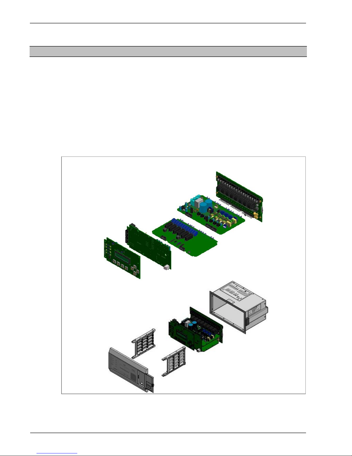
The P253 hardware comprises of the following main components:
• Housing, consisting of a front panel and connections at the rear
• Microcontroller module
• Analogue input module
• Digital input module
• Digital output module
• Communication module
• Power supply unit
• Human machine interface (HMI) module
Figure 1: P253 general assembly
Page 27

P50 Agile P253
3 Hardware Design
P253/EN M/C
3-5
2.1 Overview of Hardware Design
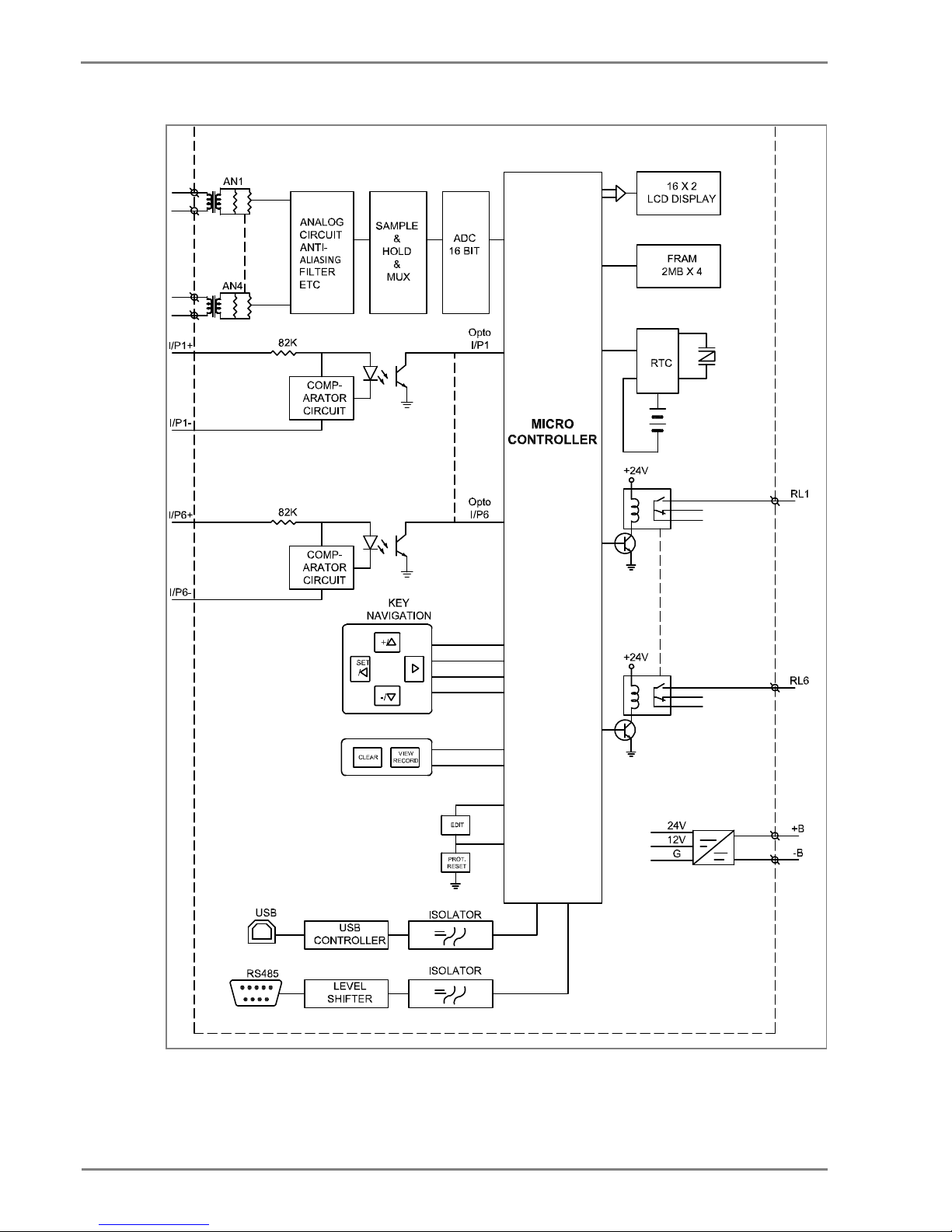
The P253 hardware design overview is explained with the help of the schematic diagram. The P253
hardware consists of three sets of internal Current Transformers (CTs). These internal CTs are
designed to cater to protection & metering requirements. Dedicated CT is available for the earth fault
protection requirements. The relay also has provision for the built-in SMPS unit which accepts power
supply input of 24-230 V AC/DC from external source and outputs 12 V and 24 V DC for internal
circuitry. The current signals acquired as analogue inputs get pr ocessed through operational amplifier,
filter circuit, multiplexer, ADC (Analog to digital converter) and finally fed to CPU.
The CPU design is a hybrid of the digital signal process or (DSP) and high speed microcontroller which
runs complex algorithm for deriving the fundamental & harmonic component from the input current
signals. The digital inputs and outputs modules are designed to interface the monitoring, control and
protection signals through optically isolated circuit as per the field requirements. The other peripherals
modules like 16x2 LCD display, feather touch keys, USB and RS485 communication interfaces,
battery backup for RTC and built in memory circuits are int egrated as per the schematic diagram and
enclosed in the IP-52 enclosure.
Page 28
3 Hardware Design
P50 Agile P253253
3-6
P253/EN M/C
E00276
Figure 2: Hardware design overview
Page 29
P50 Agile P253
3 Hardware Design
P253/EN M/C
3-7
2.2 Microcontroller with DSP Module
The hardware is designed around 32 bit controller housed in small 100 pin SMD package. It is a high
speed fix point controller having MIPS’s M4K® 32-bit core with 5-stage pipeline capable of operating
up to 80 MHz.This controller is referred to as MCU (Microcontroller unit).
2.2.1 Microcontroller Module (processor board) Features
• 512K Flash memory (plus an additional 12 KB of Boot Flash)
• 128K on chip SRAM memory
• Multiple interrupt vectors with individually programmable priority
• Fail-Safe Clock Monitor mode
• Configurable Watchdog Timer with on-chip Low-Po wer RC oscillator for reliable operation
• Internal 8 MHz and 32 kHz oscillators
• Six UART modules with:
• RS-232, RS-485, USB and LIN support
• Four SPI modules
• Five I2C™ modules
• Hardware Real-Time Clock and Calendar (RTCC)
• Five 16-bit Timers/Counters
2.3 Microcontroller and Analog Measurement
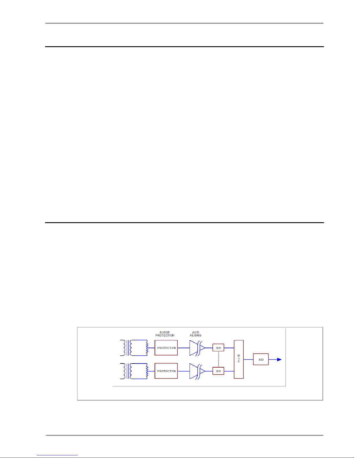
P253 hardware supports 4 analog inputs. The relay hardware uses an external 16 bit ADC converter
with capability to sample 8 signals simultaneously to avoid any phase angle error and achieve higher
accuracy. In P253, only 4 channels of ADC converter are used. This external ADC can measure input
in a range of – 10 V to +10 V. The ADC interface uses a SPI serial interface to avoid any software
delays. The MCU continuously monitors different analog signals like line and E/F currents through
CTs, multiplexer and ADC.
The relay is designed for 5 amp and 1 amp CT secondary cu rr ent signal. These inputs are further
scaled down to low voltage signal by using an internal cur rent and transformer. The internal current
transformer converts nominal current signal to 3.3 mA. These analog signals are then passed through
protection circuit, anti aliasing filter and amplifier which scales analogue signal to required ADC range.
This anti aliasing filter blocks all high frequency components and surges to avoid measurement error.
The sample and hold (S/H) circuit and multiplexer sample all analog signals at same instant to avoid
and phase angle error and give maximum accuracy.
V00277
Figure 3: Analog signal processing
Page 30
3 Hardware Design
P50 Agile P253253
3-8
P253/EN M/C
The MCU acquires analog values at the rate of 16 sam pl es per cycle. Digital signal processing (DSP)
performs powerful numerical algorithms which converts this signal in to equivalent vectors. Once the
signal is converted into vectors, number of parameters are derived from it such as phase currents (Ia,
Ib, Ic), positive sequence current (I1) and negative sequence current (I2). The MCU also calculates
harmonic contents of the current signals (actual harmonics depend upon type of relay). All
measurements are tuned to fundamental frequency i.e. 50 Hz or 60 Hz, so that the relay will remain
stable during distorted waveform generated by modern electronics load.
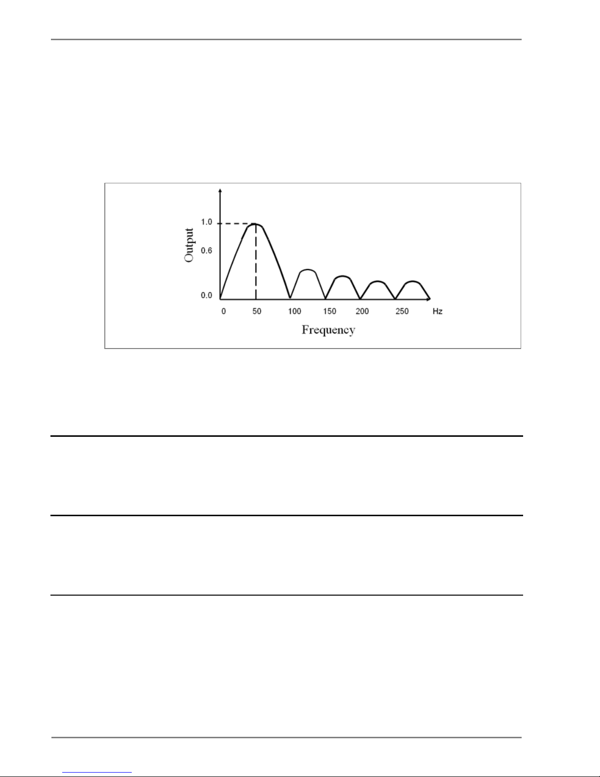
The typical frequency response of tuned filter for 50 Hz is shown in figure 4.
V00278
Figure 4: Frequency response of tuned filter for 50 Hz
The measurement is totally immune to all higher harm onics which makes relay operation reliable. All
these measured values are then used for different prot ect i on functions such as over current/Earth
Fault and negative phase sequences. The actual prot ection function depends on type of relay and
described in the rest of the document.
2.4 Digital Input/Output Module
This module supports 6 numbers of Digital input DI and 6 number s of Digital output DO channels for
acquiring filed signals or controlling field devices respectively. The DIs are isolated f rom other circuits
by using Opto isolators. The threshold voltage at which Opt o coupler turns ON is controlled by
comparator based on the voltage range selected duri ng device ordering.
2.5 Power Supply Module
The power supply module is a designed using modern PWM based switching mode technique. It
converts input supply to the 12 V and 24 Vdc low voltage su ppl y for relay electronics and control
circuit. It also provides necessary isolation from input power supply. The normal operating voltage
range is 24 V – 230 VAC/DC.
2.6 Communication Module
The P253 supports 2 numbers of isolated ports for communication.
• (a) USB port provided on front of the relay
• (b) RS 485 (2 wired) port provided on the rear side of relay.
The relay can be accessed using the P50 Agile Configurator. Rear port supports open protocols like
IEC60870-5-103/MODBUS or DNP3.0 (ordering option) and is used for external communication.
Page 31

P50 Agile P253
3 Hardware Design
P253/EN M/C
3-9
2.7 Human Machine Interface Module
The HMI module is provided with 16x2 LCD, 8 numbers of soft feather touch keys and 8 numbers of
LEDs for indication. The cover at right side of the fron t panel houses following:
• Female USB connector
• Serial number of relay
• Model number of relay
• Voltage and Current ratings
Figure 5: Front panel of P253 relay
Page 32

3 Hardware Design
P50 Agile P253253
3-10
P253/EN M/C
Page 33

P50 Agile P253
4 Front Panel
P253/EN M/C
4-1
FRONT PANEL
CHAPTER 4
Page 34

4 Front Panel
P50 Agile P253
4-2
P253/EN M/C
Page 35

P50 Agile P253
4 Front Panel
P253/EN M/C
4-3
1 CHAPTER OVERVIEW
This chapter consists of the following sections:
1
Chapter Overview
2 Front Panel
2.1 User Interface
2.1.1 LCD Display
2.1.2 Touch Keys
2.1.3 LEDs
2.1.4 RS 485 Port
2.1.5 USB Port
Page 36

4 Front Panel
P50 Agile P253
4-4
P253/EN M/C
2 FRONT PANEL
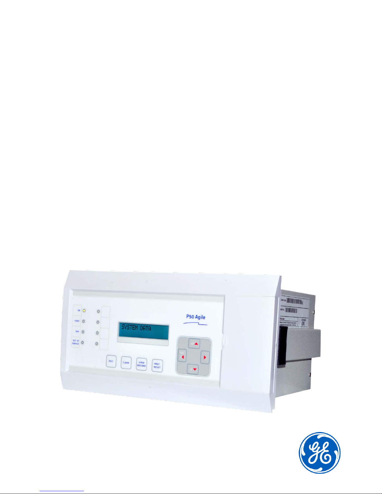
Figure 1: Front panel
SL no Label Function
1 ON
The green LED indicates that the IED is in correct working order. T he gr een LE D should be ON
at all times. If there is an error in the hardware or software t he LE D will turn red.
2
START
The amber LED flashes when the IED registers an alarm. This can be triggered by a fault or an
event or maintenance record. The LED will flash until the alarms have been accepted (read).
Press the VIEW RECORD function key and it will change to ON. When the alarms have been
cleared, press the CLEAR key and the LED will switch OFF.
3 TRIP
The red LED switches ON when the IED issues a trip signal. When the faults have been cleared
,
press the CLEAR key and the LED will switch OFF.
4
OUT OF SERVICE
The amber LED flashes when the IED's protection is unavailable (eg. Setting Error, ADC Error
detected by unit’s self-test etc).
5
L5
Programmable dual colour LED
6 L6 Programmable dual colour LED
7 L7 Programmable dual colour LED
8 L8 Programmable dual colour LED
9
LCD Display
The LCD display is used to view the settings and parameters of the relay.
10
EDIT
Feather touch key to edit parameter settings.
11
CLEAR
Feather touch key to clear the fault LED indications.
Also used to discard the setting changes.
12
VIEW RECORD
Feather touch key to view fault records.
13
PROT. RESET
Feather touch key to reset the hardware. This key should be be used alongside the EDIT key.
The relay will reboot when ‘PROT. RESET’ + EDIT are pressed simultaneously.
14
SET
/ ◄
Feather touch key SET to save the settings and /◄ is used for navigating through the
menus/submenus.
15 + /▲
Feather touch key [+] is used to INCREASE the values and [▲] is used to change the menu
level or change between settings in a particular menu.
16 - /▼ Feather touch key [-] is used to DECREASE the values and [▼] is used to change the menu
level or change between settings in a particular menu.
Page 37

P50 Agile P253
4 Front Panel
P253/EN M/C
4-5
SL no
Label
Function
17 ►
Feather touch key [►] is used to view the settings and to navigate through the menus and
submenus.
2.1 User Interface
2.1.1 LCD Display
A backlit LCD display of 16 x 2 characters is provided for param eter and setting display. It also
provides easy viewing of measurement, setting, f aul t records, date & time and error messages. The
backlit display will switch off automatically after 100 seconds if no key is pressed. The backlit display
will turn ON automatically if any tripping occurs.
2.1.2 Touch Keys
The function of the relay is controlled by the following key s on the front panel.
(+) key is used to INCREASE the values
(▲) key is used to change the menu level or change between settings in a particular menu.
SET key is used to save the settings
(◄) key is used for navigating through the menus/submenus.
(►) key is used to view the settings and to navigate through the menus and submenus.
(-) key is used to DECREASE the values
(▼) key is used to change the menu level or change between settings in a particular menu.
EDIT key is used to edit the setting
CLEAR key is used to clear the fault LED indications. This key is also used to discard the setting
changes.
VIEW RECORD key is used to view the Fault, Maintenance and Event Records.
PROT. RESET key is used for Hardware reset. This key is interlocked with the EDIT key. This
key is not required to be pressed in normal operation, but is used to reset the hardware of relay
during a relay firmware update.
Note: If you edit the settings you have 100 s to make the changes. After 100 s the display will reset itself
and return to the Main Menu.
Page 38

4 Front Panel
P50 Agile P253
4-6
P253/EN M/C
2.1.3 LEDs
The P253 relay has 8 high-intensity LEDs for easy identification of fault type and ease of user
interface.
SL no
Label
Function
LED 1
ON
The green LED indicates that the IED is in correct working order. The gr een LE D should be ON
at all times. If there is an error in the hardware or software t he LE D will turn red.
LED 2
START
The amber LED flashes when the IED registers an alarm. This can be triggered by a fault or an
event or maintenance record. The LED will flash until the alarms have been accepted (read).
Press the VIEW RECORD function key and it will change to ON. When the alarms have been
cleared, press the CLEAR key and the LED will switch OFF.
LED 3
TRIP
The red LED switches ON when the IED issues a trip signal. When the faults have been cleared,
press the CLEAR key and the LED will switch OFF.
LED 4
OUT OF SERVICE
The amber LED flashes when the IED's protection is unavailable (eg. Setting Error, ADC Error
detected by unit’s self-test etc).
LED 5,6,7,8
-
Programmable dual colour LED
2.1.4 RS 485 Port
The RS485 port is provided at the rear of relay (near to terminal block) for permanent SCADA
connectivity. The separate 5 Pin connector is used to avoid accidental connection of power wiring to
communication input. The RS485 port can be used to download Settings, Fault data, Live Event and
Disturbance Records.
2.1.5 USB Port
The USB port is situated on the front panel in the bottom right hand corner, and can be accessed by
opening the flap on the front of the relay. This port is used to communicate with a locally connected
PC.
It has three main purposes:
• Transferring settings information to/from the P C from/to the device.
• Downloading firmware updates.
• Downloading relay data for analysis.
The port is intended for temporary connection during testing, installation and commissioning. It is not
intended to be used for permanent SCADA communicati ons.
You can connect the unit to a PC with a USB cable up to 15 m in l engt h.
The USB port includes a USB full-speed function controller, USB transceiver, oscillator, EEPROM, and
synchronous serial data bus (UART). No other extern al US B components are required.
For configuration/setting the appropriate ‘config port’ has to be selected from the SYSTEM DATA
menu.
Page 39

P50 Agile P253
4 Front Panel
P253/EN M/C
4-7
Figure 2: USB port
Page 40

4 Front Panel
P50 Agile P253
4-8
P253/EN M/C
Page 41

P50 Agile P253
5 Configuration
P253/EN M/C
5-1
CONFIGURATION
CHAPTER 5
Page 42

5 Configuration
P50 Agile P253
5-2
P253/EN M/C
Page 43

P50 Agile P253
5 Configuration
P253/EN M/C
5-3
1 CHAPTER OVERVIEW
This chapter consists of the following sections:
1
Chapter Overview
2 Configuration
2.1 Changing the Settings
2.2 Password Entry
2.3 Menus
2.3.1 Default Display
2.3.2 Main Menu Contents
2.3.3 System Data Menu
2.3.3.1 View / Edit Settings
2.3.4 View Records Menu
2.3.4.1 View Records Menu Contents
2.3.4.2 View Fault Records
2.3.4.3 View Event Records
2.3.4.4 View Maintenance Records
2.3.4.5 View Alarm Records
2.3.5 Measurement Menu
2.3.5.1 View Contents- Measurement 1 Submenu
2.3.5.2 View Contents- Measurement 2 Submenu
2.3.6 CB Control Menu
2.3.6.1 View / Edit Settings (if all settings are disabled)
2.3.6.2 View / Edit settings (if all settings are enabled)
2.3.7 Date and Time Menu
2.3.7.1 Edit Settings (if the settings are disabled)
2.3.7.2 Edit Settings (if the settings are enabled)
2.3.8 Configuration Menu
2.3.8.1 View / Edit Settings
2.3.9 Transformer Ratios Menu
2.3.9.1 View / Edit Settings
2.3.10 Record Control Menu
2.3.10.1 View / Edit Settings
2.3.11 Communication Menu
2.3.11.1 View / Edit Settings
2.3.12 I/O Configuration Menu
2.3.12.1 View / Edit Settings
2.3.12.2 List of the submenus for Relay Output, LEDs and AND Logic configuration
2.3.13 O/P Relay Configuration Menu
2.3.13.1 View / Edit Settings
2.3.14 Disturbance Record Menu
2.3.14.1 View / Edit Settings
2.3.15 Commissioning Test Menu
2.3.15.1 View / Edit Settings
2.3.16 Group 1 Menu
2.3.16.1 Edit Settings
2.3.16.2 Group 1 –System Configuration Submenu
2.3.16.3 Group 1 – Overcurrent Submenu
2.3.16.4 Group 1 –Negative Sequence Overcurrent Submenu
2.3.16.5 Group 1 – Earth Fault 1 Submenu
2.3.16.6 Group 1 – Earth Fault 2 Submenu
2.3.16.7 Group 1 –Thermal Overload Submenu
2.3.16.8 Group 1 – Loss of Load Submenu
2.3.16.9 Group 1 –CB Fail Submenu
2.3.16.10 Group1 –Stall Detection Submenu
Page 44

5 Configuration
P50 Agile P253
5-4
P253/EN M/C
2.3.16.11 Group1 –Limit Nb Starts Submenu
2.3.17 Group 2 Menu
2.3.17.1
Edit Settings
2.4 Configuration Flowcharts
2.4.1 Main Menu
2.4.2 View and Edit Settings
2.4.3 View System Data Menu Settings
2.4.4 Records Menu
2.4.4.1 View Records
2.4.4.2 View Fault Records
2.4.4.3 View Event Records
2.4.4.4 View Maintenance Records
2.4.4.5 View Alarm Records
2.4.5 Measurement Menu
2.4.5.1 View Measurement 1 Submenu
2.4.5.2 View Measurement 2 Submenu
2.4.6 CB Control Menu
2.4.6.1 View / Edit Settings (if all settings are disabled)
2.4.6.2 View / Edit Settings (if all settings are enabled)
2.4.7 Date and Time Menu
2.4.7.1 View / Edit Settings (if all settings are disabled)
2.4.7.2 View / Edit Settings (if all settings are enabled)
2.4.8 Configuration Menu
2.4.8.1 View / Edit Settings
2.4.9 Transformer Ratios Menu
2.4.9.1 View / Edit Settings
2.4.10 Record Control Menu
2.4.10.1 View / Edit Settings
2.4.11 Communication Menu
2.4.12 View / Edit Settings
2.4.13 I/O Configuration Menu
2.4.14 View / Edit Settings
2.4.15 O/P Relay Configuration Menu
2.4.15.1 View / Edit Settings
2.4.16 Disturbance Record Menu
2.4.16.1 View / Edit Settings
2.4.17 Commissioning Test Menu
2.4.17.1 View / Edit Settings
2.4.18 Group 1 Menu
2.4.18.1 View / Edit Settings
2.4.18.2 Group 1- System Configuration Submenu
2.4.18.3 Group 1- Overcurrent Submenu
2.4.19 Group 1- Negative Sequence Overcurrent Menu
2.4.19.1 View / Edit Settings (If setting is disabled)
2.4.19.2 View / Edit Settings (For all types of IEC curves)
2.4.19.3 View / Edit Settings (For all types of IEEE curves)
2.4.19.4 View / Edit Settings (For DT)
2.4.20 Group 1- Earth Fault 1 Submenu
2.4.20.1 View / Edit Settings (If setting is disabled)
2.4.20.2 View / Edit Settings (For all types of IEC curves)
2.4.20.3 View / Edit Settings (For all types of IEEE curves)
2.4.20.4 View / Edit Settings (For DT)
2.4.21 Group 1- Earth Fault 2 Submenu
2.4.21.1 View / Edit Settings (If setting is disabled)
2.4.21.2 View / Edit Settings (For all types of IEC curves)
2.4.21.3 View / Edit Settings (For all types of IEEE curves)
2.4.21.4 View / Edit Settings (For DT)
Page 45

P50 Agile P253
5 Configuration
P253/EN M/C
5-5
2.4.22 Group 1- Thermal Overload Submenu
2.4.22.1 View / Edit Settings (If setting is disabled)
2.4.22.2 View / Edit Settings (If setting is disabled)
2.4.22.3 View / Edit Settings (If setting is enabled)
2.4.23 Group 1- Loss of Load Submenu
2.4.23.1 View / Edit Settings (If setting is disabled)
2.4.23.2 View / Edit Settings (If the setting is enabled)
2.4.24 Group 1- CB Fail Submenu
2.4.24.1 View / Edit Settings (If setting is disabled)
2.4.24.2 View / Edit Settings (If setting is enabled)
2.4.25 Group 1- Stall Detection Submenu
2.4.25.1 View / Edit Settings (If setting is disabled)
2.4.25.2 View / Edit Settings (If setting is enabled)
2.4.26 Group 1- Limit Nb Starts Submenu
2.4.26.1 View / Edit Settings (If setting is disabled)
2.4.26.2 View / Edit Settings (If setting is enabled)
2.4.27 Group 2 Menu
2.4.27.1 View / Edit Settings
Page 46

5 Configuration
P50 Agile P253
5-6
P253/EN M/C
2 CONFIGURATION
Each product has different configuration parameter s according to the functions it has been
designed to perform. There is, however, a common m ethodology used across the entire product
to set these parameters.
This chapter describes an overview of this common methodology, as well as providing concise
instructions of how to configure the device.
Using the HMI you can:
• Display and modify settings
• View the digital I/O signal status
• Display measurements
• Display fault records
• Reset fault and alarm indications
The keypad provides full access to the device functionality by means of a range of menu options.
Information is displayed on the LCD.
Figure 1: P253 menu/function keys
Page 47

P50 Agile P253
5 Configuration
P253/EN M/C
5-7
2.1 Changing the Settings
SYSTEM DATA
Step 1: Press the (4) key to move to the next option.
Language
English
Step 2: Press the (- /6) key to move to the next option till the relay
displays CB Open/Close setting
: : :
: : :
CB Open/Close
Open
Step 3:
Once the relay displays this option, press
EDIT
key to edit the
setting.
Password = 0001
[All editable settings are password protected. So when the EDIT key is
pressed, it will display the password and the settable number/text will
start blinking].
Step 4: Enter the password by using the (+ /5) or the (- /6) key. The
Password is four (4) digits alpha numeric.
Password = 0000
** Password OK **
Step 5: After editing the Password, press the EDIT key, the **Password
OK** message is displayed and settable number/text will start blinking
and the relay will move to the next option.
Note: When the password is set, modification can be done in any
settings within 15 minutes. After the lapse of 15 minutes, the relay will
once again ask to re-enter the password.
CB Open/Close
Open
Step 6: By using the (+ /5) or (- /6) key, the desired selection can be
set as shown in the display.
CB Open/Close
Close
Step 7:
After setting, press the
EDIT
key, the text will stop blinking and
move to the next option.
Step 8: Press the (3) / (4) key, it will ask if you want to save the
settings and move to the next option.
SET For Save
CLEAR For Cancel
Step 9: When the SET key is pressed again, it will save the changes
and move to the next option.
SAVE Settings
This window will flash for a moment and the control will return to the
main menu.
Page 48

5 Configuration
P50 Agile P253
5-8
P253/EN M/C
SYSTEM DATA
Note: Press the CLEAR Key to DISCARD settings.
SET For Save
CLEAR For Cancel
Step 10: When the CLEAR key is pressed, it will discard the changes
and the relay will move to the next option.
DISCARD Settings
This window will flash for a moment and the control will return to the
main menu.
SYSTEM DATA
2.2 Password Entry
To modifiy the settings you will need password access. You will be asked for a password before
you can make any of the following changes. The defaul t password is 0000.
1. When you press the EDIT key a flashing cursor appears at the right most character field
of the password by default. Press the up or down cursor key s t o change each character.
2. Use the left and right cursor keys to move between the character fields of t he password.
3. Press the SET key to confirm the password. After entering a valid password the
Password OK message appears indicating that the password is correct. The user can
now start editing the settings. If the correct password has not been entered, the password
prompt page appears again. To stop this prompt press the CLEAR key.
4. A new password c an be set using the Password cell in the SYSTEM DATA menu.
5. If the keypad is inactive for 15 minutes the user will again be prompted for a password
entry.
Page 49

P50 Agile P253
5 Configuration
P253/EN M/C
5-9
2.3 Menus
2.3.1 Default Display
After Power ON or when the PROT.RESET + EDIT keys are pressed the relay will display the
following message.
P50 Agile P253
Motor Protect’n
This window will flash momentarily showing the following.
Relay Name: P50 Agile P253,
Relay Type : Motor Protection
Then the control will automatically move to next option.
ID = 1
SW = V1.04
This window will flash momentarily showing the following :-
Unit ID = 1
Software Version =V1.04
Then the control will automatically move to the default window.
SYSTEM DATA
2.3.2 Main Menu Contents
SYSTEM DATA
Password protected window for “SYSTEM DATA’’ setting i.e. Language,
Description, Model Number, Serial Number, Software Version,
Frequency, USB Address, USB Parity, USB Baud Rate, Password,
Active Group, Opto I/P Status, R elay O/P S tatus. CB Open/ Close, Opto
I/P and Config Port.
VIEW RECORDS
Menu to view Fault Record, Event Record, Maint Record and Alarm
records.
MEASUREMENTS
This menu displays the measurements values of various parameters
under submenu Measurement 1 and 2
Measurement 1 (i.e. Phase current, measured and derived earth
current, negative, positive phase sequence current and zero s equence
current) as per phase/earth C T ratio, rms value of phase current, BOC
(Breaker Operation Counter), TC (Trip Counter), BOT (Breaker
Operating Time), and
Measurement 2 (i.e. Thermal State, Load Current, T ime to Th Trip, Nb
of Th Trip, Last Start Time, Last St Current, Nb Hot St Allow, Nb Cold St
Allow, Time to Next St, Tot al Nb of Strt, Nb Emergency Rst and Motor
Run Time)
CB CONTROL
Password protected window for “CB CONTROL” settings
i.e. TCS
Alarm, TCS Timer, CB Open S ’vision (Enabled / Disabled), CB Open
Time, CB Open Alarm (Enabled / Disabled), CB Open Oper, CB Control
By, Close Pulse Time, Open Pulse Time and Emergency Rest. (Yes/No).
Page 50

5 Configuration
P50 Agile P253
5-10
P253/EN M/C
DATE AND TIME
Password protected window for “DATE AND TIME’’ settings i.e. Local
Time Enable, Local Time Offset. DST Enable, DST Offset, DST Start,
DST Start Day, DST Start Mont h, DST Start Mins, DST End, D ST End
Day, DST End Month, DST End Mins, RP Time Zone, S ET Hours, SET
Minutes, SET Seconds, SET Date, SET Month and SET Year.
CONFIGURATION
Password protected window for “CONFIGURATION’’ settings i.e.
Restore Defaults, Active Sett ings , Copy From, Copy To, S etting G roup 1
(Enabled/Disabled), Setting Group 2 (Enabled/Disabled), System Conf ig
(Enabled/Disabled), Overcurrent (Enabled/Disabled)
, Neg Sequence
O/C (Enabled/Disabled), E arth Fault 1 (Enabled/Disabled), Earth Fault 2
(Enabled/Disabled), Thermal Overlo ad (Enabled/Disabled), Loss of Lo ad
(Enabled/Disabled), CB Fail (Enabled/Disabled), Stall Detection
(Enabled/Disabled), Limit NB Starts (Enabled/Disabled), IFL, Measure’t
Setup, and Setting Values.
TRANS. RATIOS
Password protected window for
“TRANS. RATIO ’’
settings i.e Phase
CT Primary, Phase CT Sec’y, E/F CT Primary and E/F CT Secondary.
RECORD CONTROL
Password protected window for “RECORD CONTROL’’ settings i.e.
Clear Events (Yes/No), Clear F aults (Yes/No), Clear Dist Recs (Yes/No),
Clear Maint (Yes/No), Thermal Reset (Yes/No), Reset Nb Em Rst
(Yes/No), Reset Nb of St (Yes/No), Reset Motor RunT (Yes/No) and
Reset CB Data (Yes/No).
COMMUNICATION
Password protected window for
“COMMUNICATION’’
settings i.e. RP1
Address, RP1 Baud Rate, RP1 Parity and RP1 Timesync.
IO CONFIGURATION
Password protected window for “IO CONFIGURATION’’ settings i.e.
Relay, LED G, LED R, AND Logic and Opto I/P.
O/P RELAY CONFIG
Password protected window for “O/P RELAY CONFIGURATION’’
setting i.e. Contact HR/SR, O/P-1 Open Ti me, O/P -2 Open Time, O/ P-3
Open Time, O/P-4 Open Time, O/P -5 Op en T ime and O/P-6 Open Ti me,
LED G HR/SR, LED R HR/SR, ANDEQ A Op Time, ANDEQ A Rst Time,
ANDEQ B Op Time, ANDEQ B Rst Time, ANDEQ C Op Time, ANDEQ C
Rst Time, ANDEQ D Op Time and ANDEQ D Rst Time.
DISTURBANCE REC
Password protected window for
“DISTURBANCE RECORD”
setting i.e.
Trigger Position.
COMMISSION. TEST
Password protected window for “COMMISSIONING TEST” setting i.e.
Test Mode, Test Pattern, Contact Test and Test LEDs.
Page 51

P50 Agile P253
5 Configuration
P253/EN M/C
5-11
GROUP 1
Password protected window for
“GROUP 1’’
settings
i.e. SYSTEM
CONFIG, OVERCURRENT, NEG SEQUENCE O/C, EARTH FAULT 1,
EARTH FAULT 2, THERMAL OVERLOAD, LOSS OF LOAD, CB FAIL
STALL DETECTION and LIMIT NB STARTS.
Note: Group 1 settings will be seen only when it is enabled and set
under Active Settings in Configuration menu.
GROUP 2
Password protected window for “GROUP 2’’ settings
i.e. SYSTEM
CONFIG, OVERCURRENT, NEG SEQUENCE O/C, EARTH FAULT 1,
EARTH FAULT 2, THERMAL OVERLOAD, LOSS OF LOAD, CB FAIL
STALL DETECTION and LIMIT NB STARTS.
Note: Group 2 settings will be seen only when it is enabled and set
under Active Settings in Configuration menu.
2.3.3 System Data Menu
2.3.3.1 View / Edit Settings
SYSTEM DATA
Password protected window for “SYSTEM DATA’’ settings i.e.
Language, Description, Model Number, Serial Number, Software
Ve
rsion, Frequency, USB Address, USB Parity, USB Baud Rate,
Password, Active Group, Opto I/P Status, Relay O/P Status. CB
Open/Close, Opto I/P and Config Port.
Language
English
Read-only
This window shows user interface is in English Language.
Description
P50 Agile P253
Read-only
This window shows Description of the relay.
Model Number
P253121A1A0010A
Read-only
This window shows the Model Number of the relay.
Serial Number
xxxP253xxxx
Read-only
This window shows the Serial Number of the relay.
Software Version
P253_1__1_0V1.04
Read-only
This window shows the Software Version of the relay.
Frequency
50Hz
Editable setting
This window shows the setting for System Frequency.
The desired Frequency can be selected to either 50 / 60 Hz.
Page 52

5 Configuration
P50 Agile P253
5-12
P253/EN M/C
USB Address
1
Read-only
This window shows the USB Address.
USB Parity
None
Read-only
This window shows the USB Parity.
USB Baud Rate
57600
Read-only
This window shows the USB Baud Rate
Password
****
Editable setting
This window is for setting the new Password of the relay. The desired
alpha numeric case sensitive password can be selected from 0000 to
zzzz and each digit can be set i.e. 0 to 9 / A to Z / a to z.
Active Group
Group 1
Read-only
This window shows the Active Group selected in configuration.
Opto I/P 654321
Status 000000
Read-only
This window shows the Opto Input status.
Relay O/P 654321
Status 000000
Read-only
This window shows the Relay Output status.
CB Open / Close
No operation
Editable setting
This window allows selection of the desired CB operation i.e. Open,
Close and No operation.
Opto I/P
DC
Editable setting
This window allows selection of voltage input type for the Opto I/P i.e.
AC / DC
Config Port
USB
Editable setting
This window allows selection of the Configuration Port of the relay
i.e. USB / RP
Page 53

P50 Agile P253
5 Configuration
P253/EN M/C
5-13
2.3.4 View Records Menu
2.3.4.1 View Records Menu Contents
VIEW RECORDS
Menu to view Fault Record, Event Record, Maint Record and Alarm
record.
Fault Record
This window is to view the Fault Record
Event Record
This window is to view the Event Record
Maint Record
This window is to view the Maint Record
Alarm Record
This window is to view the
Alarm Record
2.3.4.2 View Fault Records
VIEW RECORDS
Menu to view Fault Record, Event Record, Maint Record and Alarm
record.
Fault Record
This window shows the Fault Record
Fault Num = 1
This window shows the Fault Number of latest fault.
I>1: I<:
IN1>1: IN2>1: I2>1:
This window displays trip flag of stage 1: O/C, E/F-1 and E/F-2, Neg
Sequence O/C, Under Current, Thermal Trip.
Note: This window is seen when relay operates for respective protection
function.
Page 54

5 Configuration
P50 Agile P253
5-14
P253/EN M/C
I>2:
IN1>2: IN2>2: I2>2:
This window displays trip flag of stage 2: O/C, E/F-1 and E/F-2, Neg
Sequence O/C, Lock Rotor, Stall trip.
Note: This window is seen when relay operates for respective protection
function.
I>3:
IN1>3: IN2>3: I2>3:
This window displays trip flag of stage 3: O/C, E/F-1 and E/F-2, Neg
Sequence O/C, Prolong Start.
Note: This window is seen when relay operates for respective protection
function.
S1 S3 S5 CBF
S2 S4 S6 EXT TR
This window displays status flag (S1 – Opto Input 1, S2 – Opto Input 2,
S3 – Opto Input 3, S4 – Opto Input 4, S5 – Opto Input 5, and S6 – Opto
Input 6, CBF – CB Fail, EXT TR – External Trip)
Note: This window is seen when status flag operates
ia = 0.00 A
ib = 0.00 A
This window displays secondary fault current values.
ic = 0.00 A
in1= 0.00 A
This window displays secondary fault current values.
in2 = 0.00 A
i2 = 0.00 A
This window displays secondary fault current values.
i1 = 0.00 A
i0 =0.00
This window displays secondary fault current values.
Thermal State
0%
This window displays Thermal State.
Trip Counter
0
This window displays Trip counter.
Trip Timing (Sec)
0.000
This window displays Trip time.
Page 55

P50 Agile P253
5 Configuration
P253/EN M/C
5-15
17/11/14
16:15:30.225
This window displays date & time of fault.
2.3.4.3 View Event Records
VIEW RECORDS
Menu to view Fault Record, Event Record, Maint Record and Alarm
record.
Fault Record
This window shows the Fault Record
Event Record
This window shows the Event Record
Event Num = 1
This window shows the Event number of latest event.
By using the (+ /5) or (- /6) key, the relay will scroll between Event
numbers 1 to 512.
Dt: 21/02/2014
Tm: 16:15:30:225
This window will show date & time of Event.
Event Num = 1
Trip IN1>
This window shows the latest Event and Event number.
2.3.4.4 View Maintenance Records
VIEW RECORDS
Menu to view Fault Record, Event Record, Maint Record and Alarm
record.
Fault Record
This window shows the Fault Record
Page 56

5 Configuration
P50 Agile P253
5-16
P253/EN M/C
Event Record
This window will show Event Record
Maint Record
This window will show Maintenance Record contents
Main’t Rec Num =
1
This window shows Maintenance Record 1
Errorcode : 0004
RTC Error
This window shows the contents of the Maintenance Record 1.
07/06/2014
17:20:30.596
This window shows the date and time of error.
2.3.4.5 View Alarm Records
VIEW RECORDS
Menu to view Fault Record, Event Record, Maint Record and Alarm
record.
Fault Record
This window will show the Fault Record
Event Record
This window will show Event Record
Maint Record
This window will show Maintenance Record
Page 57

P50 Agile P253
5 Configuration
P253/EN M/C
5-17
Alarm Record
This window will show Alarm Record
TCS Al a rm
This window shows latest alarm.
24/09/2014
12:35:40:025
This window shows the date and time of alarm.
2.3.5 Measurement Menu
2.3.5.1 View Contents- Measurement 1 Submenu
MEASUREMENTS
Menu to view the Measurement 1 & Measurement 2
Measurement 1
Submenu to view following measurements :
Phase current, Measured and derived earth c
urrent, Negative and
Positive phase sequence curr ent and zero sequence curr ent) as per CT
Primary and Secondary current s election, RMS value of Phase Current,
BOC (Breaker Operation Counter), TC (Trip Counter), BOT (Breaker
Operating Time),
IA = 0 A
IB = 0 A
This window shows primary value of current in phase A and B taking in
to account phase CT ratio.
IC = 0 A
IN1 = 0 A
This window shows primary value of current in phase C and measured
earth current taking in account phase CT and earth CT ratio respectively.
IN2 = 0 A
I0 = 0 A
This window shows primary value of internally derived earth current and
zero sequence current.
I1 = 0 A
I2 = 0 A
This window shows primary value of positive sequence current and
negative sequence current.
Page 58

5 Configuration
P50 Agile P253
5-18
P253/EN M/C
ia = 0.00 A
ib = 0.00 A
This window shows secondary value of current in phase A and phase B.
ic = 0.00 A
in1 = 0.00 A
This window shows secondary value of current in phase C and
measured earth current.
in2 = 0.00 A
i0 = 0.00 A
This window shows secondary value of internally derived earth current
and zero sequence current.
i1 = 0.00 A
i2 = 0.00 A
This window shows secondary value of positive sequence current and
negative sequence current.
Irms A = 0.00 A
Irms B = 0.00 A
This window shows secondary value of RMS current in phase A and
Phase B.
Irms C = 0.00 A
BOC : 0
This window shows secondary value of RMS current in phase C and
Breaker operation counter.
TC : 0
BOT : 0 msec
This window shows Trip Counter and Breaker Operating Time
2.3.5.2 View Contents- Measurement 2 Submenu
MEASUREMENTS
This menu is to view the Measurement 1 & Measurement 2
Measurement 1
Submenu to view measurements related to phase current, earth current,
breaker operation, trip counter and breaker operating time.
Page 59

P50 Agile P253
5 Configuration
P253/EN M/C
5-19
Measurement 2
Submenu to view measurements related to motor :
Thermal State, Load Current, Time to Th Trip, Nb of Th Trip, Last Start
Time, Last St current, Nb Hot st Allow, Nb Cold St Allow, Time to Next
St, Total Nb of Strt, Nb of Emergency Rst, and Motor Run Time.
Thermal State
0 %
This window shows Thermal state o f the motor
Load Current
0 %
This window shows load current value in % (maximum value of three
phase currents in % of IFL setting)
Time to Th Trip
0 S
This window shows Time to Thermal Trip.
Nb of Th Trip
0
This window shows counter for number of Thermal Trip.
Last Start Time
0.00 S
This window shows the duration of the last start.
Last St Current
0.00 A
This window shows the current value of last start.
Nb Hot St Allow
2
This window shows the number of motor hot start allowed
Nb Cold St Allow
3
This window shows the number of motor cold start allowed
Page 60

5 Configuration
P50 Agile P253
5-20
P253/EN M/C
Time to Next St
0 S
This window shows time before permitted start
Total Nb of Strt
0
This window shows the number of starts of the motor
Nb Emergency Rst
0
This window shows number of emergency starts
Motor Run Time
0.000 hrs
This window shows total motor running hours
2.3.6 CB Control Menu
2.3.6.1 View / Edit Settings (if all settings are disabled)
CB CONTROL
Password protected window for “CB CONTROL” settings: TCS Alarm,
TCS Timer, CB Open S’visio n , CB Open Time, CB Open Alarm , C B
Open Oper, CB Control By, Close Plus Time, Open pulse Time and
Emergency Rest.
TCS Al a rm
NO
Editable setting
By using the (+ /5) or (- /6) key, TCS Alarm can be set as Yes / No.
CB Open S’vision
Disabled
Editable setting
By using the (+ /5) or (- /6) key , CB Open Supervision can be
Enabled or Disabled.
CB Open Alarm
Disabled
Editable setting
By using the (+ /5) or (- /6) key, CB Open Alarm can be Enabled or
Disabled.
CB Control by
Disabled
Editable setting
By using the (+ /5) or (- /6) key, CB Control By can be set as
Disabled / Local / Remote / Local + Remote.
Page 61

P50 Agile P253
5 Configuration
P253/EN M/C
5-21
Emergency Rest
No
Editable setting
By using the (+ /5) or (- /6) key, Emergency Restar t can be set as
Yes / No.
2.3.6.2 View / Edit settings (if all settings are enabled)
CB CONTROL
Password protected window for “CB CONTROL” settings:
TCS Alarm, TCS Timer, CB O pen S ’v ision (Enabled/Disabled), CB O pen
Time, CB Open Alarm (Enabled/Disabled), CB Open Oper, CB Control
By, Close Plus Time, Open Pulse Time and Emergency Rest (Yes/No).
TCS Al a rm
Yes
Editable setting
By using the (+ /5) or (- /6) key, TCS Alarm can be set as Yes / No.
TCS Timer
5.00S
Editable setting
By using the (+ /5) or (- /6) key, TCS Timer can be set. The setting
range is from 0.1s to 10s in steps of 10ms.
CB Open S’vision
Enabled
Editable setting
By using the (+ /5) or (- /6) key, CB Open Supervision can be
Enabled or Disabled.
CB Open Time
0.30S
Editable setting
By using the (+ /5) or (- /6) key, CB Open Time can be set. The
setting range is from 50ms to 1s in steps of 10ms
CB Open Alarm
Enabled
Editable setting
By using the (+ /5) or (- /6) key, CB Open Alarm can be Enabled or
Disabled.
CB Open Oper
2000
Editable setting
By using the (+ /5) or (- /6) key, CB Open operations can be set. The
setting range is from 1 to 30000 in steps of 1.
CB Control by
Local + Remote
Editable setting
By using the (+ /5) or (- /6) key, CB Control By can be set as
Disabled/Local/Remote /Local + Remote.
Page 62

5 Configuration
P50 Agile P253
5-22
P253/EN M/C
Close Pulse Time
0.50S
Editable setting
By using the Plus / Up arrow key (+ /5) or the Minus / Down arrow key
(- /6) key, the desired Close Pulse Time can be set. The setting range
is from 0.1s to 50s in steps of 0.01s
Open Pulse Time
0.50S
Editable setting
By using the Plus / Up arrow key (+ /5) or the Minus / Down arrow key
(- /6) key, the desired Open Pulse Time can be set. The setting range
is from 0.1s to 50s in steps of 0.01s
Emergency Rest
Yes
Editable setting
By using the (+ /5) or (- /6), Emergency Restart can be set as Yes /
No
2.3.7 Date and Time Menu
2.3.7.1 Edit Settings (if the settings ar e d isabled)
DATE AND TIME
Password protected window for “DATE AND TIME” settings:
Local Time Enable, Local Time Off set, DST Enable, DST Offset, DST
Start, DST Start Day, DST Start Month, DST Start minutes, DST End,
DST End Day, DST End Month, DST End minutes, RP Tim e Zone, SET
Hours, SET Minutes, SET Seconds, SET Date, SET Month and SET
Year.
Tm: 17:21:50
Dt : 14/11/14 Fri
Read-only
This window shows the set Date & Time
Local Time Enable
Disabled
Editable setting
By using the (+ /5) or (- /6) key, Local Time Enable can be set as
Disabled / Fixed / Flexible.
DST Enable
Disabled
Editable setting
By using the (+ /5) or (- /6) key, DST Enable can be set as
Enabled/Disabled.
RP Time Zone
Local
Editable setting
By using the (+ /5) or (- /6) key, RP Time Zone can be set as Local /
UTC
Page 63

P50 Agile P253
5 Configuration
P253/EN M/C
5-23
SET Hours
17
Editable setting
By using the (+ /5) or (- /6) key, the desired SET Hours can be set.
The setting range is from 00 to 23 in steps of 1.
SET Minutes
21
Editable setting
By using the (+ /5) or (- /6) key, the desired SET Minutes can be set.
The setting range is from 00 to 59 in steps of 1.
SET Seconds
50
Editable setting
By using the (+ /5) (- /6) key, the desired SET Seconds can be set.
The setting range is from 00 to 59 in steps of 1.
SET Date
14
Editable setting
By using the Plus / Up arrow key (+ /5) or the Minus / Down arrow key
(- /6) key, the desired SET Date can be set. The setting range is from 1
to 31 in steps of 1.
SET Month
11
Editable setting
By using the (+ /5) or (- /6) key, the desired SET Month can be set.
The setting range is from 1 to 12 in steps of 1.
SET Year
14
Editable setting
By using the (+ /5) or (- /6) key, the desired SET Year can be set. The
setting range is from 00 to 99 in steps of 1.
2.3.7.2 Edit Settings (if the settings are en abled)
DATE AND TIME
Password protected window for “DATE AND TIME” settings:
Local Time Enable, Local Time Offset, DST Enable, DST Offset, DST
Start, DST Start Day, DST Start Month, DST Start minutes, DST End,
DST End Day, DST End Month, DST End minutes, RP Time Zone, SET
Hours, SET Minutes, SET Seconds, SET Date, SET Month and SET
Year.
Tm: 17:21:50
Dt : 14/11/14 Fri
Read-only
This window shows the set Date & Time
Local Time Enable
Fixed
Editable setting
By using the (+ /5) or (- /6) key, Local Time Enable can be set as
Disabled / Fixed / Flexible.
Page 64

5 Configuration
P50 Agile P253
5-24
P253/EN M/C
Local Time Offset
0 Mins
Editable setting
By using the (+ /5) or (- /6) key, Local Time Offset can be set. The
setting range is from -720 mins to 720 mins in steps of 15 mins
DST Enable
Enabled
Editable setting
By using the (+ /5) or (- /6) key, DST Enable can be
Enabled/Disabled.
DST Offset
60 Mins
Editable setting
By using the (+ /5) or (- /6) key, DST Offset can be set as 30Mins /
60Mins.
DST Start
Last
Editable setting
By using the (+ /5) or (- /6) key, DST Start can be set as First /
Second/ Third / Fourth / Last.
DST Start Day
Sunday
Editable setting
By using the (+ /5) or (- /6) key, DST Start Day can be set from
Sunday to Saturday.
DST Start Month
March
Editable setting
By using the (+ /5) or (- /6) key, DST Start Month can be set from
January to December
DST Start Mins
60 Mins
Editable setting
By using the (+ /5) or (- /6) key, DST Start minutes can be set. The
setting range is from 0 to 1425 mins in steps of 15 mins.
DST End
Last
Editable setting
By using the (+ /5) or (- /6) key, DST End can be set as First /
Second/ Third / Fourth / Last.
DST End Day
Sunday
Editable setting
By using the (+ /5) or (- /6) key, DST End Day can be set from
Sunday to Saturday.
DST End Month
October
Editable setting
By using the (+ /5) or (- /6) key, DST End Month can be set from
January to December
Page 65

P50 Agile P253
5 Configuration
P253/EN M/C
5-25
DST End Mins
60 Mins
Editable setting
By using the (+ /5) or (- /6) key, DST End minutes can be set. The
setting range is from 0 to 1425 mins in steps of 15 mins.
RP Time Zone
Local
Editable setting
By using the (+ /5) or (- /6) key, RP Time Zone can be set as Local /
UTC
SET Hours
17
Editable setting
By using the (+ /5) or (- /6) key, SET Hours can be set from 00 to 23
in steps of 1.
SET Minutes
21
Editable setting
By using the (+ /5) or (- /6) key, SET Minutes can be set. The setting
range is from 00 to 59 in steps of 1.
SET Seconds
50
Editable setting
By using the (+ /5) or (- /6) key, SET Seconds can be set. The setting
range is from 00 to 59 in steps of 1.
SET Date
14
Editable setting
By using the (+ /5) or (- /6) key, SET Date can be set. The setting
range is from 1 to 31 in steps of 1.
SET Month
11
Editable setting
By using the (+ /5) or (- /6) key, SET Month can be set. The setting
range is from 1 to 12 in steps of 1.
SET Year
14
Editable setting
By using the (+ /5) or (- /6) key, SET Year can be set. The setting
range is from 00 to 99 in steps of 1.
Page 66

5 Configuration
P50 Agile P253
5-26
P253/EN M/C
2.3.8 Configuration Menu
2.3.8.1 View / Edit Settings
CONFIGURATION
Password protected window for “CONFIGURATION’’ settings:
Restore Defaults, Active Settings, Copy From, Copy To, Setting Group 1
(Enabled/Disabled), Setting Group 2 (Enabled/Disabled), System Config
(Enabled/Disabled), Overcurrent (Enabled/Disabled), Neg Sequence
O/C (Enabled/Disabled), Earth Fault 1 (Enabled/Disabled), Earth Fault 2
(Enabled/Disabled), Thermal Overload (Enabled/Disabled), Los s of Lo ad
(Enabled/Disabled), CB Fail (Enabled/Disabled), Stall Detection
(Enabled/Disabled), Limit NB Starts (Enabled/Disabled), IFL, Measure’t
Setup, and Setting Values.
Restore Defaults
No Operation
Editable setting
By using the (+ /5) or (- /6) key, Restore Defaults can be set as
No Operation / All Settings / Setting Group 1 / Setting Group 2.
Active Settings
Group 1
Editable setting
By using the (+ /5) or (- /6) key, Active Setting can be set as Group 1
/ Group 2.
Copy From
Group 1
Editable setting
By using the (+ /5) or (- /6) key, Copy From can be set as Group 1 /
Group 2.
Copy To
No Operation
Editable setting
By using the (+ /5) or (- /6) key, Copy To can be set as No Operation
/ Group 1 / Group 2.
Setting Group 1
Enabled
Editable setting
By using the (+ /5) or (- /6) key, Setting Group 1 can be Enabled /
Disabled.
Setting Group 2
Disabled
Editable setting
By using the (+ /5) or (- /6) key, Setting Group 2 can be Enabled /
Disabled.
System Config
Enabled
Editable setting
By using the (+ /5) or (- /6) key, System Configuration can be
Enabled / Disabled.
Page 67

P50 Agile P253
5 Configuration
P253/EN M/C
5-27
Overcurrent
Enabled
Editable setting
By using the (+ /5) or (- /6) key, Overcurrent can be Enabled /
Disabled.
Neg Sequence O/C
Enabled
Editable setting
By using the (+ /5) or (- /6) key, Neg Sequence O/C can be Enabled /
Disabled.
Earth Fault 1
Enabled
Editable setting
By using the (+ /5) or (- /6) key, Earth Fault 1 can be Enabled /
Disabled.
Earth Fault 2
Enabled
Editable setting
By using the (+ /5) or (- /6) key, Earth Fault 2 can be Enabled /
Disabled.
Thermal Overload
Enabled
Editable setting
By using the (+ /5) or (- /6) key, Thermal Overload can be Enabled /
Disabled.
Loss of Load
Enabled
Editable setting
By using the (+ /5) or (- /6) key, Loss of Load can be Enabled /
Disabled.
CB Fail
Enabled
Editable setting
By using the (+ /5) or (- /6) key, CB Fail can be Enabled / Disabled.
Stall Detection
Enabled
Editable setting
By using the (+ /5) or (- /6) key, Stall Detection can be Enabled /
Disabled.
Limit NB Starts
Enabled
Editable setting
By using the (+ /5) or (- /6) key, Limit NB Starts can be Enabled /
Disabled.
IFL
1.00
Editable setting
By using the (+ /5) or (- /6) key, the desired IFL (Full Load Current)
can be set. The setting range is 0.2 In – 4 In step 0.01 In
Page 68

5 Configuration
P50 Agile P253
5-28
P253/EN M/C
Measure’t setup
ABC
Editable setting
By using the (+ /5) or (- /6) key, Measurement Setup can be set as
ABC / RYB.
Setting Values
Secondary
Editable setting
By using the (+ /5) or (- /6) key, Setting Values can be set as Primary
/ Secondary.
2.3.9 Transformer Ratios Menu
2.3.9.1 View / Edit Settings
TRANS. RATIOS
Password protected window for “TRANS. RATIOS settings:
Phase CT Primary, Phase CT Secondary, E/F CT Primary and E/F CT
Secondary.
Phase CT Primary
100 A
Editable setting
By using the (+ /5) or (- /6) key, Phase CT Primary can be set. The
setting range is from 1A to 30000A in steps of 1A.
Phase CT Sec’y
1 A
Editable setting
By using the (+ /5) or (- /6) key, Phase CT Secondary can be set as
1A / 5A.
E/F CT Primary
100 A
Editable setting
By using the (+ /5) or (- /6) key, E/F CT Primary can be set. The
setting range is from 1A to 30000A in steps of 1A.
E/F CT Secondary
1 A
Editable setting
By using the (+ /5) or (- /6) key, E/F CT Secondary can be set as 1A /
5A.
2.3.10 Record Control Menu
2.3.10.1 View / Edit Settings
RECORD CONTROL
Password protected window for
“RECORD CONTROL’’
settings:
Clear Events (Yes/No), Clear Faults (Yes/No)
, Clear Dist Recs
(Yes/No), Clear Maint (Yes/No), T hermal Reset (Yes/No), Reset Nb E m
Rst (Yes/No), Reset Nb of St (Yes/No), Reset Motor RunT (Yes/No) and
Reset CB Data (Yes/No).
Page 69

P50 Agile P253
5 Configuration
P253/EN M/C
5-29
Clear Events
No
Editable setting
By using the (+ /5) or (- /6) key, Clear Events can be set as Yes / No
(set ‘Yes’ to clear event data stored in memory)
Clear Faults
No
Editable setting
By using the (+ /5) or (- /6) key, Clear Faults can be set as Yes / No.
(set ‘Yes’ to clear Fault data stored in memory)
Clear Dist Recs
No
Editable setting
By using the (+ /5) or (- /6) key, Clear Dist Recs can be set as Yes /
No.
(set ‘Yes’ to clear Disturbance Record data stored in memory)
Clear Maint
No
Editable setting
By using the (+ /5) or (- /6) key, Clear Maint can be set as Yes / No.
(set ‘Yes’ to clear Maintenance Record data stored in memory)
Thermal Reset
No
Editable setting
By using the (+ /5) or (- /6) key, Thermal Reset can be set as Yes /
No. (set ‘Yes’ to reset Thermal State to zero)
Reset Nb Em Rst
No
Editable setting
By using the (+ /5) or (- /6) key, Reset Nb Em Rst can be set as Yes /
No.
(set ‘Yes’ to reset counter of Emergency Restart to zero)
Reset Nb of St
No
Editable setting
By using the (+ /5) or (- /6) key, Reset NB Stored can be set as Yes
/ No.
(set ‘Yes’ to reset counter of Motor start to zero)
Reset Motor RunT
No
Editable setting
By using the (+ /5) or (- /6) key, Reset Motor RunT can be set as Yes
/ No.
(set ‘Yes’ to reset Motor running hours to zero)
Reset CB Data
No
Editable setting
By using the (+ /5) or (- /6) key, Reset CB Data can be set as Yes /
No.
(set ‘Yes’ to reset CB data )
Page 70

5 Configuration
P50 Agile P253
5-30
P253/EN M/C
2.3.11 Communication Menu
2.3.11.1 View / Edit Settings
COMMUNICATION
Password protected window for “COMMUNICATION” settings:
RP1 Address, RP1 Baud Rate, RP1 Parity and RP1 Timesync.
RP1 Address
1
Editable setting
By using the (+ /5) or (- /6) key, the desired RP1 Address can be set.
The setting range is from 1 to 247 in steps of 1.
RP1 Baud Rate
57600
Editable setting
By using the (+ /5) or (- /6) key, the desired RP1 Baud Rate can be
set as 9600 / 19200 / 38400 / 57600
RP1 Parity
Even
Editable setting
By using the (+ /5) or (- /6) key, the desired RP1 Parity can be set as
Even / Odd / None.
RP1 Timesync
Disabled
Editable setting
By using the (+ /5) or (- /6) key, RP1 Timesync can be Enabled /
Disabled
2.3.12 I/O Configuration Menu
2.3.12.1 View / Edit Settings
IO CONFIGURATION
Password protected window for “OP CONTACT CONFIGURATION’’
settings: Relay, LED Green, LED Red, AND Logic and Opto I/P.
Relay : 654321
Gen Strt 000000
Editable setting
By using the (+ /5) or (- /6) key, the output relay RL1 – RL6 can be
set for desired function.
‘1’ corresponds to RL1, ‘2’ corresponds to RL2…’6’ corresponds to RL6
Set the value ‘1’ for ass igned / ‘0’ for not assigned under the n umbers
representing output relay.
Page 71

P50 Agile P253
5 Configuration
P253/EN M/C
5-31
LED G : 8765
Gen Strt 0000
Editable setting
By using the (+ /5) or (- /6) key, LED GREEN can be set for desired
function.
‘5’ corresponds to LED5, ‘6’ corresponds to LED6…’8’ corresponds to
LED8
Set the value ‘1’ for assigned / ‘0’ f or not assigned under the numbers
representing LED GREEN.
LED R : 8765
Gen Strt 0000
Editable setting
By using the (+ /5) or (- /6) key, LED RED can be set for desired
function.
‘5’ corresponds to LED5, ‘6’ corresponds to LED6…’8’ corresponds to
LED8
Set the value ‘1’ for assigned / ‘0’ f or not assigned under the numbers
representing LED RED.
AND Logic : DCBA
Gen Strt 0000
Editable setting
By using the (+ /5) or (- /6) key, the AND Logic function (A,B,C,D)
can be set for desired function.
Set the value ‘1’ for assigned / ‘0’ for not assigned under the letters
representing AND Logic function.
Opto I/P : 654321
Rem. Rst. 000000
Editable setting
By using the (+ /5) or (- /6) key, Opto inputs can be set for desired
function.
‘1’ corresponds to Opto I/P1, ‘2’ corresponds to Opto I/P2…’6’
corresponds to Opto I/P6
Set the value ‘1’ for assigned / ‘0’ f or not assigned under the numbers
representing Opto I/Ps.
2.3.12.2 List of the submenus for Relay Output, LEDs and AND Logic configuration
2.3.12.2.1 Output Relay Configuration
Output relays can be assigned by selecting any function given in the submenu. There are 6 output
relays identified as RL1 to RL6.
2.3.12.2.2 LED Configuration for Green Colour Indication
LED G (Green) can be assigned by selecting any function given in the submenu. There are 4
LEDs identified as L5 to L8.
2.3.12.2.3 LED Configuration for Red Colour Indication
LED R (Red) can be assigned by selecting any function given in the submenu. There are 4 LEDs
identified as L5 to L8.
2.3.12.2.4 AND Logic
AND Logic can be assigned by selecting any function given in the submenu. There are
4 AND Logic operands with identifier as A, B, C & D.
Page 72

5 Configuration
P50 Agile P253
5-32
P253/EN M/C
Note: The functions that can be assigned to relay, LED G, LED R and AND Logic are listed in
Chapter 8: Monitoring and Control.
2.3.13 O/P Relay Configuration Menu
2.3.13.1 View / Edit Settings
O/P RELAY CONFIG
Password protected window for “O/P RELAY CONFIGURATION’’
settings: Contact HR/SR, O/P-1 Open Time, O/P-2 Open Time, O/P-3
Open Time, O/P-4 Open Time, O/P-5 Open Time and O/P-6 Open Time,
LED G HR/SR, LED R HR/SR, ANDEQ A Op Time, ANDEQ Rst Time,
ANDEQ B Op Time, ANDEQ B Rst Time, ANDEQ C Op Time, AND EQ C
Rst Time, ANDEQ D Op Time and ANDEQ D Rst Time.
Contact HR/SR
000000
Editable setting
By using the (+ /5) or (- /6) key, the desired Contact HR/SR can be
set as ‘1’=HR / ‘0’=SR.
O/P–1 Open Time
0.05 S
Editable setting
By using the (+ /5) or (- /6) key, the desired O/P–1 Open Time can be
set. The setting range is from 0 to 1s in steps of 0.01s
O/P–2 Open Time
0.05 S
Editable setting
By using the (+ /5) or (- /6) key, the desired O/P–2 Open Time can be
set. The setting range is from 0 to 1s in steps of 0.01s
O/P–3 Open Time
0.05 S
Editable setting
By using the (+ /5) or (- /6) key, the desired O/P–3 Open Time can be
set. The setting range is from 0 to 1s in steps of 0.01s
O/P–4 Open Time
0.05 S
Editable setting
By using the (+ /5) or (- /6) key, the desired O/P–4 Open Time can be
set. The setting range is from 0 to 1s in steps of 0.01s
O/P–5 Open Time
0.05 S
Editable setting
By using the (+ /5) or (- /6) key, the desired O/P–5 Open Time can be
set. The setting range is from 0 to 1s in steps of 0.01s
O/P–6 Open Time
0.05 S
Editable setting
By using the Plus / Up arrow key (+ /5) or the Minus / Down arrow key
(- /6) key, the desired O/P–6 Open Time can be set. The setting range
is from 0 to 1s in steps of 0.01s
LED G HR/SR
0000
Editable setting
By using the (+ /5) or (- /6) key, the desired function for LED GREEN
can be set as HR/SR (‘1’=HR /’0’=SR)
Page 73

P50 Agile P253
5 Configuration
P253/EN M/C
5-33
LED R HR/SR
0000
Editable setting
By using the (+ /5) or (- /6) key, the desired function for LED RED can
be set as HR/SR (‘1’=HR /’0’=SR)
ANDEQ A Op Time
0.05 S
Editable setting
By using the (+ /5) or (- /6) key, the desired AND Equation A
Operation Time can be set. The setting range is from 1 to 3600s in
steps of 1s.
ANDEQ A Rst Time
0.05 S
Editable setting
By using the (+ /5) or (- /6) key, the desired AND Equation A Reset
Time can be set. The setting range is from 1 to 3600s in steps of 1s.
ANDEQ B Op Time
1 S
Editable setting
By using the (+ /5) or (- /6) key, the desired AND Equation B
Operation Time can be set. The setting range is from 1 to 3600s in
steps of 1s.
ANDEQ B Rst Time
1 S
Editable setting
By using the (+ /5) or (- /6) key, the desired AND Equation B Reset
Time can be set. The setting range is from 1 to 3600s in steps of 1s.
ANDEQ C Op Time
1 S
Editable setting
By using the (+ /5) or (- /6) key, the desired AND Equation C
Operation Time can be set The setting range is from 1 to 3600s in steps
of 1s.
ANDEQ C Rst Time
1 S
Editable setting
By using the (+ /5) or (- /6) key, the desired AND Equation C Reset
Time can be set. The setting range is from 1 to 3600s in steps of 1s.
ANDEQ D Op Time
1 S
Editable setting
By using the (+ /5) or (- /6) key, the desired AND Equation D
Operation Time can be set. The setting range is from 1 to 3600s in
steps of 1s.
ANDEQ D Rst Time
1 S
Editable setting
By using the (+ /5) or (- /6) key, the desired AND Equation D Reset
Time can be set. The setting range is from 1 to 3600s in steps of 1s.
Page 74

5 Configuration
P50 Agile P253
5-34
P253/EN M/C
2.3.14 Disturbance Record Menu
2.3.14.1 View / Edit Settings
DISTURBANCE REC
Password protected window for “Disturbance Record” setting:
Trigger Position
Trigger Position
50%
Editable setting
By using the (+ /5) or (- /6) key, the desired Trigger Position can be
set. The setting range is from 10% to 90% in steps of 1.
2.3.15 Commissioning Test Menu
2.3.15.1 View / Edit Settings
COMMISSION. TEST
Password protected window for “Commissioning Test” settings:
Test Mode, Test Pattern, Contact Test and Test LEDs.
Test Mode
Disabled
Editable setting
By using the (+ /5) or (- /6) key, the desired Test Mode be set as
Disabled/Test Mode/Contacts Blocked.
Test Pattern
000000
Editable setting
By using the (+ /5) or (- /6) key, the desired Test Pattern can be set
as ‘1’=Operated / ‘0’=Not Operated.
Contact Test
No Operation
Editable setting
By using the (+ /5) or (- /6) key, the desired Contact Test can be set
as No Operation / Apply Test / Remove Test
Test LEDs
No Operation
Editable setting
By using the (+ /5) or (- /6) key, the desired Test LEDs can be set as
No Operation / Apply Test.
2.3.16 Group 1 Menu
2.3.16.1 Edit Settings
GROUP 1
Password protected window for
“GROUP 1’’
setting:
SYSTEM CONFIG, OVERCURRENT, NEG SEQUENCE O/C, EARTH
FAULT 1, EARTH FAULT 2, THERMAL OVERLOAD, LOSS OF LOAD,
CB FAIL, STALL DETECTION and LIMITS NB STARTS.
Note: Group 1 setting will be seen only when it is enabled in
Configuration setting.
Page 75

P50 Agile P253
5 Configuration
P253/EN M/C
5-35
SYSTEM CONFIG
Password protected window for
System Configuration i.e. 2nd
Harmonic Disabled/Enabled, 2nd Harmonic Threshold and I>lift 2H.
Note: Setting will be seen only when it is enabled in Configuration
setting.
OVERCURRENT
Password protected window for Overcurrent
i.e. I>1 Function, I>2
Function and I>3 Function. The functions can be s et as Disabled / DT /
IDMT.
Note: Setting will be seen only when it is enabled in Configuration
setting.
NEG SEQ O/C
Password protected window for Negative Sequence O/C
i.e. I2>1
Function, I2>2 Function and I2>3 Functio n. The functions can be set as
Disabled / DT / IDMT.
Note: Setting will be seen only when it is enabled in Configuration
setting.
EARTH FAULT 1
Password protected window for
Earth Fault 1
i.e. IN1>1 Function, IN1>2
Function and IN1>3 Function. The functions can be set as Disabled / DT
/ IDMT.
Note: Setting will be seen only when it is enabled in Configuration
setting.
EARTH FAULT 2
Password protected window for
Earth Fault 2
i.e. IN2>1 Function, IN2>2
Function and IN2>3 Function. The functions can be set as Disabled / DT
/ IDMT .
Note: Setting will be seen only when it is enabled in Configuration
setting.
THERMAL OVERLOAD
Password pro tected window f or Thermal Overl oad i.e. Inh.Trip Dur ST,
K Coefficient, Thermal Trip, T hermal Alarm , Therm al Cons t. T1, Thermal
Const. T2, Cooling Const. Tr, Thermal Lockout and K.
Note: Setting will be seen only when it is enabled in Configuration
setting.
LOSS OF LOAD
Password protected window for Loss of Load i.e. I<1 Status
(Enabled/Disabled), I<1 Current Set, I<1 Time Delay, T inhib.
Note: Setting will be seen only when it is enabled in Configuration
setting.
CB FAIL
Password protected window for
CB FAIL
i.e. CB F ail Status, CB Fail
Timer, CBF Reset, CB Fail Timer, I<, IN<, Remove I> Start and Remove
IN> Start.
Note: Setting will be seen only when it is enabled in Configuration
setting.
STALL DETECTION
Password protected window for
Stall Detection i.e. Start Criteria,
Prolonged Start (Starting Current a nd Prol. Start Time), Stall Rotor Str t
and Stall Detection (Stall Setting and Stall Time).
Note: Setting will be seen only when it is enabled in Configuration
setting.
Page 76

5 Configuration
P50 Agile P253
5-36
P253/EN M/C
LIMIT NB STARTS
Password protected window for Limit NB Starts i.e. Hot Start Status
(Hot Start NB), Cold Start Stat (Cold Start NB),
Supervising Time,
T.Betw.St.Status (Time Betwn Start), Inhib. Strt Time
Note: Setting will be seen only when it is enabled in Configuration
setting.
2.3.16.2 Group 1 –System Configuration Submenu
2.3.16.2.1
Edit Settings
(if 2nd harmonic is disabled)
GROUP 1
Password protected window for “GROUP 1’’ setting:
SYSTEM CONFIG, OVERCURRENT, NEG SEQUENCE O/C, EARTH
FAULT 1, EARTH FAULT 2, THERMAL OVERLOAD, LOSS OF LOAD,
CB FAIL, STALL DETECTION and LIMITS NB STARTS.
Note: Group 1 settings will be seen only
when it is enabled in
Configuration menu.
SYSTEM CONFIG
Password protected window for System Configuration i.e. 2nd
Harmonic (Disabled/Enabled), 2nd Harmonic Threshold and I>lift 2H.
2nd Harmonic
Disabled
Editable setting
By using the (+ /5) or (- /6) key, 2nd Harmonic set as Disabled.
2.3.16.2.2
Edit Settings
(if 2nd harmonic is enabled)
GROUP 1
Password protected window for
“GROUP 1’’
setting:
SYSTEM CONFIG, OVERCURRENT, NEG SEQUENCE O/C, EARTH
FAULT 1, EARTH FAULT 2, THERMAL OVERLOAD, LOSS OF LOAD,
CB FAIL, STALL DETECTION and LIMITS NB STARTS.
Note: Group 1 settings will be seen only when it is enabled in
Configuration menu.
SYSTEM CONFIG
Password Protected window for System Configuration i.e. 2nd
Harmonic (Disabled/Enabled), 2nd Harmonic Threshold and I>lift 2H.
2nd Harmonic
Enabled
Editable setting
By using the (+ /5) or (- /6) key, 2nd Harmonic is Enabled.
2nd Harm Thresh
20%
Editable setting
By using the (+ /5) or (- /6) key, the desired 2nd Harmonic
Threshold can be set. The setting range is 5% to 70% in steps of 1%.
Page 77

P50 Agile P253
5 Configuration
P253/EN M/C
5-37
I>lift 2H
10.00 A
Editable setting
By using the (+ /5) or (- /6) key, the desired I> lift 2 H setting can be
done. The setting range is 4 In to 32 In in steps of 0.01 In.
2.3.16.3 Group 1 – Overcurrent Submenu
2.3.16.3.1
Edit Settings
(if I>1Function, I>2Function and I>3 Function are disabled)
GROUP 1
Password protected window for “GROUP 1’’ setting:
SYSTEM CONFIG, OVERCURRENT, NEG SEQUENCE O/C, EARTH
FAULT 1, EARTH FAULT 2, THERMAL OVERLOAD, LOSS OF LOAD,
CB FAIL, STALL DETECTION and LIMITS NB STARTS.
Note: Group 1 setting will be seen only when it is enabled in
Configuration setting.
OVERCURRENT
Password protected window for Overcurrent i.e. I>1 Function, I>2
Function and I>3 Function setting to Disabled / DT/ IEC S Inverse/ S
Inverse (1.3Sec)/ IEC V Inverse/ IEC E Inverse/ UK LT Inverse /IEEE M
Inverse/ IEEE V Inverse/ IEEE E Inverse /US Inverse /US ST Inverse
I>1Function
Disabled
Editable setting
By using the (+ /5) or (- /6) key, I>1Function is Disabled
I>2Function
Disabled
Editable setting
By using the (+ /5) or (- /6) key, I>2Function is Disabled
I>3Function
Disabled
Editable setting
By using the (+ /5) or (- /6) key, I>3Function is Disabled
2.3.16.3.2
Edit Settings
(if I>1 Function is selected for IEC curve)
GROUP 1
Password protected window for “GROUP 1’’ setting :
SYSTEM CONFIG, OVERCURRENT, NEG SEQUENCE O/C, EARTH
FAULT 1, EARTH FAULT 2, THERMAL OVERLOAD, LOSS OF LOAD,
CB FAIL, STALL DETECTION and LIMITS NB STARTS
Note: Group 1 setting will be seen only when it is enabled in
Configuration setting.
OVERCURRENT
Password protected window for Overcurrent i.e. I>1 Function, I>2
Function and I>3 Function setting to Disabled / DT/ IEC S Inverse/ S
Inverse (1.3Sec)/ IEC V Inverse/ IEC E Inverse/ UK LT Inverse /IEEE M
Inverse/ IEEE V Inverse/ IEEE E Inverse /US Inverse /US ST Inverse
I>1 Function
IEC S Inverse
Editable setting
By using the (+ /5) or (- /6) key, I>1Function is set as IEC S Inverse.
Page 78

5 Configuration
P50 Agile P253
5-38
P253/EN M/C
I>1 Current Set
1.00 A
Editable setting
By using the (+ /5) or (- /6) key, the desired I>1 Current Setting can
be set. The setting range is from 0.05 to 4 In in steps of 0.01 In.
I>1 TMS
1.000
Editable setting
By using the (+ /5) or (- /6) key, the desired I>1 T MS setting can be
done. The setting range is from 0.025 to 1.2 in steps of 0.005.
I>1 Reset Char
DT
Read-only setting
I>1 Reset Char function is fixed as DT (Definite Time).
I>1 tRESET
0.01 S
Editable setting
By using the (+ /5) or (- /6) key, the desired I>1 tRESET setting can
be done. The setting range is from 0 to 100s in steps of 0.01s.
I>1 2H Blocking
Disabled
Editable setting
By using the (+ /5) or (- /6) key, I>12H Blocking function can be
Enabled / Disabled.
2.3.16.3.3
Edit Settings
(if I>1 Function is selected for IEEE / US curve)
GROUP 1
Password protected window for “GROUP 1’’ settings:
SYSTEM CONFIG, OVERCURRENT, NEG SEQUENCE O/C, EARTH
FAULT 1, EARTH FAULT 2, THERMAL OVERLOAD, LOSS OF LOAD,
CB FAIL, STALL DETECTION and LIMITS NB STARTS.
Note: Group 1 setting will be seen only when it is enabled in
Configuration setting.
OVERCURRENT
Password protected window for
Overcurrent
i.e. I>1 Function, I>2
Function and I>3 Function setting to Disabled / DT/ IEC S Inverse/
S Inverse (1.3Sec)/ IEC V Inverse/ IEC E Inverse/ UK LT Inverse /IEEE
M Inverse/ IEEE V Inverse/ IEEE E Inverse /US Inverse /US ST Inverse
I>1 Function
IEEE M Inverse
Editable setting
By using the (+ /5) or (- /6) key, I>1Function is set as
IEEE M Inverse.
I>1 Current Set
1.00 A
Editable setting
By using the (+ /5) or (- /6) key, the desired I>1 Current Setting can
be set. The setting range is from 0.05 to 4 In in steps of 0.01 In.
Page 79

P50 Agile P253
5 Configuration
P253/EN M/C
5-39
I>1 Time Dial
1.00
Editable setting
By using the (+ /5) or (- /6) key, the desired I>1 Time Dial can be set.
The setting range is from 0.01 to 100 in steps of 0.01.
I>1 Reset Char
DT
Editable setting
By using the (+ /5) or (- /6) key, I>1 Reset Char function can be set
as IDMT / DT.
I>1 tRESET
0.01 S
Editable setting
By using the (+ /5) or (- /6) key, I>1 tRESET can be set. The setting
range is from 0 to 100s in steps of 0.01s.
I>1 RTMS
1.000
Editable setting
By using the (+ /5) or (- /6) key, I>1 RTMS can be set. The setting
range is from 0.025 to 1.2 in steps of 0.005
I>1 2H Blocking
Disabled
Editable setting
By using the (+ /5) or (- /6) key, I>12H Blocking function can be
Enabled / Disabled.
2.3.16.3.4
Edit Settings
(if I>1 Function is selected for DT)
GROUP 1
Password protected window for “GROUP 1’’ settings:
SYSTEM CONFIG, OVERCURRENT, NEG SEQUENCE O/C, EARTH
FAULT 1, EARTH FAULT 2, THERMAL OVERLOAD, LOSS OF LOAD,
CB FAIL, STALL DETECTION and LIMITS NB STARTS.
Note: Group 1 setting will be seen only when it is enabled in
Configuration setting.
OVERCURRENT
Password protected window for
Overcurrent
i.e. I>1 Function, I>2
Function and I>3 Function setting to Disabled / DT/ IEC S Inverse/ S
Inverse (1.3Sec)/ IEC V Inverse/ IEC E Inverse/ UK LT Inverse /IEEE M
Inverse/ IEEE V Inverse/ IEEE E Inverse /US Inverse /US ST Inverse
I>1 Function
DT
Editable setting
By using the (+ /5) or (- /6) key, I>1Function is set as DT.
I>1 Current Set
1.00 A
Editable setting
By using the (+ /5) or (- /6) key, I>1 Current Setting can be set. The
setting range is from 0.05 to 35 In in steps of 0.01 In.
Note: For I>3 Function, the setting range is from 1 to 35 In in steps of
0.01 In.
Page 80

5 Configuration
P50 Agile P253
5-40
P253/EN M/C
I>1 Time Delay
01.00 S
Editable setting
By using the (+ /5) or (- /6) key, the desired I>1 Time Delay can be
set. The setting range is from 0 to 100s in steps of 0.01s.
I>1 Reset Char
DT
Read-only
The I>1 Reset Char function is fixed i.e. DT (Definite Time).
I>1 tRESET
0.01 S
Editable setting
By using the (+ /5) or (- /6) key, the desired I>1 tRESET can be set.
The setting range is from 0 to 100s in steps of 0.01s.
I>1 2H Blocking
Disabled
Editable setting
By using the (+ /5) or (- /6) key, I>12H Blocking function can be
Enabled / Disabled.
Note: The settings of I>2 Function and I>3 Function should be done in a similar manner as I>1 Function.
2.3.16.4 Group 1 –Negative Sequence Overcurrent Submenu
2.3.16.4.1
Edit Settings
(if I2>1 Function, I2>2 Function and I2>3 Function are disabled)
GROUP 1
Password protected window for “GROUP 1’’ settings:
SYSTEM CONFIG, OVERCURRENT, NEG SEQUENCE O/C, EARTH
FAULT 1, EARTH FAULT 2, THERMAL OVERLOAD, LOSS OF LOAD,
CB FAIL, STALL DETECTION and LIMITS NB STARTS.
Note: Group 1 setting will be seen only when it is enabled in
Configuration setting.
NEG SEQUENCE O/C
By using the (+ /5) or (- /6) key, select the NEGATIVE SEQUENCE
O/C setting menu in Group 1.
Password protected window for NEGATIVE SEQUENCE O/C settings :
I2>1 Function, I2>2 Function and I2>3 Function can be set as Disabled /
DT / IEC S Inverse/ S Inverse (1.3Sec)/ IEC V Inverse/ IEC E Inverse/
UK LT Inverse /IEEE M Inverse/ IEEE V Inverse/ IEEE E Inverse /US
Inverse /US ST Inverse
I2>1Function
Disabled
Editable setting
By using the (+ /5) or (- /6) key, I2>1 Function is set as Disabled.
I2>2Function
Disabled
Editable setting
By using the (+ /5) or (- /6) key, I2>2 Function is set as Disabled.
Page 81

P50 Agile P253
5 Configuration
P253/EN M/C
5-41
I2>3Function
Disabled
Editable setting
By using the (+ /5) or (- /6) key, I2>3 Function is set as Disabled.
2.3.16.4.2
Edit Settings
(if I2>1 Function is selected for IEC cu rve)
GROUP 1
Password protected window for
“GROUP 1’’
settings:
SYSTEM CONFIG, OVERCURRENT, NEG SEQUENCE O/C, EARTH
FAULT 1, EARTH FAULT 2, THERMAL OVERLOAD, LOSS OF LOAD,
CB FAIL, STALL DETECTION and LIMITS NB STARTS.
Note: Group 1 setting will be seen only when it is enabled in
Configuration setting.
NEG SEQUENCE O/C
Password protected window for NEGATIVE SEQUENCE O/C settings :
I2>1 Function, I2>2 Function and I2>3 Function can be set as Disabled /
DT / IEC S Inverse/ S Inverse (1.3Sec)/ IEC V Inverse/ IEC E Inverse/
UK LT Inverse /IEEE M Inverse/ IEEE V Inverse/ IEEE E Inverse /US
Inverse /US ST Inverse
I2>1 Function
IEC S Inverse
Editable setting
By using the (+ /5) or (- /6) key, I2>1 Function is set as
IEC S Inverse.
I2>1 Current Set
1.00 A
Editable setting
By using the (+ /5) or (- /6) key, the desired I2>1 Current Setting can
be set. The setting range is from 0.1 to 4 In in steps of 0.01 In.
I2>1 TMS
1.000
Editable setting
By using the (+ /5) or (- /6) key, the desired I2>1 TMS can be set. The
setting range is from 0.025 to 1.2 in steps of 0.005.
I2>1 Reset Char
DT
Read-only
The I2>1 Reset Char function is fixed i.e. DT (Definite Time).
I2>1 tRESET
0.01 S
Editable setting
By using the (+ /5) or (- /6) key, the desired I2>1 tRESET can be set.
The setting range is from 0 to 100s in steps of 0.01s.
I2>1 2HBlocking
Disabled
Editable setting
By using the (+ /5) or (- /6) key, I2>1 2HBlocking function can be
Enabled / Disabled.
Page 82

5 Configuration
P50 Agile P253
5-42
P253/EN M/C
2.3.16.4.3
Edit Settings
(if I2>1 Function is selected for IEEE / US curve)
GROUP 1
Password protected window for “GROUP 1’’ settings:
SYSTEM CONFIG, OVERCURRENT, NEG SEQUENCE O/C, EARTH
FAULT 1, EARTH FAULT 2, THERMAL OVERLOAD, LOSS OF LOAD,
CB FAIL, STALL DETECTION and LIMITS NB STARTS..
Note: Group 1 setting will be seen only when it is enabled in
Configuration setting.
NEG SEQUENCE O/C
Password protected window for NEGATIVE SEQUENCE O/C settings :
I2>1 Function, I2>2 Function and I2>3 Function can be set as Disabled /
DT / IEC S Inverse/ S Inverse (1.3Sec)/ IEC V Inverse/ IEC E Inverse/
UK LT Inverse /IEEE M Inverse/ IEEE V Inverse/ IEEE E Inverse /US
Inverse /US ST Inverse
I2>1 Function
IEEE M Inverse
Editable setting
By using the (+ /5) or (- /6) key, I2>1 Function is set as
IEEE M Inverse.
I2>1 Current Set
1.00 A
Editable setting
By using the (+ /5) or (- /6) key, the desired I2>1 Current Setting can
be set. The setting range is from 0.1 to 4 In in steps of 0.01 In.
I2>1 Time Dial
1.00
Editable setting
By using the (+ /5) or (- /6) key, the desired I2>1 Time Dial can be
set. The setting range is from 0.01 to 100 in steps of 0.01.
I2>1 Reset Char
DT
Editable setting
By using the (+ /5) or (- /6) key, the desired I2>1 Reset Char function
can be set as IDMT / DT.
I2>1 tRESET
0.01 S
Editable setting
By using the (+ /5) or (- /6) key, the desired I2>1 tRESET can be set.
The setting range is from 0 to 100s in steps of 0.01s.
I2>1 RTMS
1.000
Editable setting
By using the (+ /5) or (- /6) key, the desired I2>1 RTMS can be set.
The setting range is from 0.025 to 1.2 in steps of 0.005
I2>1 2H Blocking
Disabled
Editable setting
By using the (+ /5) or (- /6) key, I2>12H Blocking function can be
Enabled / Disabled.
Page 83

P50 Agile P253
5 Configuration
P253/EN M/C
5-43
2.3.16.4.4
Edit settings
(if I2>1 Function is selected for DT)
GROUP 1
Password protected window for “GROUP 1’’ settings:
SYSTEM CONFIG, OVERCURRENT, NEG SEQUENCE O/C, EARTH
FAULT 1, EARTH FAULT 2, THERMAL OVERLOAD, LOSS OF LOAD,
CB FAIL, STALL DETECTION and LIMITS NB STARTSNote:
Group 1 setting will be seen only when it is enabled in Configuration
setting.
NEG SEQUENCE O/C
Password protected window for NEGATIVE SEQUENCE O/C settings :
I2>1 Function, I2>2 Function and I2>3 Function can be set as Disabled /
DT / IEC S Inverse/ S Inverse (1.3Sec)/ IEC V Inverse/ IEC E Inverse/
UK LT Inverse /IEEE M Inverse/ IEEE V Inverse/ IEEE E Inverse /US
Inverse /US ST Inverse
I2>1 Function
DT
Editable setting
By using the (+ /5) or (- /6) key, I2>1Function is set as DT (Definite
Time).
I2>1 Current Set
1.00 A
Editable setting
By using the (+ /5) or (- /6) key, the desired I2>1 Current Setting can
be set. The setting range is from 0.1 to 35 In in steps of 0.01 In.
Note: For I>3 Function, the setting range is from 1 - 35 In in steps of 0.01
In
I2>1 Time Delay
1.00 S
Editable setting
By using the (+ /5) or (- /6) key, the desired I2>1 Time Delay can be
set. The setting range is from 0 to 200s in steps of 0.01s.
I2>1 Reset Char
DT
Read-only
The I2>1 Reset Char Function is fixed i.e. DT (Definite Time).
I2>1 tRESET
0.01 S
Editable setting
By using the (+ /5) or (- /6) key, the desired I2>1 tRESET can be set.
The setting range is from 0 to 100s in steps of 0.01s.
I2>1 2H Blocking
Disabled
Editable setting
By using the (+ /5) or (- /6) key, I2>1 2H Blocking function can be
Enabled / Disabled.
Note: The settings of I2>2 Function and I2>3 Function should be done in a similar manner as I2>1
Function.
Page 84

5 Configuration
P50 Agile P253
5-44
P253/EN M/C
2.3.16.5 Group 1 – Earth Fault 1 Submenu
2.3.16.5.1
Edit Settings
(if IN1>1 Function, IN1>2 Function and IN1>3 Function are disabled)
GROUP 1
Password protected window for “GROUP 1’’ settings:
SYSTEM CONFIG, OVERCURRENT, NEG SEQUENCE O/C, EARTH
FAULT 1, EARTH FAULT 2, THERMAL OVERLOAD, LOSS OF LOAD,
CB FAIL, STALL DETECTION and LIMITS NB STARTS.
EARTH FAULT 1
Password protected window for Earth Fault 1 i.e. IN1>1 Function,
IN1>2 Function and IN1>3 Function can be set as Disabl ed / DT / IEC S
Inverse/ S Inverse (1.3Sec)/ IEC V Inverse/ IEC E Inverse/ UK LT
Inverse /IEEE M Inverse/ IEEE V Inverse/ IEEE E Inverse /US Inverse
/US ST Inverse
IN1>1 Function
Disabled
Editable setting
By using the (+ /5) or (- /6) key, IN1>1 Function is set as Disabled.
IN1>2 Function
Disabled
Editable setting
By using the (+ /5) or (- /6) key, IN1>2 Function is set as Disabled.
IN1>3 Function
Disabled
By using the (+ /5) or (- /6) key, IN1>3 Function is set as Disabled.
2.3.16.5.2
Edit Settings
(if IN1>1 Function is selected for IE C curve)
GROUP 1
Password protected window for
“GROUP 1’’
settings:
SYSTEM CONFIG, OVERCURRENT, NEG SEQUENCE O/C, EARTH
FAULT 1, EARTH FAULT 2, THERMAL OVERLOAD, LOSS OF LOAD,
CB FAIL, STALL DETECTION and LIMITS NB STARTS.
EARTH FAULT 1
Password protected window for Earth Fault 1 i.e. IN1>1 Function, IN1>2
Function and IN1>3 Function which can be set as Disabled / DT / IEC S
Inverse/ S Inverse (1.3Sec)/ IEC V Inverse/ IEC E Inverse/ UK LT
Inverse /IEEE M Inverse/ IEEE V Inverse/ IEEE E Inverse /US Inverse
/US ST Inverse
IN1>1 Function
IEC S Inverse
Editable setting
By using the (+ /5) or (- /6) key, IN1>1Function is set as
IEC S Inverse.
IN1>1 Current Set
1.00 A
Editable setting
By using the (+ /5) or (- /6) key, the desired IN1>1 Current Setting
can be set. The setting range is from 0.05 to 4 In in steps of 0.01 In.
Note: For SEF (ordering option), setting range is 0.002 to 0.2 In in
steps of 0.001 In.
Page 85

P50 Agile P253
5 Configuration
P253/EN M/C
5-45
IN1>1 TMS
1.000
Editable setting
By using the (+ /5) or (- /6) key, the desired IN1>1 TMS can be set.
The setting range is from 0.025 to 1.2 in steps of 0.005.
IN1>1 Reset Char
DT
Read-only
The IN1>1 Reset Char Function is fixed i.e. DT (Definite Time).
IN1>1 tRESET
0.01 S
Editable setting
By using the (+ /5) or (- /6) key, the desired IN1>1 tRESET can be
set. The setting range is from 0 to 100s in steps of 0.01s.
IN1>1 2HBlocking
Disabled
Editable setting
By using the (+ /5) or (- /6) key, IN1>1 2HBlocking function can be
Enabled / Disabled.
2.3.16.5.3
Edit Settings
(if IN1>1 Function is selected for IE E E / US curve)
GROUP 1
Password protected window for “GROUP 1’’ settings:
SYSTEM CONFIG, OVERCURRENT, NEG SEQUENCE O/C, EARTH
FAULT 1, EARTH FAULT 2, THERMAL OVERLOAD, LOSS OF LOAD,
CB FAIL, STALL DETECTION and LIMITS NB STARTS.
EARTH FAULT 1
Password protected window for Earth Fault 1 i.e. IN1>1 Function, IN1>2
Function and IN1>3 Function which can be set as Disabled / DT / IEC S
Inverse/ S Inverse (1.3Sec)/ IEC V Inverse/ IEC E Inverse/ UK LT
Inverse /IEEE M Inverse/ IEEE V Inverse/ IEEE E Inverse /US Inverse
/US ST Inverse
IN1>1 Function
IEEE M Inverse
Editable setting
By using the (+ /5) or (- /6) key, IN1>1Function is set as IEEE M
Inverse.
IN1>1 Current Set
1.00 A
Editable setting
By using the (+ /5) or (- /6) key, the desired IN1>1 Cur rent Setting
can be set. The setting range is from 0.05 to 4 In in steps of 0.01 In.
Note: For SEF (ordering option), setting range is 0.002 to 0.2 In in steps
of 0.001In
IN1>1 Time Dial
1.00
Editable setting
By using the (+ /5) or (- /6) key, the desired IN1>1 Time Dial can be
set. The setting range is from 0.01 to 100 in steps of 0.01.
Page 86

5 Configuration
P50 Agile P253
5-46
P253/EN M/C
IN1>1 Reset Char
DT
Editable setting
By using the (+ /5) or (- /6) key, IN1>1 Reset Char Function can be
set as IDMT / DT (Definite Time).
IN1>1 tRESET
0.01 S
Editable setting
By using the (+ /5) or (- /6) key, the desired IN1>1 tRESET can be
set. The setting range is from 0 to 100s in steps of 0.01s.
IN1>1 RTMS
1.000
Editable setting
By using the (+ /5) or (- /6) key, the desired IN1>1 RTMS can be set.
The setting range is from 0.025 to 1.2 in steps of 0.005
IN1>1 2HBlocking
Disabled
Editable setting
By using the (+ /5) or (- /6) key, IN1>1 2HBlocking function can be
Enabled / Disabled.
2.3.16.5.4
Edit Settings
(if IN1>1 Function is selected for DT)
GROUP 1
Password protected window for “GROUP 1’’ settings:
SYSTEM CONFIG, OVERCURRENT, NEG SEQUENCE O/C, EARTH
FAULT 1, EARTH FAULT 2, THERMAL OVERLOAD, LOSS OF LOAD,
CB FAIL, STALL DETECTION and LIMITS NB STARTS.
EARTH FAULT 1
Password protected window for Earth Fault 1 i.e. IN1>1 Function, IN1>2
Function and IN1>3 Function which can be set as Disabled / DT / IEC S
Inverse/ S Inverse (1.3Sec)/ IEC V Inverse/ IEC E Inverse/ UK LT
Inverse /IEEE M Inverse/ IEEE V Inverse/ IEEE E Inverse /US Inverse
/US ST Inverse
IN1>1 Function
DT
Editable setting
By using the (+ /5) or (- /6) key, IN1>1Function is set as DT.
IN1>1 Current Set
1.00 A
Editable setting
By using the (+ /5) or (- /6) key, the desired IN1>1 Current Setting
can be set. The setting range is from 0.05 to 35 In in steps of 0.01 In.
Note:
1) For I>3 Function, the setting range is from 1 to 35 In in steps
of 0.01 In.
2) For SEF (ordering option), setting range is 0.002 to 0.2 In
in steps of 0.001 In for IN1>1 and IN1>2 and 0.002 to 2 In
in step of 0.001 In for IN1>3
IN1>1 Time Delay
1.00 S
Editable setting
By using the (+ /5) or (- /6) key, the desired IN1>1 Time Delay can be
set. The setting range is from 0 to 200s in steps of 0.01s.
Page 87

P50 Agile P253
5 Configuration
P253/EN M/C
5-47
IN1>1 Reset Char
DT
Read-only
The IN1>1 Reset Char Function is fixed i.e. DT (Definite Time).
IN1>1 tRESET
0.01 S
Editable setting
By using the (+ /5) or (- /6) key, the desired IN1>1 tRESET can be
set. The setting range is from 0 to 100s in steps of 0.01s.
IN1>1 2HBlocking
Disabled
Editable setting
By using the (+ /5) or (- /6) key, IN1>1 2HBlocking function can be
Enabled / Disabled.
Note: The settings of IN1>2 Function and IN1>3 Function to be done in similar manner as that of
IN1>1 Function.
2.3.16.6 Group 1 – Earth Fault 2 Submenu
2.3.16.6.1
Edit Settings
(if IN2>1 Function, IN2>2 Function and IN2>3 Function are disabled)
GROUP 1
Password protected window for
“GROUP 1’’
settings:
SYSTEM CONFIG, OVERCURRENT, NEG SEQUENCE O/C, EARTH
FAULT 1, EARTH FAULT 2, THERMAL OVERLOAD, LOSS OF LOAD,
CB FAIL, STALL DETECTION and LIMITS NB STARTS.
EARTH FAULT 2
Password protected window for Earth Fault 2 i.e. IN2>1 Function,
IN2>2 Function and IN2>3 Function which can be set as Disabled / DT /
IEC S Inverse/ S Inverse (1.3Sec)/ IEC V Inverse/ IEC E Inverse/ UK LT
Inverse /IEEE M Inverse/ IEEE V Inverse/ IEEE E Inverse /US Inverse
/US ST Inverse.
IN2>1 Function
Disabled
Editable setting
By using the (+ /5) or (- /6) key, IN2>1 Function is set as Disabled.
IN2>2 Function
Disabled
Editable setting
By using the (+ /5) or (- /6) key, IN2>2 Function is set as Disabled.
IN2>3 Function
Disabled
Editable setting
By using the (+ /5) or (- /6) key, IN2>3 Function is set as Disabled.
Page 88

5 Configuration
P50 Agile P253
5-48
P253/EN M/C
2.3.16.6.2
Edit Settings
(if IN2>1 Function is selected for IE C curve)
GROUP 1
Password protected window for “GROUP 1’’ settings:
SYSTEM CONFIG, OVERCURRENT, NEG SEQUENCE O/C, EARTH
FAULT 1, EARTH FAULT 2, THERMAL OVERLOAD, LOSS OF LOAD,
CB FAIL, STALL DETECTION and LIMITS NB STARTS.
EARTH FAULT 2
Password protected window for Earth Fault 2 i.e. IN2>1 Function,
IN2>2 Function and IN2>3 Function which can be set as Disabled / DT /
IEC S Inverse/ S Inverse (1.3Sec)/ IEC V Inverse/ IEC E Inverse/ UK LT
Inverse /IEEE M Inverse/ IEEE V Inverse/ IEEE E Inverse /US Inverse
/US ST Inverse.
IN2>1 Function
IEC S Inverse
Editable setting
By using the (+ /5) or (- /6) key, IN2>1Function is set as
IEC V Inverse.
IN2>1 Current Set
1.00 A
Editable setting
By using the (+ /5) or (- /6) key, the desired IN2>1 Current Setting
can be set. The setting range is from 0.1 to 4 In in steps of 0.01 In.
IN2>1 TMS
1.000
Editable Setting
By using the (+ /5) or (- /6) key, the desired IN 2> 1 TMS can be set.
The setting range is from 0.025 to 1.2 in steps of 0.005.
IN2>1 Reset Char
DT
Read-only
The IN2>1 Reset Char Function is fixed i.e. DT (Definite Time).
IN2>1 tRESET
0.01 S
Editable setting
By using the (+ /5) or (- /6) key, the desired IN2>1 tRESET can be
set. The setting range is from 0 to 100s in steps of 0.01s.
IN2>1 2HBlocking
Disabled
Editable setting
By using the (+ /5) or (- /6) key, IN2>1 2HBlocking function can be
Enabled / Disabled.
2.3.16.6.3
Edit Settings
(if IN2>1 Function is selected for IEE E / US curve)
GROUP 1
Password protected window for
“GROUP 1’’
settings:
SYSTEM CONFIG, OVERCURRENT, NEG SEQUENCE O/C, EARTH
FAULT 1, EARTH FAULT 2, THERMAL OVERLOAD, LOSS OF LOAD,
CB FAIL, STALL DETECTION and LIMITS NB STARTS.
Page 89

P50 Agile P253
5 Configuration
P253/EN M/C
5-49
EARTH FAULT 2
Password protected window for
Earth Fault 2
i.e. IN2>1 Function,
IN2>2 Function and IN2>3 Function which can be set as Disabled / DT /
IEC S Inverse/ S Inverse (1.3Sec)/ IEC V Inverse/ IEC E Inverse/ UK LT
Inverse /IEEE M Inverse/ IEEE V Inverse/ IEEE E Inverse /US Inverse
/US ST Inverse.
IN2>1 Function
IEEE M Inverse
Editable setting
By using the (+ /5) or (- /6) key, IN2>1 Function is set as
IEEE M Inverse.
IN2>1 Current Set
1.00 A
Editable setting
By using the (+ /5) or (- /6) key, the desired IN2>1 Current Setting
can be set. The setting range is from 0.1 to 4 In in steps of 0.01 In.
IN2>1 Time Dial
1.00
Editable setting
By using the (+ /5) or (- /6) key, the desired IN2>1 Time Dial can be
set. The setting range is from 0 to 200 in steps of 0.01.
IN2>1 Reset Char
DT
Editable setting
By using the (+ /5) or (- /6) key, the desired IN2>1 Reset Char
Function can be set as IDMT / DT (Definite Time).
IN2>1 tRESET
0.01 S
Editable setting
By using the (+ /5) (- /6) key, the desired IN2>1 tRESET can be set.
The setting range is from 0 to 100s in steps of 0.01s.
Note: This setting is applicable if IN2>1 Reset Char set as DT
IN2>1 RTMS
1.000
Editable setting
By using the (+ /5) or (- /6) key, the desired IN2>1 RTMS can be set.
The setting range is from 0.025 to 1.2 in steps of 0.005
Note: This setting is applicable if IN2>1 Reset Char set as IDMT
IN2>1 2HBlocking
Disabled
Editable setting
By using the (+ /5) or (- /6) key, IN2>1 2HBlocking function can be
Enabled / Disabled.
2.3.16.6.4
Edit Settings
(if IN2>1 Function is selected for DT)
GROUP 1
Password protected window for “GROUP 1’’ settings:
SYSTEM CONFIG, OVERCURRENT, NEG SEQUENCE O/C, EARTH
FAULT 1, EARTH FAULT 2, THERMAL OVERLOAD, LOSS OF LOAD,
CB FAIL, STALL DETECTION and LIMITS NB STARTS.
EARTH FAULT 2
Password protected window for Earth Fault 2 i.e. IN2>1 Function,
IN2>2 Function and IN2>3 Function which can be set as Disabled / DT /
IEC S Inverse/ S Inverse (1.3Sec)/ IEC V Inverse/ IEC E Inverse/ UK LT
Inverse /IEEE M Inverse/ IEEE V Inverse/ IEEE E Inverse /US Inverse
Page 90

5 Configuration
P50 Agile P253
5-50
P253/EN M/C
IN2>1 Function
DT
Editable setting
By using the (+ /5) or (- /6) key, IN2>1Function is set as DT.
IN2>1 Current Set
1.00 A
Editable setting
By using the (+ /5) or (- /6) key, the desired IN2>1 Current Setting
can be set. The setting range is from 0.1 to 35 In in steps of 0.01 In.
Note: For I>3 Function, the setting range is from 1 to 35 In in steps of
0.01 In
IN2>1 Time Delay
1.00 S
Editable setting
By using (+ /5) or (- /6) key, the desired IN2>1 Time Delay can be
set. The setting range is from 0 to 200s in steps of 0.01s.
IN2>1 Reset Char
DT
Read-only
The IN2>1 Reset Char Function is fixed i.e. DT (Definite Time).
IN2>1 tRESET
0.01 S
Editable setting
By using the (+ /5) or (- /6) key, the desired IN2>1 tRESET can be
set. The setting range is from 0 to 100s in steps of 0.01s.
IN2>1 2H Blocking
Disabled
Editable setting
By using the (+ /5) or (- /6) key, IN2>1 2H Blocking function can be
Enabled / Disabled.
Note: The settings of IN2>2 Function and IN2>3 Function to be set in similar manner as that of IN2>1
Function.
2.3.16.7 Group 1 –Thermal Overload Submenu
2.3.16.7.1
Edit Settings
(if settings are disabled)
GROUP 1
Password protected window for
“GROUP 1’’
setting :
SYSTEM CONFIG, OVERCURRENT, NEG SEQUENCE O/C, EARTH
FAULT 1, EARTH FAULT 2, THERMAL OVERLOAD, LOSS OF LOAD,
CB FAIL, STALL DETECTION and LIMITS NB STARTS.
THERMAL OVERLOAD
Password protected window for Thermal Overload i.e. Inh. Trip Dur St,
K Coefficient, Thermal Trip, Thermal Alarm, Thermal Const. T1, Thermal
Const. T2, Cooling Const. Tr, Thermal Lockout and K.
Page 91

P50 Agile P253
5 Configuration
P253/EN M/C
5-51
Inh. Trip Dur St
Disabled
Editable setting
By using the (+ /5) or (- /6) key, Inh. Trip Dur St is set as Disabled.
K Coefficient
3
Editable setting
By using the (+ /5) or (- /6) key, the desired K Coefficient can be set.
The setting range is 0 to 10 step 1
Thermal Trip
Disabled
Editable setting
By using the (+ /5) or (- /6) key, Thermal Trip is set as Disabled.
Thermal Alarm
Disabled
Editable setting
By using the (+ /5) or (- /6) key, Thermal Alarm is set as Disabled.
Thermal Const. T1
20 Mins
Editable setting
By using the (+ /5) or (- /6) key, the desired Thermal Const.T1 can
be set. The setting range is from 1 to 180 Mins in steps of 1 Min.
Thermal Const. T2
20 Mins
Editable setting
By using the (+ /5) or (- /6) key, the desired Thermal Const.T2 can
be set. The setting range is from 1 to 360 Mins in steps of 1 Min.
Cooling Const.Tr
60 Mins
Editable setting
By using the (+ /5) or (- /6) key, the desired Thermal Const.Tr can be
set. The setting range is from 1 to 999 Mins in steps of 1 Min.
Thermal Lockout
Disabled
Editable setting
By using the (+ /5) or (- /6) key, Thermal Lockout is Disabled.
K
1
Editable setting
By using the (+ /5) or (- /6) key, the desired K value can be set. The
setting range is from 1 to 1.5 in steps of 0.01.
Page 92

5 Configuration
P50 Agile P253
5-52
P253/EN M/C
2.3.16.7.2
Edit Settings
(if settings are enabled)
GROUP 1
Password protected window for “GROUP 1’’ setting:
SYSTEM CONFIG, OVERCURRENT, NEG SEQUENCE O/C, EARTH
FAULT 1, EARTH FAULT 2, THERMAL OVERLOAD, LOSS OF LOAD,
CB FAIL, STALL DETECTION and LIMITS NB STARTS.
THERMAL OVERLOAD
Password protected window for Thermal Overload i.e. Inh. Trip Dur St,
K Coefficient, Thermal Trip, Thermal Alarm, Thermal Const. T1, Thermal
Const. T2, Cooling Const. Tr, Thermal Lockout and K.
Inh. Trip Dur St
Enabled
Editable setting
By using the (+ /5) or (- /6) key, Inh. Trip Dur St is Enabled.
K Coefficient
3
Editable setting
By using the (+ /5) or (- /6) key, the desired K Coefficient can be set.
The setting range is from 0 to 10 in steps of 1.
Thermal Trip
Enabled
Editable setting
By using the (+ /5) or (- /6) key, Thermal Trip is Enabled.
Thermal Alarm
Enabled
Editable setting
By using the (+ /5) or (- /6) key, Thermal Alarm is Enabled.
Alarm Threshold
70 %
Editable setting
By using the (+ /5) or (- /6) key, the desired Alarm Threshold can be
set. The setting range is from 25 to 100 % i n steps of 1%.
Thermal Const. T1
20 Mins
Editable setting
By using the (+ /5) or (- /6) key, the desired Thermal Const.T1 can
be set. The setting range is from 1 to 180 Mins in steps of 1 Min.
Thermal Const. T2
20 Mins
Editable setting
By using the (+ /5) or (- /6) key, the desire d Thermal Const.T2 can
be set. The setting range is from 1 to 360 Mins in steps of 1 Min.
Page 93

P50 Agile P253
5 Configuration
P253/EN M/C
5-53
Cooling Const.Tr
60 Mins
Editable setting
By using the (+ /5) or (- /6) key, the desired Thermal Const.Tr can
be set. The setting range is from 1 to 999 Mins in steps of 1 Min.
Thermal Lockout
Enabled
Editable setting
By using the (+ /5) or (- /6) key, Thermal Lockout is Enabled.
Lockout Thresh.
90 %
Editable setting
By using the (+ /5) or (- /6) key, the desired Lockout Thresh. can be
set. The setting range is from 25 to 100% in step of 1%
K
1
Editable setting
By using the (+ /5) or (- /6) key, the desired K value can be set. The
setting range is from 1 to 1.5 in steps of 0.01.
2.3.16.8 Group 1 – Loss of Load Submenu
2.3.16.8.1
Edit Settings
(if I<1 Status is disabled)
GROUP 1
Password protected window for
“GROUP 1’’
settings:
SYSTEM CONFIG, OVERCURRENT, NEG SEQUENCE O/C, EARTH
FAULT 1, EARTH FAULT 2, THERMAL OVERLOAD, LOSS OF LOAD,
CB FAIL, STALL DETECTION and LIMITS NB STARTS
LOSS OF LOAD
Password protected window for Loss of Load
i.e. I<1 Status
(Enabled/Disabled), I<1 Current Set, I<1 Time Delay, T inhib.
I<1 Status
Disabled
Editable setting
By using the (+ /5) or (- /6) key, I<1 Status can be set as Disabled.
2.3.16.8.2
Edit Settings
(if I<1 Status is enabled)
GROUP 1
Password protected window for “GROUP 1’’ settings:
SYSTEM CONFIG, OVERCURRENT, NEG SEQUENCE O/C, EARTH
FAULT 1, EARTH FAULT 2, THERMAL OVERLOAD, LOSS OF LOAD,
CB FAIL, STALL DETECTION and LIMITS NB STARTS.
LOSS OF LOAD
Password protected window for Loss of Load i.e. I<1 Status
Enabled/Disabled, I<1 Current Set, I<1 Time Delay, T inhib.
Page 94

5 Configuration
P50 Agile P253
5-54
P253/EN M/C
I<1 Status
Enabled
Editable setting
By using the (+ /5) or (- /6) key, I<1 Status is set as Enabled.
I<1 Current Set
1.00 A
Editable setting
By using the (+ /5) or (- /6) key, the desired I<1 Current Setting can
be set. The setting range is from 0.1 to 1 In in steps of 0.01 In
I<1 Time Delay
1.00 S
Editable setting
By using the (+ /5) or (- /6) key, the desired I<1 Time Delay can be
set. The setting range is from 0.2s to 100s in steps of 0.01s.
T inhib
12.00 S
Editable Setting
By using the (+ /5) or (- /6) key, the desired T inhib can be set. The
setting range is 0.05s to 300s in steps of 0.1s
2.3.16.9 Group 1 –CB Fail Submenu
2.3.16.9.1
Edit Settings
(if CB Fail Status is disabled)
GROUP 1
Password protected window for “GROUP 1’’ settings:
SYSTEM CONFIG, OVERCURRENT, NEG SEQUENCE O/C, EARTH
FAULT 1, EARTH FAULT 2, THERMAL OVERLOAD, LOSS OF LOAD,
CB FAIL, STALL DETECTION and LIMITS NB STARTS.
CB FAIL
Password protected window for CB FAIL settings i.e. CB Fail Status, CB
Fail Timer, CB Reset, I<, IN<, Remove I> Start and Remove IN> Start.
CB Fail Status
Disabled
Editable setting
By using the (+ /5) or (- /6) key, CB Fail Status is set as Disabled.
I<
1.00 A
By using the (+ /5) or (- /6) key, the desired I< can be set. The setting
range is from 0.05 to 32 In in steps of 0.01 In
IN<
1.00 A
By using the (+ /5) or (- /6) key, the desired IN< can be set. The
setting range is from 0.05 to 32 In in steps of 0.01 In
Page 95

P50 Agile P253
5 Configuration
P253/EN M/C
5-55
Remove I> Start
Enabled
Editable setting
By using the (+ /5) or (- /6) key, Remove I> Start can be Enabled /
Disabled
Remove IN> Start
Enabled
Editable setting
By using the (+ /5) or (- /6) key, Remove IN> Start can be Enabled /
Disabled
2.3.16.9.2 Edit Settings (If CB Fail Status is enabled)
GROUP 1
Password protected window for “GROUP 1’’
setting i.e. SYSTEM
CONFIG, OVERCURRENT, NEG SEQUENCE O/C, EARTH FAULT 1,
EARTH FAULT 2, THERMAL OVERLOAD, LOSS OF LOAD, CB FAIL,
STALL DETECTION and LIMITS NB STARTS.
CB FAIL
Password protected window for CB FAIL settings i.e. CB Fail Status, CB
Fail Timer, CB Reset, I<, IN<, Remove I> Start and Remove IN> Start.
CB Fail Status
Enabled
Editable setting
By using the (+ /5) or (- /6) key, CB Fail Status is set as Enabled.
CB Fail Timer
0.10 S
Editable setting
By using the (+ /5) or (- /6) key, the desired CB Fail Timer settings
can be set. The setting range is from 0 to 50s in steps of 0.01s.
CBF Reset
Open + I<
By using the (+ /5) or (- /6) key, the desired CBF Reset can be set as
CB Open + I<, Prot Reset + I<, CB Open / I<
2.3.16.10 Group1 –Stall Detection Submenu
2.3.16.10.1
Edit Settings (if settings are disabled)
GROUP 1
Password protected window for “GROUP 1’’ settings:
SYSTEM CONFIG, OVERCURRENT, NEG SEQUENCE O/C, EARTH
FAULT 1, EARTH FAULT 2, THERMAL OVERLOAD, LOSS OF LOAD,
CB FAIL, STALL DETECTION and LIMITS NB STARTS.
Page 96

5 Configuration
P50 Agile P253
5-56
P253/EN M/C
STALL DETECTION
Password protected window for STALL DETECTION settings i.e. Start
Criteria, Prolonged Start (Enabled/Disabled), Starting Current, Prol. Start
Time, Stall Rotor Strt (Enabled/Disabled), Stall Detection
(Enabled/Disabled), Stall Setting and Stall Time.
Start Criteria
I
Editable setting
By using the (+ /5) or (- /6) key, the desired Status Criteria can be
set i.e. 52a / I / 52a+I
Prolonged Start
Disabled
Editable setting
By using the (+ /5) or (- /6) key, Prolonged Start is Disabled.
Stall Rotor Strt
Disabled
Editable setting
By using the (+ /5) or (- /6) key, Stall Rotor Start is Disabled.
Stall Detection
Disabled
Editable setting
By using the (+ /5) or (- /6) key, Stall Detection is Disabled.
2.3.16.10.2 Edit Settings (if settings are enabled)
GROUP 1
Password protected window for “GROUP 1’’ settings :
SYSTEM CONFIG, OVERCURRENT, NEG SEQUENCE O/C, EARTH
FAULT 1, EARTH FAULT 2, THERMAL OVERLOAD, LOSS OF LOAD,
CB FAIL, STALL DETECTION and LIMITS NB STARTS.
STALL DETECTION
Password protected window for STALL DETECTION settings i.e. Start
Criteria, Prolonged Start (Enabled/Disabled), Starting Current, Prol. Start
Time, Stall Rotor Strt (Enabled/Disabled), Stall Detection
(Enabled/Disabled), Stall Setting and Stall Time.
Start Criteria
I
Editable setting
By using the (+ /5) or (- /6) key, the desired Status Criteria can be
set i.e. 52a / I / 52a+I
Prolonged Start
Enabled
Editable setting
By using the (+ /5) or (- /6) key, Prolonged Start is Enabled.
Page 97

P50 Agile P253
5 Configuration
P253/EN M/C
5-57
Starting Current
5.0 A
Editable setting
By using the (+ /5) or (- /6) key, the desired Starting Current can be
set. The setting range is from 1.0In to 5.0In in steps of 0.1
Prol. Start Time
15.00 S
Editable setting
By using the (+ /5) or (- /6) key, the desired Prol. Start Time can be
set. The setting range is from 1.00s to 199s in steps of 0.01s
Stall Rotor Strt
Enabled
Editable setting
By using the (+ /5) or (- /6) key, Stall Rotor Start is Enabled.
Stall Detection
Enabled
Editable setting
By using the (+ /5) or (- /6) key, Stall Detection is Enabled.
Stall Setting
2.5 A
Editable setting
By using the (+ /5) or (- /6) key, the desired Stall Setting can be set.
The setting range is from 1 to 5 In in steps of 0.1 In
Stall Time
6.00 S
Editable setting
By using the (+ /5) or (- /6) key, the desire d Stall Time can be set.
The setting range is from 1s to 199s in steps of 0.01s
2.3.16.11 Group1 –Limit Nb Starts Submenu
2.3.16.11.1 Edit Settings (if settings are disabled)
GROUP 1
Password protected window for “GROUP 1’’ setting i.e. SYSTEM
CONFIG, OVERCURRENT, NEG SEQUENCE O/C, EARTH FAULT 1,
EARTH FAULT 2, THERMAL OVERLOAD, LOSS OF LOAD, CB FAIL,
STALL DETECTION and LIMITS NB STARTS.
LIMIT NB STARTS
Password protected window for LIMIT NB STARTS i.e. Hot Start Status
(Enabled/Disabled), Hot Start NB, Cold Start Stat (Enabled/Disabled)
Cold Start NB, Supervising Time, T.Betw.St.Status (Enabled/Disabled)
Time Betwe Start and Inhib. Strt Time.
Hot Start Status
Disabled
Editable setting
By using the (+ /5) or (- /6) key, Hot Start Status is Disabled.
Page 98

5 Configuration
P50 Agile P253
5-58
P253/EN M/C
Cold Start Stat
Disabled
Editable setting
By using the (+ /5) or (- /6) key, Cold Start Stat is Disabled.
Supervising Time
10 Mins
Editable setting
By using the (+ /5) or (- /6) key, the desired Supervising Time can
be set. The setting range is from 1 to 120 Mins in steps of 1 Min.
T.Betw.St.Status
Disabled
Editable setting
By using the (+ /5) or (- /6) key, the desired T.Betw.St.Status is
Disabled.
Inhib. Strt Time
10 Mins
Editable setting
By using the (+ /5) or (- /6) key, the desired Inhib. Strt Time can be
set. The setting range is from 1 to 120 Mins in steps of 1 Min
2.3.16.11.2 Edit Settings (if settings are disabled)
GROUP 1
Password protected window for “GROUP 1’’ settings:
SYSTEM CONFIG, OVERCURRENT, NEG SEQUENCE O/C, EARTH
FAULT 1, EARTH FAULT 2, THERMAL OVERLOAD, LOSS OF LOAD,
CB FAIL, STALL DETECTION and LIMITS NB STARTS.
LIMIT NB STARTS
Password protected window for LIMIT NB STARTS i.e. Hot Start Status
(Enabled/Disabled), Hot Start NB, Cold Start Stat (Enabled/Disabled)
Cold Start NB, Supervising Time, T.Betw.St.Status (Enabled/Disabled)
Time Betwe Start and Inhib. Strt Time.
Hot Start Status
Enabled
Editable setting
By using the (+ /5) or (- /6) key, Hot Start Status is Enabled.
Hot Start NB
2
Editable setting
By using the (+ /5) or (- /6) key, the desired Hot Start NB can be set
The setting range is from 1 to 5 in steps of 1.
Cold Start Stat
Enabled
Editable setting
By using the (+ /5) or (- /6) key, Cold Start Stat is Enabled.
Cold Start NB
3
Editable setting
By using the (+ /5) or (- /6) key, the desired Cold Start NB can be
set. The setting range is from 1 to 5 in steps of 1.
Page 99

P50 Agile P253
5 Configuration
P253/EN M/C
5-59
Supervising Time
10 Mins
Editable setting
By using the (+ /5) or (- /6) key, the desire d Supervising Time can be
set. The setting range is from 1 to 120 Mins step 1Min.
T.Betw.St.Status
Enabled
Editable setting
By using the (+ /5) or (- /6) key, T.Betw.St.Status is Enabled.
Time Betwe Start
20 Mins
Editable setting
By using the (+ /5) or (- /6) key, the desired Time Betwe Start can be
set. The setting range is from 1 Min to 120 Mins in steps of 1Min.
Inhib. Strt Time
10 Mins
Editable setting
By using the (+ /5) or (- /6) key, the desire d Inhib. Strt Time can be
set. The setting range is from 1 to 120 Mins in steps of 1Min.
2.3.17 Group 2 Menu
2.3.17.1
Edit Settings
GROUP 2
Password protected window for “GROUP 2’’ settings:
SYSTEM CONFIG, OVERCURRENT, NEG SEQUENCE O/C, EARTH
FAULT 1, EARTH FAULT 2, THERMAL OVERLOAD, LOSS OF LOAD,
CB FAIL, STALL DETECTION and LIMITS NB STARTS.
Note: Group 2 setting will be seen only when it is enabled in
Configuration setting.
SYSTEM CONFIG
Password protected window for System Configuration
i.e. 2nd
Harmonic (Disabled/Enabled), 2nd Harmonic Threshold and I>lift 2H.
Note: Setting will be seen only when it is enabled in Configuration
setting.
OVERCURRENT
Password protected window for Overcurrent i.e. I>1 Function, I>2
Function and I>3 Function. The fun ctions can be set as Disabled / DT /
IDMT.
Note: Setting will be seen only when it is enabled in Configuration
setting.
NEG SEQUENCE O/C
Password protected window for Negative Sequence O/C
i.e. I2>1
Function, I2>2 Function and I2> 3 Function. The func tions can be set as
Disabled / DT / IDMT.
Note: Setting will be seen only when it is enabled in Configuration
setting.
Page 100

5 Configuration
P50 Agile P253
5-60
P253/EN M/C
EARTH FAULT 1
Password protected window for Earth Fault 1 i.e. IN1>1 Function, IN1>2
Function and IN1>3 Function. T he fu nctions can be set as D isabled / DT
/ IDMT.
Note: Setting will be seen only when it is enabled in Configuration
setting.
EARTH FAULT 2
Password protected window for Earth Fault 2 i.e. IN2>1 Function, IN2>2
Function and IN2>3 Function. T he fu nctions can be set as D isabled / DT
/ IDMT.
Note: Setting will be seen only when it is enabled in Configuration
setting.
THERMAL OVERLOAD
Password pro tected window f or Thermal Overl oad i.e. Inh.Trip Dur ST,
K Coefficient, Thermal Trip, T hermal Alarm , Therm al Cons t. T1, Thermal
Const. T2, Cooling Const. Tr, Thermal Lockout and K.
Note: Setting will be seen only when it is enabled in Configuration
setting.
LOSS OF LOAD
Password protected window for Loss of Load
i.e. I<1 Status
Enabled/Disabled, I<1 Current Set, I<1 Time Delay, T inhib.
Note: Setting will be seen only when it is enabled in Configuration
setting.
CB FAIL
Password protected window for CB FAIL i.e. CB Fail Status, CB Fail
Timer, CBF Reset, CB Fail Timer, I<, IN<, Remove I> Start and Remove
IN> Start.
Note: Setting will be seen only when it is enabled in Configuration
setting.
STALL DETECTION
Password protected window for Stall Detection i.e. Start Criteria,
Prolonged Start, (Starting Current and Prol. Start Time) Stall Rotor Strt
and Stall Detection (Stall setting and Stall time).
Note: Setting will be seen only when it is enabled in Configuration
setting.
LIMIT NB STARTS
Password protected window for Limit NB Starts i.e. Hot Start Status,
Hot Start NB, Cold Start Stat, Cold Start NB,
Supervising Time,
T.Betw.St.Status, Time Betwn Start and Inhib. Strt Time
Note: Setting will be seen only when it is enabled in Configuration
setting.
Note: The Group 2 function for the setting Sys tem Configuration, Overcurrent, Negative Sequence
O/C, Earth Fault 1, Earth Fault 2, Thermal Overload, Loss of Load, CB Fail, Stall Detection and
Limit NB Starts are similar to Group 1.
 Loading...